high integrity isolation for mid-line repair scopes · high integrity isolation for mid-line repair...
TRANSCRIPT

High Integrity Isolation for Mid-Line Repair Scopes
Author: Angus Bowie CEng MIMechE BSc
Regional Director, MENA
© Copyright STATS (UK) LTD 2016. This document is subject to copyright and must not be copied, distributed or reproduced in any format either in part or whole without the express permission of STATS (UK) LTD
Introduction
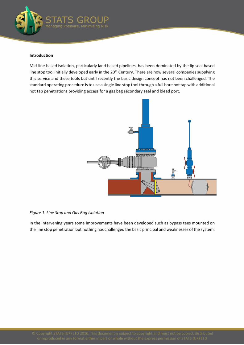
Mid-line based isolation, particularly land based pipelines, has been dominated by the lip seal based line stop tool initially developed early in the 20th Century. There are now several companies supplying this service and these tools but until recently the basic design concept has not been challenged. The standard operating procedure is to use a single line stop tool through a full bore hot tap with additional hot tap penetrations providing access for a gas bag secondary seal and bleed port.
Figure 1: Line Stop and Gas Bag Isolation
In the intervening years some improvements have been developed such as bypass tees mounted on the line stop penetration but nothing has challenged the basic principal and weaknesses of the system.
© Copyright STATS (UK) LTD 2016. This document is subject to copyright and must not be copied, distributed or reproduced in any format either in part or whole without the express permission of STATS (UK) LTD
Piggable Isolation Plugs
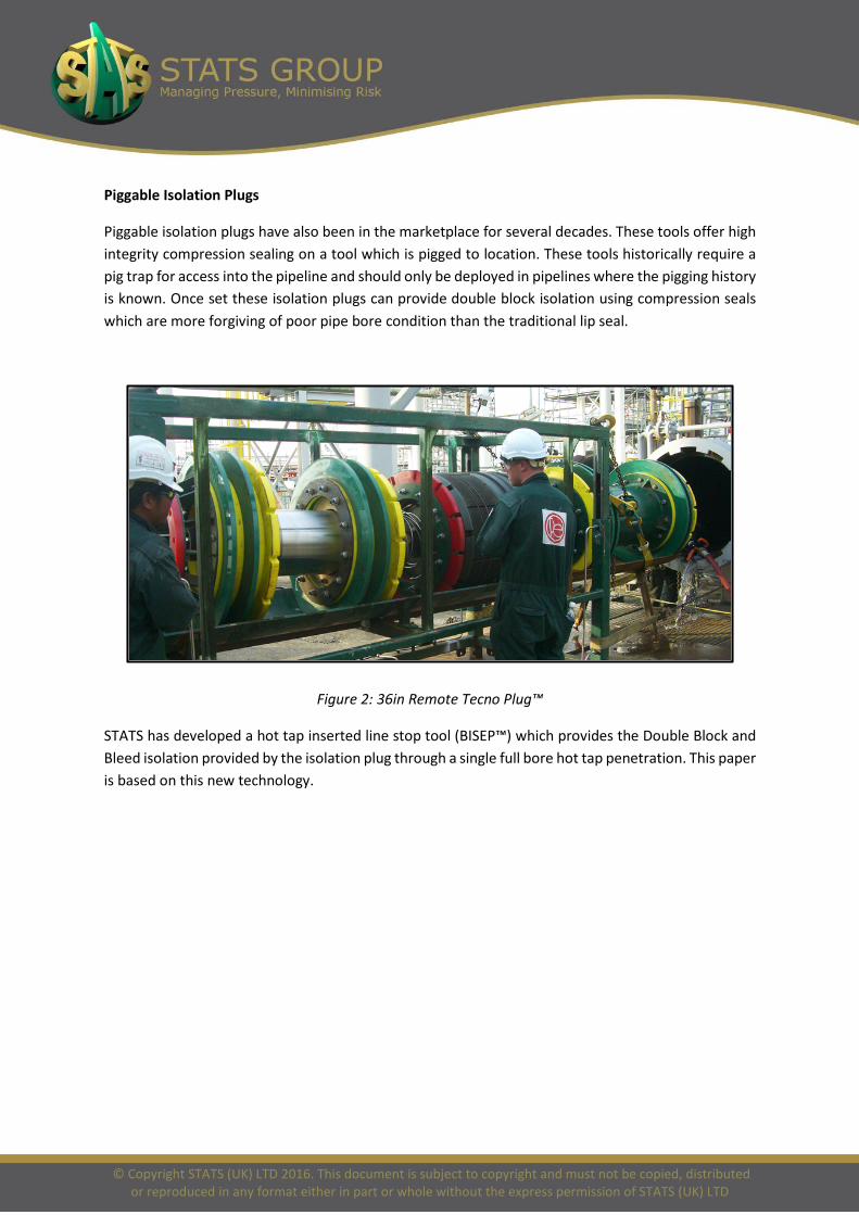
Piggable isolation plugs have also been in the marketplace for several decades. These tools offer high integrity compression sealing on a tool which is pigged to location. These tools historically require a pig trap for access into the pipeline and should only be deployed in pipelines where the pigging history is known. Once set these isolation plugs can provide double block isolation using compression seals which are more forgiving of poor pipe bore condition than the traditional lip seal.
Figure 2: 36in Remote Tecno Plug™
STATS has developed a hot tap inserted line stop tool (BISEP™) which provides the Double Block and Bleed isolation provided by the isolation plug through a single full bore hot tap penetration. This paper is based on this new technology.

© Copyright STATS (UK) LTD 2016. This document is subject to copyright and must not be copied, distributed or reproduced in any format either in part or whole without the express permission of STATS (UK) LTD
BISEP™ Description
The BISEP™ (Branch Installed Self-Energised Plug) comprises a spherical sealing head, clevis arm retention, and pressure competent launcher. The tool is hydraulically operated with fail-safe actuation (self-energisation) via the pipeline pressure differential.
Figure 3: BISEP™
© Copyright STATS (UK) LTD 2016. This document is subject to copyright and must not be copied, distributed or reproduced in any format either in part or whole without the express permission of STATS (UK) LTD
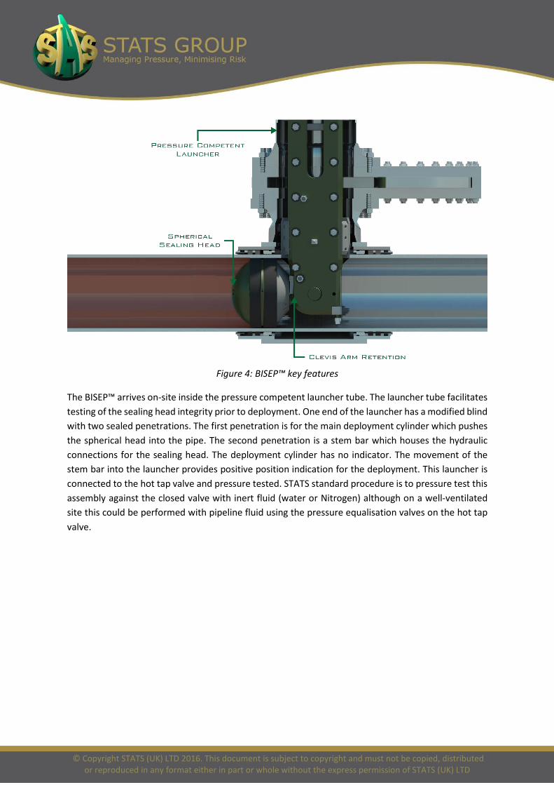
Figure 4: BISEP™ key features
The BISEP™ arrives on-site inside the pressure competent launcher tube. The launcher tube facilitates testing of the sealing head integrity prior to deployment. One end of the launcher has a modified blind with two sealed penetrations. The first penetration is for the main deployment cylinder which pushes the spherical head into the pipe. The second penetration is a stem bar which houses the hydraulic connections for the sealing head. The deployment cylinder has no indicator. The movement of the stem bar into the launcher provides positive position indication for the deployment. This launcher is connected to the hot tap valve and pressure tested. STATS standard procedure is to pressure test this assembly against the closed valve with inert fluid (water or Nitrogen) although on a well-ventilated site this could be performed with pipeline fluid using the pressure equalisation valves on the hot tap valve.

© Copyright STATS (UK) LTD 2016. This document is subject to copyright and must not be copied, distributed or reproduced in any format either in part or whole without the express permission of STATS (UK) LTD
Figure 5: 30in BISEP™ installation
Inside the launcher tube is the sealing head and clevis arm assembly. The deployment cylinder on the launcher drives the spherical head through the hot tap penetration into the pipe where it is rotated 90 degrees, towards the pressure threat, in the opposing direction to the worksite. At this time the sealing head is unset so there is sufficient clearance between the head and the pipe bore to allow pipeline fluid to bypass. As a result this tool can be deployed into a flowing line.
Figure 6: BISEP™ set sequence
The rotation of the sealing head is performed hydraulically to ensure full control. The spherical shape of the head ensures that it can rotate freely inside the pipe while retaining the radial clearance for potential pipeline flow. The pipeline flowrate is limited by the hydraulic force in the rotation cylinder and the current standard design accommodates standard acceptable flowrates for the hot tapping operation. Specials can however be provided for higher flowrates. Head rotation orientates the reaction shoulder against the clevis arms.
Once the head is fully rotated, the seals can be activated. Initial activation is provided by the internally mounted hydraulic cylinder. This axially compresses the two seals, whose resultant radial expansion causes them to compress against the pipe wall, creating a seal. This will provide an isolation of the

© Copyright STATS (UK) LTD 2016. This document is subject to copyright and must not be copied, distributed or reproduced in any format either in part or whole without the express permission of STATS (UK) LTD
pipe and any flow will be stopped. The gradual setting process of the seals ensures a controlled flow termination.
Figure 7: BISEP™ annulus test
The boundary, once established, offers dual leak tight barriers. The annulus between the seals can be pressurised, or depressurised to test the seals. The testing of the dual seals are performed in the isolating direction and so requires the isolated section to be vented to ambient. Thus on a mid-line isolation, both BISEPs™ at either end of the isolation require to be installed and set prior to the isolation being verified. This pressure venting can be performed using the BISEP™ launcher vent ports as the BISEP™ hot tap penetrations are in the isolated zone.
Double Block Verification
Once the isolated section is vented, the BISEP™ has full pressure differential across it. The annulus between the seals will be slightly above the pipeline pressure due to the seal compression reducing the volume of this void. This annulus void is piped through the launcher to give external access which allows the pressure to be raised, if required, to ensure a suitable differential pressure can be locked in for the secondary seal test. Holding the annulus above the pipeline pressure ensures no fluid can pass from the pipeline to the annulus during the secondary seal test.
© Copyright STATS (UK) LTD 2016. This document is subject to copyright and must not be copied, distributed or reproduced in any format either in part or whole without the express permission of STATS (UK) LTD
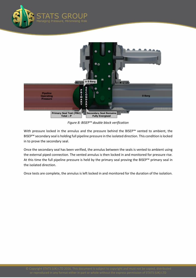
Figure 8: BISEP™ double block verification
With pressure locked in the annulus and the pressure behind the BISEP™ vented to ambient, the BISEP™ secondary seal is holding full pipeline pressure in the isolated direction. This condition is locked in to prove the secondary seal.
Once the secondary seal has been verified, the annulus between the seals is vented to ambient using the external piped connection. The vented annulus is then locked in and monitored for pressure rise. At this time the full pipeline pressure is held by the primary seal proving the BISEP™ primary seal in the isolated direction.
Once tests are complete, the annulus is left locked in and monitored for the duration of the isolation.

© Copyright STATS (UK) LTD 2016. This document is subject to copyright and must not be copied, distributed or reproduced in any format either in part or whole without the express permission of STATS (UK) LTD
Self-Energisation
A vital safety feature of the BISEP™ is self-energisation, where the differential pressure across the BISEP™ head generated by the isolated pipeline pressure retains the seal activation independent of the hydraulics. This self-energisation effect is generated by the relative areas of the whole pipe cross section and the annular seal contact area on the pressure head.
Figure 9: BISEP™ Self-Energisation
The axial movement of the pressure head is retained by the seal and, once fully constrained by the pipe bore, the compression seal generates a contact pressure and can be assessed as a fluid for load calculations.
The pipeline pressure acts on the whole pressure head, generating an axial force towards the seal. An axial load balance across the head shows that the rubber pressure times the radial cross sectional area of the seal contact with the head must equal the load generated by the pipeline pressure. The annular nature of the seal ensures that the seal contact area is significantly less than the disc area of the head so the rubber pressure in the seal is held above that of the pipeline pressure. This has two benefits. Firstly the pipeline pressure can’t pass a seal at higher pressure and secondly this high rubber pressure is highly compliant to pitting, seam welds and poor pipe bore condition. The self-energisation pressure from the pipeline pressure must be sufficient to overcome the initial load to compress the seal out to the pipe wall. This load is defined as the self-energisation pressure, which is the minimum differential pressure across the tool which will maintain the seal in the case of total loss of hydraulic pressure and normally in the region of 10 bar (150 psi).
© Copyright STATS (UK) LTD 2016. This document is subject to copyright and must not be copied, distributed or reproduced in any format either in part or whole without the express permission of STATS (UK) LTD
This axial load then acts on the annulus ring which in turn is retained axially by the secondary seal. Thus the secondary seal is pressurised by the differential across the sealing head in a similar manner to the primary seal. The secondary seal is retained by the seal support head which is a leak tight head equivalent to the pressure head. This seal support head bears on two solid clevis arms, each one capable of taking the full load. The clevis arms are axially retained by the hot tap penetration and fitting.
The assessment above is simplified and does not take account of the hydraulic actuation load which is additional to the differential pressure load. This hydraulic set load is retained and monitored during the isolation to ensure that a loss of pipeline pressure would not result in a loss of either barrier.
Isolation Monitoring
During the period of isolation the following circuits can be monitored:
• Annulus between the seals • Hydraulic set • Hydraulic unset (normally vented) • Body vent – this is the cavity inside the core of the spherical head.
Any change in the status of the isolation would cause a change in these circuits which would provide sufficient warning to either address the change or clear the worksite.
The connection to the annulus does provide the ability to vent any rise in annulus pressure in a similar manner to a double block and bleed valve.
On top of this ability, there is the ability to raise the hydraulic set pressure if required to improve the seal, or reduce the hydraulic pressure to reduce the load on the seal.
Sour Service
The BISEP™ is designed to be compliant with NACE for sour service when fitted with HNBR seals. However during the isolation the clevis arms and associated equipment are in the isolated zone which will be flushed / purged of sour hydrocarbons during the isolation to protect the worksite, therefore the exposure to sour fluid will be minimal. Since the BISEP™ head is deployed outboard of the hot tap penetration, the launchers can be used for access to vent / flush / drain / purge the isolated section. The launchers can also be used to de-air and refill the isolated section after the workscope is complete.

© Copyright STATS (UK) LTD 2016. This document is subject to copyright and must not be copied, distributed or reproduced in any format either in part or whole without the express permission of STATS (UK) LTD
Figure 10: BISEP™ isolating pipeline on-site with dead leg cut away
Pressure Testing
The BISEP™ is designed to resist back pressure so can be used as a test boundary for the reinstatement test. This back pressure is however limited, as the pressure must be retained by the hydraulic set pressure. The BISEP™ is designed to take 50% of the design pressure as a reverse pressure differential. This is a differential pressure and allows a test pressure 50% higher than the isolated pipeline pressure to be applied to the repaired pipe spool as a pressure test prior to removing the BISEP™ isolation.

© Copyright STATS (UK) LTD 2016. This document is subject to copyright and must not be copied, distributed or reproduced in any format either in part or whole without the express permission of STATS (UK) LTD
Failure Modes
The BISEP™ is designed to prevent single failure modes from invalidating the isolation.
For example:
• Failure of pressure head integrity: Annulus ring and seal support head will prevent fluid bypass.
• Failure of primary seal – Secondary seal will maintain isolation: The BISEP™ is designed with sufficient stroke to accommodate the total loss of a single seal.
• Failure of secondary seal – Primary seal will maintain isolation: The BISEP™ is designed with sufficient stroke to accommodate the total loss of a single seal.
• Failure of clevis arm: Second clevis arm capable of retaining full load.
• Failure of hydraulic actuation: Both seals are fully energised by the pipeline pressure.
• Catastrophic loss of pipeline pressure: Both seals are fully energised by the hydraulic pressure.
• Loss of hinge pin: Hinge pin offers no part of the isolation. Pressure test would not however be possible and BISEP™ recovery would be challenging. However this pin is not loaded so failure is remote.
• Breach in annulus hose would allow bypass of secondary seal but the primary seal would be unaffected.
Note: There is no outboard pressure monitor in this tool so there is no single failure exposure from this monitor hose.

© Copyright STATS (UK) LTD 2016. This document is subject to copyright and must not be copied, distributed or reproduced in any format either in part or whole without the express permission of STATS (UK) LTD
BISEP™ Recovery
The BISEP™ is designed to be recoverable in case of control failure. The BISEP™ head will passively unset if the differential pressure is removed and hydraulics are open ended. In this case the annulus and body vent could possibly be pressurised to assist. However if all these lines are allowed to equalise then the head will unset.
If the hydraulics are breached the rotation cylinder will allow the head to be straightened as it is pulled out of the pipe, although some orientations may make this more challenging. Testing has proven that recovery in this condition can be achieved even where the BISEP™ head is deployed vertically beneath the clevis arms.
If the main deployment cylinder failed then it is accessible. Worst case the cylinder could be disconnected from the launcher blind and the BISEP™ recovered mechanically.
Summary
• Hot tap deployed double block and bleed isolation tool.
• Revolutionising market – technology significantly advanced of competition.
• Sealing technology based on Tecno Plug™ sealing – extensive track record.
• Back pressure capability for pressure testing the reinstated pipework.
• Leak-tight sealing.
• Deployed upstream of fitting – vent and purge operations can be performed through launcher.
• Fail-safe: Self-energised sealing.
• Monitor capability during isolation.
Figure 11: BISEP™ load diagram