high gradient accelerating structures for carbon therapy...
TRANSCRIPT
HIGH GRADIENT ACCELERATING STRUCTURES FOR CARBON
THERAPY LINAC*
S.V. Kutsaev1, R. Agustsson1, L. Faillace1, A. Goel2, B. Mustapha2, A. Nassiri2, P. Ostroumov2,
A. Plastun2, and E. Savin1,3
1RadiaBeam Systems, LLC, Santa Monica, CA, 90404, USA 2Argonne National Laboratory, Lemont, IL, 60439, USA
3 National Research Nuclear University «MEPhI», Moscow, Russia
Abstract
Carbon therapy is the most promising among
techniques for cancer treatment, as it has demonstrated
significant improvements in clinical efficiency and
reduced toxicity profiles in multiple types of cancer
through much better localization of dose to the tumor
volume. RadiaBeam Systems, in collaboration with
Argonne National Laboratory, are developing a high-
gradient linear accelerator, Advanced Compact Carbon
Ion Linac (ACCIL), for the delivery of ion beams with
end-energies up to 450 MeV/u for 12C6+ ions and 250
MeV for protons. In this paper, we present a thorough
comparison of standing and traveling wave designs for
high gradient S-Band accelerating structures operating
with ions at various velocities, relative to the speed of
light, in the range 0.3-0.7. In this paper, we will compare
these types of accelerating structures regarding RF, beam
dynamics, and thermo-mechanical performance.
INTRODUCTION
ACCIL is designed for the full energy range from the
ion source to 450 MeV/u for 12C6+ and includes the
following main sections: a radio-frequency quadrupole
(RFQ) accelerator, a drift-tube linac (DTL), and a
coupled-DTL sections operating at a sub-harmonic of the
S-band frequency to accelerate carbon ions up to 45
MeV/m. For effective acceleration to higher energies, a
high gradient S-band structure will be used. An overview
of the linac is given in [1].
The compact footprint of ACCIL (8x45m) can be
achieved if the accelerating structure capable of providing
50 MV/m for the particles with beta from 0.3 to 0.7 is
developed. Such high accelerating gradients of the
ACCIL linac will be feasible due to the operation at high
frequency, 2856 MHz, at very low duty cycle <0.06% and
very short <0.5 μs beam pulses. The known RF
breakdown limit is much higher for high-frequency
structures than for traditional low-β structures operating at lower frequencies.
There are several known criteria for RF breakdown
limit that we have used for the EM design: Peak surface fields of 250 MV/m at 11-12 GHz,
and ~160 MV/m for S-band have been
demonstrated in RF guns and side-coupled linacs
[2,3,4];
Peak surface magnetic field that causes pulse
heating, which can damage the structure if the
peak temperature rise is higher than 50 oC [5]; There are also new theories of a unified criterion,
such as a modified Poynting vector (<S>) [6]
that may impact the gradients. However, there is
not many experimental data for S-band
structures;
In our design, we considered keeping all three
parameters below known limits.
HIGH BETA STRUCTURE
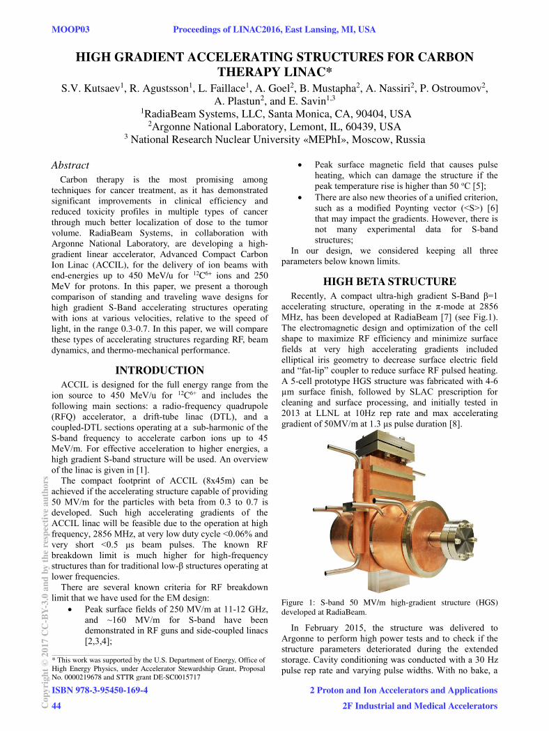
Recently, A compact ultra-high gradient S-Band β=1
accelerating structure, operating in the π-mode at 2856
MHz, has been developed at RadiaBeam [7] (see Fig.1).
The electromagnetic design and optimization of the cell
shape to maximize RF efficiency and minimize surface
fields at very high accelerating gradients included
elliptical iris geometry to decrease surface electric field
and “fat-lip” coupler to reduce surface RF pulsed heating.
A 5-cell prototype HGS structure was fabricated with 4-6
µm surface finish, followed by SLAC prescription for
cleaning and surface processing, and initially tested in
2013 at LLNL at 10Hz rep rate and max accelerating
gradient of 50MV/m at 1.3 μs pulse duration [8].
Figure 1: S-band 50 MV/m high-gradient structure (HGS)
developed at RadiaBeam.
In February 2015, the structure was delivered to
Argonne to perform high power tests and to check if the
structure parameters deteriorated during the extended
storage. Cavity conditioning was conducted with a 30 Hz
pulse rep rate and varying pulse widths. With no bake, a
____________________________________________
* This work was supported by the U.S. Department of Energy, Office of
High Energy Physics, under Accelerator Stewardship Grant, Proposal
No. 0000219678 and STTR grant DE-SC0015717
MOOP03 Proceedings of LINAC2016, East Lansing, MI, USA
ISBN 978-3-95450-169-444Co
pyrig
ht©
2017
CC-B
Y-3.
0an
dby
ther
espe
ctiv
eaut
hors
2 Proton and Ion Accelerators and Applications2F Industrial and Medical Accelerators
max field level of ~40 MV/m was achieved at 10 MW
power and 2 μs pulse length. However, severe outgassing
prevented further progress. After three days bake, the
static vacuum levels improved by one order of magnitude.
Following this, a stable field of ~44 MV/m was achieved
but again outgassing issues prevented progress. After
another bake and about two weeks of RF conditioning
peak field levels of 52 MV/m were obtained at 16.7 MW
power and 2 μs pulse length and sustained for 24 hours.
Further attempts to increase the peak fields in the cavity
by increasing pulse width resulted in an internal failure of
the cavity.
To determine the cause of the failure, the cavity surface
was observed by a borescope. Multiple imperfections
were observed ranging from pitting marks in the iris areas
to arcing in the central waveguide feed area, possibly, due
to pulse heating effect. No baseline observations with a
borescope were made before the start of the test, so it is
hard to determine how much of the observed damage was
pre-existing and how much was induced by the testing at
APS. However, from the amount of time and difficulty of
reaching high gradients during the tests at APS, it appears
that the cavity had some residual damage from previous
testing efforts. From start to finish the test ran for about
seven weeks.
MAGNETIC COUPLED STRUCTURE
The same approach of cavity design, however, can’t be applied to the low-energy section. Although coupled
cavity linac (CCL) types of accelerating structures
demonstrate excellent performance when designed for
particles with high β, its RF parameters degrade dramatically for structures with β<0.7.
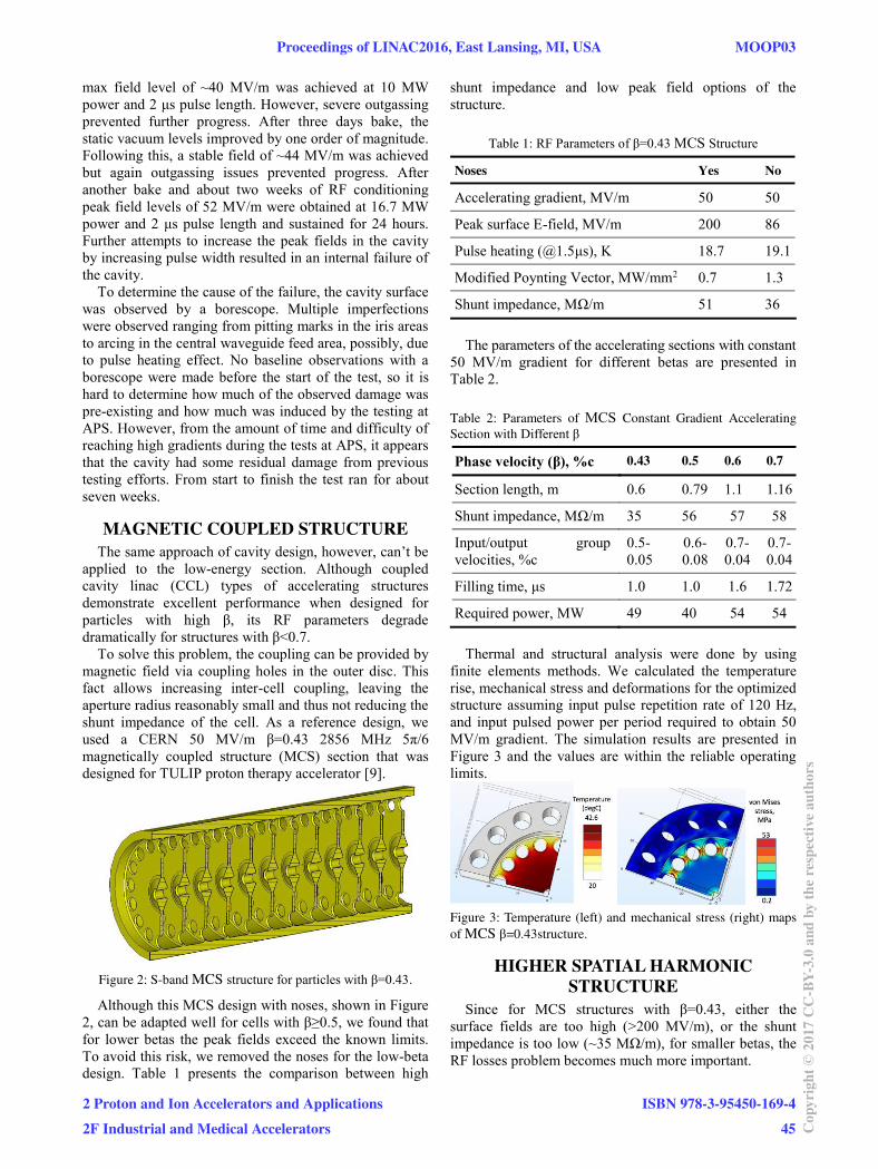
To solve this problem, the coupling can be provided by
magnetic field via coupling holes in the outer disc. This
fact allows increasing inter-cell coupling, leaving the
aperture radius reasonably small and thus not reducing the
shunt impedance of the cell. As a reference design, we
used a CERN 50 MV/m β=0.43 2856 MHz 5π/6 magnetically coupled structure (MCS) section that was
designed for TULIP proton therapy accelerator [9].
Figure 2: S-band MCS structure for particles with β=0.43.
Although this MCS design with noses, shown in Figure
2, can be adapted well for cells with β≥0.5, we found that
for lower betas the peak fields exceed the known limits.
To avoid this risk, we removed the noses for the low-beta
design. Table 1 presents the comparison between high
shunt impedance and low peak field options of the
structure.
Table 1: RF Parameters of β=0.43 MCS Structure
Noses Yes No
Accelerating gradient, MV/m 50 50
Peak surface E-field, MV/m 200 86
Pulse heating (@1.5μs), K 18.7 19.1
Modified Poynting Vector, MW/mm2 0.7 1.3
Shunt impedance, MΩ/m 51 36
The parameters of the accelerating sections with constant 50 MV/m gradient for different betas are presented in
Table 2.
Table 2: Parameters of MCS Constant Gradient Accelerating
Section with Different β
Phase velocity (β), %c 0.43 0.5 0.6 0.7
Section length, m 0.6 0.79 1.1 1.16
Shunt impedance, MΩ/m 35 56 57 58
Input/output group
velocities, %c
0.5-
0.05
0.6-
0.08
0.7-
0.04
0.7-
0.04
Filling time, μs 1.0 1.0 1.6 1.72
Required power, MW 49 40 54 54
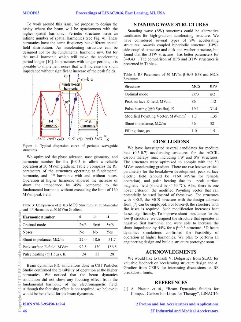
Thermal and structural analysis were done by using
finite elements methods. We calculated the temperature
rise, mechanical stress and deformations for the optimized
structure assuming input pulse repetition rate of 120 Hz,
and input pulsed power per period required to obtain 50
MV/m gradient. The simulation results are presented in
Figure 3 and the values are within the reliable operating
limits.
Figure 3: Temperature (left) and mechanical stress (right) maps
of MCS β=0.43structure.
HIGHER SPATIAL HARMONIC
STRUCTURE
Since for MCS structures with β=0.43, either the
surface fields are too high (>200 MV/m), or the shunt
impedance is too low (~35 MΩ/m), for smaller betas, the
RF losses problem becomes much more important.
Proceedings of LINAC2016, East Lansing, MI, USA MOOP03
2 Proton and Ion Accelerators and Applications2F Industrial and Medical Accelerators
ISBN 978-3-95450-169-445 Co
pyrig
ht©
2017
CC-B
Y-3.
0an
dby
ther
espe
ctiv
eaut
hors
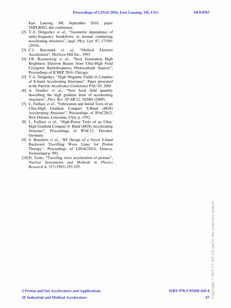
To work around this issue, we propose to design the
cavity where the beam will be synchronous with the
higher spatial harmonic. Periodic structures have an
infinite number of spatial harmonics (see Fig. 4). These
harmonics have the same frequency but different spatial
field distribution. An accelerating structure can be
designed not for the fundamental harmonic m=0 but for
the m=-1 harmonic which will make the accelerating
period longer [10]. In structures with longer periods, it is
possible to implement noses that will increase the shunt
impedance without significant increase of the peak fields.
Figure 4: Typical dispersion curve of periodic waveguide
structures.
We optimized the phase advance, nose geometry, and
harmonic number for the β=0.3 to allow a reliable
operation at 50 MV/m gradient. Table 3 compares the RF
parameters of the structures operating at fundamental
harmonic, and -1st harmonic with and without noses.
Operation at higher harmonic allowed the increase of
shunt the impedance by 45% compared to the
fundamental harmonic without exceeding the limit of 160
MV/m peak field.
Table 3: Comparison of β=0.3 MCS Structures at Fundamental
and -1st Harmonic at 50 MV/m Gradient
Harmonic number 0 -1 -1
Optimal mode 2π/3 5π/6 5π/6
Noses No No Yes
Shunt impedance, MΩ/m 22.0 18.6 31.7
Peak surface E-field, MV/m 92.5 130 156.5
Pulse heating (@1.5μs), K 24 33 28
Beam dynamics PIC simulations done in CST Particles
Studio confirmed the feasibility of operation at the higher
harmonics. We noticed that the beam dynamics
simulation did not show any focusing effect from the
fundamental harmonic of the electromagnetic field.
Although the focusing effect is not required, we believe it
would be beneficial for the beam dynamics.
STANDING WAVE STRUCTURES
Standing wave (SW) structures could be alternative
candidates for high-gradient accelerating structure. We
have considered several types of SW accelerating
structures: on-axis coupled biperiodic structure (BPS),
side-coupled structure and disk-and-washer structure, but
found that the BTW structure has better parameters for
β=0.43 . The comparison of BPS and BTW structures is
presented in Table 4.
Table 4: RF Parameters of 50 MV/m β=0.43 BPS and MCS Structures
Structure MCS BPS
Optimal mode 2π/3 π/2
Peak surface E-field, MV/m 86 112
Pulse heating (@0.5μs flat), K 19.1 31.4
Modified Poynting Vector, MW/mm2 1.3 1.35
Shunt impedance, MΩ/m 36 32
Filling time, μs 1.0 1.5
CONCLUSIONS
We have investigated several candidates for medium
beta (0.3-0.7) accelerating structures for the ACCIL
carbon therapy linac including TW and SW structures.
The structures were optimized to comply with the 50
MV/m accelerating gradient. There are two known critical
parameters for the breakdown development: peak surface
electric field (should be <160 MV/m for reliable
operation), and pulse heating due to peak surface
magnetic field (should be < 50 oC). Also, there is one
novel criterion, the modified Poynting vector that can
potentially be used instead of these two. For structures
with β≥0.5, the MCS structure with the design adopted
from [7] can be employed. For lower-β, the structure with
flat irises is required. Such modification increases heat
losses significantly. To improve shunt impedance for the
low-β structure, we designed the structure that operates at
negative first harmonic and were able to increase the
shunt impedance by 44% for a β=0.3 structure. 3D beam
dynamics simulations confirmed the feasibility of
operation at higher harmonics. We plan to perform an
engineering design and build a structure prototype soon.
AСKNOWLEGMENTS
We would like to thank V. Dolgashev from SLAC for
valuable feedback on accelerating structure design and A.
Grudiev from CERN for interesting discussions on RF
breakdown limits.
REFERENCES
[1] A. Plastun et al., “Beam Dynamics Studies for
Compact Carbon Ion Linac for Therapy”, LINAC16,
MOOP03 Proceedings of LINAC2016, East Lansing, MI, USA
ISBN 978-3-95450-169-446Co
pyrig
ht©
2017
CC-B
Y-3.
0an
dby
ther
espe
ctiv
eaut
hors
2 Proton and Ion Accelerators and Applications2F Industrial and Medical Accelerators
East Lansing, MI, September 2016, paper
THPLR042, this conference.
[2] V.A. Dolgashev et al., “Geometric dependence of radio-frequency breakdown in normal conducting
accelerating structures”, Appl. Phys. Lett. 97, 171501
(2010).
[3] C.J. Karzmark et. al, “Medical Electron Accelerators”, McGraw-Hill Inc., 1993.
[4] J.B. Rosenzweig et al., “Next Generation High
Brightness Electron Beams from Ultra-High Field
Cryogenic Radiofrequency Photocathode Sources”,
Proceedings of ICHEP 2016, Chicago.
[5] V.A. Dolgashev, “High Magnetic Fields in Couplers of X-band Accelerating Structures”. Paper presented
at the Particle Accelerator Conference PAC 03, 2003
[6] A. Grudiev et al., “New local field quantity describing the high gradient limit of accelerating
structures”, Phys. Rev. ST-AB 12, 102001 (2009).
[7] L. Faillace et al., “Fabrication and Initial Tests of an Ultra-High Gradient Compact S-Band (HGS)
Accelerating Structure”, Proceedings of IPAC2012,
New Orleans, Louisiana, USA, p. 3392.
[8] L. Faillace et al., “High-Power Tests of an Ultra-
High Gradient Compact S- Band (HGS) Accelerating
Structure”, Proceedings of IPAC13, Dresden,
Germany.
[9] S. Benedetti et al., “RF Design of a Novel S-band
Backward Travelling Wave Linac for Proton
Therapy”, Proceedings of LINAC2014, Geneva,
Switzerland p. 992.
[10] D. Tronc, “Traveling wave acceleration of protons”, Nuclear Instruments and Methods in Physics
Research A, 327 (1993) 253-255.
Proceedings of LINAC2016, East Lansing, MI, USA MOOP03
2 Proton and Ion Accelerators and Applications2F Industrial and Medical Accelerators
ISBN 978-3-95450-169-447 Co
pyrig
ht©
2017
CC-B
Y-3.
0an
dby
ther
espe
ctiv
eaut
hors