high extinction ratio widely tunable low-loss...
TRANSCRIPT

High Extinction Ratio Widely Tunable Low-Loss Integrated Si3N4 Third-Order Filter
TARAN HUFFMAN1, DOUG BANEY2, DANIEL J. BLUMENTHAL*1 1Department of Electrical and Computer Engineering, University of California, Santa Barbara, CA
93106, USA 2Keysight Laboratories, Keysight Technologies, 5301 Stevens Creek Blvd., Santa Clara, CA 95051, USA
Abstract: We demonstrate an integrated continuously tunable third-order ring filter
with a measured extinction ratio of 80dB, a 100x improvement over previously
demonstrated integrated 3rd or 6th order filters. Using integrated thermal tuning
elements, the filter can be tuned over 100% of its 48 GHz free spectral range with 1.3
dB insertion loss. The filters are fabricated on a wafer-scale foundry compatible Si3N4
low-loss platform enabling integration with a wide variety of previously demonstrated
passive and active elements. The high extinction ratio, low loss, flat passband and steep
roll-off is desirable for a broad range of applications including pump-stokes separation
for Brillouin scattering, idler separation in four-wave mixing and separation of
entangled states for quantum communications that utilize nonlinear optics.
OCIS codes: (300.0300) Spectroscopy; (230.7390) Waveguides, planar; (230.5750) Resonators
References
1. Kittlaus, Eric A., Heedeuk Shin, and Peter T. Rakich. "Large Brillouin amplification in silicon." Nature Photonics (2016).
2. Hua, Shiyue, Jianming Wen, Xiaoshun Jiang, Qian Hua, Liang Jiang, and Min Xiao, “Demonstration of a chip-
based optical isolator with parametric amplification,” Nature Communications | 7:13657 | DOI: 10.1038/Ncomms13657
3. Silverstone, Joshua W., Bonneau D, Ohira K, Suzuki N, Yoshida H, Iizuka N, Ezaki M, Natarajan CM, Tanner
MG, Hadfield RH, Zwiller V. "On-chip quantum interference between silicon photon-pair sources." Nature Photonics 8.2 (2014): 104-108.
4. Popovíc, Miloš A., Tymon Barwicz, Michael R. Watts, Peter T. Rakich, Luciano Socci, Erich P. Ippen, Franz
X. Kärtner, and Henry I. Smith. "Multistage high-order microring-resonator add-drop filters." Optics Letters
31.17 (2006): 2571-2573.
5. Smith, Henry, Tymon Barwicz, Charles W. Holzwarth, Milos A. Popovic, Michael R. Watts, Peter T. Rakich,
Minghao Qi, Raul Barreto, Franz X. Kärtner, and Erich P. Ippen. "Strategies for fabricating strong-confinement microring filters and circuits." Optical Fiber Communication Conference. Optical Society of America, 2007.
6. Little, Brent. "Advances in microring resonators." Integrated Photonics Research. Optical Society of America,
2003. 7. Little, B. E., Chu, S.T., Absil, P.P., Hryniewicz, J.V., Johnson, F.G., Seiferth, F., Gill, D., Van, V., King, O. and
Trakalo, M. "Very high-order microring resonator filters for WDM applications." IEEE Photonics Technology
Letters 16.10 (2004): 2263-2265. 8. Little, Brent, Chu, S., Chen, W., Hryniewicz, J., Gill, D., King, O., Johnson, F., Davidson, R., Donovan, K.,
Chen, W. and Grubb, S. "Tunable bandwidth microring resonator filters." Optical Communication, 2008. ECOC
2008. 34th European Conference on. IEEE, 2008. 9. Dong, Po, Feng, N.N., Feng, D., Qian, W., Liang, H., Lee, D.C., Luff, B.J., Banwell, T., Agarwal, A., Toliver,
P. and Menendez, R. "GHz-bandwidth optical filters based on high-order silicon ring resonators." Optics
Express 18.23 (2010): 23784-23789. 10. Orlandi, P., Morichetti, F., Strain, M. J., Sorel, M., Bassi, P., & Melloni, A. "Photonic integrated filter with
widely tunable bandwidth." Journal of Lightwave Technology 32, no. 5 (2014): 897-907.
11. Ong, Jun Rong, Ranjeet Kumar, and Shayan Mookherjea. "Ultra-high-contrast and tunable-bandwidth filter using cascaded high-order silicon microring filters." IEEE Photonics Technology Letters 25.16 (2013): 1543-
1546.
12. Jared F Bauters, Martijn JR Heck, Demis John, Daoxin Dai, Ming-Chun Tien, Jonathon S. Barton, Arne Leinse, René G. Heideman, Daniel J. Blumenthal, and John E. Bowers. "Ultra-low-loss high-aspect-ratio Si 3 N 4
waveguides." Optics express 19, no. 4 (2011): 3163-3174.
13. A. Leinse, Shaoxian Zhang and R. Heideman, "TriPleX: The versatile silicon nitride waveguide platform," 2016 Progress in Electromagnetic Research Symposium (PIERS), Shanghai, 2016, pp. 67-67.
14. Chaichuay, Chinda, Preecha P. Yupapin, and Prajak Saeung. "The serially coupled multiple ring resonator
filters and Vernier effect." Opt. Appl 39.1 (2009): 175-194. 15. Belt, Michael, and Daniel J. Blumenthal. "Erbium-doped waveguide DBR and DFB laser arrays integrated
within an ultra-low-loss Si 3 N 4 platform." Optics Express 22.9 (2014): 10655-10660.
16. Piels, M., Bauters, J. F., Davenport, M. L., Heck, M. J., & Bowers, J. E. (2014). Low-loss silicon nitride AWG demultiplexer heterogeneously integrated with hybrid III–V/silicon photodetectors. Journal of Lightwave
Technology, 32(4), 817-823.
17. Moreira, Renan L., John Garcia, Wenzao Li, Jared Bauters, Jonathon S. Barton, Martijn JR Heck, John E. Bowers, and Daniel J. Blumenthal. "Integrated ultra-low-loss 4-bit tunable delay for broadband phased array
antenna applications." IEEE Photon. Technol. Lett 25.12 (2013): 1165-1168.
18. Rabus, Dominik G. Integrated ring resonators. Springer-Verlag Berlin Heidelberg, 2007. 19. Huffman, T., Davenport, M., Belt, M., Bowers, J. E., & Blumenthal, D. J. (2016). Ultra-low loss large area
waveguide coils for integrated optical gyroscopes. IEEE Photonics Technology Letters, 29(2), 185-188.
20. Sudbo, A. Sv. "Film mode matching: a versatile numerical method for vector mode field calculations in dielectric waveguides." Pure and Applied Optics: Journal of the European Optical Society Part A 2.3 (1993):
211.
21. Amatya, Reja, Charles W. Holzwarth, M. A. Popovic, F. Gan, H. I. Smith, F. Kartner, and R. J. Ram. "Low
power thermal tuning of second-order microring resonators." Conference on Lasers and Electro-Optics. Optical
Society of America, 2007.
22. Mak, J. C., Sacher, W. D., Xue, T., Mikkelsen, J. C., Yong, Z., & Poon, J. K. (2015). Automatic resonance alignment of high-order microring filters. IEEE Journal of Quantum Electronics, 51(11), 1-11.
1 Introduction Widely tunable filters with very high extinction ratios, low loss, and flat passbands are
important for many applications including communications, lasers, spectroscopy and nonlinear
optics. Examples include separating pump and Stokes signals for Brillouin scattering [1],
filtering of idler signals in FWM processes for nonlinear micro-resonators and non-magnetic
optical isolation [2], and quantum communications and computing that employ frequency
conversion [3].
Integrated planar waveguide coupled-ring structures have been shown to realize filters with
reduced cost and fabrication complexity and scaling to larger more complex PIC circuits. To
date multiple-order non-tunable ring filters have been demonstrated with extinction ratios of up
to 70dB. Popovíc, Miloš A., et al. [4] and Smith, Henry, et al. [5] demonstrated high
confinement silicon rich SixN4 third-order ring filters with 50dB and 60dB extinction ratios,
respectively, and FSRs up to 2500GHz. Little, et al. demonstrated 3rd order filters with 50dB
extinction ratio with 3dB bandwidth between 10-15GHz and 6th order filters with extinction
ratio on the order of 60dB [6,7], with a discretely tunable passband shape [8]. In addition, Little
presented results on an 11th order filter with asymmetric shape that experimentally demonstrated
50 dB symmetric extinction ratio and approximately 70dB asymmetric extinction ratio without
clear measurement of the filter stopband [7] and discrete tuning over an unspecified percentage
of the FSR. Dong, Po, et al. demonstrated silicon 5th order tunable ring filters with up to 50dB
extinction and an FSR of 50GHz [9]. P. Orlandi et al. utilized a ring-loaded MZI geometry to
demonstrate 10dB – 45dB ER with tuning ranges up to 90% of 200GHz FSR with a 20dB
extinction ratio [10]. Jung Rong Ong reported a 60dB ER 5th order filter using silicon
microrings, that demonstrated a shapeable passband and was tunable over a small portion of its
FSR [11].
In this work, we report the demonstration of a widely tunable third-order ring filter with
80dB extinction ratio, a 100x improvement in extinction ratio over prior art 3rd and 6th order
filters [6] and 3000x larger tuning range than reported in [10]. The filter is continuously tunable
over 100% of the free spectral range using the thermo-optic effect with a measured insertion
loss of 1.3dB. The filters are fabricated using the Si3N4 ultra-low loss waveguide platform
(ULLW) reported in [12] and are compatible with the wafer-scale foundry processes described
in [13]. This advance in state of the art is due to the low waveguide propagation losses and
reproducible and accurate waveguide coupling regions as well as the ability to design and
implements large FSR tunable structures. Tuning is achieved with monolithically integrated
waveguide heaters for each ring. We use a unit-less quantity called the filter shape factor (SF)

defined as the ratio of the -1dB and -10dB bandwidths [14] to evaluate the filter passband roll
off. We report a measured shape factor better than 0.4 that is maintained while tuning over the
full 48.2GHz FSR. Implementation of this filter in the Si3N4 platform lends to monolithic
integration with a wide range of both active and passive components that have been previously
demonstrated, including Si3N4-core waveguides with co-doped AL2O3:Er3+ doped narrow
linewidth WDM sources [15], AWGRs [16] and thermal switches and delay lines [17].
2 Integration Platform The filter consists of three coupled-ring waveguide resonators interfaced via directional
couplers to input and output bus waveguides as illustrated in Fig. 1 (a). S-bends to the
directional couplers are used to isolate the fiber-coupled input and output buses from the ring
resonators. The low loss waveguides, couplers, and rings are fabricated in a common planar
wafer-scale compatible structure illustrated in Fig. 1 (b) that incorporates a thin Si3N4 core, a
thermally grown SiO2 on silicon lower cladding and a PECVD deposited upper cladding layer
with a metal heater layer deposited on top to thermally tune the rings.
The waveguide propagation loss components are defined by sidewall scattering at the core-
cladding interface, the waveguide bend radius, and the material losses at the operational
wavelengths. The sidewall scattering loss scales quadratically with the interface roughness and
dominates the waveguide losses for bends larger than the critical loss radius. We employ high-
aspect ratio waveguides (t1<<w) to reduce the scattering loss of the etched waveguide sidewalls
[12]. This large aspect ratio causes the TE mode to be more highly confined than the TM mode
allowing the TE mode to propagate in smaller radius bends than the TM mode before
experiencing significant bend loss.
Fig. 1. (a) Third-order ring filter design; (b) Schematic cross section of Si3N4 low loss waveguide. In this device, we use nitride
core thickness t1 = 175nm, core width w = 2.2µm and upper cladding thickness t2 =6.8µm. Thermal oxide lower cladding
thickness is 15 microns.
3 Third-Order Filter Design
The basic filter design and parameters are shown in Fig. 2. The coupling between rings and the
bus waveguides, the ring radius, and the waveguide loss determine the performance and shape
of the filter including extinction ratio, shape factor, and ripple.

Fig. 2. Bus coupled ring-resonator third-order filter design and parameters.
The transfer function of the drop port Tdrop, designated as the ratio of the output optical
power to the input optical power, is defined using Mason’s rule [14] and given in Eq. (1). Light
passing through couplers without coupling is represented by the parameter Ci, while light
coupling between waveguides is represented by the parameter Si, and the attenuation and phase
of light traveling around a ring is represented by the parameter ξ. These parameters are defined
in Eqns. (2-4) and are illustrated in Fig. 2. Here L is the round-trip length of the ring, α is the
propagation loss of the waveguide, and β the waveguide propagation constant.
𝑇𝑑𝑟𝑜𝑝 =𝑆1𝑆2𝑆3𝑆4𝜉
32⁄
1−𝐶1𝐶2𝜉+𝐶1𝐶3𝜉2+𝐶2𝐶4𝜉2−𝐶1𝐶4𝜉3+𝐶1𝐶2𝐶3𝐶4𝜉2 (1)
𝐶𝑖 = ((1 − 𝜅𝑖)(1 − 𝛾))12⁄ (2)
−𝑗𝑆𝑖 = −((1 − 𝑗𝛾)𝜅𝑖)12⁄ (3)
𝜉 = 𝑒𝛼𝐿
2⁄ 𝑒−𝑗𝛽𝐿 (4)
The shape factor is defined as the ratio of bandwidth at the -1dB and -10dB points where a
shape factor of 1 is a perfect box-like filter function. For a given radius and propagation loss,
the ratio of κ1 and κ2 determine the ripple, insertion loss (IL) and extinction ratio (ER). To
minimize the filter IL, the bus to ring coupling constants are set to κ1 = κ4 and ring to ring
coupling constants κ2= κ3 as described in [18]. High ratio values of κ2 to κ1 will produce low
ER and high ripple whereas low values will decrease the shape factor and increase insertion
loss. A maximally flat filter shape is derived for the lossless case given in [18] as κ12 = .125 ∗
κ24. Changing 1 and 2 from this ideal case allows the ER and IL of the filter to be varied.
Fig. 3 (a) shows the calculated drop port transfer function with an ideal coupling ratio, Fig.
3 (b) shows the drop port transfer function with a low coupling ratio, and Fig. 3 (c) shows the
drop port transfer function with a high coupling ratio. In these plots and all plots throughout
this paper, the frequency dependent filter transmission is relative to a 1550nm center
wavelength.

Fig. 3. Calculated drop port transfer function, (a) Shows an ideal coupling ratio filter with κ2=0.006, yielding SF=0.6, ER=77dB,
and IL=1.4dB, (b) Shows an under coupled filter with κ2=0.001, yielding SF=.26, ER=90, and IL=3.6, (c) Shows an over
coupled filter with κ2=0.01, yielding SF=0.82, ER=67dB, IL=1dB, and ripple =2dB. All filters have a radius of 580µm, κ1
of 0.15, and loss of 20dB/m.
4 Filter Design
4.1 Waveguide Geometry
An important design space is the tradeoff between filter performance and filter area. These
factors are set by the waveguide propagation loss and minimum bend radius as determined by
the Si3N4 core thickness and waveguide width. Thicker cores have higher sidewall scattering
loss but a lower critical bend radius while thinner cores can greatly reduce the scattering
propagation loss but result in a larger critical bend radius. The critical bend radius is defined as
where the bend loss contribution is equal to 0.1dB/m. Table 1 summarizes experimental and
simulated propagation loss values and bend limits for different core thicknesses as reported in
[19,12]. In this work, the filter was designed for a 50GHz FSR and based on the parameters
in Table 1, a core thickness of 175nm was selected. Waveguide mode intensity profiles for both
the TE and TM modes in a 175nm thick core design were simulated using FIMMWAVE and
the film mode matching technique [20] and are shown in Fig. 4. For this design, we chose TM
operation due to initial fabrication runs that resulted in high interface roughness between the
core and upper cladding from our sputtered upper cladding deposition process. The higher than
expected interfaced roughness resulted in unacceptable TE losses. Using a PECVD deposition
process for the upper cladding deposition reduced the TE mode loss, and this is reported for the
results in section 6. Designing the filter for the TE mode using low loss deposition would allow
reduction of the bend radius and therefore an increase in the FSR and decrease the round-trip
loss.
Table 1. Filter FSR and waveguide loss and critical bend radius dependence on core thickness
Core Thickness (nm) Scattering Loss (dB/m) Bend Limit (mm) FSR Limit (GHz)
40 0.2 — 0.5 (TE) 11 2.93
60 0.8 — 3 (TE) 3 10.7
90 1 — 6 (TE) 1 32.3
175 (this work) 10 — 20 (TE & TM) .5 (TM) 63.6

Fig. 4. Simulated mode shapes for both the (a) TE and (b) TM mode for a 175nm thick and 2.2um wide Si3N4 core.
4.2 Coupler Design
The coupling coefficients for the bus to ring and ring to ring couplers, κ1 and κ2, have a
significant impact on filter performance. Simulating directional couplers with the precision
needed to engineer a high extinction ratio third-order filter design requires calibration with the
fabrication process. To determine the precise relationship between the waveguide coupling gaps
and coupling coefficients, a coupling parameter split test run was fabricated and measured. We
then used measured results of the fabricated first-order filter to design the third-order filter.
A first-order ring filter test structure, shown in Fig. 5, was used to calibrate the coupling
coefficients to the coupling waveguide gap. The drop-port characteristics were measured with
a laser wavelength sweep into a photodetector. The resulting filter shape was then fit to the
equation for the drop port characteristic of a first-order ring in [14] using a least-squares fit, as
shown in Fig. 6 (a). This yields the relationship between coupling gap and coupling coefficient,
shown in Fig. 6 (b) for the TM mode.
Fig. 5. Thermally tuned single order ring filter test structure with R=625μm.
The ratio between κ1 and κ2 was chosen for a target ER of 80 dB and a flat passband. The
physical gap values used on the mask, and the corresponding intended coupling coefficients
from Fig. 6 (b), for the third-order rings are summarized in Table 2.

Fig. 6. (a) The analytic fit to a first order ring filter and (b) the measured trend across multiple radii and gaps for the TM mode.
Table 2. Gap values with corresponding Predicted Kappa Values
Gap (µm) Kappa
Bus Coupler 1.15 .13
Ring to Ring Coupler 2.4 .06
4.3 Heater Layer and Upper Cladding Thickness
Si3N4 waveguides can be thermally tuned [21] using a resistive metal layer on the upper
cladding over the core. The heaters are an absorptive metal layer deposited directly over the
waveguide requiring careful selection of the upper cladding thickness, balancing excess loss
from optical mode overlap with the heater and heater power tuning efficiency. Fig. 7 shows
FIMMWAVE simulations of the estimated optical loss as a function of the upper cladding
thickness. Modes with upper claddings thicker than 6.5µm will experience negligible loss from
the metal layer.
Fig. 7. Metal absorption loss as a function of upper cladding thickness for the TM mode.
5 Fabrication Process
Fabrication begins with a 1mm thick Si substrate wafer with 15µm of thermally grown SiO2.
The 175nm core is deposited using low-pressure chemical vapor deposition (LPCVD)
performed by Rogue Valley Microdevices. The core is defined using DUV lithography and a
dry etch consisting of CHF3, CF4, and O2. The upper cladding is deposited using plasma-
enhanced chemical vapor deposition (PECVD). The deposition is performed in 3.4µm steps
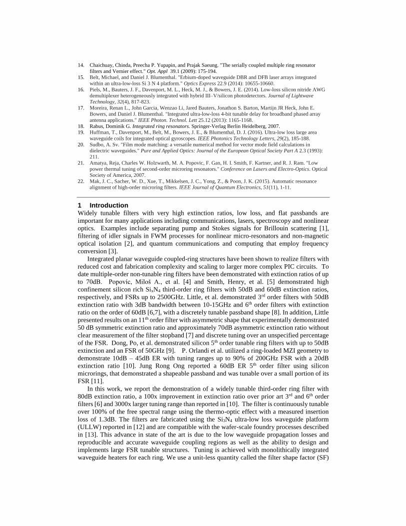
and annealed for 7 hours at 1050º C after each deposition. The process flow is shown in Fig. 8
processing quantities summarized in Table 2 Further details on the fabrication process can be
found in [12].
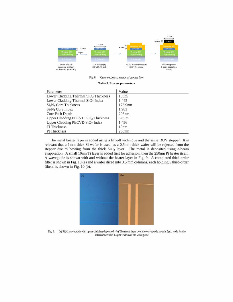
Fig. 8. Cross-section schematic of process flow.
Table 3. Process parameters
Parameter Value
Lower Cladding Thermal SiO2 Thickness 15µm
Lower Cladding Thermal SiO2 Index 1.445
Si3N4 Core Thickness 173.9nm
Si3N4 Core Index 1.983
Core Etch Depth 206nm
Upper Cladding PECVD SiO2 Thickness 6.8µm
Upper Cladding PECVD SiO2 Index 1.456
Ti Thickness 10nm
Pt Thickness 250nm
The metal heater layer is added using a lift-off technique and the same DUV stepper. It is
relevant that a 1mm thick Si wafer is used, as a 0.5mm thick wafer will be rejected from the
stepper due to bowing from the thick SiO2 layer. The metal is deposited using e-beam
evaporation. A small 10nm Ti layer is added first for adhesion, then the 250nm Pt heater itself.
A waveguide is shown with and without the heater layer in Fig. 9. A completed third order
filter is shown in Fig. 10 (a) and a wafer diced into 3.5 mm columns, each holding 5 third-order
filters, is shown in Fig. 10 (b).
Fig. 9. (a) Si3N4 waveguide with upper cladding deposited. (b) The metal layer over the waveguide layer is 5µm wide for the interconnect and 1.2µm wide over the waveguide.

Fig. 10. (a) Photo micrograph of the third-order filter. (b) Image of a 3.5mm wide bar of 5 third-order filters relative to a quarter.
6 Characterization
A wavelength swept laser source was used to measure the passband and align and tune the rings.
However, this approach limits the measurement of the filter stop band to the ER of the laser
being used to test. In order to measure a stopband ER greater than 70 dB, an Agilent 86140B
optical spectrum analyzer with sensitivity of -90 dBm used in combination with the tunable
laser and EDFA as shown schematically in Fig. 11. Filter tuning and fiber coupling were
achieved using a probe setup and precision fiber aligners as shown in Fig. 12 with the filter
maintained at 20 degrees C using a TEC controlled stage.
Fig. 11. Schematic representation of measurement setup.
Fig. 12. Photograph of third-order filter being measured.
6.1 Waveguide Characterization
A spiral structure, 0.5m in length, was fabricated to measure the propagation losses.
Propagation losses were measured using an optical backscatter reflectometer (OBR) as
described in [12]. Fig. 13 (a) is a TM polarized OBR trace showing reflected power as a
function of propagation distance. Fitting a slope to the trace in Fig. 14 (a) yields the waveguide
loss, shown in Fig. 13 (b) for both TE and TM polarizations. The two different modes have

nearly the same propagation loss, with a minimum loss of 9.2dB/m and 10.5dB/m at 1590, and
a loss of 15.1dB/m and 17.0dB/m at 1550.
Fig. 13. (a) OBR trace and (b) its resulting loss fit. The trace is for the TM mode.
6.2 Third-Order Ring Filter Performance
Each ring within the filter is fabricated with an independently controllable platinum heater. Due
to small variations in individual rings within the filter, tuning is required to properly align the
resonances as shown in Fig. 14 (a) and enables optimization of both the stopband and the
passband as shown in Fig. 14 (b). Filter tuning is achieved through small heater changes as the
filter transmission is measured, a technique that has been automated for up to fifth-order filters
as reported in [22]. The shape factor and ripple are set by the coupling ratio, as given in Eq.
(1). Using this aligning technique, we found device yields greater than 90% across a single
wafer. Tuning the filter over its FSR is described in section 7.5.
Fig. 14. Wavelength sweeps of third-order filters. The measurement is limited by photodetector dynamic range. (a) shows a filter initially out of resonance, (b) shows the same filter tuned to resonance.
Relative optical power transmission of the third-order ring filter is shown in Fig. 15 by
plotting the ratio of the input to output filter power, shown in Fig. 11. The filter extinction ratio
is measured to be 80dB as shown in Fig. 15 (a). Fitting these values to equation (1) gives
coupling values of κ1=0.125 and κ2=0.005, very close to the targeted values of 0.13 and 0.006
respectively. The filter 3dB bandwidth and 20dB bandwidth were measured to be 1.60GHz and
3.12GHz respectively. The filter input loss was measured using a laser set to the passband of
the filter and received by a photodetector. The power measured at the facet was 5.6dBm, and
the power at the detector was 11.7dBm. The average coupling loss measured on straight
waveguide test structures was 2.4dB. Removing the coupling loss from the power loss in the
filter gives an insertion loss of 1.3dB.

Fig. 15. (a) Third-order filter function, with an extinction ratio of 80dB and FSR 48.2GHz. The analytical fit yields κ1 fit=0.125, κ 2 fit=0.005. (b) Third-order filter passband with a shape factor of .437 and no ripple.
6.3 Filter Tuning and Metal Absorption
In section 7.2 the heaters were used to independently align the rings to realize a third-order
filter. If the power dissipated in the heaters is increased uniformly, such that the differences in
power between each heater from the alignment are maintained, the filter can be tuned over its
full FSR while maintain the filter shape. Tuning the rings in this manner results in an efficiency
of 0.461GHz per mW of power per ring, equivalent to 0.105 W/FSR, shown in Fig. 16.
Fig. 16. A third-order ring filter is tuned over its full FSR. Tune 1 represents no thermal tuning, tune 2 represents 50mW of thermal
tuning, and tune 3 represents 110mW of tuning.
The spiral test structure does not include a metal layer, and therefore the measurement does not
include any loss incurred by the metal layer. To evaluate metal layer induced losses, we
compare the losses of two identical first-order rings, one with a metal tuning layer deposited
and the other without a metal tuning layer, shown in Fig. 17. Fitting the two filter functions to
the theoretical model, we find the additional loss of the metal layer to be 1.7dB/m at 1550nm.

Fig. 17. First order rings with and without a metal layer are compared. Fitting the two curves to the theoretical model yields and
additional loss, due to the metal layer of, 1.7dB/m.
7 Summary and Conclusion We have presented the design, fabrication, and demonstration of a record high extinction ratio
continuously tunable third-order ring filter. The measured 80dB ER, is a 100x improvement
over the ER of previously reported 3rd and 6th filters, with a shape factor of 0.44. The individual
third-order filters have FSRs and tuning ranges of 48.2GHz over 100% of the FSR with the ER,
loss and shape factor maintained. The demonstrated performance for 3rd order filters improves
yield by requiring coupling of three rings as compared to 11-ring coupling.
Implementation in the ultra-low loss Si3N4 waveguide platform lends to monolithic
integration with a wide range of both active and passive components that have been
demonstrated including Si3N4-core with co-doped AL2O3:Er3+ doped narrow linewidth WDM
sources and thermal switches and delay lines. The demonstrated 80dB ER is critical for new
applications that involve separation of closely spaced signals, for example the 50dB ER at
12GHz is ideal for separating pump and probe for Brillouin scattering. The filter characteristics
are desirable for filtering of idler signals in FWM in microresonators for non-magnetic optical
isolation and quantum communications and computing that employ frequency conversion and
require separation of quantum entangled states for transmission.
These filters utilized the TM mode of high aspect ratio Si3N4 waveguides, due to initially
high TE mode loss. Improved fabrication techniques have reduced the TE loss to that of TM
loss. As future work, these filters could utilize the TE mode to increase the FSR by nearly a
factor of two, while reducing the round-trip loss. The demonstrated filters utilize electrical
heaters as a tuning source. Future work will involve alternative tuning techniques to improve
the tuning speed and power dissipation.
8 Funding Keysight Technologies
9 Acknowledgements We thank Michael Davenport and Michael Belt for assistance with clean room fabrication. We
also thank Daryl Spencer for discussions on ring resonators.