high energy density li-ion cells for ev’s based on novel ... · • the layered and layered...
TRANSCRIPT

Farasis Energy, IncAdvanced Energy Storage Systems Vehicle Technologies Annual Merit Review 7 June 2016 1
High Energy Density Li-ion Cells for EV’s Based on Novel, High Voltage
Cathode Material Systems
This presentation does not contain any proprietary, confidential or
otherwise restricted informationProject ID: # ES213
P.I.: Keith D. KeplerPresenter: Michael D. Slater
Farasis Energy, Inc.7 June 2016

Farasis Energy, IncAdvanced Energy Storage Systems Vehicle Technologies Annual Merit Review 7 June 2016 2
Overview
TimelineBarriers
Budget Partners
• Start Date: December 2013• End Date: December 2015• No-cost extension to June 2016• Percent Complete – 100%
• Total Project Funding: $3,480,000-DOE Share: $2,160,000-FFRDC: $600,000-Contractor Share: $720,000
• 2014 Funding: ~$1,400,000• 2015 Funding: ~$1,780,000
• Argonne National Laboratory: Advanced Cathode Materials Development
• Lawrence Berkeley National Laboratory: Advanced Cathode Materials Development
• DuPont: High Voltage Electrolyte, Separator
Development• Nanosys/OneD Material, LLC:
High Capacity Anode Materials Development
• Insufficient energy density of Li-ion battery systems for PHEV and EV applications.
• Insufficient cycle and calendar life of Li-ion battery systems.
• Accelerated energy loss at elevated voltages for Li-ion technology.

Farasis Energy, IncAdvanced Energy Storage Systems Vehicle Technologies Annual Merit Review 7 June 2016 3
Relevance - Project ObjectivesProject Goal:The goal of this project is to develop and demonstrate new high energy, high voltage capable Li-ion materials and cell components to enable high energy, high power Li-ion cells that have the potential to meet the performance goals of PHEV40 and EV light-duty vehicles. Performance Objective:The objective is to demonstrate a PHEV40 cell with an energy density of 250 Wh/kg and an EV light duty cell with an energy density 350 Wh/kg that can meet the cycle life goals for those applications.
Year 1 (Gen 1):Cell Level 230 Wh/kg, 1000 cycles (PHEV)Year 2 (Final Deliverable Cells):Cell Level 250 Wh/kg, 5000 cycles (PHEV), Cell Level 350 Wh/kg, 1000 cycles (EV)
(IE-LL-NCM)Layered-Layered
Cathode (Ion Exchange Synthesis)
High Voltage Cathode Electrode
(Ti-NCM)Stabilized Layered
Cathode
High Voltage Electrolyte
Graphite/Nano-Silicon Anode
High Voltage Separator
Energy Storage Requirements
Characteristics Unit PHEV40 EV
Specific Discharge Pulse Power W/kg 800 800
Discharge Pulse Power Density W/l 1600 1200
Specific Regen Pulse Power W/kg 430 400
Regen Pulse Power Density W/l 860 600
Recharge Rate C/3 C/3
Specific Energy Wh/kg 200 400
Energy Density Wh/l 400 600
Calendar Life Year 10+ 10 Cycle Life (at 30°C with C/3 charge and discharge rates) Cycles 5,000 1,000
Operating Temperature Range °C -30 to +52 -30 to +65
Cell Level Goals:
Project Technical
Targets

Farasis Energy, IncAdvanced Energy Storage Systems Vehicle Technologies Annual Merit Review 7 June 2016 4
Relevance - Technology
• New cathode and anode electrode materials and Li-ion cell components are required to enable major advances in the energy density of battery systems for transportation technologies.
• The layered and layered-layered “NMC” class of cathode materials paired against a silicon based anode offer the greatest potential to meet the PHEV and EV performance goals.
• Utilization of the inherent capacity in these systems can be greatly increased if higher voltage operation can be enabled.
• There are multiple interacting failure mechanisms at the materials and cell level that are barriers to achieving the system level battery performance goals.
• A focus on cell level development utilizing advanced materials and components is critical to achieving major breakthroughs in battery performance.

Farasis Energy, IncAdvanced Energy Storage Systems Vehicle Technologies Annual Merit Review 7 June 2016 5
Second Year Technical Milestones
• Milestones leading to final deliverable cell build incorporating high-energy active materials, advanced electrolytes, and optimized cell designs:
FY2016 Milestones and Status
Year 1
BaselineLL-NCM/Graphite
Gen 0NCM/Graphite
Gen 1Advanced Materials
Gen 2Advanced Materials
Final DeliverablesOptimized System
Project Progression:Year 2
Milestone Type Description Status
Selection of GEN 2 Cathode Materials
TechnicalPhysical and chemical characterization of Li-ion battery materials
Complete
Completion of GEN 2 Small Cell Testing
Technical Projected Cell Performance Information, and Cell Test Plan Complete
Provide Initial Testing Data and Deliver Cells to DOE
TechnicalTest plan coordinated with the DOE and test cells delivered to directed site.
Complete

Farasis Energy, IncAdvanced Energy Storage Systems Vehicle Technologies Annual Merit Review 7 June 2016 6
Technical Approach
• Higher Capacity, Higher Voltage Active Materials– IE-LLS-NCM (Argonne National Laboratory)– Stabilized-NCM (Lawrence Berkeley National Laboratory)– Si-Graphite Composite (OneD Material, LLC)
• Higher Rate Capability Cathode Electrodes– Ion Exchange Synthesis– Composite Cathode Formulations
• Higher Voltage Operation– Cathode Surface Stabilization– Stable Electrolytes (DuPont)
Co (LCO)
Mn (LMO) Ni (LNO)
LL-NCM
NCM
Ni-Rich
HV Spinel0.2 0.4 0.6 0.8
0.2
0.4
0.6
0.80.2
0.4
0.6
0.8
Development focused on addressing key current barriers to achieving high capacity long life Li-ion cells:

Farasis Energy, IncAdvanced Energy Storage Systems Vehicle Technologies Annual Merit Review 7 June 2016 7
Advantages: • High specific capacity – 230-250 mAh/g.• Greater stability at high voltages.
Barriers:• High impedance.• State of charge dependent impedance and
impedance growth.• Voltage fade mechanism.• Accelerated capacity loss if not
stabilized.• Low utilization in full cells.• Low tap density.• Wide voltage window.
1.5
2
2.5
3
3.5
4
4.5
5
0:00:00 0:28:48 0:57:36 1:26:24 1:55:12 2:24:00 2:52:48 3:21:36 3:50:24 4:19:12 4:48:00
Time
Volta
ge (V
)
High Impedance/Voltage Drop
0
50
100
150
200
250
300
0 10 20 30 40 50 60 70
HENCM
LiCoO2
Number of Cycles
Capa
city
(mAh
/g)
OCV drop during cycling LL-NCM within different voltage
windows
Capacity vs. cycle number
LL-NCM Discharge Curve
Croy, Jason R., et. al. ABAA6, ANL 9/10/2013
Technical ApproachIon-Exchanged “Layered-Layered-Spinel” NCM

Farasis Energy, IncAdvanced Energy Storage Systems Vehicle Technologies Annual Merit Review 7 June 2016 8
Technical ApproachIon-Exchanged “Layered-Layered-Spinel” NCM
• Development strategy based on initial work done by Dr. Chris Johnson at Argonne National Laboratory and continued at Farasis Energy.
• Ion-Exchange Synthesis Approach– Na based LL-NCM material is used as a precursor to form Lithium LL-NCM through an ion-exchange
process with Lithium (IE-LL-NCM)
– Composition and synthetic conditions can be tuned to produce a high voltage spinel component to the LL materials Layered-Layered-Spinel NCM (LLS-NCM)
– Initial work indicates synthetic approach leads to materials with lower impedance and greater utilization.
• Potential for New Structural and Performance Characteristics
– Potential to avoid O3 stacking and transition metal movement during cycling.
– Route to creation of materials with larger interlayer spacings.
– Route to introduce disorder into materials.
– Route to materials with different surface morphology, stacking faults.
Comparison of energy and impedance measured for a number of IE and conventional LL-NCM compositions synthesized
IE Energy
Baseline Energy
Baseline Imp.
IE Imp.
* *(NCM)
IE Energy
Baseline Energy
Baseline Imp.
IE Imp.
* *(NCM)
IE-LL Material CompositionsEnergy - IE/Conventional – Blue/Black
Impedance – IE/Conventional – Green/Red

Farasis Energy, IncAdvanced Energy Storage Systems Vehicle Technologies Annual Merit Review 7 June 2016 9
0
50
100
150
200
0 10 20 30 40 50 60
Disc
harg
e Ca
paci
ty (m
Ah/g
)
Cycle
Advantages: • Good rate capability• High tap density• Good stability at moderate voltages• Reasonable average voltage
Barriers:• Stability at high voltages.
Technical Approach Layered NCM Materials
NCM (523) 4.2V
NCM (523) 4.6V
3
3.2
3.4
3.6
3.8
4
4.2
12:00 13:12 14:24 15:36 16:48 18:00 19:12 20:24 21:36 22:48 0:00
Volat
ge (V
)
Time
Rock-salt surface reconstruction occurs upon electrolyte exposure alone, but is more severe when electrodes are cycled to
4.7V
NCM/Graphite Cell HPPC test
Relative stability of NCM (523) cathode to different upper voltage cut-offs
Lin, F., et al., Nature Communications, March 2014

Farasis Energy, IncAdvanced Energy Storage Systems Vehicle Technologies Annual Merit Review 7 June 2016 10
Surface Stabilization:• Coatings/surface treatments.• Decrease active material surface reactivity to
electrolyte.
Doping:• Bulk addition of elemental dopants to NCM
composition.• Stabilize layered structure in highly charged state.• Aliovalent substitution to limit oxygen
loss/surface reconstruction.
High Voltage Formation Curves of Ti-Doped
NCM(424)
Kam, Kinson C., et. Al, J. Mater. Chem, 2011, 21 9991.
Technical Approach Layered NCM Materials

Farasis Energy, IncAdvanced Energy Storage Systems Vehicle Technologies Annual Merit Review 7 June 2016 11
Nanosys SiNANOde Approach vs. Hollow/Porous Approach SiNANOde Hollow/Porous Si
Low A/V & Intact NW after cycling High A/V; defects
Pack density similar to graphite Pack density lower than graphite
Mass-produced with a competing cost * high Si utilization Difficult and expensive to commercialize
NanowireLength
Particle or pore
- A Si nanowire is equivalent to several Si particles or pores with an identical diameter. - Si nanowire has lower surface area/volume ratio (A/V) and hence less side-reaction with electrolyte and better cycle life
Surface Area/Volume (A/V) of Nanowire (NW) vs. Nanoparticle or Nanopore (NP)
0.0
0.5
1.0
1.5
2.0
2.5
0 200 400 600 800 1000
Length, nm
A /
V
NW 50NP 50NW 100NP 100
Technical Approach Nano-Silicon Anode Materials
SiNANOde production process: Directly grow Si nanowires on graphite powders
– Cost effective and high Si utilization– Improves dispersion in slurry and drop in process
(just replace graphite powders)– Si-C conductivity improvement– Si% or anode specific capacity is controllable,
focusing on 500 ~ 1600 mAh/g– High electrode loading, as high as 1.5g/cm3
– Good cycling performance, cycled >1000 times
Farasis Energy, IncAdvanced Energy Storage Systems Vehicle Technologies Annual Merit Review 7 June 2016 12
Technical ApproachHigh Voltage, High Energy Li-ion Cell
• Enable higher energy density cells by increasing the stability of the positive electrode at high voltage (> 4.4 V):
– Stabilized active materials: NCM and LMR-NCM (collaboration with LBNL)– Fluorinated electrolytes (collaboration with DuPont)
• Enable higher power for LMR-NCM through novel synthesis methods– Ion-exchange layered-layered composite NCM (collaboration with ANL)
• Pair HV positive electrode technology with:– Graphite for higher power, longer cycle life PHEV cells.– Si/graphite composite (OneD Materials) for higher energy, lower cycle life EV cells.
• Overall approach and impact: Lower costs for EVs by reducing number of cells needed to meet system targets and
potentially simplifying packaging requirements. Widespread adoption of EVs will significantly reduce GHG emissions.

Farasis Energy, IncAdvanced Energy Storage Systems Vehicle Technologies Annual Merit Review 7 June 2016 13
Strategy - Development Plan
• Iterative Cycle - Lab Scale R&D with larger scale evaluation and development done in parallel.
• Three Generations of Cell Development leading to final deliverables:– Baseline – LL-NCM vs. Graphite (baseline deliverable cells)– Gen 0 – NCM vs. Graphite– Gen 1 – New Active Materials– Gen 2 – New Active Materials
• Cell level results and materials analysis inform next generation of materials development efforts.
Year 1
BaselineLL-NCM/Graphite
Gen 0NCM/Graphite
Gen 1Advanced Materials
Gen 2Advanced Materials
Final DeliverablesOptimized System
Project Progression:Year 2

Farasis Energy, IncAdvanced Energy Storage Systems Vehicle Technologies Annual Merit Review 7 June 2016 14
Technical AccomplishmentsSilicon Negative Electrode
FY2015 effort focused on developing composite negative electrodes with higher Si content:• Composite Electrode Formulation
– Binders (CMC, CMC/SBR, PAN, PAA, …)– Carbon additives (CF, graphene, carbon blacks)
• Positive Electrode Optimization– Active Material (NCM, LMR-NCM, blends)– Cell Balancing
• Electrolyte optimization– Solvents (various)– Additives (various)
• Cycling conditions– Formation conditions– Voltage windows
nanoSi2nanoSi1
nanoSi3
nanoSi4
graphite
Anod
e Sp
ecifi
c C
apac
ity (R
elat
ive)
Material evaluation in coin cells (ca. 6 mAh): Li metal negative electrode.
• Negative electrode formulations with more than double the specific capacity of graphite were developed, enabling EV cell designs with specific energies >350 Wh/kg.
Farasis Energy, IncAdvanced Energy Storage Systems Vehicle Technologies Annual Merit Review 7 June 2016 15
Technical AccomplishmentsTi-Substituted NCM
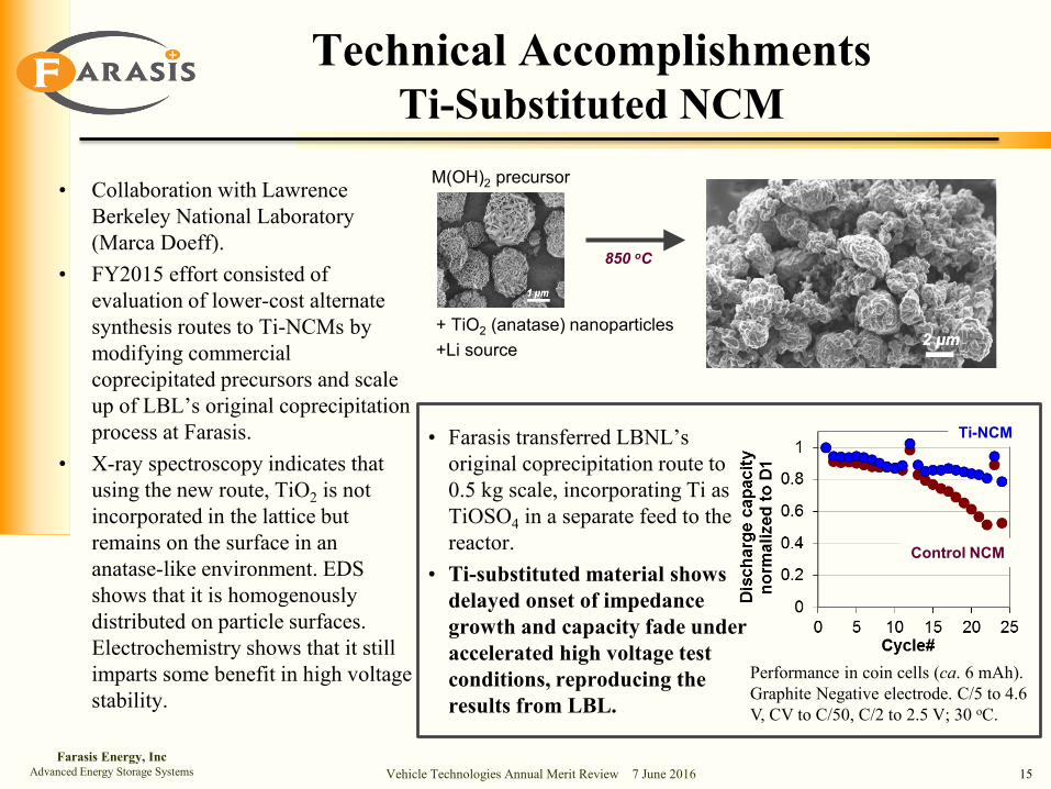
• Collaboration with LawrenceBerkeley National Laboratory(Marca Doeff).
• FY2015 effort consisted ofevaluation of lower-cost alternatesynthesis routes to Ti-NCMs bymodifying commercialcoprecipitated precursors and scaleup of LBL’s original coprecipitationprocess at Farasis.
• X-ray spectroscopy indicates thatusing the new route, TiO2 is notincorporated in the lattice butremains on the surface in ananatase-like environment. EDSshows that it is homogenouslydistributed on particle surfaces.Electrochemistry shows that it stillimparts some benefit in high voltagestability.
+ TiO2 (anatase) nanoparticles+Li source
M(OH)2 precursor
850 oC
Control NCM
Ti-NCM
Performance in coin cells (ca. 6 mAh). Graphite Negative electrode. C/5 to 4.6 V, CV to C/50, C/2 to 2.5 V; 30 oC.
• Farasis transferred LBNL’soriginal coprecipitation route to0.5 kg scale, incorporating Ti asTiOSO4 in a separate feed to thereactor.
• Ti-substituted material showsdelayed onset of impedancegrowth and capacity fade underaccelerated high voltage testconditions, reproducing theresults from LBL.
Farasis Energy, IncAdvanced Energy Storage Systems Vehicle Technologies Annual Merit Review 7 June 2016 16
Technical AccomplishmentsIon-Exchanged LMR-NCM
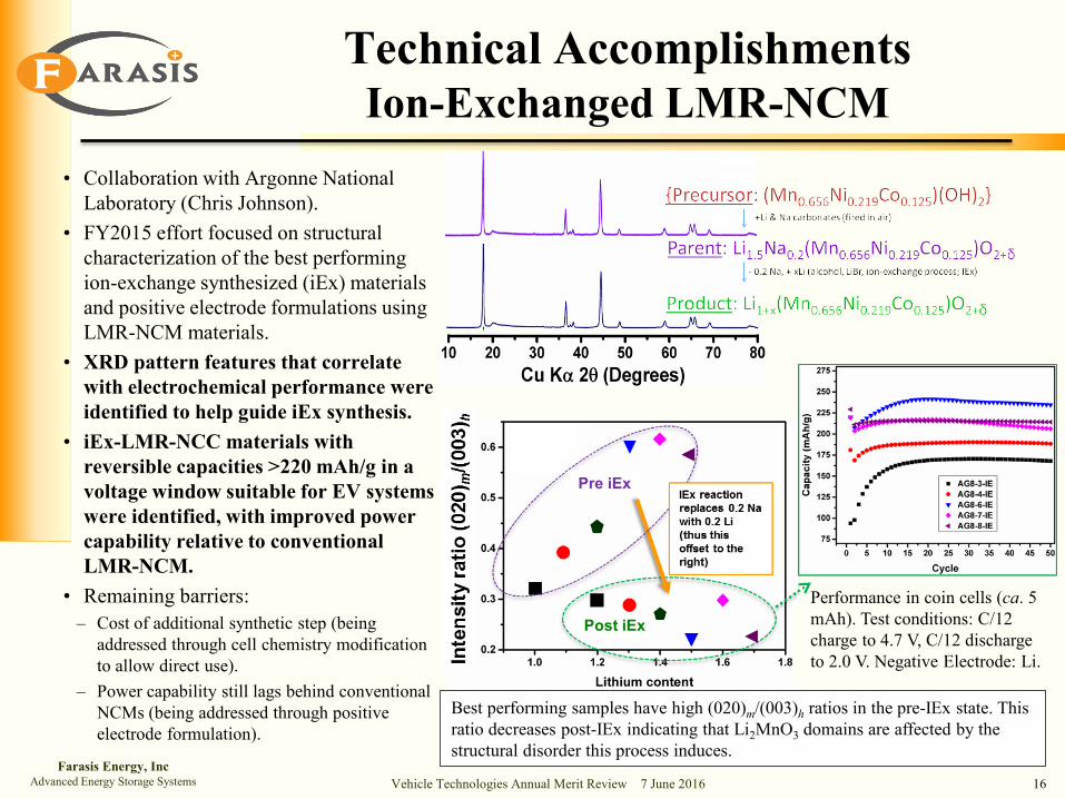
• Collaboration with Argonne NationalLaboratory (Chris Johnson).
• FY2015 effort focused on structuralcharacterization of the best performingion-exchange synthesized (iEx) materialsand positive electrode formulations usingLMR-NCM materials.
• XRD pattern features that correlatewith electrochemical performance wereidentified to help guide iEx synthesis.
• iEx-LMR-NCC materials withreversible capacities >220 mAh/g in avoltage window suitable for EV systemswere identified, with improved powercapability relative to conventionalLMR-NCM.
• Remaining barriers:– Cost of additional synthetic step (being
addressed through cell chemistry modificationto allow direct use).
– Power capability still lags behind conventionalNCMs (being addressed through positiveelectrode formulation).
Performance in coin cells (ca. 5 mAh). Test conditions: C/12 charge to 4.7 V, C/12 discharge to 2.0 V. Negative Electrode: Li.
Post iEx
Pre iEx
Best performing samples have high (020)m/(003)h ratios in the pre-IEx state. This ratio decreases post-IEx indicating that Li2MnO3 domains are affected by the structural disorder this process induces.

Farasis Energy, IncAdvanced Energy Storage Systems Vehicle Technologies Annual Merit Review 7 June 2016 17
Technical AccomplishmentsGen1 Cell Build Ongoing Testing
Gen1 cell testing: Small pouch cells (ca. 1.4 Ah): NCM//graphite. Test conditions: C/3 charge to 4.4 V, C/3 discharge to 3.0 V; one C/20 cycle every 21 cycles; 30 oC.
Nonfluorinated BaselineFluorinated – F25Fluorinated - F22
Stabilized NCMPristine NCM
• Some Gen1 cells, started in FY2014, are still on test (> 80 % initial capacity).• Cells were also evaluated under accelerated failure testing conditions (higher temperatures,
higher upper cutoff voltage, CV charging) and maintain the same relative capacity-retention ordering.
• Positive impact of fluorinated electrolyte is less prevalent in cells with stabilized NCM.• Fluorinated electrolytes can improve cycle life ...but can also lead to early failure. In some
cases this is due to gas generation.

Farasis Energy, IncAdvanced Energy Storage Systems Vehicle Technologies Annual Merit Review 7 June 2016 18
ca. 2 Ah Small Pouch Cell (new format)Stabilized HV NCMGraphite
ca. 250 mAh Small Pouch Cell (3-layer)HV Stabilized NCMs/LMR-NCMsGraphite, 8% & 16 % SiNANOde
Baseline (LiPF6 in EC/EMC)Multiple fluorinated solvent electrolytesMultiple additives
PHEV Cell Design:Materials:
EV Cell Design:Materials:
Electrolytes:
• The Gen 2 PHEV cell was implemented in a redesigned form factor to increase actual energy density of small pouch cell.
• Extensive electrolyte screening was performed.• Gen 2 EV cells were tested in smaller form factor due to material availability constraints of
high Si content material.
Technical AccomplishmentsGeneration 2 Cell Build
Gen2 PHEV cell

Farasis Energy, IncAdvanced Energy Storage Systems Vehicle Technologies Annual Merit Review 7 June 2016 19
Technical Accomplishments:Gen2 PHEV Cell Electrolyte Development
• Electrolyte development in Gen 2PHEV cell was conducted in 2 phases,screening different fluorinated solventsystems and additive packages.
• Using the same additive package, gasgenerated during formation is similarfor non-fluorinated and fluorinatedsolvent systems, but fluorinatedelectrolyte solvents tend to producemore gas during long term cycling.
• The best fluorinated solventsystems extend cycle life by ca. 50%over nonfluorinated systems thatuse the same additives.
Gen2 PHEV accelerated testing cell performance: Small pouch cells (ca. 2 Ah); two cells of each design. Test conditions: C/2 CCCV charge to 4.5 V, C/100 cutoff, 1C discharge to 3.0 V; 30 oC. RPTconsists of HPPC & CP measurements every 50 cycles.
CP cycles
F25+1%A+2%B
F25+2%B
F25+1%A
Nonfluorinatedbaseline (+A&B)
F25
Gas generated during:Formation Cycle Life
HPPC cycles

Farasis Energy, IncAdvanced Energy Storage Systems Vehicle Technologies Annual Merit Review 7 June 2016 20
Technical Accomplishments:Gen2 EV Cell Development
• High Energy Positive Electrodes weredeveloped with useable reversible capacities1.2 – 1.4x that of a baseline NCM.
• Capacity fade in Si containing cells islargely due to continual SEI growth andelectrolyte consumption.
• High energy positive and negativeelectrode materials were integrated in thefinal EV deliverable build.
Spec
ific
Cap
acity
(Rel
ativ
e)
Baseline NCM
HE
form
ulat
ions
High-Energy Positive Electrode Development
Gen2a EV Cell Testing
Gen2b EV Cell Testing
Gen2 EV cell testing: Small pouch cells (ca. 250 mAh). Positive Electrodes: HV NCMs/LMR-NCMs.
Coin cell testing (6 mAh); Li metal negative electrode.Normalized to baseline NCM performance.
Fixed HV/HE positive electrode composition.Negative electrode comparison.
Fixed 8 % Si composite negative electrode.Positive electrode comparison.
Graphite (control)Negative Electrode
16 % SiNegative Electrode
Positive Electrode 1Positive Electrode 2
Positive Electrode 3

Farasis Energy, IncAdvanced Energy Storage Systems Vehicle Technologies Annual Merit Review 7 June 2016 21
Technical AccomplishmentsProject Cell Build Summary
• Gen1 cell build explored diverse chemistry and provided experience to guide the Gen 2 cell build and testing.
• Gen2 cell build provided input for final refinements of deliverable PHEV and EV cell designs.
• EV cell design is still somewhat limited by poor cycle life of Si anodes.• Deliverable cell builds targeting PHEV and EV system performance
goals utilized advanced positive and negative electrode active materials and fluorinated electrolytes developed in this program.

Farasis Energy, IncAdvanced Energy Storage Systems Vehicle Technologies Annual Merit Review 7 June 2016 22
Responses to Reviewer Comments
• In FY2015 project was reviewed favorably.
• Most poignant comments and our responses:
Reviewer Comment Response
“Overall approach is focused on energy; power / rate performance improvement needed as well.”
In general, energy targets are harder to meet. Experimental test protocols include impedance analysis (HPPC, EIS, etc.) to ensure sufficient power capability.
“... the anode side ... is focused on only one development route that has even lower scientific support [than the cathode strategy]. That route might be a small weakness”“It is recommended to intensify the work on [the Si anode part of the project]”“Cooperation could have been strengthened by including a partner for a second Si material source or detailed analysis.”
These projects are of limited scope by necessity. As suggested, Farasis intensified research on Si negative electrode technology in the second year through the end of the project.
“No information given regarding changes leading to improvements in electrolyte technology.”
We have included information regarding specific factors in electrolyte development.
OVE
RAL
LSI
LIC
ON
ELEC
TRO
LYTE

Farasis Energy, IncAdvanced Energy Storage Systems Vehicle Technologies Annual Merit Review 7 June 2016 23
Collaborations and Coordination with Other Institutions
Argonne National Laboratory (Chris Johnson, Eungje Lee, Arturo Gutierrez)Federal Laboratory – Subcontractor providing materials and analytical work for project.• Layered-Layered-(Spinel) (LL-S) NCM Cathode Material Development – Developing an ion-
exchange synthetic approach to address the impedance and voltage fade barriers of high capacity LL-NCM cathode materials.
Lawrence Berkeley National Laboratory (Marca Doeff, Fen Lin):Federal Laboratory – Subcontractor providing materials and analytical work for project.• High Voltage Stabilized NCM Cathode Material Development – Develop and optimize doping
and advanced coating methods to stabilize high capacity NCM materials to operation at high voltages.
Nanosys/OneD Material, LLC (Yimin Zhu):Industry – Subcontractor providing materials and development guidance for project.• Nano-Silicon Graphite Composite Anode Material Development – Optimize nano-silicon
graphite composites for long term cycling stability.
DuPont (Srijanani Bhaskar):Industry – Partner providing materials and analytical work for project.• High Voltage Capable Electrolytes and Cell Components- Develop new fluorinated electrolyte
systems, additives and separators with exceptional high voltage stability to advanced active materials.

Farasis Energy, IncAdvanced Energy Storage Systems Vehicle Technologies Annual Merit Review 7 June 2016 24
Proposed Future Work
• Project is complete.
• Continued Technology Development at Farasis.– Increase Si content in negative electrode to push towards higher energy
densities.
– Continue electrolyte development for higher Si content electrodes.
– Trickle down technology: Technologies developed in this project have been implemented in prototypes up to 10 Ah, targeting near term commercialization in niche markets.

Farasis Energy, IncAdvanced Energy Storage Systems Vehicle Technologies Annual Merit Review 7 June 2016 25
Summary Slide
• Project goal is the development of high energy Li-ion cells capable of meeting the PHEV40 and EV performance goals set by DOE.
• Our approach to addressing current cell level performance barriers is based on advanced materials with a strong technical foundation.
– Improvements in capacity and rate capability were achieved for “layered-layered” cathode materials synthesized via the ion-exchange synthetic route.
– Bulk-doping of NCM materials with Ti improves stability when cycling at high voltage.
– Novel high voltage electrolytes improve long term high voltage operation.
• Strong coordination with subcontractors and partners has allowed parallel development of multiple cell components and incorporation into high performance cells.
• The final phase of the project focused on final optimizations of deliverables.
• The project has significantly advanced the TRL for these technologies.