high capacity chiller systems - aqua-air · high capacity chiller systems. 20 ton chillers. a20-1e...
TRANSCRIPT

High CapacityChiller Systems

20 TonChillers

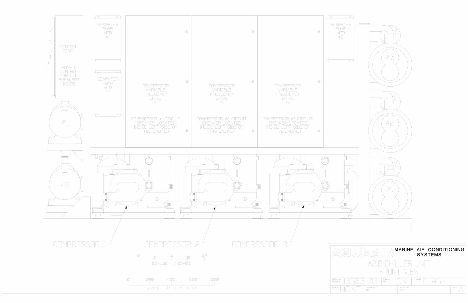
A20-1E20 Ton ( 240,000 BTU/H )
Single Stage Open Drive CompressorCustom designed for use by the
Brazilian Navy2 Units / Frigate

AQ-24020 Ton ( 240,000 BTU/H )
2 Stage Semi-hermetic Compressors

30 TonChillers

AV30P3-1VHD30 Ton ( 360,000 BTU/H )
3x10 Ton AC10HD Series Chillerswith Integral Chillwater Pump

40 TonChillers
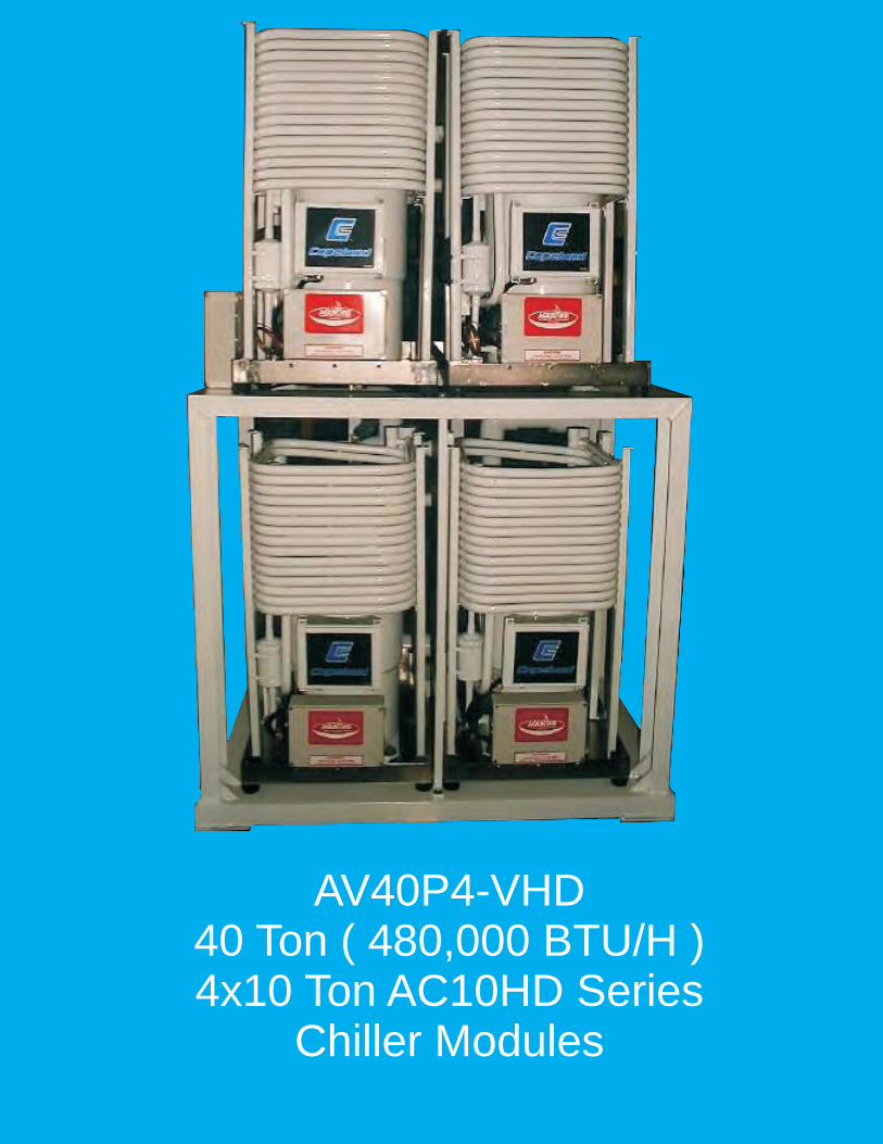
AV40P4-VHD40 Ton ( 480,000 BTU/H )4x10 Ton AC10HD Series
Chiller Modules

OM40-2VIHD40 Ton ( 480,000 BTU/H )
2 Stage Semi-hermetic CompressorsIntegral Immersion heater
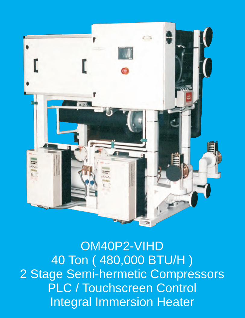
OM40P2-VIHD40 Ton ( 480,000 BTU/H )
2 Stage Semi-hermetic CompressorsPLC / Touchscreen ControlIntegral Immersion Heater

60 TonChillers

AV60P6-2VHGD 60 Ton Rack Chiller Unit
Aqua-Air Manufacturing 1050 E. 9th Street, Hialeah, FL 33010 USAToll Free 800-328-1043 Phone 305-884-8363 Fax 305-883-8549
www.aquaair.com Email: [email protected]

Specifications
Cooling Capacity 60 tons, 720,000 BTU/HHeating Capacity Reverse cycle, 900,000 BTU/HModules 6 x 120,000 BTU/H Alpha Series ChillersDimensions 53" deep x 76" wide x 75" highPower 208-3-60Current draw 186 amps at 208-3-60Power draw 59321 wattsRefrigerant R-407C (Environmentally Friendly)Chillwater Connections 4" Flange Inlet & OutletSeawater Connections 4" Flange Inlet & OutletCompressors Copeland Scroll, 10 ton eachControl PLCInterface TouchscreenDrives 6 x 15 HP Variable Frequency Drives for Surgeless Start
1 x 5 HP VFD for modulation of the Seawater PumpCircuit breakers 6-Compressor, 1-C/W Pump, 1-S/W Pump, 1-Control CircuitMaterials Frame-Steel, Drain pans-Stainless Steel (coated internally)Paint Awlgrip Matterhorn WhiteChillwater Pump Integral (2) XT200I-50-50F, 5 HP eachFlow Switch Mounted on chillwater inlet line

AQ-72060 Ton ( 720,000 BTU/H )
4 Stage Semi-hermetic Compressors

A60P4-VIHD60 Ton (720,000 BTU/H)
4 Stage, Semi-hermetic CompressorsPLC / Touchscreen ControlVariable Frequency DrivesIntegral Immersion Heater

CHILLER UNIT SPECIFICATION
OM60-4VIHD
COOLING CAPACITY: 60 tons [ 720,000 BTU/H ] [ 180,000 KCAL/H ] at 45/F ( 7.2/ C ) leaving water temperature and 55/ F ( 12.8/ C ) returning watertemperature. Chiller unit flow rate will be approximately 180 gpm. Condenser flowrate ( each ) is to be approximately 60 gpm entering at a maximum temperature of90/ F ( 32/ C ). All ratings are at a fouling factor of 0.0005 .
HEATING CAPACITY: 54 Kw [ 184,410 BTU/H ] [ 46,103 KCAL/H ] of totalheating capacity at 120/ F ( 48.9/ C ) leaving water temperature and 100/ F ( 37.8/ C ) returning water temperature.
CONSTRUCTION & RATINGS: The chiller unit shall be constructed inaccordance with ARI Standard 590-86 and shall comply with all applicable NEC andASME codes for water cooled chillers.
COMPRESSORS: The chiller unit will have four, 15 ton Bitzer semi-hermeticcompressors. Each compressor will be equipped with suction and discharge valves.Input voltage to the compressor motor will be 208-3-60. Power consumption of eachcompressor is approximately 14.1 kW each. Refrigerant to be used is R-22 .
CAPACITY CONTROL: Chiller unit capacity control will be achieved throughthe use of four variable frequency drive ( VFD ) units, one for each compressor. TheVFD will vary the compressor motor speed from a maximum of 100% of capacity toa minimum of 70%. The VFD requires an input power supply of 208-3-60. Themaximum output power will be 208-3-60 to the compressor motor. The VFD outputwill be regulated by a 4-20ma signal to the VFD from the PLC. The VFDvoltage/frequency output will be varied based upon chilled water outlet temperature.The VFD will also control the compressor motor so that there is no current inrush,during starting, above the motor's standard running amperage.
COOLER: The unit is equipped with four plate style heat exchangers, each of15 tons capacity. Each plate heat exchanger has a single water and refrigerantcircuit. Construction of the unit is of #316 stainless steel. The material used to brazethe plates together is copper. Maximum test pressure for both circuits is 635 psig.Each plate will be individually insulated with 1/2" thick closed cell insulation.

CONDENSER: The unit is equipped with four shell and tube marinecondensers. The shell is constructed of ASME spec SA-53 steel pipe. Shells areshot blasted and cleaned before assembly. Tubes are high performance enhancedsurface seamless 90/10 Cupro-Nickel tubes to ASME spec SB-359. Tubes are rollerexpanded into double grooved tubesheets to assure tight joints. Tubesheets are90/10 Cupro-Nickel to ASME spec SB-171 Alloy 706. Tube supports are quality steelplug welded to the shell. Heads are cast bronze with integral pass partitions, ASMEspec SB-62. Gaskets are die-cut providing effective sealing between tubesheets andmachined heads. The refrigerant side is constructed and tested in accordance withSection VIII, Division 1 of ASME Code for unfired pressure vessels. Shell sidedesign pressure ( refrigerant side ) is 350 psig at 250/ F. Tube side ( water side ) is150 psig at 150/ F. Every condenser is tested per ASME Code prior to shipment.Seawater connections are 2" Class 150 PVC schedule 80 flanges. Water flow to thecondenser will be regulated by a compressor discharge pressure actuated waterregulating valve. A pressure relief valve ( set for 350 psig ) on the shell is standard.
IMMERSION HEATER ELEMENTS: The unit is equipped with a three stage,18 element, 54 Kw 5" flange style immersion heating element. The heater elementsare rated at full wattage on 208-3-60 power input. The elements are constructed ofcopper with a maximum watt density of 50 watts per square inch. The elementheater tank will be constructed of steel pipe to ASME specifications. All welds willbe by MIG welding procedure. The tank will be equipped with a 5" 150lb ANSI raisedface welding neck flange to accept the 5" flange style immersion heater. The tankdesign rating pressure is 150 psig at 200/ Fahrenheit. The tank will be equipped witha ASME water pressure relief valve.
REFRIGERANT CIRCUIT: Each of the four refrigerant circuits shall include a
discharge line check valve, liquid line ball valve, replaceable core liquid line filterdrier with access fitting for refrigerant charging, combination moisture indicator andsight glass, liquid line solenoid and thermal expansion valve. All suction lines will becovered with a minimum of 1/2" closed cell insulation.
CONTROL PANEL / ELECTRICAL BOX: The unit will have a NEMA 12 typeenclosure for all of the electrical components. The chiller unit will be controlled bya programmable logic controller ( PLC ). The user interface for this PLC will consistof a touch screen mounted on the front of the electrical box. This touch screen willperform the following switching functions:
System mode switchCompressor On-Off switch ( 4 )Heating stage On-Off Switch ( 3 )
AQUA-AIR MANUFACTURING, division of the James D. Nall Co., Inc.1050 East 9th Street, Hialeah, Florida 33010 U.S.A.
Ph. 305-884-8363 Fax 305-883-8549 E-mail [email protected]
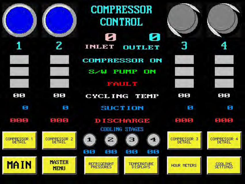
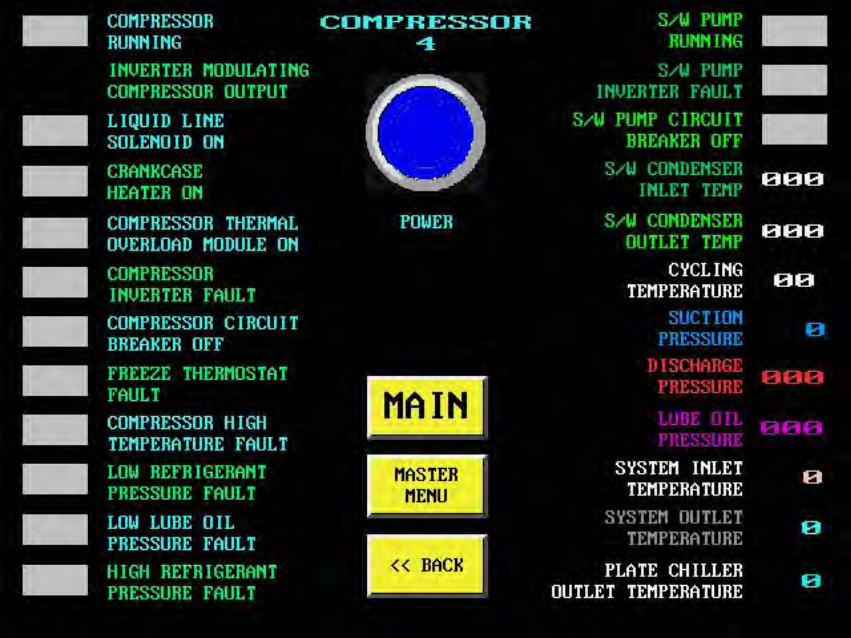
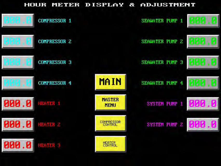
The touch screen will also display the following information
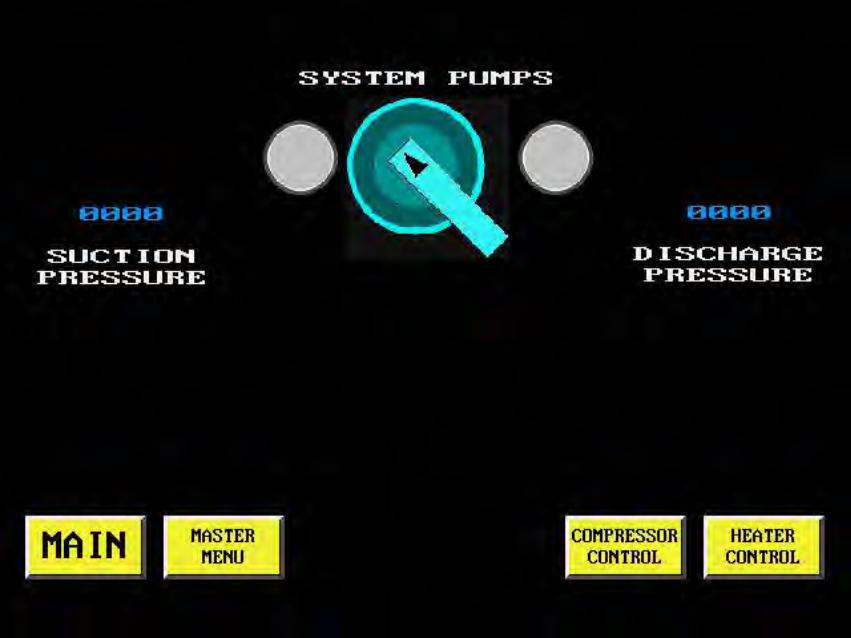
Digital refrigerant pressure readouts ( suction and discharge ) for eachcompressor
Digital temperature display, in Fahrenheit, for the chillwater inlet and outlettemperatures
Elapsed time meters showing the run times for all compressors, pumpsand heater stagesChillwater pump motor fault indicationCompressor inverter operational ( 4 )Cooling stage engaged ( 4 )Cooling modeChiller freeze thermostat engagedLow chillwater flow through the chiller Low compressor refrigerant pressure ( 4 )High compressor refrigerant pressure ( 4 )Compressor motor overload ( 4 )High compressor discharge temperature ( 4 )Compressor inverter fault indicator ( 4 )Heating modeHeating stage engaged ( 3 )
A phone communication modem will be included that will allow the PLC to beaccessed remotely for diagnostic purposes.
Circuit breakers will be provided for the compressors ( 4 ), seawater pumps ( 4 ), heater stages ( 3 ), chillwater pump and control circuitry. All wiring on the unitexternal to the electrical box will be enclosed in liquid-tite conduit or other approvedprotective sheathing.
FRAME: The frame for the unit will be constructed of appropriately sized steel
channel, square tube and angle. All welds will be by MIG welding procedure.Completed frame will be primed with a red lead based primer and then painted tomeet 500 hour salt spray requirement. Paint to be used will be Awlgrip MatterhornWhite. Stainless steel drain pans with a non-corrosive internal coating will beinstalled under any condensate producing components.
i:\wordpfct\OM604VIHD\OM604VIH.wpd


1
CHILLER UNIT SPECIFICATION
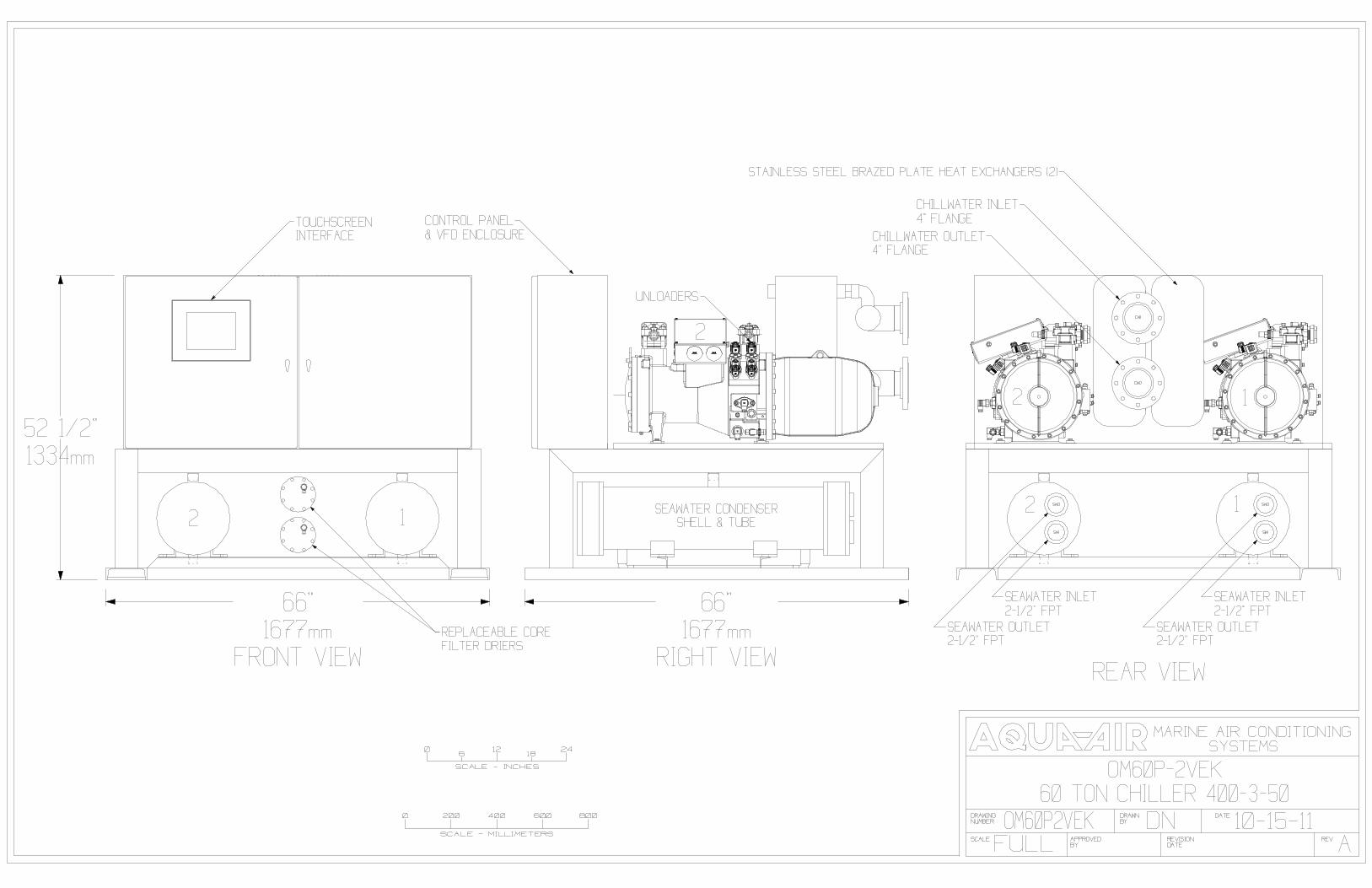
OM60P-2VEKCOOLING CAPACITY: 60 tons ( 720,000 BTU/H ) { 211 kW } at 45/ F { 7.2/ C } leaving watertemperature and 55/ F { 12.8/ C } returning water temperature. Chiller unit flow rate will beapproximately 180 gpm { 41 m3h }. Condenser flow rate ( each ) is to be approximately 120gpm { 27 m3h } entering at a maximum temperature of 90/ F { 32/ C }. All ratings are at afouling factor of 0.0005
CONSTRUCTION & RATINGS: The chiller unit shall be constructed in accordance with ARIStandard 590-86 and shall comply with all applicable NEC and ASME codes for water cooledchillers.
COMPRESSORS: The chiller unit will have two, 30 ton {155 kW}Bitzer semi-hermetic compact screw compressors. Eachcompressor will be equipped with suction and discharge valves.Input voltage to the compressor motor will be 400-3-50. This willbe achieved through the use of Variable Frequency Drives. Powerconsumption of each compressor is approximately 28 kW each.Refrigerant to be used is R-407C .
CAPACITY CONTROL: Infinite capacity control of each compressorwill be achieved through the use of four unloaders on each compressor.These unloaders will be regulated by the PLC to maintain a consistentset point under changing load conditions. The unloaders will also allowthe compressor to be started unloaded.Each compressor will be connected to a Variable Frequency Drive(VFD). The VFD will control the compressor motor so that there is nocurrent inrush, during starting, above the motor's standard runningamperage. The VFD requires an input power supply of 400-3-50. Themaximum output power will be 400-3-00 to the compressor motor. TheVFD’s will be located in a dedicated cabinet that is environmentallymaintained at 80/ F {26.6/ C} under all conditions.
COOLER: The unit is equipped with two plate style heat exchangers,each of 30 tons {155 kW} capacity. Each plate heat exchanger has asingle water and refrigerant circuit. Construction of the unit is of #316stainless steel. The material used to braze the plates together is copper.Maximum test pressure for both circuits is 635 psig. Each plate will beindividually insulated with 1/2" {13mm} thick closed cell insulation. Waterflow through each plate will be 108 gpm { 24.5 m3h } at a pressure dropof 7.20 psi {0.50 bar }. The water in the chillwater loop will require a 20%glycol mixture. A stainless steel drain pan will be mounted under theplates to catch any associated condensation.

2
CONDENSER: The unit is equipped with two shell and tube marine condensers. The shell isconstructed of ASME spec SA-53 steel pipe. Shells are shot blasted and cleaned beforeassembly. Tubes are high performance enhanced surface seamless 90/10 Cupro-Nickel tubesto ASME spec SB-359. Tubes are roller expanded into double grooved tubesheets to assuretight joints. Tubesheets are 90/10 Cupro-Nickel to ASME spec SB-171 Alloy 706. Tubesupports are quality steel plug welded to the shell.Heads are cast bronze with integral pass partitions,ASME spec SB-62. Gaskets are die-cut providingeffective sealing between tubesheets and machinedheads. The refrigerant side is constructed and tested inaccordance with Section VIII, Division 1 of ASME Codefor unfired pressure vessels. Shell side design pressure( refrigerant side ) is 350 psig at 250/ F. Tube side ( water side ) is 150 psig at 150/ F. Everycondenser is tested per ASME Code prior to shipment. Seawater connections are 2-1/2" NPT.Water flow to the condenser will be regulated by using VFD’s to modulate the speed of theseawater pumps based upon the individual compressor discharge pressure. This provides forless system erosion and better discharge pressure control. It also eliminates the large brasswater regulating valves that are inherently problematic in the seawater circuit. A pressure reliefvalve ( set for 350 psig ) on the shell is standard.
REFRIGERANT CIRCUIT: Each of the two refrigerant circuits shall includea liquid line ball valve, replaceable core liquid line filter drier with access fittingfor refrigerant charging, combination moisture indicator and sight glass,refrigerant pressure transducers and thermal expansion valve. All suctionlines will be covered with a minimum of 1/2" closed cell insulation. Allrefrigerant pressure transducers, switches and controls will be installed withisolation valves. The system will utilize Electronic Expansion Valves forprecise refrigerant metering to the evaporators under all conditions.
CONTROL PANEL / ELECTRICAL BOX: The unit will have a NEMA12 type enclosure for all of the electrical components. The chiller unitwill be controlled by a Programmable Logic Controller ( PLC ). Theuser interface for this PLC will consist of a touchscreen mounted onthe front of the electrical box. This touchscreen will perform thefollowing main switching functions in addition to numerous other minorcontrols:
System On-Off SwitchCompressor On-Off Switch ( 2 )Chillwater Pump Selector Switch (Primary/Secondary)
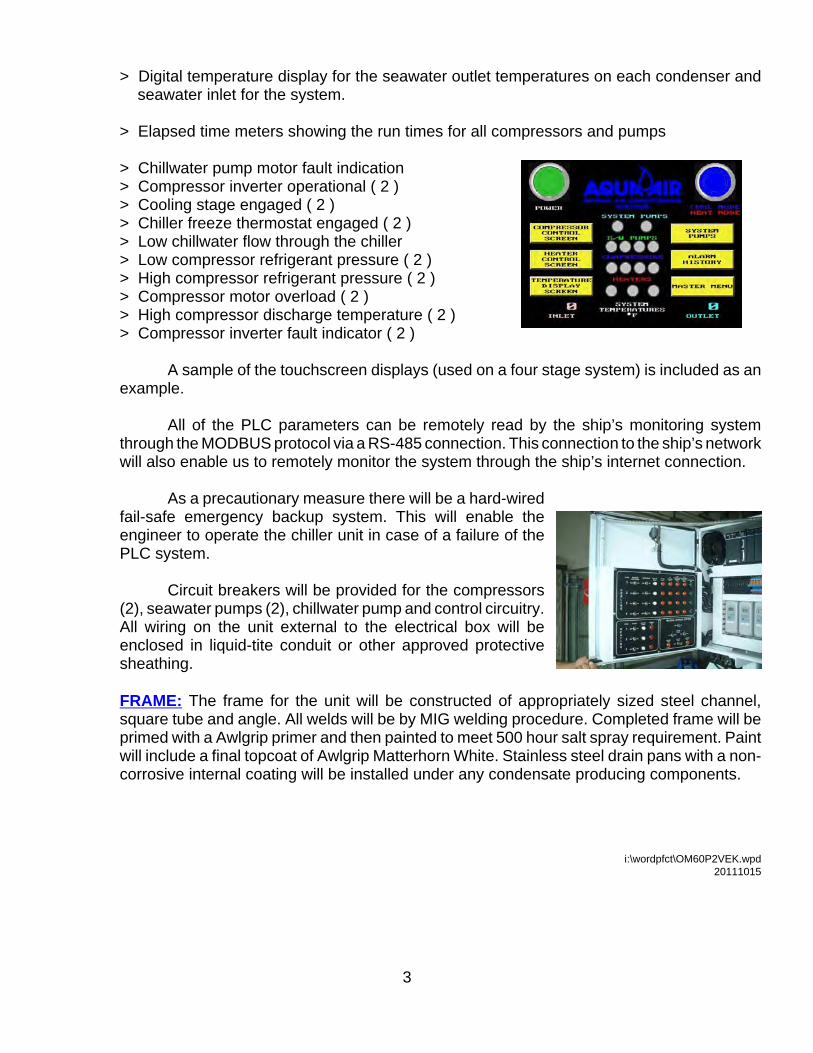
The touch screen will also display the following information
> Digital refrigerant pressure readouts ( suction and discharge ) for each compressor> Digital temperature display for the chillwater inlet and outlet temperatures
3
> Digital temperature display for the seawater outlet temperatures on each condenser and seawater inlet for the system.
> Elapsed time meters showing the run times for all compressors and pumps
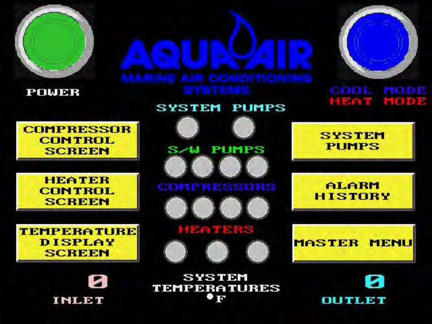
> Chillwater pump motor fault indication> Compressor inverter operational ( 2 )> Cooling stage engaged ( 2 )> Chiller freeze thermostat engaged ( 2 )> Low chillwater flow through the chiller > Low compressor refrigerant pressure ( 2 )> High compressor refrigerant pressure ( 2 )> Compressor motor overload ( 2 )> High compressor discharge temperature ( 2 )> Compressor inverter fault indicator ( 2 )
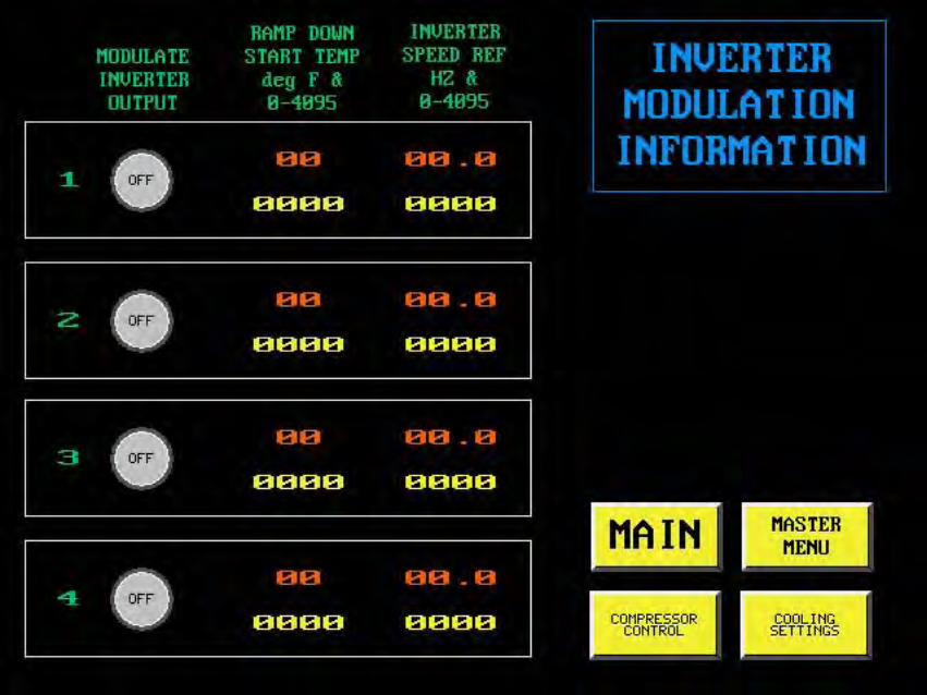
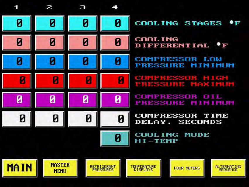
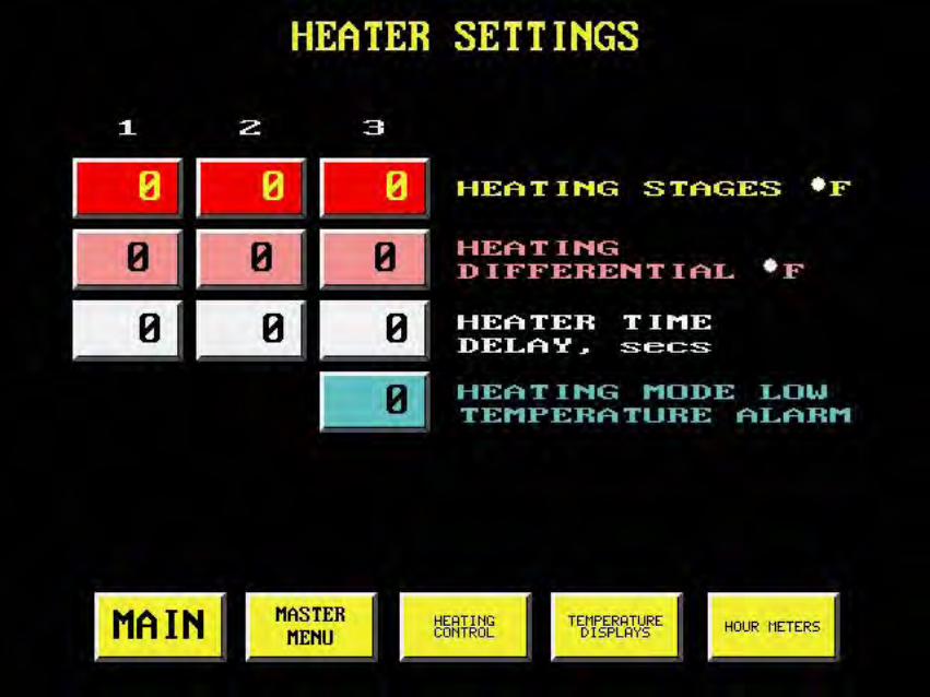
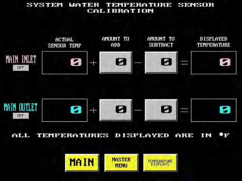
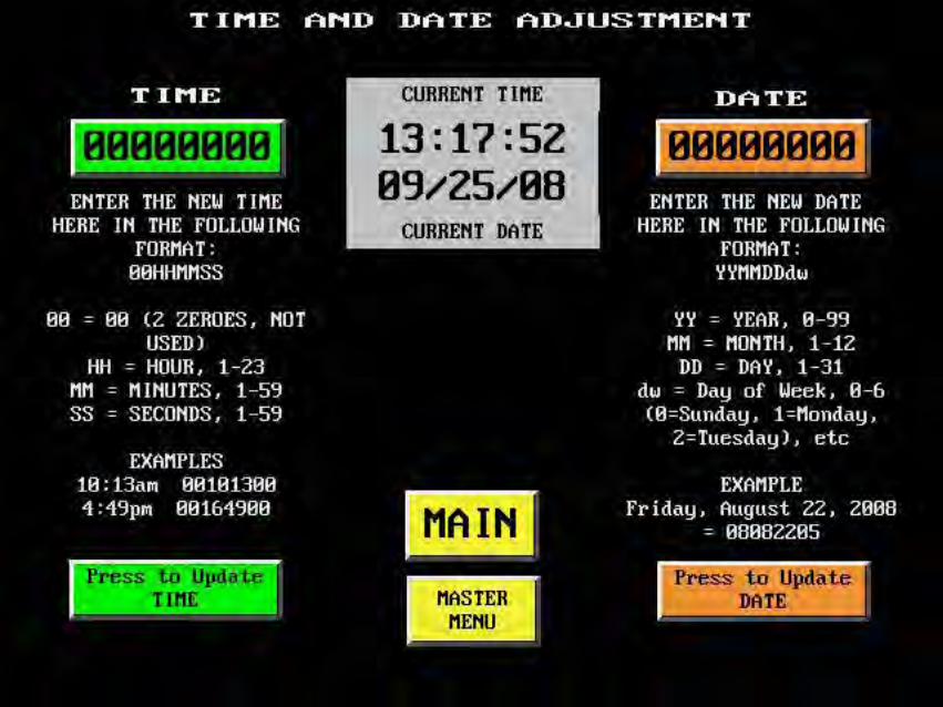
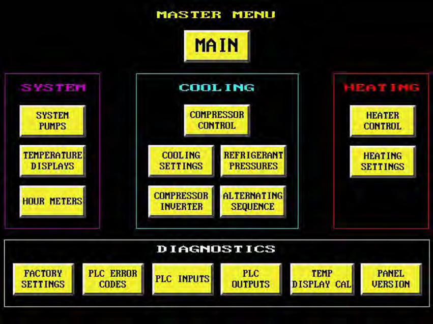
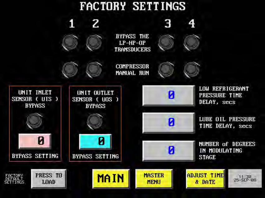
A sample of the touchscreen displays (used on a four stage system) is included as anexample.
All of the PLC parameters can be remotely read by the ship’s monitoring systemthrough the MODBUS protocol via a RS-485 connection. This connection to the ship’s networkwill also enable us to remotely monitor the system through the ship’s internet connection.
As a precautionary measure there will be a hard-wiredfail-safe emergency backup system. This will enable theengineer to operate the chiller unit in case of a failure of thePLC system.
Circuit breakers will be provided for the compressors(2), seawater pumps (2), chillwater pump and control circuitry.All wiring on the unit external to the electrical box will beenclosed in liquid-tite conduit or other approved protectivesheathing.
FRAME: The frame for the unit will be constructed of appropriately sized steel channel,square tube and angle. All welds will be by MIG welding procedure. Completed frame will beprimed with a Awlgrip primer and then painted to meet 500 hour salt spray requirement. Paintwill include a final topcoat of Awlgrip Matterhorn White. Stainless steel drain pans with a non-corrosive internal coating will be installed under any condensate producing components.
i:\wordpfct\OM60P2VEK.wpd20111015

75 TonChillers

OM75P-4VIHD 75 ton Chiller
In April of 2008, Aqua Air Manufacturing was commissioned by the owners of a 172' motoryachtto provide a replacement chiller for the existing 15 year old Aqua-Air AQ900HD 75 ton, 4 stage chiller unit.
Aqua-Air has project records dating back to the early 1980's detailing the equipmentthat we have supplied for all of our largeprojects. One of the requirements of thisproject was for the chiller to fit in the sameexact position and connect up to theexisting chillwater piping. With ourextensive CAD drawings for this project itwas very easy to be assured this unit wouldfit exactly! The Omega Series OM75P-4VIHD Chiller Unit is the culmination of many yearsexperience in the design and manufactureof large tonnage yacht chiller systems.
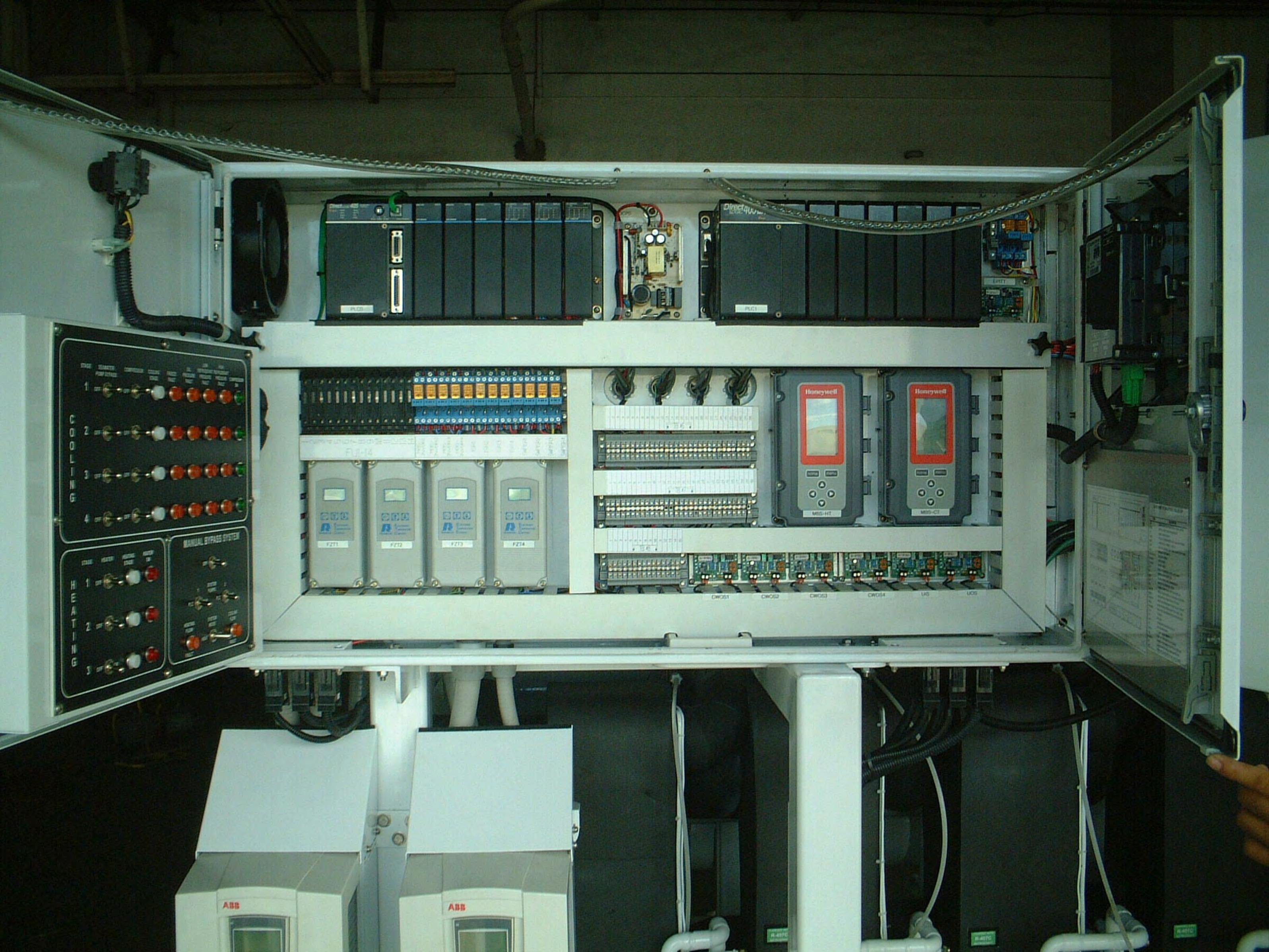
Some of the OM75P-4VIHD notable features are semi-hermetic compressors, stainless steel plate heat exchangers, shell and tubecondensers, variable frequency drives forcompressors and seawater pumps, threestage immersion heater, touchscreen controlinterface, PLC control and remotemonitoring capability.
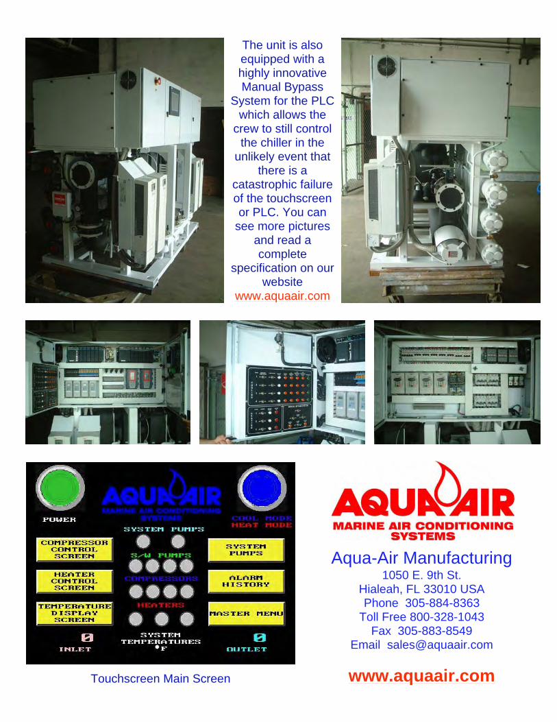
The unit is also equipped with a highly innovative Manual Bypass
System for the PLC which allows the
crew to still control the chiller in the
unlikely event that there is a
catastrophic failure of the touchscreen or PLC. You can
see more pictures and read a complete
specification on our website
www.aquaair.com
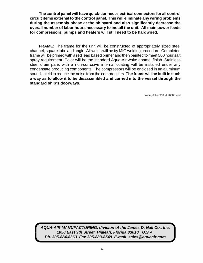
Touchscreen Main Screen
Aqua-Air Manufacturing 1050 E. 9th St.
Hialeah, FL 33010 USA Phone 305-884-8363
Toll Free 800-328-1043 Fax 305-883-8549
Email [email protected]
www.aquaair.com

1
CHILLER UNIT SPECIFICATION
OM75P-4VIHD
COOLING CAPACITY: 75 tons [ 900,000 BTU/H ] at 45/ F leaving watertemperature and 55/ F returning water temperature. Chiller unit flow rate will beapproximately 225 gpm. Condenser flow rate ( each ) is to be approximately 75 gpmentering at a maximum temperature of 90/ F. All ratings are at a fouling factor of 0.0005.
HEATING CAPACITY: 42 Kw [ 143,430 BTU/H ] of total heating capacity at 120/F leaving water temperature and 100/ F returning water temperature.
CONSTRUCTION & RATINGS: The chiller unit shall be constructed in accordancewith ARI Standard 590-86 and shall comply with all applicable NEC and ASME codesfor water cooled chillers. The entire unit will be constructed in such a way that it canbe disassembled at the job site, carried into the vessel and reassembled in place.Instructions for the recommended disassembly method will be included.
COMPRESSORS: The chiller unit will have four, 18.75 ton Bitzer semi-hermeticcompressors. Each compressor will be equipped with suction and discharge valves.Input voltage to the compressor motor will be 208-3-60. Power consumption of eachcompressor is approximately 16 kw each. Refrigerant to be used is R-22 .
CAPACITY CONTROL: Chiller unit capacity control will be achieved through theuse of four variable frequency drive ( VFD ) units, one for each compressor. The VFDwill vary the compressor motor speed from a maximum of 100% of capacity to aminimum of 70%. The VFD requires an input power supply of 208-3-60. The maximumoutput power will be 208-3-60 to the compressor motor. The VFD output will beregulated by a 4-20ma signal to the VFD from the PLC. The VFD voltage/frequencyoutput will be varied based upon chilled water outlet temperature. The VFD will alsocontrol the compressor motor so that there is no current inrush, during starting, abovethe motor's standard running amperage.
COOLER: The unit is equipped with four plate style heat exchangers, each of 18.75tons capacity. Each plate heat exchanger has a single water and refrigerant circuit.Construction of the unit is of #316 stainless steel. The material used to braze the platestogether is copper. Maximum test pressure for both circuits is 635 psig. Each plate willbe individually insulated with 1/2" thick closed cell insulation.
2
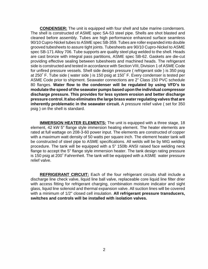
CONDENSER: The unit is equipped with four shell and tube marine condensers.The shell is constructed of ASME spec SA-53 steel pipe. Shells are shot blasted andcleaned before assembly. Tubes are high performance enhanced surface seamless90/10 Cupro-Nickel tubes to ASME spec SB-359. Tubes are roller expanded into doublegrooved tubesheets to assure tight joints. Tubesheets are 90/10 Cupro-Nickel to ASMEspec SB-171 Alloy 706. Tube supports are quality steel plug welded to the shell. Headsare cast bronze with integral pass partitions, ASME spec SB-62. Gaskets are die-cutproviding effective sealing between tubesheets and machined heads. The refrigerantside is constructed and tested in accordance with Section VIII, Division 1 of ASME Codefor unfired pressure vessels. Shell side design pressure ( refrigerant side ) is 350 psigat 250/ F. Tube side ( water side ) is 150 psig at 150/ F. Every condenser is tested perASME Code prior to shipment. Seawater connections are 2" Class 150 PVC schedule80 flanges. Water flow to the condenser will be regulated by using VFD’s tomodulate the speed of the seawater pumps based upon the individual compressordischarge pressure. This provides for less system erosion and better dischargepressure control. It also eliminates the large brass water regulating valves that areinherently problematic in the seawater circuit. A pressure relief valve ( set for 350psig ) on the shell is standard.
IMMERSION HEATER ELEMENTS: The unit is equipped with a three stage, 18element, 42 kW 5" flange style immersion heating element. The heater elements arerated at full wattage on 208-3-60 power input. The elements are constructed of copperwith a maximum watt density of 50 watts per square inch. The element heater tank willbe constructed of steel pipe to ASME specifications. All welds will be by MIG weldingprocedure. The tank will be equipped with a 5" 150lb ANSI raised face welding neckflange to accept the 5" flange style immersion heater. The tank design rating pressureis 150 psig at 200/ Fahrenheit. The tank will be equipped with a ASME water pressurerelief valve.
REFRIGERANT CIRCUIT: Each of the four refrigerant circuits shall include adischarge line check valve, liquid line ball valve, replaceable core liquid line filter drierwith access fitting for refrigerant charging, combination moisture indicator and sightglass, liquid line solenoid and thermal expansion valve. All suction lines will be coveredwith a minimum of 1/2" closed cell insulation. All refrigerant pressure transducers,switches and controls will be installed with isolation valves.
3
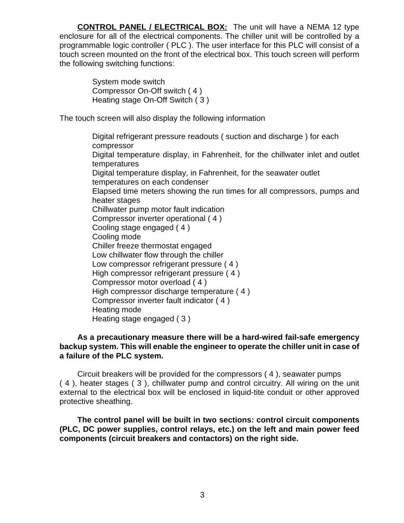
CONTROL PANEL / ELECTRICAL BOX: The unit will have a NEMA 12 typeenclosure for all of the electrical components. The chiller unit will be controlled by aprogrammable logic controller ( PLC ). The user interface for this PLC will consist of atouch screen mounted on the front of the electrical box. This touch screen will performthe following switching functions:
System mode switchCompressor On-Off switch ( 4 )Heating stage On-Off Switch ( 3 )
The touch screen will also display the following information
Digital refrigerant pressure readouts ( suction and discharge ) for each compressor
Digital temperature display, in Fahrenheit, for the chillwater inlet and outlettemperatures
Digital temperature display, in Fahrenheit, for the seawater outlet temperatures on each condenserElapsed time meters showing the run times for all compressors, pumps andheater stagesChillwater pump motor fault indicationCompressor inverter operational ( 4 )Cooling stage engaged ( 4 )Cooling modeChiller freeze thermostat engagedLow chillwater flow through the chiller Low compressor refrigerant pressure ( 4 )High compressor refrigerant pressure ( 4 )Compressor motor overload ( 4 )High compressor discharge temperature ( 4 )Compressor inverter fault indicator ( 4 )Heating modeHeating stage engaged ( 3 )
As a precautionary measure there will be a hard-wired fail-safe emergencybackup system. This will enable the engineer to operate the chiller unit in case ofa failure of the PLC system.
Circuit breakers will be provided for the compressors ( 4 ), seawater pumps ( 4 ), heater stages ( 3 ), chillwater pump and control circuitry. All wiring on the unitexternal to the electrical box will be enclosed in liquid-tite conduit or other approvedprotective sheathing.
The control panel will be built in two sections: control circuit components(PLC, DC power supplies, control relays, etc.) on the left and main power feedcomponents (circuit breakers and contactors) on the right side.
4
AQUA-AIR MANUFACTURING, division of the James D. Nall Co., Inc.1050 East 9th Street, Hialeah, Florida 33010 U.S.A.
Ph. 305-884-8363 Fax 305-883-8549 E-mail [email protected]
The control panel will have quick-connect electrical connectors for all controlcircuit items external to the control panel. This will eliminate any wiring problemsduring the assembly phase at the shipyard and also significantly decrease theoverall number of labor hours necessary to install the unit. All main power feedsfor compressors, pumps and heaters will still need to be hardwired.
FRAME: The frame for the unit will be constructed of appropriately sized steelchannel, square tube and angle. All welds will be by MIG welding procedure. Completedframe will be primed with a red lead based primer and then painted to meet 500 hour saltspray requirement. Color will be the standard Aqua-Air white enamel finish. Stainlesssteel drain pans with a non-corrosive internal coating will be installed under anycondensate producing components. The compressors will be enclosed in an aluminumsound shield to reduce the noise from the compressors. The frame will be built in sucha way as to allow it to be disassembled and carried into the vessel through thestandard ship’s doorways.
i:\wordpfct\aq900hdr2008c.wpd


M/Y “Gallant Lady”DeVries 651
OM75P-4VIHDChiller RetrofitTouchscreen
INSTALLATION OPERATION
MAINTENANCE


1
CHILLER UNIT SPECIFICATION
OM72P-2VEKCOOLING CAPACITY: 72 tons ( 864,000 BTU/H ) { 253 kW } at 45/ F { 7.2/ C } leaving watertemperature and 55/ F { 12.8/ C } returning water temperature. Chiller unit flow rate will beapproximately 216 gpm { 49 m3h }. Condenser flow rate ( each ) is to be approximately 144gpm { 33 m3h } entering at a maximum temperature of 90/ F { 32/ C }. All ratings are at afouling factor of 0.0005
CONSTRUCTION & RATINGS: The chiller unit shall be constructed in accordance with ARIStandard 590-86 and shall comply with all applicable NEC and ASME codes for water cooledchillers.
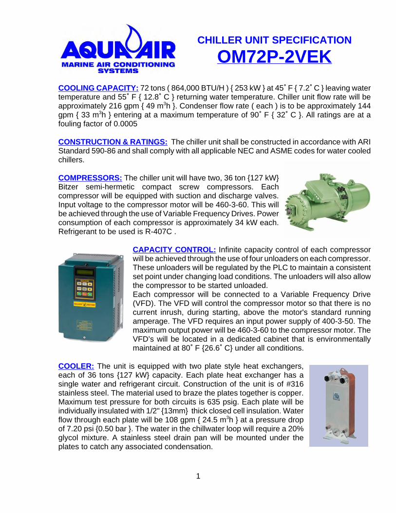
COMPRESSORS: The chiller unit will have two, 36 ton {127 kW}Bitzer semi-hermetic compact screw compressors. Eachcompressor will be equipped with suction and discharge valves.Input voltage to the compressor motor will be 460-3-60. This willbe achieved through the use of Variable Frequency Drives. Powerconsumption of each compressor is approximately 34 kW each.Refrigerant to be used is R-407C .
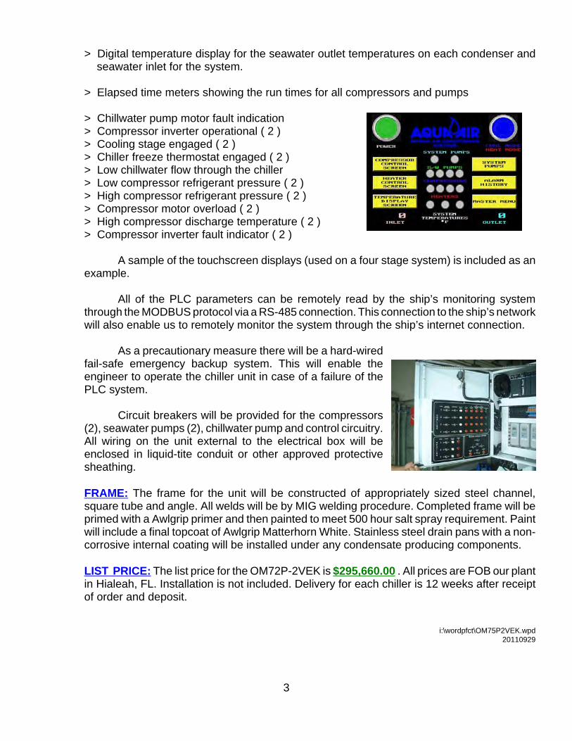
CAPACITY CONTROL: Infinite capacity control of each compressorwill be achieved through the use of four unloaders on each compressor.These unloaders will be regulated by the PLC to maintain a consistentset point under changing load conditions. The unloaders will also allowthe compressor to be started unloaded.Each compressor will be connected to a Variable Frequency Drive(VFD). The VFD will control the compressor motor so that there is nocurrent inrush, during starting, above the motor's standard runningamperage. The VFD requires an input power supply of 400-3-50. Themaximum output power will be 460-3-60 to the compressor motor. TheVFD’s will be located in a dedicated cabinet that is environmentallymaintained at 80/ F {26.6/ C} under all conditions.
COOLER: The unit is equipped with two plate style heat exchangers,each of 36 tons {127 kW} capacity. Each plate heat exchanger has asingle water and refrigerant circuit. Construction of the unit is of #316stainless steel. The material used to braze the plates together is copper.Maximum test pressure for both circuits is 635 psig. Each plate will beindividually insulated with 1/2" {13mm} thick closed cell insulation. Waterflow through each plate will be 108 gpm { 24.5 m3h } at a pressure dropof 7.20 psi {0.50 bar }. The water in the chillwater loop will require a 20%glycol mixture. A stainless steel drain pan will be mounted under theplates to catch any associated condensation.

2
CONDENSER: The unit is equipped with two shell and tube marine condensers. The shell isconstructed of ASME spec SA-53 steel pipe. Shells are shot blasted and cleaned beforeassembly. Tubes are high performance enhanced surface seamless 90/10 Cupro-Nickel tubesto ASME spec SB-359. Tubes are roller expanded into double grooved tubesheets to assuretight joints. Tubesheets are 90/10 Cupro-Nickel to ASME spec SB-171 Alloy 706. Tubesupports are quality steel plug welded to the shell.Heads are cast bronze with integral pass partitions,ASME spec SB-62. Gaskets are die-cut providingeffective sealing between tubesheets and machinedheads. The refrigerant side is constructed and tested inaccordance with Section VIII, Division 1 of ASME Codefor unfired pressure vessels. Shell side design pressure( refrigerant side ) is 350 psig at 250/ F. Tube side ( water side ) is 150 psig at 150/ F. Everycondenser is tested per ASME Code prior to shipment. Seawater connections are 2-1/2" NPT.Water flow to the condenser will be regulated by using VFD’s to modulate the speed of theseawater pumps based upon the individual compressor discharge pressure. This provides forless system erosion and better discharge pressure control. It also eliminates the large brasswater regulating valves that are inherently problematic in the seawater circuit. A pressure reliefvalve ( set for 350 psig ) on the shell is standard.
REFRIGERANT CIRCUIT: Each of the two refrigerant circuits shall includea liquid line ball valve, replaceable core liquid line filter drier with access fittingfor refrigerant charging, combination moisture indicator and sight glass,refrigerant pressure transducers and thermal expansion valve. All suctionlines will be covered with a minimum of 1/2" closed cell insulation. Allrefrigerant pressure transducers, switches and controls will be installed withisolation valves. The system will utilize Electronic Expansion Valves forprecise refrigerant metering to the evaporators under all conditions.
CONTROL PANEL / ELECTRICAL BOX: The unit will have a NEMA12 type enclosure for all of the electrical components. The chiller unitwill be controlled by a Programmable Logic Controller ( PLC ). Theuser interface for this PLC will consist of a touchscreen mounted onthe front of the electrical box. This touchscreen will perform thefollowing main switching functions in addition to numerous other minorcontrols:
System On-Off SwitchCompressor On-Off Switch ( 2 )Chillwater Pump Selector Switch (Primary/Secondary)
The touch screen will also display the following information
> Digital refrigerant pressure readouts ( suction and discharge ) for each compressor> Digital temperature display for the chillwater inlet and outlet temperatures
3
> Digital temperature display for the seawater outlet temperatures on each condenser and seawater inlet for the system.
> Elapsed time meters showing the run times for all compressors and pumps
> Chillwater pump motor fault indication> Compressor inverter operational ( 2 )> Cooling stage engaged ( 2 )> Chiller freeze thermostat engaged ( 2 )> Low chillwater flow through the chiller > Low compressor refrigerant pressure ( 2 )> High compressor refrigerant pressure ( 2 )> Compressor motor overload ( 2 )> High compressor discharge temperature ( 2 )> Compressor inverter fault indicator ( 2 )
A sample of the touchscreen displays (used on a four stage system) is included as anexample.
All of the PLC parameters can be remotely read by the ship’s monitoring systemthrough the MODBUS protocol via a RS-485 connection. This connection to the ship’s networkwill also enable us to remotely monitor the system through the ship’s internet connection.
As a precautionary measure there will be a hard-wiredfail-safe emergency backup system. This will enable theengineer to operate the chiller unit in case of a failure of thePLC system.
Circuit breakers will be provided for the compressors(2), seawater pumps (2), chillwater pump and control circuitry.All wiring on the unit external to the electrical box will beenclosed in liquid-tite conduit or other approved protectivesheathing.
FRAME: The frame for the unit will be constructed of appropriately sized steel channel,square tube and angle. All welds will be by MIG welding procedure. Completed frame will beprimed with a Awlgrip primer and then painted to meet 500 hour salt spray requirement. Paintwill include a final topcoat of Awlgrip Matterhorn White. Stainless steel drain pans with a non-corrosive internal coating will be installed under any condensate producing components.
LIST PRICE: The list price for the OM72P-2VEK is $295,660.00 . All prices are FOB our plantin Hialeah, FL. Installation is not included. Delivery for each chiller is 12 weeks after receiptof order and deposit.
i:\wordpfct\OM75P2VEK.wpd20110929


James D. Nall Company Inc.
COMPANY HISTORY
Formed in 1941, the James D. Nall Company, Inc. is the oldest name in marine air conditioning with a 66 year history of providing marine air conditioning products and services. It is also the 2nd largest manufacturer of marine air conditioning systems in North America. The company has distributed and installed innovative Direct Expansion (DX) systems of its own design and manufacture since its inception. In 1973 under the trade name of Aqua-Air, the company designed and introduced chillwater technology to the yachting community. The chillwater product designed and manufactured by Aqua-Air, along with direct expansion products supplied by Cruisair were distributed by the company until 1983 when the Cruisair product was replaced with a full line of newly designed, Aqua-Air brand direct expansion products. Since that time, the most diverse and complete lines of direct expansion and chillwater marine air conditioning products, designed for the yacht builders and servicing dealers, have been manufactured and distributed by Aqua-Air.
Quality and innovation have been the hallmark of the company making the Aqua-
Air brand the preferred product throughout the mega yacht segment of the market. Aqua-Air boasts a larger installed base of product on the world’s mega yachts than the sum total of all the other brands combined. Some of the technologies that are commonplace throughout the industry were the Aqua-Air innovations that moved the company and the industry forward. The Fresh Air Make Up System, Digital Thermostat, Racked System, Automatic Compressor Rotation, PLC Control and the use of Variable Frequency Drives were just a few of the past technological advancements fostered by Aqua-Air. Continuing R&D has yielded recent innovations; the new R-407C refrigerant products to take the industry into compliance under the strict environmental protections of the Montreal Protocol, and the “World’s Smallest” self contained system.
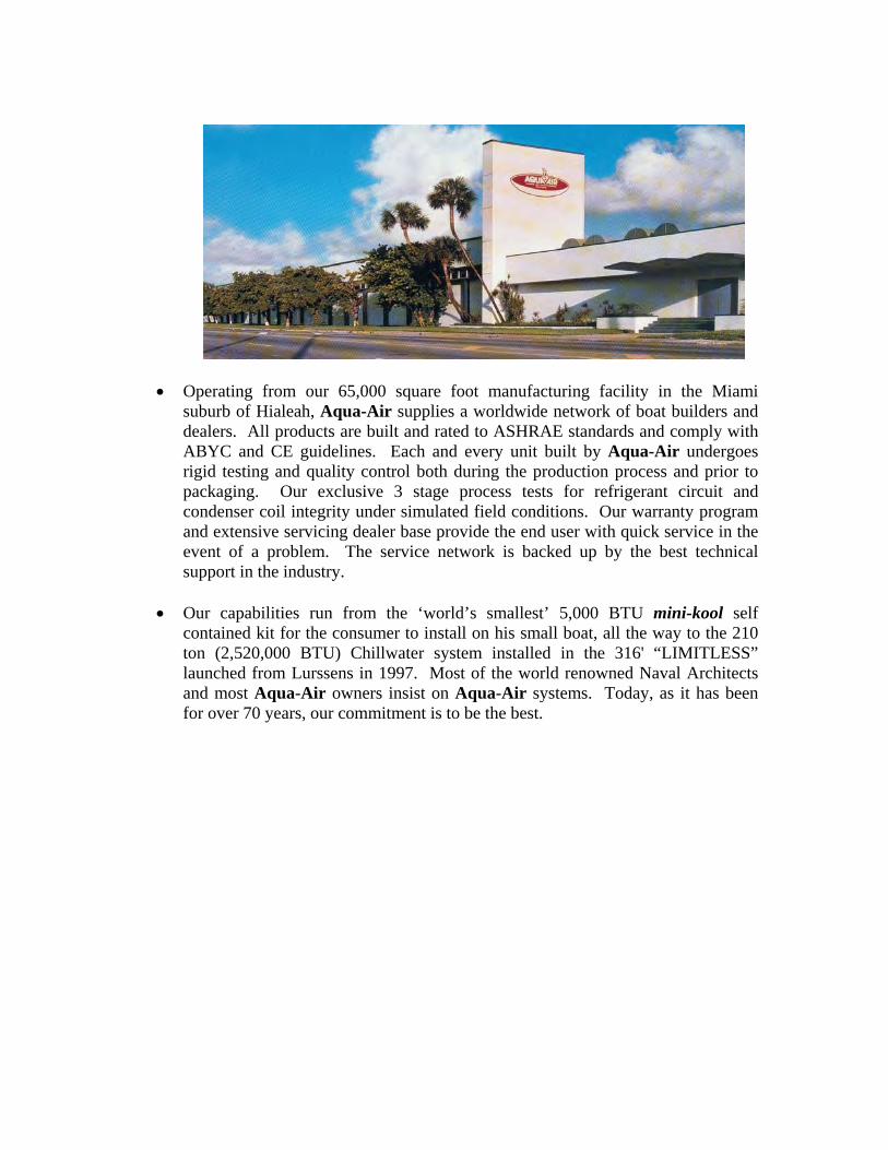
Operating from our 65,000 square foot manufacturing facility in the Miami suburb of Hialeah, Aqua-Air supplies a worldwide network of boat builders and dealers. All products are built and rated to ASHRAE standards and comply with ABYC and CE guidelines. Each and every unit built by Aqua-Air undergoes rigid testing and quality control both during the production process and prior to packaging. Our exclusive 3 stage process tests for refrigerant circuit and condenser coil integrity under simulated field conditions. Our warranty program and extensive servicing dealer base provide the end user with quick service in the event of a problem. The service network is backed up by the best technical support in the industry.
Our capabilities run from the ‘world’s smallest’ 5,000 BTU mini-kool self
contained kit for the consumer to install on his small boat, all the way to the 210 ton (2,520,000 BTU) Chillwater system installed in the 316' “LIMITLESS” launched from Lurssens in 1997. Most of the world renowned Naval Architects and most Aqua-Air owners insist on Aqua-Air systems. Today, as it has been for over 70 years, our commitment is to be the best.

PRODUCT LINE
Chilled Water Systems – Our Alpha Chiller is the largest selling chiller in the megayacht industry today. Ranging in size from 2 ton to 6 ton, and featuring a stainless steel chassis, scroll compressors and AWLGRIP coatings. Compared to other brands, the Alpha Chiller is 22% lighter and 38% smaller in volume. If a vessel’s requirements exceed 6 ton, multiple Alpha Chillers are racked together, manifolded on the seawater and chillwater circuits to form capacities up to 30 ton. Units are available with reverse cycle or cooling only, up to six stages and variable frequency drives to provide surgeless compressor startup. The units are protected with chillwater flow switch and freeze stats on each chiller module, along with a variety of other features. This proven product is simply the best on the market today. In addition, we have the technical expertise and experience, to design and produce large (up to 300 ton) custom chillers incorporating the proven engineering concepts of the Alpha Chiller line, and refined over the years.
Split Systems – We offer a complete line of split DX systems, in capacities of 5,000 to 60,000 BTU. Each of the units is equipped with reverse cycle heat and piston or scroll compressors. Along with the condensing units we also offer a matching line of DX fan coils in a wide array of sizes and configurations insuring that every boat owner has versatility of installation.
Self Contained Systems – For the smaller boats, we have a complete line of self-contained units, including the smallest unit on the market, the Aqua-Air Minikool. The product line includes capacities from 5,000 to 24,000 BTU, and the compact size, quiet operation and efficient design lends itself to installation under a berth, in a closet or any other underutilized area. All units with the exception of the Minikool come standard with reverse cycle heat.
Accessories – This is a supporting product line that includes all the miscellaneous components that are available for use with our core products, such as ducting, grilles, pumps, thermostats and controls, relays, transition boxes, filters, line sets and various installation kits.
PRODUCT DOCUMENTATION
Bills of Material – All models have been computerized and an updated bill of material is available on demand from the computer network.
Drawings and Specifications – Although some of the older drawings are still in hard copy format, all of the newer drawings (after 1994) are CAD generated.
History (manuals) – The Company has maintained over the years, an installation/ operation manual on each yacht that carries our chillwater equipment. This manual includes an equipment list, wiring diagrams and product specification sheets on all products and accessories supplied to that particular vessel. All new manuals are being generated and stored electronically.
TERMS
Terms for international orders are 50% with the order and the remainder before shipment (generally wire transfer).
Self Contained & DX systems – Small orders (less than $5K) normally do not require a deposit, but payment in full is required before shipment.
WEBSITE
The company website was designed in house and can be accessed at www.aquaair.com

James D. Nall Co., Inc.Aqua-Air Manufacturing
Limited Warranty
I. GENERALLY
A. This limited Warranty applies to any products manufactured by the James D. Nall Co., Inc., hereinsometimes referred to as “COMPANY,” “MANUFACTURER” or “AQUA-AIR.” The Company furnishes thiswritten notice that its products and systems are under a limited warranty to be free from design andmanufacturing defects in material and workmanship under normal use and service or as otherwiseauthorized by the Manufacturer. The obligation of the Company is limited to replacing or repairing anycomponent which will disclose defects within the time frames defined in section II (Warranty Period) andwhich, upon examination, may appear to the satisfaction of the Company to be defective or not as specifiedfor its performance. Within thirty (30) days of the discovery a claim must be filed with the Company andthe faulty component must be returned, transportation prepaid, to the Company. At the specific option ofthe Company it may, as an alternative to the return of the component, examine and inspect it in place atits usual location. Nothing herein contained will create any obligation of the Company to so examine orinspect the component away from the premises of the Manufacturer.
B. This Warranty will not apply to:1. Failures resulting from abuse, fire or submergence.2. Any part manufactured by the Company which will have been altered so as to impair original
characteristics.3. Any parts which fail as a result of misuse, improper application or improper installation.4. Items not manufactured by the company, i.e., items which are purchased from another
manufacturer and supplied as received by the Company without alteration or modification. TheCompany will disclose the existence of any warranty, limited or otherwise, if any, given by themanufacturer of any items not made by Aqua-Air.
5. Components or parts used by or applied by the purchaser as an integral part of products notmanufactured by the Company.
6. The failure of the buyer to give the required notice or to comply with other conditions of this limitedwarranty.
C. This limited warranty is made in lieu of all other express warranties, obligations or liabilities on the part ofAqua-Air. In addition, Aqua-Air disclaims, without limitation, any liabilities arising from incidental orconsequential damages except as may occur while the product is being operated by and under the controlof the Company. In such instances where a cash refund is made, the refund will effect the cancellation ofthe contract of sale with no subsequent reservations of rights being retained by the purchaser. The termsand conditions of this limited warranty will be governed by the laws of the State of Florida.
D. No dealer is the agent for Aqua-Air except for the purpose of administering this limited warranty to theextent herein provided. Aqua-Air does not authorize any dealer or other person to assume for Aqua-Air anyliability in connection with this limited warranty or any liability or expense incurred in the replacement orrepair of its products other than those expressly authorized herein.
E. The Company reserves the right to improve its products through changes in design or material withoutbeing obligated to incorporate such changes in products of prior manufacture and to make changes at anytime in design, materials or part of units of any one year model, without obligation or liability to owners ofunits of the same year’s model of prior manufacture.
F. This warranty gives you, the purchaser, specific legal rights. You also have implied warranty rights,including an implied warranty of merchantability, which means that your product must be fit for the ordinarypurpose for which such goods are used. The duration of this implied warranty is limited to the duration ofthe expressed warranty as found in section II, WARRANTY PERIOD.
G. This warranty extends only to the original purchaser (other than for purposes of resale) of Aqua-Airwarranty equipment and any other such person who is entitled, under applicable State law, to enforceagainst the warrantor the obligations of the warranty.

II. WARRANTY PERIOD
A. The limited warranty covers the following periods (whichever comes first):
1. Twelve (12) months from the date that the selling dealer puts the system into operation or
2. Eighteen (18) months from the date that the system is sold to the original purchaser.
In the case of factory installed equipment, the warranty period begins when the selling dealer first puts theequipment into operation. The warranty beginning date may be prior to the date of delivery to the retailpurchaser. No warranty claim can be honored unless the owners’ registration form is on file with theCompany. This form, which is enclosed, should therefore be returned to Aqua-Air immediately uponpurchase of items covered by this warranty.
B. All Aqua-Air components have a name plate on which there is a model and serial number. The serialnumber is date coded, indicating when the unit was originally sold.
C. To determine whether or not any Aqua-Air component is in warranty you may contact Aqua-Air at:
Aqua-Air Manufacturing, division of the James D. Nall Co., Inc1050 E. 9th St., Hialeah, FL 33010Phone: 305-884-8363 Fax: 305-883-8549 Email: [email protected]
III. WARRANTY COVERAGE
The Aqua-Air warranty covers the basic component units manufactured by Aqua-Air. Installation and applicationof Aqua-Air components are not warranted by Aqua-Air because Aqua-Air has no control or authority over theselection, location, application or installation of these components. The following are installation or applicationconsiderations not covered by the Aqua-Air warranty:
1. Flare or solder joint leaks in the connecting copper tubing.2. Condensate leakage resulting from the inadequately insulated connecting tubing or improperly installed
condensate drains.3. Water flow problems resulting from the improper plumbing considerations or inadequate filters or strainers.4. Low voltage or loss of power as a result of inadequate wiring, circuit breakers, fuses or wire connectors.5. Low capacity output resulting from improperly sized or located air grilles, vents, ducts, plenums or cooling
units.6. Inadequate cooling or heating capacity resulting from the selection of undersized equipment. Aqua-Air may
make recommendations as to the capacity of the equipment for a specific installation, however, the finaldecision concerning exactly what equipment will be used and the responsibility for the effectiveness of theequipment selected lies solely with the purchaser. The only exception and only case in which Aqua-Airwould assume full responsibilities would be in the event Aqua-Air were retained under a separate contractto make such determinations.
7. Inadequate cooling or heating resulting from systems being improperly charged with refrigerant gas.8. Pump seal leakage due to the pumps being run with insufficient water in the head.
IV. LIMITED WARRANTY ALLOWANCES
Limited warranty allowances as outlined in publications F-104 and F-110 are also available to defer expensesincurred in the repair or replacement of all such components for the period of the system warranty. Replacementparts and components for out-of-warranty systems are also warranted for one year but no allowance to deferexpenses incurred in the repair or replacement of such components is available. Components or parts not usedas an integral part of an Aqua-Air system are not covered by the Company warranty.
I:\wordpfct\82010-LimitedWarranty.wpd
100 TonChillers

1
CHILLER UNIT SPECIFICATION
OM100-4E
COOLING CAPACITY: 100 tons [ 1,200,000 BTU/H ] [ 300,000 KCAL/H ] at
40/ F ( 7.2/ C ) leaving water temperature and 50/ F ( 12.8/ C ) returning water
temperature. Chiller unit flow rate will be approximately 300 gpm. Condenser flow
rate ( each ) is to be approximately 100 gpm entering at a maximum temperature of 90/ F
( 32/ C ). All ratings are at a fouling factor of 0.0005 .
CONSTRUCTION & RATINGS: The chiller unit shall be constructed in accordance with
ARI Standard 590-86 and shall comply with all applicable NEC and ASME codes for water
cooled chillers.
COMPRESSORS: The chiller unit will have four, 25 ton Bitzer semi-hermetic reciprocating
compressors. Each compressor will be equipped with suction and discharge valves. Input
voltage to the compressor motor will be 460-3-60. Power consumption of each compressor
is approximately 21.1 kW each. Refrigerant to be used is R-22
CHILLER BARREL: The unit is equipped with a four circuit, 100 ton shell and tube chiller
barrel. The shell is constructed of steel per ASME specification SA-53, Grade B. The shells
are shot blasted and cleaned before assembly. The tubes are high performance seamless
copper tube to ASME specs. Tubes are roller expanded into double grooved tube sheets.
The tube sheets are ASME grade carbon steel. The baffles are hot rolled steel, terne plated
for added corrosion resistance. The heads are ASME grade steel fabricated ring and cover
type steel heads. Gaskets are die-cut medium density elastomer in conformance with
relevant specifications. The chillwater connections are 5" 150lb ANSI raised face flanges
(2). The refrigerant side is constructed in accordance with the latest edition of Section VIII,
Division I of ASME Code for pressure vessels and stamped accordingly. Tube side
(refrigerant side) design pressure is 200 PSIG at 100 /F. Shell side (fluid side) design
pressure is 150 PSIG at 120 /F. The entire shell is covered with 3/4" (19mm) thick Armaflex
foam rubber insulation.

2
CONDENSERS: The unit is equipped with four 25 ton shell and tube marine condensers.
The shell is constructed of ASME spec SA-53 steel pipe. Shells are shot blasted and
cleaned before assembly. Tubes are high performance enhanced surface seamless 90/10
Cupro-Nickel tubes to ASME spec SB-359. Tubes are roller expanded into double grooved
tubesheets to assure tight joints. Tubesheets are 90/10 Cupro-Nickel to ASME spec SB-171
Alloy 706. Tube supports are quality steel plug welded to the shell. Heads are cast bronze
with integral pass partitions, ASME spec SB-62. Gaskets are die-cut providing effective
sealing between tubesheets and machined heads. The refrigerant side is constructed and
tested in accordance with Section VIII, Division 1 of ASME Code for unfired pressure
vessels. Shell side design pressure ( refrigerant side ) is 350 psig at 250/ F. Tube side (
water side ) is 150 psig at 150/ F. Every condenser is tested per ASME Code prior to
shipment. Seawater connections are 2" FPT.
Water flow to the condenser will be regulated by a discharge pressure actuated water
regulating valve. A pressure relief valve ( set for 350 psig ) on the shell is standard.
REFRIGERANT CIRCUIT: Each of the four refrigerant circuits shall include a liquid
line ball valve, replaceable core liquid line filter drier with access fitting for refrigerant
charging and refrigerant isolation valves, combination moisture indicator and sight glass,
liquid line solenoid and thermal expansion valve. All suction lines will be covered with a
minimum of 1/2" closed cell insulation.
CONTROL PANEL / ELECTRICAL BOX: The unit will have a single NEMA 12 type
electrical box. The panel will be comprised of the following main components:
< Main Control:Hydro-Matic microprocessor based control system with the following
primary features:
< On-Off control of chiller compressors
< Display of chillwater inlet and outlet temperatures for the entire unit
< Display of seawater outlet temperatures for each fifteen ton module
< Monitors refrigerant high and low pressure faults, freeze thermostats and flow switch
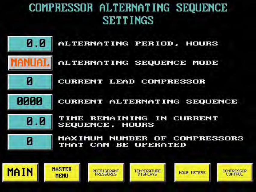
< Automatic sequencing of compressors to achieve equal run times
< Service LED indicates fault condition
< Temperatures can be displayed in either Fahrenheit or Celsius
< Compressor LED's indicate operating status of each compressor

3
CONTROL PANEL / ELECTRICAL BOX (cont)
< Incoming power is checked for low and high voltage conditions
Motor starters will be provided for the compressors, chillwater and seawater pumps (2). A
selector switch will be provided on the front of the panel to select between the primary and standby
seawater pumps.
Circuit breakers will be provided for each compressor ( 5 ), seawater pump, chillwater pump
and control circuitry. Circuit breakers will be rated for use on 480/3/60 power input.
FRAME: The frame for the unit will be constructed of appropriately sized steel channel,
square tube and angle. All welds will be by MIG welding procedure. Completed frame will
be primed and then painted to meet 500 hour salt spray requirement using Awlgrip
Matterhorn White paint. Stainless steel drain pans with a non-corrosive internal coating
will be installed under any condensate producing components.
i:\wordpfct\om1004e.wpd


1
CHILLER UNIT SPECIFICATION
OM100-4VIHE
COOLING CAPACITY: 100 tons [ 1,200,000 BTU/H ] [ 300,000 KCAL/H ] at
40/ F ( 7.2/ C ) leaving water temperature and 50/ F ( 12.8/ C ) returning water
temperature. Chiller unit flow rate will be approximately 300 gpm. Condenser flow
rate ( each ) is to be approximately 100 gpm entering at a maximum temperature of
90/ F ( 32/ C ). All ratings are at a fouling factor of 0.0005 .
HEATING CAPACITY: 108 kW [ 368,511 BTU/H ] [ 92,863 KCAL/H ] of total
heating capacity at 140/ F ( 60/ C ) leaving water temperature and 120/ F
( 48.8/ C ) returning water temperature.
CONSTRUCTION & RATINGS: The chiller unit shall be constructed in
accordance with ARI Standard 590-86 and shall comply with all applicable NEC and
ASME codes for water cooled chillers.
COMPRESSORS: The chiller unit will have four, 25 ton Bitzer semi-hermetic
reciprocating compressors. Each compressor will be equipped with suction and
discharge valves. Input voltage to the compressor motor will be 460-3-60. Power
consumption of each compressor is approximately 21.1 kW each. Refrigerant to be
used is R-407C .

2
CAPACITY CONTROL: Chiller unit capacity control will be achieved through
the use of three variable frequency drive ( VFD ) units, one for each compressor.
The VFD will vary the compressor motor speed from a maximum of 100% of
capacity to a minimum of 70%. The VFD requires an input power supply of 460-3-
60. The maximum output power will be 460-3-60 to the compressor motor. The VFD
output will be regulated via the RS-485 network between the VFD and the chiller unit
PLC. The VFD voltage/frequency output will be varied based upon chilled water
outlet temperature. The VFD will also control the compressor motor so that there is
no current inrush, during starting, above the motor's standard running amperage.
CHILLER BARREL: The unit is equipped with a four circuit, 100 ton shell and
tube chiller barrel. The shell is constructed of steel per ASME specification SA-53,
Grade B. The shells are shot blasted and cleaned before assembly. The tubes are
high performance seamless copper tube to ASME specs. Tubes are roller expanded
into double grooved tube sheets. The tube sheets are ASME grade carbon steel.
The baffles are hot rolled steel, terne plated for added corrosion resistance. The
heads are ASME grade steel fabricated ring and cover type steel heads. Gaskets
are die-cut medium density elastomer in conformance with relevant specifications.
The chillwater connections are 5" 150lb ANSI raised face flanges (2). The refrigerant
side is constructed in accordance with the latest edition of Section VIII, Division I of
ASME Code for pressure vessels and stamped accordingly. Tube side (refrigerant
side) design pressure is 200 PSIG at 100 /F. Shell side (fluid side) design pressure
is 150 PSIG at 120 /F. The entire shell is covered with 3/4" (19mm) thick Armaflex
foam rubber insulation.
3
CONDENSERS: The unit is equipped with four 25 ton shell and tube marine
condensers. The shell is constructed of ASME spec SA-53 steel pipe. Shells are
shot blasted and cleaned before assembly. Tubes are high performance enhanced
surface seamless 90/10 Cupro-Nickel tubes to ASME spec SB-359. Tubes are roller
expanded into double grooved tubesheets to assure tight joints. Tubesheets are
90/10 Cupro-Nickel to ASME spec SB-171 Alloy 706. Tube supports are quality steel
plug welded to the shell. Heads are cast bronze with integral pass partitions, ASME
spec SB-62. Gaskets are die-cut providing effective sealing between tubesheets and
machined heads. The refrigerant side is constructed and tested in accordance with
Section VIII, Division 1 of ASME Code for unfired pressure vessels. Shell side
design pressure ( refrigerant side ) is 350 psig at 250/ F. Tube side ( water side ) is
150 psig at 150/ F. Every condenser is tested per ASME Code prior to shipment.
Seawater connections are 2" FPT.
Water flow to the condenser will be regulated by a discharge pressure actuated
water regulating valve. A pressure relief valve ( set for 350 psig ) on the shell is
standard.
IMMERSION HEATER ELEMENTS: The unit is equipped with a three stage,
12 element, 108 kW immersion heating tank assembly. The heater elements are
rated at full wattage on 460-3-60 power input. The elements are constructed of
Incoloy with a maximum watt density of 100 watts per square inch. The element
heater tank will be constructed of plate steel to ASME specifications. All welds will
be by MIG welding procedure. The tank design rating pressure is 150 psig at 200/
Fahrenheit. The tank will be equipped with a ASME water pressure relief valve.
REFRIGERANT CIRCUIT: Each of the four refrigerant circuits shall include
a liquid line ball valve, replaceable core liquid line filter drier with access fitting for
refrigerant charging and refrigerant isolation valves, combination moisture indicator
and sight glass, liquid line solenoid and thermal expansion valve. All suction lines
will be covered with a minimum of 1/2" closed cell insulation.

4
CONTROL PANEL / ELECTRICAL BOX: The unit will have a NEMA 12 type
enclosure for all of the electrical components. The chiller unit will be controlled by
a programmable logic controller ( PLC ). The user interface for this PLC will consist
of a touch screen mounted on the front of the electrical box. This touch screen will
perform the following switching functions:
System mode switch
Compressor On-Off switch ( 4 )
Heating stage On-Off Switch ( 3 )
The touch screen will also display the following information
Digital refrigerant pressure readouts ( suction and discharge ) for each
compressor
Digital temperature display, in Fahrenheit, for the chillwater inlet and outlet
temperatures
Elapsed time meters showing the run times for all compressors, pumps
and heater stages
Chillwater pump motor fault indication
Compressor inverter operational ( 4 )
Cooling stage engaged ( 4 )
Cooling mode
Chiller freeze thermostat engaged
Low chillwater flow through the chiller
Low compressor refrigerant pressure ( 4 )
High compressor refrigerant pressure ( 4 )
Compressor motor overload ( 4 )
High compressor discharge temperature ( 4 )
Compressor inverter fault indicator ( 4 )
5
AQUA-AIR MANUFACTURING, division of the James D. Nall Co., Inc.1050 East 9th Street, Hialeah, Florida 33010 U.S.A.
Ph. 305-884-8363 Fax 305-883-8549 E-mail [email protected]
Heating mode
Heating stage engaged ( 3 )
A complete description of the functions of the PLC / Touchscreen system can
be found in the document following this specification.
A phone communication modem will be included that will allow the PLC to be
accessed remotely for diagnostic purposes.
An Ethernet card will allow communication (via MODBUS) between the chiller
and the five air handler control panels as well as with the ships’ monitoring system.
Circuit breakers will be provided for the compressors ( 4 ), seawater pumps
( 4 ), heater stages ( 3 ), chillwater pump and control circuitry. All wiring on the unit
external to the electrical box will be enclosed in liquid-tite conduit or other approved
protective sheathing.
FRAME: The frame for the unit will be constructed of appropriately sized steel
channel, square tube and angle. All welds will be by MIG welding procedure.
Completed frame will be primed and then painted to meet 500 hour salt spray
requirement using Awlgrip Matterhorn White paint. Stainless steel drain pans with
a non-corrosive internal coating will be installed under any condensate producing
components.
i:\wordpfct\om100-4vihe.wpd


170 TonChillers

1
CHILLER UNIT SPECIFICATION
OM170P-2VEK
COOLING CAPACITY: 170 tons ( 2,040,000 BTU/H ) { 600 kW } at 35° F { 2° C }leaving water temperature and 45° F { 7° C } returning water temperature. Chiller unit flow ratewill be approximately 418 gpm { 95 m3h }. Condenser flow rate ( each ) is to be approximately340 gpm { 77 m3h } entering at a maximum temperature of 90° F { 32° C }. All ratings are ata fouling factor of 0.0005
CONSTRUCTION & RATINGS: The chiller unit shall be constructed in accordancewith ARI Standard 590-86 and shall comply with all applicable NEC and ASME codes forwater cooled chillers.
COMPRESSORS: The chiller unit will have two, 85 ton {300kW} Bitzer semi-hermetic compact screw compressors. Eachcompressor will be equipped with suction and discharge valves. Inputvoltage to the compressor motor will be 380-3-50. Power consumptionof each compressor is approximately 91 kW each. Refrigerant to beused is R-407C .
CAPACITY CONTROL: Infinite capacity control of each compressor will be achievedthrough the use of four unloaders on each compressor. These unloaders will be regulated bythe PLC to maintain a consistent set point under changing load conditions. The unloaders willalso allow the compressor to be started unloaded.Each compressor will be connected to a Variable Frequency Drive ( VFD ). The VFD willcontrol the compressor motor so that there is no current inrush, during starting, above themotor's standard running amperage. The VFD requires an input power supply of 380-3-50.The maximum output power will be 380-3-50 to the compressor motor.
COOLER: The unit is equipped with two plate style heatexchangers, each of 85 tons capacity. Each plate heat exchanger hasa single water and refrigerant circuit. Construction of the unit is of #316stainless steel. The material used to braze the plates together iscopper. Maximum test pressure for both circuits is 635 psig. Each platewill be individually insulated with 1/2" {13mm} thick closed cellinsulation. Water flow through each plate will be 209 gpm { 47.5 m3h }at a pressure drop of 7.20 psi {0.50 bar }. The water in the chillwaterlook will require a 10% glycol mixture. Dowtherm SR-1 isrecommended.
2
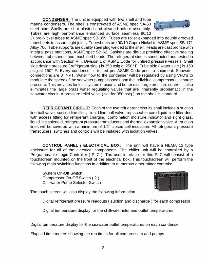
CONDENSER: The unit is equipped with two shell and tubemarine condensers. The shell is constructed of ASME spec SA-53steel pipe. Shells are shot blasted and cleaned before assembly.Tubes are high performance enhanced surface seamless 90/10Cupro-Nickel tubes to ASME spec SB-359. Tubes are roller expanded into double groovedtubesheets to assure tight joints. Tubesheets are 90/10 Cupro-Nickel to ASME spec SB-171Alloy 706. Tube supports are quality steel plug welded to the shell. Heads are cast bronze withintegral pass partitions, ASME spec SB-62. Gaskets are die-cut providing effective sealingbetween tubesheets and machined heads. The refrigerant side is constructed and tested inaccordance with Section VIII, Division 1 of ASME Code for unfired pressure vessels. Shellside design pressure ( refrigerant side ) is 350 psig at 250° F. Tube side ( water side ) is 150psig at 150° F. Every condenser is tested per ASME Code prior to shipment. Seawaterconnections are 3" NPT. Water flow to the condenser will be regulated by using VFD’s tomodulate the speed of the seawater pumps based upon the individual compressor dischargepressure. This provides for less system erosion and better discharge pressure control. It alsoeliminates the large brass water regulating valves that are inherently problematic in theseawater circuit. A pressure relief valve ( set for 350 psig ) on the shell is standard.
REFRIGERANT CIRCUIT: Each of the two refrigerant circuits shall include a suctionline ball valve, suction line filter, liquid line ball valve, replaceable core liquid line filter drierwith access fitting for refrigerant charging, combination moisture indicator and sight glass,liquid line solenoid, refrigerant pressure transducers and thermal expansion valve. All suctionlines will be covered with a minimum of 1/2" closed cell insulation. All refrigerant pressuretransducers, switches and controls will be installed with isolation valves.
CONTROL PANEL / ELECTRICAL BOX: The unit will have a NEMA 12 typeenclosure for all of the electrical components. The chiller unit will be controlled by aProgrammable Logic Controller ( PLC ). The user interface for this PLC will consist of atouchscreen mounted on the front of the electrical box. This touchscreen will perform thefollowing main switching functions in addition to numerous other minor controls:
System On-Off SwitchCompressor On-Off Switch ( 2 )Chillwater Pump Selector Switch
The touch screen will also display the following information
Digital refrigerant pressure readouts ( suction and discharge ) for each compressor
Digital temperature display for the chillwater inlet and outlet temperatures
Digital temperature display for the seawater outlet temperatures on each condenser
Elapsed time meters showing the run times for all compressors and pumps

3
AQUA-AIR MANUFACTURING, division of the James D. Nall Co., Inc.1050 East 9th Street, Hialeah, Florida 33010 U.S.A.
Ph. 305-884-8363 Fax 305-883-8549 E-mail [email protected]
Chillwater pump motor fault indicationCompressor inverter operational ( 2 )Cooling stage engaged ( 2 )Chiller freeze thermostat engagedLow chillwater flow through the chiller Low compressor refrigerant pressure ( 2 )High compressor refrigerant pressure ( 2 )Compressor motor overload ( 2 )High compressor discharge temperature ( 2 )Compressor inverter fault indicator ( 2 )
A sample of the touchscreen displays (used on a four stage system) is included as anexample.
As a precautionary measure there will be a hard-wired fail-safe emergency backupsystem. This will enable the engineer to operate the chiller unit in case of a failure of the PLCsystem.
Circuit breakers will be provided for the compressors ( 2 ), seawater pumps ( 2 ), chillwater pump and control circuitry. All wiring on theunit external to the electrical box will be enclosed in liquid-titeconduit or other approved protective sheathing.
FRAME: The frame for the unit will be constructed ofappropriately sized steel channel, square tube and angle. Allwelds will be by MIG welding procedure. Completed frame willbe primed with a red lead based primer and then painted tomeet 500 hour salt spray requirement. Paint will include a finaltopcoat of Awlgrip Matterhorn White. Stainless steel drainpans with a non-corrosive internal coating will be installedunder any condensate producing components.
NET PRICE: The net price for each OM170P-2VEK is $373,256.00 each. All pricesare FOB our plant in Miami, FL. Delivery for each chiller is 16 weeks after receipt of order anddeposit.
i:\wordpfct\OM170P-2VEK Sterling Yacht Vega 85m.wpd


210 TonChillers