high availability systems selection guide, ia-sg003b...
TRANSCRIPT

High Availability SystemsCompactLogix and ControlLogix Systems
Selection Guide

2 Rockwell Automation Publication IA-SG003B-EN-P - October 2012
High Availability Systems Selection Guide
What’s InsideTopic Page
High Availability Systems 3
Hardware Redundancy 5
Hot Backup 13
High Availability Systems
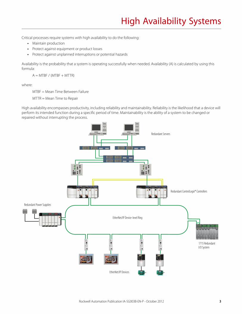
Critical processes require systems with high availability to do the following:• Maintain production• Protect against equipment or product losses• Protect against unplanned interruptions or potential hazards
Availability is the probability that a system is operating successfully when needed. Availability (A) is calculated by using this formula:
A = MTBF / (MTBF + MTTR)
where:
MTBF = Mean Time Between Failure
MTTR = Mean Time to Repair
High availability encompasses productivity, including reliability and maintainability. Reliability is the likelihood that a device will perform its intended function during a specific period of time. Maintainability is the ability of a system to be changed or repaired without interrupting the process.
EtherNet/IP™
EtherNet/IP™
RUN SD OKFORCE
Logix5575
RUN SD OKFORCE
Logix5575 EtherNet/IP™ EtherNet/IP™
RUN SD OKFORCE
Logix5575
RUN SD OKFORCE
Logix5575 EtherNet/IP™
Redundant ControlLogix® Controllers
EtherNet/IP Device-level Ring
Redundant Servers
EtherNet/IP Devices
Redundant Power Supplies
1715 Redundant I/O System
Rockwell Automation Publication IA-SG003B-EN-P - October 2012 3

High Availability Systems
High Availability OptionsCharacteristic Hardware Redundancy Hot Backup
Hardware • ControlLogix controller, redundancy modules, and firmware• Embedded switch technology in EtherNet/IP devices• Redundant ControlNet media and devices• Redundant ControlLogix power supplies
• 1769-L30ER, 1769-L33ER CompactLogix™ controllers• 1756-L7x ControlLogix controllers with 1756-EN2T or
1756-EN2TR EtherNet/IP modules
Programming requirements None • Minimal; code generator tool• Application programming required for switchover of process
Project maintenance One project automatically crossloads from primary to secondary • Two projects, each downloaded to appropriate controller• End user should develop and implement appropriate test plan
Impact on program scan time Can be significant Small
Online program changes Yes, edits automatically sent to secondary Yes, but must edit both programs
I/O forcing Yes, forces automatically sent to secondary Yes, but must force in both controllers
Data synchronization Data is automatically sent to secondary Data must be synchronized via user logicOther systems must complete dual writes to update primary and secondary
Controller failure detection time Immediate Varies with fault type
Switchover time 20 ms, average for 1756-RM2 module 250 ms, minimum
Supported I/O Same as non-redundant ControlLogix controllers • 1756 ControlLogix I/O• 1794 FLEX I/O
Local I/O modules No Not supported
EtherNet/IP I/O modules Yes, multicast only Yes, multicast only
ControlNet I/O modules Yes Yes
DeviceNet I/O modules No No
Motion control No No
HMI communication Yes, system can swap IP addresses during switchover Not automatic
4 Rockwell Automation Publication IA-SG003B-EN-P - October 2012

Hardware Redundancy
The ControlLogix platform offers increased high availability through these features:• Improved diagnostics, including the following:
– Internal diagnostics and status indicators– Diagnostic I/O modules– HART and other device technologies with sensor and actuator diagnostics– Alarms and events – Inherent machine diagnostics
• Runtime modifications, including the following:– Runtime partial import– Online edits– Removal and insertion under power (RIUP) of 1756, 1715, and 1794/1797 modules– Addition of 1756 and 1715 modules in Run mode– Ability to update firmware at runtime
The ControlLogix controller supports the following redundancy hardware:• Redundant controllers and I/O• Resilient EtherNet/IP media• Redundant ControlNet media• Redundant power supplies• Redundant communication adapters in a redundant chassis
Rockwell Automation Publication IA-SG003B-EN-P - October 2012 5

Hardware Redundancy
Redundant Control HardwareThe ControlLogix Enhanced Redundancy System uses a redundant chassis pair with identically specific components in each. One redundancy module and at least one ControlNet or EtherNet/IP communication module are required. The application operates from a primary chassis, but can switch over to the secondary chassis and components if necessary.
RUN SD OKFORCE
Logix5575 EtherNet/IP™ EtherNet/IP™ EtherNet/IP™ EtherNet/IP™ EtherNet/IP™
RUN SD OKFORCE
Logix5575 EtherNet/IP™ EtherNet/IP™ EtherNet/IP™ EtherNet/IP™ EtherNet/IP™
EtherNet/IP™
Redundant Chassis Pair
EtherNet/IP Switch
1756 ControlLogix I/O
Workstation
1715 Redundant I/O PowerFlex® Drive Connected via 1783-ETAP
1734 POINT I/O™
Redundant Crossload Media
6 Rockwell Automation Publication IA-SG003B-EN-P - October 2012

Hardware Redundancy
In a redundant controller system, you need these components:• Two 1756 chassis, each with the same:
– Number of slots– Modules in the same slots– Redundancy firmware revisions in each module– If on a ControlNet network, two additional ControlNet nodes outside the redundant chassis pair
• The same redundancy module (1756-RM2) per chassis, to support the following:– One or two 1756-L71, 1756-L72, 1756-L73, 1756-L74, 1756-L75, 1756-L61, 1756-L62, 1761-L63 controllers or only one
1756-L64, 1756-L65 controller– Maximum of seven communication modules, which can be 1756-CN2/B, 1756-CN2R/B, 1756-EN2T, 1756-EN2TR, and
1756-EN2F modules
For additional redundancy rules and restrictions, see ControlLogix Enhanced Redundancy System User Manual, publication 1756-UM535.
Redundant Controller Operation
The redundant system is a floating master system. Each controller is capable of being the primary. The primary and secondary controller interact as follows:
• Application from the primary controller is automatically loaded into the secondary controller.• Data changes are sent to the secondary controller at the end of each program scan. • The secondary controller is synchronized with the primary via ‘Sync Points’ at each crossload point.• If any fault occurs in the primary controller, control is automatically switched to the secondary controller.
Configuration options let you further tune these features.
Rockwell Automation Publication IA-SG003B-EN-P - October 2012 7
Hardware Redundancy
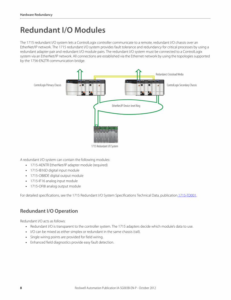
Redundant I/O ModulesThe 1715 redundant I/O system lets a ControlLogix controller communicate to a remote, redundant I/O chassis over an EtherNet/IP network. The 1715 redundant I/O system provides fault tolerance and redundancy for critical processes by using a redundant adapter pair and redundant I/O module pairs. The redundant I/O system must be connected to a ControlLogix system via an EtherNet/IP network. All connections are established via the Ethernet network by using the topologies supported by the 1756-EN2TR communication bridge.
A redundant I/O system can contain the following modules:• 1715-AENTR EtherNet/IP adapter module (required)• 1715-IB16D digital input module• 1715-OB8DE digital output module• 1715-IF16 analog input module• 1715-OF8I analog output module
For detailed specifications, see the 1715 Redundant I/O System Specifications Technical Data, publication 1715-TD001.
Redundant I/O Operation
Redundant I/O acts as follows:• Redundant I/O is transparent to the controller system. The 1715 adapters decide which module’s data to use.• I/O can be mixed as either simplex or redundant in the same chassis (rail).• Single wiring points are provided for field wiring.• Enhanced field diagnostics provide easy fault detection.
EtherNet/IP™ EtherNet/IP™REDUNDANCY MODULE
RUN SD OKFORCE
Logix5575
RUN SD OKFORCE
Logix5575 EtherNet/IP™ EtherNet/IP™REDUNDANCY MODULE
RUN SD OKFORCE
Logix5575
RUN SD OKFORCE
Logix5575
ControlLogix Primary Chassis ControlLogix Secondary Chassis
1715 Redundant I/O System
EtherNet/IP Device-level Ring
Redundanct Crossload Media
8 Rockwell Automation Publication IA-SG003B-EN-P - October 2012

Hardware Redundancy
Resilient EtherNet/IP MediaEmbedded switch technology is designed to enable end devices to form linear and ring network topologies.
Products with EtherNet/IP embedded switch technology have two ports to connect to a linear or DLR network in a single subnet. You cannot use these ports as two network interface cards connected to two different subnets.
Linear Network
A linear network is a collection of daisy-chained devices. The EtherNet/IP embedded switch technology allows this topology to be implemented at the device level. No additional switches are required.
These are the primary advantages of a linear network:• The network simplifies installation and reduces wiring and installation costs.• The network requires no special software configuration.• Embedded switch products offer improved CIP Sync application performance on linear networks.
The primary disadvantage of a linear network is that any break of the cable disconnects all devices downstream from the break from the rest of the network.
EtherNet/IP™
Rockwell Automation Publication IA-SG003B-EN-P - October 2012 9

Hardware Redundancy
Device-level Ring (DLR) Network
A DLR network is a single-fault tolerant ring network intended for the interconnection of automation devices. This topology is also implemented at the device level. No additional switches are required.
The advantages of the DLR network include the following:• Simple installation• Resilience to a single point of failure on the network• Fast recovery time when a single fault occurs on the network
The primary disadvantage of the DLR topology is the additional effort required to set up and use the network as compared to a linear or star network.
EtherNet/IP Resiliency Protocols
The choice of EtherNet/IP topology and protocol is application dependent.
Protocol Mixed Vendor Ring Redundant Star Network Convergence > 250 ms
Network Convergence 60…100 ms
Network Convergence 1…3 ms
STP (802.1D) X X X
RSTP (802.1w) X X X X
MSTP (802.1s) X X X X
rPVST+ X X X
REP X X
EtherChannel (LACP 802.3ad) X X X
Flex Links X X
DLR (embedded switch technology) X X X
00:00:BC:66:0F:C7
DCOUTPUT
DCINPUT
24 VDCSOURCE
24 VDCSINK
RUN NS
FORCE LINK 1
I/O LINK 2
OK SD
8 9 10 11 12 13 14 15
0
8
1
9
2
10
3
11
4
12
5
13
6
14
7
0 1 2 3 4 5 6 7
15
DCINPUT
24 VDCSINK
0 81 92 103 11VDC
+
VDC-
CG
FP+
FP-
4 125 136 147 15V VV V
DCOUTPUT
24 VDCSOURCE
0 81 92 103 114 125 136 147 15C CC C
WARNINGEXPLOSION HAZARD
Do Not DisconnectWhile Circuit Is Live
Unless Area IsKnown To Be
Non-Hazardous
EtherNet/IP™
350
MEM
A=ENABLEB= REGENC=DATA ENTRYD=FAULTE=COM ACTIVITY
24VDCINPUT
BRAKE/DC BUS
AB
DE
C
ETHERN
ETM
ORTO
R FEEDBACK
10 Rockwell Automation Publication IA-SG003B-EN-P - October 2012

Hardware Redundancy
Redundant ControlNet MediaRedundant ControlNet media requires these components:
• Redundant ControlNet scanner• Two identical ControlNet links
Redundant Power SuppliesA redundant power supply system provides additional uptime protection for chassis used in critical applications. The redundant power supplies funnel power through the chassis adapter module to the ControlLogix Series B chassis backplane.
For a redundant power supply system, you need the following components:• Two of the same redundant power supplies (two 1756-PA75R or two 1756-PB75R)• One 1756-PSCA2 chassis adapter module• Two 1756-CPR2 cables to connect the power supplies to the 1756-PSCA2 chassis adapter module (0.91 m [3 ft] length)• User-supplied annunciator wiring to connect the power supplies to the input modules, as needed
The 1756-PSCA2 chassis adapter module is a passive device that funnels power from the redundant power supplies to the single power connector on the ControlLogix Series B chassis backplane.
EtherNet/IP™ REDUNDANCY MODULE
RUN SD OKFORCE
Logix5575
RUN SD OKFORCE
Logix5575
ControlNet NodeControlNet Node
Redundant ControlNet Media
• ControlLogix Controller• 1756-CN2R or 1756-CNBR
1756-PA75R or 1756-PB75R Redundant Power Supplies
ControlLogix
1756-PSCA2 Chassis Adapter
1756-CPR2 Cables
Rockwell Automation Publication IA-SG003B-EN-P - October 2012 11

Hardware Redundancy
Notes:
12 Rockwell Automation Publication IA-SG003B-EN-P - October 2012
Hot Backup
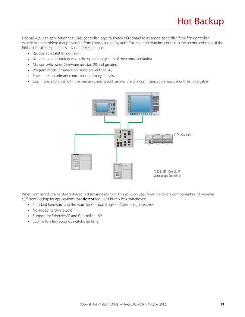
Hot backup is an application that uses controller logic to switch I/O control to a second controller if the first controller experiences a problem that prevents it from controlling the system. This solution switches control to the second controller if the initial controller experiences any of these situations:
• Recoverable fault (major fault)• Nonrecoverable fault (such as the operating system of the controller faults)• Manual switchover (firmware revision 20 and greater)• Program mode (firmware revisions earlier than 20)• Power loss on primary controller or primary chassis• Communication loss with the primary chassis, such as a failure of a communication module or break in a cable
When compared to a hardware-based redundancy solution, this solution uses fewer hardware components and provides sufficient backup for applications that do not require a bump-less switchover:
• Standard hardware and firmware for CompactLogix or ControlLogix systems• No added hardware cost • Support for EtherNet/IP and ControlNet I/O • 250 ms to a few seconds switchover time
RUN
REM
PROG
LINK 1
LINK 2
NS
SD
RUN
FORCE
I/O
OK
XX:XX:XX:XX:XX:XX
L33ERM
1 (Front)2 (Rear)
RUN
REM
PROG
LINK 1
LINK 2
NS
SD
RUN
FORCE
I/O
OK
XX:XX:XX:XX:XX:XX
L33ERM
1 (Front)2 (Rear)
1769-L30ER, 1769-L33ER CompactLogix Controllersz
FLEX I/O Module
Rockwell Automation Publication IA-SG003B-EN-P - October 2012 13

Hot Backup
To use a hot back-up solution, you must be able to tolerate all of the following criteria:• A delay of several milliseconds to several seconds may occur before the secondary controller gains full control of the
system.• During the switchover, outputs may temporarily revert to the values for Fault mode, according to the I/O configuration
for the modules. We recommend last state during switchover whenever possible.• Hot backup does not support any motion module, such as 1756-M02AE or1756-M08SE.• Ethernet modules do not swap I/P addresses.• Use 1756 or 1794 I/O modules only. 1734 POINT I/O modules are not supported.• Output modules must be in a remote chassis. • We recommend placing input modules and output modules in separate chassis.• Hot backup supports I/O on ControlNet and EtherNet/IP networks only. Firmware revisions 20 and greater support I/O on
EtherNet/IP networks only.• Controllers must stay in Remote mode. The application will switch once but will not qualify the secondary controller if
either one is in hard Run mode.
Switchover Delay
The switchover of control from one controller to another does not occur immediately. The delay could range from hundreds of milliseconds to several seconds or longer, and depends on these factors:
• Size of the system• Quantity of I/O in the system• Distribution of the output modules in the remote chassis• Speed of the system• Type of failure
– If a controller enters Fault or Program mode, it must close its connections to the output modules before the secondary controller can take over control. (Program mode supported only in firmware revisions earlier than 20.)
– If a controller fails or loses communication to the system, its connections close, so the secondary controller can take over control as soon as the failure is detected.
The HMI delay depends on the solution you use to switch topics to the other controller. This switchover takes 2…15 seconds and may cause a bump in the I/O control.
For more information, see Knowledgebase Answer ID 68593 at the Rockwell Automation Support Center
14 Rockwell Automation Publication IA-SG003B-EN-P - October 2012


Publication IA-SG003B-EN-P - October 2012Supersedes Publication IA-SG003A-EN-P - July 2012 Copyright © 2012 Rockwell Automation, Inc. All rights reserved. Printed in the U.S.A.
Allen-Bradley, Rockwell Software, Rockwell Automation, LISTEN. THINK. SOLVE, CompactLogix, ControlLogix, POINT I/O, PowerFlex are trademarks of Rockwell Automation, Inc
Trademarks not belonging to Rockwell Automation are property of their respective companies.