high-acceleration micro-scale laser sails for …. kare 2/15/02 high acceleration micro-scale laser...
TRANSCRIPT

J. Kare 2/15/02 High Acceleration Micro-scale Laser Sails 1 of 39
High-acceleration Micro-scale Laser Sails for Interstellar Propulsion
Final ReportNIAC Research Grant #07600-070
31 December 2001 (Revised 15 Feb. 2002)
Dr. Jordin T. Kare
Kare Technical Consulting
222 Canyon Lakes Place [email protected]
San Ramon, CA 94583 925-735-8012
Table of Contents
Executive Summary ...................................................................................................................................... 2
Introduction: The SailBeam Concept .......................................................................................................... 4
Phase I Results .............................................................................................................................................. 6
Task I: Physical and Engineering Limits on SailBeam .......................................................................... 6
Sail Materials ........................................................................................................................................ 6
Multilayer Sails ..................................................................................................................................... 8
Flux Limits .......................................................................................................................................... 11
Tensile Limits ..................................................................................................................................... 14
Summary of Sail Materials ................................................................................................................. 15
Sail Stability ........................................................................................................................................ 16
Sail Guidance ...................................................................................................................................... 18
Sail Design Concept............................................................................................................................ 21
Sail-to-vehicle Coupling and MagSail Issues.................................................................................... 21
MagSail Braking ................................................................................................................................. 26
Task 2: System Parameters and Scaling................................................................................................ 28
Sail Velocity vs. Vehicle Velocity ..................................................................................................... 28
Point System Designs For a SailBeam Launcher .............................................................................. 29
Multiple Telescopes............................................................................................................................ 30
Scaling SailBeam Systems ................................................................................................................. 33
Scaling to Interstellar Precursor Missions ......................................................................................... 33
Task 3: Technology Roadmap............................................................................................................... 35
Technology Roadmap......................................................................................................................... 35
Near-Term Experiments ..................................................................................................................... 36
Conclusions ................................................................................................................................................. 37
References ................................................................................................................................................... 38

J. Kare 2/15/02 High Acceleration Micro-scale Laser Sails 2 of 39
Executive Summary
The SailBeam concept for interstellar propulsion uses a large (multi-GW) laser to accelerate a stream
of small laser sails to speeds of order 0.1 c. Each sail is a fractional-wavelength-thick film of very-low-
absorption dielectric material, such as diamond or glass, typically of order 10 cm in diameter, with a mass
of a few milligrams. The sails are accelerated by the pressure of the laser light they reflect, and because of
their low absorption, they can survive very high fluxes and accelerations, so the laser can launch one sail
every few seconds for a period of years. The resulting “beam” of millions of sails is used to push an
interstellar vehicle, which may mass several tons, up to close to the sail velocity. The sails transfer their
momentum to the probe by being converted to plasma and reflected from a probe-generated magnetic field
(a MagSail).
After several years of acceleration, the probe coasts to its destination, and uses its reconfigured
MagSail as a drag brake against the interstellar medium and the target star’s stellar wind, allowing the
probe to slow essentially to rest in the target system.
The purpose of the Phase 1 NIAC study was to attempt to understand the physical feasibility and
physical and engineering limitations of the SailBeam concept, and to develop a system model to help
understand the scaling of a SailBeam system.
The key results of the Phase 1 study are as follows:
1. No show stoppers were found; SailBeam can be made to work assuming only known physics and
materials, although maximum system performance depends on improvements in materials, especially
sail properties.
2. The most serious current limitation appears to be the relatively high absorption of real thin films,
typically 10-5 of the incident flux, as compared to the desired absorption of less than 10-8. If lower-
absorption films cannot be fabricated, then SailBeam will still work, but will need to use larger, lower-
acceleration sails, with an associated penalty in the achievable velocity or the required laser and
telescope size. However, the prospects for making lower-absorption films are good.
3. The most promising sail material is artificial diamond film, due to its high refractive index, low density,
and good mechanical properties. Diamond provides much higher performance than glass, which was
the original concept baseline. Alternatives include zirconium oxide, titanium oxide, silicon
(transparent in the mid-infrared), glass (doped SiO2) and pure SiO2.
4. Two- to four-layer sails are desirable to make efficient use of laser power. The reflectivity of a single
quarter-wavelength layer of glass is only 19%, while the reflectivity of three quarter-wavelength glass
layers spaced a quarter wavelength apart is 79%, reducing the laser power needed to accelerate a given
mass of sails by a factor of 4.
5. MagSail coupling of microsail momentum is feasible, although it may drive the minimum vehicle mass.
Sails can be converted to plasma by a kilojoule-class ultraviolet laser mounted on the vehicle, and
reflected from a ~0.1 T field generated by a superconducting loop with a 100 m radius carrying 1.6 x
107 amperes. The mass of such a loop is about 1000 kg with foreseeable superconductor technology.
6. A SailBeam-launched probe can decelerate by using its MagSail to drag against the ionized component
of the interstellar medium, although the MagSail loop should be redeployed to a larger radius and

J. Kare 2/15/02 High Acceleration Micro-scale Laser Sails 3 of 39
lower field configuration for optimum braking. Braking from 0.1 c to ~100 km/s takes typically 3
decades, consistent with 50 - 100 year interstellar travel times at 0.1 c. Faster deceleration may be
possible using the M2P2 mini-magnetosphere sail concept.
The drag of the MagSail in its launch configuration is significant compared to the average SailBeam
thrust. We solve this by using a novel MagSail configuration, cancelling the SailBeam coupling field
at large distances with the field from a larger, lower-current loop.
7. SailBeam scales poorly to low-velocity missions (below ~1% of c), including interstellar precursor
missions, due to the inherent energy-inefficiency of using photon momentum for propulsion at low
velocities. Using high-velocity microsails to carry kinetic energy, rather than momentum, is more
flexible and efficient than the basic SailBeam concept, but requires more complex vehicles and still
needs very large lasers and optics for the sail launcher. There may be ways to improve the
performance of a SailBeam system for low-velocity missions, but a more promising option is to use the
same technologies (large lasers and optics) for direct energy transmission, with laser-thermal or laser-
electric propulsion.
8. We developed preliminary concepts for sail stabilization and active sail guidance, but additional work is
needed to refine these approaches. Active guidance is needed to enable the sails to intercept the
vehicle over light-year distances, and can be implemented using simple photosensors and
microelectronic/micromechanical hardware carried by the microsails.
Finally, a notable recent insight which we are still trying to understand the impact of:
9. The telescope requirements for SailBeam can be further reduced by using multiple “relay” telescopes
spaced along the acceleration path. This also allows considerable extra system design freedom,
including the ability to reduce the sail flux and acceleration and to use multiple smaller lasers to
replace one large laser.
Based on all of the above, a preliminary technology and mission roadmap has been devised, in which
a SailBeam-based interstellar mission architecture is developed as the ultimate product of many threads,
including solar power satellites, laser propulsion, large space optics, solar sails, and MagSails.
We have also defined a program of experiments to determine the properties of existing thin-film
materials and demonstrate the feasibility of high-acceleration microsails, as a first step toward a true
SailBeam technology development program.

J. Kare 2/15/02 High Acceleration Micro-scale Laser Sails 4 of 39
High-acceleration Micro-scale Laser Sails for Interstellar Propulsion
Final ReportNIAC Research Grant #07600-070
31 December 2001 (revised 15 Feb. 2002)
Dr. Jordin T. Kare
Kare Technical Consulting
222 Canyon Lakes Place [email protected]
San Ramon, CA 94583 925-735-8012
Introduction: The SailBeam Concept
Background
The fact that light carries momentum is well known; the momentum flux associated with a beam of
power P is P/c, where c is the velocity of light. Bouncing a beam of light off a mirror delivers a thrust of
2P/c, or 6.6 N/GW, to the mirror. Laser beams have been used to levitate microscopic particles against
gravity, and recently, modest acceleration of macroscopic carbon film sections by laser pulses has been
demonstrated [1] as well as levitation of carbon mesh by microwave-beam momentum [2]. Laser-driven
sails for interstellar propulsion have been proposed and analyzed by several authors. [3, 4]
Until recently, laser sails were presumed to be limited to modest accelerations. Acceleration of a sail
is limited by the ratio of mass per unit area to flux,
a = 2 R φ / σ c
where R is the sail reflectivity, φ the flux, and σ the sail mass per unit area.
Flux in turn is limited by the heating of the sail due to absorbed laser energy. The best performance
was expected to be associated with thin (~1 skin depth, 10’s of nm) metallic films, possibly further reduced
in weight by forming the films into subwavelength-scale open meshes. Such a sail is limited by the ratio of
laser-wavelength absorption to infrared emissivity, with even idealized metals (1% absorption, 100%
emissivity) limited to less than 107 W/m2. The corresponding sail acceleration limit is a few 10’s of m/s2,
depending on the mean film thickness and metal density.
Previous concepts for laser sails were limited by the combination of this low acceleration and
diffraction, requiring extremely large transmitting optics and sail diameters (up to thousands of kilometers)
to achieve enough laser range to reach useful interstellar velocities, somewhat arbitrarily defined as 30,000
km/s or 0.1 c. This scaling led to minimum laser powers measured in terawatts, even for the thinnest
reflective films.
The SailBeam Concept
SailBeam, as proposed by Kare [5] is a hybrid of laser-driven sails and particle beam propulsion [6];
the momentum of a high-power laser beam is used to accelerate a stream of small, very low-mass

J. Kare 2/15/02 High Acceleration Micro-scale Laser Sails 5 of 39
microsails to high velocity, and the microsails transfer their momentum to a much larger mission vehicle,
as shown in Figure 1.
Laser acceleration of microsails is made (comparatively) practical by the use of low-absorption
quarter-wavelength-thick dielectric sails, as proposed by Landis [7]. Dielectric sails have significantly
lower reflectivity than metal sails. However, the light not reflected by a dielectric sail is primarily
transmitted, rather than absorbed. For specific wavelengths, high-purity glasses used in optical fibers can
now be manufactured with 1/e absorption lengths of order 20 km.
As intially conceived, SailBeam would have used glass-film sails, with refractive index n~1.6 and
reflectivity R ~ 0.19. For wavelengths near 1 micron and n = 1.6, λ/4 is ~1.5 x 10⁻⁷ m, and the absorption
of a λ/4 film can be of order 10-12. Even for very low infrared emissivity, this means that the thermally-
limited flux will exceed the surface-breakdown flux, which is characteristically 1013 to 1014 W/m2 at
visible wavelengths. A preliminary calculation then led to the limiting case cited in the proposal and
shown in Table 1.
Table 1: Sail parameters for the original high-acceleration microsail concept
Wavelength 1 µm
Density 2.6 g/cm3
Index of refraction 1.6
Reflection coefficient 0.19
Sail thickness 0.156 µm
Maximum laser flux 1014 W/m2
Absorption 10-12
Infrared emissivity 0.01 (nominal)
Radiated power 125 W/m2
Operating temperature 684 K
Maximum force 125 kN/m2
Areal density 406 mg/m2
Maximum acceleration 3.3 x 10⁸ m/s2
i.e., a microsail capable of accelerating from rest to relativistic velocities in less than a second.
Backing off by a factor of 10 in acceleration led to the conceptual starting point for a 1000 kg probe
mission given in Table 2.
Momentum flux ~ ms * vs / t
Laser Power PtWavelength λ
“Telescope” Diameter Dt
N sails accelerate over distance r ~ R / N (vs. single sail of same total mass accelerating over R)
Beam of coasting microsails Vehicle
Figure 1: SailBeam Concept
J. Kare 2/15/02 High Acceleration Micro-scale Laser Sails 6 of 39
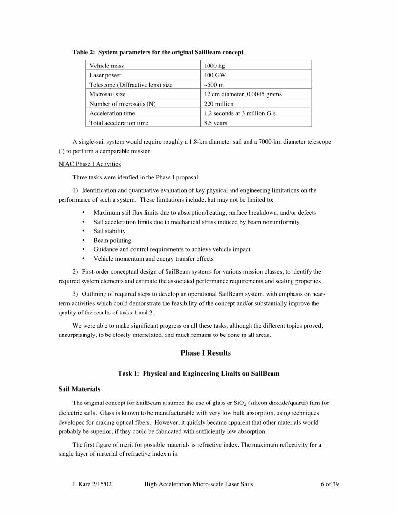
Table 2: System parameters for the original SailBeam concept
Vehicle mass 1000 kg
Laser power 100 GW
Telescope (Diffractive lens) size ~500 m
Microsail size 12 cm diameter, 0.0045 grams
Number of microsails (N) 220 million
Acceleration time 1.2 seconds at 3 million G’s
Total acceleration time 8.5 years
A single-sail system would require roughly a 1.8-km diameter sail and a 7000-km diameter telescope
(!) to perform a comparable mission
NIAC Phase I Activities
Three tasks were idenfied in the Phase I proposal:
1) Identification and quantitative evaluation of key physical and engineering limitations on the
performance of such a system. These limitations include, but may not be limited to:
• Maximum sail flux limits due to absorption/heating, surface breakdown, and/or defects
• Sail acceleration limits due to mechanical stress induced by beam nonuniformity
• Sail stability
• Beam pointing
• Guidance and control requirements to achieve vehicle impact
• Vehicle momentum and energy transfer effects
2) First-order conceptual design of SailBeam systems for various mission classes, to identify the
required system elements and estimate the associated performance requirements and scaling properties.
3) Outlining of required steps to develop an operational SailBeam system, with emphasis on near-
term activities which could demonstrate the feasibility of the concept and/or substantially improve the
quality of the results of tasks 1 and 2.
We were able to make significant progress on all these tasks, although the different topics proved,
unsurprisingly, to be closely interrelated, and much remains to be done in all areas.
Phase I Results
Task I: Physical and Engineering Limits on SailBeam
Sail Materials
The original concept for SailBeam assumed the use of glass or SiO2 (silicon dioxide/quartz) film for
dielectric sails. Glass is known to be manufacturable with very low bulk absorption, using techniques
developed for making optical fibers. However, it quickly became apparent that other materials would
probably be superior, if they could be fabricated with sufficiently low absorption.
The first figure of merit for possible materials is refractive index. The maximum reflectivity for a
single layer of material of refractive index n is:
J. Kare 2/15/02 High Acceleration Micro-scale Laser Sails 7 of 39
R n n [( ) /( )]= − +2 2 21 1
(The maximum reflectivity occurs when the layer thickness T is 1/4 wavelength, or (2n+1)/4
wavelengths; the first and second surface reflections are then in phase. The reflectivity varies
approximately as R = Rmax[1-cos(4πT/λ)] / 2
Most glass has an index of refraction of only ~1.5 to 1.6, depending on composition. Therefore the
reflectivity of a glass film is at most 0.19, so over 80% of the propulsive laser beam is transmitted, and
therefore wasted, with a simple glass sail.∗
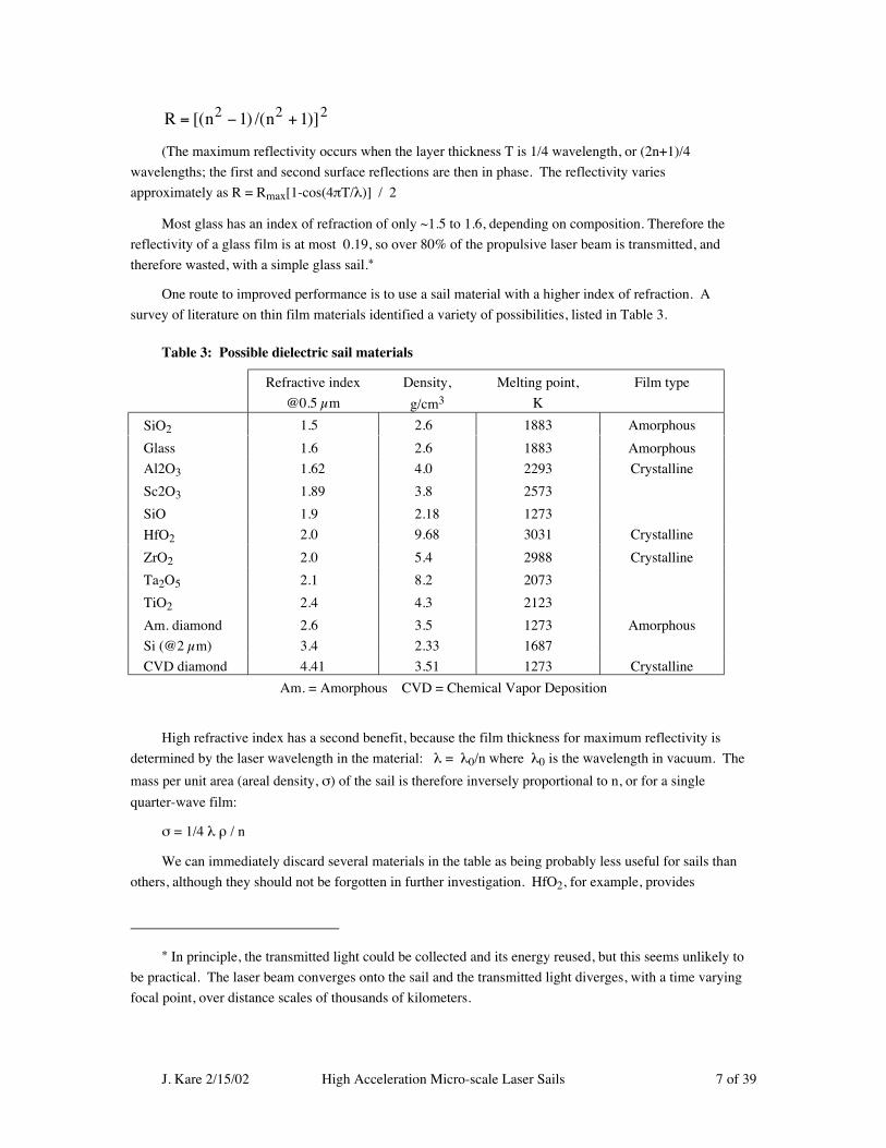
One route to improved performance is to use a sail material with a higher index of refraction. A
survey of literature on thin film materials identified a variety of possibilities, listed in Table 3.
Table 3: Possible dielectric sail materials
Refractive index
@0.5 µm
Density,
g/cm3
Melting point,
K
Film type
SiO2 1.5 2.6 1883 Amorphous
Glass 1.6 2.6 1883 Amorphous
Al2O3 1.62 4.0 2293 Crystalline
Sc2O3 1.89 3.8 2573
SiO 1.9 2.18 1273
HfO2 2.0 9.68 3031 Crystalline
ZrO2 2.0 5.4 2988 Crystalline
Ta2O5 2.1 8.2 2073
TiO2 2.4 4.3 2123
Am. diamond 2.6 3.5 1273 Amorphous
Si (@2 µm) 3.4 2.33 1687
CVD diamond 4.41 3.51 1273 Crystalline
Am. = Amorphous CVD = Chemical Vapor Deposition
High refractive index has a second benefit, because the film thickness for maximum reflectivity is
determined by the laser wavelength in the material: λ = λ0/n where λ0 is the wavelength in vacuum. The
mass per unit area (areal density, σ) of the sail is therefore inversely proportional to n, or for a single
quarter-wave film:
σ = 1/4 λ ρ / n
We can immediately discard several materials in the table as being probably less useful for sails than
others, although they should not be forgotten in further investigation. HfO2, for example, provides
∗ In principle, the transmitted light could be collected and its energy reused, but this seems unlikely to
be practical. The laser beam converges onto the sail and the transmitted light diverges, with a time varying
focal point, over distance scales of thousands of kilometers.

J. Kare 2/15/02 High Acceleration Micro-scale Laser Sails 8 of 39
essentially the same characteristics az ZrO2 but has a much higher density; Ta2O5 seems similarly
redundant to TiO2, at least initially.
Multilayer Sails
The initial SailBeam concept assumed a single layer λ/4 sail, since that would have the lowest areal
density and therefore, presumably, the highest acceleration for a given laser flux. This is true for high-
refractive-index materials (approximately n>2.2), but not for lower index materials. The reflectivity for an
ideal multilayer sail (L quarter-wavelength films separated by quarter-wavelength vacuum layers) is
R n nLL L [( ) /( )]= − +2 2 21 1
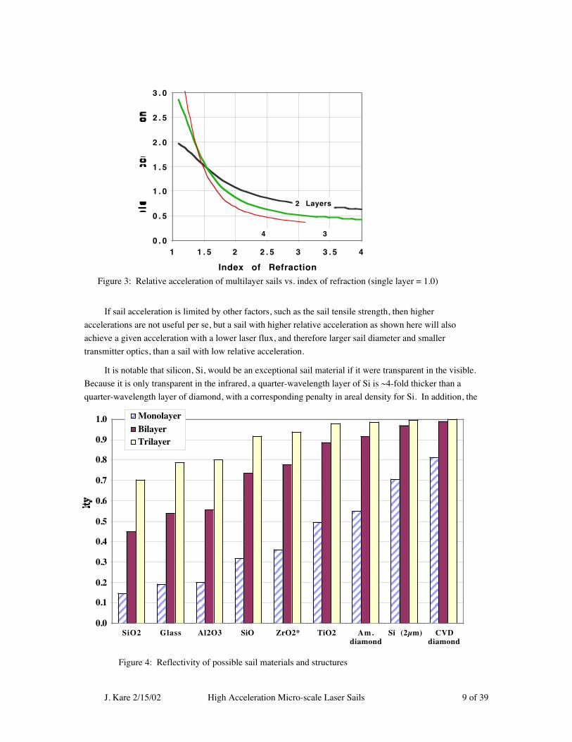
Figure 2 shows the reflectivities for one- to four-layer sails as a function of n; Figure 3 shows the
relative accelerations of one- to four-layer sails, assuming constant laser flux.
(A multilayer sail can also be made of alternating high- and low-refractive index materials, similar to
standard multilayer reflective coatings. The most likely dual-index sail would be a single 1/4 wave SiO2
layer, coated on both sides with a 1/4 wave layer of higher-index (but possibly lower-strength) material.)
It should be noted that Forward proposed a high-acceleration multilayer diamond laser sail in 1986
[8], although not in this range of accelerations; his sail was also considerably thicker than optimum for
maximum acceleration.
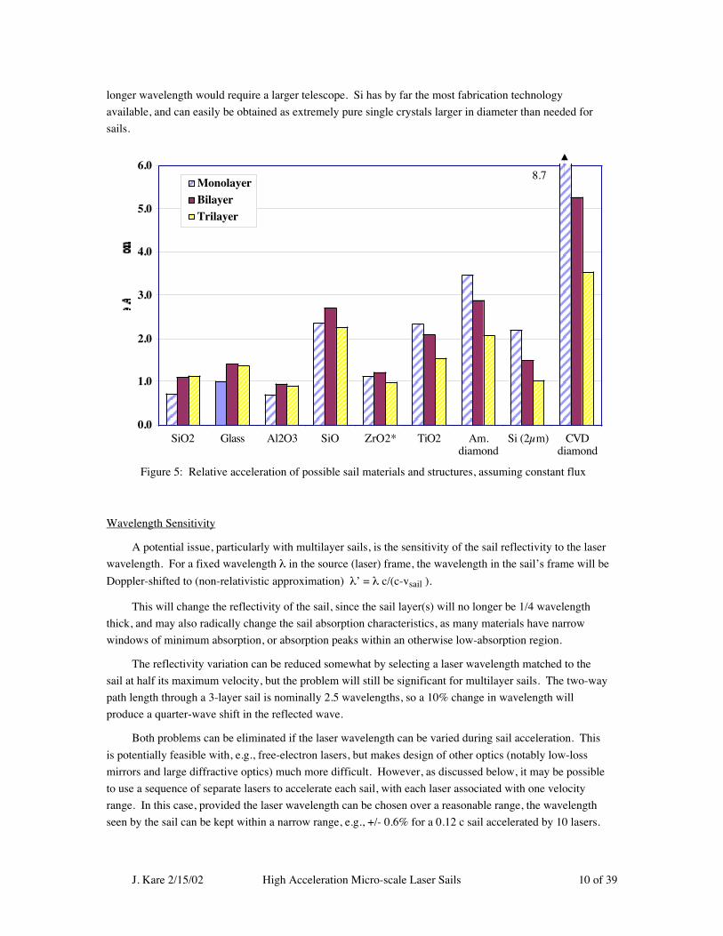
Figure 4 shows the relative reflectivities for different materials and sail designs. Figure 5 shows the
relative accelerations for different sail designs, with the (probably incorrect) assumption that all sail
materials can tolerate the same maximum flux Relative acceleration will be very important if the sails are
limited to comparatively low flux due to absorption and heating, since the required acceleration distance,
and thus the required transmitter aperture, will be large.
0
2 0
4 0
6 0
8 0
1 0 0
1 1 . 5 2 2 . 5 3 3 . 5 4
Index of Refraction
Single layer
2 Layers
34
Figure 2: Reflectivity vs. refractive index of multilayer sails
J. Kare 2/15/02 High Acceleration Micro-scale Laser Sails 9 of 39
If sail acceleration is limited by other factors, such as the sail tensile strength, then higher
accelerations are not useful per se, but a sail with higher relative acceleration as shown here will also
achieve a given acceleration with a lower laser flux, and therefore larger sail diameter and smaller
transmitter optics, than a sail with low relative acceleration.
It is notable that silicon, Si, would be an exceptional sail material if it were transparent in the visible.
Because it is only transparent in the infrared, a quarter-wavelength layer of Si is ~4-fold thicker than a
quarter-wavelength layer of diamond, with a corresponding penalty in areal density for Si. In addition, the
0 . 0
0 . 5
1 . 0
1 . 5
2 . 0
2 . 5
3 . 0
1 1 . 5 2 2 . 5 3 3 . 5 4
Index of Refraction
2 Layers
34
Figure 3: Relative acceleration of multilayer sails vs. index of refraction (single layer = 1.0)
Figure 4: Reflectivity of possible sail materials and structures
0.0
0.1
0.2
0.3
0.4
0.5
0.6
0.7
0.8
0.9
1.0
SiO2 Glass Al2O3 SiO ZrO2* TiO2 Am.diamond
Si (2µm) CVDdiamond
MonolayerBilayerTrilayer
J. Kare 2/15/02 High Acceleration Micro-scale Laser Sails 10 of 39
longer wavelength would require a larger telescope. Si has by far the most fabrication technology
available, and can easily be obtained as extremely pure single crystals larger in diameter than needed for
sails.
Wavelength Sensitivity
A potential issue, particularly with multilayer sails, is the sensitivity of the sail reflectivity to the laser
wavelength. For a fixed wavelength λ in the source (laser) frame, the wavelength in the sail’s frame will be
Doppler-shifted to (non-relativistic approximation) λ’ = λ c/(c-vsail ).
This will change the reflectivity of the sail, since the sail layer(s) will no longer be 1/4 wavelength
thick, and may also radically change the sail absorption characteristics, as many materials have narrow
windows of minimum absorption, or absorption peaks within an otherwise low-absorption region.
The reflectivity variation can be reduced somewhat by selecting a laser wavelength matched to the
sail at half its maximum velocity, but the problem will still be significant for multilayer sails. The two-way
path length through a 3-layer sail is nominally 2.5 wavelengths, so a 10% change in wavelength will
produce a quarter-wave shift in the reflected wave.
Both problems can be eliminated if the laser wavelength can be varied during sail acceleration. This
is potentially feasible with, e.g., free-electron lasers, but makes design of other optics (notably low-loss
mirrors and large diffractive optics) much more difficult. However, as discussed below, it may be possible
to use a sequence of separate lasers to accelerate each sail, with each laser associated with one velocity
range. In this case, provided the laser wavelength can be chosen over a reasonable range, the wavelength
seen by the sail can be kept within a narrow range, e.g., +/- 0.6% for a 0.12 c sail accelerated by 10 lasers.
Figure 5: Relative acceleration of possible sail materials and structures, assuming constant flux
0.0
1.0
2.0
3.0
4.0
5.0
6.0
SiO2 Glass Al2O3 SiO ZrO2* TiO2 Am.diamond
Si (2µm) CVDdiamond
MonolayerBilayerTrilayer
8.7
J. Kare 2/15/02 High Acceleration Micro-scale Laser Sails 11 of 39
Flux Limits
Dielectric sails are subject to the same thermal limits as metallic laser sails: the sail must reradiate as
much energy as it absorbs from the propulsive laser beam without exceeding its maximum operating
temperature. The time to accelerate a microsail is of order seconds, which is much longer than the time for
the sail to reach thermal equilibrium (in thickness, not across the sail diameter). The sail must therefore
radiate the same energy per unit area as it absorbs from the laser. The radiation flux nominally follows the
Stefan-Boltzman law, so:
φ < ε σB Tmax4 / α
where ε is the surface emissivity over the radiating wavelength range, σB is Boltzmann’s constant,
5.67 x 10⁻⁸ W/m2K4, and α is the sail absorption.
The operating flux, and thus the sail acceleration, can be increased by decreasing absorption,
increasing emissivity, or increasing operating temperature.
Absorption
A brief literature search was conducted to find typical values for the absorption characteristics of
actual thin films, with discouraging results. The absorption characteristics of highly-transparent films are
difficult to measure, since a direct measurement of intensity change is essentially impossible -- even if a
power or intensity measurement of sufficient precision were achievable, it would be extremely difficult to
distinguish among absorption, reflection, and scattering losses.
There is a substantial body of literature on techniques for measuring very low absorption levels by
observing, directly or indirectly, the temperature rise in a sample or its immediate environment when a
laser pulse is present. Unfortunately, even the most sensitive measurement techniques [9] are limited to
absorption factors of approximately 10-6. The measured absorption levels for most high-quality thin films
are in the range of 10-4 to 10-5.
This absorption is known to be several orders of magnitude higher than the bulk absorption of the film
materials. Indeed, commercial long-haul optical fiber (e.g., Lucent Technology AllWave fiber) is readily
available with attenuation coefficients below 0.25 dB/km at 1400 nm, corresponding to an absorption of 2.5
x 10-12 per micron.
The large absorption factors for thin films are thus due to a combination of surface effects, especially
at boundaries between different materials or between film materials and substrates, and volume effects
associated with defects and impurities. It is clear that the absorption characteristics are strongly
dependent on the details of the film preparation. Most optical coatings are not solid, but have a significant
void fraction and a microstructure that depends on the deposition technique [10]. In particular, the
absorption of current CVD diamond and other polycrystalline materials is commonly set by grain-boundary
effects. CVD diamond in particular has microcracks filled with non-diamond carbon, called black spots or
dark inclusions [11]. Ideally, microsails would be single crystals, or at least have very few grain
boundaries; this is clearly achievable with silicon but may or may not be possible with other crystalline
materials unless true atomic-scale nanofabrication becomes possible.
There are several possibilities for reducing absorption, including reducing impurities (except for
desired dopants) and changing material composition. Optimum thin-film fabrication techniques for
microsails may be significantly different from those for multilayer optical coatings on rigid substrates,

J. Kare 2/15/02 High Acceleration Micro-scale Laser Sails 12 of 39
especially if fabrication can be done in space, with unlimited ultrahigh vacuum and no gravity. Of
particular interest are applications of fiber optic and semiconductor techniques for microsail fabrication.
Operating Temperature
Other factors being equal, increasing a sail’s operating temperature rapidly increases its maximum
flux. This approach is being taken with both solar and laser sails using carbon-carbon sails, optionally
coated with refractory metal films [12]. If extremely low absorption is not achievable, high operating
temperature may be the best route to high acceleration. The bulk melting (or decomposition) temperatures
of possible sail materials are given in Table 3 above. Unfortunately, melting temperature gives only a
rough indication of maximum operating temperature, since both absorption and mechanical properties will
vary with temperature, and most materials will become unusable at some unknown temperature well below
melting.
However, taking melting temperature as a reasonable proxy for operating temperature, and assuming
constant absorption and emissivity, Figure 6 shows the relative acceleration of different materials if
acceleration is thermally limited. (This figure does not correct the absorption for the number of sail layers;
multilayer sails will have greater absorption than single layer sails, but not in proportion to the number of
layers, since “back” layers see a lower laser flux than the first layer.)
Emissivity
We were not able to find much information on the infrared emissivity of thin film materials. Most of
the prospective sail materials have reasonably strong absorption, and therefore high emissivity in bulk, in
the thermal infrared (8-14 µm), generally based on coupling to single-phonon vibrational modes in the
material. For example, fused silica (SiO2) has an absorption coefficient of >104 cm-1 from approximately
8.3 µm to 9.6 µm [13], which nominally corresponds to emissivity of order 0.1 for a 100 nm film.
0.0
1.0
2.0
3.0
4.0
5.0
6.0
7.0
8.0
SiO2 Glass Al2O3 SiO ZrO2* TiO2 Am.diamond
Si (2µm) CVDdiamond
MonolayerBilayer
Trilayer
Figure 6: Relative acceleration of microsails assuming flux proportional to T(melting)4
J. Kare 2/15/02 High Acceleration Micro-scale Laser Sails 13 of 39
However, the extrapolation to very thin layers is not obvious.
The exception is high-purity crystalline diamond, which is highly transparent in the thermal infrared,
due to a stiff lattice structure and a symmetrical lattice which suppresses single-phonon coupling [14]
CVD diamond is commonly used as a thermal-IR window material. The IR absorption coefficient for
diamond does increase with increasing temperature, and can be raised by inclusion of dopants (e.g. nitrogen
atoms) which disturb the symmetry of the lattice.
Modeling and/or experimentally measuring thin film emissivity to modest accuracy should not be
difficult, if a more extensive literature search does not yield sufficient information. For the purposes of
system analysis in this study, we have assumed that a thermal-band emissivity of 0.1 - 1% is typical.
Carbon Sails Vs. Dielectric Sails:
As noted above, Myrabo and others have recently done significant work on laser and solar
acceleration of carbon-fiber sails, optionally coated with refractory metal; this work has been stimulated by
the availability of carbon fiber “felt” materials with low areal density (~10-3 kg/m2, corresponding to an
actual material thickness of order 1 micron) and excellent mechanical properties. These materials can
operate at very high temperature and have excellent emissivity on the unmetallized side, and appear to be
nearly ideal for solar sails.
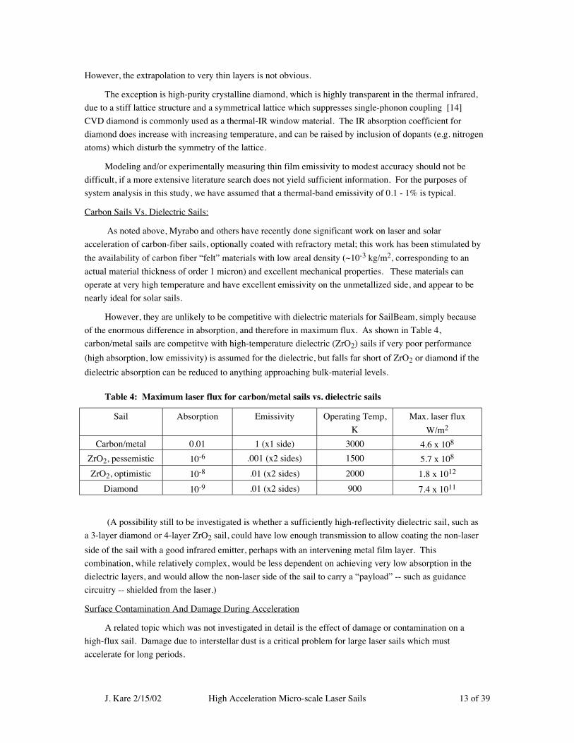
However, they are unlikely to be competitive with dielectric materials for SailBeam, simply because
of the enormous difference in absorption, and therefore in maximum flux. As shown in Table 4,
carbon/metal sails are competitve with high-temperature dielectric (ZrO2) sails if very poor performance
(high absorption, low emissivity) is assumed for the dielectric, but falls far short of ZrO2 or diamond if the
dielectric absorption can be reduced to anything approaching bulk-material levels.
Table 4: Maximum laser flux for carbon/metal sails vs. dielectric sails
Sail Absorption Emissivity Operating Temp,
K
Max. laser flux
W/m2
Carbon/metal 0.01 1 (x1 side) 3000 4.6 x 10⁸
ZrO2, pessemistic 10-6 .001 (x2 sides) 1500 5.7 x 10⁸
ZrO2, optimistic 10-8 .01 (x2 sides) 2000 1.8 x 10¹²
Diamond 10-9 .01 (x2 sides) 900 7.4 x 10¹¹
(A possibility still to be investigated is whether a sufficiently high-reflectivity dielectric sail, such as
a 3-layer diamond or 4-layer ZrO2 sail, could have low enough transmission to allow coating the non-laser
side of the sail with a good infrared emitter, perhaps with an intervening metal film layer. This
combination, while relatively complex, would be less dependent on achieving very low absorption in the
dielectric layers, and would allow the non-laser side of the sail to carry a “payload” -- such as guidance
circuitry -- shielded from the laser.)
Surface Contamination And Damage During Acceleration
A related topic which was not investigated in detail is the effect of damage or contamination on a
high-flux sail. Damage due to interstellar dust is a critical problem for large laser sails which must
accelerate for long periods.

J. Kare 2/15/02 High Acceleration Micro-scale Laser Sails 14 of 39
Fortunately, the probability of a sizeable dust particle impact on a microsail during acceleration is
reasonably low. The estimated mean density of dust particles in interplanetary space is ~0.5 x 10⁻⁶ per m3
with a typical particle diameter of 0.4 µm [15]. A typical sail sweeps out a volume of <106 m3 during
acceleration (a few x 104 km acceleration range, x 10-2 m2 sail area) so that the probability of even a single
dust particle impact is substantially less than 1. The impact probability will be further reduced because the
laser beam itself will push dust particles out of the sail path.
Surface contamination of a sail during manufacture or storage is probably a larger problem than dust
impacts, and the problem of cleaning a large area of submicron film remains open.
What is still not clear is what will happen once a defect occurs in a sail, whether due to an inherent
flaw, a surface dust particle, or an impact. The main concern is that the hot, possibly chemically or
structurally altered edges of a hole in the sail would absorb sufficient laser energy to cause the hole to
enlarge, destroying the sail. (An analogous process occurs in burning a piece of paper with a magnifying
glass in sunlight; the white paper absorbs little energy, but once a hole develops, the charred edges of the
hole are efficient absorbers and the hole tends to grow rapidly). Whether this occurs will depend on the
thermal and optical properties of the sail film, and the threshold for failure for particular materials can
probably best be determined by experiment.
Other Flux Limits
There is an extensive literature on flux limits and failure mechanisms of dielectric coatings, but
unfortunately virtually all of it deals with coatings subjected to short (microsecond to subnanosecond) laser
pulses. For 10-nanosecond pulses, the fluence to damage a coating can be >40 J/cm2 (e.g., [16]), which
corresponds to a very high flux -- in excess of 4 x 10¹³ W/m2. Damage mechanisms at these short pulse
lengths are still poorly understood.
Most of the recent data available are for SiO2 and HfO2 films, since these are the most common
materials used for multilayer reflective coatings on high-peak-power optics, but other dielectric oxides are
apparently similar. Some data are available on SiO2 and HfO2 monolayers, but not on free-standing films;
the monolayer results are strongly substrate-dependent [17]. We have not found data on damage thresholds
for either diamond or silicon films.
In terms of fluence (energy per unit area) the damage threshold generally increases for longer pulses,
but much more slowly than linearly. Unfortunately, this means that in terms of flux, the damage threshold
decreases for longer pulse lengths. For example, reflective coatings tested with with 8 µs pulses had
damage thresholds of up to 150 J/cm2 [18], but the longer pulse means that this is less than 2 x 10¹¹ W/m2.
We found no useful data for pulses long enough to represent steady-state conditions for thin films (although
our search was by no means comprehensive).
A more comprehensive literature search may be valuable, but because no other system has involved
the combination of freestanding films, high flux, and long pulses (effectively steady-state operation),
experimental testing of possible sail films will be needed to determine realistic damage thresholds.
Tensile Limits
To keep the laser range short, microsails must be accelerated very quickly, and are therefore subject to
large accelerations -- typically >106 m/s2 -- and therefore to large forces. The very thin sails have very

J. Kare 2/15/02 High Acceleration Micro-scale Laser Sails 15 of 39
limited strength against buckling, and will need to be maintained in tension, by some combination of
centrifugal force and compressive structure, such as a hoop over which the sail film is stretched. (The
problem can be envisioned as comparable to that of keeping a large plastic garbage bag flat and unwrinkled
in a hurricane). The sail material will also be stressed in tension by either nonuniform illumination or
nonuniform areal density; the latter includes the effect of “payload” mass (such as MEMS guidance
hardware) that must be carried by the sail.
The characteristic maximum tensile stress Smax on the sail is approximately:
Smax = 2 R P / c d Tm = 8 n R P / c d L λ0
which represents the entire acceleration force applied to the cross-sectional area of the sail material
(diameter d * material thickness Tm) and L is the number of layers in the sail. For a nominal 2-layer
diamond sail (P=25 GW, d=0.26 m), Smax is 11 GPa.
The actual stress due to acceleration will typically be much less than Smax, assuming the laser force is
distributed reasonably uniformly over the sail mass. The major issue is what spin rate, and thus what
centrifugal force, must be applied both to stabilize the sail and to support mass not uniformly distributed.
Very roughly, it seems plausible that actual sails can be designed with S ~0.1 Smax, but no calculations
have been completed.
The tensile strength of thin films is not generally well characterized, but some values found in the
literature are given in Table 5.
Table 5: Sample tensile strengths of sail film materials
Material Tensile Strenght, GPa
SiO2 1.6-2.3
Al2O3 0.25
CVD diamond 3.5
Si 0.6 - 1.2
For the baseline levels of acceleration, a diamond sail with S = 0.1 Smax would have a reasonable
margin of tensile strength, but other materials would be marginal. Thus tensile strength may be a significant
system design driver in the direction of lower sail acceleration, unless clever sail design can minimize the
actual stress level relative to Smax.
It may also be feasible to include reinforcements on the back side of a high-reflectance sail. However,
few materials are significantly stronger in tension than CVD diamond, so diamond film itself is the most
obvious reinforcement for other materials. Carbon nanotubes have even higher tensile strength than
diamond, and a possible future research topic would be the properties and potential fabrication techniques
for nanotube-reinforced dielectric films.
Summary of Sail Materials
1. The most promising sail material is diamond film, based on its high index of refraction, low
density, reasonably high operating temperature, and high tensile strength. Diamond films need to be
evaluated for absorption and infrared emissivity characteristics.
J. Kare 2/15/02 High Acceleration Micro-scale Laser Sails 16 of 39
2. Si films have high index, low density, high strength, and high operating temperature, and can be
fabricated as single-crystal, polycrystalline, or amorphous films. However, Si is opaque in the visible, and
thus must be used with a short-wave infrared laser (nominally 2 µm) which means the film thickness is
much greater than for visibly-transparent materials operating at ~500 nm.
3. ZrO2 films have high operating temperature and moderate- refractive index, and will be preferred
if absorption cannot be reduced much below the currently-typical thin-film absorption levels, since they can
compensate for high absorption by high reradiation rates.
4. SiO2 and glass films may be preferred because of their ease of fabrication and the large body of
knowledge on making low-absorption glass; if so, the low index of refraction will require 3- or 4-layer sails
to make efficient use of the laser power.
Sail Stability
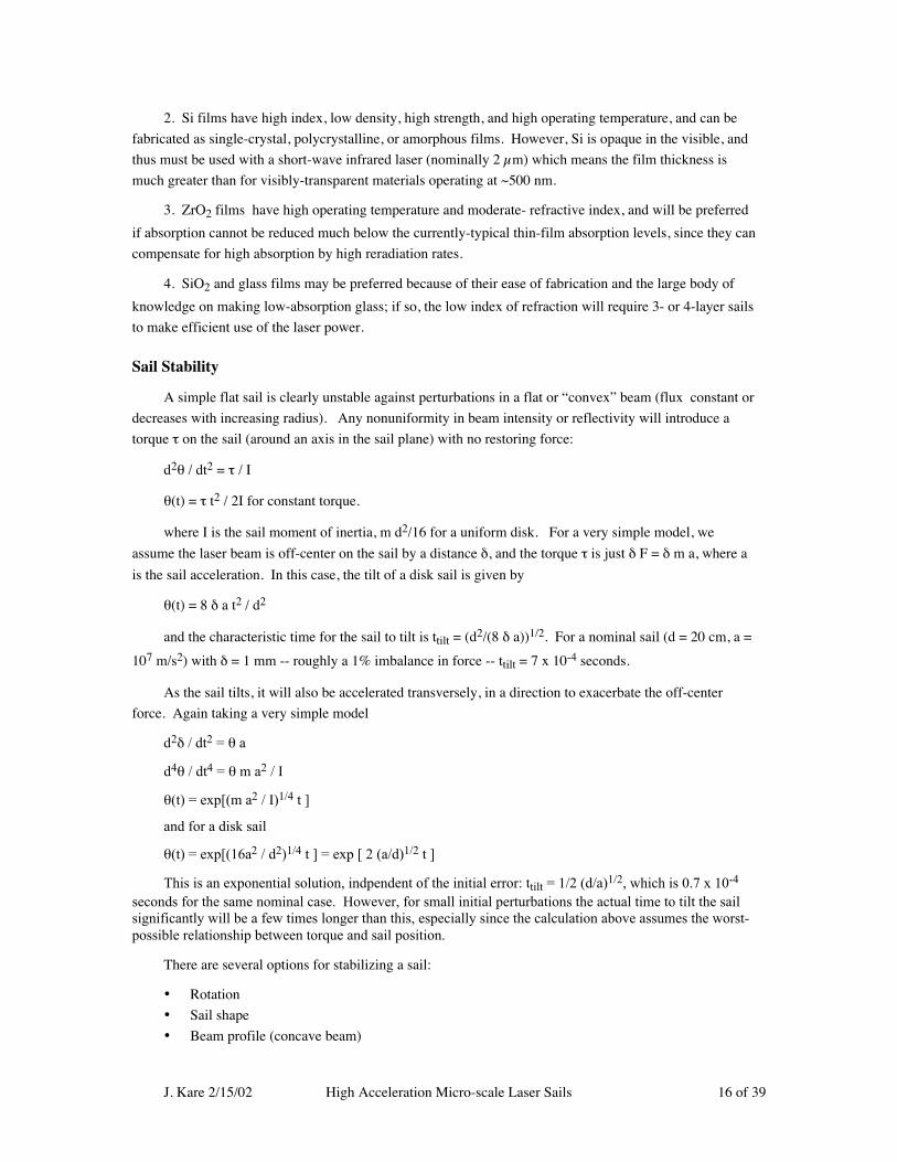
A simple flat sail is clearly unstable against perturbations in a flat or “convex” beam (flux constant or
decreases with increasing radius). Any nonuniformity in beam intensity or reflectivity will introduce a
torque τ on the sail (around an axis in the sail plane) with no restoring force:
d2θ / dt2 = τ / I
θ(t) = τ t2 / 2I for constant torque.
where I is the sail moment of inertia, m d2/16 for a uniform disk. For a very simple model, we
assume the laser beam is off-center on the sail by a distance δ, and the torque τ is just δ F = δ m a, where a
is the sail acceleration. In this case, the tilt of a disk sail is given by
θ(t) = 8 δ a t2 / d2
and the characteristic time for the sail to tilt is ttilt = (d2/(8 δ a))1/2. For a nominal sail (d = 20 cm, a =
107 m/s2) with δ = 1 mm -- roughly a 1% imbalance in force -- ttilt = 7 x 10⁻⁴ seconds.
As the sail tilts, it will also be accelerated transversely, in a direction to exacerbate the off-center
force. Again taking a very simple model
d2δ / dt2 = θ a
d4θ / dt4 = θ m a2 / I
θ(t) = exp[(m a2 / I)1/4 t ]
and for a disk sail
θ(t) = exp[(16a2 / d2)1/4 t ] = exp [ 2 (a/d)1/2 t ]
This is an exponential solution, indpendent of the initial error: ttilt = 1/2 (d/a)1/2, which is 0.7 x 10⁻⁴
seconds for the same nominal case. However, for small initial perturbations the actual time to tilt the sailsignificantly will be a few times longer than this, especially since the calculation above assumes the worst-possible relationship between torque and sail position.
There are several options for stabilizing a sail:
• Rotation
• Sail shape
• Beam profile (concave beam)
J. Kare 2/15/02 High Acceleration Micro-scale Laser Sails 17 of 39
• Active sail
• Active beam tracking
• External control
Of these, active beam tracking (manipulating the propulsion laser beam based on feedback about the
sail attitude and position) is easily eliminated as being too slow, since the control delay is typically several
hundred milliseconds (speed of light round trip time from sail to laser and back) even with instantaneous
response by the laser. This is orders of magnitude longer than the characteristic time for sail instabilities.
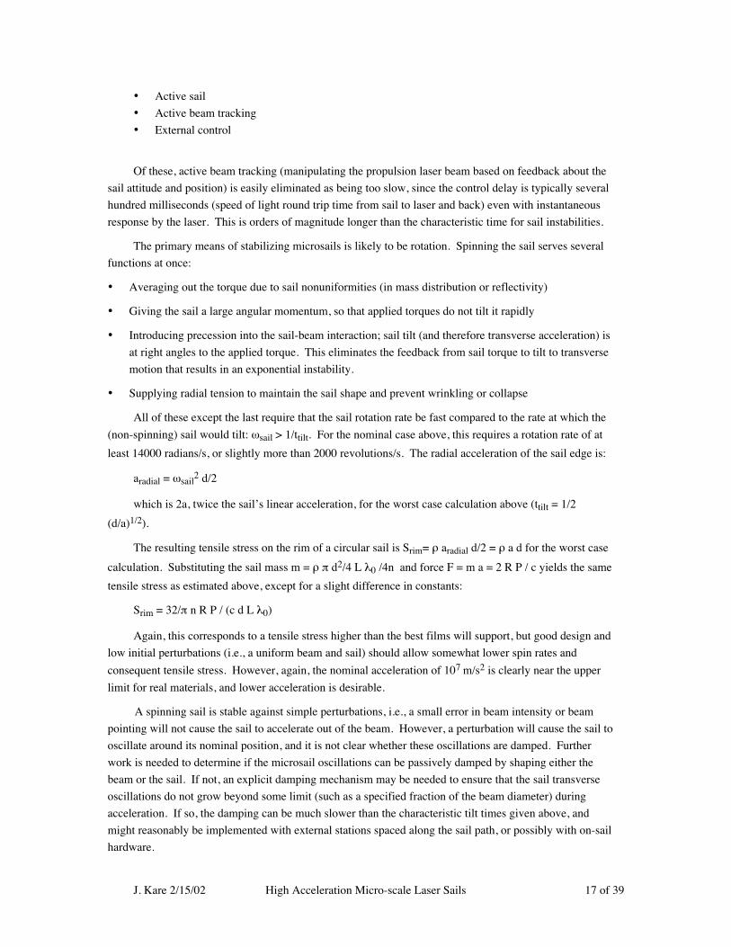
The primary means of stabilizing microsails is likely to be rotation. Spinning the sail serves several
functions at once:
• Averaging out the torque due to sail nonuniformities (in mass distribution or reflectivity)
• Giving the sail a large angular momentum, so that applied torques do not tilt it rapidly
• Introducing precession into the sail-beam interaction; sail tilt (and therefore transverse acceleration) is
at right angles to the applied torque. This eliminates the feedback from sail torque to tilt to transverse
motion that results in an exponential instability.
• Supplying radial tension to maintain the sail shape and prevent wrinkling or collapse
All of these except the last require that the sail rotation rate be fast compared to the rate at which the
(non-spinning) sail would tilt: ωsail > 1/ttilt. For the nominal case above, this requires a rotation rate of at
least 14000 radians/s, or slightly more than 2000 revolutions/s. The radial acceleration of the sail edge is:
aradial = ωsail2 d/2
which is 2a, twice the sail’s linear acceleration, for the worst case calculation above (ttilt = 1/2
(d/a)1/2).
The resulting tensile stress on the rim of a circular sail is Srim= ρ aradial d/2 = ρ a d for the worst case
calculation. Substituting the sail mass m = ρ π d2/4 L λ0 /4n and force F = m a = 2 R P / c yields the same
tensile stress as estimated above, except for a slight difference in constants:
Srim = 32/π n R P / (c d L λ0)
Again, this corresponds to a tensile stress higher than the best films will support, but good design and
low initial perturbations (i.e., a uniform beam and sail) should allow somewhat lower spin rates and
consequent tensile stress. However, again, the nominal acceleration of 107 m/s2 is clearly near the upper
limit for real materials, and lower acceleration is desirable.
A spinning sail is stable against simple perturbations, i.e., a small error in beam intensity or beam
pointing will not cause the sail to accelerate out of the beam. However, a perturbation will cause the sail to
oscillate around its nominal position, and it is not clear whether these oscillations are damped. Further
work is needed to determine if the microsail oscillations can be passively damped by shaping either the
beam or the sail. If not, an explicit damping mechanism may be needed to ensure that the sail transverse
oscillations do not grow beyond some limit (such as a specified fraction of the beam diameter) during
acceleration. If so, the damping can be much slower than the characteristic tilt times given above, and
might reasonably be implemented with external stations spaced along the sail path, or possibly with on-sail
hardware.
J. Kare 2/15/02 High Acceleration Micro-scale Laser Sails 18 of 39
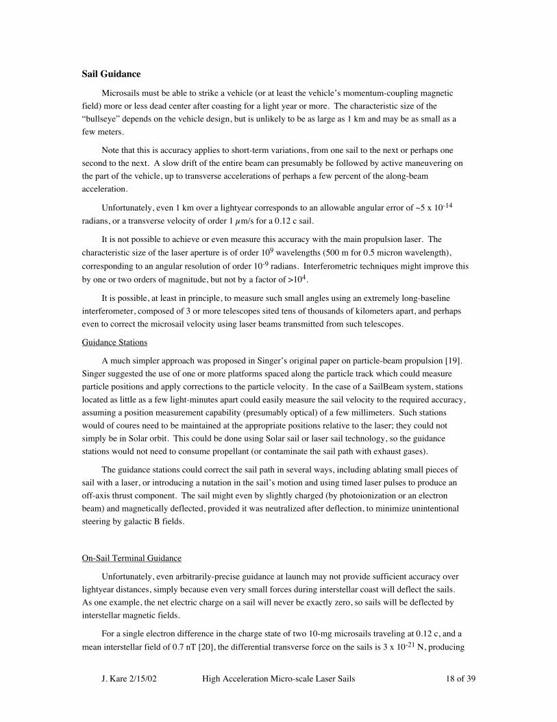
Sail Guidance
Microsails must be able to strike a vehicle (or at least the vehicle’s momentum-coupling magnetic
field) more or less dead center after coasting for a light year or more. The characteristic size of the
“bullseye” depends on the vehicle design, but is unlikely to be as large as 1 km and may be as small as a
few meters.
Note that this is accuracy applies to short-term variations, from one sail to the next or perhaps one
second to the next. A slow drift of the entire beam can presumably be followed by active maneuvering on
the part of the vehicle, up to transverse accelerations of perhaps a few percent of the along-beam
acceleration.
Unfortunately, even 1 km over a lightyear corresponds to an allowable angular error of ~5 x 10-14
radians, or a transverse velocity of order 1 µm/s for a 0.12 c sail.
It is not possible to achieve or even measure this accuracy with the main propulsion laser. The
characteristic size of the laser aperture is of order 109 wavelengths (500 m for 0.5 micron wavelength),
corresponding to an angular resolution of order 10-9 radians. Interferometric techniques might improve this
by one or two orders of magnitude, but not by a factor of >104.
It is possible, at least in principle, to measure such small angles using an extremely long-baseline
interferometer, composed of 3 or more telescopes sited tens of thousands of kilometers apart, and perhaps
even to correct the microsail velocity using laser beams transmitted from such telescopes.
Guidance Stations
A much simpler approach was proposed in Singer’s original paper on particle-beam propulsion [19].
Singer suggested the use of one or more platforms spaced along the particle track which could measure
particle positions and apply corrections to the particle velocity. In the case of a SailBeam system, stations
located as little as a few light-minutes apart could easily measure the sail velocity to the required accuracy,
assuming a position measurement capability (presumably optical) of a few millimeters. Such stations
would of coures need to be maintained at the appropriate positions relative to the laser; they could not
simply be in Solar orbit. This could be done using Solar sail or laser sail technology, so the guidance
stations would not need to consume propellant (or contaminate the sail path with exhaust gases).
The guidance stations could correct the sail path in several ways, including ablating small pieces of
sail with a laser, or introducing a nutation in the sail’s motion and using timed laser pulses to produce an
off-axis thrust component. The sail might even by slightly charged (by photoionization or an electron
beam) and magnetically deflected, provided it was neutralized after deflection, to minimize unintentional
steering by galactic B fields.
On-Sail Terminal Guidance
Unfortunately, even arbitrarily-precise guidance at launch may not provide sufficient accuracy over
lightyear distances, simply because even very small forces during interstellar coast will deflect the sails.
As one example, the net electric charge on a sail will never be exactly zero, so sails will be deflected by
interstellar magnetic fields.
For a single electron difference in the charge state of two 10-mg microsails traveling at 0.12 c, and a
mean interstellar field of 0.7 nT [20], the differential transverse force on the sails is 3 x 10-21 N, producing

J. Kare 2/15/02 High Acceleration Micro-scale Laser Sails 19 of 39
a differential acceleration of 3 x 10-16 m/s2. Over a 20 year (6 x 10⁸ s) coast time this will result in a
relative displacement of the two sails by ~60 m. A single electron charge on a 10 cm (conducting) disk
changes its potential by of order 10-7 volts, and dielectric surfaces in space can easily acquire potentials of
many volts, so sail net charges of 106 - 108 electrons, and sail-to-sail mean charge variations of 103 to 104
electrons would not be surprising.
It seems likely, therefore, that microsails will have a cross-track error of tens to 100’s of kilometers on
at least one axis, and will require terminal guidance as they approach the vehicle. Terminal guidance
requires 1) a means for determining the sail’s trajectory error (B-plane error) and 2) a means for correcting
the sail’s trajectory.
The sail trajectory error can be measured from the vehicle or at the sail; measurement from the Solar
System is probably not useful even if possible, again because of the round-trip light travel time, which may
be a year or more.
Measuring The Sail Trajectory Error
Measuring the sail trajectory from the vehicle is difficult because the vehicle must detect the sail at
very long range, to give the sail time to maneuver into line with reasonable delta-V. For example, with a
10 km crossrange error and 0.02 c relative velocity,∗ and a very aggressive 100 m/s sail delta-V capability,
the sail must be detected at a range of 600,000 km. This is marginally possible using, e.g., a beacon laser
on the vehicle and a retroreflector on the sail, but the round-trip power loss (laser to retroreflector to
detector) is of order 1024, even for a several-meter telescope on the vehicle. Further, once the vehicle
determines the sail’s trajectory, it still needs to communicate the information to the sail; the vehicle is not
sufficiently agile to move into the sail’s path.
Detecting a vehicle-mounted beacon laser at the sail is comparatively easy, because the signal is
attenuated only as the inverse square of range, not as the inverse fourth power. However, the sail can carry
only very limited sensor capability, with little or no angular resolution -- a photosensor can be formed
easily in a thin microstructure, but not a telescope.
One possible approach to determining the sail trajectory error is to use a structured beacon, similar to
the techniques used for aircraft navigation with radio signals. Either the time structure or the intensity of
the beacon can be made to vary with crosstrack position, so that the sail-mounted sensor needs to measure
only time or relative intensity (between two wavelengths, or between two pulses separated in time) to
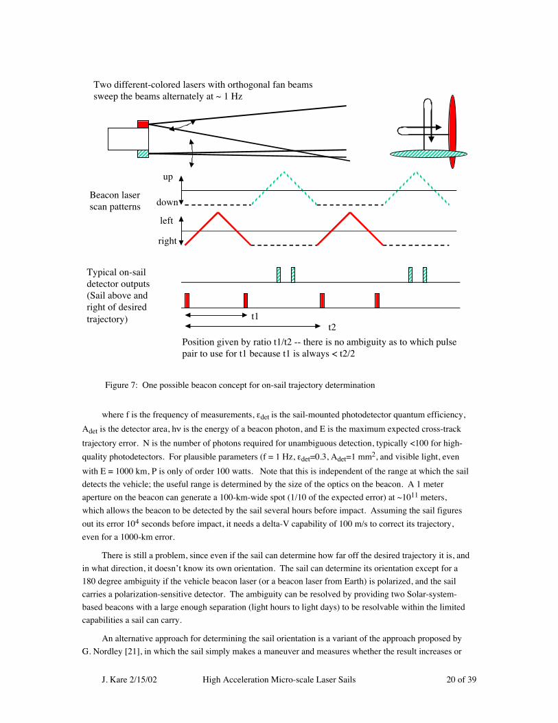
determine its trajectory error. Figure 7 shows one such concept. The required beacon power is given by:
Pbeacon = f εdet Adet N hν / π E2
∗ The relative velocity Vrel of the microsail approaching the vehicle is a system engineering choice, as
discussed below; the system operates most efficiently (maximum momentum delivered to vehicle) at the
highest feasible sail velocity, but this would give a varying impact velocity, and a very high velocity when
the vehicle is just starting out. For initial estimates, it is convenient to assume that the microsail launch
velocity will be adjusted to keep the relative velocity roughly constant, nominally Vrel = 0.02c = 6000
km/s.
J. Kare 2/15/02 High Acceleration Micro-scale Laser Sails 20 of 39
where f is the frequency of measurements, εdet is the sail-mounted photodetector quantum efficiency,
Adet is the detector area, hν is the energy of a beacon photon, and E is the maximum expected cross-track
trajectory error. N is the number of photons required for unambiguous detection, typically <100 for high-
quality photodetectors. For plausible parameters (f = 1 Hz, εdet=0.3, Adet=1 mm2, and visible light, even
with E = 1000 km, P is only of order 100 watts. Note that this is independent of the range at which the sail
detects the vehicle; the useful range is determined by the size of the optics on the beacon. A 1 meter
aperture on the beacon can generate a 100-km-wide spot (1/10 of the expected error) at ~1011 meters,
which allows the beacon to be detected by the sail several hours before impact. Assuming the sail figures
out its error 104 seconds before impact, it needs a delta-V capability of 100 m/s to correct its trajectory,
even for a 1000-km error.
There is still a problem, since even if the sail can determine how far off the desired trajectory it is, and
in what direction, it doesn’t know its own orientation. The sail can determine its orientation except for a
180 degree ambiguity if the vehicle beacon laser (or a beacon laser from Earth) is polarized, and the sail
carries a polarization-sensitive detector. The ambiguity can be resolved by providing two Solar-system-
based beacons with a large enough separation (light hours to light days) to be resolvable within the limited
capabilities a sail can carry.
An alternative approach for determining the sail orientation is a variant of the approach proposed by
G. Nordley [21], in which the sail simply makes a maneuver and measures whether the result increases or
Figure 7: One possible beacon concept for on-sail trajectory determination
up
down
left
right
Beacon laserscan patterns
Typical on-saildetector outputs(Sail above andright of desiredtrajectory) t1
t2
Position given by ratio t1/t2 -- there is no ambiguity as to which pulsepair to use for t1 because t1 is always < t2/2
Two different-colored lasers with orthogonal fan beamssweep the beams alternately at ~ 1 Hz

J. Kare 2/15/02 High Acceleration Micro-scale Laser Sails 21 of 39
decreases the trajectory error. This requires less sensor capability but may need more computing capability
on the sail.
Sail Terminal Maneuvering
Sail maneuvering can be accomplished with active micropropulsion at the expense of a significant
mass (e.g., several percent of initial sail mass for 500 m/s exhaust velocity). For high sail spin rates, it is
not necessary to supply propulsive exhaust velocity, just to drop mass from the sail rim with accurate (sub-
ms) timing. It is unfortunately not feasible to use either the launch laser or a vehicle-mounted laser for
terminal maneuvering; although the required velocities are small, the ranges involved are too great for a
reasonable combination of laser and aperture to generate a useful propulsive flux at the sail.
Radiation And Dust Damage
On-sail hardware is subject to damage by radiation or dust collisions while coasting at high velocity.
Microsails cannot carry shielding, so electronic components will need to be simple and extremely radiation-
hard. For a dust density of 0.5 x 10⁻⁶ particles/m3 and a coasting distance of order 1016 m (1 light year),
the sail will be struck by 5 x 10⁹ particles/m2, or an average spacing between impacts of ~14 microns. It
should be possible to design electronics to survive even this level of damage, by adjusting component size
and spacing (e.g., a 1 µm-square device would have <1% chance of being struck by a particle) and by using
extensive redundancy;. If not, this will drive SailBeam systems to shorter vehicle acceleration times and
higher laser powers, or to “dumb” sails without onboard hardware, or to finding some way of suppressing
particle damage.
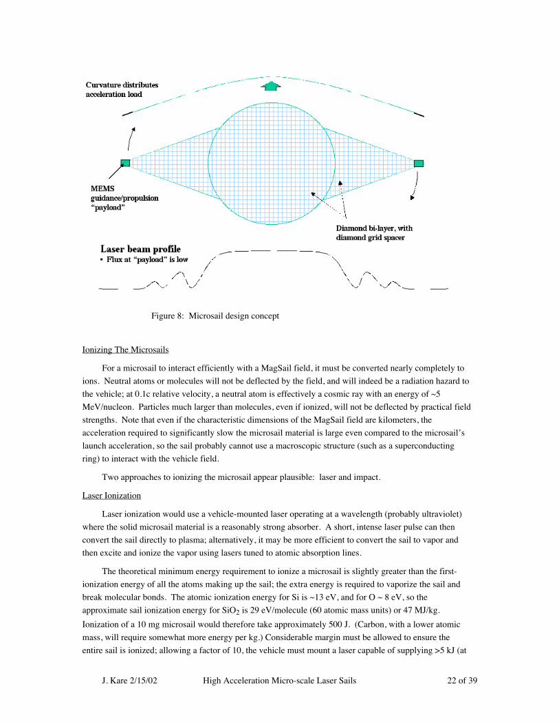
Sail Design Concept
A highly conceptual sail design is illustrated in Figure 8. The sail itself is two-layer diamond film
with vacuum spacing between layers; the spacing is maintained by a grid of raised diamond ridges or
bumps. The force on the first (laser-side) layer is substantially larger than the force on the second layer, so
by attaching additional mass to the second layer the two layers are held together under acceleration without
adhesive or other bonding.
The sail tows two “outriggers” which carry the terminal guidance sensors and mass-release
mechanisms for propulsion; the outriggers are single-layer diamond film. The combination of forces due to
spin and acceleration will result in the outriggers trailing the main sail, forcing the sail into a curve. If
necessary, the sail structure can incorporate open “beams” across the sail diameter perpendicular to the
outriggers to stiffen the sail against buckling, although fabrication techniques for such beams are currently
left as an exercise for the reader
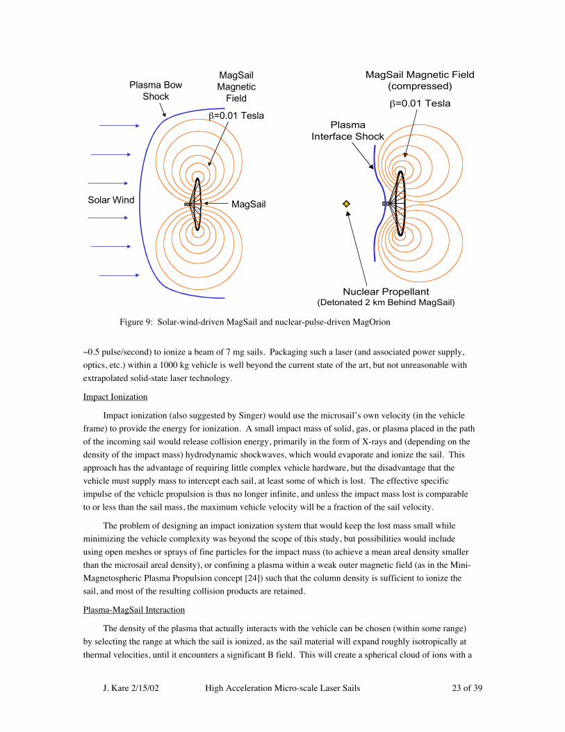
Sail-to-vehicle Coupling and MagSail Issues
The initial SailBeam concept assumed that microsail momentum could be coupled to a vehicle by
ionizing the sail and allowing the resulting plasma to reflect elastically from a vehicle-generated magnetic
field, in a fashion similar to the MagSail and MagOrion concepts [22] illlustrated in Figure 9. With the
assistance of Dr. Dana Andrews of Andrews Space & Technology (AST) we made a set of preliminary
calculations of both the energy required to ionize a sail, and the magnetic field and field coil characteristics
required to reflect a sail.
The bulk of these results were written up for publication as an IAF Conference Paper [23], and the
following sections are in large part copied directly from that paper.
J. Kare 2/15/02 High Acceleration Micro-scale Laser Sails 22 of 39
Ionizing The Microsails
For a microsail to interact efficiently with a MagSail field, it must be converted nearly completely to
ions. Neutral atoms or molecules will not be deflected by the field, and will indeed be a radiation hazard to
the vehicle; at 0.1c relative velocity, a neutral atom is effectively a cosmic ray with an energy of ~5
MeV/nucleon. Particles much larger than molecules, even if ionized, will not be deflected by practical field
strengths. Note that even if the characteristic dimensions of the MagSail field are kilometers, the
acceleration required to significantly slow the microsail material is large even compared to the microsail’s
launch acceleration, so the sail probably cannot use a macroscopic structure (such as a superconducting
ring) to interact with the vehicle field.
Two approaches to ionizing the microsail appear plausible: laser and impact.
Laser Ionization
Laser ionization would use a vehicle-mounted laser operating at a wavelength (probably ultraviolet)
where the solid microsail material is a reasonably strong absorber. A short, intense laser pulse can then
convert the sail directly to plasma; alternatively, it may be more efficient to convert the sail to vapor and
then excite and ionize the vapor using lasers tuned to atomic absorption lines.
The theoretical minimum energy requirement to ionize a microsail is slightly greater than the first-
ionization energy of all the atoms making up the sail; the extra energy is required to vaporize the sail and
break molecular bonds. The atomic ionization energy for Si is ~13 eV, and for O ~ 8 eV, so the
approximate sail ionization energy for SiO2 is 29 eV/molecule (60 atomic mass units) or 47 MJ/kg.
Ionization of a 10 mg microsail would therefore take approximately 500 J. (Carbon, with a lower atomic
mass, will require somewhat more energy per kg.) Considerable margin must be allowed to ensure the
entire sail is ionized; allowing a factor of 10, the vehicle must mount a laser capable of supplying >5 kJ (at
Figure 8: Microsail design concept
J. Kare 2/15/02 High Acceleration Micro-scale Laser Sails 23 of 39
~0.5 pulse/second) to ionize a beam of 7 mg sails. Packaging such a laser (and associated power supply,
optics, etc.) within a 1000 kg vehicle is well beyond the current state of the art, but not unreasonable with
extrapolated solid-state laser technology.
Impact Ionization
Impact ionization (also suggested by Singer) would use the microsail’s own velocity (in the vehicle
frame) to provide the energy for ionization. A small impact mass of solid, gas, or plasma placed in the path
of the incoming sail would release collision energy, primarily in the form of X-rays and (depending on the
density of the impact mass) hydrodynamic shockwaves, which would evaporate and ionize the sail. This
approach has the advantage of requiring little complex vehicle hardware, but the disadvantage that the
vehicle must supply mass to intercept each sail, at least some of which is lost. The effective specific
impulse of the vehicle propulsion is thus no longer infinite, and unless the impact mass lost is comparable
to or less than the sail mass, the maximum vehicle velocity will be a fraction of the sail velocity.
The problem of designing an impact ionization system that would keep the lost mass small while
minimizing the vehicle complexity was beyond the scope of this study, but possibilities would include
using open meshes or sprays of fine particles for the impact mass (to achieve a mean areal density smaller
than the microsail areal density), or confining a plasma within a weak outer magnetic field (as in the Mini-
Magnetospheric Plasma Propulsion concept [24]) such that the column density is sufficient to ionize the
sail, and most of the resulting collision products are retained.
Plasma-MagSail Interaction
The density of the plasma that actually interacts with the vehicle can be chosen (within some range)
by selecting the range at which the sail is ionized, as the sail material will expand roughly isotropically at
thermal velocities, until it encounters a significant B field. This will create a spherical cloud of ions with a
Solar Wind MagSail
Plasma BowShock
MagSailMagnetic
Field
β=0.01 TeslaPlasma
Interface Shock
MagSail Magnetic Field(compressed)
β=0.01 Tesla
Nuclear Propellant(Detonated 2 km Behind MagSail)
Figure 9: Solar-wind-driven MagSail and nuclear-pulse-driven MagOrion
J. Kare 2/15/02 High Acceleration Micro-scale Laser Sails 24 of 39
roughly gaussian density profile. Assuming an ion temperature of ~10 eV, the mean thermal velocity for Si
atoms will be Vth = (3kT/mSi)1/2 ~ 10 km/s. Thus, to distribute the sail over a ~100 m radius, the sail must
be ionized about 0.01 s before impact, at a range of ~60 km.
Analysis of the actual plasma-B field interaction is just beginning, and we are far from having a self-
consistent picture of the interaction. However, three different rough approximations yield similar results:
1. Dynamic pressure
Assuming the sail plasma, mass ms, behaves as a conductor which excludes magnetic fields, and is
comparable in size to the MagSail loop (i.e., to the scale length of the B field) the plasma as a whole will
experience a pressure somewhat less than, but of order, B2/2µ, where B is the field at the center of the loop
and µ=4π x 10-7 is the permittivity of vacuum. The plasma must decelerate over a distance comparable to
the loop radius r. The MagSail will therefore reflect the plasma provided
B2/2µ >> ms Vrel2 / π r3
For ms = 10-5 kg, Vrel=0.02c, and r~1 km, this gives B>>0.00045 T (4.5 gauss); for r~100 m,
B>>0.0145 T (145 gauss).
For a simple current loop, B = µI/2r, so
µI2 / 8 = ms Vrel2 / π r
2. Deflection
Assuming the sail ions behave as independent particles, they could be deflected by a B field oriented
perpendicular to the relative velocity vector. This is not how the MagSail would in fact be oriented, but an
approximate field strength can be estimated by requiring that the Larmor radius of the ions in such a field
be less than the field dimensions, i.e.
mion Vrel / qB << r
For singly-ionized Si ions (mass 28), this yields B>>.0017 T (17 gauss) for a 1 km loop and B>>.017
(170 gauss) for a 100 m loop; C ions (mass 12) would require ~2-fold lower fields. In this case, the loop
current I is independent of r, but the loop mass increases as r, so smaller, higher field loops are favored.
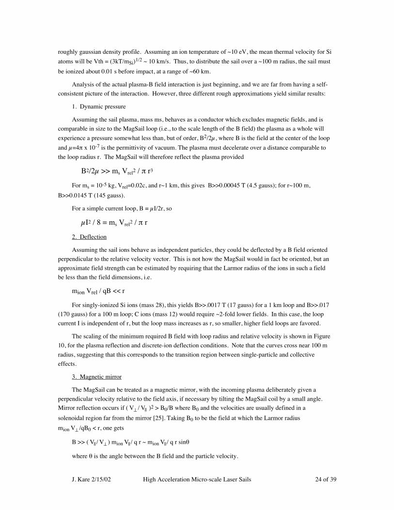
The scaling of the minimum required B field with loop radius and relative velocity is shown in Figure
10, for the plasma reflection and discrete-ion deflection conditions. Note that the curves cross near 100 m
radius, suggesting that this corresponds to the transition region between single-particle and collective
effects.
3. Magnetic mirror
The MagSail can be treated as a magnetic mirror, with the incoming plasma deliberately given a
perpendicular velocity relative to the field axis, if necessary by tilting the MagSail coil by a small angle.
Mirror reflection occurs if ( V⊥ / V|| )2 > B0/B where B0 and the velocities are usually defined in a
solenoidal region far from the mirror [25]. Taking B0 to be the field at which the Larmor radius
mion V⊥ /qB0 < r, one gets
B >> ( V||/ V⊥ ) mion V||/ q r ~ mion V||/ q r sinθ
where θ is the angle between the B field and the particle velocity.
J. Kare 2/15/02 High Acceleration Micro-scale Laser Sails 25 of 39
For small values of θ, this is simply equivalent to the deflection condition for the component of the B
field perpendicular to the incoming ion velocity. Tilting the MagSail by ~10 degrees yields B >> 0.01 T
(100 gauss) for a 1 km loop, or 0.1 T for a 100 m loop, for the nominal conditions, which can therefore be
considered an upper limit on the required field.
Current Loop Parameters
The loop material is characterized by the parameter j/ρ (current density/conductor density, in A/m2 /
kg/m3 = A-m/kg)
mloop = 2 π r I / (j/ρ)
A typical value used in MagSail calculations is 107 A-m/kg (considerably better than current
superconducting cables, which achieve ~106 A-m/kg).
A 1 km radius MagSail with a central field of ~0.01T (100 gauss) has a total current of 1.6 x 10⁷
amperes (16 MA) and therefore, with this j/ρ, a mass of ~10,000 kg, which is considerably larger than the
nominal vehicle mass of 2000 kg. A 100 m MagSail with a central field of 0.1T (1 kgauss) has the same
total current, but a mass of 1010 kg, compatible with the nominal vehicle mass. Additional payload mass
(as well as mass allowance for the ionization subsystem, etc.) can be achieved by scaling up the vehicle, at
the expense of needing a larger laser or longer acceleration time. Using a smaller, higher-field loop would
further reduce the loop mass, and also further reduce the range at which the microsails must be ionized
(assuming a plasma radius comparable to the loop radius is desire), but a 100 m loop is already a very small
target over interstellar distances, even with terminal guidance.
0.0001
0.0010
0.0100
0.1000
1.0000
10 100 1000 10000
Loop Radius, meters
Min
imum
B f
ield
, Tes
la.02c Reflection.1c Reflection.02c Deflection.1c Deflection
Figure 10: B field requirements for microsail coupling

J. Kare 2/15/02 High Acceleration Micro-scale Laser Sails 26 of 39
Momentum Pulse
The minimum MagSail loop size may also be limited by the amplitude and duration of the impulse
delivered by the microsail. Each microsail delivers an impulse of (2 ms Vrel) ~ 12 N-s per milligram to the
loop over a period of ~ 2 r/Vrel, and over a loop length of 2π r; the average force on a unit length of loop
during the interaction is thus ms Vrel2 / 2 π r2. For a 100 meter loop, the impulse is ~6 kN per meter for
~33 µs, which may be sufficient (especially over >108 pulses) to damage the loop, or at least constrain its
construction. For a 1 km loop, the force is a much gentler 60 N per meter, applied for ~330 µs.
Energy Pulse
The inductance of a single current loop is L=cµ02πr, where c is a constant of order 1 that depends on
the conductor dimensions. The stored energy is simply Emag = 1/2 LI2. For the nominal 16 MA loop
current estimated above, Emag ~ 109r J. The incident sail has a kinetic energy of 1/2 ms Vrel2, which is a
fraction of a GJ for the baseline case. Thus, provided r is larger than a few meters, the temporary
conversion of the sail’s kinetic energy into magnetic field energy will not significantly change the stored
energy; this is an advantage of a MagSail-type large loop over a compact, high-field coil.
However, rapidly changing currents will produce dissipation (e.g., due to eddy currents in normal
conductors surrounding the superconducting cable material) and even small amounts of dissipation will
dominate the heat load on the MagSail loop. This may limit the minimum usable loop diameter, and
dissipation will need to be determined (by modeling or experiment) for actual superconducting cable.
MagSail Braking
A MagSail field will also deflect ionized material in the interstellar medium (ISM), and will therefore
produce drag when active. The magnitude of this drag can be estimated by treating the MagSail as a
dipole, which will form a magnetosphere whose size is set by equilibrium between the dynamic pressure of
the ISM and the magnetic field pressure. The drag force is calculated to be:
Fdrag = 1.175 π (Ni mi µ1/2 I r2 V2)2/3
where Ni and mi are the number density and mass of ISM ions, and V is the vehicle velocity through
the ISM, nominally 0.1c = 3 x 10⁷ m/s.
For the baseline 100 meter loop, and with an assumed density of the ISM of 105 ions/m3, the drag is
33.6 N. This is larger than the mean thrust from the microsail beam for a ~1000-kg vehicle (which receives
an 84 N-s impulse approximately every [2 s * Vrel/V] = 10 seconds), so either the thrust must be increased
or drag suppressed. Fortunately, the drag can be suppressed using a second current loop to produce a
dipole field which cancels the MagSail field at large distances, but does not greatly affect the central field.
An efficient geometry for this would use a second coplanar loop with a larger radius and smaller current;
since the dipole field is proportional to Ir2, the total mass (proportional to Ir) of the second loop can be
smaller than that of the main loop by the ratio of the radii. The drag of such a double loop will be
approximately the dynamic pressure of the ISM times the area of the larger loop; for a 1 km outer loop this
is only 0.24 N. Unfortunately, the actual drag will be larger, since the fields do not cancel accurately until
well outside the radius of the outer loop, but even a several-times-higher drag is acceptable.
Once acceleration is complete, the MagSail field can be turned off (or at least reduced) for interstellar
cruise.
J. Kare 2/15/02 High Acceleration Micro-scale Laser Sails 27 of 39
However, MagSail drag can be used to advantage in slowing an interstellar probe as it approaches its
destination. The optimum MagSail configuration for braking involves a much larger-diameter current loop
and lower-strength field than for propulsion -- ideally, a centerline field comparable to the ISM dynamic
pressure at the current velocity. A separate current loop can be used, but given the high cost of getting any
mass up to interstellar velocities, it may be worthwhile to engineer a multiturn current loop that can
unwound, unfolded, or otherwise redeployed to form the deceleration loop.
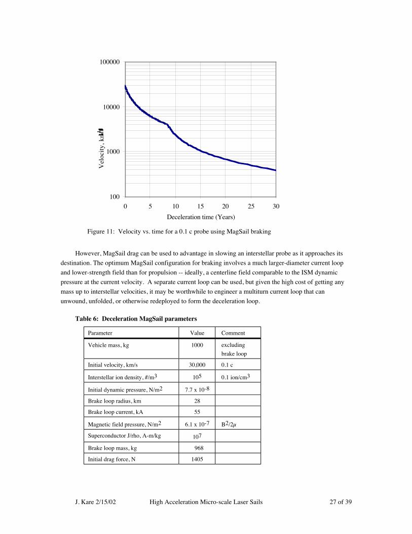
Table 6: Deceleration MagSail parameters
Parameter Value Comment
Vehicle mass, kg 1000 excluding
brake loop
Initial velocity, km/s 30,000 0.1 c
Interstellar ion density, #/m3 105 0.1 ion/cm3
Initial dynamic pressure, N/m2 7.7 x 10⁻⁸
Brake loop radius, km 28
Brake loop current, kA 55
Magnetic field pressure, N/m2 6.1 x 10⁻⁷ B2/2µ
Superconductor J/rho, A-m/kg 107
Brake loop mass, kg 968
Initial drag force, N 1405
100
1000
10000
100000
0 5 10 15 20 25 30
Deceleration time (Years)
Vel
ocit
y, k
m/s
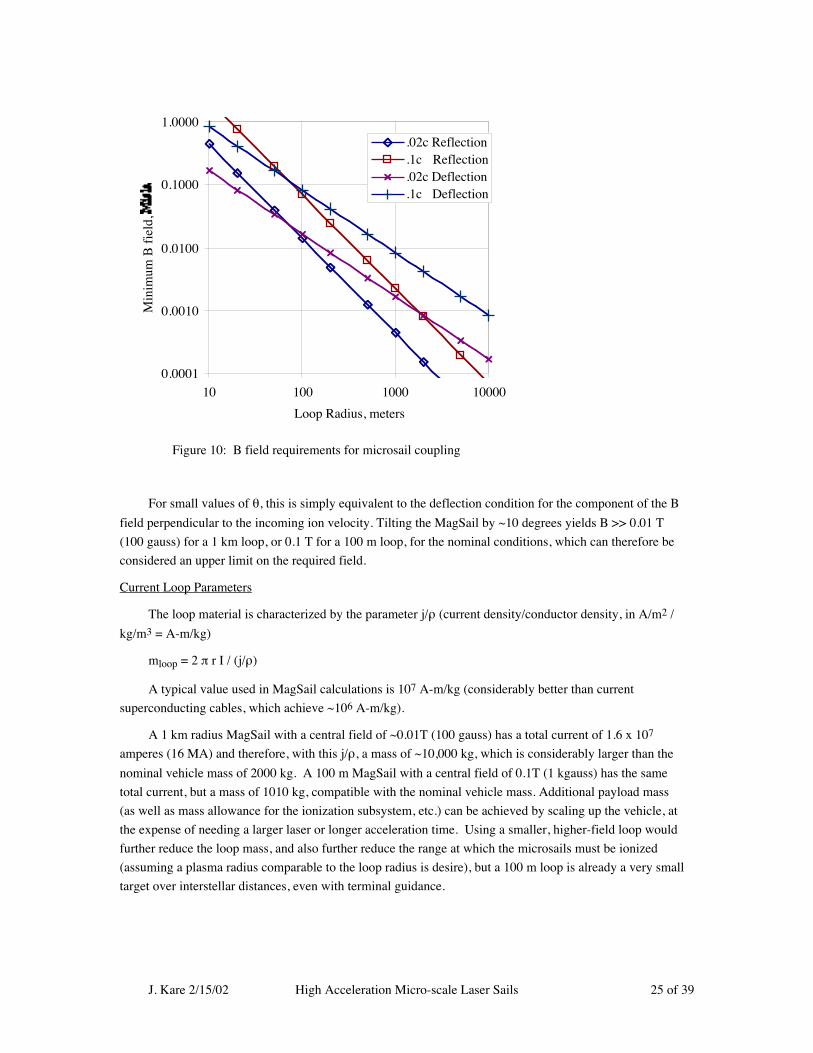
Figure 11: Velocity vs. time for a 0.1 c probe using MagSail braking

J. Kare 2/15/02 High Acceleration Micro-scale Laser Sails 28 of 39
Typical parameters for a deceleration loop (sized for a 1:1 ratio of loop conductor mass to rest-of-
vehicle mass) are shown in Table 6, and the corresponding velocity-vs.time and velocity-vs. range curves
are shown in Figure 11. The break in the curves in Figure 11 marks a redeployment of the deceleration loop
to double its initial diameter for improved low-velocity braking.
Below ~500 km/s, further braking can be done against the stellar wind of the target star, or via other
propulsion technologies such as nuclear-electric, to bring a probe to rest in the target system.
Note that the drag brake is, to first order, scale invariant: both the drag force and the drag-brake
current loop mass are proportional to the product of the loop diameter and loop current, so the same
deceleration can be achieved for any vehicle mass, provided the plasma behavior of the ISM is unchanged.
Task 2: System Parameters and Scaling
Sail Velocity vs. Vehicle Velocity
One factor which strongly affects the overall system design is the ratio of sail velocity to vehicle
velocity. Clearly the vehicle velocity vv can never equal the sail velocity vs, since the sail would never
overtake the vehicle. As the vehicle velocity approaches the sail velocity, the sail beam is effectively
Doppler shifted: the interval between arriving sails increases as 1/( vs - vv). Also, each sail transfers at
most momentum 2 ms(vs - vv) to the vehicle, despite acquiring msailvsail momentum from the laser. The
“momentum efficiency” of the sail is therefore 2(vs - vv)/ vs.
The vehicle velocity can be calculated as a function of the ratio of the mass of sails that have hit the
vehicle to the vehicle mass. For a fixed sail velocity, the resulting relationship is essentially a modified
rocket equation:
vv / vs = 1 - e-2 ms/mv
Assuming the launcher cuts off after launching a given mass of sails, this gives the final vehicle
0.0
0.2
0.4
0.6
0.8
1.0
1.2
1.4
1.6
0 1 2 3
Total sail mass/vehicle mass
0.0
0.2
0.4
0.6
0.8
1.0
1.2
1.4
1.6
Veh
icle
fin
al v
eloc
ity/s
ail
velo
city E
nergy efficiency vs. single sail
Figure 12: Sail mass vs. vehicle velocity and system efficiency

J. Kare 2/15/02 High Acceleration Micro-scale Laser Sails 29 of 39
velocity. One can also calculate an efficiency: how much energy the laser must expend to launch a
particular mass of sails, vs. the laser energy required to directly accelerate the vehicle mass (presumably in
the form of a large laser sail) to the same resulting final velocity.
The results of these calculations are plotted in Figure 12. As a practical matter (assuming any of this is
practical) there is little advantage in going above a sail-to-vehicle mass ratio of 1, which provides a vehicle
velocity of 0.865 times the sail velocity, or, equivalently, requires a sail velocity of 1.156 times the vehicle
mission velocity. (In various calculations, we have rounded this up to a sail velocity of 1.2 times the
mission velocity). However, it may be desirable to move in the opposite direction, and use fewer, higher
velocity sails to increase the energy efficiency of the system, if the cost (in optics, particularly) of
increasing the sail launch velocity is not too high.
Using a constant sail velocity, however, means that early in a vehicle’s flight, sails strike it at very
high velocity. The engineering of the sail-to-vehicle coupling may make fixing, or at least limiting the sail
impact velocity desirable. For a simple fixed overtaking velocity, the vehicle velocity can easily be shown
to be just vv = 2 (vs - vv) ms/ vv -- i.e., every unit mass of sails contributes the same amount of momentum
to the vehicle. However, the rate at which sails are launched will vary, since the time to accelerate each sail
will be lower when the vehicle (and sail) velocities are lower, so the vehicle’s rate of acceleration will
decrease as its velocity increases. Overall, the efficiency of a system with a fixed sail impact velocity will
always be lower than that of a system that launches all sails at maximum velocity.
Point System Designs For a SailBeam Launcher
Given the sail and other design constraints above, we built a simple spreadsheed model to size a
sailbeam launcher. Table 7 shows system parameters for several possible sail designs, assuming a constant
sail velocity.
The maximum sail velocity is determined by the fact that the sail and vehicle masses are equal, plus
the assumption that the sail velocity is constant: Vsail = 1.2 Vmission. As discussed above, if Vsail is
varied to give, for example, a constant sail impact velocity at the vehicle, the system parameters --
especially total sail mass and number of sails -- could change substantially.
Note that although silicon sails require a much larger telescope than the other sail alternatives, the
telescope is operating at a 4X longer wavelength, and is therefore easier to build, than the telescopes for
other sails.
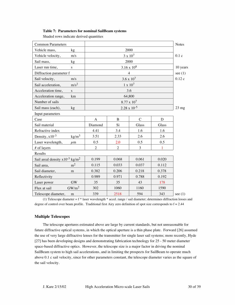
J. Kare 2/15/02 High Acceleration Micro-scale Laser Sails 30 of 39
Table 7: Parameters for nominal SailBeam systemsShaded rows indicate derived quantities
Common Parameters Notes
Vehicle mass, kg 2000
Vehicle velocity, m/s 3 x 10⁷ 0.1 c
Sail mass, kg 2000
Laser run time, s 3.16 x 10⁸ 10 years
Diffraction parameter f 4 see (1)
Sail velocity, m/s 3.6 x 10⁷ 0.12 c
Sail acceleration, m/s2 1 x 10⁷
Acceleration time, s 3.6
Acceleration range, km 64,800
Number of sails 8.77 x 10⁷
Sail mass (each), kg 2.28 x 10⁻⁵ 23 mg
Input parameters
Case A B C D
Sail material Diamond Si Glass Glass
Refractive index 4.41 3.4 1.6 1.6
Density, x10-3 kg/m3 3.51 2.33 2.6 2.6
Laser wavelength, µm 0.5 2.0 0.5 0.5
# of layers 2 2 3 1
Results
Sail areal density x10-3 kg/m2 0.199 0.068 0.061 0.020
Sail area, m2 0.115 0.033 0.037 0.112
Sail diameter, m 0.382 0.206 0.218 0.378
Reflectivity 0.989 0.971 0.788 0.192
Laser power GW 35 35 43 178
Flux at sail GW/m2 302 1060 1160 1590
Telescope diameter, m 339 2518 594 343 see (1)(1) Telescope diameter = f * laser wavelength * accel. range / sail diameter; determines diffraction losses and
degree of control over beam profile. Traditional first Airy zero definition of spot size corresponds to f = 2.44
Multiple Telescopes
The telescope apertures estimated above are large by current standards, but not unreasonable for
future diffractive optical systems, in which the optical aperture is a thin phase plate. Forward [26] assumed
the use of very large diffractive lenses for the transmitter for single laser sail systems; more recently, Hyde
[27] has been developing designs and demonstrating fabrication technology for 25 - 50 meter diameter
space-based diffractive optics. However, the telescope size is a major factor in driving the nominal
SailBeam system to high sail accelerations, and in limiting the prospects for SailBeam to operate much
above 0.1 c sail velocity, since for other parameters constant, the telescope diameter varies as the square of
the sail velocity.
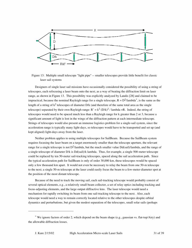
J. Kare 2/15/02 High Acceleration Micro-scale Laser Sails 31 of 39
Designers of single laser sail missions have occasionally considered the possibility of using a string of
telescopes, each refocusing a laser beam onto the next, as a way of beating the diffraction limit on laser
range, as shown in Figure 13. This possibility was explicitly analyzed by Landis [28] and claimed to be
impractical, because the nominal Rayleigh range for a single telescope, R = D2/lambda*, is the same as the
length of a string of k2 telescopes of diameter D/k (and therefore of the same total area as the single
telescope) separated by their own Rayleigh range: R’ = k2 (D/k)2 / lambda =R. Indeed, the string of
telescopes would need to be spaced much less than a Rayleigh range for k greater than 2 or 3, because a
significant amount of light is lost in the wings of the diffraction pattern at each intermediate telescope.
Strings of telescopes would also present an immense logistics problem for a single-sail system, since the
acceleration range is typically many light-days, so telescopes would have to be transported and set up (and
kept aligned) light-days away from the laser.
Neither problem applies to using multiple telescopes for SailBeam. Because the SailBeam system
requires focusing the laser beam on a target enormously smaller than the telescope aperture, the relevant
range for a single telescope is not D2/lambda, but the much smaller value Dd(sail)/lambda, and the range of
a single telescope of diameter D/k is Dd(sail)/k lambda. Thus, for example, a single 500-meter telescope
could be replaced by ten 50-meter sail-tracking telescopes, spaced along the sail acceleration path. Since
the typical acceleration path for SailBeam is only of order 30,000 km, these telescopes would be spaced
only a few thousand km apart. It would not even be necessary to relay the beam from one 50-m telescope
to the next; a single 50-m telescope at the laser could easily focus the beam to a few-meter-diameter spot at
the position of the most distant telescope.
Because of the need to track the moving sail, each sail-tracking telescope would probably consist of
several optical elements, e.g., a relatively small beam collector, a set of relay optics including tracking and
focus-adjusting elements, and the large output diffractive lens. The laser telescope would need a
mechanism for rapidly switching its beam from one sail-tracking telescope to the next. Also, each
telescope would need a way to remain correctly located relative to the other telescopes despite orbital
dynamics and perturbations, but given the modest separation of the telescopes, small solar sails (perhaps
* We ignore factors of order 2, which depend on the beam shape (e.g., gaussian vs. flat-top/Airy) and
the allowable diffraction losses.
Figure 13: Multiple small telescope "light pipe" -- smaller telescopes provide little benefit for classic
laser sail systems
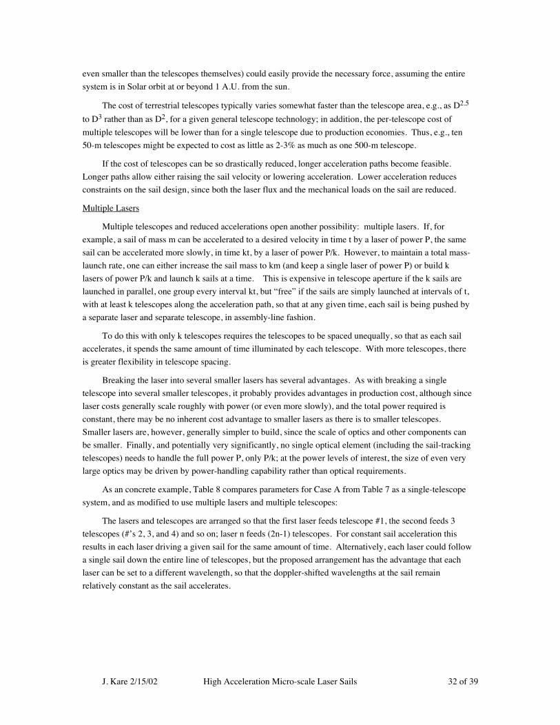
J. Kare 2/15/02 High Acceleration Micro-scale Laser Sails 32 of 39
even smaller than the telescopes themselves) could easily provide the necessary force, assuming the entire
system is in Solar orbit at or beyond 1 A.U. from the sun.
The cost of terrestrial telescopes typically varies somewhat faster than the telescope area, e.g., as D2.5
to D3 rather than as D2, for a given general telescope technology; in addition, the per-telescope cost of
multiple telescopes will be lower than for a single telescope due to production economies. Thus, e.g., ten
50-m telescopes might be expected to cost as little as 2-3% as much as one 500-m telescope.
If the cost of telescopes can be so drastically reduced, longer acceleration paths become feasible.
Longer paths allow either raising the sail velocity or lowering acceleration. Lower acceleration reduces
constraints on the sail design, since both the laser flux and the mechanical loads on the sail are reduced.
Multiple Lasers
Multiple telescopes and reduced accelerations open another possibility: multiple lasers. If, for
example, a sail of mass m can be accelerated to a desired velocity in time t by a laser of power P, the same
sail can be accelerated more slowly, in time kt, by a laser of power P/k. However, to maintain a total mass-
launch rate, one can either increase the sail mass to km (and keep a single laser of power P) or build k
lasers of power P/k and launch k sails at a time. This is expensive in telescope aperture if the k sails are
launched in parallel, one group every interval kt, but “free” if the sails are simply launched at intervals of t,
with at least k telescopes along the acceleration path, so that at any given time, each sail is being pushed by
a separate laser and separate telescope, in assembly-line fashion.
To do this with only k telescopes requires the telescopes to be spaced unequally, so that as each sail
accelerates, it spends the same amount of time illuminated by each telescope. With more telescopes, there
is greater flexibility in telescope spacing.
Breaking the laser into several smaller lasers has several advantages. As with breaking a single
telescope into several smaller telescopes, it probably provides advantages in production cost, although since
laser costs generally scale roughly with power (or even more slowly), and the total power required is
constant, there may be no inherent cost advantage to smaller lasers as there is to smaller telescopes.
Smaller lasers are, however, generally simpler to build, since the scale of optics and other components can
be smaller. Finally, and potentially very significantly, no single optical element (including the sail-tracking
telescopes) needs to handle the full power P, only P/k; at the power levels of interest, the size of even very
large optics may be driven by power-handling capability rather than optical requirements.
As an concrete example, Table 8 compares parameters for Case A from Table 7 as a single-telescope
system, and as modified to use multiple lasers and multiple telescopes:
The lasers and telescopes are arranged so that the first laser feeds telescope #1, the second feeds 3
telescopes (#’s 2, 3, and 4) and so on; laser n feeds (2n-1) telescopes. For constant sail acceleration this
results in each laser driving a given sail for the same amount of time. Alternatively, each laser could follow
a single sail down the entire line of telescopes, but the proposed arrangement has the advantage that each
laser can be set to a different wavelength, so that the doppler-shifted wavelengths at the sail remain
relatively constant as the sail accelerates.
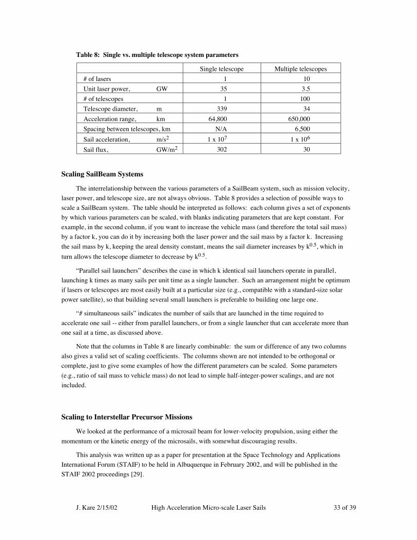
J. Kare 2/15/02 High Acceleration Micro-scale Laser Sails 33 of 39
Table 8: Single vs. multiple telescope system parameters
Single telescope Multiple telescopes
# of lasers 1 10
Unit laser power, GW 35 3.5
# of telescopes 1 100
Telescope diameter, m 339 34
Acceleration range, km 64,800 650,000
Spacing between telescopes, km N/A 6,500
Sail acceleration, m/s2 1 x 10⁷ 1 x 10⁶
Sail flux, GW/m2 302 30
Scaling SailBeam Systems
The interrelationship between the various parameters of a SailBeam system, such as mission velocity,
laser power, and telescope size, are not always obvious. Table 8 provides a selection of possible ways to
scale a SailBeam system. The table should be interpreted as follows: each column gives a set of exponents
by which various parameters can be scaled, with blanks indicating parameters that are kept constant. For
example, in the second column, if you want to increase the vehicle mass (and therefore the total sail mass)
by a factor k, you can do it by increasing both the laser power and the sail mass by a factor k. Increasing
the sail mass by k, keeping the areal density constant, means the sail diameter increases by k0.5, which in
turn allows the telescope diameter to decrease by k0.5.
“Parallel sail launchers” describes the case in which k identical sail launchers operate in parallel,
launching k times as many sails per unit time as a single launcher. Such an arrangement might be optimum
if lasers or telescopes are most easily built at a particular size (e.g., compatible with a standard-size solar
power satellite), so that building several small launchers is preferable to building one large one.
“# simultaneous sails” indicates the number of sails that are launched in the time required to
accelerate one sail -- either from parallel launchers, or from a single launcher that can accelerate more than
one sail at a time, as discussed above.
Note that the columns in Table 8 are linearly combinable: the sum or difference of any two columns
also gives a valid set of scaling coefficients. The columns shown are not intended to be orthogonal or
complete, just to give some examples of how the different parameters can be scaled. Some parameters
(e.g., ratio of sail mass to vehicle mass) do not lead to simple half-integer-power scalings, and are not
included.
Scaling to Interstellar Precursor Missions
We looked at the performance of a microsail beam for lower-velocity propulsion, using either the
momentum or the kinetic energy of the microsails, with somewhat discouraging results.
This analysis was written up as a paper for presentation at the Space Technology and Applications
International Forum (STAIF) to be held in Albuquerque in February 2002, and will be published in the
STAIF 2002 proceedings [29].

J. Kare 2/15/02 High Acceleration Micro-scale Laser Sails 34 of 39
The fundamental problem is one of energy efficiency. The energy efficiency of accelerating laser
sails (of any size) is, in a non-relativistic approximation, 2v/c, so for low sail velocities, most of the laser
energy is wasted -- carried away by the reflected photons. Accelerating microsails to high velocity and
then using them as a momentum beam to accelerate a low-velocity vehicle is also energy-inefficient, since
most of the sail kinetic energy is wasted.
Using high-velocity sails to carry energy to a low-velocity vehicle is reasonably efficient, but likely to
be hard to implement in a useful architecture. Efficiently capturing the kinetic energy of a sail arriving at
~0.1 c relative velocity, and converting the energy to a useful form (i.e., to kinetic energy of a lower-
velocity rocket exhaust) is one problem. Another, possibly larger, is that the microsail launcher -- laser and
transmitter optics -- scale rapidly with the sail velocity, so that a system capable of launching microsails at
high velocity will necessarily be very large.
For interstellar missions, low efficiency and large systems are acceptable, because alternative
propulsion techniques require even larger systems, if they work at all. For interstellar precursor missions
(and Solar System exploration) at velocities below ~3000 km/s (1% of c) much less capital-intensive
alternatives are feasible, including both self-contained systems such as nuclear-electric propulsion and
beamed-energy or beamed-momentum systems.
Fortunately, there is a strong synergy between direct laser beamed-energy systems and eventual
SailBeam systems: both use the same technologies of large lasers (albeit with different constraints on
wavelength, etc.) and large diffractive optics. Laser beamed-energy systems are strong contenders for
Vary systemparameter
La
ser
run
tim
e
La
ser
po
we
r
La
ser p
ow
er a
nd
sa
il flu
x
La
ser p
ow
er; fix
tele
scop
e
size
Pa
ralle
l sa
il la
un
che
rs
La
ser
run
tim
e
La
ser
po
we
r
La
ser
run
tim
e
Sa
il a
ccele
ratio
n
Mu
ltiple
te
lesco
pe
s
Pa
ralle
l sa
il la
un
che
rs
Mu
ltiple
lase
rs +
tele
scop
es
Sa
il A
rea
l d
en
sity
Sa
il A
rea
l d
en
sity a
nd
flu
x
La
ser
wa
vele
ng
th
Sail total mass 1 1 1 1 1
Sail velocity 1 1
Laser run time 1 1 1
Laser power 1 1 1 1 - 1 - 1 - 1
Laser wavelength 1
# of lasers 1 1 1
Sail acceleration 1 - 1 1 1 - 1 - 1 - 1
Flux at sail 1 - 1 1 1 - 1 1
Sail accel time - 1 1 1 - 1 1 1 1
Sail accel. range - 1 1 2 1 - 1 1 1 1
Sail launch rate 1 - 1 1 - 1 1 - 1
# simultaneous sails 1 1 1
Sail mass ea. 1 2 1 - 1 - 1 - 1 1 1
Sail diameter 0 .5 1 0.5 - 0 . 5 - 0 . 5 - 0 . 5 - 0 . 5
Sail areal density 1 1 1
Telescope diam. - 0 . 5 - 1 1 .5 1 0 .5 - 0 . 5 - 1 0 .5 - 1 1 0.5 2
# of telescopes 1 1 1 2
Vehicle size + Mission V +
Table 9: Scaling relationships among SailBeam system parameters

J. Kare 2/15/02 High Acceleration Micro-scale Laser Sails 35 of 39
interstellar precursor and solar-system exploration mission propulsion, [30] provided that appropriate high-
power laser technology is developed.
Task 3: Technology Roadmap
Technology Roadmap
Figure 14 shows a very rough technology and mission roadmap for SailBeam. This map serves
mainly to indicate the degree to which many different technologies, each worth developing in its own right,
can enable a relatively near-term interstellar mission capability.
The development of large space optics is already a priority for both NASA and military space users.
Within the next decade, the Next Generation Space Telescope should mark the first large step beyond the
Hubble Space Telescope, and the first space telescope comparable in diameter to the largest terrestrial
telescopes. However, much larger space telescopes are already being designed, many using various so-
called gossamer spacecraft technologies -- membrane mirrors, and flexible active structures. Diffractive
optics (flat, thin zone plates or low-order Fresnel lenses) are ideal for narrowband laser optical systems, and
already appear to be feasible at the 25 meter scale, so there seems little doubt that the actual main apertures
needed for SailBeam will be available by the 2020’s or 2030’s. However, development of a complete
SailBeam optical system, including the active optics required to track microsails over a large focal range at
0.1 c or higher, will require at least one generation of additional development more-or-less unique to
SailBeam.
2010 2020 2030 2040 2050
NGST (6 m)
SBL (~1 MWchemical).
SPS demokW-scale
Microsaildevelopment
MagSailcable deve.l
Eyeglass (25 mdiffractive)
NNGST (25 m?)
SPS prototypeMW-scale
Magsail/M2P2 demo
TOPS Large interferometers
Solar sail demo
50 m aperturelaser transmittersand relay optics
1st operationalSPS - GW-scale
SPS productionmany GW/year
SailBeamsystem demo
Microsail coupling demo
SailBeamlauncher
integration,test launches
Vehicle prototype testing (20 yr)
2002
Optics
Lasers
MagSail
SailBeam
Solar PowerSatellites
Solar Sails
Dedicated SPS’sfor SailBeam
PrototypeSailBeam optics(3 x 50 m)
SailBeam opticsproduction(100 x 50 m)
MW-class spacepower beamingdemo
100 MW-classpropulsion laserdemo
Solar sail station-keeping demo
Solar sail station-keeping
PrototypeSailBeam laser(1 GW)
SailBeam laserproduction(10 x 5 GW)
Microsail acceleration demo
Interstellarprobe launch
Laser thermalground tests
Laser electric demo (~1 kW)
Operational MWlaser propulsionin cislunar space
Operationallaser propulsion;Laser
Propulsion
Laser thermalspace demo (~1 MW) Mars missions,
ISP missions
Microsail guidance demo
Figure 14: Nominal technology and mission roadmap for interstellar mission launch in 2050

J. Kare 2/15/02 High Acceleration Micro-scale Laser Sails 36 of 39
Solar sails are listed as the preferred technology for maintaining all the components of a microsail
launcher in position over many years. For a SailBeam launcher in Solar orbit, only a very small
acceleration (microns/s2) is required to keep lasers and telescopes separated by tens or hundreds of
thousands of km in the correct relative position against gravitational gradients., but to do so with
conventional propulsion would be extremely costly. In addition the laser beams themselves will exert a
significant force on all the optics in the system.
High average power lasers are the obvious “long pole” for SailBeam, and it is critically important
that efficient gigawatt-class lasers be developed if SailBeam is to be practical. Unfortunately, except for
military applications, there have been few uses for such large lasers. Lasers are in some respects appealing
for transmitting energy from satellite solar power stations, but have lower efficiency than microwave
sources (although potentially by less than a factor of 2) and are a source of social and safety concerns if
aimed at Earth.
We propose that, beyond the current generation of space-based laser weapons, large lasers be
developed primarily as a means of transmitting power in space, to enable high-performance laser-thermal
or laser-electric propulsion.
Looking at specific laser technologies and applications was beyond the scope of this study, but
the obvious candidates for efficient, very-high-power lasers are phased arrays of laser diodes (up to 50%
efficient at near-infrared wavelengths) and free electron lasers. Current costs for large laser systems are of
order $1000/watt ($35 trillion for the baseline SailBeam system) but either technology could potentially
drop the cost of the lasers themselves to well under $10/watt, and thus the system cost to a large but not
unreasonable $350 billion). It is worth noting that lasers have existed for less than 40 years, and are still
evolving new types and increasing in performance quite rapidly, so 40 more years should see significant
progress in lasers.
Solar power satellites are of course the logical power source for SailBeam, as well as the logical
driver for the type of large-scale space industrial capability that would be needed to build the SailBeam
launcher. Laser propulsion has already been touched on as the logical driver for lasers, and is also the
logical driver for system integration and operations similar to what SailBeam will require. Laser
propulsion is also very well suited to launching of interstellar precursor missions, and to lowering the cost
of activities in the inner solar system by providing readily available power and high-specific-impulse
propulsion anywhere, at any time.
Finally, MagSails and their relatives are an interesting space technology in their own right, but
probably represent a relatively small investment, which, if not developed by other programs, could be
developed relatively quickly specifically for SailBeam.
Near-Term Experiments
The most urgent, and also fortunately most tractable, aspect of technology development for SailBeam
is the development and demonstration of high-flux microsails themselves.
Because of the limited understanding of thin-film behavior (absorption, mechanical properties, failure
modes, etc.) under the conditions of sustained high-flux illumination needed for microsail acceleration, it
seems desirable to begin with testing that approximates these conditions, as opposed to, e.g., starting with
absorption measurements at low flux.

J. Kare 2/15/02 High Acceleration Micro-scale Laser Sails 37 of 39
There are a number of laser facilities in the U.S. with pulsed lasers capable of 100 J or more in the
visible or near-IR -- primarily Nd:Glass lasers developed for fusion research. Unfortunately, most of these
lasers are set up to produce short pulses, typically a few microseconds or shorter, at high peak power.
We have identified one facility so far which can produce pulses well-suited to testing microsail
materials and designs. LHMEL, the Laser Hardened Material Evaluation Laboratory, is a facility operated
by Anteon Corp. for the Air Force Research Laboratory. Among other systems, LHMEL has a large
flashlamp-pumped laser system that can produce up to 5 kJ in a 0.5 millisecond pulse or 10 kJ in a 5
millisecond pulse. The laser system has two independent beam trains and flexible control over flashlamp
timing, so that various other pulse formats are possible, and both the spatial and temporal properties of the
beam are well-suited to microsail testing.
There are several possible next steps after static testing of microsail materials. Depending on the test
results, development of improved materials and/or fabrication processes may be the highest priority. A
very satisfying next step would be a demonstration of actual free-flying microsails in a laboratory. Free-
flight tests lasting even a few milliseconds would confirm the feasibility of spin-stabilizing sails and of
keeping a laser focused on a fast-moving sail. Existing lasers could potentially accelerate mm-sized sails to
several 10’s of km/s within a reasonable laboratory distance, which would make the demonstration setup
useful as a source of hypervelocity projectiles for other research.
Unfortunately, an in-space demonstration of high-acceleration sails will require a fairly large space-
based laser, or a ground-based laser plus space relay optics. We leave consideration of those and
subsequent experiments for future work.
Conclusions
After investigating several of the relevant pieces of physics and technology, we are pleasantly
surprised that SailBeam continues to look very promising as a way to send probes -- and perhaps eventually
people -- to nearby stars. The biggest concerns -- the ability of microsails to withstand both very high
fluxes and large mechanical stresses from high acceleration -- are greatly alleviated by the multiple
telescope approach invented (or perhaps reinvented) in the course of this effort; multiple telescopes allow a
SailBeam system to be built with at least an order of magnitude lower fluxes and accelerations, compared
to a single-telescope system with similar optics technology. Another major concern -- that microsails could
not be effectively used to push a large vehicle -- proved almost certainly unfounded.
The fact that SailBeam-launched probes can plausibly be made to stop at their destinations, rather
than zooming by at thousands of km/s, makes the overall value of SailBeam enormously greater.
There are still enormous challenges at very basic levels that SailBeam must meet to have a chance of
actually working. Thin films with at least somewhat lower absorption are needed, and much lower
absorption levels are very desirable. The possibility that interstellar dust will convert smart, self-guiding
microsails into very thin dishrags before they reach their intended target is worrisome. However, none of
these problems seem comparable to the challenges of, for example, making and storing large quantities of
antimatter, or building multi-thousand kilometer telescopes, and they are clearly susceptible to brute-force
solutions (lower sail accelerations, higher vehicle accelerations) if we are willing to pay the cost in
hardware.
J. Kare 2/15/02 High Acceleration Micro-scale Laser Sails 38 of 39
Finally, the failure of SailBeam to make a good propulsion system for low-velocity (by interstellar
standards) missions proved to have offsetting benefits, since it highlighted the strong synergy between
SailBeam and other laser-based propulsion systems that are very promising for exactly those missions. As
even a very preliminary roadmap shows, there is a clear set of mutually-reinforcing technologies that may
well be able to take us to the stars.
References
1. Myrabo, Leik N., "Laser Sail Technology Demonstration", Final Technical Report, Dept. Mech. Eng.,
Rensselaer Poly. Inst., 2000.
2. Benford, James, et. al., “Microwave Beam-Driven Sail Flight Experiments,” Space Technology and
Applications International Forum-2001, M. S. El-Genk, ed., AIP Conf. Proc. Vol. 552, 2001, pp. 540-
545.
3. Forward, Robert L., "Roundtrip Interstellar Travel Using Laser-Pushed Lightsails," J. Spacecraft and
Rockets, Vol. 21, Mar-Apr. 1984, pp. 187-195.
4. Landis, Geoffrey A. “Small Laser-propelled Interstellar Probes,” Paper IAA-95-IAA.4.1.102 Presented
at the 46th International Astronautical Congress, Oct. 1995, Oslo, Norway,.
5. Kare, J. T., “SailBeam: Space Propulsion by Macroscopic Sail-Type Projectiles,” Space Technology and
Applications International Forum-2001, M. S. El-Genk, ed., AIP Conf. Proc. Vol. 552, 2001, pp. 402-
406.
6. Singer, C. E., “Interstellar Propulsion Using A Pellet Stream For Momentum Transfer,” J. Brit.
Interplan. Soc. 33, 1980, pp. 107-115.
7. Landis, Geoffrey A., "Optics and Materials Considerations for a Laser-Propelled Lightsail," paper IAA-
89-664, 40th Congress of the International Astronautical Federation, Oct. 7-12 1989, Malaga, Spain.
8. Forward, Robert L. (1986), "Laser Weapon Target Practice with Gee-whiz Targets," Proc.
SDIO/DARPA Workshop on Laser Propulsion, 7-18 July 1986, J. T. Kare, Ed., Lawrence Livermore
National Laboaratory CONF-860778, Vol. 2, 1987.
9. Welsch, E. (1995), “Absorption Measurements”, in Handbook of Optical Properties, Vol. 1, Thin Films
for Optical Coatings, R. E. Hummel and K. H. Guenther, eds., CRC Press 1995, pp. 243-272.
10. ibid.
11. Mollart, T. P. et al., “CVD Diamond Optical Components, Multi-Spectral Properties, and Performance
at Elevated Temperatures,” Window and Dome Technologies and Materials VII, R. W. Tustison, ed.,
Proc. SPIE Vol. 4375, 2001, p. 180.
12. Myrabo, Leik N., op cit.
13. Nikogosyan, David N., Properties of Optical and Laser-Related Materials, Wiley, 1997, p. 176.
14. Mollart, T. P. and Lewis, K. L., “The Infrared Optical Properties of CVD Diamond At Elevated
Temperatures,” Phys. Stat. Sol. (a) 186, 2, 2001 pp. 309-318.
J. Kare 2/15/02 High Acceleration Micro-scale Laser Sails 39 of 39
15. Allen, C. W., Astrophysical Quantities, 3rd ed., Athlone Press, 1976, p. 156.
16. Reide, W., et al., “Laser-induced Damage Measurements According to ISO/DIS 11 254-1,” Laser-
Induced Damage in Optical Materials:1997, Proc. SPIE Vol. 3244, 1998, p. 96.
17. Papernov, S., et al., “One Step Closer to the Intrinsic Laser-damage Threshold of HfO2 and SiO2
Monolayer Thin Films,” Laser-Induced Damage in Optical Materials:1997, Proc. SPIE Vol. 3244,
1998, p. 434.
18. Deaton, T. F., “Survey of Laser Damage Thresholds for High Reflector Films at 1.315 Microns,”
Laser-Induced Damage in Optical Materials:1984, Proc. SPIE Vol. 2428, 1985, p. 352.
19. Singer, C. E., op cit.
20. Allen, C. W., op cit. p. 269.
21. Nordley, G. David (1999), “Beamriders,” Analog, July/Aug. 1999, pp. 50-65.
22. Andrews, D. G. and Zubrin, R. M., “Nuclear Device-Pushed Magnetic Sails (MagOrion),” AIAA Paper
97-3072, 1997.
23. Kare, J. T. and Andrews, D. G., “Propelling An Interstellar Probe With Microsails,” Presented at the
52nd International Astronautical Congress, Oct. 2001, Toulouse, France.
24. R. Winglee, J. Slough, T. Ziemba, and A. Goodson, “Mini-Magnetospheric Plasma Propulsion (M2P2):
High Speed Propulsion Sailing the Solar Wind,” Proc. STAIF 2000, M. S. El-genk, ed. AIP Conf.
Proc. Vol. 504, 2000.
25. F. F. Chen, Introduction to Plasma Physics, Plenum Press, 1974, p. 30.
26. Forward, R. L., op cit.
27. Hyde, R. A. and Dixit, S., “Large-aperture Diffractive Optics for Space-Based Lasers,” UCRL JC-
139446, Lawrence Livermore National Laboratory, 2000.
28. Landis, G. A. 1989 op cit.
29. Kare, J. T. , “Interstellar Precursor Missions Using Microsail Beams,” Proc. STAIF 2002, M.S. El-
genk, ed., American Inst. Physics CP-608, 2002, pp. 313-317.
30. Kare, J. T., “Pulsed Laser Thermal Propulsion for Interstellar Precursor Missions,” Proc. STAIF 2000,
M. S. El-genk, ed. AIP Conf. Proc. Vol. 504, 2000.