hifire flight 2 overview and status update 2011 abstract · hifire flight 2 overview and status...
TRANSCRIPT
Approved for public release; distribution is unlimited (88ABW-2011-1825).
1
HIFIRE FLIGHT 2 OVERVIEW AND STATUS UPDATE 2011
Kevin R. Jackson* and Mark R. Gruber
†
Air Force Research Laboratory, Wright-Patterson Air Force Base, OH 45433
Salvatore Buccellato‡
NASA Langley Research Center, Hampton, VA 23681
ABSTRACT
A collaborative international effort, the Hypersonic International Flight Research Experimentation (HIFiRE) Program aims to study basic hypersonic phenomena through flight experimentation. HIFiRE Flight 2 teams the United States Air Force Research Lab (AFRL), NASA, and the Australian Defence Science and Technology Organisation (DSTO). Flight 2 will develop an alternative test technique for acquiring high enthalpy scramjet flight test data, allowing exploration of accelerating hydrocarbon-fueled scramjet performance and dual-to-scram mode transition up to and beyond Mach 8 flight. The generic scramjet flowpath is research quality and the test fuel is a simple surrogate for an endothermically cracked liquid hydrocarbon fuel. HIFiRE Flight 2 will be a first of its kind in contribution to scramjets. The HIFiRE program builds upon the HyShot and HYCAUSE programs and aims to leverage the low-cost flight test technique developed in those programs. It will explore suppressed trajectories of a sounding rocket propelled test article and their utility in studying ramjet-scramjet mode transition and flame extinction limits research. This paper describes the overall scramjet flight test experiment mission goals and objectives, flight test approach and strategy, ground test and analysis summary, development status and project schedule. A successful launch and operation will present to the scramjet community valuable flight test data in addition to a new tool, and vehicle, with which to explore high enthalpy scramjet technologies.
NOMENCLATURE
M0 = Mach number P1 = primary (upstream) fuel injector station q = flight dynamic pressure S1 = secondary (downstream) fuel injector station t = time X = streamwise coordinate Y = transverse coordinate Z = spanwise coordinate
= angle of attack
= side-slip angle
= equivalence ratio
P1 = equivalence ratio of primary (upstream) injection site
S1 = equivalence ratio of secondary (downstream) injection site
B = burned equivalence ratio (product of enthalpy-based combustion efficiency and )
ACRONYMS
AFRL = Air Force Research Laboratory CR = Contraction Ratio CoDR = Conceptual Design Review CDR = Critical Design Review DSTO = Defence Science and Technology Organisation
* Senior Aerospace Engineer
† Principal Aerospace Engineer
‡ Aerospace Engineer
https://ntrs.nasa.gov/search.jsp?R=20110011187 2018-06-02T20:26:28+00:00Z

2
FV = Flight Vehicle HIFiRE = Hypersonic International Flight Research Experimentation HF2 = HIFiRE Flight 2 HAPB = Hypersonic Airbreathing Propulsion Branch HyCAUSE = Hypersonic Collaborative Australian / United States Experiment LaRC = Langley Research Center LS = Launch System LSP = Launch Service Provider Mbps = Megabits per second PDR = Preliminary Design Review PS = Payload System PSM = Payload Support Module TDLAS = Tunable Diode Laser Absorption Spectroscopy TPS = Thermal Protection System VIM = Vehicle Instrumentation Module VSM = Vehicle Service Module WSMR = White Sands Missile Range
INTRODUCTION
The Hypersonic International Flight Research Experimentation (HIFiRE) Program1 is a collaborative
international effort that aims to study basic hypersonic phenomena through flight experimentation. The objectives of the HIFiRE Program are to increase understanding in fundamental hypersonic phenomena and enable research and exploration in flight regimes expensive and difficult to model with existing codes and test in existing ground test facilities. The low-cost, high-risk sounding-rocket based approach to hypersonic experimentation, first pioneered through the HyShot
2 and HYCAUSE
3 programs, is the basis
for the approach used by the HIFiRE Flight 2 project team.
Hydrocarbon-fueled scramjet combustors have been extensively studied in ground-based facilities over a range of test conditions simulating flight from Mach 4 to 6.5, while a limited number of efforts have explored combustor operation above Mach 6.5. These investigations have used simple fuels (e.g., ethylene) as well as more complex liquid hydrocarbon fuels. Kay, et al.
4 conducted a series of
hydrocarbon-fueled combustor experiments at Mach 5.6 conditions using ethylene and JP-5. These studies demonstrated the viability of a piloted combustor operating in dual-mode. Another supersonic combustor concept developed by Siebenhaar, et al.
5 was explored at Mach 4 and 8 conditions using n-
decane and a mixture of ethylene + n-decane, respectively. These experiments demonstrated the encouraging results that a fixed-geometry scramjet combustor could be effectively operated over a broad range of flight conditions. During the past ten+ years, the AFRL in-house research group has been exploring dual-mode scramjet combustors based on flush-wall fuel injection and cavity flameholders.
6,7,8
These studies examined ethylene and JP7-fueled combustor operability and performance and serve as the baseline for the flowpath to be explored in HIFiRE Flight 2.
Recent efforts have either studied or are planning to study hydrocarbon-fueled combustors in flight over a portion of the Mach 4 to 8 flight envelope. A sub-scale version of the liquid hydrocarbon-fueled Dual Combustor Ramjet (DCR) concept was flight-tested using the novel Freeflight Atmospheric Scramjet Test Technique (FASTT).
9 This flight test approach was developed as
a means to study sub-scale scramjet-powered vehicles in a true flight environment for relatively low costs compared with full-scale flight testing. The X-51 program aims to demonstrate a flight-weight, fuel-cooled combustor operating on JP-7 fuel in flight over a Mach number range of 4.5 to 6.5,
10,11,12
and has had one successful flight test reaching approximately Mach 5.13
For hydrogen fueled scramjets, the recent NASA X-43 flight experiments explored operation at discrete Mach numbers of 7 and 10.
14 The Australian HyShot
2
program (launch vehicle and payload shown in Figure 1) and the derivative HyCAUSE
3 flight have explored various aspects of hydrogen-fueled supersonic
Figure 1. HyShot vehicle on the launch pad.

3
combustion in flight at essentially fixed flight Mach numbers between 7 and 10. The former two programs have also been pioneers in the application of sounding rockets in the research and exploration of high-speed flight phenomena.
None of these experiments have or will investigate combustor mode transition and stable supersonic combustion of a hydrocarbon fuel at flight Mach numbers greater than 7. Combustor mode transition involves a discernable change in combustor operating characteristics at high Mach number. The lower speed, dual-mode operation is characterized by the presence of a strong pre-combustion shock train positioned upstream of the combustor. The supersonic (or scramjet) mode exhibits no such strong pre-combustion shock train, with supersonic flow persistent throughout the combustor. This change in mode is usually associated with an accelerating vehicle, although it may in principle be accomplished at fixed flight conditions by reducing the overall equivalence ratio in the combustor or by tailoring the axial distribution of heat release in the combustor. Mode transition is difficult to study in ground-based facilities since most facilities operate at fixed Mach numbers and the transition can portend a flame instability, the nature of which can be obscured by test air chemistry that differs from that experienced in flight.
The HIFiRE Flight 2 team is a diverse collaboration of technologists with contributions from two AFRL directorates (Propulsion and Air Vehicles), NASA LaRC Hypersonic Airbreathing Propulsion Branch, ATK GASL in Ronkonkoma, NY, the NAVSEA detachment at White Sands Missile Range (WSMR) acting as the launch service provider, and the Australian DSTO. The overall HIFiRE program lead is with the Air Vehicles Directorate of AFRL. The HIFiRE Flight 2 project lead and principal investigator are at the Propulsion Directorate of AFRL, while LaRC shares the principal investigator role with the Propulsion Directorate, provides the project‟s chief engineer, and is also responsible for delivering the combustor ground test hardware and portions of the flight payload hardware. ATK GASL is the contractor selected to lead design and fabrication of the flight payload. The NAVSEA Detachment at WSMR is providing the launch system (including launch range), telemetry systems, and range operations for the project.
Since details of the HIFiRE Flight 2 project were last published,15,16
system-level preliminary and critical design reviews (PDR & CDR) have been completed and manufacturing of payload components has begun. The first phase of ground test evaluation of the combustor has been completed,
17 as has ground
test of the prototype shroud system and lab evaluation of a bench-level fuel delivery system. Phase 2 of the combustor ground test is to have begun by the publication of this paper and will include TDLAS measurements at the exit plane of the ground test hardware. The most noticeable change to the flight vehicle, driven by potential safety issues with the 1
st stage motor, is a change from the previous two stage
Pedro-Oriole vehicle stack to a three stage Terrier-Terrier-Oriole vehicle stack. Each of these changes and accomplishments will be detailed in the following sections of this document.
FLIGHT EXPERIMENTS AND RESEARCH OBJECTIVES
The overall HIFiRE program defines three levels of flight experiments to be flown – primary, secondary, and tertiary.
18 The primary experiment(s) are those which define the flight test envelope (trajectory), flight
environment, and payload configuration. Secondary flight experiments operate within the environment defined by the primary flight experiment(s) and are to be flown on a non-interference basis, ensuring no conflict or compromise to the operation of the primary flight experiment(s). Tertiary experiments are those which are „along for a ride,‟ meaning the environment defined by the primary experiment may not necessarily be relevant to the tertiary experiment. Similar to secondary experiments, tertiary experiments are to be flown on a non-interference basis, ensuring no conflict or compromise to the operation of the primary flight experiment(s).
HIFiRE Flight 2 has one (1) primary flight experiment and one (1) secondary flight experiment. The primary flight experiment is an inward turning, two-dimensional, hydrocarbon-fueled scramjet, which has both primary and secondary research objectives. The secondary flight experiment is a tunable diode-laser absorption spectroscopy (TDLAS) system designed to monitor temporal and spatial water vapor concentration in the core-flow of the combustion
Figure 2. Illustration demonstrating hydrocarbon fueled scramjet mode-
transition.

4
products.19
Along with the flight experiments and their associated research objectives, HIFiRE Flight 2 aims to further develop and demonstrate techniques for the use of sounding rockets in hypersonic flight research. There are a total of 3 primary and 5 secondary research objectives supported by the flight experiments. The complete list of flight research objectives is presented in Table 1.
Primary Objectives
ID Description
P1 Evaluate scramjet engine performance and operability through a dual-to-scram mode transition
P2 Achieve combustion performance of B ≥ 0.7 at Mach 8 flight conditions using a hydrocarbon fuel
P3 Demonstrate a scramjet flight test approach that provides a variable Mach number flight corridor at nearly constant dynamic pressure
Secondary Objectives
ID Description
S1 Provide a test bed for diode laser-based instrumentation
S2 Acquire high-fidelity core-flow measurements of combustion products (water) in a scramjet operating environment up through Mach 8 flight conditions
S3 Evaluate the lean blow-out characteristics of a hydrocarbon fueled scramjet at or above Mach 8
S4 Evaluate a gaseous fuel mixture as a surrogate for a cracked liquid hydrocarbon fuel
S5 Validate existing design tools for scramjet inlet, isolator, combustor, and nozzle components
Table 1. Summary of HIFiRE Flight 2 research objectives.
FLIGHT STRATEGY
EXPERIMENTAL APPROACH
A significant challenge to enabling the success of this project involves delivering the payload system to and through the designated test window. The selected approach to achieving the aforementioned research objectives is to use a sounding rocket to accelerate a captive-carry (attached) payload through a hypersonic air-breathing propulsion flight corridor. For the HF2 project, the requirements for this flight corridor, or test window, are defined in Error! Reference source not found.Error! Reference source not found..
Nominal constant dynamic pressure of 86.2 kPa (1800 psf)
2-sigma dynamic pressure range of 47.9-143.6 kPa (1000-3000 psf)
Accelerating from Mach 5.5 [6.0] – 8.5 [8.0] (Objective [Threshold])
Spend not less than 8 seconds accelerating through the test window
Maintain ≤ ± 2° and ≤ ± 2° (total combined AoA ≤ 2.8°)
Table 2. Experimental test window requirements.
The use of a captive-carry payload affords the project relative simplicity in the payload design. Unlike large demonstration programs with free-flying experimental vehicles, a captive-carry payload does not need its own flight control system, telemetry systems, power systems, or the like, but can rely upon modifications to those systems already aboard the launch system.
TRAJECTORY
HIFiRE Flight 2 will leverage the capabilities and push the envelope of existing sounding rocket technology to achieve the desired flight conditions. As described previously,
16 the Pedro-Oriole two stage
sounding rocket was identified during conceptual design to meet the test window requirements. Preceding the project‟s system-level preliminary design review, a potential safety issue with the Pedro booster was identified and a study was undertaken to find a replacement. This study identified the Terrier-Terrier-Oriole sounding rocket stack for a number of reasons: the Terrier-Oriole 2
nd/3
rd stage combination is a

5
well-defined sounding rocket with more than a dozen flights; surplus Terrier motors are readily available to the project; and the final stage Oriole/payload configuration would remain consistent with that previously analyzed. Additional risk due to the 3-stage system and the need to develop a new load-bearing tailcan and larger fin set for the Terrier motor was identified. Trajectory analysis results show this system to have the capability to meet the objective max-Mach of 8.5, with all cases in recent Monte Carlo analyses exceeding the threshold max-Mach of 8.0. In order to attain the required payload test conditions an operational strategy, quite unlike the conventional ballistic launch used for sounding rocket flights, is necessitated. Initially, the complete stack will launch at a near vertical angle and use the energy of the first and second stages to attain the required altitude. After second stage burnout and separation, an unusually long coast period is used to attain the desired flight path angle of the third stage rocket and payload. Once this flight path angle has been achieved, the third stage will ignite and accelerate the payload through the desired dynamic pressure window, accelerating the payload from a Mach number of 5.5 to 8.5. A plot of the flight vehicle altitude vs. range with identification of significant events is shown in Figure 3, while a slice of the nominal trajectory for the test portion of the operation is detailed in Figure 4.
The desire to conduct a flight operation suitable for hypersonic air-breathing propulsion experiments with off-the-shelf sounding rocket hardware has some attendant consequences and technical challenges. To accommodate the demands of the HIFiRE combustion experiments, the launch vehicle must be modified to tolerate higher integrated thermal and aerodynamic loads. A high fidelity model of the vehicle dynamics is required to assess first stage (Terrier-Terrier-Oriole-payload), second-stage (Terrier-Oriole-payload) and third stage (Oriole-payload) stability. In addition, new applications of existing forms of flight attitude sensing and stage ignition logic are necessary to ensure the vehicle can meet the test window requirements.
EXPERIMENT TIMELINE
The experimental phase of the flight begins with a trigger to separate the shroud at a Mach number of 5.2 (t=0). A discussion of the experiment timeline follows with a breakdown of the experiment timeline shown in Table 3. Based upon the experiences of the FASTT project,
9 including dynamic modeling of the
shroud separation event, it is expected that the inlet will become fully started within the first second after shroud separation. The trajectory modeling conducted to date suggests that this will occur by the time the payload/rocket combination has accelerated to Mach 5.5. Although not required, a brief tare period from Mach 5.5 to 5.7 will occur to establish the flow through the flowpath. At Mach 6.0, the fuel system will be triggered to begin ramping up to the defined combustor ignition conditions; fuel is then increased at a
near constant rate until the desired final and fuel distribution is achieved by Mach 6.5 (Figure 5). Ground test and analysis results have shown sufficient isolator operability margin
20 at this fuel equivalence ratio
Figure 3. HIFiRE Flight 2 trajectory profile and events.
Figure 4. HIFiRE Flight 2 test window.

6
and distribution to allow dual-mode operation of the combustor with very limited risk of inlet unstart. The fuel schedule will remain at a constant fuel equivalence ratio and fuel distribution throughout the dual-mode to scramjet transition and until the flight Mach number is in excess of 8.0. As the vehicle approaches maximum Mach, the fuel system will reduce the fuel flow rate, maintaining a constant fuel distribution, in an attempt to identify a lean blow-out condition. The baseline fuel schedule just described is shown graphically in Figure 5 with the caveat that the actual Mach range over which the lean blow-out experiment will be performed is dependent upon the final predicted performance of the flight vehicle. Following burn-out of the 3
rd stage motor
and completion of the fuel schedule, a short post-experiment tare period will be completed. It is anticipated that the third stage and payload will achieve a max Mach of about 8.5 prior to motor burnout. At this stage, approximately 80 seconds into flight and 55 km down range, the experimental phase of the flight is complete. Upon completion of the experimental phase of the flight, the third stage and payload will continue to fly un-powered through apogee and continue along a ballistic path until final impact after approximately 250 seconds of flight time at an estimated down range of 400 km.
Time (sec), post shroud deploy
Flight Mach Event
t = 0 M0 = 5.2 Shroud Separation
t = 1.1 M0 = 5.5 Inlet Fully Started
t = 3.1 M0 = 6.0 Begin combustor fueling and fire spark ignition system
t > 5.1 M0 < 6.5 Ramp fuel flow to constant = 1.0 & final fuel distribution
t < 10.5 M0 < 8.0 Perform mode transition experiment
t = 10.5 M0 = 8.0 Begin Mach 8 combustion performance experiment
t > 11.7 M0 > 8.3 Begin reduction towards lean blowout
t > 12.6 M0 = Max End combustor fueling
Table 3. Experimental Timeline
FLIGHT VEHICLE CONFIGURATION
The flight vehicle configuration consists of the launch system and payload system. The launch system, as briefly described earlier, is a three-stage sounding rocket consisting of 2 surplus Mk-70 Terrier motors, a commercial GEM-22 Oriole motor, a vehicle service module (VSM) and vehicle instrumentation module (VIM) each housing payload and launch system support equipment (see Figure 6 for flight vehicle
Vehicle Instrumentation
Module (VIM) Vehicle Service Module (VSM) 3rd Stage (Oriole GEM-22)
Payload System (PS) Launch System (LS)
1st & 2nd Stage (Terrier Mk-70)
Figure 6. HF2 launch system configuration.
0.0
0.2
0.4
0.6
0.8
1.0
5.0 5.5 6.0 6.5 7.0 7.5 8.0 8.5 9.0
PrimarySecondaryTotal
M
P1: Mode Transition
P2
Shroud deploy
IgniterOn
Figure 5. Baseline flight fuel schedule.

7
description). Completing the flight vehicle is the payload system. The payload system consists of the payload (which contains the research flowpath), the shroud, and payload support module. These two major flight vehicle systems will be described in more detail in the following sections.
LAUNCH SYSTEM DESCRIPTION
The first stage Terrier consists of a surplus Mk-70 motor, a newly designed load-bearing tail can and 7.2 ft
2 fins, an interstage for mating to the 2
nd stage, and a spin motor deck with related electronic
subsystems. The second stage Terrier consists of a surplus Mk-70 motor, the same load-bearing tail can design as used on the first stage but with standard 4.8 ft
2 fins, an interstage for mating to the 3rd stage, a
spin motor deck with related electronic subsystems, and a separation and ignition deck. The third stage consists of a commercial GEM-22 Oriole motor with standard Skylark fins and tail can. The only modification made to the Oriole stage is the application of a phenolic cork TPS to the motor case and fins. Launch lugs are located on each of the 3 stages, with opposing dummy launch lugs on the third stage for aerodynamic symmetry. The vehicle service module houses the electronic systems used for initiating all third stage and payload ordnance and hazardous functions, including third stage motor ignition, shroud deployment, and payload fuel system permissive. The vehicle instrumentation module houses the flight vehicle avionics, including the flight computer, inertial and GPS sensors used to deduce flight trajectory, telemetry equipment including encoders, transmitters, and antennas, and power storage and distribution systems. The flight computer within the VIM is used to trigger third stage ignition and trigger and/or control payload functions such as shroud deployment, combustor ignition, and fuel flow.
PAYLOAD SYSTEM DESCRIPTION
The payload system consists of three major elements – the shroud, payload, and payload support module (PSM). Figure 7 shows a cutaway of the payload system, providing a view of the flowpath (forebody/inlet, isolator/combustor, and nozzle), shroud, payload structure, fuel system, and instrumentation subsystems. The payload system is to be designed to mate to a 559-mm (22-in.) diameter sounding rocket.
Forebody / Inlet
The forebody/inlet21,22
has been designed to meet project requirements, provide high quality flow (low distortion and insensitivity to angles of attack and sideslip), and have a conservative starting and broad operability characteristics. The inlet design has been optimized for these characteristics and not for performance, and is very conservative in its design, meeting the Kantrowitz criterion
23 at a free-stream
Mach number of 4.7. The requirements used in the design of the inlet are:
“2-D” design, forebody / inlet not a primary experiment
Compress flow to match the combustor 25.4-mm (1-in.) x 101.6-mm (4-in.) isolator entrance
Fit inside a 559-mm (22-in.) or smaller outer-diameter shroud
Inlet start by Mach 5.5
Figure 7. Layout of flight payload system at CDR.

8
41.4-kPa (6 psia) 1-D pressure at Mach 8.5, q=47.9 kPa (1000 psf) at combustor entrance
Minimize boundary layer separation at Mach 5.5, 2°, 2°
Additionally, the following desirable attributes were considered during the design:
Fixed geometry inlet (no start aids required)
Simplicity – forebody/inlet is not a predecessor to any project
“Well behaved” boundary layer flow
Minimize the influence of vehicle dynamics on the inlet outflow
The forebody design geometry is comprised of symmetrical opposing 7-deg ramps having 0.76-mm (0.030-in.) radius leading edges that span 127.0-mm (5-in.) straight across the flow. The capture height of the forebody at the leading edge is 228.6mm (9-in) measured from the bluntness interior tangency points. The inlet entrance is 121.9-mm (4.8-in) wide measured from the interior tangency point of the 0.76-mm (0.030 in) radius blunt inlet sidewall leading edges. Each inlet sidewall produces 3-deg of compression and requires 193.8-mm (7.63-in) of streamwise length to produce the final flowpath width of 101.6-mm (4-in). The payload is 406.4-mm (16-in) in diameter at the end of the chines. This geometry results in an external contraction ratio (CR) of 9 and an internal CR of 1.2, for an overall CR of 10.8. Because the amount of turning is too aggressive to risk a shock boundary layer interaction event, a trip strip has been added to each forebody ramp at 381.0-mm (15-in) axially from the leading edge to ensure fully turbulent flow prior to incidence of the first shock reflection. To facilitate self-starting the inlet, relief for spillage is provided by expanding spill channels to either side of the inlet. Figure 8 shows an image of the forebody/inlet mechanical design.
The computational analysis effort included operability margin studies at Mach 4, 4.5, and 5.0 at q=95.8
kPa (2000 psf); Mach 5.5, q=47.9 kPa (1000 psf) at = 0°, = 0°; = 2°, = 0°; = 0°, = 2°; and =
2°, = 2°. Convergence was attained for all the Mach 4.5 and 5.0 solutions without significant inlet separation events, but it was not achievable for the Mach 4.0 case. The inlet was also analyzed at specific points along the baseline trajectory which include Mach 5.0 at q=95.8 (2000 psf), Mach 6.0 at q=87.0 kPa (1817 psf), Mach 7.0 at q=82.8 kPa (1730 psf), Mach 8.0 at q=76.6 kPa (1600 psf), and Mach
8.5 at q=47.9 kPa (1000 psf), all with = 0°, = 0°. This inlet design readily met the combustor inflow requirements with very little combustor inflow distortion, and was insensitive to the attitudes imposed. The data from this same set of analyses was used to derive the mass capture functions which are implemented in the calculation of required fuel mass flow contained in the payload control logic Further details of the analyses and performance are included in the references 21 and 22.
Isolator/Combustor
The isolator/combustor22,24
is a 2-dimensional configuration with legacy back to various combustor configurations that have been tested over the last 10+ years at AFRL.
6,7,8 The geometry selected for flight
has the same general features as the combustor geometries that have been previously studied at AFRL. This design has been thoroughly tested and analyzed to ensure successful completion of the HIFiRE Flight 2 objectives.
The requirements for the implementation of the isolator/combustor are as follows:
2D design with flush-wall fuel injection and cavity flameholding device
Operate with a gaseous fuel over a range of flight Mach numbers from 6 – 8.5
Transition from dual-mode to scramjet mode operation at a constant and fuel distribution
Operate at Mach 8 flight condition with B ≥ 0.7
Minimum engine throat height of 25.4-mm (1-in.)
Package within a 559-mm (22-in) payload body
Figure 8. Isometric view of forebody/ inlet design.

9
A schematic of the isolator/combustor, as designed to meet the above listed requirements, is shown in Figure 9. The combustor is 101.6-mm (4 in) in width and has a throat height at station 1 of 25.4-mm (1 in). The isolator (station 1 to 2) is 203.2-mm (8 in) long with a constant height of 101.6-mm (1 in). The combustor diverges at a constant included angle of 2.6-deg and has symmetric flush wall fuel injection and flame holding cavities. The primary fuel injectors (P1) are located 243.7-mm (9.596 in) downstream of the isolator entrance and consist of 4 equally spaced holes of diameter 3.18-mm (0.125 in) angled at 15-deg to the wall. The secondary fuel injectors (S1) are located 419.1-mm (16.5 in) downstream of the isolator entrance and consist of 4 equally spaced holes of diameter 2.39–mm (0.094 in) angled at 90 deg (perpendicular) to the wall. The cavity flameholder (station 3 to 6) begins at 294.5–mm (11.596 in) downstream of the isolator entrance and continues until the close-out ramp converges with the 2.6 deg angled wall surface at 401.2–mm (15.794 in). The total isolator/combustor length (station 1 to 7) is 711.3–mm (28.003 in) long.
The isolator/combustor has been studied computationally both in ground and flight test configurations and tested in a direct-connect ground test facility. The direct-connect computational studies and ground testing focused on the nominal test conditions of simulated flight M = 5.84, 6.5, 7.5, and 8.0 at
corresponding facility plenum pressures of PT = 215, 217, 634, and 620 psia with varying total and P1 to
S1 ratios. The computational flight simulations25
were the completed at nominal flight trajectory points of M=6.0, 6.5, 7.0, and 8.0 at corresponding dynamic pressures of q = 1817, 1783, 1730, and 1600 psf at a
= 1.0 with 40% P1 and 60% S1. Additional isolator/combustor geometric details are available in references 22 and 24 with computational and ground test results available in references 17, 20, 25 and 28.
Fuel Selection
AFRL is actively developing hydrocarbon-fueled scramjet combustor technologies. Despite the technical difficulties associated with them (including relatively slow reaction times), liquid hydrocarbon fuels are more logistically supportable than hydrogen and have high densities making them more volumetrically efficient. The X-51 program has demonstrated a flight-weight, fuel-cooled, JP-7 fueled scramjet combustor both in ground test and now flight test.
10,11,12,13 In this engine concept, the liquid JP-7
is used to cool the engine structure prior to being injected into and burned within the engine. During its use as the coolant, the fuel will either vaporize or experience catalytic endothermic cracking depending on the vehicle thermal conditions. The cracking process results in a portion of the JP-7 decomposing to smaller, lighter hydrocarbons (e.g., C2H4 and CH4). The resulting mixture will have different ignition and/or reaction characteristics than the parent fuel.
Liquid hydrocarbon fuels are not being considered for the HIFiRE flight 2 experiments because the flowpath will not be actively cooled. The short test duration combined with the challenges of cracking a heavy hydrocarbon fuel in flight were considered to be prohibitive within the philosophy of the HIFiRE program. It was therefore a requirement to find a suitable candidate fuel having similar ignition and flameholding characteristics as the products of partially-cracked JP-7. Colket and Spadaccini
26 showed
that ethylene and methane bound the range of ignition delay times associated with hydrocarbon fuels over a broad range of temperatures. The authors also reported results from a reference three-component surrogate mixture (using methane, ethylene, and heptane) that was intended to simulate a partially-cracked hydrocarbon fuel. This mixture was characterized to have ignition delay times that were slightly longer than pure ethylene, but approximately one order of magnitude shorter than pure methane. Pellett, et al.
27 characterized the applied stress rate (ASR) at extinction of the Colket/Spadaccini surrogate fuel
mixture, along with several bi-component gaseous hydrocarbon fuel mixtures, in an opposed jet burner apparatus. These results suggest that a volumetric mixture of 64% ethylene + 36% methane provides suitable agreement with the surrogate mixture results. This mixture of simple hydrocarbon fuels is the
1 2
4
3
5
6
7S1
P1
Figure 9. Baseline isolator/combustor schematic.

10
baseline fuel for the HIFiRE Flight 2 hydrocarbon-fueled supersonic combustion flight experiment. The HIFiRE Direct-Connect Rig (HDCR) ground test efforts
17,28 have further validated this fuel selection and
demonstrated its ability to meet the research objectives as defined.
Nozzle
The requirements for the implementation of a nozzle to the flowpath design are as follows:
Minimize boundary layer separation and thickness
Prevent choking in nozzle
Minimize heating at nozzle centerbody nose
Limit or prevent recirculation of airflow in the exhaust duct during boost phase (prior to experiment operation)
Match outer diameter of payload airframe of 438.4-mm (17.58-in.)
A parametric study was conducted to explore the sensitivities to meeting the requirements against several geometrical nozzle configurations. The current nozzle design
22 has the flow direction clocked
orthogonally from the injector surfaces in the combustor to account for any asymmetries that would result from an asymmetric fuel injection. The overall length of the nozzle with cover is 30.5 inches. The overall width (y-axis) and height (z-axis) of the geometry is 9.31 and 24.00 inches respectively. The nozzle body/cowl surfaces are angled 2.5 degrees with respect to the x-axis in the y-direction (5.0 degree total expansion in the y-direction). The nozzle port/starboard surfaces are angled 22 degrees with respect to the x-axis in the z-direction (44 degree total expansion in the z-direction). The nozzle centerline is located on the x-axis of the coordinate system and the nozzle entrance starts at 68.44 inches. The nozzle bifurcates at 79 inches. The centerbody wedge starts at the bifurcation point and has a leading edge nose
radius of 0.5 inches. The port/starboard centerbody surfaces are angled 23.12 degrees with respect to the x-axis in the z-direction (46.24 total wedge angle). The nozzle continues to extend to the payload outer diameter of 17.58 inches. The cover wedge angle is 10 degrees. The full nozzle and nozzle quarter model are shown in Figure 10.
Shroud
The requirements for the implementation of the shroud are as follows:
Withstand flight dynamic pressure of 239.4-kPa (5000-psf) during boost
Separate during accelerating flight at M0 = 5.2, q ≤ 143.6-kPa (3000-psf)
Protect the forebody and inlet during boost and acceleration
Integrate with 406.4-mm (16-in.) diameter payload
The shroud concept to be employed on HIFiRE flight 2 has heritage in both the FASTT9 and HyFly
29
programs. The shroud has a 3:1 ogive shape and is a two-part clamshell configuration which utilizes steel airbags in its tip to initiate separation. The shroud halves pivot about specially designed hinges such that each half is imparted a rotational and lateral motion away from the vehicle. Once each half of the clamshell has opened beyond a pre-determined angle, they will automatically release from the hinges and
Figure 10. Nozzle geometry full model and quarter model with exit covers.

11
safely separate from the payload and sounding rocket. This shroud concept has been successfully flown on all 3 flights of the FASTT program as part of the HyFly program.
The HIFiRE Flight 2 shroud is larger than the FASTT shroud but a bit smaller than the HyFly shroud. It shares its deployment system with the HyFly shroud, providing reduced development costs and enhanced confidence with the use of a proven system. The flight 2 shroud is 1720–mm (67.74 in) long and 467–mm (18.40 in) in diameter at its base. The total shroud system weighs approximately 49.9–kg (110 lb). The shroud is made up of an aluminum 6061-T6 structure covered in a phenolic cork ablative thermal protection system with an Inconel 625 nose tip.
Computational analysis has been performed to predict the aerodynamic loads (forces and moments) imparted on each shroud half during deployment. These forces and moments have then been used as inputs to a kinematic analysis used to predict separation dynamics and clearance distances. To anchor the kinematic analyses performed, ground test of the deployment bags, non-spinning shroud deployment prototype tests, and spinning shroud deployment prototype tests have been successfully completed. Images of the shroud during test are shown in Figure 12a-c.
Payload Support Module
The payload support module is the section which makes the transition from the 438.4-mm (17.26-in) diameter at the end of the payload to the 558.8-mm (22-in) diameter of the launch system. The structure is a machined 6061-T6 aluminum structure covered in a cork TPS. The internal subsystems are mounted to a multi-part pallet and slid into the structure from the aft end. Vehicle subsystems on the PSM include two s-band telemetry antennas, the fuel distribution system, power conditioning modules, and PS to LS interface plane connectors. Electrical and pneumatic interfaces between the payload and payload support module, and the payload support module and launch system, have both been defined.
The fuel system is a simple design utilizing a pressurized tank, isolation valve, and fuel delivery valve to provide the proper fuel flow to the primary and secondary injectors on the combustor. The fuel system was designed to deliver the fuel flow as shown in the baseline fuel schedule (Figure 5) while preventing two-phase flow during the fuel blow-down process. The components that make up the fuel system consists of the following: a 1,000 in
3 tank with an integral fuel heater; a single fuel delivery valve to meter
the total fuel flow; a venturi for primary fuel mass flow measurement; two secondary venturis to provide a fixed ratio between the P1 and S1 fuel injector; isolation valves for both tank fill and tank blow-down; and the instrumentation required for fill, heat and blow-down performance. The fuel system and payload are supported by ground support equipment for filling and heating the fuel tank and providing a gaseous
Figure 11. HF2, FASTT, and HyFly Shrouds
Figure 12(a). Shroud vibration testing.
Figure 12(b). Shroud static deployment test.
Figure 12(c) Shroud spinning deployment test.
Figure 13. Payload support module exploded view.

12
nitrogen purge to the payload bay for cooling and purging of any explosive gases. The layout of these components and the GSE connections are shown in the schematic in Figure 14.
TDLAS Subsystem
The development of optical techniques capable of measuring inflow properties30,31
in real time to characterize critical vehicle/engine conditions such as air mass capture, stability limits, and the progress of combustion is a key goal of the Aerospace Propulsion Division at AFRL. This technology is intended to augment and eventually replace present approaches involving vehicle performance look-up tables and wall-based measurements used to estimate these engine performance parameters. Specifically with the HIFiRE Flight 2, the experiment‟s goal is to develop first generation compact diode laser systems capable of measuring combustion performance and eventually thrust in the exit nozzle of a hypersonic vehicle. Tunable diode laser absorption spectroscopy (TDLAS) employs single mode diode lasers that are
temperature stabilized and current tuned over atomic and molecular absorption features. Water can be detected and quantified by tuning over selected transitions in the near infrared. The availability of
compact, spectroscopic quality lasers at telecom wavelengths, 1250-1650 nm, have made the 21, 23,
and 1+3 vibrational bands particularly attractive for diagnostic applications. Single mode fiber-coupled, distributed feedback (DFB) diode lasers are used to generate near-infrared radiation to measure water in the spectral regions 7184.2-7186.4 cm
-1, 7159.5-7161.5 cm
-1, and 7179.5-7181.8 cm
-1.
Figure 15. TDLAS Flight Configuration.
Figure 14. Fuel system schematic.

13
The spectral line profiles and areas are used to derive information regarding the static pressure, static temperature, and water concentration averaged along the line of sight of the laser beam. Data from several lines of sight can be used to obtain spatial distributions of these variables.
The HIFiRE Flight 2 TDLAS system consists of two independent flight electronic systems each with one DFB laser that is scanned at a rate of 50,000 Hz over multiple transitions. Data are obtained using four separate detector channels with each channel sampled at 10 MS/s with 16 bit precision. The raw data will be averaged and processed using custom built electronics (Zolo Technologies, Inc.). Averaged absorption spectra, along with the electronic health monitoring data, will be transmitted to the ground at a rate of ~170 Hz with a total telemetry requirement of ~4.5 Mbps. The 8 line-of-sight measurements are split, with 4 measurements on each of two identical, custom built electronics boxes providing for distributed signal processing and redundancy in the system design. The system has a total mass less than 2 Kg and operates with power consumption under 14 W. The TDLAS will be installed at the combustor exit plane and make 8 simultaneous line-of-sight measurements across the flow. Figure 15 shows the location of the optical flange relative to the flight combustor and nozzle, and also shows a notional beam pattern traversing the combustor exit plane.
Flight Instrumentation Suite
Starting from the ground test instrumentation layout, an optimized instrumentation suite has been developed for the flight payload. The flight instrumentation plan includes some sensor types not in the ground model and has been optimized based on sensitivity analyses utilizing CFD and 1-D analytical tools
32. The instrumentation suite on the flight payload currently includes 355 low frequency pressure
measurements, 6 high frequency pressure measurements, 120 experiment temperature measurements, and 256 temperature measurements used for pressure transducer thermal compensation. The total instrumentation suite has a total of 737 measurements and a telemetry bandwidth requirement of approximately 5.5Mbps. This may seem an extreme amount, but note that the scale of this experiment exceeds the scale of many previous scramjet flight test experiments and is thus seen as an opportunity to make measurements of significant density along the flowpath and also allows for risk reduction through the number of redundant measurements. Ranges and scan rates have been defined for these instruments, as have the exact sensor types. The instruments are distributed throughout the payload as shown in Table 4, and the instrumentation distribution on the isolator and combustor sections is shown in Figure 16.
Location
Sensor Type Freq. Total Forebody/ Inlet Isolator/
Combustor Nozzle/
Centerbody Fuel System External
Pressure 450 Hz 355 75 150 78 25 27
ESP Temperature 450 Hz 256 85 88 72 0 11
High Speed Pressure 10 kHz 6 0 6 0 0 0
Temperature 100 Hz 120 48 38 21 10 3
Table 4. Instrument distribution (by type and location) throughout payload.
Figure 16. Isolator/combustor instrumentation distribution.

14
PAYLOAD MANUFACTURING SUMMARY
Manufacturing and testing of the prototype shroud has been completed, which has released the flight shroud for manufacturing. The ejector system for the flight shroud has been completed, as has the shroud nose tip. The flight shroud structure is currently being manufactured (see Table 5) and the integrated flight shroud system is expected to be delivered mid-May 2011.
Manufacturing of the payload components is nearly complete. When completed, the components will be ready for instrumentation and integration activities. The status of payload components is summarized in Table 6.
Component Status/Due Date Comments / Images
Ejector System Completed.
Unexpanded and expanded metal
deployment bag shown.
Inconel Nosetip Completed.
Flight Shroud Mid-May 2011
Rough shroud OML surface shown with tool
fixture points still in place.
Table 5. Flight shroud manufacturing status.
15
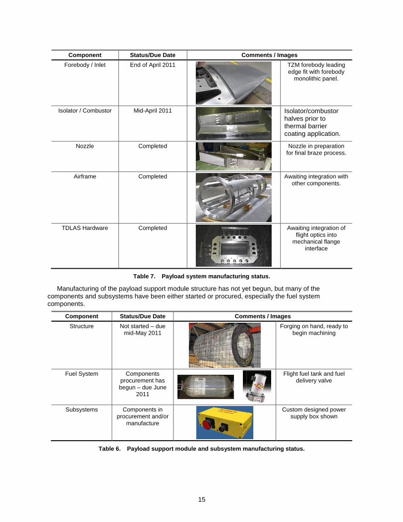
Manufacturing of the payload support module structure has not yet begun, but many of the components and subsystems have been either started or procured, especially the fuel system components.
Component Status/Due Date Comments / Images
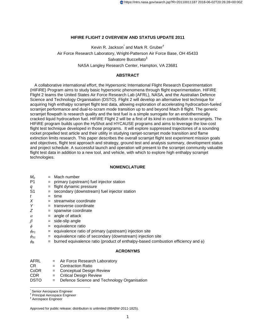
Forebody / Inlet End of April 2011
TZM forebody leading edge fit with forebody
monolithic panel.
Isolator / Combustor Mid-April 2011
Isolator/combustor halves prior to thermal barrier coating application.
Nozzle Completed
Nozzle in preparation for final braze process.
Airframe Completed
Awaiting integration with other components.
TDLAS Hardware Completed
Awaiting integration of flight optics into
mechanical flange interface
Table 7. Payload system manufacturing status.
Component Status/Due Date Comments / Images
Structure Not started – due mid-May 2011
Forging on hand, ready to begin machining
Fuel System Components procurement has begun – due June
2011
Flight fuel tank and fuel delivery valve
Subsystems Components in procurement and/or
manufacture
Custom designed power supply box shown
Table 6. Payload support module and subsystem manufacturing status.

16
STATUS AND SCHEDULE
The HIFiRE Flight 2 project has completed its system-level preliminary design review and is working to close its system-level critical design review even as many elements of the project are at or beyond a critical design maturity level. It is expected that the manufacturing for major payload components will be completed by May 2011, with integration of the payload system spanning the months of June and July. Integration and check-out of the payload system with the VIM and VSM sections will take place during August and September 2011 with full front-end test and evaluation following in October 2011. The date for flight is currently set for the first quarter of calendar year 2012. The current schedule is detailed in Figure 17.
SUMMARY
HIFiRE Flight 2 is a research flight experiment designed to explore the performance and operability of a hydrocarbon fueled scramjet combustor as it accelerates over a flight Mach number range from 6.0 – 8.5+. The primary objectives of the flight are to study dual-mode to scramjet-mode transition and Mach 8 hydrocarbon combustion performance and operability limits. In parallel with the primary research objectives, HIFiRE flight 2 is seen as a pathfinder to further develop the use of sounding-rocket technology in the study of hypersonic technologies, specifically those of air-breathing propulsion concepts. Secondary objectives include the exploration of the use of a tunable diode laser absorption spectroscopy system to monitor the production of water in the combustion products in flight. Other objectives include the verification and validation of design codes and analysis tools.
The LSP has performed trajectory studies that have shown the ability of the selected Terrier-Terrier-Oriole sounding rocket stack to achieve the defined test window, providing an ideal air-breathing corridor to accelerate a captive-carry payload from below Mach 6 to Mach 8.5 over a timeframe of approximately 10 seconds.
An extensive computational and ground test evaluation of the combustor configuration has been undertaken, demonstrating its ability to meet the research objectives. The flight vehicle design has closed with the 3-stage Terrier-Terrier-Oriole sounding rocket and supporting subsystems that meet the research and experimental requirements of the payload system. The payload design has been verified against its requirements and is essentially complete. Manufacturing of flight vehicle components is well underway, and with hardware delivery already beginning the flight 2 team is ready to move forward with integration, final assembly, and checkout. Upon completion of these activities, the team will perform final environment testing on the integrated payload system and then deploy to the range for final flight preparations and launch event.
TaskCY09 CY10 CY11 CY12
Q1 Q2 Q3 Q4 Q1 Q2 Q3 Q4 Q1 Q2 Q3 Q4 Q1
Payload / Payload Support Module (ATK)
Conceptual Design
Preliminary Design (Dec ‘08)
Detailed Design
Manufacture / Integration / Delivery
Launch Vehicle (WSMR)
Conceptual Design / System Req’ts
Preliminary Design
Detailed Design
Manufacture / Delivery
Flowpath Development (AFRL/NASA)
Combustor Analysis
Combustor Ground Test
Inlet Analysis
Flight (AFRL/NASA/WSMR)
Payload Integration & T&E
Payload Delivery (PMRF)
Payload Readiness Review
Range Readiness Review
Flight Test (February 2012)
CDR
Delivery
Delivery
PDR
CDR
Phase IIPhase I
Today
Delta
PDR
CDR
ΔSRR/CoDR
Figure 17. HIFiRE Flight 2 project schedule.
17
The efforts described in this paper and the future payload design and manufacture, analysis, ground test and integration efforts will culminate in a flight test currently scheduled for the first quarter of calendar year 2012. A successful launch and operation will provide valuable flight test data on a hydrocarbon-fueled scramjet combustor and demonstrate to the scramjet community a new technique and vehicle with which to explore high-enthalpy scramjet engines and related hypersonic technologies.
ACKNOWLEDGMENTS
The authors would like to acknowledge the HIFiRE Program for the opportunity to design and conduct experiments such as those described in this paper. The support of the HIFiRE management team, especially Mr. Doug Bowers and Mr. Doug Dolvin, is greatly appreciated, as has the support of Dr. Thomas Jackson, Mr. Robert Mercier, Dr. Michael Brown, and Mr. Todd Barhorst of AFRL/RZA. Our partnership and interaction with NASA Langley Research Center personnel, specifically Jim Pittman, Neal Hass, Andrea Storch, Karen Cabell, Paul Ferlemann, Michael Bynum, Keith McDaniel, and Ken Rock, have been very valuable. We also acknowledge the continued support of Randy Voland and Scott Gallimore of ACENT Labs in providing on-going guidance and filling the in the technical gaps as they have arisen. The efforts of design team at ATK, including Jeremie Villar, Michael Touma, and Ralph Woeful were critical to the continued development and maturity of the payload design. Finally, the efforts of the launch services team, including Sal Rodriguez at WSMR, Troy Gammill of Newtec. LLC, and Wayne Montag and Joshua Peterson at Kratos Rocket Support Services, has resulted in the selection of a launch range facility and the launch system components necessary to successfully complete the project.
REFERENCES
1 Dolvin, D., “Hypersonic International Flight Research and Experimentation Technology Development and Flight
Certification Strategy,” AIAA 2009-7228, Oct 2009. 2 Smart, M. K., Hass, N. E., and Paull, A., “Flight Data Analysis of the HyShot 2 Scramjet Flight Experiment,” AIAA
Journal, Vol. 44, No. 10, 2006, pp. 2366-2375. 3 Walker, S. H., Rodgers, F. C., and Esposita, A. L., “Hypersonic Collaborative Australia/United States Experiment
(HYCAUSE),” AIAA Paper 2005-3254, May 2005. 4 Kay, I. W., Peschke, W. T., and Guile, R. N., "Hydrocarbon-Fueled Scramjet Combustor Investigation," Journal
of Propulsion and Power, Vol. 8, No. 2, 1992, pp. 507-512. 5 Siebenhaar, A., Bulman, M., Norris, R., and Thompson, M., "Development and Testing of the Aerojet Strutjet
Combustor," AIAA Paper 99-4868, July 1999. 6 Mathur, T., Gruber, M., Jackson, K., Donbar, J., Donaldson, W., Jackson, T., and Billig, F., “Supersonic
Combustion Experiments with a Cavity-Based Fuel Injector,” Journal of Propulsion and Power, Vol. 17, No. 6, 2001, pp. 1305-1312.
7 Lin, K.-C., Tam, C.-J., Boxx, I., Carter, C., Jackson, K., and Lindsey, M., “Flame Characteristics and Fuel
Entrainment Inside a Cavity Flame Holder in a Scramjet Combustor,” AIAA Paper 2007-5381, July 2007. 8 Lin, K.-C., Jackson, K., Behdadnia, R., Jackson, T. A., Ma, F., Li, J., and Yang, V., “Acoustic Characterization of
an Ethylene-Fueled Scramjet Combustor with a Recessed Cavity Flameholder,” AIAA Paper 2007-5382, July 2007. 9 Foelsche, R.O., Beckel, S. A., Betti, A. A., Wurst, G. T., Charletta, R. A., and Bakos, R. J., “Flight Results from a
Program to Develop a Freeflight Atmospheric Scramjet Test Technique,” AIAA Paper 2006-8119, December 2006. 10
Boudreau, A. H., "Status of the U.S. Air Force HyTech Program," ISABE-2003-1170, September 2003. 11
Norris, R. B., "Freejet Test of the AFRL HySET Scramjet Engine Model at Mach 6.5 and 4.5," AIAA Paper 2001-3196, July 2001.
12 Mercier, R., and McClinton, C., "Hypersonic Propulsion - Transforming the Future of Flight," AIAA 2003-2732,
July 2003. 13
Lewis, Mark, “X-51a Scrams into the Future,” Aerospace America, October 2010, pp. 26-31. 14
McClinton, C. R., "X-43-Scramjet Power Breaks the Hypersonic Barrier Dryden Lectureship in Research for 2006," AIAA Paper 2006-0001, Janaury 2006.

18
15
Jackson, K., Gruber, M., Jackson, T., Hass, N., “HIFiRE Flight 2 Scramjet Experiment Overview,” 55th
JANNAF Propulsion Meeting, Newton, MA, May 2008.
16 Jackson, K., Gruber, M., Barhorst, T., “The HIFiRE Flight 2 Experiment: An Overview and Status Update,”
AIAA Paper 2009-5029, August 2009.
17 Hass, N., Cabell, K., Storch A., Gruber, M., “Scramjet Test Results of the HiFIRE Direct-connect Rig (HDCR) At
NASA Langley‟s Arc-Heated Scramjet Test Facility,” 17th AIAA International Space Planes and Hypersonic Systems
and Technologies Conference, San Francisco, CA (submitted for publication) 18
Dolvin, D., “Hypersonic International Flight Research and Experimentation Technology Development and Flight Certification Strategy,” AIAA 2009-7228, Oct 2009.
19 Williams, S., Barone, D., Barhorst, T., Jackson, K., Lin, K.-C., Masterson, P., Zhao, Q., Sappey, A. D., “Diode
Laser Diagnostics of High Speed Flows,” AIAA Paper 2006-7999, Nov 2006. 20 Storch, A., Bynum, M., Liu, J.; Gruber, M., “Combustor Operability and Performance Verification for HIFiRE
Flight 2,” 17th AIAA International Space Planes and Hypersonic Systems and Technologies Conference, San Francisco, CA (submitted for publication)
21 Ferlemann, P., “Forebody and Inlet Design for the HIFiRE 2 Flight Test,” 55th
JANNAF Propulsion Meeting,
Newton, MA, May 2008. 22 Gruber, M., Ferlemann, P., and McDaniel, K., “HIFiRE Flight 2 Flowpath Design Update,” JANNAF 43
rd / 31
st
APS / 25th
PSHS Joint Subcommittee Meeting, San Diego, CA, December 2009. 23 Kantrowitz, A., and Donaldson, C., “Preliminary Investigation of Supersonic Diffuser,” NACA WRL-713, 1945. 24 Gruber, M. R., Jackson, K. R., Jackson, T. A., and Liu, J., “Hydrocarbon-Fueled Scramjet Combustor Flowpath
Development for Mach 6-8 HIFiRE Flight Experiments,” 55th JANNAF Propulsion Meeting, Newton, MA, May 2008.
25 Liu, J., Gruber, M., “Preliminary Preflight CFD Study on the HIFiRE Flight 2 Experiment,” 17th AIAA
International Space Planes and Hypersonic Systems and Technologies Conference, San Francisco, CA (submitted for publication)
26 Colket, M. B., and Spadaccini, L. J., "Scramjet Fuels Autoignition Study," Journal of Propulsion and Power, Vol.
17, No. 2, 2001, pp. 315-323. 27 Pellett, G. L., Vaden, S. N., and Wilson, L. G., "Opposed Jet Burner Extinction Limits: Simple Mixed
Hydrocarbon Scramjet Fuels vs Air," AIAA Paper 2007-5664, July 2007. 28
Hass, N., Cabell, K., and Storch, A., “HIFiRE Direct-Connect Rig (HDCR) Phase I Ground Test Results from the NASA Langley Arc-Heated Scramjet Test Facility,” Presented at CS/APS/PSHS Joint JANNAF Meeting, December 2009.
29 Richman, M., Kenyon, J., Sega, R., “High Speed and Hypersonic Science and Technology,” AIAA Paper 2005-
4099, July 2005. 30 Lindstrom, C., Chung-Jen Tam, C.-J., Givens, R., Davis, D., and Williams, S., “Diode laser absorption
tomography using data compression techniques,” Proc. SPIE Vol. 6814, 68140W (Feb. 26, 2008). 31 Lindstrom, C., Tam, C.-J., Davis, D., Eklund, D., and Williams, S., “Diode Laser Absorption Tomography of 2D
Supersonic Flow,” AIAA Paper 2007-5014, July 2007. 32 Gruber, M., Barhorst, T., Jackson, Kevin, Eklund, D., Hass, N., Storch, A., Liu, J., “Instrumentation and
Performance Analysis Plans for the HIFiRE Flight 2 Experiment,” AIAA Paper 2009-5032, August 2009.