hierarchy in pdms_ world, site, zone
DESCRIPTION
used for beginnersTRANSCRIPT
2/21/2015 Hierarchy in PDMS: World, Site, Zone
http://www.pipingengineering.com/hierarchyinpdmsworldsitezone.html 1/5
⌂ Home » PDMS » Hierarchy in PDMS: World, Site, Zone
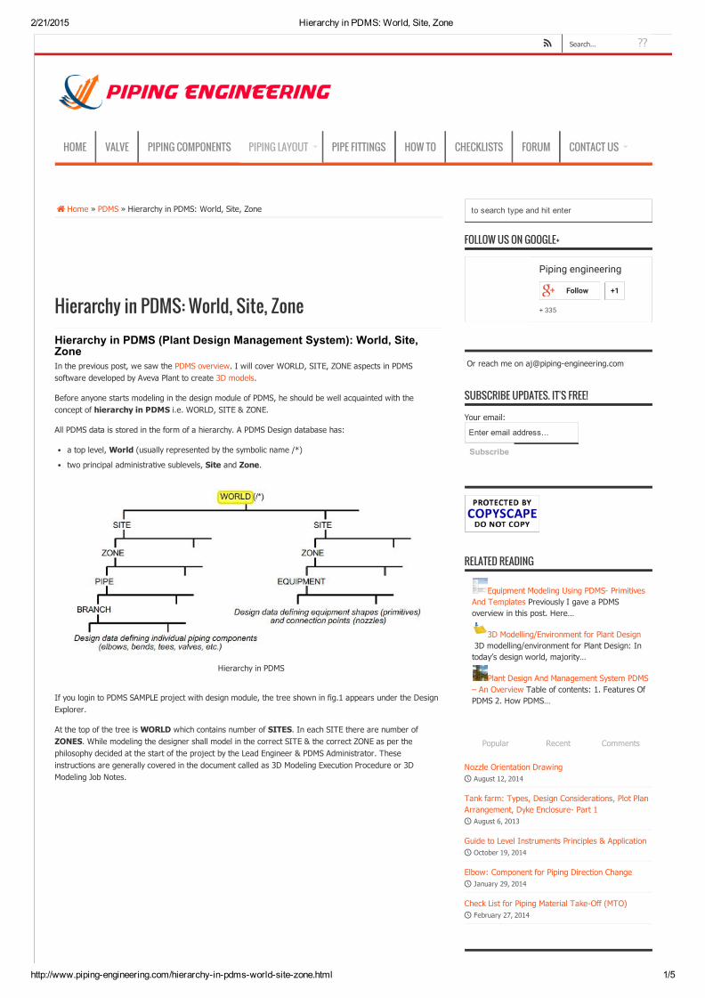
Hierarchy in PDMS: World, Site, ZoneHierarchy in PDMS (Plant Design Management System): World, Site,ZoneIn the previous post, we saw the PDMS overview. I will cover WORLD, SITE, ZONE aspects in PDMSsoftware developed by Aveva Plant to create 3D models.
Before anyone starts modeling in the design module of PDMS, he should be well acquainted with theconcept of hierarchy in PDMS i.e. WORLD, SITE & ZONE.
All PDMS data is stored in the form of a hierarchy. A PDMS Design database has:
a top level, World (usually represented by the symbolic name /*)
two principal administrative sublevels, Site and Zone.
Hierarchy in PDMS
If you login to PDMS SAMPLE project with design module, the tree shown in fig.1 appears under the DesignExplorer.
At the top of the tree is WORLD which contains number of SITES. In each SITE there are number ofZONES. While modeling the designer shall model in the correct SITE & the correct ZONE as per thephilosophy decided at the start of the project by the Lead Engineer & PDMS Administrator. Theseinstructions are generally covered in the document called as 3D Modeling Execution Procedure or 3DModeling Job Notes.
to search type and hit enter
FOLLOW US ON GOOGLE+
Or reach me on aj@pipingengineering.com
RELATED READING
Equipment Modeling Using PDMS PrimitivesAnd Templates Previously I gave a PDMSoverview in this post. Here…
3D Modelling/Environment for Plant Design 3D modelling/environment for Plant Design: Intoday’s design world, majority…
Plant Design And Management System PDMS– An Overview Table of contents: 1. Features OfPDMS 2. How PDMS…
Nozzle Orientation Drawing August 12, 2014
Tank farm: Types, Design Considerations, Plot PlanArrangement, Dyke Enclosure Part 1 August 6, 2013
Guide to Level Instruments Principles & Application October 19, 2014
Elbow: Component for Piping Direction Change January 29, 2014
Check List for Piping Material TakeOff (MTO) February 27, 2014
Piping engineering
+ 335
Follow +1
SUBSCRIBE UPDATES. IT'S FREE!
Your email:
Enter email address...
Subscribe
Popular Recent Comments
HOME VALVE PIPING COMPONENTS PIPING LAYOUT PIPE FITTINGS HOW TO CHECKLISTS FORUM CONTACT US
??Search...

2/21/2015 Hierarchy in PDMS: World, Site, Zone
http://www.pipingengineering.com/hierarchyinpdmsworldsitezone.html 2/5
Fig.1: Hierarchy in PDMS SAMPLE project
The concept of hierarchy can be explained with an example shown in fig.2
WORLD in PDMS:The complete plant area appearing in the Plot Plan or the overall layout can be considered as “WORLD” forthe Project. In the example the complete deck area highlighted in thick black border can be considered asthe area available as WORLD in the PDMS. All the PDMS modeling shall be limited within this area.
SITE in PDMS:In a project, the Plot Plan or the overall layout is divided into several subareas based on the sheet (A0 orA1) and the scale (eg. 1: 100 or 1:50) used for developing the equipment layout.
In the equipment layout for each subarea there are different equipment & components of each disciplinei.e. Mechanical Equipment, Piping, Electrical, Instrumentation, etc. These subareas are used to createSITES in PDMS.
In PDMS there are individual SITES created for different disciplines for each subareas. Referring to theexample the deck area is divided in to four subareas AREA1, AREA2, AREA3 & AREA4 by the thick redlines.
For AREA1, there are different SITES created in PDMS as PIP_AREA1, EQUIP_AREA1, STRU_AREA1,ELEC_AREA1, INSTR_AREA1 for modeling of Piping, Equipment, Structural, Electrical & Instrumentationrespectively. Similar SITES will be created for each of the subareas.
ZONE in PDMS:In each of the SITES created there are different categories of components which are required to bemodeled under each discipline.
For each category there is a ZONE created in PDMS.
eg. In a project there are different fluid codes or services (i.e. CD, CO, FW, OD, etc.), so the pipes can becategorized as per the fluid codes or services. Using the above categorization in the example there aredifferent ZONES created for each fluid code or service as PAREA1/PIPECD, PAREA1/PIPECO, PAREA1/PIPEFW, PAREA1/PIPEOD.
The above split of WORLD, SITE & ZONE can be seen in the Fig.3.
Generally in a project the creation of SITES & ZONES is the responsibility of PDMS administrator.
The PDMS designer will not have permission to create SITE & ZONE in the project. PDMS designer has therights only to model the equipment & component in the ZONE.
So while modeling the PDMS designer has to check the physical location of the component on the Plot plan &equipment layout then select the proper ZONE in PDMS before start of the modeling.
Google+
WebPageBlocked!
You havetried toaccess a webpage which isin violation ofyour internetusage policy.
URL:googleads.g.doubleclick.net/pagead/ads?client=capub4041440204688525&format=300x600&output=html&h=600&slotname=8212945961&adk=3219311102&w=300&lmt=1424503325&flash=16.0.0&url=http%3A%2F%2Fwww.pipingengineering.com%2Fhierarchyinpdmsworldsitezone.html&dt=1424503322961&bpp=12&bdt=19258&shv=r20150217&cbv=r20141212&saldr=aa&prev_slotnames=6004242764%2C1691731963&correlator=6769929633793&frm=20&ga_vid=1873135369.1424502985&ga_sid=1424503323&ga_hid=304232877&ga_fc=0&u_tz=330&u_his=1&u_java=1&u_h=900&u_w=1600&u_ah=860&u_aw=1600&u_cd=24&u_nplug=13&u_nmime=54&dff=tahoma&dfs=13&adx=974&ady=1492&biw=1592&bih=799&eid=317150304&oid=3&ref=http%3A%2F%2Fwww.pipingengineering.com%2Fequipmentmodelingusingpdmsprimitivesandtemplates.html&rx=0&eae=0&fc=24&brdim=0%2C0%2C0%2C0%2C1600%2C0%2C0%2C0%2C1600%2C799&vis=2&rsz=0%7C0%7Cm%7C&abl=NS&ppjl=f&fu=0&bc=1&ifi=3&xpc=fxohDTVMhS&p=http%3A/www.pipingengineering.com&dtd=2108
Sign up to get latest FREE articles right to yourinbox!
Your email:
Enter email address...
Subscribe Unsubscribe
×

2/21/2015 Hierarchy in PDMS: World, Site, Zone
http://www.pipingengineering.com/hierarchyinpdmsworldsitezone.html 3/5
In the example shown in fig.2, to model a pipe with line number CD4”AL0NL1PP in AREA1 you should beon the ZONE PAREA1/PIPECD to model the pipe.
The names used to identify database levels below Zone depend on the specific engineering discipline forwhich the data is used. For piping design data, the lower administrative levels (and their PDMSabbreviations) are:
• Pipe (PIPE)
• Branch (BRAN)
Fig 2 Example of a Deck layout

2/21/2015 Hierarchy in PDMS: World, Site, Zone
http://www.pipingengineering.com/hierarchyinpdmsworldsitezone.html 4/5
Fig .3: Hierarchy in PDMS for EXAMPLE project
Related Posts:Equipment Modeling Using PDMS Primitives And Templates Previously I gave a PDMS overview in thispost. Here…
3D Modelling/Environment for Plant Design 3D modelling/environment for Plant Design: In today’sdesign world, majority…
Plant Design And Management System PDMS – An Overview Table of contents: 1. Features Of PDMS 2.How PDMS…
PDMS Example for New Equipment Creation using Copy Offset… In this post, I will explain newequipment creation using…
PDMS – Example of Stretch/Trim using ID PPoint In the previous post we saw how Stretch/TrimFunctions in…
LEAVE A REPLY
Your email address will not be published. Required fields are marked *
Name *
Email *
Website
Check here to Subscribe to notifications for new posts

2/21/2015 Hierarchy in PDMS: World, Site, Zone
http://www.pipingengineering.com/hierarchyinpdmsworldsitezone.html 5/5
Post Comment
© copyright Piping engineering 2015 All Rights Reserved. Privacy Policy | About Us