hid’ing lightforce 140, 170 & 240 and nitestalker … · hid’ing lightforce 140, 170 &...
TRANSCRIPT

HID’ing Lightforce 140, 170 & 240 and NiteStalker 180 & 220 ROO lights. (20/May/2K9, v1.0k) Welcome! Thankyou for purchasing this adapter kit for the 140 Lance, 170 Striker and 240 Blitz, and also your general interest in HID technology. Please don’t have any fears at doing these mods as it really is dead simple. If you have any questions at any stage throughout these instructions, please don’t hesitate in contacting me. The easiest way is preferably via e-mail: [email protected] Or by leaving a message on my mobile phone: 0429 111 017. Please check my website for any updated information that may be available. http://lightforcehid.iscool.net Let the HID Lightforce / NiteStalkers be with ya! Cheers Dave (Bushy) Maunder
Overview The following instructions give a few simple steps to convert your Lightforce 240 Blitz lights from their original halogen bulb to use the newer HID light technology that is currently available at reasonable prices. LightForce originally chose to use the GA bi-pin series of bulbs in their series of lights – a bulb with two pins hanging off it. Their official name is “JCD bi-pin halogen bulb GY 6.35”, made by Osram and possibly a few other companies. The “GY 6.35” is what the bulb base or mount is called – that is, the distance between the middle of one pin to the other is 6.35mm. These halogen bulbs from Lightforce come in two voltages – 12 volts and 24 volts, with differing wattages of 35, 50, 75 and 100 watts. Lightforce sell the 12v 100w bulb for around $15.00 each. You can pick them up at Bunnings and the like for around $2.50 each! The problem What we have here are some awesome lights, but let down by early 19th century technology, ie power flowing through a wire filament to produce light but too much heat. What we need is more light, and less heat, whilst also sucking less juice. The answer Use HID technology – High Intense Discharge light. A glass bulb which has a bunch of gas in it, and when a high voltage passes through the gas, light is produced. Once lit, the voltage drops to around the 90 volt mark. When compared to older filament wire technology, 35watt HID’s produce a heap more light and less heat whilst using nearly a third of power. They are around about 85% in efficiency. 50 watt HID kits are closer to 92% efficient. That is 92% of electricity going into the HID system is converted into light and around 8% is converted to heat. High Intense Discharge bulbs utilise new technology to give up to 300% more light output (300% for a 35 watt HID kit, closer to 450% for a 50 watt HID kit) than the equivalent halogen bulb whilst drawing much less current. The higher voltage strikes an arc through the xenon inert gas inside the bulb and converts more power to light. Due to less heat being given off, the bulbs life is at least twice that of a standard halogen bulb - 3000 odd hours. A quick example: a pair of original Blitz’s that utilise the bi-pin 100 watt bulb. For a 12v 100watt bulb, the current draw is approximately 8.3 amps, however this will vary between 7 to 9 amps each in reality. A 35 watt HID bulb will produce much more light output and will only require 2.5 to 3 amps each. Compare six 100 watt halogens (600 watts – 50 odd amps) verses six 35 watt HID bulbs (210 watts – 17 odd amps).

Background The idea came about because after seeing a set of real Lightforce HID lights at a 4wd winching competition back in 2002, I really really wanted a set. But I didn’t really really want to pay the dollars for them. I went down the path of asking sales @ lightforce for some sort of a cheap deal for a set of real HID lights, whilst giving heaps of advertising. Of course they didn’t bother responding. So my mind went walk-a-bout and started thinking surely it is possible. At the time HID kits were still very expensive, however these days the kits are available for a few hundred dollars. So my mind went walk-a-bout and started thinking surely it is possible. The current look of the adapter is my second design, and I wish to thank a bloke by the name of Craig Light for the initial Autocad drawing. I’m sure that you might be a bit disappointed upon opening to find that you’ve just spent good dollars on a bit of lousy 1mm cut mild sheet. And yes, I can understand that. I wanted to get these cut much cheaper than what I did, however I couldn’t. Unfortunaetely I don’t have access to some sort of stamping machine or even a cheap plasma/laser cutter, and is the reason at why these are so expensive for what they are. I apologise for that. Anway, a lot of time and effort went into this document and secondly I have now successfully converted a lot of different lights to HID’s, and the majority of the instructions are freely available for download in Microsoft Word documents on my HID site http://www.hid.isclever.com . And since I’ve spent sooooo much money on lights and HID kits over the past six to twelve months, I need to get a little bit of it back - I highly doubt I ever will. Most of the money has gone into research and development in order to give free information about converting other types of lights. Before this, information on such modifications were not available – believe me, I have spent months crawling google and yahoo looking for such information, and I reckon it doesn’t exist. I just hope that you can understand and appreciate this. The current design of the adapter will also fit a standard H3 halogen bulb to these lights. Why would you want to do that? Maybe some peeps would like to have 130 watt halogen bulbs in their Lightforce lights. Or maybe they’d like a 55 watt H3 bulb – since they can be bought for a few dollars. The option is there. Disclaimer PLEASE NOTE: Attempting any type of modification on any of your Lightforce lights will void your warranty. Please make sure that you fully comprehend what you are about to do. If your lights are still in warranty Lightforce do actually have a very good warranty service. You might just want to fire off an email and find out exactly what they will cover before going ahead with these mods. (Just had to include this). Anway, enough yabbering. Lets get into it! The following is a list of everything that you need to do this conversion: * At least one LightForce 240 light! Two is preferable. Four is better. Six is wild. Eight on the roof wont fit! * One H3 bulb HID kit. Your choice of colour temp – 5000k is daylight white, 6000k is more blue-ish. Tools required: * Diagonal side cutters, long nose pliers or even scissors will do. * Small round file, ie chainsaw file. * Small flat file * Drill press * 19mm or ¾” drill bit if no cable gland is to be used – just silicon. (optional) * 25mm drill bit if a M25 cable gland is to be used. (optional) * 25mm M25 cable gland (optional) * 17mm socket - if Blitz lights are still bolted to the car. * Knife - if Blitz lights are still in original box. * Small flat bladed screwdriver. * Small philips bladed screwdriver. * Inert Silicon. As noted from Peter Culley of Lightforce Australia, it is highly recommended to purchase some non-acidic ‘inert’ silicon, since the acidic vapours that is released whilst the silicon cures will destroy the reflective coating on the reflector lens, as well as not helping much with the inside of the clear outer protective lens. ‘Inert’ being a silicon silastic that does not give off acidic fumes. There are a few around on the market – such as some white and black coloured silicones.

Fitting instructions All photos in this document are for the Lightforce range of lights. Please be assured that these adapter mounts will also fit the NiteStalker lights. Just use the exact same steps as shown. Unscrew the lens. With a screwdriver lift up the heat shield material on the bulb housing/mount and gently bend the three inner arms. The entire bulb housing will then be able to be pulled out approx 25mm. Cut any plugs off the ends of the leads, and with a gentle pull of the bulb housing the wires should pull all the way through the light mount. There will be silicon on the inside of the light hosuing waterproofing the original wires. Some of this silicon may need to be removed by either scraping with a flat blade screwdriver or carefully with knife. Do not do this if you are unable to handle a knife! Do not cut yourself! Do not slip and accidently mark the kitchen table! Don’t let the wife have to clean up the blood and then have take you to the hospital This photo shows the Lightforce original lens mount (herein called ‘LF early mount’). These are found on the Lancer 140, Striker 170 and Blitz 240. Below is the ‘high mount’ - available on the 140, 170 and 240 Blitz. A ‘low mount’ is only available for the Lancer 140 and Striker 170. This photo below left shows the Lightforce newer “version 2” mount (herein called ‘LF late mount’) with its heatsink removed These are found in the Lancer 140, Striker 170 and Blitz 240. Hard to put an exact date when these were released. Maybe early 2003 perhaps. Probably a similar time when the XGT was released.
The LF late mount has a distinctive ‘Lightforce’ written down its side and the orignal bulb wiring comes out facing downwards halfway down the spine of the mount.
This photo shows the difference between the old and new style of the bi-pin halogen bulb mount. The late style (right) is a chunk of billet aluminium which is much better at absorbing and
disapating heat from the bulb than the early version did.

With a 25mm drill bit or hole saw, drill a hole in the centre of the rear of the light mount mount. The unclear item on the left of the photo is a 25mm hole saw (yes, it is a bad photo). At your local electronics shop purchase a 25mm plastic cable gland. These can be obtained from your half-decent local commercial/industrial electrician. Or from these two Aussie electronic companies. RS Components, (www.rswww.com.au). Farnell (www.farnellinone.com.au). Ph: 1300 656636 Ph: 1300 361005. 25mm hole: stock# 365-8488. 25mm hole: order code 927-740. The corners of the plastic nut will need some slight filing in order for it to fit inside. Apply a dab of silicon to the inside of the housing via the rear hole, and then insert the plastic nut. Screw the gland into the rear and into the nut. Next, bend the legs of the HID bulb mount with a pair of pliers. Bend the sides of the arrows in a fraction for the arrows to dig in to the side of the light mount when inserted.

Carefully insert the bulb through the hole and screw the bulb to the bulb mount. Pass the wire connectors through the front of the light mount and through the opening of the plastic gland. With a bit of applied force the bulb adapter mount should fit snuggly into the light housing. If not, pull it back out, and bend the legs out a fraction more. If you are concerned that the adapter may move over time, add a dab of silicon to the legs. LF early ‘high’ mount against a LF late ‘high’ mount. Note the thread length difference. Note the differing high voltage connectors that are supplied from different manufactures.

This page is for the early version of the Lightforce 140/170/240 lights only. For a wide-ish beam which will leave a small dark spot in the centre when the lens is fully wound in for ‘spot’, mount the bulb as follows. You may wish to mount the screws or bolts in the reverse direction of that in the photos – so that it looks slightly nicer than in these ugly first-attempt R&D photos. Your adapters will also have a larger opening than in these photos, allowing a greater range of varying manufactures HID bulbs. For a spot, the bulb must be mounted as follows. You will need to pass the ends of the HID bulb through the hole in the mount, and then screw the bulb in as follows. This allows the extra few mm of clearance that is required for the arc of the bulb to be in the correct original focal point – as that of the factory halogen bi-pin bulb. You should not have to bend the second set of legs near the outter rigs. This produces a nice spot when the lens is fully wound in, and gives a wide beam as the lens is adjusted outward (turned counter clockwise) The correct distance between the edge of the LF mount and the halogen filament and/or HID arc is 22mm. All HID bulbs should be to a world wide standard, and the centre arc should be the exact same length as that in the photo. However the end of the bulbs may be shorter due to newer fancier designs – which will improve projectory angle and reduce such black spots as mentioned above. The correct orientation of the bulb is such that the external wire along the glass bulb should be closest to the ground, ie, down.
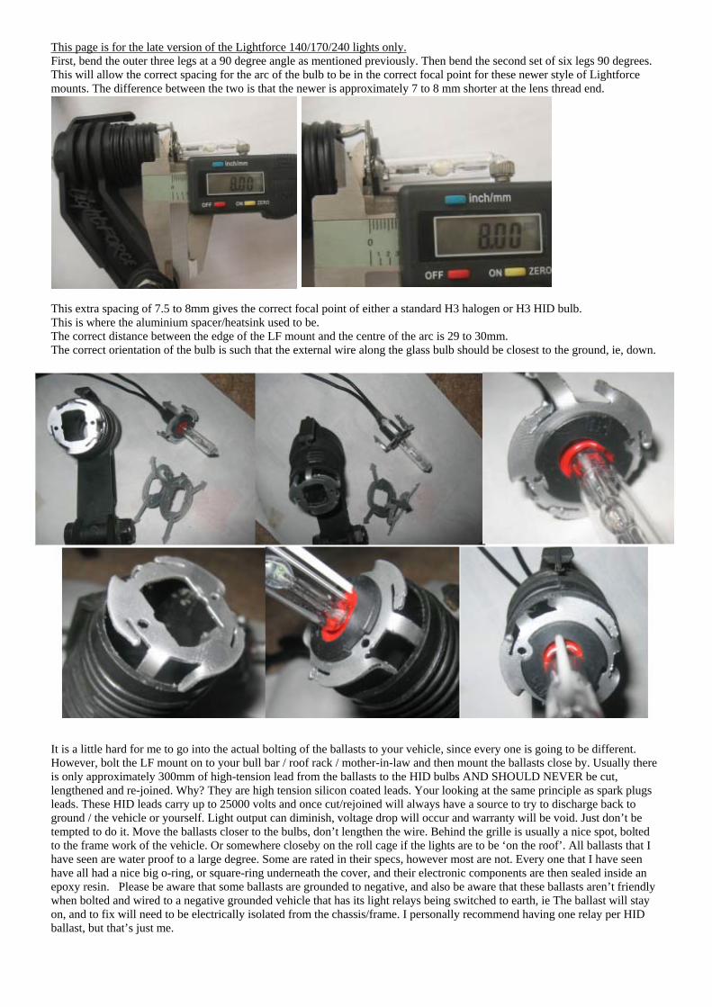
This page is for the late version of the Lightforce 140/170/240 lights only. First, bend the outer three legs at a 90 degree angle as mentioned previously. Then bend the second set of six legs 90 degrees. This will allow the correct spacing for the arc of the bulb to be in the correct focal point for these newer style of Lightforce mounts. The difference between the two is that the newer is approximately 7 to 8 mm shorter at the lens thread end. This extra spacing of 7.5 to 8mm gives the correct focal point of either a standard H3 halogen or H3 HID bulb. This is where the aluminium spacer/heatsink used to be. The correct distance between the edge of the LF mount and the centre of the arc is 29 to 30mm. The correct orientation of the bulb is such that the external wire along the glass bulb should be closest to the ground, ie, down.
It is a little hard for me to go into the actual bolting of the ballasts to your vehicle, since every one is going to be different. However, bolt the LF mount on to your bull bar / roof rack / mother-in-law and then mount the ballasts close by. Usually there is only approximately 300mm of high-tension lead from the ballasts to the HID bulbs AND SHOULD NEVER be cut, lengthened and re-joined. Why? They are high tension silicon coated leads. Your looking at the same principle as spark plugs leads. These HID leads carry up to 25000 volts and once cut/rejoined will always have a source to try to discharge back to ground / the vehicle or yourself. Light output can diminish, voltage drop will occur and warranty will be void. Just don’t be tempted to do it. Move the ballasts closer to the bulbs, don’t lengthen the wire. Behind the grille is usually a nice spot, bolted to the frame work of the vehicle. Or somewhere closeby on the roll cage if the lights are to be ‘on the roof’. All ballasts that I have seen are water proof to a large degree. Some are rated in their specs, however most are not. Every one that I have seen have all had a nice big o-ring, or square-ring underneath the cover, and their electronic components are then sealed inside an epoxy resin. Please be aware that some ballasts are grounded to negative, and also be aware that these ballasts aren’t friendly when bolted and wired to a negative grounded vehicle that has its light relays being switched to earth, ie The ballast will stay on, and to fix will need to be electrically isolated from the chassis/frame. I personally recommend having one relay per HID ballast, but that’s just me.

Wiring your ballasts up like this will cause no problems at all. Or just simply electrically isolate the ballast housing from the vehicles (usually) negative earth, and connect to your existing spotlight wiring.
If your kit arrives like this kinda weird setup (12v leads going through rubber grommet with the high tension leads), just cut the grommet and throw it away. 12v wires go to battery/relay, and the high tension leads go to the lights… Note which way the 12v source plug goes on to the ballast!! It is possible that on some ballasts the plug will fit reversed (with a bit of force involved). Most ballasts/ignitors will have diode protection, but don’t expect the real cheapies to have it.
Walla! Awesome light output. Depending on the colour that you have opted for, your lights will be yellow (4500k), daylight clear (5000k), blue tinge as below (6000k), blue (8000k) or starting to go purple (10000+ K)
Four LF240's with original bi-pib bulbs Two LF240's with H3 6000k HID bulbs 400 watts total 70 watts total.
(instant normal standard photo settings (100 film) with flash off)
LF240 Blitz - 35 watt each - SPOT LF240 Blitz - 35 watt each – WIDE (400 film setting on digi camera) (400 film setting on digi camera)
Why are HID lights totally blue for a few seconds after startup?
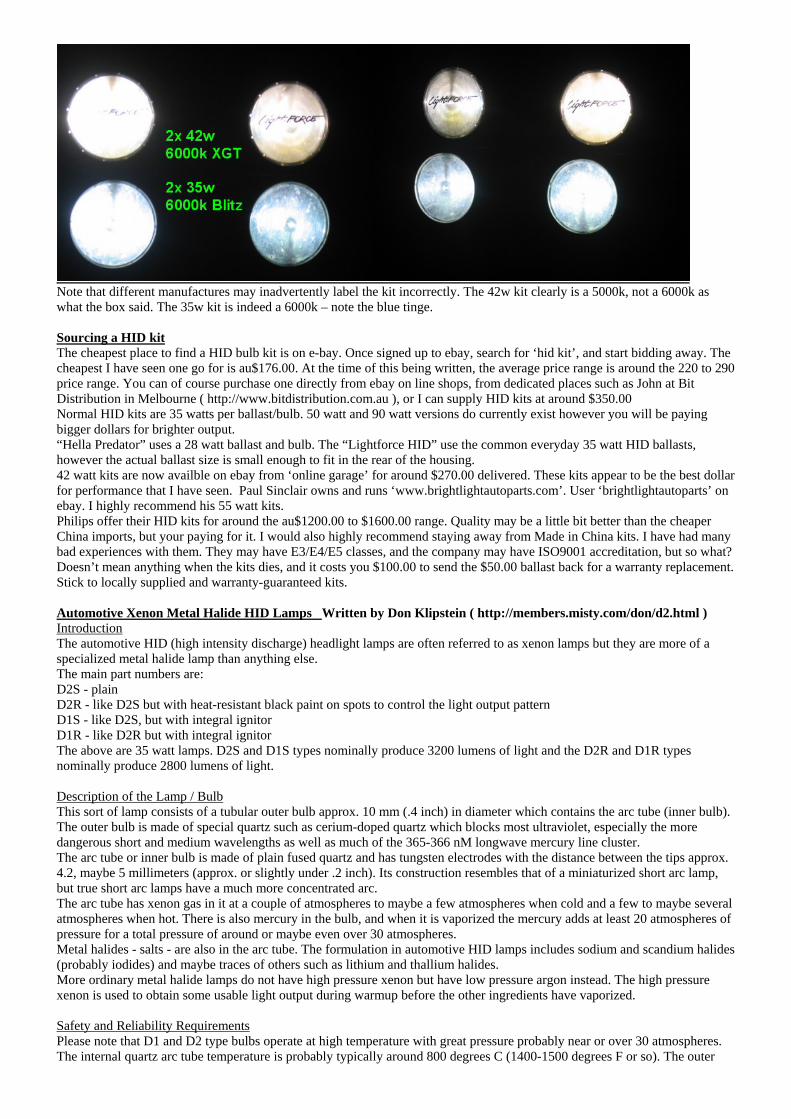
Note that different manufactures may inadvertently label the kit incorrectly. The 42w kit clearly is a 5000k, not a 6000k as what the box said. The 35w kit is indeed a 6000k – note the blue tinge. Sourcing a HID kit The cheapest place to find a HID bulb kit is on e-bay. Once signed up to ebay, search for ‘hid kit’, and start bidding away. The cheapest I have seen one go for is au$176.00. At the time of this being written, the average price range is around the 220 to 290 price range. You can of course purchase one directly from ebay on line shops, from dedicated places such as John at Bit Distribution in Melbourne ( http://www.bitdistribution.com.au ), or I can supply HID kits at around $350.00 Normal HID kits are 35 watts per ballast/bulb. 50 watt and 90 watt versions do currently exist however you will be paying bigger dollars for brighter output. “Hella Predator” uses a 28 watt ballast and bulb. The “Lightforce HID” use the common everyday 35 watt HID ballasts, however the actual ballast size is small enough to fit in the rear of the housing. 42 watt kits are now availble on ebay from ‘online garage’ for around $270.00 delivered. These kits appear to be the best dollar for performance that I have seen. Paul Sinclair owns and runs ‘www.brightlightautoparts.com’. User ‘brightlightautoparts’ on ebay. I highly recommend his 55 watt kits. Philips offer their HID kits for around the au$1200.00 to $1600.00 range. Quality may be a little bit better than the cheaper China imports, but your paying for it. I would also highly recommend staying away from Made in China kits. I have had many bad experiences with them. They may have E3/E4/E5 classes, and the company may have ISO9001 accreditation, but so what? Doesn’t mean anything when the kits dies, and it costs you $100.00 to send the $50.00 ballast back for a warranty replacement. Stick to locally supplied and warranty-guaranteed kits. Automotive Xenon Metal Halide HID Lamps Written by Don Klipstein ( http://members.misty.com/don/d2.html ) Introduction The automotive HID (high intensity discharge) headlight lamps are often referred to as xenon lamps but they are more of a specialized metal halide lamp than anything else. The main part numbers are: D2S - plain D2R - like D2S but with heat-resistant black paint on spots to control the light output pattern D1S - like D2S, but with integral ignitor D1R - like D2R but with integral ignitor The above are 35 watt lamps. D2S and D1S types nominally produce 3200 lumens of light and the D2R and D1R types nominally produce 2800 lumens of light. Description of the Lamp / Bulb This sort of lamp consists of a tubular outer bulb approx. 10 mm (.4 inch) in diameter which contains the arc tube (inner bulb). The outer bulb is made of special quartz such as cerium-doped quartz which blocks most ultraviolet, especially the more dangerous short and medium wavelengths as well as much of the 365-366 nM longwave mercury line cluster. The arc tube or inner bulb is made of plain fused quartz and has tungsten electrodes with the distance between the tips approx. 4.2, maybe 5 millimeters (approx. or slightly under .2 inch). Its construction resembles that of a miniaturized short arc lamp, but true short arc lamps have a much more concentrated arc. The arc tube has xenon gas in it at a couple of atmospheres to maybe a few atmospheres when cold and a few to maybe several atmospheres when hot. There is also mercury in the bulb, and when it is vaporized the mercury adds at least 20 atmospheres of pressure for a total pressure of around or maybe even over 30 atmospheres. Metal halides - salts - are also in the arc tube. The formulation in automotive HID lamps includes sodium and scandium halides (probably iodides) and maybe traces of others such as lithium and thallium halides. More ordinary metal halide lamps do not have high pressure xenon but have low pressure argon instead. The high pressure xenon is used to obtain some usable light output during warmup before the other ingredients have vaporized. Safety and Reliability Requirements Please note that D1 and D2 type bulbs operate at high temperature with great pressure probably near or over 30 atmospheres. The internal quartz arc tube temperature is probably typically around 800 degrees C (1400-1500 degrees F or so). The outer

bulb is not this hot, but it is definitely burning hot. The arc tube always has at least some miniscule risk of exploding and should only be operated in a headlight housing or other suitable container. Improper operation increases the risk of bulb explosion. The bulb must be clean and free of dirt, grease, organic matter, ash, salt, or alkali. Salts, ash, and alkalis have a tendency to slowly leach into red-hot and nearly red hot quartz which will result in strains, weak spots, and maybe cracks. A metal halide lamp does not like frequent starting. D1 and D2 types can be blinked, but this should only be done for a limited amount of time. Starting causes wear on the electrodes. Excessive evaporation of electrode material will deposit it onto the inner surface of the arc tube which results in darkening and overheating of the arc tube. In D1 and D2 and some other metal halide lamps, there is a halogen cycle which cleans deposited tungsten electrode material from the inner surface of the arc tube. Prolonged continuous operation at proper internal temperatures is required for the halogen cycle to work. Legality of Auxiliary Headlights ADR 77 covers everything about Gas Discahrge Headlamps. We’re not interested at all in headlamps, but what the ADR call “auxiliary driving lamps”, or commonly known to the rest of us as “spotties”. All my searches so far on the exact wording of this matter have ended up with very little information. Lightforce 240HID’s and Hella Predators are legal within Australia. Lightforce XGT has the exact same lens as that of the Lightforce 240HID. Hella Rallye 4000 has the exact same lens as that of the Hella Predator. Electrical Requirements The electrical requirements of D2 type lamps are nasty. They require ballasts which are more difficult to homebrew than other ballasts. I strongly encourage hobbyists, do-it-yourselfers, and hackers to *NOT* try this. Try homebrewing a D2 ballast only if you have the patience of two saints, lots of electrical and electronic project skills including high voltage skills and skill in homebrewing high voltage transformers with the combined difficulties of flyback transformers and xenon trigger transformers, and a budget for replacing lots of blown parts before you get it working. You are better off buying ballasts from Osram, Bosch, or Aromat (a division of Matsushita) or others. For one thing, these lamps require special sockets made by few manufacturers and mostly sold only to ballast manufacturers. The D2 types require a starting pulse. 7 kilovolts may on an average spark through these bulbs, but for reliability you need more, maybe 10 or possibly 12 kilovolts. Automotive use requires ability to restart a hot bulb with the mercury vapor pressure high, and this requires even more voltage - 12 to 15 kilovolts and maybe even more for good reliability. The usual ballasts supposedly produce starting pulse voltages like 18 kilovolts minimum, 20 kilovolts typical. D1 types have an integral ignitor which the ballast has to work with. Starting pulses must be repeated frequently until the arc is established. The ballast must supply an open circuit output voltage - other than the starting pulses - of over 300 volts, preferably 400 or maybe preferably 450 volts - to force the arc to establish. D1 and D2 type lamps are 35 watt lamps. Once the arc is established, the ballast must supply limited current or else the arc will draw extreme current and this will be bad for the bulb and/or other parts. The voltage across the lamp is normally around 80-90 volts when it is warmed up, but will be less during warmup. The ballast must handle a lamp voltage possibly as low as 16 volts early in warmup, although this voltage usually bottoms out higher - probably at least in the 20's of volts. The ballast must deliver 35 watts to the lamp when the voltage across the lamp is between 70 and 110 volts. When this voltage is lower, the ballast must deliver at least .5 amp but generally no more than 2 amps and preferably as close to 35 watts as possible. Higher currents are preferred - a partially warmed up metal halide lamp sometimes has an unstable arc at lower current. An automotive grade ballast often delivers boosted power (above 35 watts) at some times during warmup to give near-full light output. Note that a xenon arc or a mercury vapor arc does not produce visible light as efficiently as a metal halide arc does. Automotive grade ballasts with boosted power at some points of warmup have circuitry that models the thermal characteristics of the bulb. The maximum safe current for the bulb's electrodes must not be exceeded during a power boost during warmup. A voltage across the bulb higher than 110 volts only occurs in the early stage of establishing the arc or if the bulb is failing. The ballast should deliver enough power to heat up the electrode tips enough for the arc to establish - more is better and over 35 watts is OK as long as the current is not excessive. But excessive power delivered to an aging bulb can cause the bulb to explode. D1 and D2 lamps and most other metal halide lamps require AC. DC is tolerable briefly, and then preferably only if the bulb is cold. A DC electric field, hot quartz or hot glass, and salts or alkalis is not a good combination - electrolysis effects can occur which can create weak spots or cracks in the arc tube. The AC delivered to a D1 or D2 type bulb usually has a frequency of a couple hundred to a few hundred Hz. Higher frequencies are probably OK with D2 types but the ignitors in D1 types may only work correctly or even be adequately conductive in a certain range of frequencies. The AC current waveform in a D1 or D2 type lamp is traditionally a squarewave or close to a squarewave. Other waveforms have higher peak current for a given average current or RMS current, and the higher peak current is harder on the electrodes and may shorten the life or cause problems with the use of higher currents during warmup. Metal halide lamps should not be overpowered, except where permissible for accelerated warmup and near-full light output during warmup. Overpowering one will shorten its life and increase the risk of the lamp exploding. Underpowering a metal halide lamp is also bad. If the electrodes are not hot enough, they do not do a good job of conducting electrons into the arc and voltage drop in this process (known as the "cathode fall") is excessive. Excessive cathode fall causes positive ions in the arc to hit the electrode at excessive speed which "sputters" electrode material onto the inner surface of the arc tube. It is not recommended to experimentally operate metal halide lamps at reduced power. Besides the bad effects of high cathode fall on hot electrodes, an unusual temperature pattern can have the chemicals in the arc tube condense in locations that can block some of the light. And if the electrode cathode falls are excessive and unequally so, a DC electric field can result, which can cause destructive electrolysis effects on hot salts on hot quartz. This can cause the arc tube to crack. Metal halide lamps should have power input within 10 percent of their rated wattage. Why some HID lights stay “blue” after warm-up 1) To capture the blue light produced at the arc terminators on a continuous basis, some OEM manufacturers design (deliberately point) a small portion of the reflector to capture the “flat” blue light generated at the anode, and incorporate it as part of the total light output, by design.

2) Other OEMs will just “leave it alone”, knowing that, after a 100 hours or so of “burn time”, the anode will change shape, because of the constant electrical discharge. When this shape change occurs, the anode is no longer ground flat, and the shape of the blue secondary light at the anode changes from a flat, nearly two-dimensional, shape, to something that is three-dimensional. At this time, you have something that the reflector can use, and, you’ve got blue-tinted light, all the time. 3) A trend for “blue” lights has caused several HID capsule makers to “fiddle with” the metallic salt mix just for the aftermarket. By incorporating different metals, specifically Indium, the HID arc can continuously fluoresce at higher color temperatures with the same amount of voltage as used in the “lower color temperature” HID capsules. Results have been mixed, depending on the optics of the final applications. This is due to the “stratified light” nature of the stabilized HID arc, and how the reflector focuses on the total arc “layers”. Also, the use of different metallic salts may also decrease the useful life of the HID capsule, through quicker metal deposition on the capsule walls. Note: Indium is a material also used to plate mirrors, via a cathode/anode process. Info on HID lights. – blue light output Without going into the physics of electron orbits, photon pumps, valences, and other arcane stuff, it has to do with; The ballast/igniter, the nature of the arc terminators (cathode -, and anode +), the ignition (startup) current, the vaporizing metallic salts, and the constant Xenon gas fill. When a cold (room temperature) automotive HID is first turned on, the startup voltage produced by the igniter (sometimes separate, sometimes integrated into the ballast) is in the neighborhood of 20,000-25,000 volts. This high voltage potential forces the current at the arc generating point (cathode -) to leap the gap to the arc receiving point (anode +), identical to what happens with an arc welder. As the “leaping arc” contacts the anode, a number of interesting things start to happen; Light is produced along the arc length, through excitation of the gas molecules of the (constant) Xenon-fill gas. At this point, the arc is quite “fat” and at a very high color (blue) temperature. Robust high temperature blue light is also produced at the anode surface, and (to a lesser extent) at the cathode. This secondary light source (above) is extremely blue (+/- 10,000K), and also semi-spherical in nature, which allows this light source to be reflected by the system’s optics. The arc welder process generates heat, causing the metallic salts also contained in the capsules to begin to vaporize into gas, or gasses. This heating process causes other changes: As the gasses are generated, pressure inside the capsule begins to rise, from a static pressure of 5 atmospheres (from the Xenon fill), to a terminal point of more than 30 atmospheres. Total pressurization takes (typical) 30 seconds to occur. As the pressure increases in the capsule, less voltage is required to sustain the arc (electron flow), and the ignition current is dropped, via the ballast sensing circuitry, in a tapering fashion. This causes the arc to shrink in diameter and stabilize, as well as reduce the electrode surface sources of “blue” light. Note: The electrode (secondary) light sources are now very flat, like an LED, making them difficult to be captured by the reflector surface, because the reflector is designed to reflect axially produced light. What happens at this point is that the blue light (apparently) goes away. This is because; the arc is shrunken and stabilized, the voltage has been reduced to “arc sustaining”, the fluorescing gasses are running at a lower color temperature, and most of the usable (i.e., by the reflector) light is being generated just along the arc’s axial length. This “sustaining arc” has very little visible blue light, and the flat electrode-generated light is “invisible” to the reflector. Result: No more blue light. -- Produced by Ekooke
Various pictures of mounting the ballast with handhelds, along with the differences between the Lightforce and Roo heatsinks. Updated 13th December 2006. The Blitz H3 HID bulb adapter mount is now into its 3rd design and are now laser cut. A huge improvement over the original design and being cut by a plasma cutter. The deisng also now includes a 5mm hole in the top for those who wish to insert a single 5mm white LED and then connect it up to their parking lights for a cool look when running around town. This is legal in all states and territories as at December 2006. (Of course, if you go wild and chuck in a blue LED, this wont be legal in any state. Green would look nice.)
Can either purchase a white 12v 5mm LED from Jaycar or buy a normal standard LED and solder in series a 560 or 680 ohm ¼ watt resistor. (colour coding is green blue brown or blue violet brown). Should be a nice tight fit, if not, use a bit of glue or silicon. If you do not wish to install a LED, cover the hole with a smear of silicon. Update: March 2008 Fourth design of the bulb adapter has been made and has improvements over the prior design.
New v3 vs old. (laser cut vs plasma cut. Weren’t they rubbish…)
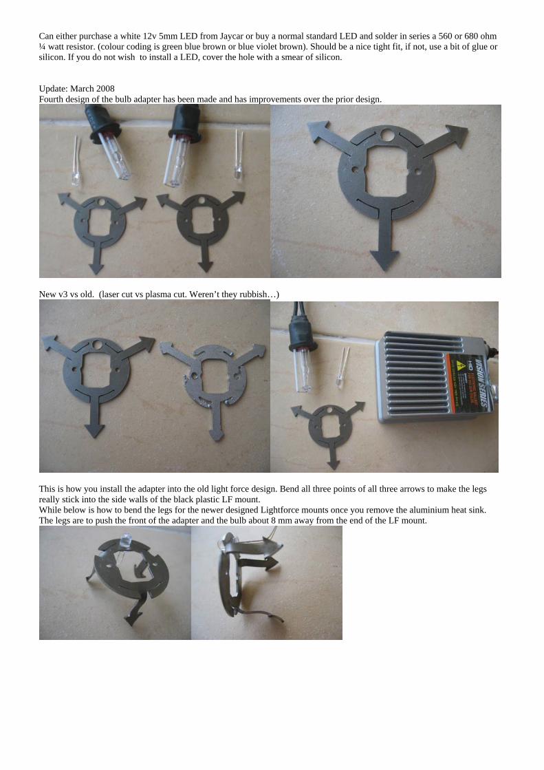
This is how you install the adapter into the old light force design. Bend all three points of all three arrows to make the legs really stick into the side walls of the black plastic LF mount. While below is how to bend the legs for the newer designed Lightforce mounts once you remove the aluminium heat sink. The legs are to push the front of the adapter and the bulb about 8 mm away from the end of the LF mount.

Piccy of a 45 watt 5000k XGT against a 35 watt 6000k Blitz which is dialed in to the same spot size. Left is 100ms open shutter, right is 400ms open shutter. Excuse the junk laying around.
And finally, if you are peeved off at spending $15.00 and you reckon that none of this has been worth it, then you can always try this as a last resort, as long as you have the current latest 170/240 design. All credits go to a bloke by the name of Len Fulham for this picture and his parting words. “I didnt use your adapters as I realised the metal lamp holder could be machined to suit - photo attached. I closed the rear of the LF with a castor plug used for round table legs - split it lengthwise so the wires come through the central hole which I closed with silicon.” The aluminium heatsink can easily be drilled with a 3mm drill bit, tapped with an M3 metric tap and a common metric 3 bolt with a little washer can be utilised to hold the bulb in place.

Piccy of my mate Hath. 4x 35w kits mounted in his bull From left: HID H3, Osram 100w bi-pin, halogen H3, Lights. Best thing about Bull lights is that they are large HID H1, halogen H1. Enough for the ballasts to fit inside. Light output for 140 total watts is just crazy. Applications HID lamps are typically used when high levels of light over large areas are required, and when energy efficiency and/or light intensity are desired. These areas include gymnasiums, large public areas, warehouses, outdoor activity areas, roadways, parking lots, and pathways. More recently, HID lamps, especially metal halide, have been used in small retail and residential environments. HID lamps have made indoor gardening practical, especially for plants that require a good deal of high intensity sunlight, like vegetables and flowers. They are also used to reproduce tropical intensity sunlight for indoor aquaria. Some HID lamps such as Mercury Vapor Discharge produce large amounts of UV radiation and therefore need diffusers to block that radiation. In the last few years there have been several cases of faulty diffusers, causing people to suffer severe sunburn and Arc eye. Regulations may now require guarded lamps or lamps which will quickly burn out if their outer envelope is broken. Recently, HID lamps have gained use in motor-vehicle headlamps. This application has met with mixed responses from motorists, mainly in response to the amount of glare that HID lights can cause. However, many motorists still prefer these lights as they emit a clearer, brighter, more natural appearing light than normal headlamps. They almost always have an automatic self-leveling system to minimize this issue and as such are usually an expensive optional extra on most cars. HID lamps are also being used for all external lights on the Airbus A380 superjumbo airliner and on many other general aviation aircraft for landing and taxi lights.

Watts Watts is a measurement of the current draw. A watt is the unit of electrical power equal to 1 ampere (amp) under a pressure of 1 volt. (Its also equal to 1/746 horsepower for what it's worth). Amperes are the rate at which electricity flows through a wire or piece of machinery. A good analogy is water through plumbing. When you open a faucet on a sink, water flows out at a certain rate. The same thing occurs when you turn on an auxiliary light. Electricity flows at a certain rate. This is amperes. Watts are the amount of energy a device uses in performing its function. To get watts, you multiply volts x amps. For example, a typical set of offroad auxiliary lights might draw about 4.6 amps. 12 volts x 4.6 amps = 55.2 watts. To get amperes, divide watts by volts. Examples: 55 watt auxiliary lights would calculate like this: 55 watts / 12 volts = 4.58 amps. In the home a 100 watt light bulb would calculate this way: 100 watts / 240 volts= 0.416 amps. Candlepower One candlepower is the radiating power of a light with the intensity of one candle. This unit is considered obsolete as it was replaced by the candela in 1948, though it is still in common use. 1 candlepower is equal to about 0.981 candela. * Candela The standard unit for measuring the intensity of light. The candela is defined to be the luminous intensity of a light source producing single-frequency light at a frequency of 540 terahertz (THz) with a power of 1/683 watt per steradian, or 18.3988 milliwatts over a complete sphere centered at the light source. * Lumen The standard unit for measuring the flux of a light being produced by a light source. One lumen represents the total flux of light emitted, equal to the intensity in candelas multiplied by the solid angle in steradians (1/(4.pi) of a sphere) into which the light is emitted. * * source: Russ Rowlett at unc.edu With Offroad lights different light sources could have the same power requirements, but vastly different light output. The primary factor of candlepower are the bulb itself. The light itself is then influenced by the reflector placed behind the bulb, reflecting the light outward towards the target area. The brighter and more efficient the bulb is the more light it will produce using less energy. When a bulb produces light, some of the energy is wasted by producing heat. The more efficient a bulb is at creating light, the less heat it will produce. An LED light (light emitting diode) are a prime examples of efficiently generating light with very little energy wasted as heat. Therefore LED lights consume a less amount of energy then incandescent bulbs. However LEDs are not high light producers when compared to other bulbs typically used in offroad lights. Typically Quartz Xenon bulbs and standard halogen bulbs are used. The reflector's role is to "reflect" the light generated by the bulb. Most of the light projected from an offroad auxiliary light is actually from the back and sides of the bulb and not projected directly from the bulb itself. Therefore the better the design of the reflector the more light will be reflected outward towards the target area. With the reflector size matters. The larger the reflective area of a light, the more light will be reflected out towards the target area. The shape of the reflector is also important. A well engineered reflector will produce a desirable spread of light on the area in front of it. The shape of the area can differ from manufacturer to manufacturer. Some manufacturers design into the light reflector the means to change the focal length so you can change the spread of light from a more point point to a flood of light. Because light from a bulb emits in all directions, the more efficient design of a light is a broad, somewhat deep circle shaped reflector. The least efficient is the small egg shape or rectangle lights that reflect less light. With the reflector, the reflective surface should reflect as much light as possible with a mirror like finish and deteriorated reflectors will obviously have a negative effect on the light emitted. A good set of offroad lights will have a combination of the best factors, a highly efficient, very bright bulb and a large, broad, weather tight reflector. Reviews can be good sources of information to get opinions on popular offroad lights as well as new lights as they become available on the market.