hial consultation document...inverness airport airspace consultation issue 3.1 hial | executive...
TRANSCRIPT

INVERNESS AIRPORT AIRSPACE CONSULTATION
Issue 3.1
HIAL | EXECUTIVE SUMMARY
HIAL Consultation Document
Proposal for the Introduction of Controlled Airspace and
Optimisation of Instrument Flight Procedures at Inverness Airport
Additional Sponsor Consultation
Release Date: 29th July 2016 Prepared for: Highlands and Islands Airports Limited (HIAL) Contract Number: HIAL841 Sponsor Consultation Document This document is of UK origin and has been prepared by Osprey Consulting Services Limited (Osprey). © Osprey Consulting Services Limited 2016 1, The Bullpens, Manor Court, Herriard, Basingstoke, RG25 2PH T: +44 (0) 1420 520200 E: [email protected] W: www.ospreycsl.co.uk
INVERNESS AIRPORT AIRSPACE CONSULTATION
Revision History
Issue
Change Date Information
7550/021
Issue 001.0
Original September 2014
7550/021
Issue 002.0
1 February 2015 Airport Traffic Forecast Updated; Class E update 7 reference to AARA14 removed.
7550/053
Issue 003.0
2 September 2015 Addendum Consultation: Addition of GNSS Final Approach Procedures; Change to Airspace Design.
7550/053
Issue 003.1
2 April 2016 Addendum Consultation: Update of Airport Statistics.
Distribution
Copy Organisation
Controlled HIAL Website
Inglis Lyon
Managing Director
INVERNESS AIRPORT AIRSPACE CONSULTATION
Issue 3.1
HIAL | EXECUTIVE SUMMARY
Executive Summary
Inverness Airport supports a vital and effective national and international flight network to both the local community and wider Highlands area. Highlands and Islands Airports Limited (HIAL), owner and operator of Inverness Airport, has identified the need for changes to the current arrangements and procedures in the immediate airspace surrounding Inverness Airport. These changes are being driven by advances in Air Traffic Management (ATM), airliner navigation and routing procedures plus General Aviation (GA) navigation. The purpose of the changes being proposed is to ensure that environmental and economic benefits are achieved through efficient use of surrounding airspace and procedures, providing protection on critical stages of flight following departure and prior to arrival for Instrument Flight Rules (IFR) commercial air transport flights and arrival for Visual Flight Rules (VFR) flights.
HIAL is developing the Airspace Change Proposal (ACP) through the methodology directed by the Civil Aviation Publication (CAP) 725 CAA Guidance on the Application of the Airspace Change Process. This process requires consultation on the proposed changes with all affected stakeholders. HIAL completed a first stage of consultation on an initial design of Controlled Airsapce (CAS) for Inverness Airport in April 2015. Valuable and well-informed feedback was received from all those consulted and analysis of the responses highlighted some common themes. These concerns have led to a significant change in the design, in geographic extent, volume and type, of the proposal for CAS surrounding Inverness Airport in order to increase the flexibility for GA and MOD VFR operations within and around this CAS.
In 2015, Inverness Airport handled over 678,000 terminal passengers (slightly over 0.3% of UK total) a figure which continues to grow.
HIAL wishes to further engage with all parties that might be affected by the revised Airspace Design. This document serves to outline the changes made to the proposed airspace structure as a result of stakeholder feedback and provides a continuation of the consultation suspended in April 2015.
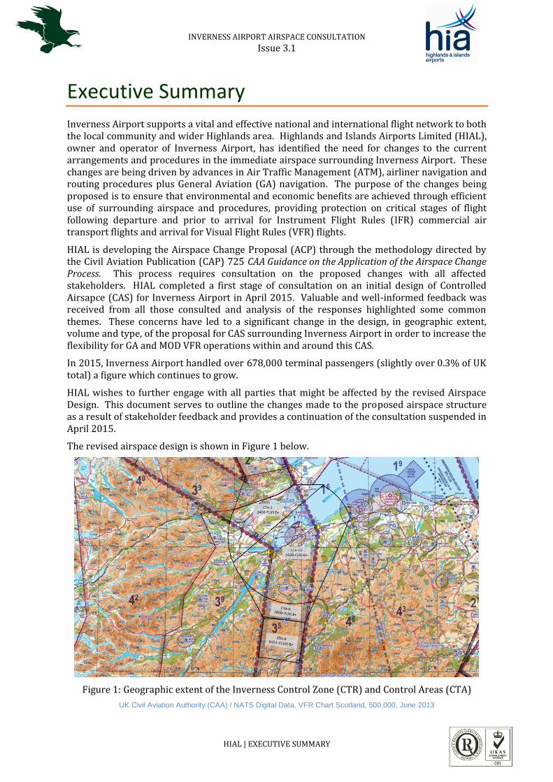
The revised airspace design is shown in Figure 1 below.
Figure 1: Geographic extent of the Inverness Control Zone (CTR) and Control Areas (CTA)
UK Civil Aviation Authority (CAA) / NATS Digital Data. VFR Chart Scotland, 500,000, June 2013

INVERNESS AIRPORT AIRSPACE CONSULTATION
The previous consultation document (7550 021 HIAL Consultation Document: Proposal for the Introduction of Controlled Airspace an Optimisation of Instrument Flight Procedures at Inverness Airport dated 19th September 2014), on thevHIAL website, provided the full background to the need for a change to the airspace classification and the new procedures HIAL intends to introduce at Inverness Airport. This document contains information from which stakeholders can gain an understanding of what changes have been made to the proposed airspace design and why, and how the new design will affect flight operations. The changes include:
Reduction in the lateral extent of the Class D airspace; Reduction in the vertical limit of the Class D Control Zone (CTR), previously from surface
to Flight Level (FL)95 (approximately 9,500 feet (ft) above mean sea level (amsl)), now surface to 2,000 ft amsl;
Reduction in the number of Class D Control Areas (CTAs) from seven to six; Reduction in the common ceiling altitude of the Class D CTAs from FL95 to 5,500 ft amsl; Increase in the number of Class E+TMZ CTAs from two to four, to be contiguous with the
Class E + TMZ airways above the Airport forming part of the UK en-route airways structure.
The consultation follows a process agreed by the UK Civil Aviation Authority (CAA) in the Civil Aviation Publication (CAP) 724, Appendix F [Reference 1]. In accordance with the guidance provided in CAP 725 [Reference 2], HIAL will consult with Aviation Stakeholders including members of the National Air Traffic Management Advisory Committee (NATMAC).
This consultation now runs from 15 August 2016 to 6 November 2016.
Please make use of the information on the HIAL website:
Inverness Airspace Change Consultation
INVERNESS AIRPORT AIRSPACE CONSULTATION
HIAL | TABLE OF CONTENTS 5
Table of Contents
Executive Summary .............................................................................................................................................................. 3
Table of Contents ................................................................................................................................................................... 5
1 Introduction .............................................................................................................................................................. 7
1.1 General ............................................................................................................................................................... 7
1.2 Background ...................................................................................................................................................... 7
1.3 Purpose and Scope ....................................................................................................................................... 7
1.4 The Document Structure ........................................................................................................................... 8
2 The Consultation Process ................................................................................................................................... 9
2.1 Overview ........................................................................................................................................................... 9
2.1.1 Consultation Topic ............................................................................................................................ 9
2.1.2 Consultation Involvement ............................................................................................................. 9
2.1.3 Method of Consultation and Response .................................................................................... 9
2.1.4 Consultation Results ....................................................................................................................... 10
2.2 Consultation CAA Oversight.................................................................................................................. 11
3 Proposal 2014 ........................................................................................................................................................ 12
3.1 Overview ......................................................................................................................................................... 12
3.2 Proposed Airspace Design 2014 .......................................................................................................... 12
4 Comments Received ............................................................................................................................................ 15
4.1 Overview ......................................................................................................................................................... 15
4.2 Issues Raised ................................................................................................................................................. 15
4.3 Addressing Concerns ................................................................................................................................. 15
5 Revised Proposal................................................................................................................................................... 16
5.1 Overview ......................................................................................................................................................... 16
5.2 Aims ................................................................................................................................................................... 16
5.3 Flight Procedures Proposal .................................................................................................................... 16
5.3.1 The Requirement............................................................................................................................... 16
5.3.2 SIDs .......................................................................................................................................................... 16
5.3.3 Transitions ........................................................................................................................................... 17
5.3.4 Final Approaches (GNSS IAPs).................................................................................................... 17
5.4 The Airspace Solution ............................................................................................................................... 17
5.4.1 Airspace Ceiling ................................................................................................................................. 17
5.4.2 Proposed Airspace Design ............................................................................................................ 18
5.4.3 Purpose of the CTR and CTAs ...................................................................................................... 21
5.5 VFR Flights and Visual Reference Points (VRP) ........................................................................... 22
5.5.1 Special VFR Flights ........................................................................................................................... 23
INVERNESS AIRPORT AIRSPACE CONSULTATION
HIAL | TABLE OF CONTENTS 6
5.5.2 Transit Flights and Visual Reference Points (VRP) .......................................................... 23
5.5.3 Secondary Surveillance Radar (SSR) Frequency Monitoring Code ........................... 24
6 Next Stages ............................................................................................................................................................... 25
6.1 Overview ......................................................................................................................................................... 25
6.2 Consultation Summary ............................................................................................................................. 25
6.3 Consultation Response ............................................................................................................................. 25
6.4 ACP – Moving Forward ............................................................................................................................. 25
References ............................................................................................................................................................................... 26
Annex A – Glossary of Terms ......................................................................................................................................... A1
Annex B – Draft IAP Approach Plates ........................................................................................................................ B1
Annex C – Proposed CTR/A Data .................................................................................................................................. C1
Annex D – VRP List ............................................................................................................................................................. D1
INVERNESS AIRPORT AIRSPACE CONSULTATION
HIAL | INTRODUCTION 7
1 Introduction
1.1 General
HIAL, owner and operator of Inverness Airport, identified some time ago the need for changes to the current arrangements and procedures in the immediate airspace surrounding the Airport. The purpose of such changes is to ensure that environmental and economic benefits are achieved through efficient use of surrounding airspace and consequently that current efficiency and effectiveness is preserved for all aircraft, providing protection on critical stages of flight following departure and prior to arrival for commercial air transport flights, and arrival for Visual Flight Rules (VFR) flights.
In 2015, Inverness Airport handled over 678,000 terminal passengers (just over 0.3% of UK total)1 and plays a crucial role in supporting economic growth and prosperity, particularly in The Highlands; for business, international trade and leisure, flying is central to today’s fast-moving lifestyle. The Airport supports a vital and effective national and international flight network for both the local community and wider Highlands area and the number of commercial air transport movements (atm) is expected to continue to grow
Updating the airspace design gives HIAL the opportunity to improve airspace efficiency (through proactive, rather than reactive, air traffic management (ATM)), and better match the airspace and procedures therein to the improved performance capabilities of more modern aircraft. The net effect of these proposals would be to enhance the overall efficiency of airspace management for Inverness Airport Air Traffic Control (ATC), and to achieve connectivity to the wider air route network. This document outlines the proposals from HIAL for the enhancement of Inverness Airport’s procedures and the establishment of appropriate airspace, to benefit both operators and the local community.
1.2 Background
In order to introduce a change to airspace arrangements, the process outlined in Civil Aviation Publication (CAP) 725 [Reference 2] must be followed. This requires a period of consultation on the proposed changes with all affected stakeholders. HIAL undertook an initial phase of consultation, which closed in April 2015. This consultation produced feedback from which a strong theme emerged; restriction of VFR operations. In order to minimise any adverse impact to VFR operations for both General Aviation and military aircraft, the airspace was re-designed. Such an extensive change to the proposal requires a further period of consultation.
1.3 Purpose and Scope
This document provides a continuation of the consultation process undertaken by HIAL and details the revised airspace design, outlining the changes and the rationale for them. The purpose of this document is to enable stakeholder engagement and response to HIAL’s proposal within the defined consultation period. Contact details for responses and further enquiries are provided along with the response deadline.
1 CAA UK Airport Statistics www.caa.co.uk
INVERNESS AIRPORT AIRSPACE CONSULTATION
HIAL | INTRODUCTION 8
1.4 The Document Structure
This document is divided into seven main Sections and six annexes as outlined below for your convenience:
Section 1 introduces the document;
Section 2 provides an overview of the consultation process;
Section 3 provides an overview of the proposal that was previously consulted on;
Section 4 details the concerns highlighted during consultation and how they have been
addressed;
Section 5 details the revised design and procedures now being proposed;
Section 6 provides a summary and information on the next stages of consultation.
References are provided following Section 6.
There are four Annexes:
Annex A provides a Glossary of Terms;
Annex B provides the Draft IAP Plates;
Annex C provides the proposed CTR/A data; and
Annex D provides the VRP data.
INVERNESS AIRPORT AIRSPACE CONSULTATION
HIAL | THE CONSULTATION PROCESS 9
2 The Consultation Process
2.1 Overview
HIAL wish to further engage with all parties that might be affected by its revised proposed Airspace Change. Constructive feedback will inform the Proposal development, ensuring further positive effects are enhanced and negative impact is minimised. This also meets the CAA mandatory requirement to undertake stakeholder consultation, a continuation from that conducted in late 2014 and early 2015, as part of the submission of an Airspace Change Proposal. . This Section provides a brief overview of the consultation process for HIAL’s proposal at Inverness Airport.
2.1.1 Consultation Topic
This consultation is about a proposal to establish Controlled Airspace (CAS), Class D2 and Class E3+Transponder Mandatory Zone (TMZ)4, surrounding Inverness Airport. The proposed design has changed as a result of stakeholder feedback from the consultation held 2014/2015. This consultation considers the new airspace design and, for true transparency, also provides information on new satellite-based approach procedures (which replicate the current runway final approach paths) that will be introduced coincident with the change to the airspace.
This consultation is not about:
Inverness Airport future development or aspects of Government Aviation Policy; Noise Abatement Procedures for departing aircraft or Noise Preferential Routes; Consultation on the Implementation of Commission Implementing Regulation (EU) No
923/2012 of 26 September 2012, Standardised European Rules of the Air (SERA) in the United Kingdom.
This consultation is also not about the Consultation on the Implementation of Commission Implementing Regulation (EU) No 923/2012 of 26 September 2012, SERA in the United Kingdom. The status of this consultation can be viewed at SERA Consultation. HIAL will note any comments on this issue included in your responses but they will not be considered further the Inverness Airport airspace change analysis.
2.1.2 Consultation Involvement
All parties affected are invited to submit comments on the revised proposal, regardless of whether they submitted comment during the first period of consultation. The stakeholder community is unchanged from the initial consultation; views and opinions from aviation and non-aviation parties alike will be sought.
2.1.3 Method of Consultation and Response
The consultation document can be viewed on and downloaded from the HIAL website (Inverness Airspace Change Consultation). The additional period of consultation on the revised
2 Class D airspace cannot be entered without Air Traffic Control (ATC) clearance and an air traffic service is mandatory. Class D is the most common airspace class established for the protection of airports in the UK, mainly consisting of CTRs and CTAs (CTR/A). 3 Class E airspace cannot be entered by IFR traffic without Air Traffic Control (ATC) clearance, VFR traffic does not require a clearance; however, pilots are encouraged to contact ATC and comply with instructions. 4 A TMZ is airspace of defined dimensions wherein aircraft wishing to enter or fly within the defined area, will be required to have and operate Secondary Surveillance Radar (SSR) equipment or receive ATC clearance to enter.
INVERNESS AIRPORT AIRSPACE CONSULTATION
HIAL | THE CONSULTATION PROCESS 10
proposal is 10 weeks, commencing on 15 August 2016 and closing on 6 November 2016. All consultation responses should be submitted to HIAL, using the email address ([email protected]) on the Inverness Airspace Change Consultation webpage where further information is available.
The email responses should include ‘Inverness CAS’ in the email subject line with suggested content as follows:
First line of text:
“I am responding on behalf of [name of organisation/local council]”
or “I am responding as a member of the public”
Second line of text:
[Agreement to pass on personal details to the CAA, for Data Protection Act compliance]:
“I/We agree/do not agree that personal details contained within this response may be sent to the CAA as part of the Airspace Change Proposal”
Third line of text:
Your formal response, one of the following:
“I/We support the addition of Inverness Airport’s Controlled Airspace”,
“I/We have no objection to the addition of Inverness Airport’s Controlled Airspace”
Or “I/We object to the addition of Inverness Airport’s Controlled Airspace”
Subsequent text:
Please state the reasons for your response, (the reasons why you support or object to, the proposal).
For the consultation to be effective it is essential for consultees to be able to express their relevant viewpoints and therefore HIAL Management kindly ask for responses to be submitted in a timely manner.
Written responses can be made to Inverness Airspace Change, HIAL, Inverness Airport, Inverness, Scotland, IV2 7JB.
Where a consultee requires a clarification or has an additional query, please make it clear that the request is for further information in the email subject line.
2.1.4 Consultation Results
All consultee responses received by HIAL will be recorded prior to consultation closure on 6th November 2016. HIAL may contact consultees if response clarification or additional information is required. Following the closure deadline, all responses will be analysed. Feedback for consultees on the responses received and the decision on the final proposal option selected will be published on the HIAL website. A Consultation Report will highlight the key themes that arose and how HIAL will incorporate those issues into its airspace change proposal.
The CAA requires that all consultation material, including copies of responses from consultees and others, are included in any formal submission to the CAA for an Airspace Change Proposal. In order to provide a meaningful response, we need to know your name, home address or business address. All the feedback from the consultation will be made available to the CAA as part of our airspace change proposal. This will allow the CAA to assess independently whether HIAL have drawn appropriate conclusions in the development of the proposed design.
INVERNESS AIRPORT AIRSPACE CONSULTATION
HIAL | THE CONSULTATION PROCESS 11
Responses will be treated with due care and sensitivity by HIAL, by the consultation specialists, and by the CAA. Apart from the CAA, HIAL undertake not to disclose personal data to any other party without prior permission.
2.2 Consultation CAA Oversight
The consultation process for the Inverness Airport airspace change is managed by HIAL, in compliance with CAP725 [Reference 2]. In the case of complaints relating to the adherence of HIAL to the consultation process, CAA Airspace Regulation (AR) is to be contacted by the details below. Please note; the CAA is responsible for overseeing the consultation process only and will therefore not comment on the proposed changes.
Airspace Business Coordinator Airspace, ATM and Aerodromes CAA House 45-59 Kingsway London WC2B 6TE E-mail: [email protected]
INVERNESS AIRPORT AIRSPACE CONSULTATION
HIAL | PROPOSAL 2014 12
3 Proposal 2014
3.1 Overview
This consultation is a continuation of that held in late 2014 and early 2015. The revised design takes into account comments received during that consultation. In order to assess the changes made since the first consultation, a summary of the original proposal is provided below.
3.2 Proposed Airspace Design 2014
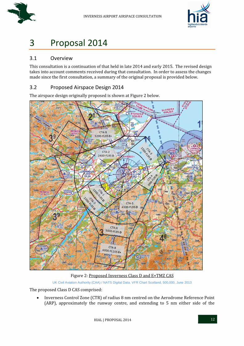
The airspace design originally proposed is shown at Figure 2 below.
Figure 2: Proposed Inverness Class D and E+TMZ CAS
UK Civil Aviation Authority (CAA) / NATS Digital Data. VFR Chart Scotland, 500,000, June 2013
The proposed Class D CAS comprised:
Inverness Control Zone (CTR) of radius 8 nm centred on the Aerodrome Reference Point (ARP), approximately the runway centre, and extending to 5 nm either side of the
INVERNESS AIRPORT AIRSPACE CONSULTATION
HIAL | PROPOSAL 2014 13
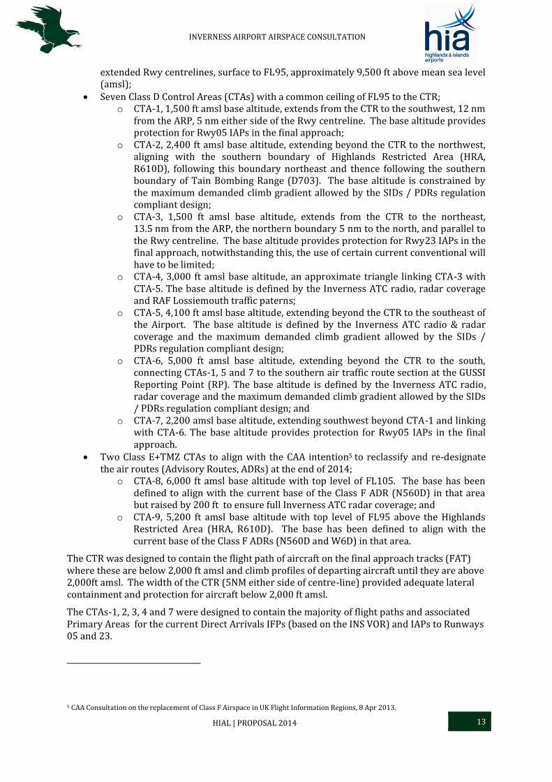
extended Rwy centrelines, surface to FL95, approximately 9,500 ft above mean sea level (amsl);
Seven Class D Control Areas (CTAs) with a common ceiling of FL95 to the CTR; o CTA-1, 1,500 ft amsl base altitude, extends from the CTR to the southwest, 12 nm
from the ARP, 5 nm either side of the Rwy centreline. The base altitude provides protection for Rwy05 IAPs in the final approach;
o CTA-2, 2,400 ft amsl base altitude, extending beyond the CTR to the northwest, aligning with the southern boundary of Highlands Restricted Area (HRA, R610D), following this boundary northeast and thence following the southern boundary of Tain Bombing Range (D703). The base altitude is constrained by the maximum demanded climb gradient allowed by the SIDs / PDRs regulation compliant design;
o CTA-3, 1,500 ft amsl base altitude, extends from the CTR to the northeast, 13.5 nm from the ARP, the northern boundary 5 nm to the north, and parallel to the Rwy centreline. The base altitude provides protection for Rwy23 IAPs in the final approach, notwithstanding this, the use of certain current conventional will have to be limited;
o CTA-4, 3,000 ft amsl base altitude, an approximate triangle linking CTA-3 with CTA-5. The base altitude is defined by the Inverness ATC radio, radar coverage and RAF Lossiemouth traffic paterns;
o CTA-5, 4,100 ft amsl base altitude, extending beyond the CTR to the southeast of the Airport. The base altitude is defined by the Inverness ATC radio & radar coverage and the maximum demanded climb gradient allowed by the SIDs / PDRs regulation compliant design;
o CTA-6, 5,000 ft amsl base altitude, extending beyond the CTR to the south, connecting CTAs-1, 5 and 7 to the southern air traffic route section at the GUSSI Reporting Point (RP). The base altitude is defined by the Inverness ATC radio, radar coverage and the maximum demanded climb gradient allowed by the SIDs / PDRs regulation compliant design; and
o CTA-7, 2,200 amsl base altitude, extending southwest beyond CTA-1 and linking with CTA-6. The base altitude provides protection for Rwy05 IAPs in the final approach.
Two Class E+TMZ CTAs to align with the CAA intention5 to reclassify and re-designate the air routes (Advisory Routes, ADRs) at the end of 2014;
o CTA-8, 6,000 ft amsl base altitude with top level of FL105. The base has been defined to align with the current base of the Class F ADR (N560D) in that area but raised by 200 ft to ensure full Inverness ATC radar coverage; and
o CTA-9, 5,200 ft amsl base altitude with top level of FL95 above the Highlands Restricted Area (HRA, R610D). The base has been defined to align with the current base of the Class F ADRs (N560D and W6D) in that area.
The CTR was designed to contain the flight path of aircraft on the final approach tracks (FAT) where these are below 2,000 ft amsl and climb profiles of departing aircraft until they are above 2,000ft amsl. The width of the CTR (5NM either side of centre-line) provided adequate lateral containment and protection for aircraft below 2,000 ft amsl.
The CTAs-1, 2, 3, 4 and 7 were designed to contain the majority of flight paths and associated Primary Areas for the current Direct Arrivals IFPs (based on the INS VOR) and IAPs to Runways 05 and 23.
5 CAA Consultation on the replacement of Class F Airspace in UK Flight Information Regions, 8 Apr 2013.
INVERNESS AIRPORT AIRSPACE CONSULTATION
HIAL | PROPOSAL 2014 14
The design of CTAs-4, 5, 6 and 7 was intended to contain the flight paths and associated Primary Areas6 for the proposed Preferred Departure Routes (PDRs) and Preferred Arrival Routes (PARs), providing connectivity to the air routes through the Class E + TMZ CTAs-8 and 9.
6 Primary Areas constructed in accordance with ICAO Doc 8168 Vol are associated volumes of airspace protected by CAS or from physical intrusion and obstruction (CAP725).
INVERNESS AIRPORT AIRSPACE CONSULTATION
HIAL | COMMENTS RECEIVED 15
4 Comments Received
4.1 Overview
Comments received during the first consultation period led to further discussions with Ministry of Defence (MoD) and local aviation stakeholders. As a result, significant changes have been made to the design (in geographic extent, volume and type) of the proposal for Inverness Airport CAS. The change has increased the flexibility for VFR operations, both for GA and the MoD, within and around the designed CAS and increased the integrity of information readily available to VFR aircraft commanders in ‘two-way’, air-ground, radio contact with Inverness Airport Air Traffic Control (ATC).
4.2 Issues Raised
The Airport undertook an extensive period of consultation and further discussion in order to gain an understanding of airspace user groups’ concerns and to take into account ideas and suggestions to accommodate all stakeholder needs within the early designs. Despite the structure and classification of the airspace being designed to allow access by all classes of aircraft (including, by arrangement, non-radio operators) concerns arose from elements of the GA, Sports and Recreation airspace user community, including the Light Aircraft Association Highland & Islands Strut, flying schools and individual aviators. The concerns were based upon the perceived curtailment of their freedom of airspace access, particularly during periods of poor visibility at Inverness Airport, and airspace utility. The dimensions of the CAS were carefully considered in response to these concerns.
4.3 Addressing Concerns
In some areas, it has not been possible to reduce substantially the lateral dimensions of the proposed CTAs, but it has been possible to change the classification and vertical dimensions, predominantly aimed at increasing VFR access, with transponder carriage, to the CAS.
A detailed review of the initial concepts, held in conjunction with the RAF Lossiemouth Operations Wing and Tain Range Control resulted in a further reduction in the overall volume of CAS required. Primarily, this has been achieved by removing CTA-9 above EG R610D. Extensive use of Class E + TMZ airspace for CTAs-2, 6, 8 and 10 has significantly increased flexibility for VFR operations above 5,500 ft within the designed Inverness Airport CAS. The inclusion of the Class D CTA-11 above a ‘capped’ CTR of ceiling 2,000 ft has increased VFR flexibility in poor weather conditions at the Airport. Furthermore, the change to Class E + TMZ airspace in CTAs-2 and 6 has mitigated the concerns regarding VFR, Class G ‘head room’ between the base of these CTAs and the underlying terrain and VFR operations from GA aerodromes near or underneath these CTAs.
INVERNESS AIRPORT AIRSPACE CONSULTATION
HIAL | REVISED PROPOSAL 16
5 Revised Proposal
5.1 Overview
The design of CAS is a careful balance between the competing needs of all of the various airspace users and must also take into account the environmental impact of the aircraft operations whilst maintaining safe operations. Following comments received during the first consultation period, extensive changes have been made to the airspace proposed for introduction surrounding Inverness Airport. This section provides full details of the current proposed airspace and procedures.
5.2 Aims
The overall aim of the Inverness Airport Airspace Change Proposal is to enhance effectiveness and improve the efficiency of Inverness Airport’s operations whilst minimising adverse effects to General Air Traffic (GAT) and the environment. The proposed designs will achieve this through:
The introduction of optimal arrival and departure routes improving efficiency whilst reducing the noise impact of arriving and departing airliners;
The introduction of Continuous Descent Approaches (CDAs) and Continuous Climb Departures (CCDs) to reduce environmental impact through reductions in fuel emissions through the establishment of IFPs which incorporate the use of new technical navigational developments through Satellite-Based Augmentation Systems (SBAS);
The establishment of IAPs (Global Navigation Satellite System (GNSS) final approaches) which incorporate the use of new technical navigational developments through SBAS;
The design of airspace to adequately contain these IFPs, provide national route connectivity and provide protection for all aircraft operating near Inverness Airport whilst improving flexibility away from the Airport’s immediate vicinity.
5.3 Flight Procedures Proposal
5.3.1 The Requirement
The Inverness Airport VOR (INS) is due to be withdrawn in 2019 under the NATS VOR Rationalisation and Replacement Programme. This will result in the loss of the primary Inverness Airport arrival and departure aid. It is therefore intended to introduce Area Navigation (RNAV) GNSS Instrument Approach Procedures (IAPs), which replicate the current final approach tracks, coincident with the implementation of the airspace change. Instrument Flight Procedures (IFPs), founded on the technological advancements of RNAV and Required Navigation Performance (RNP) through Performance Based Navigation (PBN), are needed to link to these IAPs. To allow transition from ground-based navigation to satellite-based navigation, Preferred Arrival Routes (PAR or Transitions) and Preferred Departure Routes (PAR or Standard Instrument Departures (SIDs)) are required.
5.3.2 SIDs
It is intended to introduce a set of three Standard Instrument Departures (SIDs) for each runway. These routes accommodate departures as direct as possible, taking into account underlying terrain and urban areas, to each of the three exit air routes, one to Glasgow and one each to the northern and western isles. The design of the departure routes provides more direct flight, therefore reducing the overall flown track miles and reducing fuel emissions. In addition, this should decrease the inherent noise footprint with benefits to the Airport’s local community.
INVERNESS AIRPORT AIRSPACE CONSULTATION
HIAL | REVISED PROPOSAL 17
The PDRs incorporate CCDs to reduce further the environmental impact through minimal fuel burn during the climb into the ATS en-route system. Additional routings were also considered, but HIAL studied departure statistics and discarded probable low frequency departure routes in order to minimise the impact on other airspace users. The draft SID plates are shown, for clarity and to enhance detail, on the Inverness Airspace Change webpage; these routes are unchanged from those proposed in the consultation of 2014/15.
5.3.3 Transitions
It is intended to introduce a set of three Transitions for each runway. These routes accommodate arrivals as direct as possible. The PARs take into account underlying terrain and urban areas, without the requirement for a procedural hold (further reducing fuel burn), to the runway in use from each of the three entry air routes from Glasgow and the isles. The design of these arrival routes provides more direct flight, therefore reducing the overall flown track miles and reducing fuel emissions. In addition, this should decrease the inherent noise footprint with benefits to the Airport’s local community. These routes also take advantage of CDAs leading to further environmental benefits, as fuel emissions are reduced in the descent to the runway. Additionally, the arrival routes are designed to take advantage of new technological developments in RNAV through PBN; this will future-proof the procedures at Inverness Airport and ensure compliance with National and International Air Management Programmes. The PARs can be flown by conventional means but provide for the anticipated aircraft navigational equipment upgrades to accommodate RNAV procedures. The draft Arrival (Transitions) plates are shown, for clarity and to enhance detail, on the Inverness Airspace Change webpage; these routes are unchanged from those proposed in the consultation of 2014/15.
5.3.4 Final Approaches (GNSS IAPs)
Approach Applications which are classified as RNP Approach (APCH) in accordance with ICAO Doc 9613 Performance Based Navigation (PBN) Manual (and ICAO state Letter SP 65/4-10/53) give access to minima (on an Instrument Approach Procedure) for all suitably equipped aircraft. The instrument approach procedures associated with RNP APCH are entitled RNAV (GNSS) to reflect that GNSS is the primary navigation system. With the inherent onboard performance monitoring and alerting provided by GNSS, the navigation specification qualifies as RNP, however these procedures pre-date PBN, so the chart name has remained as RNAV. These types of RNAV (GNSS) are being introduced by HIAL at Inverness Airport in 2017. The draft IAP plates are shown at Annex B & individually in detail on the Inverness Airspace Change webpage.
5.4 The Airspace Solution
5.4.1 Airspace Ceiling
The high ground surrounding Inverness Airport means that the Airport has the highest minimum terrain safe levels in the UK. The minimum level available is weather dependent, but it is common for the minimum terrain safe level to be FL65 or FL70. A proposed airspace ceiling of FL95 allows vertical separation of three aircraft, a traffic level experienced daily, between Commercial Air Traffic (CAT) inbound to Inverness Airport and CAT in the above airways structure (FL95-105). A lower ceiling would lead to a ‘gap’ between the en-route structure above the Airport and its CTR/A providing challenging ATM procedures and processes to Inverness Airport ATC as CAT cross into and out of CAS within a very short period. A lower ceiling would also lead to frequent problems of insufficient allocation levels for aircraft prior to the establishment of alternative separation in arrival or departure. This would result in extra co-ordination with adjacent units, a consequential increase in controller workload, undesirable economic and environmental impact as efficiency is impacted and delays begin to accumulate. Furthermore, with a low ceiling, it is likely that high performance departing airliners will need
INVERNESS AIRPORT AIRSPACE CONSULTATION
HIAL | REVISED PROPOSAL 18
to level off to remain inside the CAS before they have climbed through the level of an inbound airliner or slower outbound aircraft incurring additional economic and environmental penalties.
The ceiling of the proposed CAS is FL95 and FL105 (approximately 9,500ft and 10,500 ft); HIAL propose that RAF Lossiemouth has coordinated entry to the proposed CAS. This has been discussed with the MoD and accepted in principle, and will subsequently be placed in a Tripartite LoA. This will also facilitate uninhibited, day-to-day, planned fast jet access to the Tain Range for medium level close air support training. Flexible use of the airspace is essential and this aspect will be invisible to CAT and GAT, so full details are unlikely to be published within the UK IAIP.
5.4.2 Proposed Airspace Design
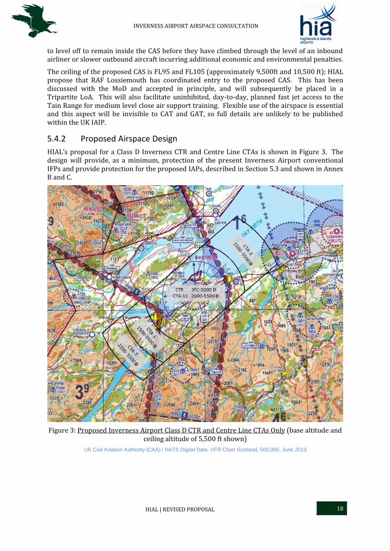
HIAL’s proposal for a Class D Inverness CTR and Centre Line CTAs is shown in Figure 3. The design will provide, as a minimum, protection of the present Inverness Airport conventional IFPs and provide protection for the proposed IAPs, described in Section 5.3 and shown in Annex B and C.
Figure 3: Proposed Inverness Airport Class D CTR and Centre Line CTAs Only (base altitude and ceiling altitude of 5,500 ft shown)
UK Civil Aviation Authority (CAA) / NATS Digital Data. VFR Chart Scotland, 500,000, June 2013

INVERNESS AIRPORT AIRSPACE CONSULTATION
HIAL | REVISED PROPOSAL 19
The establishment of Class D airspace surrounding Inverness Airport would require pilot clearance from Inverness Airport ATC before entering; satisfying the requirements for an abbreviated7 VFR Flight Plan (FPL) in CAS. The establishment of supplementary Class E + TMZ airspace surrounding Inverness Airport Class D would not require pilot clearance, when the aircraft is carrying an operating transponder, before entering. The combination of both types of airspace in an Inverness Airport CAS proposal would provide a ‘better known’, safe traffic environment with expeditious and efficient traffic management of all aircraft, general and commercial with capacity and flexibility for future technological advances in ATM.
The limit of the CTR ceiling to 2,000 ft allows greater flexibility for VFR operations above the Airport, reducing the requirements for a Special VFR clearance when crossing the Airport’s CAS, particularly when the reported visibility in the Airport’s CTR8 is reduced.
It is proposed that the CTR/As and ATZ are active during the published hours of the Airport to cover the day and night commercial operation as currently published.
Outside the published hours the airspace would revert to Class G and the ATZ removed. The Transition Altitude (TA) within the proposed Inverness CTR/A will be 6,000 ft, in line with the present CAA policy for TA within CAS [Reference 3].
The proposed CAS, shown within Figure 4, comprises:
Class D Inverness Control Zone (CTR) of radius 8 nm centred on the Aerodrome Reference Point (ARP), approximately the runway centre, and extending to 5 nm either side of the extended Rwy centrelines, surface to 2,000 ft above mean sea level (amsl);
Six Class D Control Areas (CTAs) with a common ceiling of 5,500 ft; o CTA-1, 1,500 ft amsl base altitude, extends from the CTR to the southwest, 12 nm
from the ARP, 5 nm either side of the Rwy centreline. The base altitude provides protection for Rwy05 IAPs in the final approach;
o CTA-3, 1,500 ft amsl base altitude, extends from the CTR to the northeast, 13.5 nm from the ARP, the northern boundary 5 nm to the north, and parallel to the Rwy centreline. The base altitude provides protection for Rwy23 IAPs in the final approach, notwithstanding this, the use of certain current conventional procedures will have to be limited;
o CTA-4, 3,000 ft amsl base altitude, an approximate triangle linking CTA-3 with CTA-5. The base altitude is defined by the Inverness Airport ATC radio and radar coverage and RAF Lossiemouth traffic patterns;
o CTA-5, 4,100 ft amsl base altitude, extending beyond the CTR to the southeast of the Airport. The base altitude is defined by the Inverness Airport ATC radio and radar coverage and the maximum demanded climb gradient allowed by the SIDs / PDRs regulation compliant design; and
o CTA-7, 2,200 amsl base altitude, extending southwest beyond CTA-1 and linking with CTA-6. The base altitude provides protection for Rwy05 IAPs in the final approach;
o CTA-11, 2,000 ft amsl base altitude;
7 A Flight Plan (FPL) is required for flights in all CAS except Class E. In certain circumstances the FPL requirement may be satisfied by passing flight details on air-ground, radio contact. An abbreviated FPL comprises sufficient information to enable an ATC Unit to issue a clearance and for search and rescue purposes (Rule 29 of UK Air Navigation Order). An ATC Clearance is required for flight in all CAS except Class E 8 For the purpose of taking off or landing within a CTR, the actual meteorological visibility reported by ATC shall be taken as the flight visibility. (Rule 26 of the UK Air Navigation Order). ATC will not issue a Special VFR clearance to any fixed wing aircraft intending to depart from an aerodrome in a CTR when the official meteorological report indicates that the visibility is 1800 m or less and/or the cloud ceiling is less than 600 ft
INVERNESS AIRPORT AIRSPACE CONSULTATION
HIAL | REVISED PROPOSAL 20
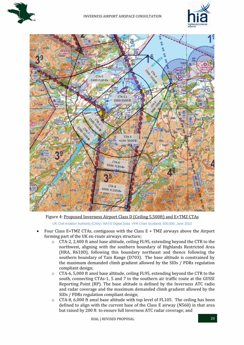
Figure 4: Proposed Inverness Airport Class D (Ceiling 5,500ft) and E+TMZ CTAs
UK Civil Aviation Authority (CAA) / NATS Digital Data. VFR Chart Scotland, 500,000, June 2013
Four Class E+TMZ CTAs, contiguous with the Class E + TMZ airways above the Airport forming part of the UK en-route airways structure;
o CTA-2, 2,400 ft amsl base altitude, ceiling FL95, extending beyond the CTR to the northwest, aligning with the southern boundary of Highlands Restricted Area (HRA, R610D), following this boundary northeast and thence following the southern boundary of Tain Range (D703). The base altitude is constrained by the maximum demanded climb gradient allowed by the SIDs / PDRs regulation compliant design;
o CTA-6, 5,000 ft amsl base altitude, ceiling FL95, extending beyond the CTR to the south, connecting CTAs-1, 5 and 7 to the southern air traffic route at the GUSSI Reporting Point (RP). The base altitude is defined by the Inverness ATC radio and radar coverage and the maximum demanded climb gradient allowed by the SIDs / PDRs regulation compliant design;
o CTA-8, 6,000 ft amsl base altitude with top level of FL105. The ceiling has been defined to align with the current base of the Class E airway (N560) in that area but raised by 200 ft to ensure full Inverness ATC radar coverage; and
INVERNESS AIRPORT AIRSPACE CONSULTATION
HIAL | REVISED PROPOSAL 21
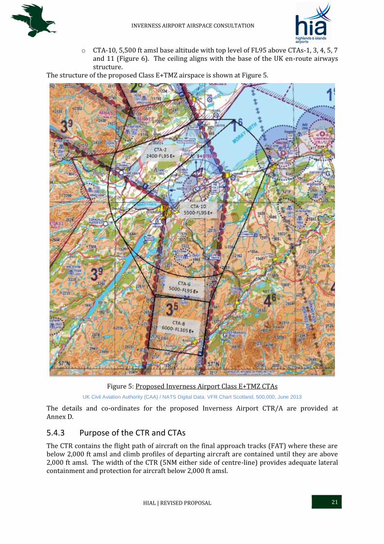
o CTA-10, 5,500 ft amsl base altitude with top level of FL95 above CTAs-1, 3, 4, 5, 7 and 11 (Figure 6). The ceiling aligns with the base of the UK en-route airways structure.
The structure of the proposed Class E+TMZ airspace is shown at Figure 5.
Figure 5: Proposed Inverness Airport Class E+TMZ CTAs
UK Civil Aviation Authority (CAA) / NATS Digital Data. VFR Chart Scotland, 500,000, June 2013
The details and co-ordinates for the proposed Inverness Airport CTR/A are provided at Annex D.
5.4.3 Purpose of the CTR and CTAs
The CTR contains the flight path of aircraft on the final approach tracks (FAT) where these are below 2,000 ft amsl and climb profiles of departing aircraft are contained until they are above 2,000 ft amsl. The width of the CTR (5NM either side of centre-line) provides adequate lateral containment and protection for aircraft below 2,000 ft amsl.
INVERNESS AIRPORT AIRSPACE CONSULTATION
HIAL | REVISED PROPOSAL 22
The CTAs-1, 2, 3, 4 and 7 contain the majority of flight paths and associated Primary Areas for the current Direct Arrivals IFPs (based on the INS VOR) and IAPs to Runways 05 and 23.
The CTAs-4, 5, 6 and 7 contain the flight paths and associated Primary Areas for the proposed PDRs and PARs (depicted at Annex B) providing connectivity to the air routes through the Class E + TMZ CTAs-8 and 11.
5.5 VFR Flights and Visual Reference Points (VRP)
HIAL wish to make as little impact as is practicable on the extant operation of VFR flights at and near Inverness Airport, including operations to and from nearby aerodromes. Inverness ATC does not envisage any capacity problems in integrating VFR flights, including transit flights, into the proposed CTR/A traffic flow.
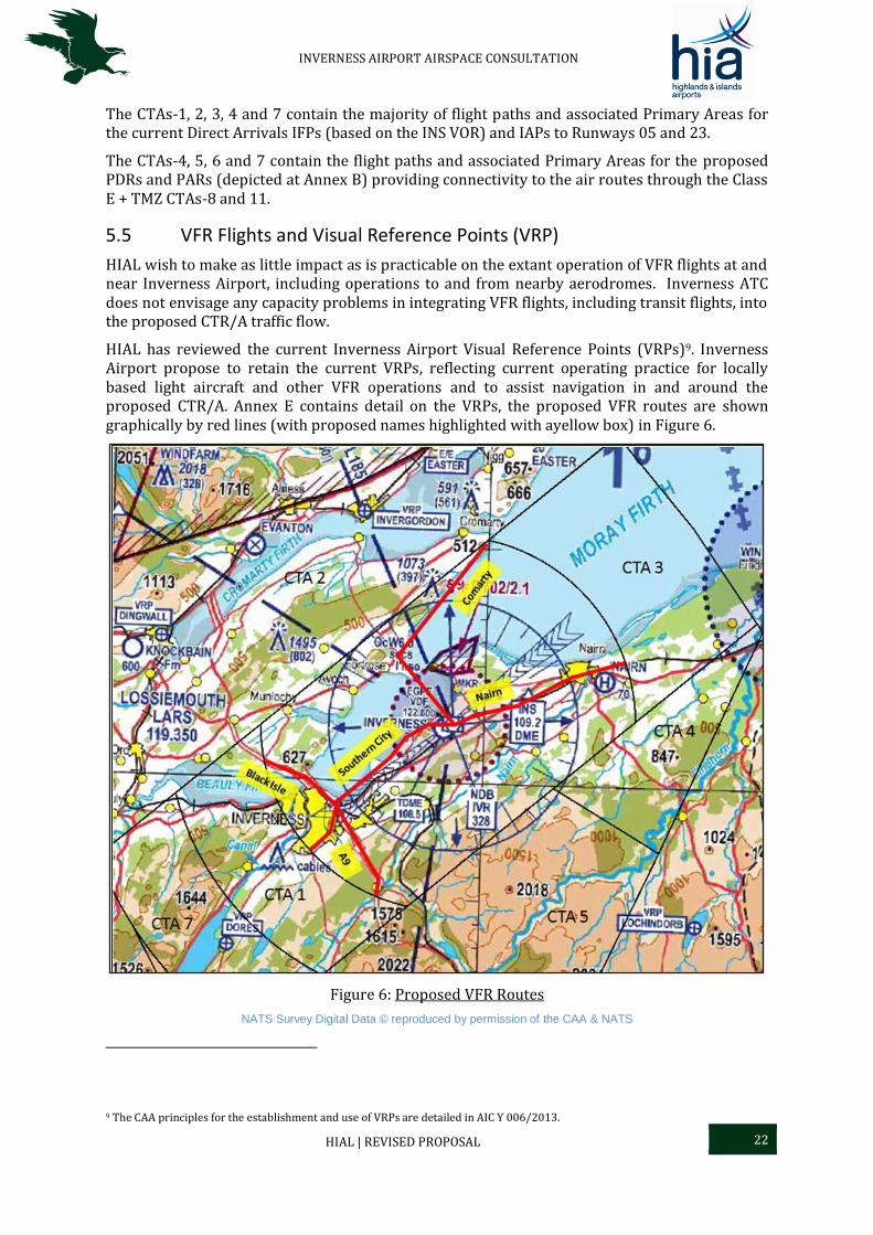
HIAL has reviewed the current Inverness Airport Visual Reference Points (VRPs)9. Inverness Airport propose to retain the current VRPs, reflecting current operating practice for locally based light aircraft and other VFR operations and to assist navigation in and around the proposed CTR/A. Annex E contains detail on the VRPs, the proposed VFR routes are shown graphically by red lines (with proposed names highlighted with ayellow box) in Figure 6.
Figure 6: Proposed VFR Routes
NATS Survey Digital Data © reproduced by permission of the CAA & NATS
9 The CAA principles for the establishment and use of VRPs are detailed in AIC Y 006/2013.

INVERNESS AIRPORT AIRSPACE CONSULTATION
HIAL | REVISED PROPOSAL 23
Inbound and outbound routings/clearances to and from Inverness Airport would utilise the current VRPs and proposed VFR routes although, whenever practicable, direct routing will be approved. A local Light Aircraft Association (LAA) and Highland & Islands Strut10 member has visually checked the current VRPs from the air for suitability, both day and night, and convenient location with regard to the CTR VFR routes.
5.5.1 Special VFR Flights
Special VFR (SVFR) clearances are applicable only within control zones and under conditions which would usually require aircraft to comply with IFR (i.e. in IMC or at night). Within the proposed airspace, this would be in the Inverness Airport CTR, airspace below 2,000 ft. They are normally available to those types of light aircraft operations which are conducted with visual reference to the ground11. HIAL has considered the current SERA Implementing Regulation12 and understands that, as presently proposed, SERA will change the VFR access requirements to Class D CTRs13. SVFR clearances require standard IFR separation both between two SVFR flights, and between SVFR and IFR flights. HIAL proposes to establish visually referenced Clearance Limits for inbound SVFR flights (including PDG helicopter operations), which will provide adequate geographical separation, in accordance with MATS Part 1, for the purposes of IFR separation in time or space, from Final Approach and Departure tracks. The routing within the CTR to the SVFR clearance limits will normally be with reference to the current VRPs (Figure 6) and proposed VFR routes.
The pilot shall determine the flight meteorological conditions under which s/he intends to operate. Currently for flights in Class D control zones the pilot is required to take the reported meteorological visibility for the aerodrome (as passed by ATC) as being the flight visibility and conduct her/his flight accordingly14. This requirement, and changes in SERA, dictated the decision to limit the ceiling of the Inverness Airport CTR to 2,000 ft allowing pilots flying in the proposed Inverness Airport CAS above 2,000 ft greater flexibility when ground visibility15 is less than the VMC minimum.
5.5.2 Transit Flights and Visual Reference Points (VRP)
Transit flights through the proposed Inverness CTR, by both VFR and IFR, will be accommodated on direct routings to the maximum extent practicable. Exceptionally it may be necessary to specify ATC clearance with reference to the notified VRPs, or by radar vectoring, or refuse transit clearance through the CTR/A. HIAL expects that refusals are only likely in exceptional circumstances.
Aircraft crossing the Class E+TMZ CTAs under VFR would not require a clearance to cross if they are carrying and operating a suitable SSR transponder. Aircraft crossing Class E+TMZ CTAs under VFR without a functioning suitable SSR transponder would normally be required to be in ‘two-way’, air-ground radio contact with the controlling authority and require a clearance to
10 The Highland & Islands Strut of the Light Aircraft Association is a membership of pilots and enthusiasts living mainly in the Highlands & Islands region of Scotland. 11 Rules for SVFR flights are detailed in the UK AIP (ENR 1-2-1, paragraph 2). 12 No 923/2012. 13 CAA & SERA 14 For the purpose of taking off or landing within a CTR, the actual meteorological visibility reported by ATC shall be taken as the flight visibility. (Rule 26 of the UK Air Navigation Order). ATC will not issue a Special VFR clearance to any fixed wing aircraft intending to depart from an aerodrome in a CTR when the official meteorological report indicates that the visibility is 1800 m or less and/or the cloud ceiling is less than 600 ft 15 ‘ground visibility’ means the visibility at an aerodrome, as reported by an accredited observer or by automatic systems.

INVERNESS AIRPORT AIRSPACE CONSULTATION
HIAL | REVISED PROPOSAL 24
cross. In accordance with published crossing procedures appropriate arrangements for non-radio access will be developed for Feshiebridge and Easterton glider operations.
A number of paraglider and hang-glider operations take place routinely near Inverness Airport from Alturlie Point. HIAL intends to accommodate such flights to the maximum extent practicable within the proposed Inverness CTR/A, subject to prior co-ordination with Inverness ATC. The capability for ‘two-way’, air-ground radio communication with Inverness ATC would be a distinct advantage to such accommodation. An LoA is in draft between Inverness ATC and the operators at Alturlie Point site to enhance mixed CAT and GA paraglider operations in this area.
5.5.3 Secondary Surveillance Radar (SSR) Frequency Monitoring Code
The introduction of an Inverness Airport SSR Frequency Monitoring Code16 Procedure, along with the use of VRPs, is likely to reduce significantly the volume of RT traffic, and increase controller capacity, particularly with GAT. Pilots who have no intention of entering the CAS CTR/As do not have to contact Inverness Airport ATC on air-ground radio to advise of their proximity to the CTR/A; pilots can select the monitoring squawk to demonstrate they can be contacted if necessary, but do not require an ATS and will remain outside CAS. Inverness Airport ATS will continue to be available to aircraft outside CAS on request.
The resultant reduction in ‘two-way’, air-ground, radio ‘chatter’; will provide Inverness Airport controllers with greater capacity to deal with GAT Class D, and Class E + TMZ transit requests when the aircraft is not carrying an operating transponder. HIAL anticipates, as there is currently airport-based GAT, that there will not be a substantial increase in GAT associated air-ground, radio ‘chatter’.
16 IAIP ENR 1.6, paragraph 2.2.5. In order to both prevent and mitigate the consequences of airspace infringements, pilots operating close to the peripheries of certain controlled airspace and monitoring the relevant frequency (but not requiring an Air Traffic Service) should select a local SSR conspicuity code and the Mode C pressure-altitude mode (if available) as specified to indicate they are monitoring the promulgated ATC frequency.
INVERNESS AIRPORT AIRSPACE CONSULTATION
HIAL | NEXT STAGES 25
6 Next Stages
6.1 Overview
This document has been compiled and distributed in accordance with the CAA document CAP725, which contains the Regulatory Requirements for the proposal and implementation of an airspace change and is derived from International Civil Aviation Organisation (ICAO) Standards and Recommended Practices, Single European Sky Regulations, EUROCONTROL requirements and UK specific requirements as determined by the CAA. In adherence with CAP725 [Reference 2], the document has been published to enable consultation and engagement of all aviation and non-aviation stakeholders. HIAL will use the results of this consultation to finalise proposed airspace and procedure designs, and the consultation responses will form part of the document submission to the CAA for consideration in the regulatory decision for airspace change.
6.2 Consultation Summary
The introduction of Class D and Class E + TMZ CAS would afford the necessary protection required for aircraft operating in the vicinity of Inverness Airport, and negate the current efficiency, effectiveness and environmental concerns associated with the regular need to re-route CAT due to unknown aircraft. The establishment of CAS and IFPs proposed by HIAL would result in a reduced ATC and pilot workload, within the critical stages of flight following departure and on approach. Liaison with the MoD has been undertaken to ensure the minimum possible impact on military operations. Additionally, HIAL desires to reduce the impact as far as practicably possible on surrounding aerodromes and GAT, especially the sports and recreational airspace user; seeking to use established VRPs in the vicinity, provide access to its associated CAS environment ‘to the maximum extent practicable by all classes of aircraft’ and establish an SSR monitoring code.
6.3 Consultation Response
All consultee responses received by HIAL will be recorded. Feedback for consultees on the responses received and the decision on the final proposal option selected will be published on the HIAL website and the consultation results will be included in any formal proposal submission to CAA AR for consideration in the regulatory decision. HIAL invites all stakeholders to submit their responses via the details provided at Section 2.
6.4 ACP – Moving Forward
Following consultation and the finalisation of proposed designs, the ACP will be submitted to the CAA AR. The CAA then requires a 16-week period to conduct its own internal analysis of the final proposal and consultation results, before arriving at a Regulatory Decision. Should the Inverness Airport Airspace Change Proposal be accepted by the CAA without the need for further design optimisation or analysis, it is suggested that implementation of any changes would be on a single date; all new IFPs and new airspace, but not necessarily the GNSS final approach procedures, would be activated simultaneously, on a double Aeronautical Information Regulation and Control (AIRAC) cycle. It is intended that this will coincicide with, as far as possible, new issues of the CAA regional VFR charts. This approach would not create an overly large training burden for Inverness Airport ATC, RAF Lossiemouth ATC and NPC personnel or for operator Flight Management System updates.

INVERNESS AIRPORT AIRSPACE CONSULTATION
HIAL | REFERENCES 26
References
Ref Title Origin
1 CAP724 Airspace Charter
Fourth issue 30 August 2012 incorporating amendment
2012/01
CAA
ISBN 978 011792 719 3
2 CAP725 CAA Guidance on the Application of the Airspace Change Process
Third Edition (corrected) April 2007
CAA
ISBN 978 0 11790 739 3
3 CAA Policy Statement on the Harmonisation of Transition Altitude in CAS, Dated 4 June 2010
CAA
INVERNESS AIRPORT AIRSPACE CONSULTATION
HIAL | ANNEX A – GLOSSARY OF TERMS A-1
Annex A – Glossary of Terms
Organisational Terms
Abbreviation Term Comment
AR Airspace Regulation
The section of the CAA which is responsible for the regulation of changes to UK airspace and airspace agreements.
CAA Civil Aviation Authority
A specialist body appointed by the Government to regulate and oversee all aviation activities within the UK. The CAA has the responsibility to develop and monitor airspace to provide for safe and sustainable usage.
DAATM Defence Airspace and Air Traffic Management
An MoD organisation tasked with the role to monitor and influence international and domestic Air Traffic Management issues, anticipating the risks and opportunities arising from these issues and identifying and coordinating a common Defence response.
EUROCONTROL European Organisation for the Safety of Air Navigation
An intergovernmental organisation consisting of 39 member states. EUROCONTROL seeks to support its member states in achieving safe, efficient and environmentally-friendly aviation operations throughout Europe, through the harmonisation of air navigation services for both civil and military operators.
ICAO International Civil Aviation Organisation
A United Nations agency consisting of 191 member states. The ICAO aims to support the safe and sustainable growth of international civil air transport through the establishment of common worldwide standards, recommended practices and procedures.
NATMAC National Air Traffic Management Advisory Committee
A non-statutory advisory body sponsored by CAA AR, providing consultation and guidance on airspace management within the UK. The committee membership is drawn from the whole spectrum of the UK civil and military aviation community.
NATS National Air Traffic Services
NATS is the UK civil Air Navigation Service Provider (ANSP) responsible for providing radar and air traffic services under a Government licence, to en-route UK air traffic. NATS additionally provides air traffic services to several UK civil airports, under contact to the airport operators.
SES Single European Sky
A European Commission initiative which aims to restructure European airspace as a function of traffic flow rather than according to national boundaries, to meet future safety, capacity and efficiency needs at a European level.
SARG Safety and Airspace Regulation Group
A section of the CAA, the group is responsible for the oversight of all aspects of air and airspace safety within the UK.
Consultee
(Stakeholder)
Comprises of both aviation and non-aviation parties. Aviation consultees include any potentially affected aviation parties, such as airlines, aircraft operators, adjacent aerodromes and all local airspace users. Non-aviation stakeholders comprise of environmental and heritage organisations, and the general public who are to be overflown. It is these people and groups who HIAL are seeking to engage through this consultation document.
INVERNESS AIRPORT AIRSPACE CONSULTATION
HIAL | ANNEX A – GLOSSARY OF TERMS A-2
Documents
Abbreviation Term Comment
AIC Aeronautical Information Circular
These are official notices relating to safety, navigation, technical, administrative or legal matters.
AIRAC Aeronautical Information Regulation and Control
A system that defines a series of common effective dates and an associated worldwide standard aeronautical information publication procedure, established to ensure advanced notification of changes to operating practices.
CAP CAA Publication The CAA publishes documentation in the form of CAPs, which contain information, guidance and regulatory material relating to UK airspace.
FOB Flying Order Book A Military regulatory document, which contains all agreed local, administrative and operational requirements and instructions relevant to the safe and expeditious operations of aircraft at an aerodrome.
MATS Manual of Air Traffic Services
A regulatory document consisting of two parts. Part 1 is a CAA published document (CAP 493) which stipulates instructions and procedures for UK air traffic services at civil ATC Units. Part 2 contains local instructions and application of Part 1 for each ATC unit and is subject to individual approval by the CAA, as part of the Regulatory process.
UK AIP UK Aeronautical Information Package
A CAA publication, produced in accordance with ICAO requirements, which provides aeronautical information and procedures applicable to UK civil aircraft operations. The UK AIP is amended in-line with the AIRAC system.
Measurement Terms
Abbreviation Term Comment
aal Above Aerodrome Level
The vertical displacement of an aircraft above the level of an aerodrome is referred to as height. The aircraft altimeter is set to the barometric pressure at the aerodrome (QFE).
amsl Above Mean Sea Level.
The vertical displacement of an aircraft above mean sea level is referred to as altitude. The aircraft altimeter is set to an adjusted barometric pressure, which accounts for the elevation of the aerodrome (QNH).
dBA A-Weighted Decibel
A unit of measurement for sound exposure; dB meaning ‘decibel’ and A meaning ‘A-Weighted’, which matches the frequency response of the human ear.
FL Flight Level The vertical displacement of an aircraft based on a standard barometric pressure setting of 1013.25 Mb is referred to as the Flight Level. This is a standard level reference used for aircraft operations above the Transition Altitude.
NM Nautical Mile A unit of length used in aviation, where 1 NM is equivalent to 1.85 km or 1.15 statute miles.
SEL Sound Exposure Level Footprint
A sound metric used to portray the impacts of aircraft noise in the vicinity of an airport. SEL is effectively a 1-second equivalent continuous sound level; the sound energy from a single event is normalised to a reference time of 1 second.

INVERNESS AIRPORT AIRSPACE CONSULTATION
HIAL | ANNEX A – GLOSSARY OF TERMS A-3
Airspace Terms
Abbreviation Term Comment
ADR Advisory Route Established and recognised routes which are regularly transited by aircraft, but do not have sufficient traffic levels to be deemed an airway. The routes are designated Class F uncontrolled airspace, however air traffic services are provided for participating IFR traffic.
AIRPROX Aircraft Proximity Report
A report following an event in which a controller or pilot believes that the distance between aircraft, as well as their relative positions and speeds, have been such that the safety of the aircraft involved was or may have been compromised. AIRPROX reports are assessed by the independent UK AIRPROX Board and categorised by the degree of risk of collision, dependant on circumstances, as follows: Cat A: Risk of Collision: an actual risk of collision existed; Cat B: Safety Not Assured: the safety of the aircraft was compromised; Cat C: No risk of collision: no risk of collision existed; Cat D: Risk not determined: insufficient or inconclusive information was available to determine the risk involved.
Airspace Airspace in the UK is divided into six categories, A-G, defined by the ICAO Airspace Classifications. Classes A-E are designated as controlled airspace; aircraft cannot enter without ATC clearance and ATC compliance is mandatory. Class A airspace requires the mandatory operation of all flights under IFR, with Classes B-E permitting VFR operations with differing levels of compliance and application of separation by ATC. Classes F and G are uncontrolled and as such, any aircraft may use the airspace on the provision they comply with a small set of mandatory rules.
Airspace -
Class D
VFR and IFR flights must obtain ATC clearance to enter and transit Class D airspace; an air traffic service is mandatory. Class D is the most common airspace class established for the protection of airport operations in the UK, mainly consisting of CTRs and CTAs.
Airspace -
Class G
Uncontrolled airspace, where IFR and VFR flights are permitted to operate without an air traffic service, on the provision they comply with a small set of mandatory rules. Air Traffic Services Outside Controlled Airspace (ATSOCAS) may be available to pilots on request.
AQMA Air Quality Management Area
A recognised area where it has been acknowledged that air pollution levels are likely to exceed National Air Quality Objectives.
ATM Air Traffic Management
Air traffic management is an aviation term encompassing all systems that assist aircraft to depart from an aerodrome, transit airspace, and land at a destination aerodrome, including air traffic control (ATC), aeronautical meteorology and air navigation systems (aids to navigation).
atm Air Transport Movement
Landings and take-offs by aircraft operating to provide the commercial transport of passengers or cargo. All scheduled movements, including those operated empty, loaded charter and air taxi movements are included.
ATS Air Traffic Service A generic term used to describe several different services, including; flight information services, alerting services, air traffic advisory services and air traffic control services (area control
INVERNESS AIRPORT AIRSPACE CONSULTATION
HIAL | ANNEX A – GLOSSARY OF TERMS A-4
Abbreviation Term Comment services, approach control services and aerodrome control services).
ATZ Aerodrome Traffic Zone
An ATZ is Class G airspace of defined dimensions, dependent on runway length, established surrounding an aerodrome to provide protection to the aerodrome’s operations.
Avoiding Action
An air traffic controller instruction requiring immediate pilot action and compliance to ensure aircraft safety and avoid collision risk. Pilots are required to give these instructions priority, except when responding to a Resolution Advisory instruction.
CAS Controlled Airspace
CAS is established for the protection of aircraft during various phases if flight, facilitating a safe and expeditious air traffic flow. Aircraft operate within CAS following ATC clearance and in receipt of an ATC service, with mandatory compliance of controller-issued instructions at all times.
CCD Continuous Climb Departure
A technique for departing aircraft where following take-off, under ATC supervision, aircraft continuously climb with no segment of level flight. This is the environmentally preferred technique; aircraft have greater fuel efficiency and reduced noise impacts at higher altitudes.
CDA Continuous Descent Approach
This is a noise abatement technique for inbound aircraft. When given descent clearance by ATC, the pilot descends the aircraft at a suitable rate within ATC speed control requirements, so to join the glidepath at the specified height for the distance without any level flight. This is the environmentally preferred technique, leading to reduced fuel burn and noise.
CTA Control Area Controlled Class D airspace typically located above a CTR, which extends vertically from a specified lower limit above the ground’s surface to a specified upper limit.
CTR Control Zone Controlled Class D airspace established around major airports, extending vertically from the ground’s surface to a specified upper limit.
DA Danger Area Airspace of defined dimensions within which activities dangerous to the flight of aircraft may exist at specified times. Danger areas are established to caution operators and pilots.
FAS Future Airspace Strategy
A strategy to modernise the UK Airspace System through increased flexibility, introducing the latest technologies and European integration.
FJ Fast Jet A term generally used for military fast jet (fighter/bomber type) aircraft.
GA General Aviation General Aviation is a term used to encompass activities such as private flying, aerial work and recreational flying involving all types of aircraft.
Hold A hold or holding pattern is an aircraft manoeuvre, which is designed to delay an aircraft in flight whilst containing it within specified airspace dimensions. It is typically a racetrack-shaped pattern based on a holding fix navigational aid.
HRA Highland Restricted Area
Airspace of defined dimensions within which flight is restricted. Aircraft entry is prohibited between 1500-2300 local Monday-Thursday, except on Scottish public holidays as listed in UK AIP.
INVERNESS AIRPORT AIRSPACE CONSULTATION
HIAL | ANNEX A – GLOSSARY OF TERMS A-5
Abbreviation Term Comment Authorisation to enter during active hours, in exceptional hours, in exceptional circumstances and subject to military operational requirements, may be obtained on request.
IAP Instrument Approach Procedure
A prescribed series of aircraft manoeuvres, commencing from a predetermined arrival route to a point from which a landing can be completed or, if a landing is not completed, to a position at which holding or en route obstacle clearance criteria apply. Safe flight is enabled by reference to flight instruments, with specified protection from obstacles.
IFP Instrument Flight Procedure
A prescribed series of aircraft manoeuvres to support flight along predetermined routes, where flight is enabled by reference to aircraft instruments and can be conducted in Instrument Meteorological Conditions (IMC).
IFR Instrument Flight Rules
Consisting of Rules 32 to 37 of the Rules of the Air Regulations. To be obeyed by pilots when it is not possible for an aircraft to be flown in Visual Meteorological Conditions, or when operating in airspace which requires IFR adherence.
IMC Instrument Meteorological Conditions
Meteorological conditions expressed in terms of visibility, distance from cloud, and cloud ceiling, when conditions are below the specified minima for Visual Meteorological Conditions. Flight in IMC is performed by aircraft operating under IFR or Special VFR where permitted.
LARS Lower Airspace Radar Service.
Advisory service available for aircraft flying in uncontrolled airspace, up to and including FL100. The service is normally provided within approximately 30 NM of each participating air traffic services unit, subject to workload and availability.
MATZ Military Aerodrome Traffic Zone
Class G airspace of defined dimensions in the vicinity of a military aerodrome, to provide protection to aircraft operations at the aerodrome.
MoR Mandatory Occurrence Report
A safety enhancement scheme to enable safety information to be reported to, and collated by, the CAA, with the aim of accident and incident prevention.
NPR Noise Preferential Route
This is a designated aerodrome departure route, used by aircraft to the maximum extent practicable, which has been designed for noise abatement purposes to result in the minimum possible level of disruption to local residents.
PAR Preferred Arrival Routes
Similar to a STAR but predominantly lying outside CAS
PBN Performance Based Navigation
PBN specifies that aircraft RNP (Required Navigational Performance) and RNAV (Area Navigation) systems performance requirements be defined in terms of accuracy, integrity, availability, continuity and functionality required for the proposed operations in the context of a particular airspace, when supported by the appropriate navigation infrastructure.[1]
PDR Preferred Departure Route (PDRs) when outside CAS)
Similar to a SID but predominantly lying outside CAS
PIR Post Implementation Review
Following the introduction of an airspace change, a review is undertaken by CAA AR twelve-months following the change implementation.
INVERNESS AIRPORT AIRSPACE CONSULTATION
HIAL | ANNEX A – GLOSSARY OF TERMS A-6
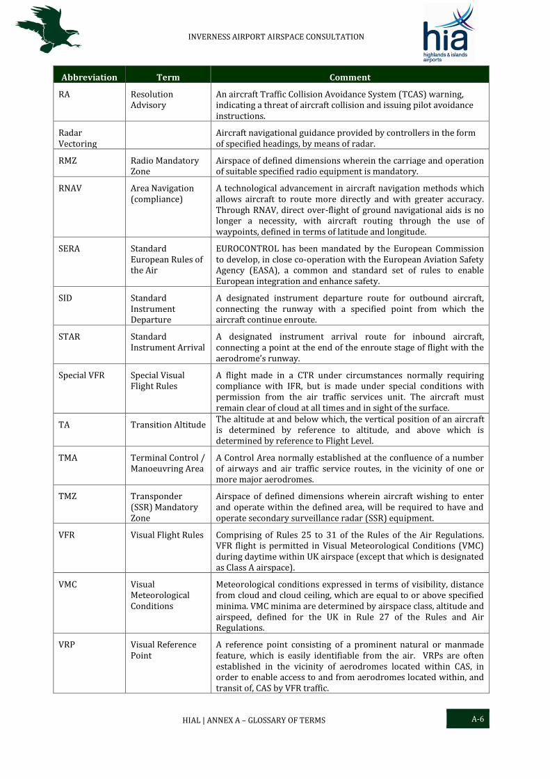
Abbreviation Term Comment
RA Resolution Advisory
An aircraft Traffic Collision Avoidance System (TCAS) warning, indicating a threat of aircraft collision and issuing pilot avoidance instructions.
Radar Vectoring
Aircraft navigational guidance provided by controllers in the form of specified headings, by means of radar.
RMZ Radio Mandatory Zone
Airspace of defined dimensions wherein the carriage and operation of suitable specified radio equipment is mandatory.
RNAV Area Navigation (compliance)
A technological advancement in aircraft navigation methods which allows aircraft to route more directly and with greater accuracy. Through RNAV, direct over-flight of ground navigational aids is no longer a necessity, with aircraft routing through the use of waypoints, defined in terms of latitude and longitude.
SERA Standard European Rules of the Air
EUROCONTROL has been mandated by the European Commission to develop, in close co-operation with the European Aviation Safety Agency (EASA), a common and standard set of rules to enable European integration and enhance safety.
SID Standard Instrument Departure
A designated instrument departure route for outbound aircraft, connecting the runway with a specified point from which the aircraft continue enroute.
STAR Standard Instrument Arrival
A designated instrument arrival route for inbound aircraft, connecting a point at the end of the enroute stage of flight with the aerodrome’s runway.
Special VFR Special Visual Flight Rules
A flight made in a CTR under circumstances normally requiring compliance with IFR, but is made under special conditions with permission from the air traffic services unit. The aircraft must remain clear of cloud at all times and in sight of the surface.
TA Transition Altitude The altitude at and below which, the vertical position of an aircraft is determined by reference to altitude, and above which is determined by reference to Flight Level.
TMA Terminal Control / Manoeuvring Area
A Control Area normally established at the confluence of a number of airways and air traffic service routes, in the vicinity of one or more major aerodromes.
TMZ Transponder (SSR) Mandatory Zone
Airspace of defined dimensions wherein aircraft wishing to enter and operate within the defined area, will be required to have and operate secondary surveillance radar (SSR) equipment.
VFR Visual Flight Rules Comprising of Rules 25 to 31 of the Rules of the Air Regulations. VFR flight is permitted in Visual Meteorological Conditions (VMC) during daytime within UK airspace (except that which is designated as Class A airspace).
VMC Visual Meteorological Conditions
Meteorological conditions expressed in terms of visibility, distance from cloud and cloud ceiling, which are equal to or above specified minima. VMC minima are determined by airspace class, altitude and airspeed, defined for the UK in Rule 27 of the Rules and Air Regulations.
VRP Visual Reference Point
A reference point consisting of a prominent natural or manmade feature, which is easily identifiable from the air. VRPs are often established in the vicinity of aerodromes located within CAS, in order to enable access to and from aerodromes located within, and transit of, CAS by VFR traffic.
INVERNESS AIRPORT AIRSPACE CONSULTATION
HIAL | ANNEX A – GLOSSARY OF TERMS A-7
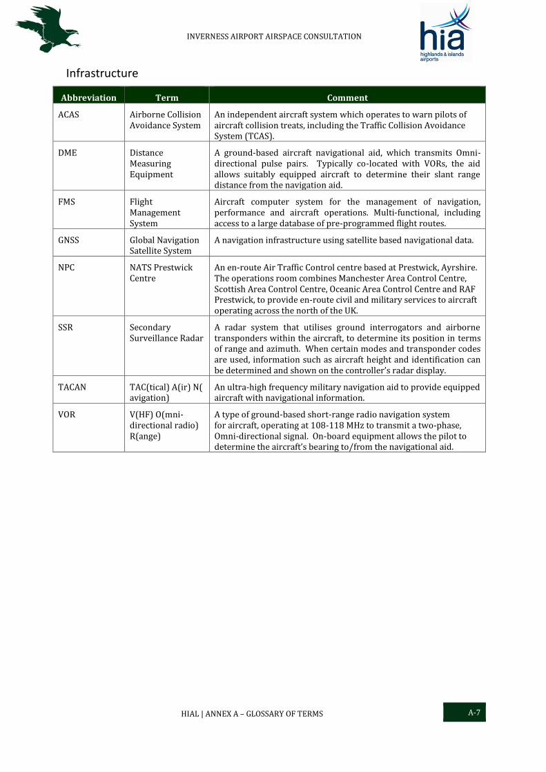
Infrastructure
Abbreviation Term Comment
ACAS Airborne Collision Avoidance System
An independent aircraft system which operates to warn pilots of aircraft collision treats, including the Traffic Collision Avoidance System (TCAS).
DME Distance Measuring Equipment
A ground-based aircraft navigational aid, which transmits Omni-directional pulse pairs. Typically co-located with VORs, the aid allows suitably equipped aircraft to determine their slant range distance from the navigation aid.
FMS Flight Management System
Aircraft computer system for the management of navigation, performance and aircraft operations. Multi-functional, including access to a large database of pre-programmed flight routes.
GNSS Global Navigation Satellite System
A navigation infrastructure using satellite based navigational data.
NPC NATS Prestwick Centre
An en-route Air Traffic Control centre based at Prestwick, Ayrshire. The operations room combines Manchester Area Control Centre, Scottish Area Control Centre, Oceanic Area Control Centre and RAF Prestwick, to provide en-route civil and military services to aircraft operating across the north of the UK.
SSR Secondary Surveillance Radar
A radar system that utilises ground interrogators and airborne transponders within the aircraft, to determine its position in terms of range and azimuth. When certain modes and transponder codes are used, information such as aircraft height and identification can be determined and shown on the controller’s radar display.
TACAN TAC(tical) A(ir) N(avigation)
An ultra-high frequency military navigation aid to provide equipped aircraft with navigational information.
VOR V(HF) O(mni-directional radio) R(ange)
A type of ground-based short-range radio navigation system for aircraft, operating at 108-118 MHz to transmit a two-phase, Omni-directional signal. On-board equipment allows the pilot to determine the aircraft’s bearing to/from the navigational aid.

INVERNESS AIRPORT AIRSPACE CONSULTATION
HIAL | ANNEX B – DRAFT IAP APPROACH PLATES B-1
Annex B – Draft IAP Approach Plates
B.1 GNSS Approach Inverness Runway 05
Figure C1: RNAV GNSS RWY 05
HIAL Digital Data.
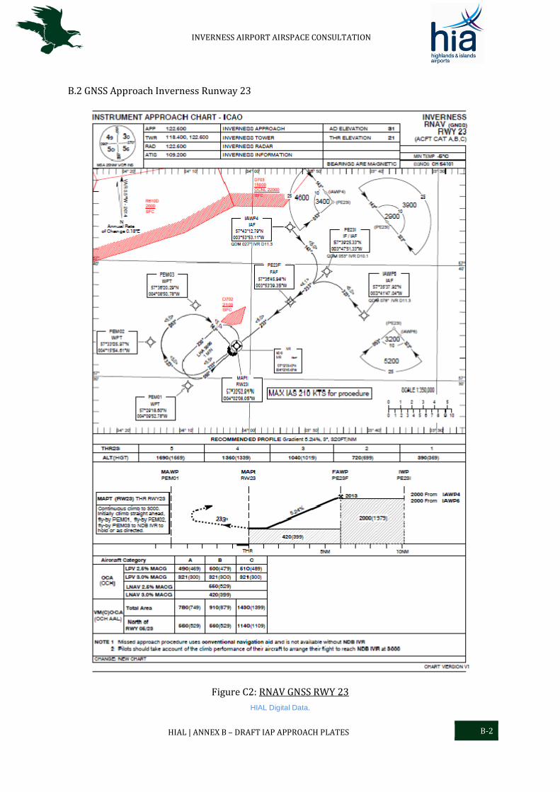
INVERNESS AIRPORT AIRSPACE CONSULTATION
HIAL | ANNEX B – DRAFT IAP APPROACH PLATES B-2
B.2 GNSS Approach Inverness Runway 23
Figure C2: RNAV GNSS RWY 23
HIAL Digital Data.

INVERNESS AIRPORT AIRSPACE CONSULTATION
HIAL | ANNEX C – PROPOSED CTR/A DATA C-1
Annex C – Proposed CTR/A Data
C.1 CTR/A Design (below 5,500 ft)
Figure D1: Proposed Inverness Class D and E+TMZ CAS
UK Civil Aviation Authority (CAA) / NATS Digital Data. VFR Chart Scotland, 500,000, June 2013
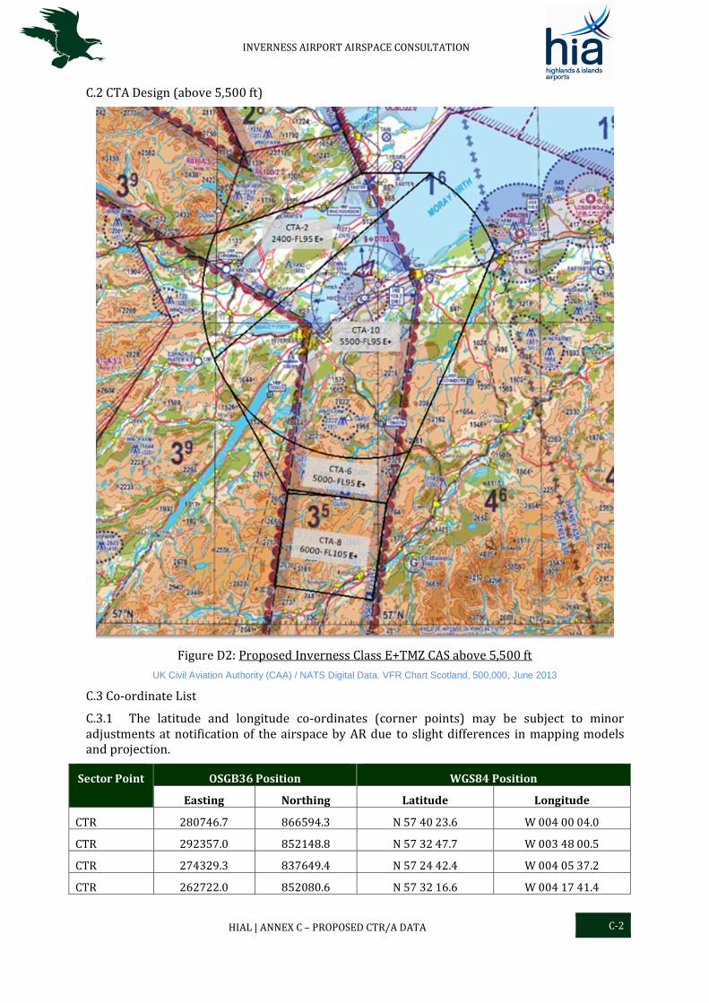
INVERNESS AIRPORT AIRSPACE CONSULTATION
HIAL | ANNEX C – PROPOSED CTR/A DATA C-2
C.2 CTA Design (above 5,500 ft)
Figure D2: Proposed Inverness Class E+TMZ CAS above 5,500 ft
UK Civil Aviation Authority (CAA) / NATS Digital Data. VFR Chart Scotland, 500,000, June 2013
C.3 Co-ordinate List
C.3.1 The latitude and longitude co-ordinates (corner points) may be subject to minor adjustments at notification of the airspace by AR due to slight differences in mapping models and projection.
Sector Point OSGB36 Position WGS84 Position
Easting Northing Latitude Longitude
CTR 280746.7 866594.3 N 57 40 23.6 W 004 00 04.0
CTR 292357.0 852148.8 N 57 32 47.7 W 003 48 00.5
CTR 274329.3 837649.4 N 57 24 42.4 W 004 05 37.2
CTR 262722.0 852080.6 N 57 32 16.6 W 004 17 41.4
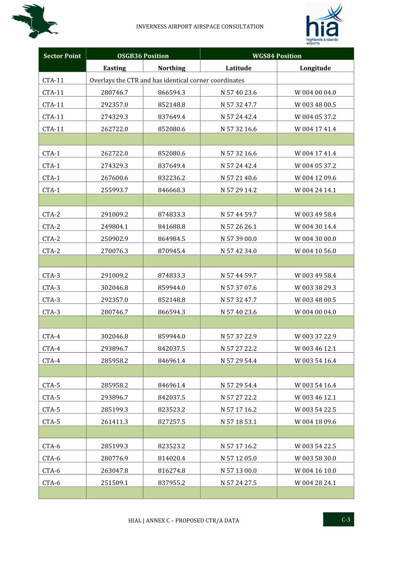
INVERNESS AIRPORT AIRSPACE CONSULTATION
HIAL | ANNEX C – PROPOSED CTR/A DATA C-3
Sector Point OSGB36 Position WGS84 Position
Easting Northing Latitude Longitude
CTA-11 Overlays the CTR and has identical corner coordinates
CTA-11 280746.7 866594.3 N 57 40 23.6 W 004 00 04.0
CTA-11 292357.0 852148.8 N 57 32 47.7 W 003 48 00.5
CTA-11 274329.3 837649.4 N 57 24 42.4 W 004 05 37.2
CTA-11 262722.0 852080.6 N 57 32 16.6 W 004 17 41.4
CTA-1 262722.0 852080.6 N 57 32 16.6 W 004 17 41.4
CTA-1 274329.3 837649.4 N 57 24 42.4 W 004 05 37.2
CTA-1 267600.6 832236.2 N 57 21 40.6 W 004 12 09.6
CTA-1 255993.7 846668.3 N 57 29 14.2 W 004 24 14.1
CTA-2 291009.2 874833.3 N 57 44 59.7 W 003 49 58.4
CTA-2 249804.1 841688.8 N 57 26 26.1 W 004 30 14.4
CTA-2 250902.9 864984.5 N 57 39 00.0 W 004 30 00.0
CTA-2 270076.3 870945.4 N 57 42 34.0 W 004 10 56.0
CTA-3 291009.2 874833.3 N 57 44 59.7 W 003 49 58.4
CTA-3 302046.8 859944.0 N 57 37 07.6 W 003 38 29.3
CTA-3 292357.0 852148.8 N 57 32 47.7 W 003 48 00.5
CTA-3 280746.7 866594.3 N 57 40 23.6 W 004 00 04.0
CTA-4 302046.8 859944.0 N 57 37 22.9 W 003 37 22.9
CTA-4 293896.7 842037.5 N 57 27 22.2 W 003 46 12.1
CTA-4 285958.2 846961.4 N 57 29 54.4 W 003 54 16.4
CTA-5 285958.2 846961.4 N 57 29 54.4 W 003 54 16.4
CTA-5 293896.7 842037.5 N 57 27 22.2 W 003 46 12.1
CTA-5 285199.3 823523.2 N 57 17 16.2 W 003 54 22.5
CTA-5 261411.3 827257.5 N 57 18 53.1 W 004 18 09.6
CTA-6 285199.3 823523.2 N 57 17 16.2 W 003 54 22.5
CTA-6 280776.9 814020.4 N 57 12 05.0 W 003 58 30.0
CTA-6 263047.8 816274.8 N 57 13 00.0 W 004 16 10.0
CTA-6 251509.1 837955.2 N 57 24 27.5 W 004 28 24.1
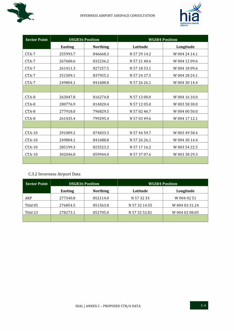
INVERNESS AIRPORT AIRSPACE CONSULTATION
HIAL | ANNEX C – PROPOSED CTR/A DATA C-4
Sector Point OSGB36 Position WGS84 Position
Easting Northing Latitude Longitude
CTA-7 255993.7 846668.3 N 57 29 14.2 W 004 24 14.1
CTA-7 267600.6 832236.2 N 57 21 40.6 W 004 12 09.6
CTA-7 261411.3 827257.5 N 57 18 53.1 W 004 18 09.6
CTA-7 251509.1 837955.2 N 57 24 27.5 W 004 28 24.1
CTA-7 249804.1 841688.8 N 57 26 26.1 W 004 30 14.4
CTA-8 263047.8 816274.8 N 57 13 00.0 W 004 16 10.0
CTA-8 280776.9 814020.4 N 57 12 05.0 W 003 58 30.0
CTA-8 277918.0 796829.5 N 57 02 46.7 W 004 00 50.0
CTA-8 261435.4 799295.4 N 57 03 49.6 W 004 17 12.1
CTA-10 291009.2 874833.3 N 57 44 59.7 W 003 49 58.4
CTA-10 249804.1 841688.8 N 57 26 26.1 W 004 30 14.4
CTA-10 285199.3 823523.2 N 57 17 16.2 W 003 54 22.5
CTA-10 302046.8 859944.0 N 57 37 07.6 W 003 38 29.3
C.3.2 Inverness Airport Data
Sector Point OSGB36 Position WGS84 Position
Easting Northing Latitude Longitude
ARP 277540.8 852114.0 N 57 32 33 W 004 02 51
Thld 05 276854.5 851563.8 N 57 32 14.55 W 004 03 31.24
Thld 23 278273.1 852705.0 N 57 32 52.81 W 004 02 08.05
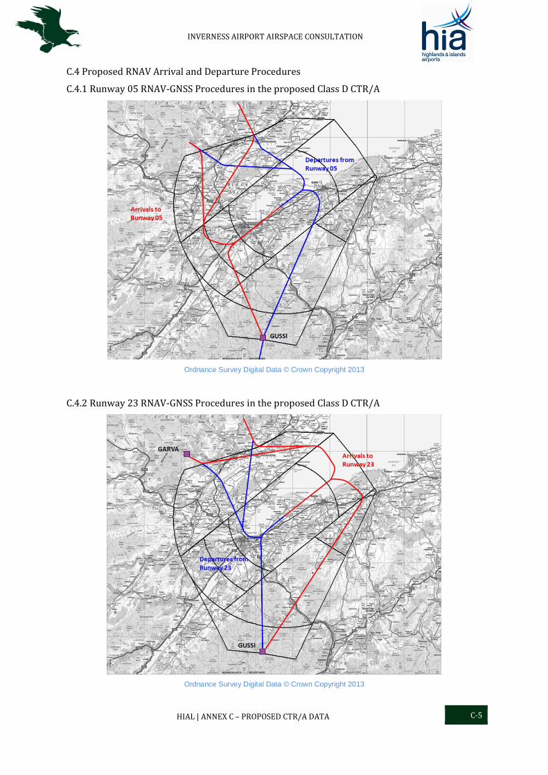
INVERNESS AIRPORT AIRSPACE CONSULTATION
HIAL | ANNEX C – PROPOSED CTR/A DATA C-5
C.4 Proposed RNAV Arrival and Departure Procedures
C.4.1 Runway 05 RNAV-GNSS Procedures in the proposed Class D CTR/A
Ordnance Survey Digital Data © Crown Copyright 2013
C.4.2 Runway 23 RNAV-GNSS Procedures in the proposed Class D CTR/A
Ordnance Survey Digital Data © Crown Copyright 2013

INVERNESS AIRPORT AIRSPACE CONSULTATION
HIAL | ANNEX C – PROPOSED CTR/A DATA C-6
C.5 Proposed Class D CTR and CTAs (common ceiling altitude 5,500 ft amsl)
C.5.1 CTR (Ceiling 2,000 ft) with overlaying CTA-11
C.5.2 CTA-1 Base altitude 1,500 ft
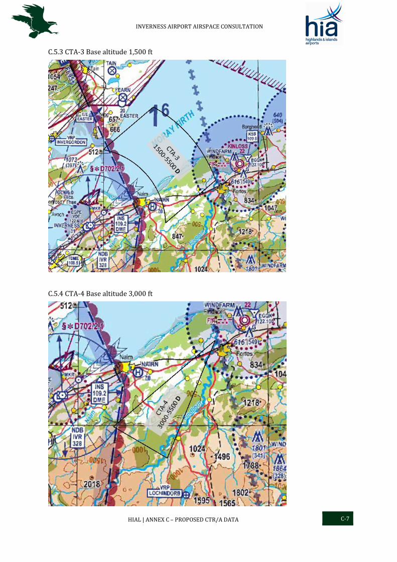
INVERNESS AIRPORT AIRSPACE CONSULTATION
HIAL | ANNEX C – PROPOSED CTR/A DATA C-7
C.5.3 CTA-3 Base altitude 1,500 ft
C.5.4 CTA-4 Base altitude 3,000 ft
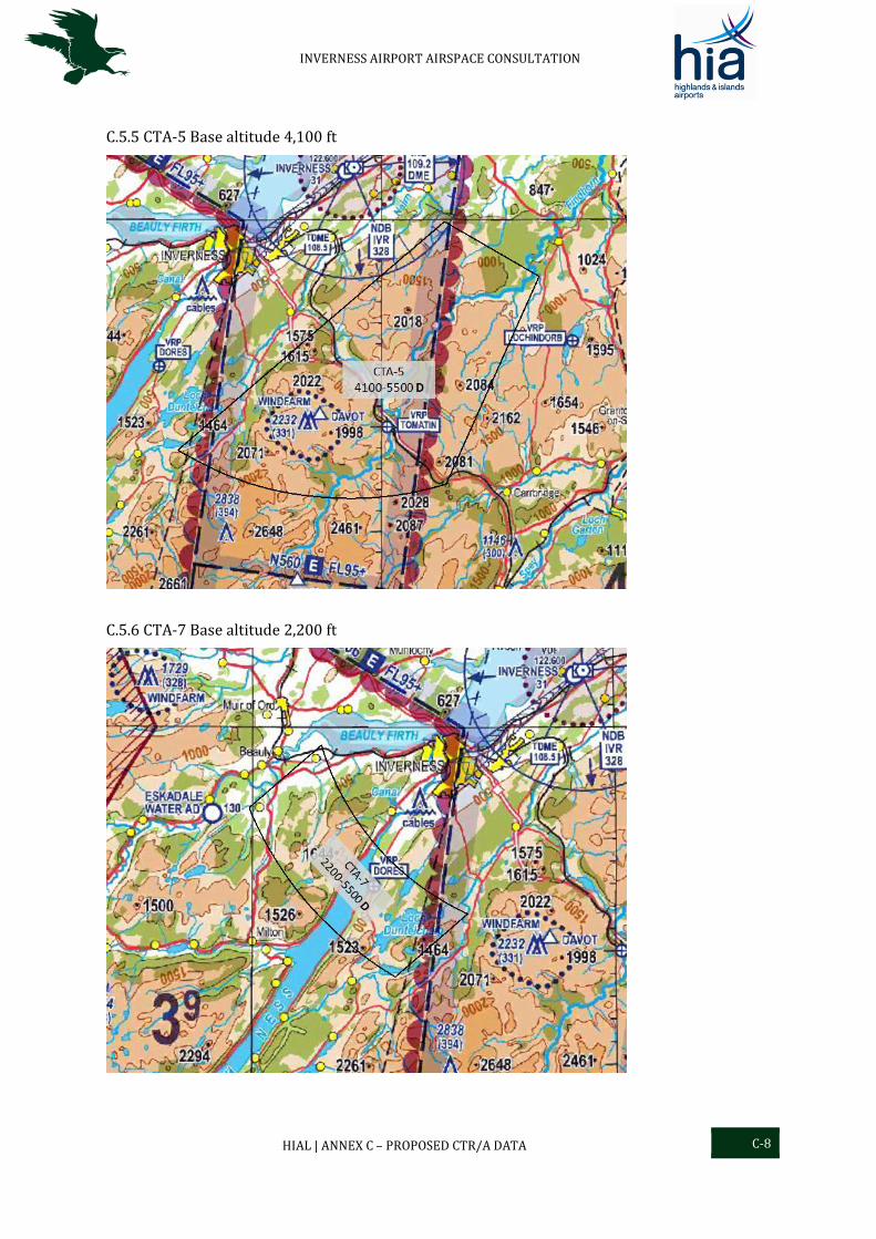
INVERNESS AIRPORT AIRSPACE CONSULTATION
HIAL | ANNEX C – PROPOSED CTR/A DATA C-8
C.5.5 CTA-5 Base altitude 4,100 ft
C.5.6 CTA-7 Base altitude 2,200 ft
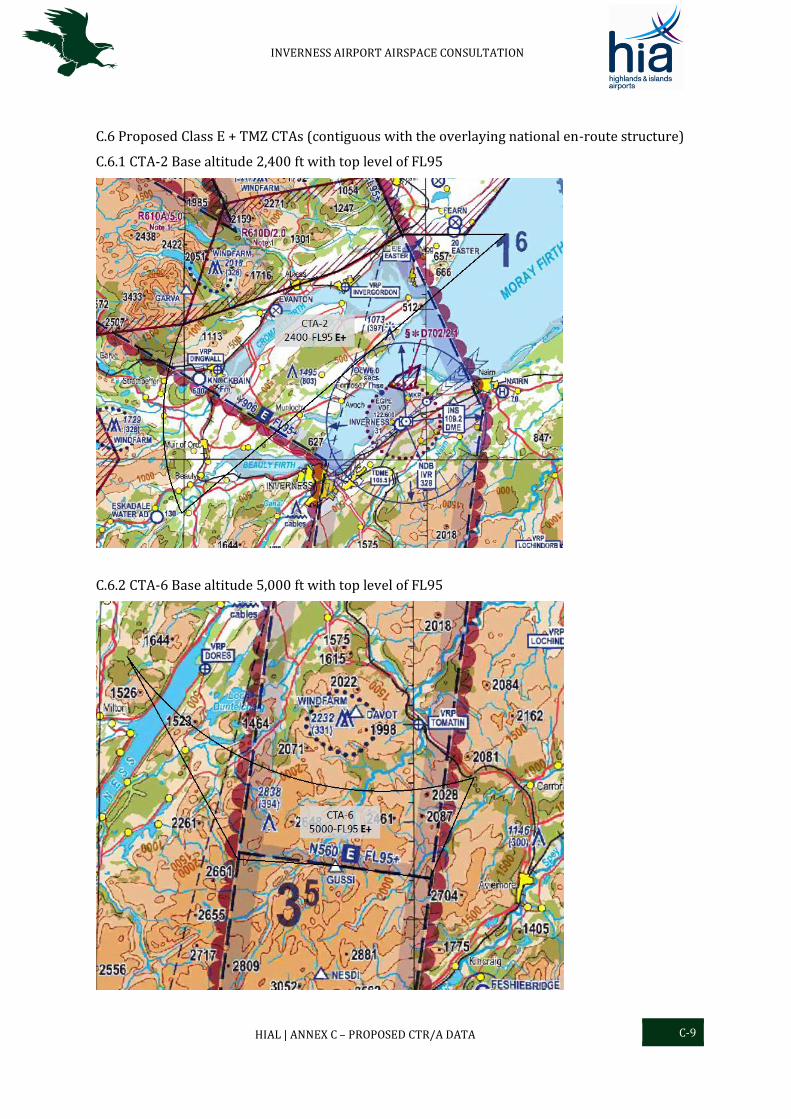
INVERNESS AIRPORT AIRSPACE CONSULTATION
HIAL | ANNEX C – PROPOSED CTR/A DATA C-9
C.6 Proposed Class E + TMZ CTAs (contiguous with the overlaying national en-route structure)
C.6.1 CTA-2 Base altitude 2,400 ft with top level of FL95
C.6.2 CTA-6 Base altitude 5,000 ft with top level of FL95
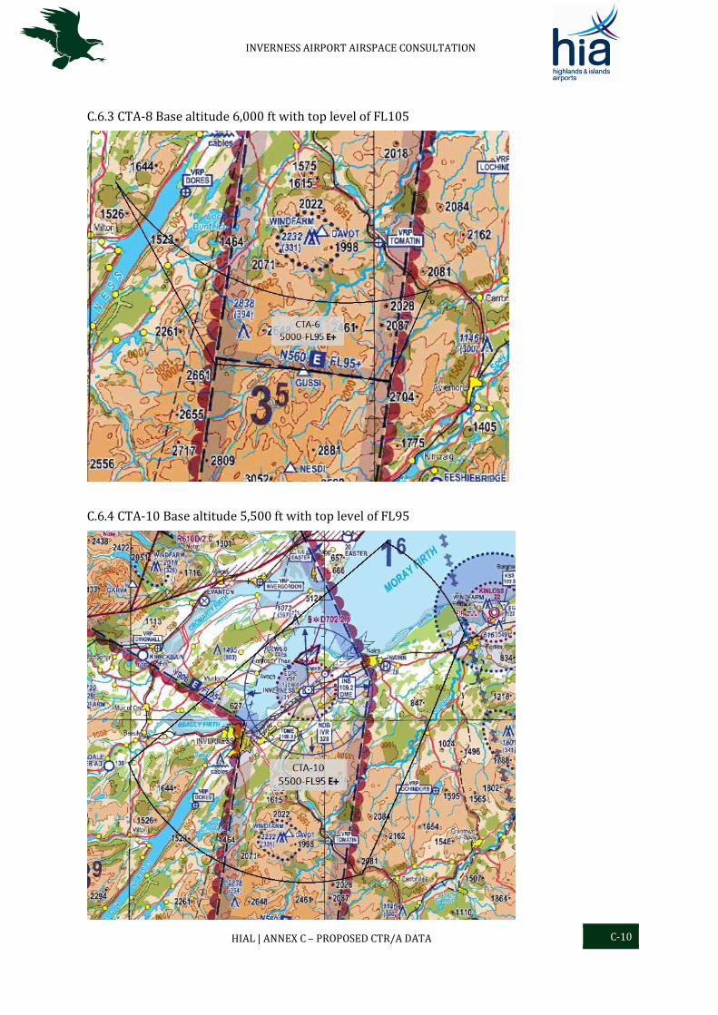
INVERNESS AIRPORT AIRSPACE CONSULTATION
HIAL | ANNEX C – PROPOSED CTR/A DATA C-10
C.6.3 CTA-8 Base altitude 6,000 ft with top level of FL105
C.6.4 CTA-10 Base altitude 5,500 ft with top level of FL95
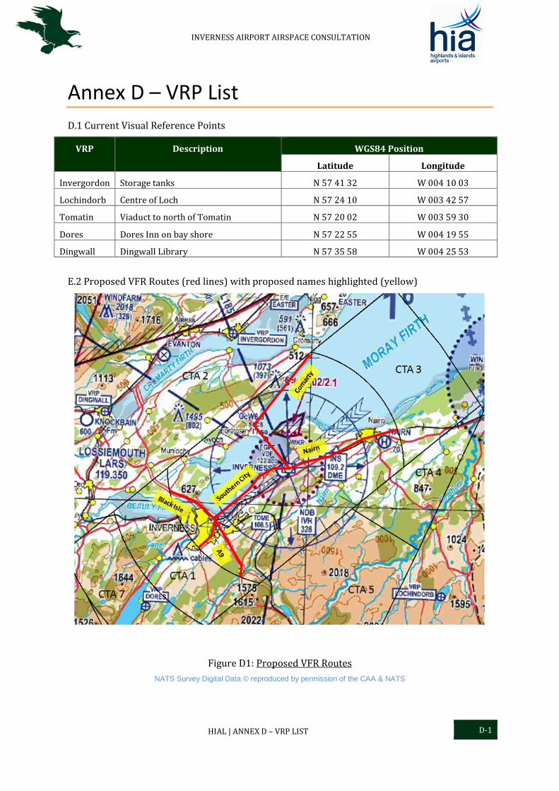
INVERNESS AIRPORT AIRSPACE CONSULTATION
HIAL | ANNEX D – VRP LIST D-1
Annex D – VRP List
D.1 Current Visual Reference Points
VRP Description WGS84 Position
Latitude Longitude
Invergordon Storage tanks N 57 41 32 W 004 10 03
Lochindorb Centre of Loch N 57 24 10 W 003 42 57
Tomatin Viaduct to north of Tomatin N 57 20 02 W 003 59 30
Dores Dores Inn on bay shore N 57 22 55 W 004 19 55
Dingwall Dingwall Library N 57 35 58 W 004 25 53
E.2 Proposed VFR Routes (red lines) with proposed names highlighted (yellow)
Figure D1: Proposed VFR Routes
NATS Survey Digital Data © reproduced by permission of the CAA & NATS