hhw-80 ecoheat operation, service & parts manual · 2018-07-19 · the limit based on the set...
TRANSCRIPT
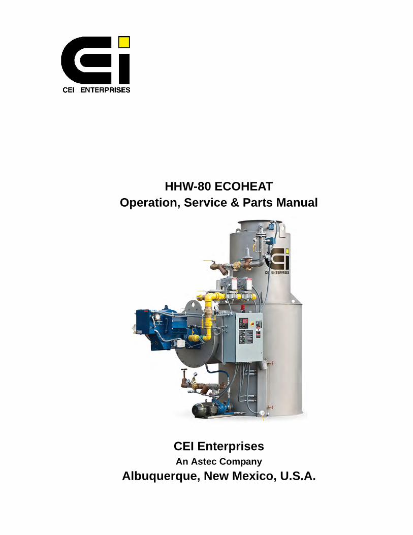
HHW-80 ECOHEATOperation, Service & Parts Manual
CEI EnterprisesAn Astec Company
Albuquerque, New Mexico, U.S.A.

ii
iii
C18-054, CEI HHW-80 ECOHEAT
C18-054, CEI HHW-80 ECOHEAT
IMPROPER INSTALLATION, ADJUSTMENT, ALTERATION, SERVICE OR MAINTENANCE TO THE BURNER CAN CAUSE INJURY OR PROPERTY DAMAGE.
Because of the critical nature of burner operations, CEI recommends that you retain the services of a CEI factory trained and licensed burner technician and/or a local licensed burner/boiler technician to check and, if required, adjust the burner prior to commissioning your equipment.
WARNING!

iv
C18-054, CEI HHW-80 ECOHEAT
v
Contents
Section 1: Operations ...................................................... 1Overview ................................................................................... 3Safety ........................................................................................ 3
IF YOU SMELL GAS .....................................................................3WARNING! ....................................................................................3Safety Symbols .............................................................................4
HHW-80 Components ............................................................... 5Burner ............................................................................................6Tank ..............................................................................................6Control Panel .................................................................................7
Installation ............................................................................... 10Inspection ....................................................................................10Position ........................................................................................11Connect Electrical .......................................................................11Connect Compressed Air ............................................................12Connect Natural Gas ...................................................................13Connect Water ............................................................................13Startup .........................................................................................14
UT150 Burner Modulation Controller ....................................... 17
Section 2: Maintenance & Troubleshooting .................. 21Calcium Clean-Out ......................................................................23Cleaning Strainers .......................................................................25Freeze Protection ........................................................................25Checking Water Level Switches ..................................................26Checking the Flame Scanner ......................................................26Checking the Pilot Gas Pressure Regulator ................................27Checking the High Fuel Gas Pressure Switch ............................27Checking the Low Fuel Gas Pressure Switch .............................28Checking the High Flue Gas Stack Temperature Switch ............28Checking the Auxiliary Contacts For Water Pump Motor ............30Checking Auxiliary Contacts For the Combustion Air Blower Motor ...........................................................................................31Checking the Low Combustion Air Switch ...................................31
Maintenance Schedule ............................................................ 32Troubleshooting ....................................................................... 33Modulation Motor Troubleshooting .......................................... 34
What the Modulation Motor Does ................................................35
vi
Key Components of Concern ......................................................35Interaction with Fireye Burner Controls .......................................35Interaction with Modulation Controller .........................................36Common Problem .......................................................................36Other Problems ...........................................................................37Symptoms of Problems ...............................................................37Remedy for Faulty Electrical Connections ..................................37Checking and Resetting Cams ....................................................37Checking Transformer in the Modulation Motor ..........................38Checking Terminal Board and Motor ...........................................38
HHW Burner – Left Side ..........................................................41HHW Burner – Right Side ........................................................42Burner – Internal ......................................................................43HHW Water Heater Parts & Assemblies ..................................45Water Train & Gas Train Components ....................................46Water Pump & Water Level Indicator Components .................47Electrical ..................................................................................48
....................................................................................................49
Specifications .................................................................51Contact Information .................................................................55
CEI Service (General Contact) ....................................................55Departmental Contacts ................................................................55
C18-054, CEI HHW-80 ECOHEAT
Section 1: Operations

2
C18-054, CEI HHW-80 ECOHEAT Overview
3
Overview
The HHW-80 ECOHEAT is an on-demand heater meaning the burner is fired toheat only the water used, as it is used. Your HHW-80 ECOHEAT heater provide aconstant supply of hot water flowing at a rate of up to 1200 gpm while raising thewater temperature up to 185°F. A high thermal efficiency (up to 99%) helps keepthe exhaust stack temperature near the temperature of the incoming water.
The HHW-80 ECOHEAT serial and model number is located on the electrical cab-inet door.
Note: Please supply the serial number when requesting service support or making reference to the tank for spare parts or operational questions.
Safety
Safety is of prime concern whenever using an electrically operated, hightemperature device. Please use proper safety precautions and follow all com-pany, local, state and federal regulations for operating potentially dangerousequipment. Lock-out/tag-out equipment before performing maintenance.
IF YOU SMELL GAS
1. Open windows.
2. Do not touch electrical switches.
3. Extinguish any open flame.
4. Call your gas supplier immediately.
Do not store or use gasoline or other flammable liquids and vapors in thevicinity of this or any other appliance.
WARNING!
Although your HHW-80 ECOHEAT heater provides safe, unattended operation,improper installation, adjustment, alteration, service or maintenance can causeinjury or property damage. For assistance or additional information contact CEI.
This manual gives basic instructions which must be observed during installation,operation and maintenance of your HHW-80 ECOHEAT. It is imperative that thismanual be read by the responsible personnel/operator(s) prior to the commission-ing of any liquid media storage system. It must always be kept available at the site ofinstallation. It is not only the general safety instructions contained in this Safetysection which must be observed, but also the specific information provided in thefollowing sections and other applicable manuals.
Safety
4
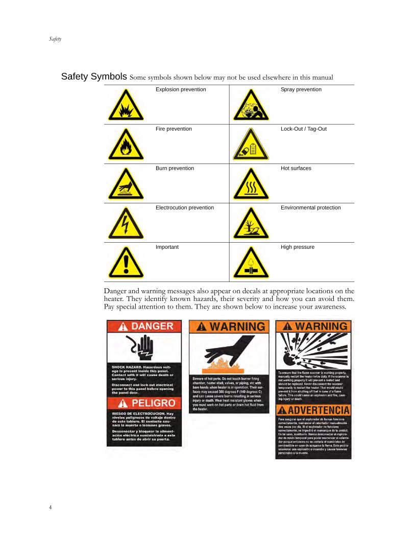
Safety Symbols Some symbols shown below may not be used elsewhere in this manual
Danger and warning messages also appear on decals at appropriate locations on theheater. They identify known hazards, their severity and how you can avoid them.Pay special attention to them. They are shown below to increase your awareness.
Explosion prevention Spray prevention
Fire prevention Lock-Out / Tag-Out
Burn prevention Hot surfaces
Electrocution prevention Environmental protection
Important High pressure
C18-054, CEI HHW-80 ECOHEAT HHW-80 Components
5
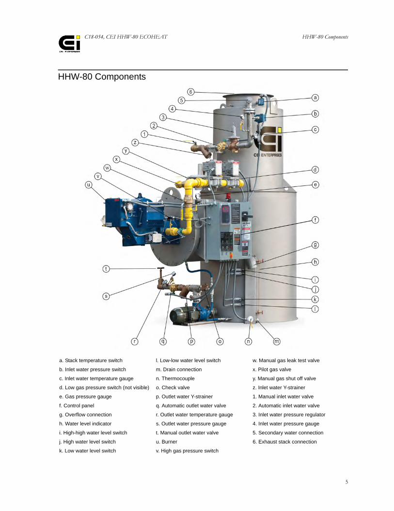
HHW-80 Components
a. Stack temperature switch l. Low-low water level switch w. Manual gas leak test valve
b. Inlet water pressure switch m. Drain connection x. Pilot gas valve
c. Inlet water temperature gauge n. Thermocouple y. Manual gas shut off valve
d. Low gas pressure switch (not visible) o. Check valve z. Inlet water Y-strainer
e. Gas pressure gauge p. Outlet water Y-strainer 1. Manual inlet water valve
f. Control panel q. Automatic outlet water valve 2. Automatic inlet water valve
g. Overflow connection r. Outlet water temperature gauge 3. Inlet water pressure regulator
h. Water level indicator s. Outlet water pressure gauge 4. Inlet water pressure gauge
i. High-high water level switch t. Manual outlet water valve 5. Secondary water connection
j. High water level switch u. Burner 6. Exhaust stack connection
k. Low water level switch v. High gas pressure switch
HHW-80 Components
6
Burner
A fully modulated unit running on natural gas (or propane), the burner fires onlywhen heated water is requested. Because it is modulated, the burner only runs at arate high enough to heat the requested quantity of water thus saving fuel.
Tank
Cold water is introduced into the tank top as a spray where it migrates downthrough a bed of stainless steel packing rings. Packing temporarily slows the flow ofwater and provides surface area for heat transfer. Hot gasses rising from the burnerheat the packing and, through contact with the heated packing, heats the water.Low-level switches prevent the burner from firing when there is no flow of waterthrough the heater to ensure the structural walls of the heater are not damaged byoverheating. High-level switches shut off the burner and incoming water. Addition-ally, there is a water overflow and a drain valve.
C18-054, CEI HHW-80 ECOHEAT HHW-80 Components
7
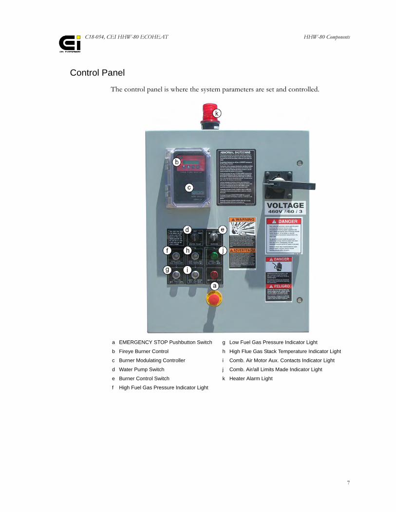
Control Panel
The control panel is where the system parameters are set and controlled.
a EMERGENCY STOP Pushbutton Switch g Low Fuel Gas Pressure Indicator Light
b Fireye Burner Control h High Flue Gas Stack Temperature Indicator Light
c Burner Modulating Controller i Comb. Air Motor Aux. Contacts Indicator Light
d Water Pump Switch j Comb. Air/all Limits Made Indicator Light
e Burner Control Switch k Heater Alarm Light
f High Fuel Gas Pressure Indicator Light
HHW-80 Components
8
Emergency Stop Pushbutton Switch
Push in this switch to immediately shut down the heater. Use it only in an emer-gency. The switch incorporates a light that comes on when the switch is pushed in.Unlike using the BURNER switch to shut down, the emergency stop switchremoves electrical power from all other controls and immediately shuts down theheater without a post purge.
Burner Modulating Controller
The modulating controller, a Yokogawa UT150, provides two functions:• Burner modulation control• Burner on/off control
Burner modulation control. This function of the controller controls heating ofthe water to maintain a temperature setting that has been preset by the operator. Itsenses water temperature from a thermocouple. It processes the output voltage ofthe thermocouple and sends control signals to the Honeywell modulating actuatorwhich either increases or decreases the firing rate as required to maintain watertemperature at set point.
Burner on-off control. This function of the modulating controller shuts off theburner completely. This happens if system heat demand decreases, allowing watertemperature to reach a limit equal to the set point plus a predetermined value. Thisvalue is normally set manually at 10. It is known as a floating value since it createsthe limit based on the set point. Thus, if its value is 10 and the set point is 140degrees F, the limit is 150 degrees F (the sum of 140 plus 10). After the water coolsdown about 20 degrees the controller initiates a new burner cycle.
Fireye Burner Controls
The Fireye burner controls consist of a Fireye YB110 Burner Management Controland YP100 Programmer Module (inside the panel), and the BV512 Display (indi-cated). It is a microprocessor based burner management control system. The sys-tem provides the proper burner sequencing, ignition and burner monitoringprotection. In conjunction with limit and operating controls it sequences theburner/blower motor, ignition transformer and fuel valves to provide for properand safe burner operation.
The system will close all fuel valves within four seconds (maximum) following aflame failure or at the end of the pilot trial for ignition period if no flame isdetected. An alarm circuit will be energized following a safety lockout.
The system must be reset using a manual reset button on the display after an abnor-mal condition has been cleared.
C18-054, CEI HHW-80 ECOHEAT HHW-80 Components
9
Water Pump Switch
This is a manually controlled switch for turning the water pump on and off. Theswitch is in series with the breaker auxiliary contacts of the motor controller andmust be closed for power to reach the motor. When the switch is set to ON, thewater pump will run as long as there is an adequate amount of water in the heaterreservoir. The controls are designed to allow a signal from a remote tank to start/stop the heater. The switch must be set to AUTO for this feature to work.
Burner Control Switch
This is a manually controlled switch for turning the burner on and off. It must beset to ON or AUTO for the heater to operate. The controls are designed to allow asignal from a remote tank to start/stop the heater. The switch must be set toAUTO for this feature to work. When this switch is set to ON the burner will comeon and off as needed, independently of external control signals. The burner switchmust be set to ON or AUTO for any of the five indicator lights to work.
High Fuel Gas Pressure Indicator Light
This indicator light denotes the status of the high fuel gas pressure switch. Whenthe light is on the fuel gas pressure is normal and the switch is closed. When thelight is off it indicates that the fuel gas pressure exceeded the setpoint. This switchis part of the limit circuit and will shut down the burner when open. The switch hasa manual reset button.
Note: Not all heaters have a high fuel gas pressure switch. But the panel may still have an indicator light for the switch. In that case the switch is replaced by a jumper wire. Thus, the light will react the same as it would with a switch in its normal pressure state.
Low Fuel Gas Pressure Indicator Light
This indicator light denotes the status of the low fuel gas pressure switch. When thelight is on the fuel gas pressure is normal and the switch is closed. When the light isoff it indicates that the fuel gas pressure dropped lower than the setpoint. Thisswitch is part of the limit circuit and will shut down the burner when open. Theswitch has a manual reset button.
Note: Not all heaters have a low fuel gas pressure switch. But the panel may still have an indicator light for the switch. In that case the switch is replaced by a jumper wire. Thus, the light will react the same as it would with a switch in its normal pressure state.
High Flue Gas Stack Temperature Indicator Light
This indicator light denotes temperature status of gas in the exhaust stack. It is elec-trically connected to the high flue gas stack temperature switch mounted in theexhaust stack.
Installation
10
When the light is on, temperature of the gas is within normal operating range andthe switch contacts are closed. When the light is off, gas temperature has exceededits factory setting of 130 degrees F and the contacts are open.
The switch is also part of the limit circuit and will shut down the heater when theswitch is opened. The switch must be manually reset.
Combination Air Motor Auxillary Contacts Indicator Light
This indicator light denotes the status of auxiliary contacts on the motor controllerthat connects electrical power to the burner blower motor. When the indicator lightis on electrical power is connected to the blower motor. When the light is off thecontacts are open because electrical power is not connected to the motor.
The contacts are also part of the limit circuit and will shut down the heater whenopened. The contacts automatically close when power is restored to the motor.
Combination Air/all Limits Made Indicator Light
This light functions as a low combustion air pressure light in addition to a limitsmade light. When the light is on it indicates that the combustion air pressure is nor-mal and that the combustion air switch in the burner housing is closed. When thelight is on it also indicates that all other limit switches are closed. When the light isout the combustion air pressure is too low and the combustion air switch is open.
Heater Alarm Light
This light denotes the status of the heater alarm system. When the light is flashingthe heater is in an alarm state. The alarm is controlled by the Fireye burner controlwhich turns on the alarm when it detects a variety of abnormal conditions. The Fir-eye display shows one of several messages to report the condition that caused thealarm.
Installation
Inspection
CEI takes great care in the construction and shipping of each HHW-80 ECO-HEAT so that it will arrive ready for installation and operation. However some-times the unforeseen happens and damage occurs during loading, shipment and/ordelivery.
We recommend a full inspection of the unit for any signs of damage and/or miss-ing parts before installing the unit. In the unlikely event that damage has occurredor a part (or parts) is missing, please contact your CEI representative before con-tinuing with installation.
C18-054, CEI HHW-80 ECOHEAT Installation
11
Position
The HHW-80 ECOHEAT is normally positioned so its heated water can easily beconnected to the intended destination equipment and where the burner exhaustgases can safely dissipate.
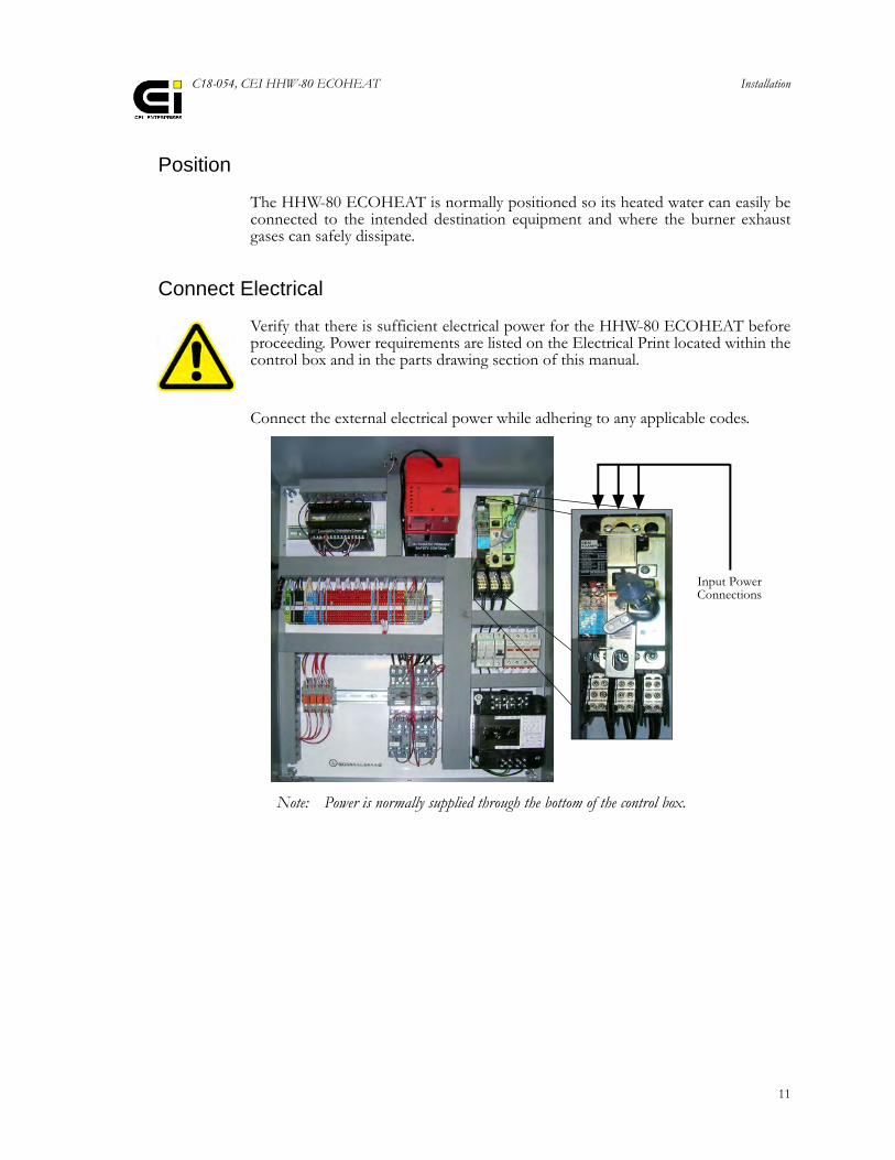
Connect Electrical
Verify that there is sufficient electrical power for the HHW-80 ECOHEAT beforeproceeding. Power requirements are listed on the Electrical Print located within thecontrol box and in the parts drawing section of this manual.
Connect the external electrical power while adhering to any applicable codes.
Note: Power is normally supplied through the bottom of the control box.
Input Power Connections
Installation
12
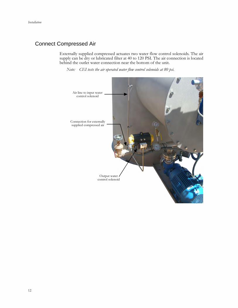
Connect Compressed Air
Externally supplied compressed actuates two water flow control solenoids. The airsupply can be dry or lubricated filter at 40 to 120 PSI. The air connection is locatedbehind the outlet water connection near the bottom of the unit.
Note: CEI tests the air operated water flow control solenoids at 80 psi.
Air line to input water control solenoid
Output water control solenoid
Connection for externally supplied compressed air

C18-054, CEI HHW-80 ECOHEAT Installation
13
Connect Natural Gas
1. Verify that there is a sufficient supply of Natural Gas for the HHW-80ECOHEAT before proceeding (see the Specifications section at the end ofthis manual).
2. Make sure the heater’s gas inlet supply valve is closed then connect the Gassupply to the inlet on the Heater. Open the source gas supply valve and checkfor leaks. Correct as necessary.
Connect Water
Verify that there is a sufficient supply of water for the HHW-80 ECOHEAT beforeproceeding (see the Specifications section at the end of this manual).
There are two primary water connections, incoming cold and outgoing heatedwater. The incoming cold water connection is near the top of the unit while theoutgoing heater water connection is near the bottom adjacent to the pump/motorassembly. A third connection is for a permanent drain. Connect the plumbing,check for leaks and correct as necessary.
Gas Inlet Valve(shown closed)
Gas Supply Inlet
Installation
14
Startup
Prior to startup
The following conditions are required prior to startup:• The incoming gas supply line pressure is 0.5 psig.• The heater is properly installed, piped, and wired.• Water piping should be complete and leak-tested.• Air connected to outlet water valve.
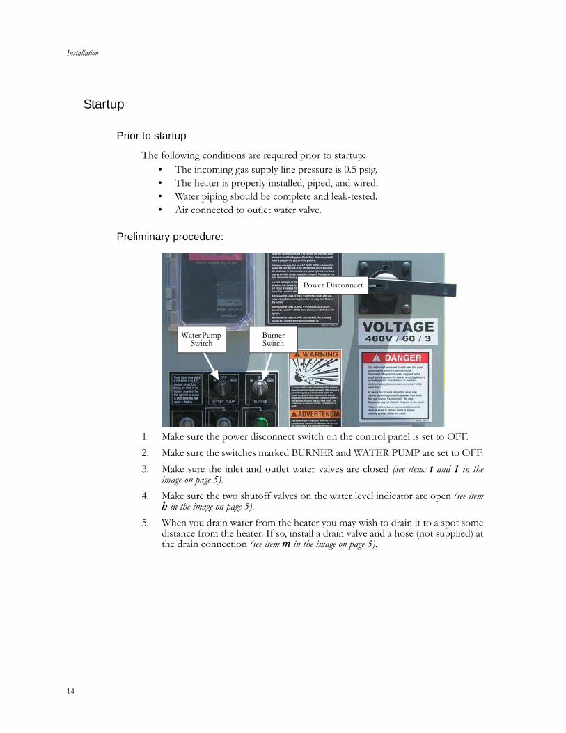
Preliminary procedure:
1. Make sure the power disconnect switch on the control panel is set to OFF.
2. Make sure the switches marked BURNER and WATER PUMP are set to OFF.
3. Make sure the inlet and outlet water valves are closed (see items t and 1 in theimage on page 5).
4. Make sure the two shutoff valves on the water level indicator are open (see itemh in the image on page 5).
5. When you drain water from the heater you may wish to drain it to a spot somedistance from the heater. If so, install a drain valve and a hose (not supplied) atthe drain connection (see item m in the image on page 5).
Power Disconnect
Water Pump Switch
Burner Switch
C18-054, CEI HHW-80 ECOHEAT Installation
15
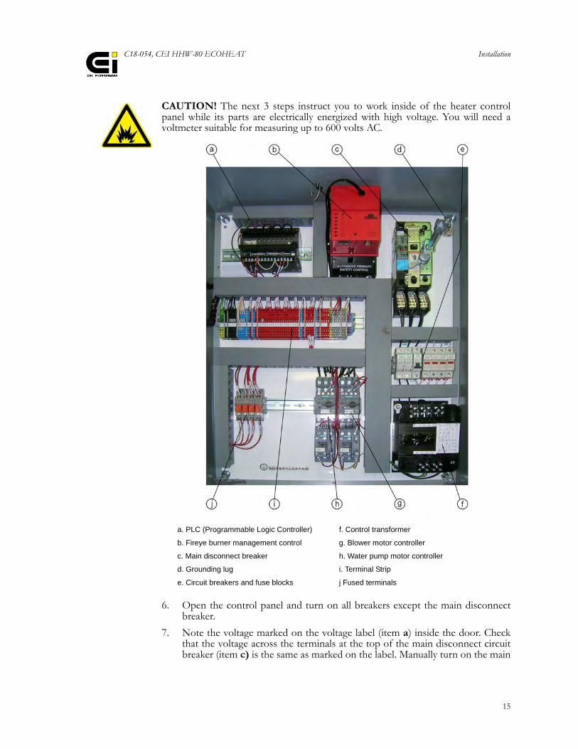
CAUTION! The next 3 steps instruct you to work inside of the heater controlpanel while its parts are electrically energized with high voltage. You will need avoltmeter suitable for measuring up to 600 volts AC.
6. Open the control panel and turn on all breakers except the main disconnectbreaker.
7. Note the voltage marked on the voltage label (item a) inside the door. Checkthat the voltage across the terminals at the top of the main disconnect circuitbreaker (item c) is the same as marked on the label. Manually turn on the main
a. PLC (Programmable Logic Controller) f. Control transformer
b. Fireye burner management control g. Blower motor controller
c. Main disconnect breaker h. Water pump motor controller
d. Grounding lug i. Terminal Strip
e. Circuit breakers and fuse blocks j Fused terminals
Installation
16
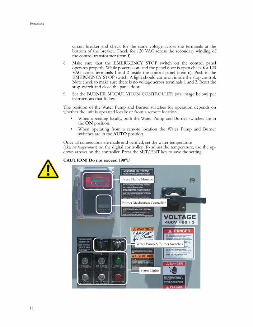
circuit breaker and check for the same voltage across the terminals at thebottom of the breaker. Check for 120 VAC across the secondary winding ofthe control transformer (item f).
8. Make sure that the EMERGENCY STOP switch on the control paneloperates properly. While power is on, and the panel door is open check for 120VAC across terminals 1 and 2 inside the control panel (item c). Push in theEMERGENCY STOP switch. A light should come on inside the stop control.Now check to make sure there is no voltage across terminals 1 and 2. Reset thestop switch and close the panel door.
9. Set the BURNER MODULATION CONTROLLER (see image below) perinstructions that follow.
The position of the Water Pump and Burner switches for operation depends onwhether the unit is operated locally or from a remote location.
• When operating locally, both the Water Pump and Burner switches are inthe ON position.
• When operating from a remote location the Water Pump and Burnerswitches are in the AUTO position.
Once all connections are made and verified, set the water temperature (aka set temperature) on the digital controller. To adjust the temperature, use the up-down arrows on the controller. Press the SET/ENT key to save the setting.
CAUTION! Do not exceed 190°F
Burner Modulation Controller
Water Pump & Burner Switches
Status Lights
Fireye Flame Monitor
C18-054, CEI HHW-80 ECOHEAT UT150 Burner Modulation Controller
17
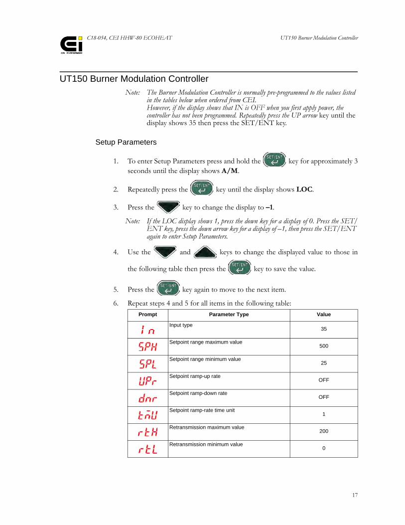
UT150 Burner Modulation ControllerNote: The Burner Modulation Controller is normally pre-programmed to the values listed
in the tables below when ordered from CEI.However, if the display shows that IN is OFF when you first apply power, the controller has not been programmed. Repeatedly press the UP arrow key until the display shows 35 then press the SET/ENT key.
Setup Parameters
1. To enter Setup Parameters press and hold the key for approximately 3seconds until the display shows A/M.
2. Repeatedly press the key until the display shows LOC.
3. Press the key to change the display to –1.
Note: If the LOC display shows 1, press the down key for a display of 0. Press the SET/ENT key, press the down arrow key for a display of –1, then press the SET/ENT again to enter Setup Parameters.
4. Use the and keys to change the displayed value to those in
the following table then press the key to save the value.
5. Press the key again to move to the next item.
6. Repeat steps 4 and 5 for all items in the following table:
Prompt Parameter Type Value
Input type35
Setpoint range maximum value500
Setpoint range minimum value25
Setpoint ramp-up rateOFF
Setpoint ramp-down rateOFF
Setpoint ramp-rate time unit1
Retransmission maximum value200
Retransmission minimum value0
UT150 Burner Modulation Controller
18
7. When finished entering the Setup Parameters:
Operating Parameters
Note: The controller automatically returns to the Operator mode after 2 minutes if no buttons are pressed.
1. To enter Operating Parameters press and hold the key for approxi-mately 3 seconds until the display shows SP.
2. Use the and to change the displayed value to those in the
following table then press the key to save the value.
3. Press the key again to move to the next item.
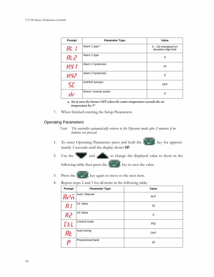
4. Repeat steps 2 and 3 for all items in the following table:
Alarm 1 type a 5 – De-energized on deviation high limit
Alarm 2 type0
Alarm 1 hysteresis15
Alarm 2 hysteresis0
SUPER functionOFF
Direct / reverse action0
a. Set to turn the burner OFF when the water temperature exceeds the set temperature by 5°
Prompt Parameter Type Value
Prompt Parameter Type Value
Auto / ManualAUT
A1 Value10
A2 Value0
Control modePID
Auto-tuningOFF
Proportional band24
C18-054, CEI HHW-80 ECOHEAT UT150 Burner Modulation Controller
19
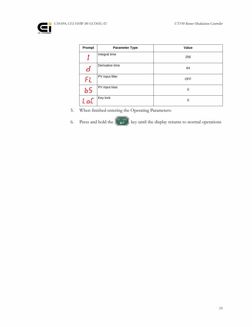
5. When finished entering the Operating Parameters:
6. Press and hold the key until the display returns to normal operations
Integral time256
Derivative time64
PV input filterOFF
PV input bias0
Key lock0
Prompt Parameter Type Value

UT150 Burner Modulation Controller
20
C18-054, CEI HHW-80 ECOHEAT
Section 2: Maintenance & Troubleshooting

22
C18-054, CEI HHW-80 ECOHEAT
23
Calcium Clean-Out
Build up of calcium inside the heater can be a matter of serious concern. Excessivebuildup can lead to heater malfunctions and heater damage. The rate of calciumbuildup varies widely depending on the amount of calcium in the water supply andoperating conditions.
Frequency of checks and down-time
The heater should be checked at least once a month while in regular use to makesure calcium buildup has not reached a point that affects operation of the heater. Ifno adverse signs are found, the checks can be made less frequently. However, if theheater is moved to a new location or if the water supply is changed, revert back tomonthly checks.
When excessive calcium buildup is found you need to plan down-time for clean-out. You may need to allow a full day for clean-out. Do not delay any longer thanabsolutely necessary.
Symptoms of excessive build-up
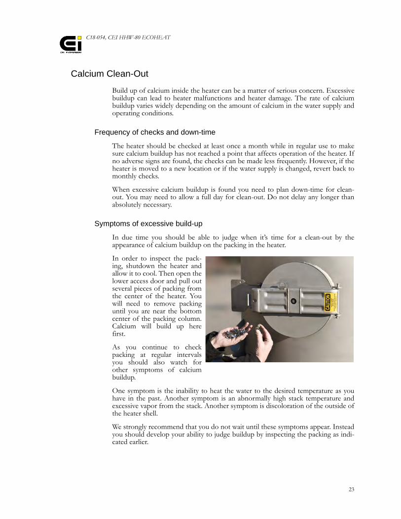
In due time you should be able to judge when it’s time for a clean-out by theappearance of calcium buildup on the packing in the heater.
In order to inspect the pack-ing, shutdown the heater andallow it to cool. Then open thelower access door and pull outseveral pieces of packing fromthe center of the heater. Youwill need to remove packinguntil you are near the bottomcenter of the packing column.Calcium will build up herefirst.
As you continue to checkpacking at regular intervalsyou should also watch forother symptoms of calciumbuildup.
One symptom is the inability to heat the water to the desired temperature as youhave in the past. Another symptom is an abnormally high stack temperature andexcessive vapor from the stack. Another symptom is discoloration of the outside ofthe heater shell.
We strongly recommend that you do not wait until these symptoms appear. Insteadyou should develop your ability to judge buildup by inspecting the packing as indi-cated earlier.
24
Cleaning methods
There are two methods for cleaning calcium from your heater. The first methodrequires shutting it down and removing all the packing. The packing must besoaked in a chemical intended for dissolving calcium. Once the calcium has beenremoved from the packing, rinse it and put it back in the heater.
The second method is to clean the inside of the heater and packing simultaneously.This is done by introducing a chemical cleaner into the top of the heater. Do thiswhile circulating water from the reservoir through the heater with the burner off.This may take several hours, depending on the amount of calcium buildup.
To circulate its water, first fill the reservoir. Then temporarily install a pipe or hosefrom the water outlet valve to the secondary water connection. Then operate thewater pump to circulate the water containing the cleaning chemical.
The cleaning chemical will probably work better soon after the heater has been shutdown, while it is still warm.
The chamber that contains the floats for water level switches should be cleanedseparately.
Chemicals
A variety of chemicals are available for removing calcium deposits. Some containsulfamic acid. Others contain citric acid. You may wish to use stronger chemicalson the packing while it is out of the heater and milder chemicals inside the heater.Keep in mind that chemicals circulating through the heater will contact non-stain-less steel parts, such as circulating pump, bronze valves, seals, etc. We suggest thatyou contact a chemical supplier to find out what they recommend.
Packing (removal & replacement)
Dissolving calcium from the packing may take several hours after it is removedfrom the heater. Consequently your heater will be out of service for an extendedperiod unless you could simply exchange the original packing with extra packingalready cleaned. That would shorten heater down-time and allow you to clean thecoated packing as long as necessary.
To do that you would need extra packing. It is absolutely essential for the extrapacking to be identical to the original packing. Otherwise the heater will not per-form properly! Please contact Heatec for information about your packing.
If you plan to use extra packing be sure to scribe the wall of the heater to indicatethe level of the original packing. When re-filling the heater with packing, increase itslevel about one inch higher than your scribe mark to allow for settling.
C18-054, CEI HHW-80 ECOHEAT
25
Cleaning Strainers
All Ecoheat heaters have an inlet water Y-Strainer and some also have an outletwater Y-Strainer. Clogged strainers can cause the heater to malfunction. Symptomsof a clogged strainer include tripping the inlet water pressure switch and/or abnor-mally high flue gas temperature. You should routinely check the strainers to makesure they are not clogged.
Cleaning inlet water Y-Strainer
Manually shut off the inlet water valve, remove the plug from the inlet water Y-Strainer and allow the water to drain.
Only a small amount of water will drain from the strainer, so a bucket is all youneed to catch the water. Remove the strainer basket and clean it if it is clogged.Replace the strainer basket and the plug.
Cleaning outlet water Y-Strainer
Allow the heater and water it contains to cool down enough to avoid being burnedfrom contact with the shell and the water inside.
On heaters that have an outlet water strainer open the drain valve that you installedin the drain connection at the bottom of the heater or remove the plug from thedrain connection.
Drain several gallons of water until the level shown on the water level indicator isslightly lower than the outlet Y-Strainer. You may want to connect a hose to thedrain valve so the water can be directed to a suitable area away from the heater.
Remove the plug from the outlet water Y-Strainer. Allow the water to drain. Only asmall amount of water will drain from the strainer, so a bucket is all you need tocatch the water. Remove the strainer basket and clean it if it is clogged. Replace thestrainer basket and plug.
Close the drain valve at the bottom of the heater or replace the plug in the drainconnection.
Freeze Protection
Be sure to protect your heater from freezing if it is located where temperaturesremain below freezing for several hours while not running. Otherwise water in theheater could freeze and cause extensive damage to heater components.
One way to protect it from freezing is to drain all water from the heater shell, floatchamber, piping, pump and strainer. All of these have drain plugs except for piping,which may require loosening connections to allow drainage where water is trapped.
As an alternative to draining water from the piping you may want to install heattracing around the piping.
26
Checking Water Level Switches
Check water level switches if you encounter any of the following symptoms:• Pump won’t run• Tank overflows• Outlet water valve is inoperative• Pump cycles on/off
To check the switches proceed as follows:
1. Obtain a scrap piece of stiff wire (or a coat hanger) about 3 feet long. Bendone end of the wire to form a small hook.
2. Open the control panel so you can observe the lights on the PLC.
3. Turn on the electrical power using the main disconnect breaker inside thepanel.
4. Open the top of the chamber where the switches are installed.
5. Insert the hooked end of the wire into the channel and grab onto the float of aswitch.
6. Move the float up and down while observing the light on the PLC. The lightshould go on and off in response to float movement.
7. Repeat steps 5 and 6 for each of the remaining switches.
Checking the Flame Scanner
1. Make sure that the BURNER switch is set to OFF.
2. Turn on power to the control panel while the front panel is open.
3. With no flame present, check for approximately 560 Vac between terminals S1and S2 using an AC voltmeter.
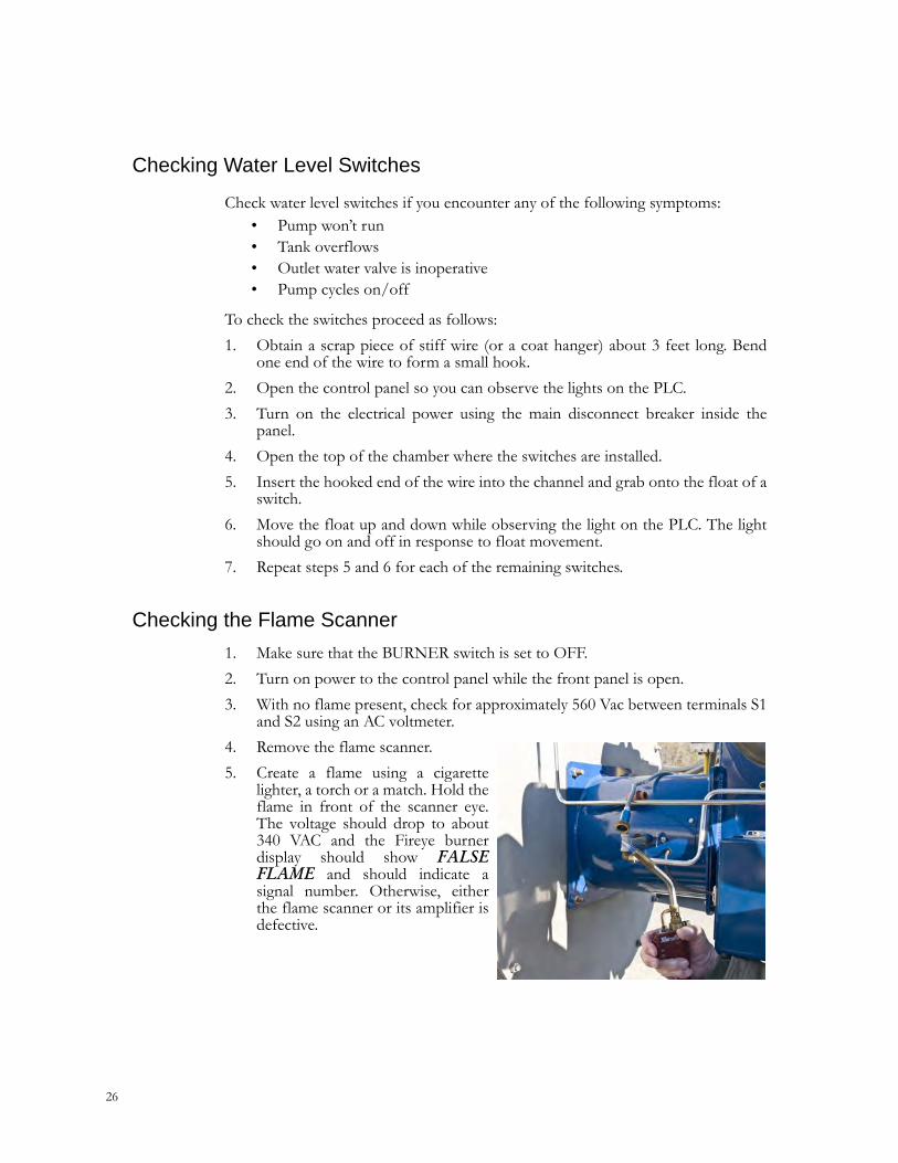
4. Remove the flame scanner.
5. Create a flame using a cigarettelighter, a torch or a match. Hold theflame in front of the scanner eye.The voltage should drop to about340 VAC and the Fireye burnerdisplay should show FALSEFLAME and should indicate asignal number. Otherwise, eitherthe flame scanner or its amplifier isdefective.
C18-054, CEI HHW-80 ECOHEAT
27
Checking the Pilot Gas Pressure Regulator
1. Connect a manometer to the tee of the pilot gas line where it enters theburner.
2. Open the control panel and gain access to the Fireye burner control.
3. Turn on power to the control panel while the front panel is open.
4. Set BURNER switch to ON and let the heater start through its purge cycle.
5. Wait for the burner display to show IGNITION TIMING. Quickly place theswitch marked CHECK/RUN on bottom of Fireye burner control to theCHECK position. This will hold the timing sequence while you check/adjustthe regulator.
6. Check that the manometer indicates approximately 3 inches of W.C. or asspecified for your burner in the burner manual. If not, adjust screw on theregulator to attain the recommended setting.
7. Place switch marked CHECK/RUN on bottom of Fireye burner control backto RUN. The timing sequence should continue and operation should benormal.
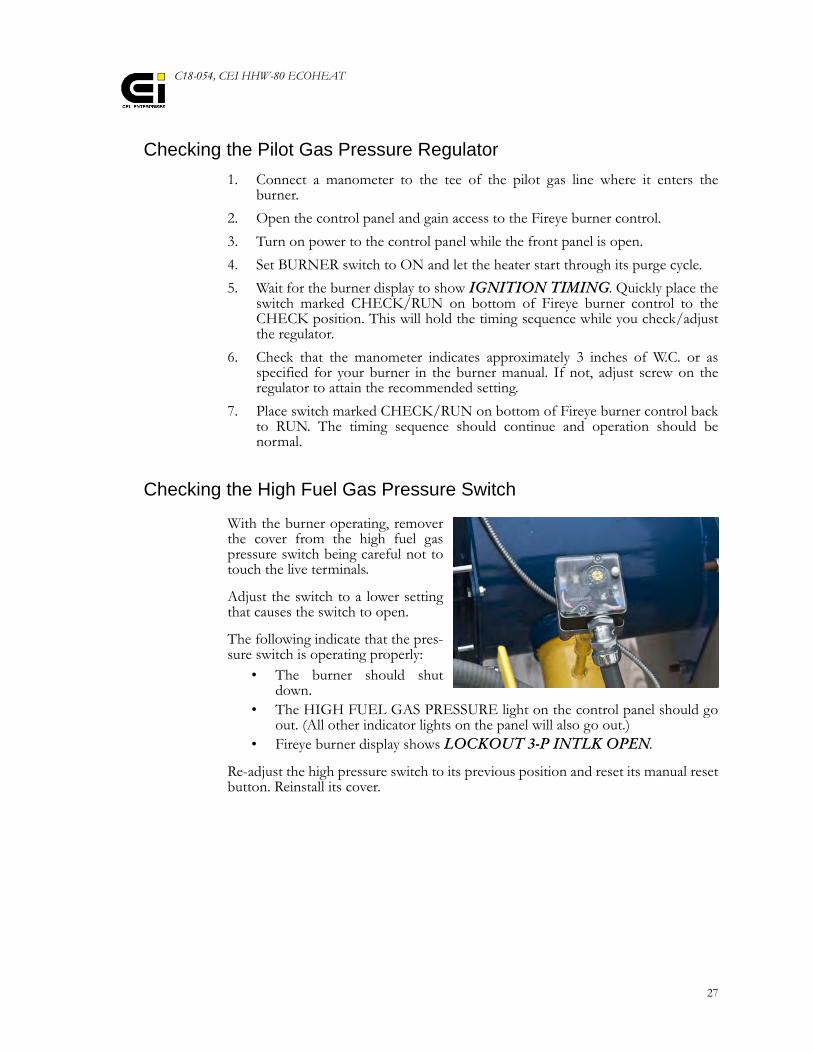
Checking the High Fuel Gas Pressure Switch
With the burner operating, removerthe cover from the high fuel gaspressure switch being careful not totouch the live terminals.
Adjust the switch to a lower settingthat causes the switch to open.
The following indicate that the pres-sure switch is operating properly:
• The burner should shutdown.
• The HIGH FUEL GAS PRESSURE light on the control panel should goout. (All other indicator lights on the panel will also go out.)
• Fireye burner display shows LOCKOUT 3-P INTLK OPEN.
Re-adjust the high pressure switch to its previous position and reset its manual resetbutton. Reinstall its cover.
28
Checking the Low Fuel Gas Pressure Switch
Shut off the main gas manual shutoff valve and set BURNER switch to ON.Remove the plug from the tee fitting below the pressure switch allowing gas toescape. The following reactions should occur, indicating that the switch is operatingproperly:
• LOW FUEL GAS PRESSURE light on control panel should be the firstlight to go out. (Subsequent indicator lights on the panel will also go out.)
• Fireye burner display shows LOCKOUT 3-P INTLK OPEN.
Reinstall plug in tee fitting. Slowly re-open the main gas manual shutoff valve.
Reset the low fuel gas pressure switchusing its manual reset button. Reset theFireye control.
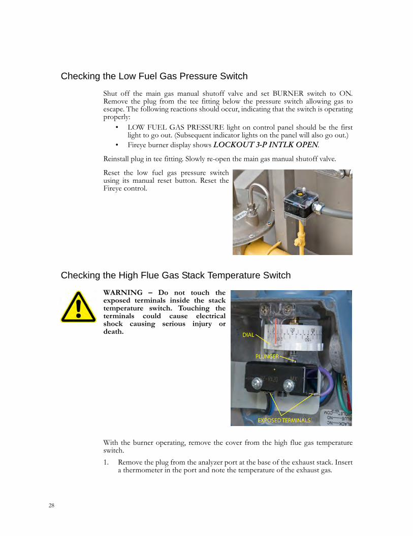
Checking the High Flue Gas Stack Temperature Switch
WARNING – Do not touch theexposed terminals inside the stacktemperature switch. Touching theterminals could cause electricalshock causing serious injury ordeath.
With the burner operating, remove the cover from the high flue gas temperatureswitch.
1. Remove the plug from the analyzer port at the base of the exhaust stack. Inserta thermometer in the port and note the temperature of the exhaust gas.
C18-054, CEI HHW-80 ECOHEAT
29
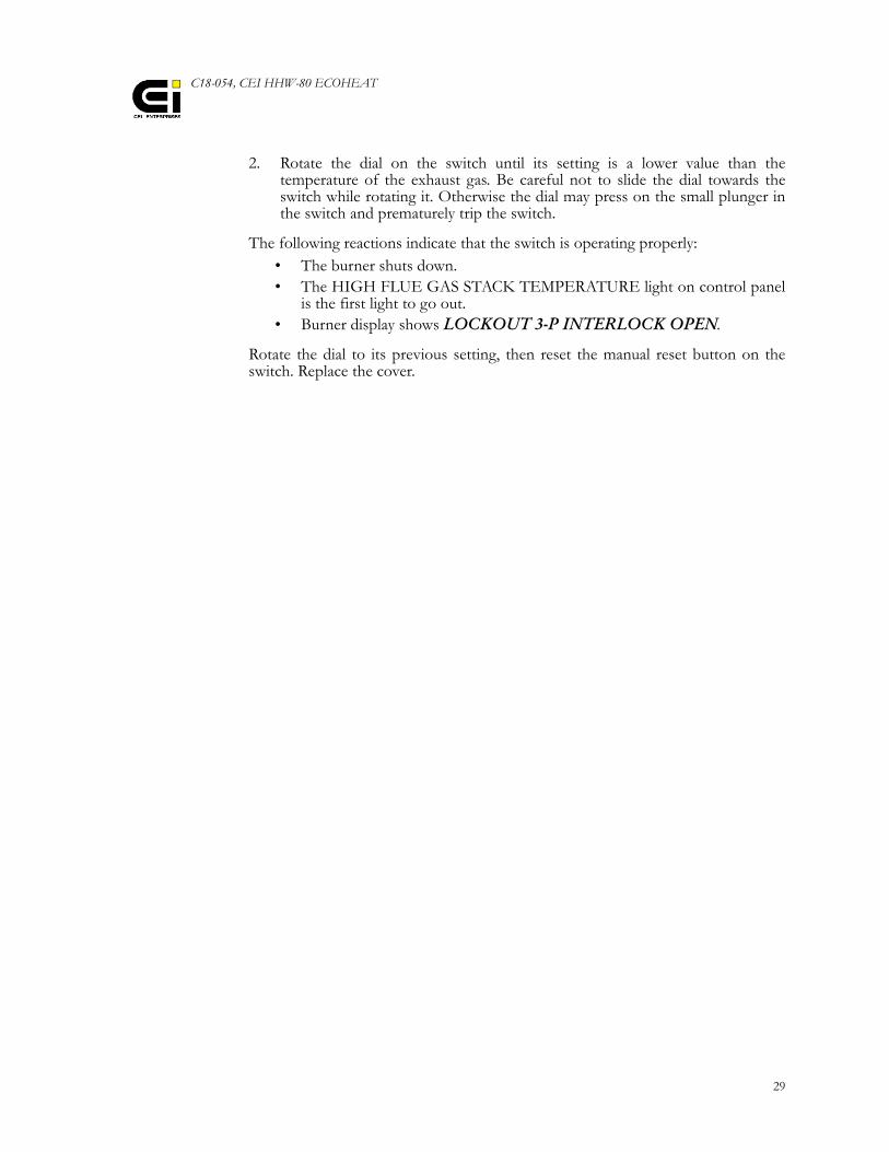
2. Rotate the dial on the switch until its setting is a lower value than thetemperature of the exhaust gas. Be careful not to slide the dial towards theswitch while rotating it. Otherwise the dial may press on the small plunger inthe switch and prematurely trip the switch.
The following reactions indicate that the switch is operating properly:• The burner shuts down.• The HIGH FLUE GAS STACK TEMPERATURE light on control panel
is the first light to go out.• Burner display shows LOCKOUT 3-P INTERLOCK OPEN.
Rotate the dial to its previous setting, then reset the manual reset button on theswitch. Replace the cover.
30
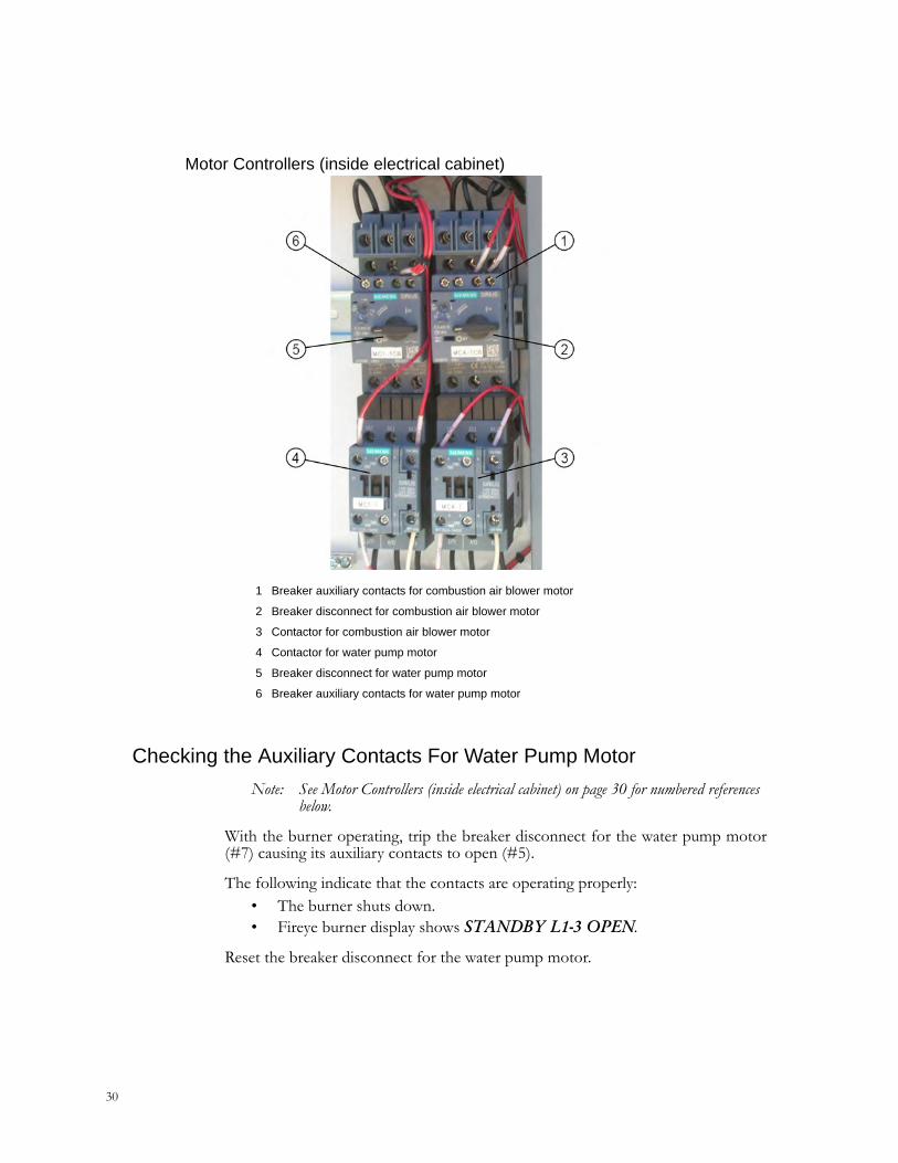
Motor Controllers (inside electrical cabinet)
Checking the Auxiliary Contacts For Water Pump Motor
Note: See Motor Controllers (inside electrical cabinet) on page 30 for numbered references below.
With the burner operating, trip the breaker disconnect for the water pump motor(#7) causing its auxiliary contacts to open (#5).
The following indicate that the contacts are operating properly:• The burner shuts down.• Fireye burner display shows STANDBY L1-3 OPEN.
Reset the breaker disconnect for the water pump motor.
1 Breaker auxiliary contacts for combustion air blower motor
2 Breaker disconnect for combustion air blower motor
3 Contactor for combustion air blower motor
4 Contactor for water pump motor
5 Breaker disconnect for water pump motor
6 Breaker auxiliary contacts for water pump motor
C18-054, CEI HHW-80 ECOHEAT
31
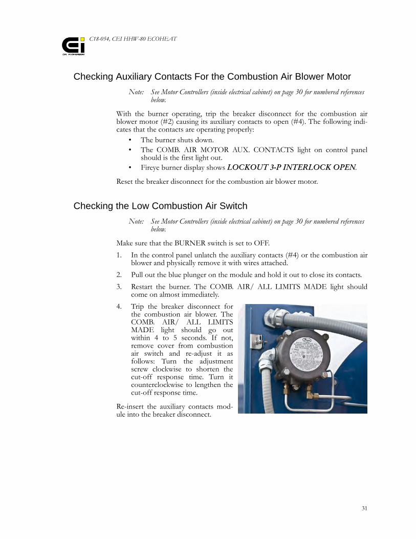
Checking Auxiliary Contacts For the Combustion Air Blower Motor
Note: See Motor Controllers (inside electrical cabinet) on page 30 for numbered references below.
With the burner operating, trip the breaker disconnect for the combustion airblower motor (#2) causing its auxiliary contacts to open (#4). The following indi-cates that the contacts are operating properly:
• The burner shuts down.• The COMB. AIR MOTOR AUX. CONTACTS light on control panel
should is the first light out.• Fireye burner display shows LOCKOUT 3-P INTERLOCK OPEN.
Reset the breaker disconnect for the combustion air blower motor.
Checking the Low Combustion Air Switch
Note: See Motor Controllers (inside electrical cabinet) on page 30 for numbered references below.
Make sure that the BURNER switch is set to OFF.
1. In the control panel unlatch the auxiliary contacts (#4) or the combustion airblower and physically remove it with wires attached.
2. Pull out the blue plunger on the module and hold it out to close its contacts.
3. Restart the burner. The COMB. AIR/ ALL LIMITS MADE light shouldcome on almost immediately.
4. Trip the breaker disconnect forthe combustion air blower. TheCOMB. AIR/ ALL LIMITSMADE light should go outwithin 4 to 5 seconds. If not,remove cover from combustionair switch and re-adjust it asfollows: Turn the adjustmentscrew clockwise to shorten thecut-off response time. Turn itcounterclockwise to lengthen thecut-off response time.
Re-insert the auxiliary contacts mod-ule into the breaker disconnect.
Maintenance Schedule
32
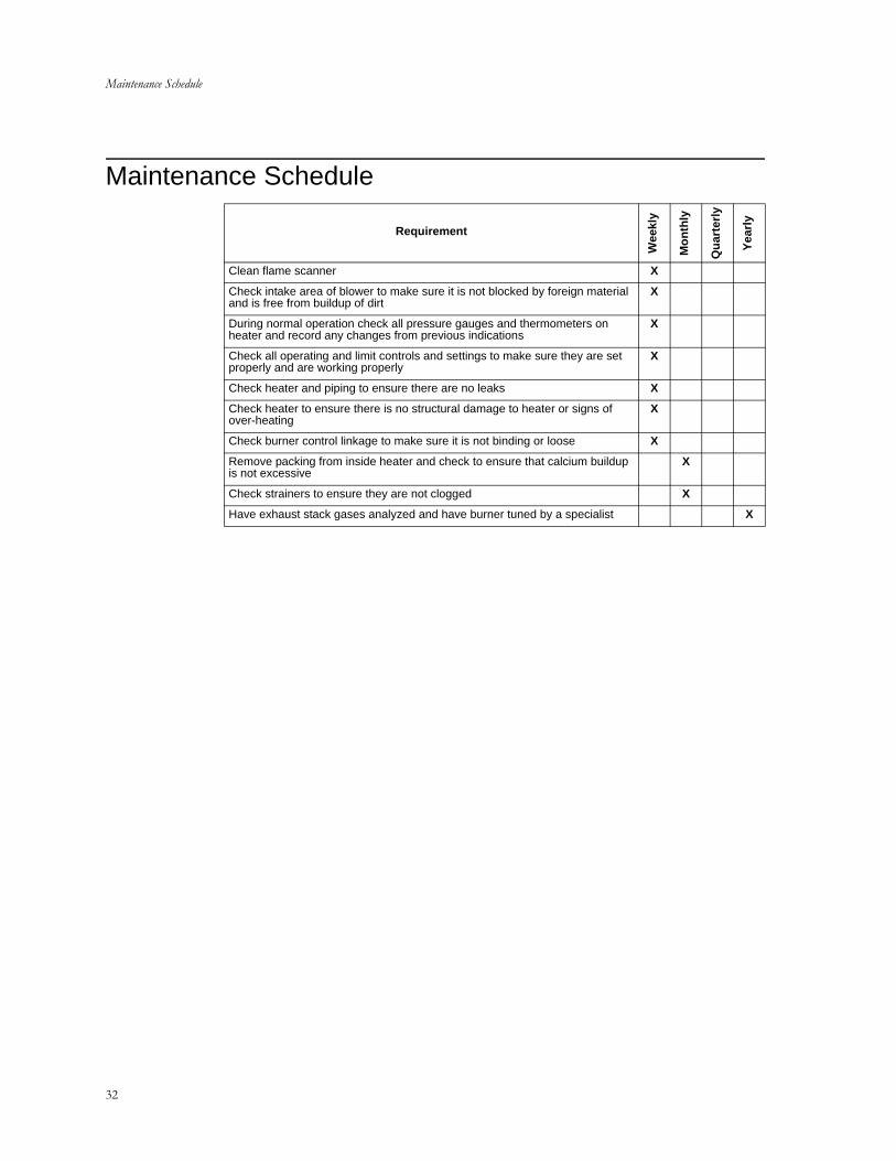
Maintenance Schedule
Requirement
Wee
kly
Mo
nth
ly
Qu
arte
rly
Yea
rly
Clean flame scanner X
Check intake area of blower to make sure it is not blocked by foreign material and is free from buildup of dirt
X
During normal operation check all pressure gauges and thermometers on heater and record any changes from previous indications
X
Check all operating and limit controls and settings to make sure they are set properly and are working properly
X
Check heater and piping to ensure there are no leaks X
Check heater to ensure there is no structural damage to heater or signs of over-heating
X
Check burner control linkage to make sure it is not binding or loose X
Remove packing from inside heater and check to ensure that calcium buildup is not excessive
X
Check strainers to ensure they are not clogged X
Have exhaust stack gases analyzed and have burner tuned by a specialist X
C18-054, CEI HHW-80 ECOHEAT Troubleshooting
33
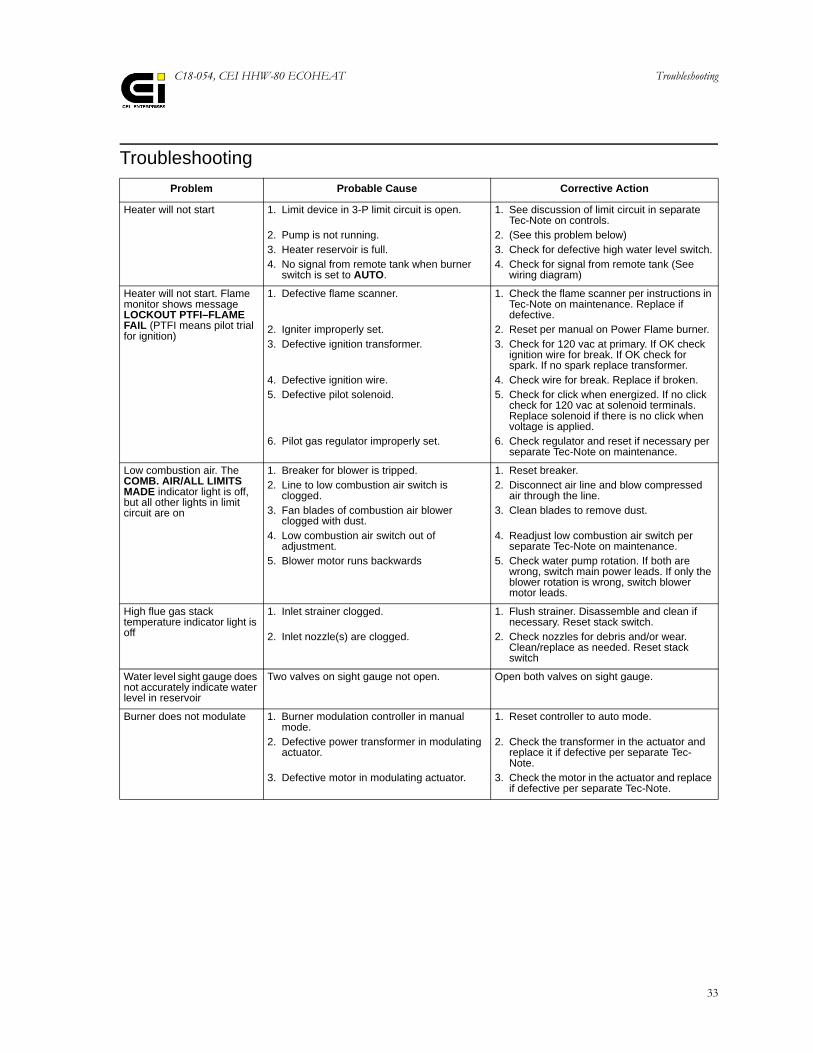
Troubleshooting
Problem Probable Cause Corrective Action
Heater will not start 1. Limit device in 3-P limit circuit is open.
2. Pump is not running.3. Heater reservoir is full.4. No signal from remote tank when burner
switch is set to AUTO.
1. See discussion of limit circuit in separate Tec-Note on controls.
2. (See this problem below)3. Check for defective high water level switch.4. Check for signal from remote tank (See
wiring diagram)
Heater will not start. Flame monitor shows message LOCKOUT PTFI–FLAME FAIL (PTFI means pilot trial for ignition)
1. Defective flame scanner.
2. Igniter improperly set.3. Defective ignition transformer.
4. Defective ignition wire.5. Defective pilot solenoid.
6. Pilot gas regulator improperly set.
1. Check the flame scanner per instructions in Tec-Note on maintenance. Replace if defective.
2. Reset per manual on Power Flame burner.3. Check for 120 vac at primary. If OK check
ignition wire for break. If OK check for spark. If no spark replace transformer.
4. Check wire for break. Replace if broken.5. Check for click when energized. If no click
check for 120 vac at solenoid terminals. Replace solenoid if there is no click when voltage is applied.
6. Check regulator and reset if necessary per separate Tec-Note on maintenance.
Low combustion air. The COMB. AIR/ALL LIMITS MADE indicator light is off, but all other lights in limit circuit are on
1. Breaker for blower is tripped.2. Line to low combustion air switch is
clogged.3. Fan blades of combustion air blower
clogged with dust.4. Low combustion air switch out of
adjustment.5. Blower motor runs backwards
1. Reset breaker.2. Disconnect air line and blow compressed
air through the line.3. Clean blades to remove dust.
4. Readjust low combustion air switch per separate Tec-Note on maintenance.
5. Check water pump rotation. If both are wrong, switch main power leads. If only the blower rotation is wrong, switch blower motor leads.
High flue gas stack temperature indicator light is off
1. Inlet strainer clogged.
2. Inlet nozzle(s) are clogged.
1. Flush strainer. Disassemble and clean if necessary. Reset stack switch.
2. Check nozzles for debris and/or wear. Clean/replace as needed. Reset stack switch
Water level sight gauge does not accurately indicate water level in reservoir
Two valves on sight gauge not open. Open both valves on sight gauge.
Burner does not modulate 1. Burner modulation controller in manual mode.
2. Defective power transformer in modulating actuator.
3. Defective motor in modulating actuator.
1. Reset controller to auto mode.
2. Check the transformer in the actuator and replace it if defective per separate Tec-Note.
3. Check the motor in the actuator and replace if defective per separate Tec-Note.
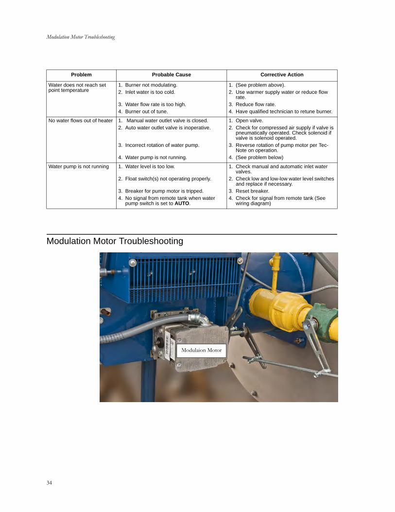
Modulation Motor Troubleshooting
34
Modulation Motor Troubleshooting
Water does not reach set point temperature
1. Burner not modulating.2. Inlet water is too cold.
3. Water flow rate is too high.4. Burner out of tune.
1. (See problem above).2. Use warmer supply water or reduce flow
rate.3. Reduce flow rate.4. Have qualified technician to retune burner.
No water flows out of heater 1. Manual water outlet valve is closed.2. Auto water outlet valve is inoperative.
3. Incorrect rotation of water pump.
4. Water pump is not running.
1. Open valve.2. Check for compressed air supply if valve is
pneumatically operated. Check solenoid if valve is solenoid operated.
3. Reverse rotation of pump motor per Tec-Note on operation.
4. (See problem below)
Water pump is not running 1. Water level is too low.
2. Float switch(s) not operating properly.
3. Breaker for pump motor is tripped.4. No signal from remote tank when water
pump switch is set to AUTO.
1. Check manual and automatic inlet water valves.
2. Check low and low-low water level switches and replace if necessary.
3. Reset breaker.4. Check for signal from remote tank (See
wiring diagram)
Problem Probable Cause Corrective Action
Modulaion Motor
C18-054, CEI HHW-80 ECOHEAT Modulation Motor Troubleshooting
35
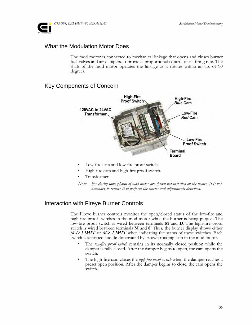
What the Modulation Motor Does
The mod motor is connected to mechanical linkage that opens and closes burnerfuel valves and air dampers. It provides proportional control of its firing rate. Theshaft of the mod motor operates the linkage as it rotates within an arc of 90degrees.
Key Components of Concern
• Low-fire cam and low-fire proof switch.• High-fire cam and high-fire proof switch.• Transformer.
Note: For clarity some photos of mod motor are shown not installed on the heater. It is not necessary to remove it to perform the checks and adjustments described.
Interaction with Fireye Burner Controls
The Fireye burner controls monitor the open/closed status of the low-fire andhigh-fire proof switches in the mod motor while the burner is being purged. Thelow-fire proof switch is wired between terminals M and D. The high-fire proofswitch is wired between terminals M and 8. Thus, the burner display shows eitherM-D LIMIT or M-8 LIMIT when indicating the status of these switches. Eachswitch is activated and de-deactivated by its own rotating cam in the mod motor.
• The low-fire proof switch remains in its normally closed position while thedamper is fully closed. After the damper begins to open, the cam opens theswitch.
• The high-fire cam closes the high-fire proof switch when the damper reaches apreset open position. After the damper begins to close, the cam opens theswitch.
Modulation Motor Troubleshooting
36
Interaction with Modulation Controller
The modulation controller controls the mod motor using a circuit that provides anoutput of 4 to 20 mA after the burner is lit and operating. With a 4 mA signal themod motor should be in the low-fire position with the damper fully closed. With a20 mA signal the mod motor should open the damper to the high-fire position.
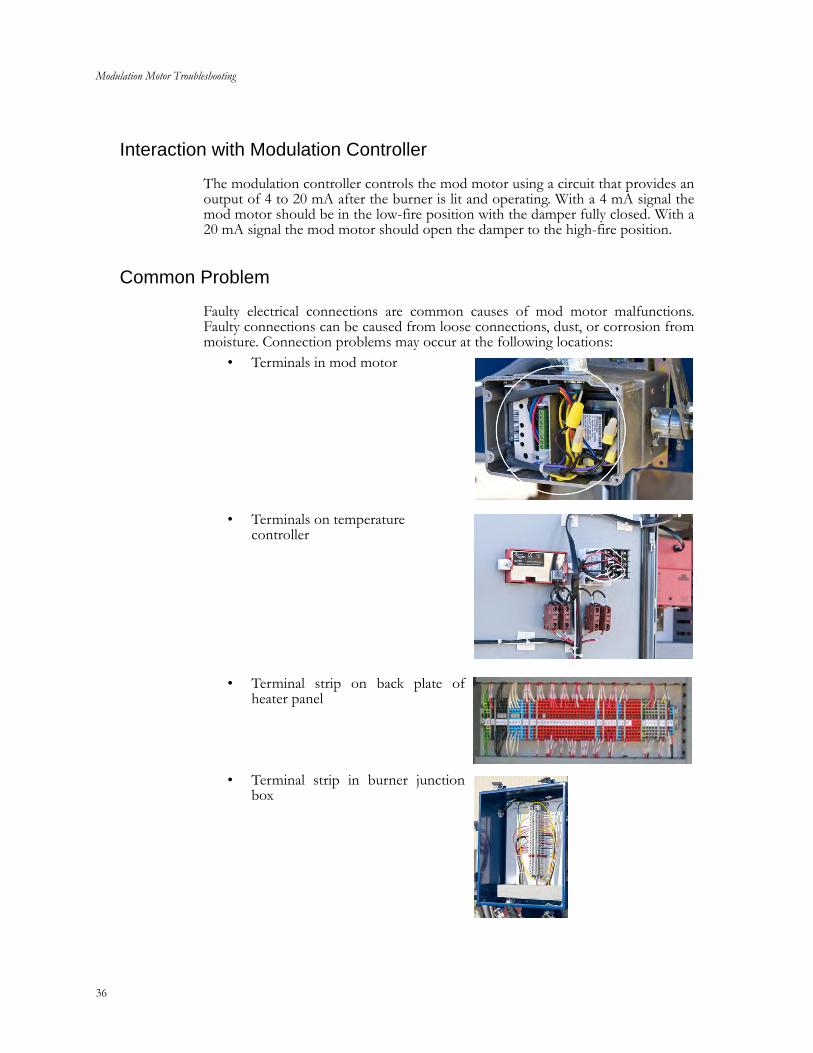
Common Problem
Faulty electrical connections are common causes of mod motor malfunctions.Faulty connections can be caused from loose connections, dust, or corrosion frommoisture. Connection problems may occur at the following locations:
• Terminals in mod motor
• Terminals on temperature controller
• Terminal strip on back plate ofheater panel
• Terminal strip in burner junctionbox
C18-054, CEI HHW-80 ECOHEAT Modulation Motor Troubleshooting
37
Other Problems• Cam Slippage• Transformer Failure
Symptoms of Problems• Mod motor fails to move when burner is first turned on.• Burner display indicates abnormal status of either M-D LIMIT or
M-8 LIMIT.• Mod motor fails to operate the linkage.• Modulation controller fails to modulate the mod motor.
Remedy for Faulty Electrical Connections
All wire connections that pertain to the mod motor have either screw terminals orcage-clamp spring terminals.
• On screw terminal connections use a screwdriver to slightly loosen thescrews and retighten them.
• On cage clamps connections push on the wire, wiggle it and then pull on itto make sure it is held tightly.
Checking and Resetting Cams
1. Remove the top cover so that you can gain access to the tops of the cams.
2. Make sure the shaft of the mod motor is rotated to its position for a fullyclosed damper.
3. Check positions of the target lobes of the cams. The cams have click stops thathold them in position. Repositioning a cam does not turn the drive shaft of themod motor.
4. You may be able to rotate the cams with your fingers. Otherwise insert theblade of a screwdriver in the slots of the cam and rotate them.
Modulation Motor Troubleshooting
38
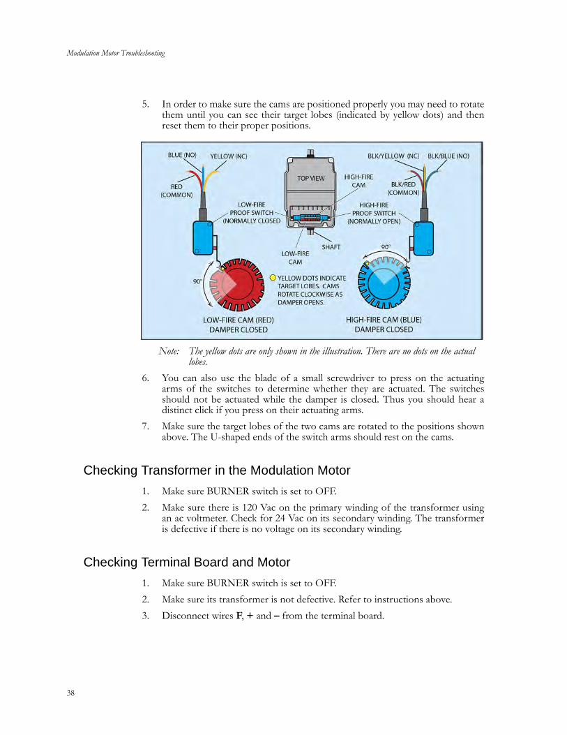
5. In order to make sure the cams are positioned properly you may need to rotatethem until you can see their target lobes (indicated by yellow dots) and thenreset them to their proper positions.
Note: The yellow dots are only shown in the illustration. There are no dots on the actual lobes.
6. You can also use the blade of a small screwdriver to press on the actuatingarms of the switches to determine whether they are actuated. The switchesshould not be actuated while the damper is closed. Thus you should hear adistinct click if you press on their actuating arms.
7. Make sure the target lobes of the two cams are rotated to the positions shownabove. The U-shaped ends of the switch arms should rest on the cams.
Checking Transformer in the Modulation Motor
1. Make sure BURNER switch is set to OFF.
2. Make sure there is 120 Vac on the primary winding of the transformer usingan ac voltmeter. Check for 24 Vac on its secondary winding. The transformeris defective if there is no voltage on its secondary winding.
Checking Terminal Board and Motor
1. Make sure BURNER switch is set to OFF.
2. Make sure its transformer is not defective. Refer to instructions above.
3. Disconnect wires F, + and – from the terminal board.
C18-054, CEI HHW-80 ECOHEAT Modulation Motor Troubleshooting
39
4. Connect a short jumper wire from terminals – to F. The motor of the actuatorshould go to high-fire, indicating that the terminal board and motor are okay.If the motor moves, remove jumper and reconnect the F, + and – wires.Otherwise, remove jumper only and continue with the following steps.
5. Set main disconnect switch on door of control panel to OFF.
6. Remove the two brown wires from terminals T1 and T2. Remove terminalboard.
7. Reconnect one brown wire to the connector prong marked T1 on the circuitboard. Connect the other brown wire to the connector prong marked T2 onthe circuit board.
8. Temporarily connect a short jumper wire from the connector prong marked –to prong marked F.
9. Set main disconnect switch on door of control panel to ON.
10. If motor moves it is good, but terminal board is defective and must bereplaced. If motor does not move replace motor.

Modulation Motor Troubleshooting
40
Gas O
nly HH
W B
urnersH
HW
Burner – L
eft Side
41
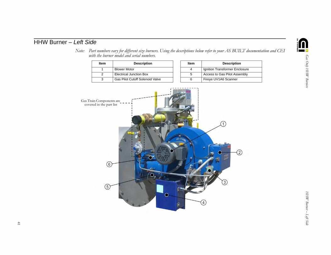
HHW Burner – Left SideNote: Part numbers vary for different size burners. Using the descriptions below refer to your AS BUILT documentation and CEI
with the burner model and serial numbers.
Item Description Item Description
1 Blower Motor 4 Ignition Transformer Enclosure
2 Electrical Junction Box 5 Access to Gas Pilot Assembly
3 Gas Pilot Cutoff Solenoid Valve 6 Fireye UV1A6 Scanner
Gas Train Components are covered in the part list
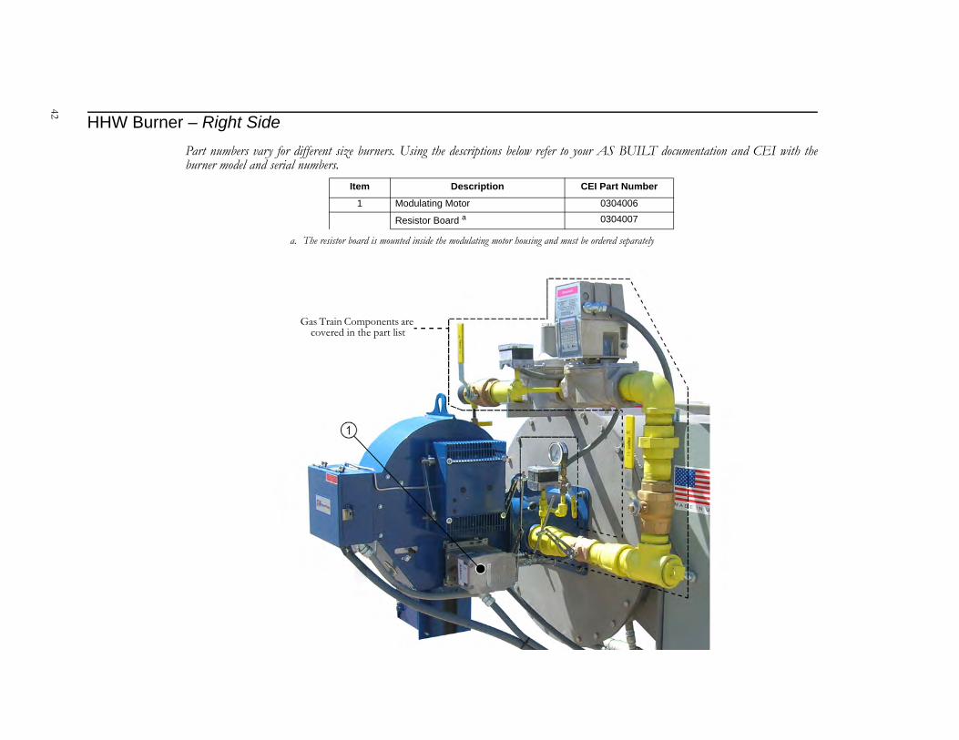
42
HHW Burner – Right SidePart numbers vary for different size burners. Using the descriptions below refer to your AS BUILT documentation and CEI with theburner model and serial numbers.
Item Description CEI Part Number
1 Modulating Motor 0304006
Resistor Board a
a. The resistor board is mounted inside the modulating motor housing and must be ordered separately
0304007
Gas Train Components are covered in the part list
Gas O
nly HH
W B
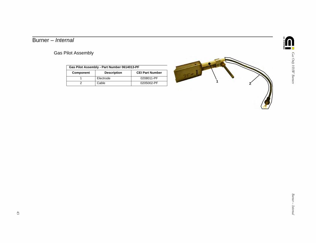
urnersBurner – Internal
43
Burner – Internal
Gas Pilot Assembly
Gas Pilot Assembly - Part Number 0614013-PF
Component Description CEI Part Number
1 Electrode 0208011-PF
2 Cable 0205002-PF 12

44
45
C18-054, CEI HHW-80 ECOHEAT
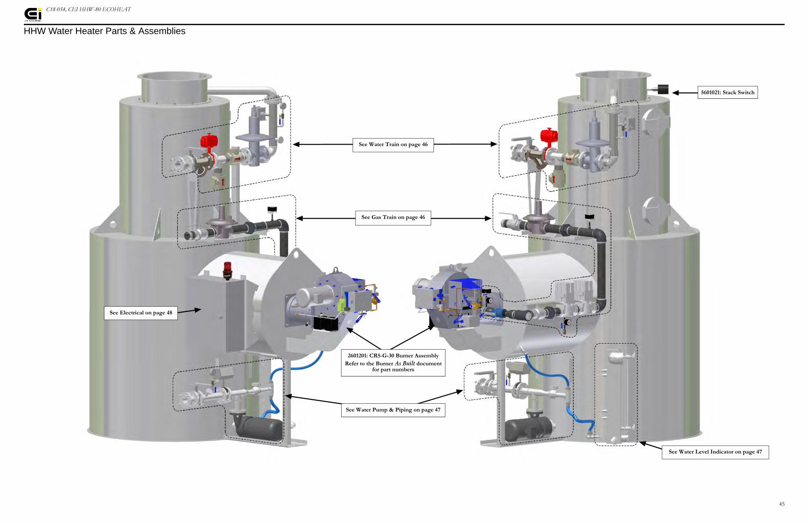
HHW Water Heater Parts & Assemblies
2601201: CR5-G-30 Burner AssemblyRefer to the Burner As Built document
for part numbers
5601021: Stack Switch
See Gas Train on page 46
See Water Train on page 46
See Water Pump & Piping on page 47
See Water Level Indicator on page 47
See Electrical on page 48
46
C18-054, CEI HHW-80 ECOHEAT
Water Train & Gas Train Components
Water Train Gas TrainItem Part # Description Item Part # Description
A 1303302 3" Butterfly Valve w/Handle A 980450 3" Main Gas Shutoff Ball Valve
B 1204042 3" Y Strainer B 301100 3" Main Gas Pressure Regulator
C 1301124 3" Bray Butterfly Valve C 161000 Low Gas Pressure Switch
D 1301154 3" Swing Check Valve D 190700 6 - 14 Second Asco AH2E212A1 Actuator
E 1301125 3" 150# Pressure Reducing Valve E 190900 Asco AH2E212S4 Actuator w/P.O.C.
F 0402030 0-250° F 3" x 2½" Thermometer F 194400 6-14 Second Motorized Gas Valve
G 1303081 ¼" Bronze Valve G 192800 6-14 Second Motorized Gas Valve
H 0202152 0 - 30 PSI Pressure Switch H 0401008 0 - 15 H20 Gas Gauge
J 0403024 0 - 30 PSI Pressure Gauge J 1302081 ¼" Bronze Valve
K 1304011 3" Main Gas Shutoff Ball Valve
L 1601100 High Gas Pressure Switch
47
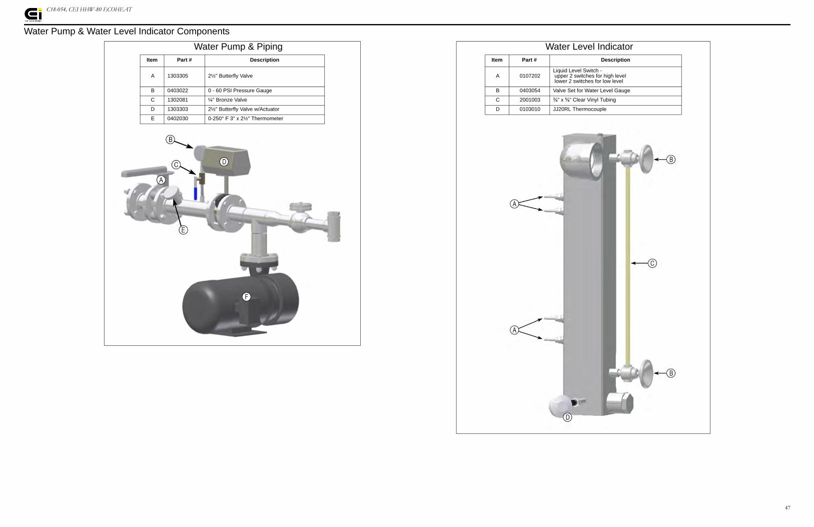
C18-054, CEI HHW-80 ECOHEAT
Water Pump & Water Level Indicator Components
Water Pump & Piping Water Level IndicatorItem Part # Description Item Part # Description
A 1303305 2½" Butterfly Valve A 0107202Liquid Level Switch - upper 2 switches for high level lower 2 switches for low level
B 0403022 0 - 60 PSI Pressure Gauge B 0403054 Valve Set for Water Level Gauge
C 1302081 ¼" Bronze Valve C 2001003 ⅜" x ⅝" Clear Vinyl Tubing
D 1303303 2½" Butterfly Valve w/Actuator D 0103010 JJ20RL Thermocouple
E 0402030 0-250° F 3" x 2½" Thermometer
48
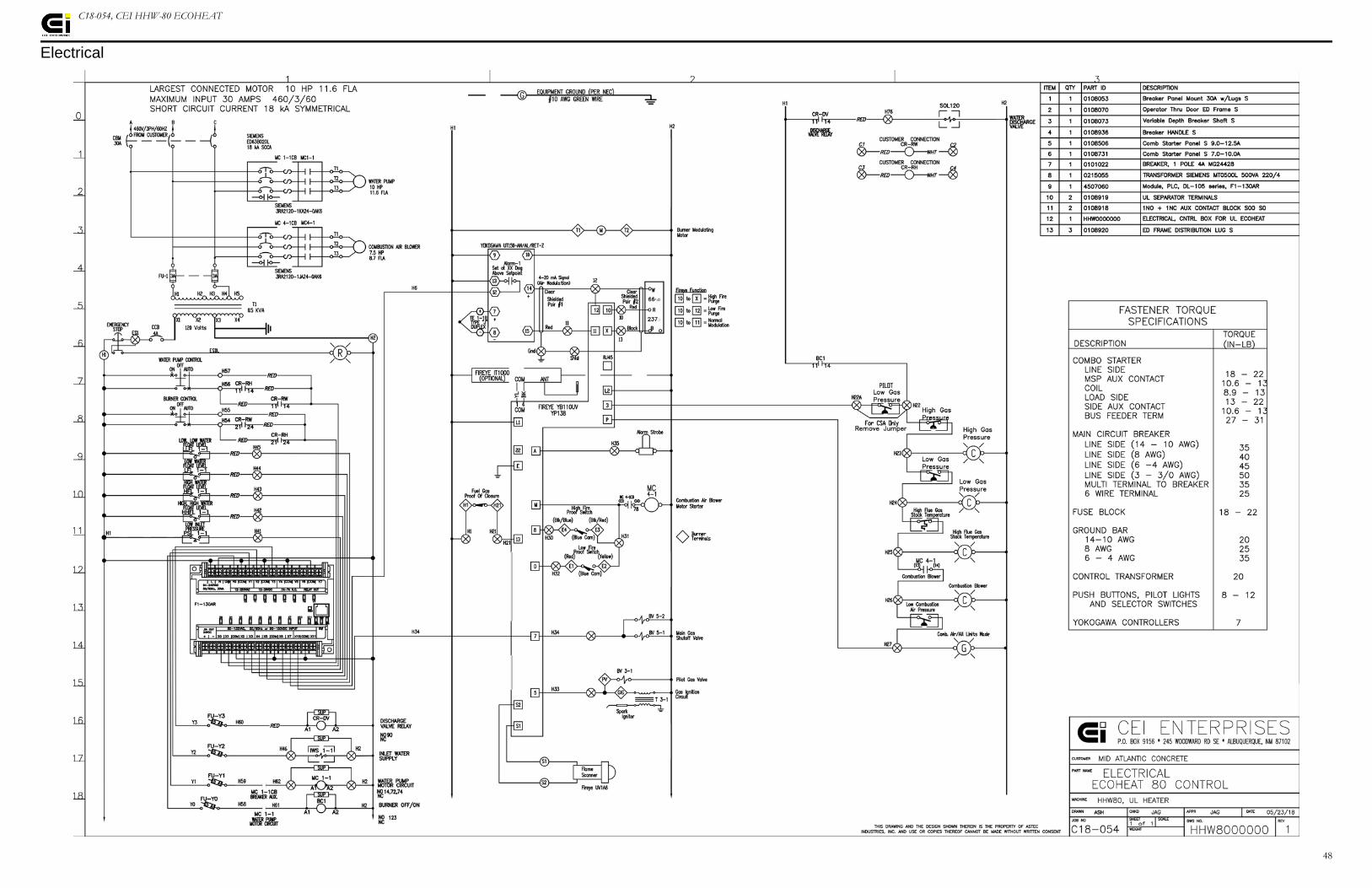
C18-054, CEI HHW-80 ECOHEAT
Electrical
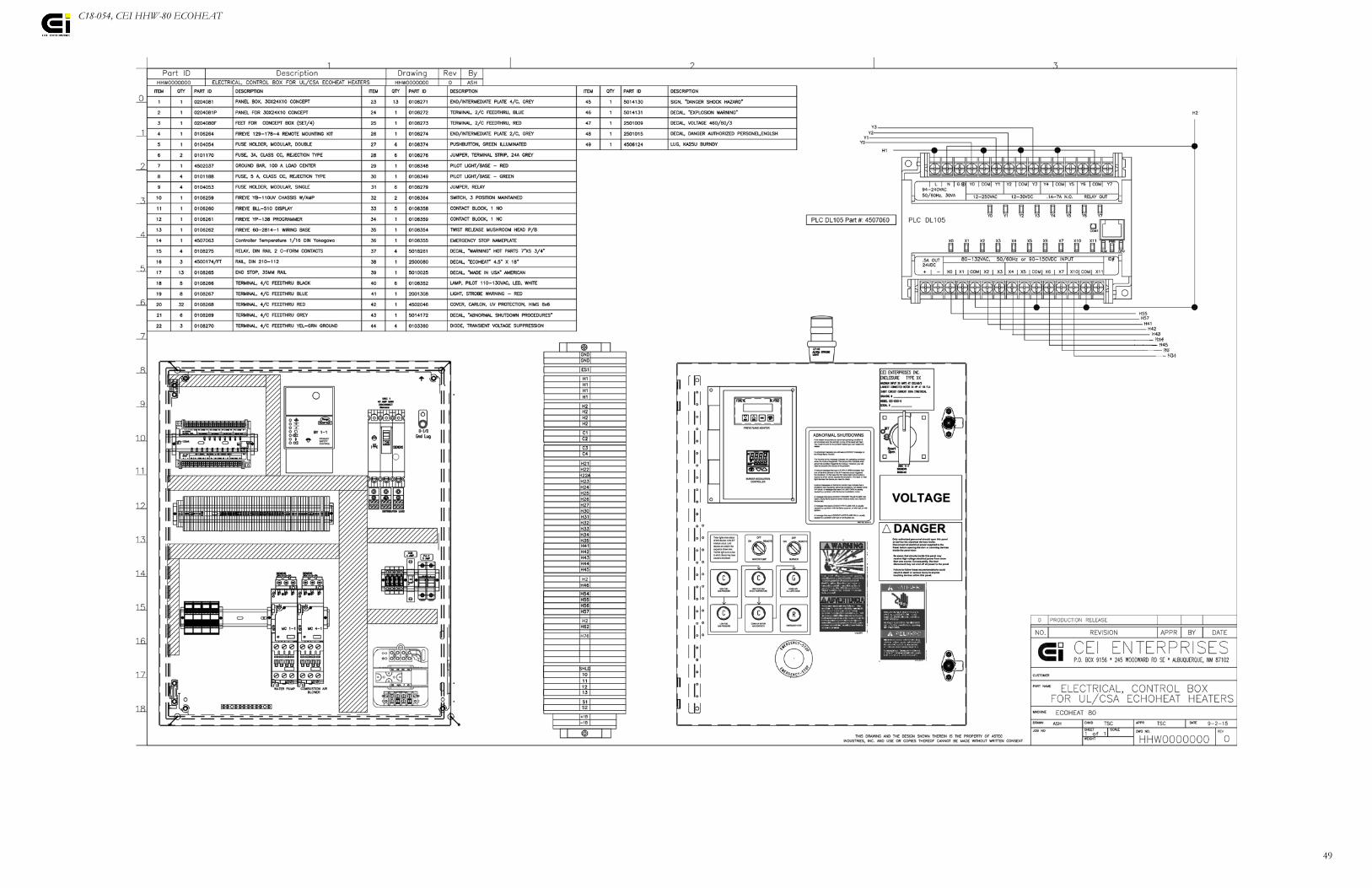
49
C18-054, CEI HHW-80 ECOHEAT

50
C18-054, CEI HHW-80 ECOHEAT

C18-054, CEI HHW-80 ECOHEAT
Specifications

52
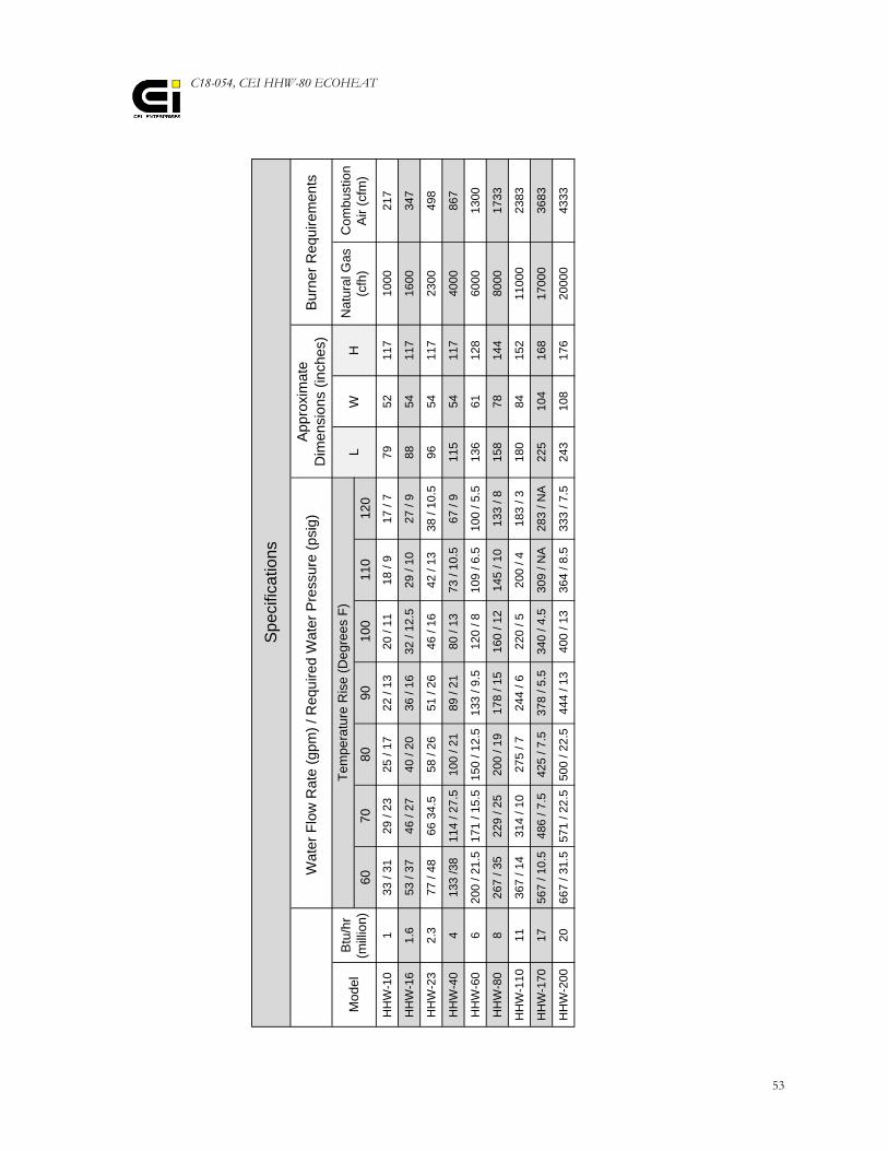
C18-054, CEI HHW-80 ECOHEAT
53
6070
8090
100
110
120
HH
W-1
01
33 /
3129
/ 23
25 /
1722
/ 13
20 /
1118
/ 9
17 /
779
5211
710
0021
7
HH
W-1
61.
653
/ 37
46 /
2740
/ 20
36 /
1632
/ 12
.529
/ 10
27 /
988
5411
716
0034
7
HH
W-2
32.
377
/ 48
66 3
4.5
58 /
2651
/ 26
46 /
1642
/ 13
38 /
10.5
9654
117
2300
498
HH
W-4
04
133
/38
114
/ 27.
510
0 / 2
189
/ 21
80 /
1373
/ 10
.567
/ 9
115
5411
740
0086
7
HH
W-6
06
200
/ 21.
517
1 / 1
5.5
150
/ 12.
513
3 / 9
.512
0 / 8
109
/ 6.5
100
/ 5.5
136
6112
860
0013
00
HH
W-8
08
267
/ 35
229
/ 25
200
/ 19
178
/ 15
160
/ 12
145
/ 10
133
/ 815
878
144
8000
1733
HH
W-1
1011
367
/ 14
314
/ 10
275
/ 724
4 / 6
220
/ 520
0 / 4
183
/ 318
084
152
1100
023
83
HH
W-1
7017
567
/ 10.
548
6 / 7
.542
5 / 7
.537
8 / 5
.534
0 / 4
.530
9 / N
A28
3 / N
A22
510
416
817
000
3683
HH
W-2
0020
667
/ 31.
557
1 / 2
2.5
500
/ 22.
544
4 / 1
340
0 / 1
336
4 / 8
.533
3 / 7
.524
310
817
620
000
4333
Nat
ural
Gas
(c
fh)
Com
bust
ion
Air
(cfm
)
Spe
cific
atio
ns
Wat
er F
low
Rat
e (g
pm) /
Req
uire
d W
ater
Pre
ssur
e (p
sig)
App
roxi
mat
eD
imen
sion
s (in
ches
)B
urne
r Req
uire
men
ts
Tem
pera
ture
Ris
e (D
egre
es F
)L
WH
Btu
/hr
(mill
ion)
Mod
el

54
C18-054, CEI HHW-80 ECOHEAT Contact Information
55
Contact Information
CEI ENTERPRISES, INC.An Astec CompanyP.O. Box 9156Albuquerque, New Mexico, U.S.A. 87119
CEI Service (General Contact)
Phone: (800) 545-4034 or (505) 842-5556Fax: (505) 243-1422www.ceienterprises.com
Departmental Contacts
Shanon HeathService ManagerCell: (505) 908-8794
Randall Carroll Engineering ManagerCell: (505) 401-8221
Johnny RomeroParts RepresentativeCell: (505) 235-2789

CEI ENTERPRISES, INC.An Astec Company
245 Woodward Road, SEAlbuquerque, New Mexico, U.S.A. 87102
C18-054, CEI HHW-80 ECOHEAT v 3.2.0815