hheeaatt aanndd mmaassss ttrraannssffeerr … data/heat transfer/study...for more information log on...
TRANSCRIPT

For more information log on www.brijrbedu.org
Brij Bhooshan Asst. Professor B.S.A College of Engg. & Technology, Mathura (India)
Copyright by Brij Bhooshan @ 2013 Page 1
HHeeaatt aanndd MMaassss TTrraannssffeerr
CChhaapptteerr -- 77 EEmmppaarriiccaall RReellaattiioonn FFoorr
FFrreeee CCoonnvveeccttiioonn
PPrreeppaarreedd BByy
BBrriijj BBhhoooosshhaann
AAsssstt.. PPrrooffeessssoorr
BB.. SS.. AA.. CCoolllleeggee ooff EEnngggg.. AAnndd TTeecchhnnoollooggyy
MMaatthhuurraa,, UUttttaarr PPrraaddeesshh,, ((IInnddiiaa))
SSuuppppoorrtteedd BByy::
PPuurrvvii BBhhoooosshhaann
In This Chapter We Cover the Following Topics
Art. Content Page
7.1 Concept of Buoyancy Force 2
7.2 Dimensionless Parameters of Natural Convection 3
7.3 An Approximate Analysis of Laminar Natural Convection on a Vertical Plate 5
7.4 Free Convection from Vertical Planes and Cylinders 9
7.5 Free Convection from Horizontal Cylinders 12
7.6 Free Convection from Horizontal Plates 12
7.7 Free Convection from Spheres 13
7.8 Free Convection in Enclosed Spaces 13
7.9 Rotating Cylinders, Disks and Spheres 17
7.10 Combined Forced and Natural Convection 18
References:
1- J. P. Holman, Heat Transfer, 9th Edn, MaGraw-Hill, New York, 2002.
2- James R. Welty, Charles E. Wicks, Robert E. Wilson, Gregory L. Rorrer
Fundamentals of Momentum, Heat, and Mass Transfer, 5th Edn, John Wiley & Sons,
Inc., 2008.
3- F. Kreith and M. S. Bohn, Principal of Heat Transfer, 5th Edn, PWS Publishing Co.,
Boston, 1997.
4- P. K. Nag, Heat and Mass Transfer, 2nd Edn, MaGraw-Hill, New Delhi 2005.
Please welcome for any correction or misprint in the entire manuscript and your
valuable suggestions kindly mail us [email protected].

For more information log on www.brijrbedu.org
Brij Bhooshan Asst. Professor B.S.A College of Engg. & Technology, Mathura (India)
Copyright by Brij Bhooshan @ 2013 Page 2
2 Chapter 7: Emparical Relation for Free Convection
The flow velocity in free convection is much smaller than that encountered in forced
convection. Therefore, heat transfer by free convection is much smaller than that by
forced convection. Diagram 7.1 (a) illustrates the development of velocity field infront of
a hot vertical plate owing to the buoyancy force. The heated fluid in front of the hot plate
rises, entraining fluid from the quiescent outer region.
Diagram 7.1 (b) shows a cold vertical plate in a hot fluid, where the direction of motion
is reversed, the fluid in front of the plate being heavier moves vertically down, again
entraining fluid from the quiescent outer region.
Diagram 7.1 Laminar and turbulent velocity boundary layer for natural convection on a vertical plate
In both cases a velocity boundary layer is develops with a certain peak in it. The velocity
is zero both the plate surface and at the edge of boundary layer is laminar, then at a
certain distance from the leading edge the transition to turbulent layer occurs, and
finally a fully developed turbulent layer is established.
7.1 CONCEPT OF BUOYANCY FORCE
We now consider a fluid contained in the space between two parallel horizontal plates
(Diagram 7.2(a)).
Diagram 7.2
Suppose the lower plate is maintained at a temperature higher than that of the upper
plate (Tl > T2). A temperature gradient will be established in the vertical direction. The
layer will be top-heavy, since the density of the cold fluid at the top is higher than that
of the hot fluid at the bottom. If the temperature difference is increased beyond a certain
critical value, the viscous forces within the fluid can no longer sustain the buoyancy
forces, and a convection motion is set up.
Suppose in Diagram 7.2(b), the lower plate is cold and the upper plate is hot (i.e. T l <
T2). Here, the density of the top layer is less than that of the bottom layer. The fluid is
then always stable, and no natural convection currents are set up.
(a) Lower plate hot
Unstable fluid
Hot wall
Cold wall
(b) Lower plate hot
Stable
fluid
Cold wall
Hot wall
(a) Hot wall
Turbulent
Laminar
(b) Cold wall
Turbulent
Laminar

For more information log on www.brijrbedu.org
Brij Bhooshan Asst. Professor B.S.A College of Engg. & Technology, Mathura (India)
Copyright by Brij Bhooshan @ 2013 Page 3
3 Heat and Mass Transfer By Brij Bhooshan
Diagram 7.3 Buoyancy-driven flows on horizontal cold (Tw < T) and hot (Tw > T) plates,
(a) Top surface of cold plate, (b) bottom surface of cold plate, (c) top surface of hot plate and (d) bottom
surface of hot plate
Diagram 7.3 shows the directions of convection currents for horizontal plates, heated or
cooled, facing up or down.
7.2 DIMENSIONLESS PARAMETERS OF NATURAL CONVECTION
To develop the principal dimensionless parameters of natural convection, we consider
the natural convection on a vertical plate, as illustrated in Diagram 7.1. For simplicity
analysis, we assume that the boundary layer flow is steady and laminar. Since small
flow velocities are associated with natural convection, the viscous energy dissipation
term in the energy equation can be neglected. Then to governing continuity, momentum
and energy equations are obtained from the boundary layer equations, as derived in the
last chapter, and the appropriate buoyancy term is introduced in the momentum
equation:
Continuity:
Momentum:
Energy:
Here the term ρg on the right hand side of the momentum equation represents the
body force exerted on the fluid element in the negative x-direction.
For small temperature differences, the density ρ in the buoyancy term is considered to
vary with temperature, whereas the density appearing elsewhere in these equations is
considered constant. This is often referred to as Boussinesq approximation.
To determine the pressure gradient term dp/dx, the x-momentum equation, Eq. (7.2)
is evaluated at the edge of the velocity boundary layer, where u → 0 and ρ → ρ. We
obtain
where ρ is the fluid density outside the boundary layer. Then the term ρg dP/dx
appearing in the momentum equation, Eq. (7.2) becomes
If β denotes the volumetric coefficient in thermal expansion of the fluid,
(a)
(b)
(d)
(c)

For more information log on www.brijrbedu.org
Brij Bhooshan Asst. Professor B.S.A College of Engg. & Technology, Mathura (India)
Copyright by Brij Bhooshan @ 2013 Page 4
4 Chapter 7: Emparical Relation for Free Convection
Using equation (7.4) and (7.7)
To find the dimensionless parameters that governs heat transfer in natural convection.
Suppose
Using Eqns. (7.1) and (7.9)
Using Eqns. (7.2), (7.8) and (7.9)
Using Eqns. (7.3) and (7.9)
Here, the Reynolds and Prandtl numbers are defined as
The dimensionless group in the momentum equation can be rearranged as
where the Grashof number Gr is defined as
The Grashof number represents the ratio of the buoyancy force to the viscous force
acting on the fluid.
Equation (7.11) imply that when the effects of natural and forced convection are of
comparable magnitude, the Nusselt number depends on Re, Pr and Gr, or
The parameter Gr/Re2, defined by Eq. (5.13), is a measure of the relative importance of
natural convection in relation to forced convection.
When Gr/Re2 ≌ 1, natural and forced convection are of the same order of magnitude;
hence both must be considered.
If (Gr/Re2) << 1, flow is primarily by forced convection.
If (Gr/Re2) >> 1, natural convection becomes dominant and the Nusselt number depends
on Gr and Pr only:

For more information log on www.brijrbedu.org
Brij Bhooshan Asst. Professor B.S.A College of Engg. & Technology, Mathura (India)
Copyright by Brij Bhooshan @ 2013 Page 5
5 Heat and Mass Transfer By Brij Bhooshan
In natural convection, flow velocities are produced by the buoyancy forces only; hence
there are no externally induced flow velocities. As a result, the Nusselt number does not
depend on the Reynolds number.
Sometimes another dimensionless parameter, called the Rayleigh number (Ra), which is
defined as
The Grashof number to correlate heat transfer in natural convection. Then the Nusselt
number relation (Eq. (7.16)), becomes
For three-dimensional shapes such as short cylinders and blocks the characteristic
length L may be determined from
where Lx is the height and Ly the average horizontal dimension of the body.
7.3 AN APPROXIMATE ANALYSIS OF LAMINAR NATURAL CONVECTION ON
A VERTICAL PLATE
Let us consider Tw and T be, respectively, the temperature of the wall surface and the
bulk temperature of the fluid (Diagram 7.4). The fluid moves upward along the plate for
Tw > T and flow downwards for Tw < T, as shown in Diagram 7.1. Within the boundary
layer temperature decrease from Tw to < T of the undisturbed or quiescent fluid outside
the heated region.
Diagram 7.4 Temperature and velocity profile for free convection on a hot vertical plate
Let θ = T T. When y = 0, θ = θw = Tw T, and when y = δ, θ = θ = 0. If y = 0, u = 0,
and if y = δ, u = 0.
The velocity and temperature profiles in the neighbourhood of the plate are shown. The
integral boundary layer equations for momentum and energy will be used to calculate
the heat transfer in natural convection.
Temperature profile
To solve the boundary layer equation, the temperature profile is approximated by a
parabolic equation of the form
At y = 0, T = Tw = C
At y = δ = δt, T = T, (∂T/∂y)y = δ = 0
Boundary layer
For more information log on www.brijrbedu.org
Brij Bhooshan Asst. Professor B.S.A College of Engg. & Technology, Mathura (India)
Copyright by Brij Bhooshan @ 2013 Page 6
6 Chapter 7: Emparical Relation for Free Convection
It is we assume δ = δt i.e. equal velocity and thermal boundary layer thicknesses.
Substituting in Eq. (7.20),
Therefore
The velocity profile may be assumed to be a cubical parabola given by
where u1 is a reference velocity and is a function of x.
At y = 0, u = 0.
At y = δ = δt, u = 0, ∂u/∂y = 0
Using the first boundary condition u = 0 = au1
Since u1 ≠ 0, d = 0
Now
At y = δ = δt, u = 0, ∂u/∂y = 0
From momentum equation,
Therefore
when y = 0, θ = θw, then we have
From Eqns. (7.23a), (7.23b) and (7.24a), we have

For more information log on www.brijrbedu.org
Brij Bhooshan Asst. Professor B.S.A College of Engg. & Technology, Mathura (India)
Copyright by Brij Bhooshan @ 2013 Page 7
7 Heat and Mass Transfer By Brij Bhooshan
where
The velocity profile given by
There is a certain value of y where u is maximum
After solving we get y = δ or δ/3.
Since u = 0 at y = δ, therefore, u will be maximum when y = δ/3.Therefore
Analysis
Let us consider a control volume differential element dx at a distance from the bottom
edge within the boundary layer as shown in Diagram 7.5.
Diagram 7.5 Control volume in the boundary layer
Momentum flux across BC is zero.
Rate of increase of momentum
= Forces acting on the element
Integrating is limited to δ, as before
Energy equation for volume element gives
L
C.V.
C
B

For more information log on www.brijrbedu.org
Brij Bhooshan Asst. Professor B.S.A College of Engg. & Technology, Mathura (India)
Copyright by Brij Bhooshan @ 2013 Page 8
8 Chapter 7: Emparical Relation for Free Convection
Integrating is limited to δ = δt,
Now
Substituting these values in momentum equation (7.27)
and energy equation
But u0 and δ are function of x. Suppose
Now using equation (7.29), then
Again energy equation (7.30)
Equation (7.31) and (7.32) are valid for any value of x.
Equating the corresponding component of x in Eq. (7.31) and (7.32), then
Put the values of m and n in Eq. (7.31) and (7.32),

For more information log on www.brijrbedu.org
Brij Bhooshan Asst. Professor B.S.A College of Engg. & Technology, Mathura (India)
Copyright by Brij Bhooshan @ 2013 Page 9
9 Heat and Mass Transfer By Brij Bhooshan
Now using Eqns. (7.33a) and (7.33b),
Heat flux
As x increases, δ also increases.
h 1/x1/4, as increases, h decreases.
For air Pr = 0.714, then using equation (7.35)
Exact solution gives the constant as 0.360, then
Fluid properties are evaluated at the film temperature T* = (Tw + T)/2.
Transition from laminar to turbulent flow occurs at Rax,c = 109.
EMPIRICAL RELATIONS FOR FREE CONVECTION
7.4 FREE CONVECTION FROM VERTICAL PLANES AND CYLINDERS

For more information log on www.brijrbedu.org
Brij Bhooshan Asst. Professor B.S.A College of Engg. & Technology, Mathura (India)
Copyright by Brij Bhooshan @ 2013 Page 10
10 Chapter 7: Emparical Relation for Free Convection
Isothermal Surfaces
The local value of heat transfer coefficient from equation (7.34) and (7.35)
The average value of the heat transfer coefficient for a height L is obtained
For air, Pr = 0.714
which is almost the same as Eq. (7.37).
McAdams recommends the relation for natural convection over a vertical flat plate or
vertical cylinder in the turbulent region (GrL > 109)
For laminar flow (valid for 104 < Gr.Pr < 109)
For laminar flow (valid for 109 < Gr.Pr < 1012)
The general criterion is that a vertical cylinder may be treated as a vertical flat plate,
when
for gases with Pr =0.7 indicates that the flat plate results for the average heat-transfer
coefficient should be multiplied by a factor F to account for the curvature, where
Churchill and Chu that are applicable over wider ranges of the Rayleigh number:
above equation (7.44) applies to laminar flow only and holds for all values of the Prandtl
number and for 10-1 < RaL < 109.
above equation (7.45) applies for both laminar and turbulent flow and for 10-1 < RaL <
109.
The physical properties are evaluated at the film temperature T* = (Tw + T)/2.

For more information log on www.brijrbedu.org
Brij Bhooshan Asst. Professor B.S.A College of Engg. & Technology, Mathura (India)
Copyright by Brij Bhooshan @ 2013 Page 11
11 Heat and Mass Transfer By Brij Bhooshan
Diagram 7.6 (a) heating surface facing downwards, (b) Cold surface facing upwards
For a long vertical plate or a long cylinder tilted at an angle θ from the vertical with the
heated surface facing downward (Diagram 7.6(a)) or cooled surface facing upward
(Diagram 7.6 (b)), the following equation can be used:
for 105 < Gr.Pr cos θ < 1011; and 0 ≤ θ ≤ 89°.
Constant-Heat-Flux Surfaces
Extensive experiments have been reported for free convection from vertical and inclined
surfaces to water under constant-heat-flux conditions.
Suppose modified Grashof number, Gr* is defined as:
qw = being the constant wall heat flux.
Natural convection on a vertical plate subject to uniform heat flux at the wall surface
was investigated by Sparrow and Gregg, Vliet and Liu and Vliet. On the basis of their
experimental data, the following correlations were proposed:
Local heat transfer coefficient for laminar flow
Local heat transfer coefficient for turbulent region
Now local heat-transfer form gives
Inserting Grx = Gr*x/Nux gives
Thus, when the “characteristic” values of m for laminar and turbulent flow are
compared to the exponents on Gr*x, we obtain
Insulation
Plate
g
Insulation

For more information log on www.brijrbedu.org
Brij Bhooshan Asst. Professor B.S.A College of Engg. & Technology, Mathura (India)
Copyright by Brij Bhooshan @ 2013 Page 12
12 Chapter 7: Emparical Relation for Free Convection
Churchill and Chu show that the constant-heat-flux case if the average Nusselt number
is based on the wall heat flux and the temperature difference at the center of the plate (x
= L/2). The result is
where
7.5 FREE CONVECTION FROM HORIZONTAL CYLINDERS
Churchill and Chu proposed:
for 10-5 < Gr Pr < 1012
For laminar flow range of 10-6 < Gr Pr < 109.
The physical properties are evaluated at the film temperature T* = (Tw + T)/2.
Heat transfer from horizontal cylinders to liquid metals may be calculated from
Mc Adams proposed the relation
7.6 FREE CONVECTION FROM HORIZONTAL PLATES
Uniform wall temperature
The mean Nusselt number for natural convection on a horizontal plate as correlated by
McAdams is
For hot surface facing up or cold surface facing down:
(a) In the range (laminar) 105 < Ra < 2 107, C = 0.54, n = 1/4, and
(b) In the range (turbulent) 2 107 < Ra < 3 1010, C = 0.14, n = 1/3.
For hot surface facing down or cold surface facing up:
(a) In the range (laminar) 3 105 < Ra < 3 1010, C = 0.27, n = 1/4.
(b) In the range (turbulent) 7 106 < Ra < 11 109, C = 0.107, n = 1/3.
Uniform heat flux
For the horizontal plate with heated surface facing upward:
For the horizontal plate with the heated surface facing downward:

For more information log on www.brijrbedu.org
Brij Bhooshan Asst. Professor B.S.A College of Engg. & Technology, Mathura (India)
Copyright by Brij Bhooshan @ 2013 Page 13
13 Heat and Mass Transfer By Brij Bhooshan
Properties are evaluated at T* = Tw 0.25 (Tw + T).
7.7 FREE CONVECTION FROM SPHERES
For natural convection on a single isothermal sphere for fluids having Pr ≌ 1
For higher ranges of the Rayleigh number the experiments of Amato and Tien with
water suggest the following correlation:
for 3 105 < Rad < 8 108 and 10 < Nud < 90
Yuge recommends the following empirical relation for free-convection heat transfer from
spheres to air:
Churchill suggests a more general formula for spheres, applicable over a wider range of
Rayleigh numbers:
for Rad < 1011 and Pr >0.5.
7.8 FREE CONVECTION IN ENCLOSED SPACES
The free-convection flow phenomena inside an enclosed space are interesting examples
of very complex fluid systems that may yield to analytical, empirical, and numerical
solutions.
Consider the system shown in Diagram 7.7(a), where a fluid is contained between two
vertical plates separated by the distance δ. As a temperature difference ΔTw = T1 − T2 is
impressed on the fluid, a heat transfer will be experienced with the approximate flow
regions shown in Diagram 7.7(b).
Diagram 7.7
According to MacGregor and Emery, in this Diagram 7.7(b), the Grashof number is
calculated as
(b)
(a)
Nu
Laminar
boundary layer
flow
Asymptotic flow
Turbulent boundary layer flow
Typical velocity
temperature profile
L
T T
L

For more information log on www.brijrbedu.org
Brij Bhooshan Asst. Professor B.S.A College of Engg. & Technology, Mathura (India)
Copyright by Brij Bhooshan @ 2013 Page 14
14 Chapter 7: Emparical Relation for Free Convection
As the Grashof number is increased, different flow regimes are encountered, as shown,
with a progressively increasing heat transfer as expressed through the Nusselt number
The heat transfer to a number of liquids under constant-heat-flux conditions, the
empirical correlations obtained were:
L/δ is aspect ratio
Valid for qw = const., T = 90°; 104 < Grδ Pr < 107; 1 < Pr < 20,000; 10 < L/δ < 40
Valid for qw = const., 106 < Grδ Pr < 109; 1 < Pr < 20; 1 < L/δ< 40
As Gr increases, the flow becomes more of a boundary layer type with fluid rising in a
layer near the heated surface, turning the corner at the top, and flowing downward in a
layer near the cooled surface. The boundary layer thickness decreases with Grd1/4, and
the core region is more or less inactive and thermally stratified. For the geometry in
Diagram 7.8,
Diagram 7.8 Natural convection in inclined enclosed spaces
For 2 < L/ < 10, Pr < 10 and Ra < 1010 and
in the range 1 < L/ < 2, 103 < Pr < 105, and
Tilted vertical enclose 0 < < 90° or 0 < τ < 90°
For H/L ≥ 12, 0 < < 70°
For H/L > 12, 70° < < 90°
The heat flux is calculated as
Rotating cell L
L
HOT

For more information log on www.brijrbedu.org
Brij Bhooshan Asst. Professor B.S.A College of Engg. & Technology, Mathura (India)
Copyright by Brij Bhooshan @ 2013 Page 15
15 Heat and Mass Transfer By Brij Bhooshan
The results are sometimes expressed in the alternate form of an effective or apparent
thermal conductivity ke, defined by
By comparing Equations (7.65) and (7.66), we see that
In the building industry the heat transfer across an air gap is sometimes expressed in
terms of the R values, so that
Evans and Stefany have shown that transient natural-convection heating or cooling in
closed vertical or horizontal cylindrical enclosures may be calculated with
for the range 0.75 < L/d < 2.0. The Grashof number is formed with the length of the
cylinder L.
The effective thermal conductivity for fluids between concentric spheres with the
relation
where now the gap spacing is δ = r0 − ri. The effective thermal conductivity given by
Equation (7.70) is to be used with the conventional relation for steady-state conduction
in a spherical shell:
Equation (7.70) is valid for 0.25 ≤ δ/ri ≤ 1.5 and 1.2 × 10² < Gr Pr < 1.1 × 10⁹, 0.7 < Pr <
4150
Properties are evaluated at a volume mean temperature Tm defined by
where rm =(ri + r0)/2.
Experimental results for free convection in enclosures are not always in agreement, but
we can express them in a general form as
For the annulus space the heat transfer is based on
For more information log on www.brijrbedu.org
Brij Bhooshan Asst. Professor B.S.A College of Engg. & Technology, Mathura (India)
Copyright by Brij Bhooshan @ 2013 Page 16
16 Chapter 7: Emparical Relation for Free Convection
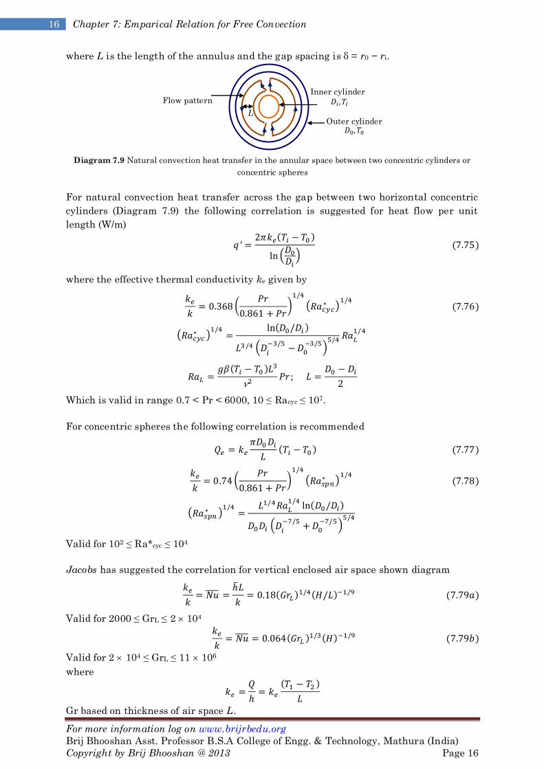
where L is the length of the annulus and the gap spacing is δ = r0 − ri.
Diagram 7.9 Natural convection heat transfer in the annular space between two concentric cylinders or
concentric spheres
For natural convection heat transfer across the gap between two horizontal concentric
cylinders (Diagram 7.9) the following correlation is suggested for heat flow per unit
length (W/m)
where the effective thermal conductivity ke given by
Which is valid in range 0.7 < Pr < 6000, 10 ≤ Racyc ≤ 107.
For concentric spheres the following correlation is recommended
Valid for 102 ≤ Ra*cyc ≤ 104
Jacobs has suggested the correlation for vertical enclosed air space shown diagram
Valid for 2000 ≤ GrL ≤ 2 104
Valid for 2 104 ≤ GrL ≤ 11 106
where
Gr based on thickness of air space L.
Flow pattern
Outer cylinder
Inner cylinder
L

For more information log on www.brijrbedu.org
Brij Bhooshan Asst. Professor B.S.A College of Engg. & Technology, Mathura (India)
Copyright by Brij Bhooshan @ 2013 Page 17
17 Heat and Mass Transfer By Brij Bhooshan
Jacobs has suggested the correlation for horizontal enclosed air space
Valid for 104 ≤ GrL ≤ 4 104
Valid for 4 105 ≤ GrL
where
Globe and Dropkin gives the relation for liquid contained in horizontal space
Valid for 3 x 10⁵ ≤ Gr.Pr ≤ 7 x 10⁹
Radiation R-Value for a Gap
The radiation transfer across a gap separating two large parallel planes may be
calculated with
Using the concept of the R-value
and thus could determine an R-value for the radiation heat transfer in conjunction with
Equation (7.82).
so that
The total R-value for the combined radiation and convection across the space would be
written as
7.9 ROTATING CYLINDERS, DISKS AND SPHERES
Heat transfer by convection between a rotating body and a surrounding fluid is of
importance in the thermal analysis of flywheels, turbine rotors and other rotating
components of various machines. With heat transfer, a critical velocity is reached when
the circumferential speed of the cylinder surface becomes approximately equal to the
upward natural convection velocity at the side of a heated stationary cylinder. Below the
critical velocity, simple natural convection, characterised by the conventional Grashof
number, [gβ(Tw T)D3]/ν2 controls the rate of heat transfer. At speeds greater than
critical (Rew > 8000 in air) the peripheral-speed Reynolds number D2w/ becomes the
controlling parameter. The combined effects of the Reynolds, Prandtl and Grashof
numbers on the average Nusselt number for a horizontal cylinder rotating in air above

For more information log on www.brijrbedu.org
Brij Bhooshan Asst. Professor B.S.A College of Engg. & Technology, Mathura (India)
Copyright by Brij Bhooshan @ 2013 Page 18
18 Chapter 7: Emparical Relation for Free Convection
the critical velocity as shown in diagram (Diagram 7.10) cab be expressed by empirical
equation.
Diagram 7.10 Horizontal cylinder rotating in air
The boundary layer on a rotating disk is laminar and of uniform thickness at rotational
Reynolds numbers wD2/ below about 106. At higher Reynolds numbers the flow
becomes turbulent near the outer edge, and as Rew is increased, the transition point
moves radially inward. The boundary layer thickens with increasing radius (Diagram
7.11).
Diagram 7.11 Velocity and boundary layer profiles for a disk rotating in an infinite environment
For the laminar regime in air
for wD2/ < 106
In the turbulent flow regime (wD2/ν > 106) of a disk in air, the local value at a radius r is
For a sphere of diameter D rotating in an infinite environment with Pr > 0.7 in laminar
regime (Rew = wD2/ν > 5 104), the average Nusselt number (hcD/k) can be obtained
from
while in the regime 5 104 < Rew < 7 105 the equation is
7.10 COMBINED FORCED AND NATURAL CONVECTION
The relative magnitude of the dimensionless parameter Gr/Re governs the relative
importance of natural convection in relation to forced convection where
which represents the ratio of the buoyancy forces to inertia forces. When this ratio is of
the order of unity, i.e. Gr ≌ Re2, the natural and forced convection are of comparable
magnitude, and hence they should be analysed simultaneously. If
Gr / Re2 >> 1: Natural convection dominates
Transition
g
D

For more information log on www.brijrbedu.org
Brij Bhooshan Asst. Professor B.S.A College of Engg. & Technology, Mathura (India)
Copyright by Brij Bhooshan @ 2013 Page 19
19 Heat and Mass Transfer By Brij Bhooshan
Gr / Re2 ≌ 1: Natural and forced convection are of comparable magnitude
Gr / Re2 << 1: Forced convection dominates
For combined free and forced convection in the laminar flow regime inside a circular
tube. Brown and Gauvin recommend the following correlation for the Nusselt number
where Gz is the Graetz number, defined as
where Grd and Red are based on the tubes inside diameter with ΔT = Tw T difference
between tube wall and fluid bulk temperature.
External flow
Nux for mixed convection on vertical plate is given by
If (Grx/Rex-2) ≤ A
If (Grx/Rex-2) > A
A ≌ 0.6 for Pr < 10; A ≌ 1.0 for Pr = 100
For horizontal plate when (Grx/Rex2.5) ≤ 0.083 the equation for forced convection
Internal flow
For mixed convection in turbulent flow in horizontal tubes