hägglunds spider2
TRANSCRIPT

User manual RE 15330-WA/03.2015
Supersedes: EN723-4 BR 2014English
Hägglunds Spider2Control system
DD00070797
The intention of this manual is to give information about standard Spider II control system that is needed for usage of the system, to answer questions from the customers and to give a good level of information about the functions.Information about specific order related conn-ections and configuration is attached in the system documentation at delivery.In order to find particular information, search for the wanted selection as listed in the table of contents. However, changes in the equipment may occur. We therefore reserve the right to introduce amendments in the manual as we deem necessary without notice or obligations.All viewpoints that can make this manual better and more useful are welcome.
Send your viewpoints to:

Bosch Rexroth Mellansel AB, User manual, Hägglunds Spider2 , RE 15330-WA/03.2015
3/68 Contents
Contents
1 Warning signs 51 Indication and settings 61.1 Description 61.2 Serial number 81.3 Card number 91.4 Ordering code 102 Display and Buttons 122.1 Display information 122.2 Information on normal drive and alarms 142.3 Reset of alarms and warnings 152.4 Front panel buttons 162.5 Error Codes 172.5.4 Bus 192.6 Text settings 193 General function 203.1 Block diagram in- and outputs 203.2 Drive controls 213.3 Speed Command 213.4 Ramp 213.5 Stroker current output 223.6 Digital outputs/inputs 223.7 Speed feedback 233.8 Power limitation 233.9 Monitoring 243.10 Basic 243.11 Shredder 253.12 Friction 253.13 Friction slave 263.14 Synchro 273.15 Pressure control 274 Main board, Jumpers & Terminals 284.1 Main card jumpers and indications 284.2 Power supply 324.3 Fieldbus card 334.3.1 Profibus 334.3.2 Modbus RTU 354.3.3 ControlNet 374.5.4 Ethernet/IP 40

4/68
RE 15330-WA/03.2015, User manual, Hägglunds Spider2, Bosch Rexroth Mellansel AB
4.3.5 ProfiNet 414.3.6 DeviceNet 434.3.7 Modbus TCP 454.3.8 CC-link 474.4 Spider control panel card 494.5 Terminal functions 505 Techical data 565.1 Mechanical 565.2 Supply and output voltage 605.3 Inputs 615.4 Outputs 625.5 Communication 636 Commissioning 646.1 Before commissioning 646.3 At commissioning 656.2 After commissioning 657 Maintenance 667.1 General maintenace 667.2 Recommeded scheduled service 667.3 Available spare parts 66
Warning signs 5/68
Bosch Rexroth Mellansel AB, User manual, Hägglunds Spider2 , RE 15330-WA/03.2015
4.3.5 ProfiNet 414.3.6 DeviceNet 434.3.7 Modbus TCP 454.3.8 CC-link 474.4 Spider control panel card 494.5 Terminal functions 505 Techical data 565.1 Mechanical 565.2 Supply and output voltage 605.3 Inputs 615.4 Outputs 625.5 Communication 636 Commissioning 646.1 Before commissioning 646.3 At commissioning 656.2 After commissioning 657 Maintenance 667.1 General maintenace 667.2 Recommeded scheduled service 667.3 Available spare parts 66
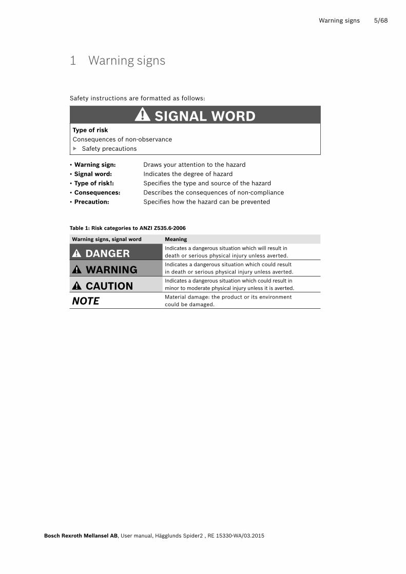
1 Warning signs
Safety instructions are formatted as follows:
SIGnal WorDType of riskConsequences of non-observance
▶ Safety precautions
• Warning sign: Draws your attention to the hazard • Signal word: Indicates the degree of hazard • Type of risk!: Specifies the type and source of the hazard • Consequences: Describes the consequences of non-compliance • Precaution: Specifies how the hazard can be prevented
Table 1: risk categories to anZI Z535.6-2006
Warning signs, signal word Meaning
DanGEr Indicates a dangerous situation which will result in death or serious physical injury unless averted.
WarnInG Indicates a dangerous situation which could resultin death or serious physical injury unless averted.
CaUTIon Indicates a dangerous situation which could result in minor to moderate physical injury unless it is averted.
NOTE Material damage: the product or its environment could be damaged.

6/68 Indication and settings
RE 15330-WA/03.2015, User manual, Hägglunds Spider2, Bosch Rexroth Mellansel AB
1 Indication and settings
1.1 DescriptionThe Spider unit is a microcontroller based system, configurable to suit different application needs. It is designed to match the two or three door PEC or DU power unit also with a one door unit added. The control system can control pumps with double coil or single coil in one direction.
The unit can for PEC be mounted inside the power unit, in the power unit door, on the outside of the power unit or delivered separate with wall brackets or panel flange to be wired in by the customer. Cable sets can be supplied as an option.The unit will for DU be mounted on the power unit side with the control panel on the outside or inside of the front door communicating via CAN. The front panel of the Spider includes a set of buttons for set up, and a set for drive control (one set/drive).The configuration of the pre-programmed system functions is done using the front panel with help from the text displays or via a serial connection from a laptop. The configuration mode can be protected with a password. The system includes a drive monitoring function with drive time counters, alarm/warning list and 8 scalable log channels with data download via serial interface. The Spider unit can control the system with different settings of electricmotor/pump configuration.
DD00070425
Fig. 1: one to four pumps for one drive

Indication and settings 7/68
Bosch Rexroth Mellansel AB, User manual, Hägglunds Spider2 , RE 15330-WA/03.2015
DD00070427
DD00070428DD00070429
Fig. 2: Two to four pumps for two drives with separate function
Fig. 3: Two to four pumps for two drives with common function. If one stops by a fault the other will also.

8/68 Indication and settings
RE 15330-WA/03.2015, User manual, Hägglunds Spider2, Bosch Rexroth Mellansel AB
1.2 Serial number
This serial number system is used up to Serial number -4653.
Serial number after -4653 is Cxxxxx without any correlation to the function. C is standing for Controls but the following number is used for all types of different control equipment.
E01P x x x - xxxx
article group for Spider Serial number
Drive 2 config:
Drive 1 config:
Function:
0= No Emotor, No pump1= 1 Emotor - 1 Pump2= 1 Emotor - 2 Pumps3= 2 Emotors - 2 Pumps4= 2 Emotors - 3 Pumps5= 2 Emotors - 4 Pumps6= 3 Emotors - 3 Pumps7= 3 Emotors - 4 Pumps8= Emotor common w.drive 1 - Tandem pump19= Emotor common w.drive 1 - Tandem pump2
1= 1 Emotor - 1 Pump2= 1 Emotor - 2 Pumps3= 2 Emotors - 2 Pumps4= 2 Emotors - 3 Pumps5= 2 Emotors - 4 Pumps6= 3 Emotors - 3 Pumps7= 3 Emotors - 4 Pumps8= 1Emotor - Tandem pump19= 1Emotor - Tandem pump2
M= Monitor function
B = Basic function
S = Shredder function
Z = Synchro function
F = Friction function
R = MRC function

Indication and settings 9/68
Bosch Rexroth Mellansel AB, User manual, Hägglunds Spider2 , RE 15330-WA/03.2015
1.3 Card numberThe serial card number is marked on the card at final test. The number consists of an serial number and year and week for the production test. The hardware revision marking is adjacent to the card number
Example:
5371 1135 r3B
Serial number Year and week for production test
Hardware revision
Layout Rev A Layout Rev B
DD00070841
10/68 Indication and settings
RE 15330-WA/03.2015, User manual, Hägglunds Spider2, Bosch Rexroth Mellansel AB
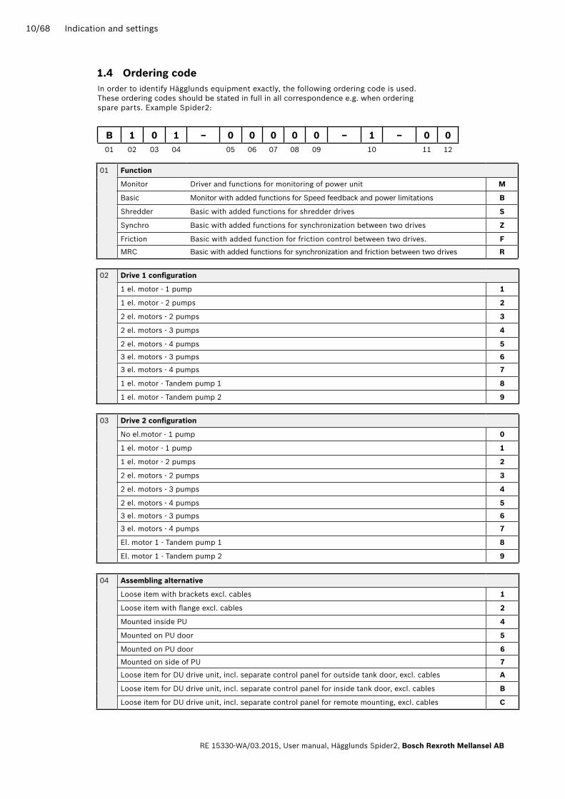
1.4 ordering code
B 1 0 1 – 0 0 0 0 0 – 1 – 0 001 02 03 04 05 06 07 08 09 10 11 12
01 Function
Monitor Driver and functions for monitoring of power unit M
Basic Monitor with added functions for Speed feedback and power limitations B
Shredder Basic with added functions for shredder drives S
Synchro Basic with added functions for synchronization between two drives Z
Friction Basic with added function for friction control between two drives. F
MRC Basic with added functions for synchronization and friction between two drives r
02 Drive 1 configuration
1 el. motor - 1 pump 1
1 el. motor - 2 pumps 2
2 el. motors - 2 pumps 3
2 el. motors - 3 pumps 4
2 el. motors - 4 pumps 5
3 el. motors - 3 pumps 6
3 el. motors - 4 pumps 7
1 el. motor - Tandem pump 1 8
1 el. motor - Tandem pump 2 9
03 Drive 2 configuration
No el.motor - 1 pump 0
1 el. motor - 1 pump 1
1 el. motor - 2 pumps 2
2 el. motors - 2 pumps 3
2 el. motors - 3 pumps 4
2 el. motors - 4 pumps 5
3 el. motors - 3 pumps 6
3 el. motors - 4 pumps 7
El. motor 1 - Tandem pump 1 8
El. motor 1 - Tandem pump 2 9
04 assembling alternative
Loose item with brackets excl. cables 1
Loose item with flange excl. cables 2
Mounted inside PU 4
Mounted on PU door 5
Mounted on PU door 6
Mounted on side of PU 7
Loose item for DU drive unit, incl. separate control panel for outside tank door, excl. cables a
Loose item for DU drive unit, incl. separate control panel for inside tank door, excl. cables B
Loose item for DU drive unit, incl. separate control panel for remote mounting, excl. cables C
In order to identify Hägglunds equipment exactly, the following ordering code is used. These ordering codes should be stated in full in all correspondence e.g. when ordering spare parts. Example Spider2:

Indication and settings 11/68
Bosch Rexroth Mellansel AB, User manual, Hägglunds Spider2 , RE 15330-WA/03.2015
06 Heater
None 0
Installed in Spider box 1
10 Power supply
External 24 VDC 0
Internal 250 W (standard) 1
11 Potentiometer
None 0
Installed in Spider box 1
12 Plexiglas window
None 0
Assembled 1
08 not used
None 0
09 Pressue control
None 0
Pressure control Drive 1 1
Pressure control Drive 2 2
Pressure control both drives 3
07 Fieldbus card
None 0
Profibus 1
Modbus RTU 2
ControlNet 3
Ethernet 4
Profinet 6
DeviceNet 7
Modbus TCP 8
CC-link 9
05 Display
LCD type (standard) 0
VFD type (required for chinese characters) 1

12/68 Display and Buttons
RE 15330-WA/03.2015, User manual, Hägglunds Spider2, Bosch Rexroth Mellansel AB
2 Display and Buttons
2.1 Display informationSpider can be equipped with keypads and display for one or two drives. A Spider unit for one drive has one set of display and drive buttons. A Spider unit for two drives has two sets. All units have one set of set up buttons (arrows and enter button).From main card rev R3A it is possible to place the displays and keypads as a Local interface unit (Spider control panel) separated from the Spider control unit. For a double display unit the positions of Drive 1 and Drive 2 can be switched.
DD00070640
Fig. 4: Front panel
Display 1 Set up buttons
Drive 1 buttons Drive 2 buttons
Display 2

Display and Buttons 13/68
Bosch Rexroth Mellansel AB, User manual, Hägglunds Spider2 , RE 15330-WA/03.2015
DD00070508
Fig. 5: Display text examples

14/68 Display and Buttons
RE 15330-WA/03.2015, User manual, Hägglunds Spider2, Bosch Rexroth Mellansel AB
2.2 Information on normal drive and alarms
Fig. 6: normal drive and alarms
DD00070483
Display and Buttons 15/68
Bosch Rexroth Mellansel AB, User manual, Hägglunds Spider2 , RE 15330-WA/03.2015
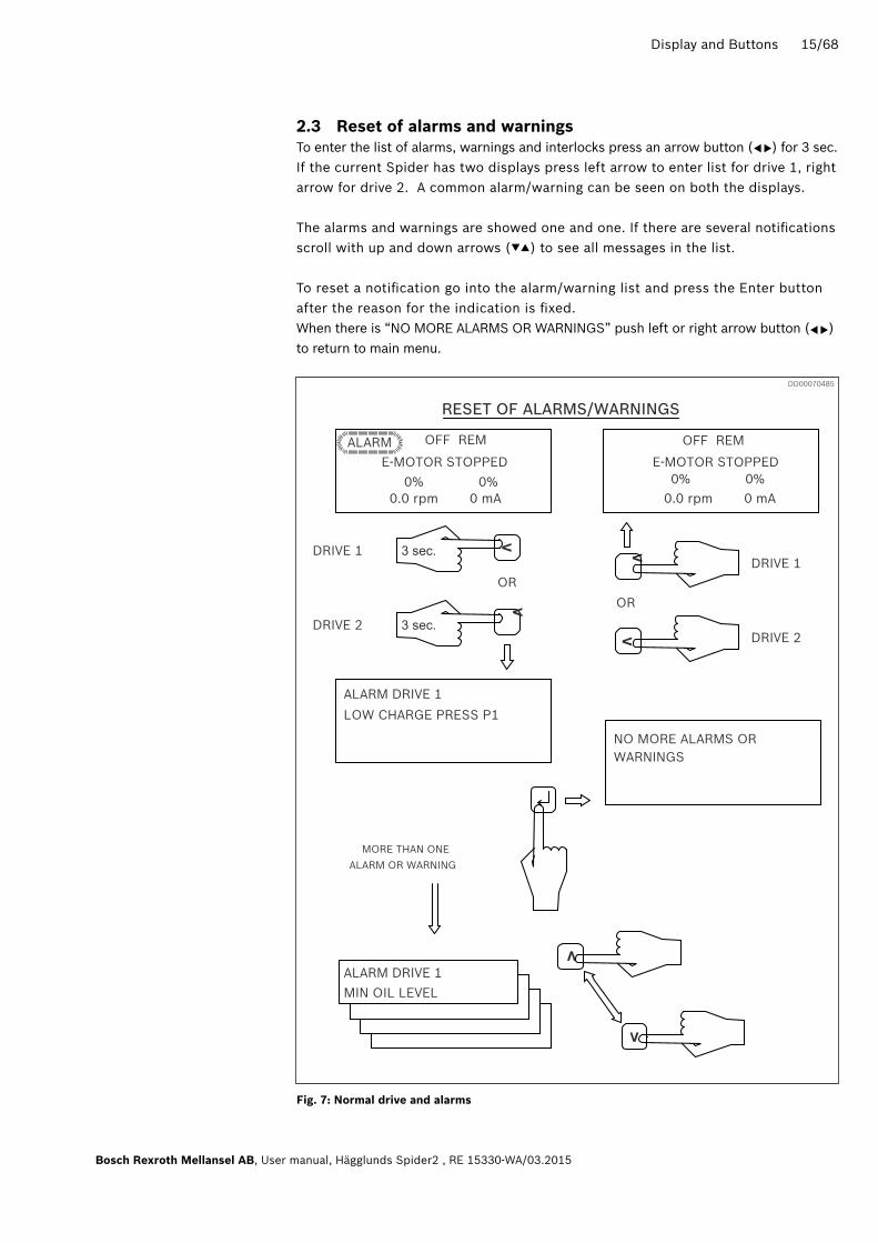
2.3 reset of alarms and warningsTo enter the list of alarms, warnings and interlocks press an arrow button ( ) for 3 sec. If the current Spider has two displays press left arrow to enter list for drive 1, right arrow for drive 2. A common alarm/warning can be seen on both the displays.
The alarms and warnings are showed one and one. If there are several notifications scroll with up and down arrows (▼▲) to see all messages in the list.
To reset a notification go into the alarm/warning list and press the Enter button after the reason for the indication is fixed. When there is “NO MORE ALARMS OR WARNINGS” push left or right arrow button ( ) to return to main menu.
▲
▲
▲
▲
V
V
MIN OIL LEVEL
LOW CHARGE PRESS P1
OFF REM
0% 0% 0.0 rpm 0 mA
E-MOTOR STOPPED
MORE THAN ONEALARM OR WARNING
ALARM DRIVE 1
RESET OF ALARMS/WARNINGS
DRIVE 2
DRIVE 1
ALARME-MOTOR STOPPED
OFF REM
NO MORE ALARMS ORWARNINGS
VV
V
V DRIVE 2
DRIVE 1
0% 0% 0.0 rpm 0 mA
ALARM DRIVE 1
OR
OR
Fig. 7: normal drive and alarms
DD00070485

16/68 Display and Buttons
RE 15330-WA/03.2015, User manual, Hägglunds Spider2, Bosch Rexroth Mellansel AB
2.4 Front panel buttons
2.4.1 Set up buttons
2.4.2 Drive buttons
+++
Go down one level in display menu. Accept a change in parameter. Reset alarm, Warning or interlock.
Go up one level in display menu.Escape without change of parameter.Select Drive 1 scroll list (short time press).Select Drive 1 scroll list (Press for 3 sec).
Select Drive 2 scroll list (short time press).Select Drive 2 scroll list (Press for 3 secs).
Scroll up display menu.Go to next alarm/warning.Increase parameter.
Scroll down display menu.Go to previous alarm/warning.Decrease parameter.
Press 3 sec. to enter setup list.
Increase contrast on display
Decrease contrast on display
Switching between manual and auto drive mode.(Only avaliable in Shredder function)
Switching between front panel and external setpoint/ start-stop if this function is selected.
Increase speed setpoint when driving in local mode (front panel setpoint).
Decrease speed setpoint when driving in local mode (front panel setpoint).
Manual forward in Shredder function.
Switchinge between open and closed loop speed control when speed feedback used. (not available in shredder function).
Inch reverse with fixed speed.Manual reverse in Sheredder function.
Start of drive.
Stop of drive.
Toggling of relay output for DU internal light.
Same button
MAN/AUTO
FORWARD
INCREASE
REVERSE
DECREASE
START
STOP
LOCAL/REMOTE
REG/UNREG
DD00070491
alarm
alarm
available
Switching

Display and Buttons 17/68
Bosch Rexroth Mellansel AB, User manual, Hägglunds Spider2 , RE 15330-WA/03.2015
2.5 Error Codes
2.5.1 Program start
WarnInG EEProM rEaDInG FaIlEDThis error message indicates that the Spider software can‘t read saved parameter values from the memory card. This error can occur if : No memory card connected, memory card defect or wrongly mounted or the information on the memory card is corrupt. Spider software will start with default values on parameters.
WarnInG WronG EEProM VErSIonThis error message indicates that the Spider software can‘t use the parameter values that‘s stored on the memory card because the parameter format stored on the memory card not is compatible with the Spider software used. Spider software will start with default values on parameters.
WarnInG WronG CPlD VErSIonThis error message indicates that the Spider software version used not is compatible with the software version in the CPLD (Complex Programmable Logic Device). The CPLD is used for digital in and outputs, counters, display and Anybus. The Spider will work in an unpredictable way.
WarnInG loG InIT ErrorThis error message indicates that the Spider software can‘t read the real time clock, saved alarms, warnings, drive times or setpoints from the memory card. These functions will not work.This error can occur if no memory card is connected, memory card is defect or wrongly mounted or the information on the memory card is corrupt.The information will also show with a system where the parameters not have been set (first power-on).
WarnInG 3D-loG InIT ErrorThis error message indicates that the Spider software can‘t read the 3D-log on the memory card. The 3D -log function will not function. This error can occur if no memory card is connected, memory card is defect or wrongly mounted or the information on the memory card is corrupt. The information will also show with a system where the parameters not have been set (first power-on).
WarnInG no SErIal nUMBErThis error message indicates that the system serial number not is set with parameter NUM under Log function – Serial number. This number is used in naming of the parameter file from SpiderCom.
WarnInG non CoMPaTIBlE MEM-CThis error message indicates that the system can’t read the memory card. The memory card is not connected, is of wrong type or is faulty.
WarnInG CoMMUnICaTIon To lICThis error message indicates that the system can’t communicate with the Spider control panel card.

18/68 Display and Buttons
RE 15330-WA/03.2015, User manual, Hägglunds Spider2, Bosch Rexroth Mellansel AB
2.5.2 Hardware monitoring
HW Error, FC 1This test is to verify that the delay for electric motor interlock set in hardware with SW1 matches thedelay set in the Spider parameters (for electric motor interlock). If emergency stop is actuated the relays in the hardware will open after set time 2-32 sec. (in 2 sec. steps). If this test not performes within thebelow shown limits, the error message ”HW ERROR, FC 1” will be displayed.The test is performed upon system start up.
HW delay < SW delay software stops
HW delay > SW delay + 4 s Only warning, press a button for OK
HW delay > SW delay + 5 Software stops
When the software stops both Hardware(M) time and Software(S) time is displayed in 1/10 sec so that the times can be verified/corrected.
HW Error, FC 2This test is to verify that the relay that feeds the PWM-outputs opens. If emergency stop is actuatedthe Spider hardware for emergency stop open this relay. This test is performed when all e-motors arestopped. If the relay doesn‘t open on this test, error message ”HW ERROR, FC 2” is displayed andthe software stops.
HW Error, FC 3This test is to verify that the electric motor interlock relays opens. When electric motor interlock isOK the relay is closed and open when interlock not is OK. If the relay not opens, error message ”HW ERROR, FC 3” is displayed and the software stops. This test is performed at power on and once when all electric motors are stopped.
HW Error, FC 4Watchdog indication should not be achieved during normal program execution. If it happens during normal program execution, error message ”HW ERROR, FC 4” is displayed and the software stops. This test is performed continuosly.
HW Error, FC 5If measured current is 50% greater than max configured current a shortcircuit is assumed, error message ”HW ERROR, FC 5” is displayed and the software stops. This test is performed continuosly.

Display and Buttons 19/68
Bosch Rexroth Mellansel AB, User manual, Hägglunds Spider2 , RE 15330-WA/03.2015
2.5.3 Software monitoring
WaTCHDoG TIMEoUTIf the software halts or executes incorrect in that way that the control loop or the user interface loopcan‘t execute within set time limits, error message ”WATCHDOG TIMEOUT” is displayed and the software stops. Program address where the execution stopped is also displayed.
oUTPUT Error PxIf the measured pump current deviates more then the setting in parameter PMx13 from the procentual value of the set current between min and max current (Pox01-04) the output will be cut off. Function can be bypassed with parameter PMx12 set off.
2.5.4 Bus
BUS FaIlAnybus function is selected but the communication does not function. This error is likely to occur if the bus cable not is connected.
BUS HW FaIlAnybus function is selected but the hardware is not functioning. This error is likely to occur if the bus module is missing or defect.
2.6 Text settingsIndicating texts in Aux functions, AMx04 can be set via front panel or SpiderCom.Serial number in drive log must be set via front panel.The text characters are scrolled with ▲ or ▼ buttons and selected with Enter button at the front panel. If the button tapped the characters will change one character at the time. If it is pressed during scroll the character will stopped at fixed positions.
01..89: ; < = > ? @ AB..YZ[ ¥ ] ^ _ ´ a b . . y z { | } → ← Ä v Å Ö ß ü ♪ °C ° F ▼►◄▲ b l a n k ! ” # $ % & ’ ( ) * + , - . /
01..89: ; < = > ? @ AB..YZ[ ¥ ] ^ _ ´ a b . . y z { | } → ← Ä v Å Ö ß ü ♪ °C ° F ▼►◄▲ b l a n k ! ” # $ % & ’ ( ) * + , - . /
Character sequenceVFD:
LCD:
▼
▼
▼
▼
▼
▼
▼
▼
▼
▼
▼
▼
▼▼
▼▼
(stop points with pressed button are 0, a and a, scroll direction: )
(stop points with pressed button are 0, a and a, scroll direction: )
(stop points with pressed button are 9, Z and z, scroll direction: )
(stop points with pressed button are 9, Z and z, scroll direction: )
Japanese and special characters
..To beginning
..To beginning
To end..
To end..

20/68 General function
RE 15330-WA/03.2015, User manual, Hägglunds Spider2, Bosch Rexroth Mellansel AB
El.m. interlock
El.m. started
Str
oker
cur
rent
(s)
El.m. current signal(s)
Sp
eed
enc
oder
sig
nal(
s)
Function:BasicFrictionSyncroShredderPressure
Mon
itor
sw
itch
es
Ana
log
ind
icat
ors
Setpoint(s)
Drive control
Digital/analogindications
3 General function
3.1 Block diagram in- and outputs
DD00070506

General function 21/68
Bosch Rexroth Mellansel AB, User manual, Hägglunds Spider2 , RE 15330-WA/03.2015
3.2 Drive controlsThe drive control buttons on the front panel are for start and stop of the drive, local/remote, speed set point by increase and decrease in local mode, inch reverse, regulated/non-regulated drive and auto/manual drive in shredder mode. These push-button functions can be bypassed in the configuration of the system functions. All above-mentioned functions can also be activated by remote signals (in addition to a lot of other signals that can be activated remotely).
3.3 Speed CommandThe speed set point command can be the local command or a remote command signal.The local command is set with the increase and decrease buttons on the front (or externally via digital inputs for increase/decrease). Remote set point command is a voltage or current signal connected to the terminals (the type is set with a parameter and with jumper SP D1(2).) Remote set point can also be set via fieldbus (optional).The speed command can be locked to local or remote control or be switchable with the local/remote button (or via digital input).At local/remote switching the local set point command can either remain or automatically (or by a digital input) be set to zero (depends on the parameter settings). Local increase/decrease will not affect the local set point when running in remote mode.
3.4 rampThe start ramp time is the time it takes for the signal to control the hydraulic pump, to go from zero to 100% if the speed set point is 100% and drive start is activated.The stop ramp is the time it takes to go from 100% to zero when drive stop is activated.Drive start and stop are ramped commands (as well as fixed forward, fixed reverse and inch reverse). The start ramp is controlled by separate parameters in forward direction and reverse direction. The stop ramp is controlled by separate parameters forward direction and reverse direction.
Example: If the ”up ramp” is set to 10 sec. and the down ramp is set to 5 sec. we will get the following output. The example is based on 50 and 100% set point
DD00070607
Speed
Drive start Drive stop
Stop ramp
Time (sec)
Start ramp
0 10 20 25
100 %
50 %

22/68 General function
RE 15330-WA/03.2015, User manual, Hägglunds Spider2, Bosch Rexroth Mellansel AB
3.5 Stroker current outputThere are two output channels for each pump (one for forward and one for reverse), with individual settings.The outputs are Pulse Width Modulated and the PWM frequency is set in acc. with used stroker. This means the Spider can control pumps with double coil, or single coil in one direction.
Coil resistanceThe system will measure the current in the stroker coil and compensate for the resistance change due to increased temperature.The nominal resistance of used stroker coil is set with a parameter.A typical resistance value is:
HD 41 ΩSP 20 ΩKA (Sauer) 20 Ω
3.6 Digital outputs/inputs
3.6.1 Electric motor interlock outputsThere are 3 normally high off delayed digital outputs for interlock of the electric motors (shall be connected via a relay in the electric motor stop circuit). Each output is high when it is allowed (no alarms) to run corresponding electric motor, and will go low (open) time-delayed after an Alarm. The delay time is set with an individual parameter for each output.
The normal stop sequence at alarm:1. The output to the pump is set to zero without ramp. 2. After a time delay (adjustable) the electric motor interlock is opened.
The output relays are monitored to detect faulty relay contacts. At system power-up and when all e-motors are stopped, the relays will be tested if the emergency stop input not is open. To avoid faulty alarms from the relays, they will be switched on and off 5 times to remove oxidation from the contacts before the test.
3.6.2 Digital outputsThere are 13 digital outputs that can be used to monitor the status of Alarm, Warning or Interlock, or of a digital input.
3.6.3 Functions for monitoringThe monitoring function is available in all setups. There are 43 digital inputs in total. The pre-programmed functions can be used for drive control and monitoring function with 4 different types of indication: Warning = indication on the display (and by a digital output if this function is set).Alarm = indication on the display (and by a digital output if this function is set).

General function 23/68
Bosch Rexroth Mellansel AB, User manual, Hägglunds Spider2 , RE 15330-WA/03.2015
This function will stop the drive without ramp and after a short delay open the electric motor interlock output to stop the motor (see „Electric motor interlock outputs“ above).Interlock = same as alarm but without stopping the electric motor.Disable = same as alarm but without indication in the drive log.
The Warning, Alarm and Interlock indications must be reset in the Alarm/Warning list after the reason for the indication is fixed (see 2.5 Front panel buttons). Disable don’t need to be reset.
3.7 Speed feedback
3.7.1 GeneralSpeed feedback requires a speed encoder, digital or analogue (4-20 mA) and makes it possible to maintain a constant speed at the hydraulic motor shaft. The Spider compensates for speed deviations due to load changes. To achieve this, a PID regulator is implemented in the software. This PID regulator compares the actual speed value with the speed set-point. Any deviation between the two signals is detected as an Error signal and transferred to the PID regulator. The proportional part amplifies the Error signal. The Output is proportional to the Error signal.The Integral stage integrates the Error signal. A small Error signal will over time create a big Integral stage output.Derivative stage derives the Error signal. A rapid change will create a big output from the derivative stage.The results from the three different stages are added to the stroker output.
The use of PI only is most common.A system set up with speed feedback (regulated drive) can be switched between regulated and unregulated mode, by means of panel button „REG/UNREG“ (or by a remote signal).Note: In case the difference between the set point and the actual speed is bigger than a pre-set value and remains so for >10 sec. the drive will automatically be set to unregulated mode (but it will keep on running), and „ERROR TO LARGE“, will be displayed (a digital output will indicate as well, if set).
3.8 Power limitationPower limitation function is not available in the monitor type spider, basic function or higher is needed. Power limitation requires an analog input signal (voltage or current loop signal) from a current transformer that senses the current of the specific electric motor.
If the current consumption of the electric motor exceeds pre-set limitation value, the output current to the stroker will ramp down (towards zero) until the current consumption of the electric motor decreases below set limitation value which will make the output current to the stroker to ramp up, back to previous value.
24/68 General function
RE 15330-WA/03.2015, User manual, Hägglunds Spider2, Bosch Rexroth Mellansel AB
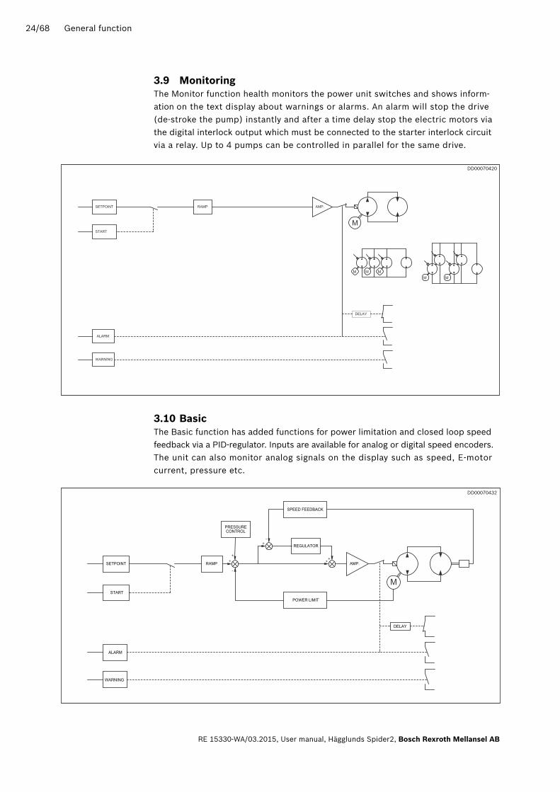
3.9 MonitoringThe Monitor function health monitors the power unit switches and shows inform-ation on the text display about warnings or alarms. An alarm will stop the drive(de-stroke the pump) instantly and after a time delay stop the electric motors via the digital interlock output which must be connected to the starter interlock circuit via a relay. Up to 4 pumps can be controlled in parallel for the same drive.
3.10 BasicThe Basic function has added functions for power limitation and closed loop speed feedback via a PID-regulator. Inputs are available for analog or digital speed encoders. The unit can also monitor analog signals on the display such as speed, E-motor current, pressure etc.
DD00070420
DD00070432

General function 25/68
Bosch Rexroth Mellansel AB, User manual, Hägglunds Spider2 , RE 15330-WA/03.2015
3.11 ShredderThe Shredder function has the same functions as Basic and with added functions for reversing by an overload-stopped drive. It is possible to maximise the number of reversals within a time limit and stop the drive when exceeded. The drive can be set to change direction after an adjustable time interval.
3.12 FrictionThe Friction function has the same functions as Basic and with added functions for control of two hydraulic drives driven together with a ratio between the motors.
DD00070433
DD00070438

26/68 General function
RE 15330-WA/03.2015, User manual, Hägglunds Spider2, Bosch Rexroth Mellansel AB
3.13 Friction slaveThe Friction slave function has the same functions as Basic and with added functions for control of two hydraulic drives driven together with a ratio in relation to the master set point.
DD00070439

General function 27/68
Bosch Rexroth Mellansel AB, User manual, Hägglunds Spider2 , RE 15330-WA/03.2015
3.15 Pressure controlThe pressure control function output is added to the ramped flow command. The func-tion compares actual pressure to a set pressure and gives a positive or negative output depending on sign of the difference and action direction of regulation.
3.14 SynchroThe Synchro function has the same functions as Basic and with added functions for position control between two hydraulic drives. It is possible by an external signal to set the angle between the rolls. Ratio drive is also possible. This mode requires digital speed encoders
DD00070440
DD00070441

28/68 Main boards, Jumpers & Terminals
RE 15330-WA/03.2015, User manual, Hägglunds Spider2, Bosch Rexroth Mellansel AB
4 Main boards, Jumpers & Terminals
4.1 Main card jumpers and indications
4.1.1 revision a
DD00070510
Main boards, Jumpers & Terminals 29/68
Bosch Rexroth Mellansel AB, User manual, Hägglunds Spider2 , RE 15330-WA/03.2015
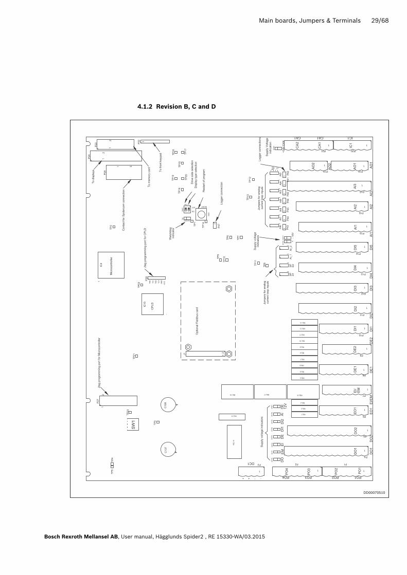
4.1.2 revision B, C and D
DD00070510

30/68 Main boards, Jumpers & Terminals
RE 15330-WA/03.2015, User manual, Hägglunds Spider2, Bosch Rexroth Mellansel AB
4.1.3 Jumpers
Function Jumper name Settings
Signal type for speed setpoint, Drive 1 SP D1Upper position = voltage signal Lower position = current signal
Signal type for speed setpoint, Drive 2 SP D2Upper position = voltage signal Lower position = current signal
Signal type for configurable analog input 1 AI1Upper position = voltage signal Lower position = current signal
Signal type for configurable analog input 2 AI2Upper position = voltage signal Lower position = current signal
Signal type for configurable analog input 3 AI3Upper position = voltage signal Lower position = current signal
Signal type for configurable analog input 4 AI4Upper position = voltage signal Lower position = current signal
Signal type for configurable analog input 5 AI5Upper position = voltage signal Lower position = current signal
Signal type for configurable analog input 6 AI5Upper position = voltage signal Lower position = current signal
Signal type for configurable analog input 7 AI7Upper position = voltage signal Lower position = current signal
Signal type for configurable analog input 8 AI8Upper position = voltage signal Lower position = current signal
Signal type for configurable analog input 9 AI9Upper position = voltage signal Lower position = current signal
Switch level selector for pulse 1 on Speed encoder 1
P48D = Differential pulse encoderS = Single pulse encoder
Switch level selector for pulse 2 on Speed encoder 1
P49D = Differential pulse encoderS = Single pulse encoder
Switch level selector for pulse 1 on Speed encoder 2
P50D = Differential pulse encoderS = Single pulse encoder
Switch level selector for pulse 2 on Speed encoder 2
P51D = Differential pulse encoderS = Single pulse encoder

Main boards, Jumpers & Terminals 31/68
Bosch Rexroth Mellansel AB, User manual, Hägglunds Spider2 , RE 15330-WA/03.2015
4.1.4 Indicators
Function Indicator name note
ShutdownD1, red
(W-DOG)Normally off. Will be active by microprocessor watchdog error.
Digital output supplyD170, green
(DO)
Normally on. Indicates supply to digital outputs. Will be off by external short circuit or by emergency stop.
Emergency stop supplyD171, green
(EM)Normally on. Will be off by external short circuit
E-motor input supplyD172, green
(EI)Normally on. Will be off by external short circuit
Encoder supply 24V D173, green
(DE)Normally on. Will be off by external short circuit
Digital input supply 1D174, green
(DI1)Normally on. Will be off by external short circuit
Digital input supply 2D175, green
(DI2)Normally on. Will be off by external short circuit
Analog input supplyD176, green
(AI)Normally on. Will be off by external short circuit
Encoder supply 12V D181, green
(DE 12V)Normally on. Will be off by external short circuit
+10V ref.voltage for potentiometerD116, green
(+10V)Normally on. Will be off by external short circuit
-10V ref.voltage for potentiometerD117, green
(-10V)Normally on. Will be off by external short circuit
CANbus supply 24V D183, greenNormally on. Will be off by external short circuit
4.1.5 Switches
Function Pos. name note
Emergency stop shutdown SW1Timer for backup emergency stop shutdown
Display type SW3-1On=LCD display type (standard)Off= VFD display type
Drive position on front panel SW3-2On= Drive 1 left (standard)Off= Drive 1 right

32/68 Main boards, Jumpers & Terminals
RE 15330-WA/03.2015, User manual, Hägglunds Spider2, Bosch Rexroth Mellansel AB
4.2.1 Standard versions
4.2 Power supply
24V OK
Main switch
Main fuse
DC connection
Main connection
main fuseSpare
Main fuse
resettable
4AF
Main AC OK
Internal DC fuse 2AF
DD00070442
& D

Main boards, Jumpers & Terminals 33/68
Bosch Rexroth Mellansel AB, User manual, Hägglunds Spider2 , RE 15330-WA/03.2015
4.3 Fieldbus card
DD00070505
Indicator name Description Function Information
D1 Not used Not used Normal function
D2 Online
Green
Off
Module is On-Line and ready, data exchange is possible.
Module is not On-Line.
D3 OfflineRed
Off
Module is Off-Line.
Module is not Off-Line.
D4 Diagnostics
Red flashing 1 Hz
Red flashing 2 Hz
Red flashing 4 Hz
Off
Configuration error. Data length.
Configuration error. User parameter.
Initialisation error of the Profibus
communication ASIC
No error
D5 Watchdog
Green flashing 1Hz
Green flashing 2Hz
Red
Red flashing 1 Hz
Red flashing 2 Hz
Red flashing 4 Hz
Initialized and running OK.
Not initialised.
Unspecified internal error or running in boot loader mode.
RAM failure.
ASIC or FLASH failure.
DPRAM failure.
4.3.1.1 Indicators
4.3.1 Profibus

34/68 Main boards, Jumpers & Terminals
RE 15330-WA/03.2015, User manual, Hägglunds Spider2, Bosch Rexroth Mellansel AB
Indicator name Function Information
S1 Terminating switchOn= Enabled (if first or last in a network)Off= Disabled
S2 Node Adress x1 for the node address setting
S3 Node Adress x10 for the node address setting
Pin Function InformationHousing Shield Connected to PE
1 Not connected
2 Not connected
3 B-line Positive RxD/TxD
4 RTS Request to send*
5 GND Bus Isolated from RS485 side*
6 +5V Bus Isolated from RS485 side*
7 Not connected
8 A-line Negative RxD/TxD
9
*Used for bus terminators in special cases. Normally only A-line, B-line and shield are used.
4.3.1.1 Switches
4.3.1.2 Profibus connector (Female 9-pin D-sub)

Main boards, Jumpers & Terminals 35/68
Bosch Rexroth Mellansel AB, User manual, Hägglunds Spider2 , RE 15330-WA/03.2015
Indicator name Description Function Information
D1 ProcessingGreen flashing
Off
Receiving Query and building response
No Query.
D2 Bus errorRed
Off
Bus error
Normal operation
D3 OfflineRed
Off
Module is Off-Line.
Module is not Off-Line.
D4 HW settings status
Green
Red
Off
Bus ready. Normal operation.
Bus timeout error.
Bus not initialized correctly.
D12 Watchdog
Green flashing 1Hz
Green flashing 2Hz
Red
Red flashing 1 Hz
Red flashing 2 Hz
Red flashing 4 Hz
Initialized and running OK.
Not initialised.
Unspecified internal error or running in boot loader mode.
RAM failure.
ASIC or FLASH failure.
DPRAM failure.
DD00070517
4.3.2.1 Indicators
4.3.2 Modbus rTU

36/68 Main boards, Jumpers & Terminals
RE 15330-WA/03.2015, User manual, Hägglunds Spider2, Bosch Rexroth Mellansel AB
Pin Function InformationHousing Shield Connected to PE
1 Not connected
2 RS232-TX Transmit signal
3 RS232-RX Recive signal
4 Not connected
5 GND Bus Signal grund
6 +5V Bus
7 RS485D0
8 RS485D0
9 Not connected
Indicator name Function Settings Information
S1 Terminating switchOn
Off
Enabled (if first or last in a network)
Disabled
S2:1-7 Node Adress Binary value:12345670000000000000100000100000011
……
1111111
Not valid123……
127
S2:8S3:1-2
Baud rate Binary value
812000001010011100101110111
Not valid1200240048009600
19200 (Default)3840057600
S3:3-4 Parity Binary value
3400
011011
Not validNone(Default)
Even
Odd
S3:5 Physical interface0 = RS-4851 = RS-232
Switch:
Switch:
4.3.2.2 Switches
4.3.2.3 Modbus connector (Female 9-pin D-sub)
Main boards, Jumpers & Terminals 37/68
Bosch Rexroth Mellansel AB, User manual, Hägglunds Spider2 , RE 15330-WA/03.2015
DD00070540
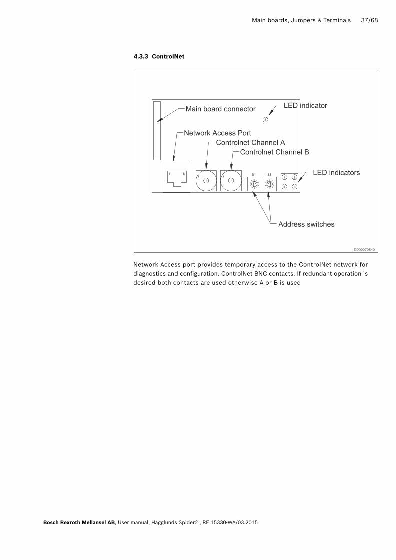
4.3.3 Controlnet
Network Access port provides temporary access to the ControlNet network for diagnostics and configuration. ControlNet BNC contacts. If redundant operation is desired both contacts are used otherwise A or B is used
Indicator name Function Settings Information
S1 Terminating switchOn
Off
Enabled (if first or last in a network)
Disabled
S2:1-7 Node Adress Binary value:12345670000000000000100000100000011
……
1111111
Not valid123……
127
S2:8S3:1-2
Baud rate Binary value
812000001010011100101110111
Not valid1200240048009600
19200 (Default)3840057600
S3:3-4 Parity Binary value
3400
011011
Not validNone(Default)
Even
Odd
S3:5 Physical interface0 = RS-4851 = RS-232
38/68 Main boards, Jumpers & Terminals
RE 15330-WA/03.2015, User manual, Hägglunds Spider2, Bosch Rexroth Mellansel AB
Indicator name Description Function Information
D1 Module status
Green
Green flashing
Red
Red flashing
Connection run state
Connection Idle
Major fault
Minor fault
D2Channel A and channel B
Off
Red
Alternating red/green
Red flashing
Module not initialized
Major fault
Self test
Node configuration error, Mac ID etc
D3Channel A or channel B
Off
Green
Green flashing
Red flashing
Red and green flashing
Channel disabled
Normal operation of channel
Temporary error (node will self correct) or not configured
No other nodes or media fault
Network configuration error
D4 Module ownedOff
Green
No connection has been opened
A connection has been opened tow-ards the module
D5 Watchdog
Green flashing 1Hz
Green flashing 2Hz
Red
Red flashing 1 Hz
Red flashing 2 Hz
Red flashing 4 Hz
Initialized and running OK.
Not initialised.
Unspecified internal error or running in boot loader mode.
RAM failure.
ASIC or FLASH failure.
DPRAM failure.
4.3.3.1 Indicators

Main boards, Jumpers & Terminals 39/68
Bosch Rexroth Mellansel AB, User manual, Hägglunds Spider2 , RE 15330-WA/03.2015
Pin name Function Information
1 ControlNet Tip
2 Shield Ring
Pin name Function Information
1 GND
2 Not connected Transmit signal
3 Tx_H Transmit data, positive
4 Tx_L Transmit data, negative
5 Rx_L Receive data, negative
6 Rx_H Receive data, positive
7 Not connected
8 Shield Connected to PE
Indicator name Function Settings Information
S1 Node adressx10 for the node address setting
Node adress
S2 Node adressx10 for the node address setting
Node adress
4.3.3.2 Switches
4.3.3.3 ControlNet connector (BNC)
4.3.3.4 ControlNet connector (RJ45)
40/68 Main boards, Jumpers & Terminals
RE 15330-WA/03.2015, User manual, Hägglunds Spider2, Bosch Rexroth Mellansel AB
DD00070542
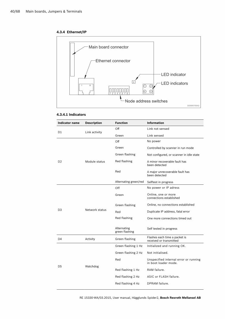
4.3.4 Ethernet/IP
Indicator name Description Function Information
D1 Link activityOff
Green
Link not sensed
Link sensed
D2 Module status
Off
Green
Green flashing
Red flashing
Red
Alternating green/red
No power
Controlled by scanner in run mode
Not configured, or scanner in idle state
A minor recoverable fault has been detected
A major unrecoverable fault hasbeen detected
Selftest in progress
D3 Network status
Off
Green
Green flashing
Red
Red flashing
Alternating green flashing
No power or IP adress
Online, one or more connections established
Online, no connections established
Duplicate IP address, fatal error
One more connections timed out
Self tested in progress
D4 Activity Green flashing Flashes each time a packet is received or transmitted
D5 Watchdog
Green flashing 1 Hz
Green flashing 2 Hz
Red
Red flashing 1 Hz
Red flashing 2 Hz
Red flashing 4 Hz
Initialized and running OK.
Not initialised.
Unspecified internal error or running in boot loader mode.
RAM failure.
ASIC or FLASH failure.
DPRAM failure.
4.3.4.1 Indicators

Main boards, Jumpers & Terminals 41/68
Bosch Rexroth Mellansel AB, User manual, Hägglunds Spider2 , RE 15330-WA/03.2015
4.3.4.2 Switches
Switch name Function Settings
Node adress IP adress: 192.168.0.x(x=Binary value)
Gateway: 255.255.255.0Subnet: 255.255.255.0DHCP: OFF
Binary value:0000001 - 192.168.0.10000011 - 192.168.0.3...
1111111 - 192.168.0.255
4.3.4.3 Ethernet connector (RJ45)
Pin name Function Information
1 TD+
2 TD-
3 RD+
4 Termination
5 Termination
6 RD-
7 Termination
8 Termination
DD00070546
4.3.5 ProfiNet

42/68 Main boards, Jumpers & Terminals
RE 15330-WA/03.2015, User manual, Hägglunds Spider2, Bosch Rexroth Mellansel AB
Indicator name Description Function Information
D1 Link activity
Off
Green flashing
Green
No link
Receiving/Transmitting data
Link established
D2 Communication satus
Off
Green
Green 1 flash
Off line
Connection established and controller in RUN state
Connection established and controller in stop state
D3 Module status
Off
Green
Green 1 flash
Green 2 flashes
Red 1 flash
Red 3 flashes
Red 4 flashes
No power or not initialized
Initialized, no error
Diagnostic data available
Blink. Used by engineeringtool to identify module
Configuration error• Too many modules• I/O size derived from controller
too large• Configuration mismatch
No station address or IP address assigned
Internal error
D4 Not used
D5 Watchdog
Green flashing 1Hz
Green flashing 2Hz
Red
Red flashing 1 Hz
Red flashing 2 Hz
Red flashing 4 Hz
Initialized and running OK.
Not initialised.
Unspecified internal error or running in boot loader mode.
RAM failure.
ASIC or FLASH failure.
DPRAM failure.
4.3.5.1 Indicators
4.3.5.2 ProfiNet connector (RJ45)
Pin name Function Information
1 TD+
2 TD-
3 RD+
4 Termination
5 Termination
6 RD-
7 Termination
8 Termination

Main boards, Jumpers & Terminals 43/68
Bosch Rexroth Mellansel AB, User manual, Hägglunds Spider2 , RE 15330-WA/03.2015
DD00070553
4.3.6 Devicenet
Indicator name Description Function Information
D1 Not used
D2 Network status
Off
Green
Green flashing
Red steady
Red flashing
Not powered/Not online
Link OK, Online, Connected
On line, Not connected
Critical link failure
Connection timeout
D3 Module status
Off
Green
Green flashing
Red steady
Red flashing
No power to device
Device operational
Data size bigger than configured
Unrecoverable fault
Minor fault
D4 Not used
D5 Watchdog
Green flashing 1Hz
Green flashing 2Hz
Red
Red flashing 1 Hz
Red flashing 2 Hz
Red flashing 4 Hz
Initialized and running OK.
Not initialised.
Unspecified internal error or running in boot loader mode.
RAM failure.
ASIC or FLASH failure.
DPRAM failure.
4.3.6.1 Indicators
44/68 Main boards, Jumpers & Terminals
RE 15330-WA/03.2015, User manual, Hägglunds Spider2, Bosch Rexroth Mellansel AB
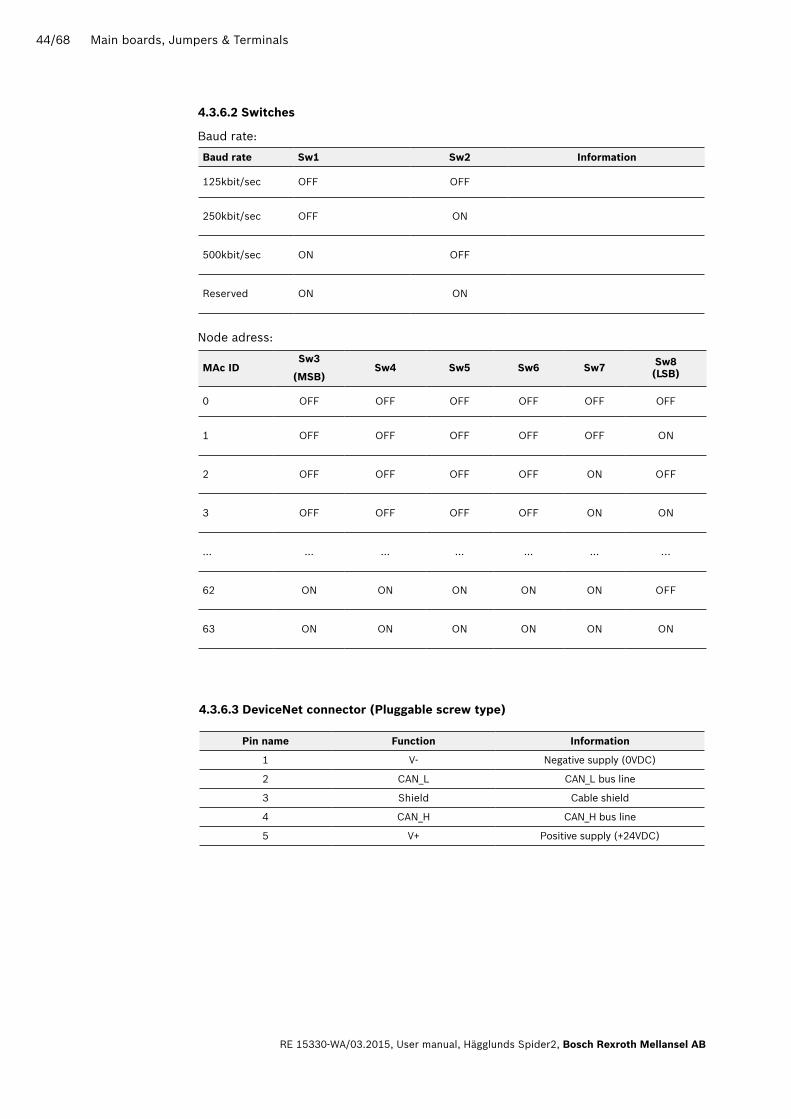
4.3.6.2 Switches
Baud rate Sw1 Sw2 Information
125kbit/sec OFF OFF
250kbit/sec OFF ON
500kbit/sec ON OFF
Reserved ON ON
Mac IDSw3
(MSB)Sw4 Sw5 Sw6 Sw7 Sw8
(LSB)
0 OFF OFF OFF OFF OFF OFF
1 OFF OFF OFF OFF OFF ON
2 OFF OFF OFF OFF ON OFF
3 OFF OFF OFF OFF ON ON
... ... ... ... ... ... ...
62 ON ON ON ON ON OFF
63 ON ON ON ON ON ON
Baud rate:
Node adress:
4.3.6.3 DeviceNet connector (Pluggable screw type)
Pin name Function Information
1 V- Negative supply (0VDC)
2 CAN_L CAN_L bus line
3 Shield Cable shield
4 CAN_H CAN_H bus line
5 V+ Positive supply (+24VDC)

Main boards, Jumpers & Terminals 45/68
Bosch Rexroth Mellansel AB, User manual, Hägglunds Spider2 , RE 15330-WA/03.2015
4.3.7 Modbus TCP
Indicator name Description Function Information
1 Link ActivityOff
Green
Link not sensed
Link sensed
2 Module Status
Off
Green flashing 1Hz
Red flashing 1Hz
Red flashing 2Hz
Red flashing 4Hz
Red
No power
IP address not set using switch
Invalid MAC address
Failed to load config. from FLASH
Internal error (fatal)
Duplicate IP address detected
3Establishedconnections
Established connections to themodule is equal to the number of flashes
4 Activity Green, flashing Flashes eatch time a packet is received or transmitted
5 Watchdog
Green flashing 1Hz
Green flashing 2Hz
Red
Red flashing 1 Hz
Red flashing 2 Hz
Red flashing 4 Hz
Initialized and running OK.
Not initialised.
Unspecified internal error or running in boot loader mode.
RAM failure.
ASIC or FLASH failure.
DPRAM failure.
4.3.7.1 Indicators
DD00070580

46/68 Main boards, Jumpers & Terminals
RE 15330-WA/03.2015, User manual, Hägglunds Spider2, Bosch Rexroth Mellansel AB
4.3.7.2 Switches
Switch name Function Settings
Node adress IP adress: 192.168.0.x(x=Binary value)
Gateway: 255.255.255.0Subnet: 255.255.255.0DHCP: OFF
Binary value:0000001 - 192.168.0.10000011 - 192.168.0.3...
1111111 - 192.168.0.255
4.3.7.3 Modbus TCP connector (RJ45)
Pin name Function Information
1 TD+
2 TD-
3 RD+
4 Normally left unused. Internally tied5 together and terminated to PE.
6 RD-
7 Normally left unused. Internally tied8 together and terminated to PE.

Main boards, Jumpers & Terminals 47/68
Bosch Rexroth Mellansel AB, User manual, Hägglunds Spider2 , RE 15330-WA/03.2015
4.3.8 CC-link
Indicator name Description Function Information
D1 RUN OnOff
Normal operationNo network connection or Timeout
D2 ERRL
RED
OFF
CRC error detectedIllegal station numberillegal baud rate
Normal operation
D3 RDLEDGreen
Off
Data being received
No data transmission
D4 SDLEDGreen
Off
Data being received
No data transmission
D5 Watchdog
Green flashing 1Hz
Green flashing 2Hz
Red
Red flashing 1 Hz
Red flashing 2 Hz
Red flashing 4 Hz
Initialized and running OK.
Not initialised.
Unspecified internal error or running in boot loader mode.
RAM failure.
ASIC or FLASH failure.
DPRAM failure.
4.3.8.1 Indicators
DD00070581

48/68 Main boards, Jumpers & Terminals
RE 15330-WA/03.2015, User manual, Hägglunds Spider2, Bosch Rexroth Mellansel AB
4.3.8.2 Switches
4.3.8.3 CC-link connector (Pluggable screw type)
Pin name Function Information
1 DA Communication line
2 DB Communication line
3 DG Digital ground
4 Shield
5 FG/PE Frame ground
Indicator name Function Information
S1 Baud rate switch
0 = 156k1 = 625k2 = 2,5M3 = 5M4 = 10M9 = FB_INIT
S2 Node adress x1 for the node address settings
S3 Node adress x1 for the node address settings

Main boards, Jumpers & Terminals 49/68
Bosch Rexroth Mellansel AB, User manual, Hägglunds Spider2 , RE 15330-WA/03.2015
4.4 Spider control panel card
DD00070617
The Spider control panel card unit handles the communication between the Spider control unit and the Spider control panel.
Indicator name Description Function Information
D6 Power Green Normal operation, Power OK
D7 Operate Green 2Hz Normal operation
Indicator name Function Information
SW1-1 Drive selection
On = One card is used (Jumpered contact must be connected
in CAN output connector)
Off = Card used for drive 2
Sw1-2 Not used
4.4.1 Indicators
4.4.2 Switches

50/68 Main boards, Jumpers & Terminals
RE 15330-WA/03.2015, User manual, Hägglunds Spider2, Bosch Rexroth Mellansel AB
4.5 Terminal functionsTable of terminal function
row Type name no. Function
1 Power input DC1 4 24V_IN (+)
3 24V_IN (+)
2 GND (–)
1 GND (–)
Pump 4 PO4 4 Common pump 4
3 Stroker connection B
2 Common pump 4
1 Stroker connection A
Pump 3 PO3 4 Common pump 3
3 Stroker connection B
2 Common pump 3
1 Stroker connection A
Pump 2 PO2 4 Common pump 2
3 Stroker connection B
2 Common pump 2
1 Stroker connection A
Pump1 PO1 4 Common pump 1
3 Stroker connection B
2 Common pump 1
1 Stroker connection A
2 Digital outputs DO1 14 Configurable Digital output 6
13 Configurable Digital output 6
12 Configurable Digital output 5
11 Configurable Digital output 5
10 Configurable Digital output 4
9 Configurable Digital output 4
8 Configurable Digital output 3
7 Configurable Digital output 3
6 Configurable Digital output 2
5 Configurable Digital output 2
4 Configurable Digital output 1
3 Configurable Digital output 1
2 24V_DO1 GND

Main boards, Jumpers & Terminals 51/68
Bosch Rexroth Mellansel AB, User manual, Hägglunds Spider2 , RE 15330-WA/03.2015
4 E-motor interlocks EO1 8 Interlock Electric motor 3
7 Interlock Electric motor 3
6 Interlock Electric motor 2
5 Interlock Electric motor 2
4 Interlock Electric motor 1
3 Interlock Electric motor 1
2 24V_DO
1 GND
5 E-motor started inputs E1 8 E-motor 3 started
7 E-motor 2 started
6 E-motor 1 started
5 24V_EI
4 24V_EI
3 GND
EM stop EM 2 Em.stop
1 24V_EM
row Type name no. Function
3 Digital outputs DO2 14 Configurable Digital output 13
13 Configurable Digital output 12
12 Configurable Digital output 11
11 Common Digital output 11-13
10 Configurable Digital output 10
9 Configurable Digital output 10
8 Configurable Digital output 9
7 Configurable Digital output 9
6 Configurable Digital output 8
5 Configurable Digital output 8
4 Configurable Digital output 7
3 Configurable Digital output 7
2 24V_DO1 GND

52/68 Main boards, Jumpers & Terminals
RE 15330-WA/03.2015, User manual, Hägglunds Spider2, Bosch Rexroth Mellansel AB
7 Digital speed DE2 8 Pulse 0 Drive 2+
encover Drive 2 7 Pulse 2 Drive 2 -
6 Pulse 2 Drive 2+
5 Pulse 1 Drive 2 -
4 Pulse 1 Drive 2+
3 12V+
2 24V_DE
1 GND
8 Configurable DI1 8 Config input 6 (Drain filter)
digital inputs 7 Config input 5 (Low oil level in tank)
Predefined 6 Config input 4 (Min oil level in tank)
monitoring 5 Config input 3 (Min oil temperature in tank)
inputs 4 Config input 2 (High oil temperature in tank)
3 Config input 1 (Max oil temperature in tank)
2 24V_DI_1
1 GND
9 Configurable DI2 12 Config input 15digital inputs 11 Config input 14 (Work pressure, pump 2)
Predefined 10 Config input 13 (Charge pressure, pump 2)
monitoring 9 Config input 12 (Suction line, pump 2)
inputs 8 Config input 11 (Return filter 100%, pump 2)
7 Config input 10 (Work pressure, pump 1)
6 Config input 9 (Charge pressure, pump 1)
5 Config input 8 (Suction line, pump 1)
4 Config input 7 (Return filter 100%, pump 1)
3 24V_DI_1
2 24V_DI_1
1 GND
row Type name no. Function
6 Digital speed DE1 8 Pulse 0 Drive 1+
encover Drive 1 7 Pulse 2 Drive 1 -
6 Pulse 2 Drive 1+
5 Pulse 1 Drive 1 -
4 Pulse 1 Drive 1+
3 12V+
2 24V_DE
1 GND

Main boards, Jumpers & Terminals 53/68
Bosch Rexroth Mellansel AB, User manual, Hägglunds Spider2 , RE 15330-WA/03.2015
row Type name no. Function
10 Configurable DI3 12 Config input 24digital inputs 11 Config input 23 (Work pressure, pump 4)
Predefined 10 Config input 22 (Charge pressure, pump 4)
monitoring 9 Config input 21 (Suction line, pump 4)
inputs 8 Config input 20 (Return filter 100%, pump 4)
7 Config input 19 (Work pressure, pump 3)
6 Config input 18 (Charge pressure, pump 3)
5 Config input 17 (Suction line, pump 3)
4 Config input 16 (Return filter 100%, pump 3)
3 24V_DI_1
2 24V_DI_1
1 GND
11 Configurable DI4 12 Config input 33
digital inputs 11 Config input 32
10 Config input 31
9 Config input 30
8 Config input 29
7 Config input 28
6 Config input 27
5 Config input 26
4 Config input 25
3 24V_DI_2
2 24V_DI_2
1 GND
12 Configurable DI5 12 Config input 43
digital inputs 11 Config input 42
10 Config input 41
9 Config input 40
8 Config input 39
7 Config input 38
6 Config input 37
5 Config input 36
4 Config input 35
3 Config input 34
2 24V_DI_2
1 GND
54/68 Main boards, Jumpers & Terminals
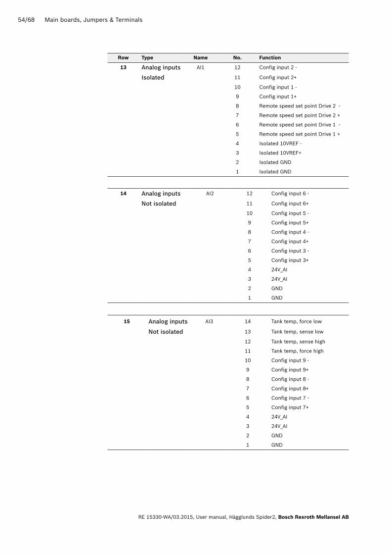
RE 15330-WA/03.2015, User manual, Hägglunds Spider2, Bosch Rexroth Mellansel AB
14 Analog inputs AI2 12 Config input 6 -
Not isolated 11 Config input 6+
10 Config input 5 -
9 Config input 5+
8 Config input 4 -
7 Config input 4+
6 Config input 3 -
5 Config input 3+
4 24V_AI
3 24V_AI
2 GND
1 GND
15 Analog inputs AI3 14 Tank temp, force low
Not isolated 13 Tank temp, sense low
12 Tank temp, sense high
11 Tank temp, force high
10 Config input 9 -
9 Config input 9+
8 Config input 8 -
7 Config input 8+
6 Config input 7 -
5 Config input 7+
4 24V_AI
3 24V_AI
2 GND
1 GND
row Type name no. Function
13 Analog inputs AI1 12 Config input 2 -
Isolated 11 Config input 2+
10 Config input 1 -
9 Config input 1+
8 Remote speed set point Drive 2 -
7 Remote speed set point Drive 2 +
6 Remote speed set point Drive 1 -
5 Remote speed set point Drive 1 +
4 Isolated 10VREF -
3 Isolated 10VREF+
2 Isolated GND
1 Isolated GND

Main boards, Jumpers & Terminals 55/68
Bosch Rexroth Mellansel AB, User manual, Hägglunds Spider2 , RE 15330-WA/03.2015
row Type name no. Function
16 Analog outputs AO2 6 Current output 4
5 Voltage output 4
4 Current output 3
3 Voltage output 3
2 24VDC external supply. Internally supplied from revB
1 GND (external)
AO1 6 Current output 2
5 Voltage output 2
4 Current output 1
3 Voltage output 1
2 24VDC external supply. Internally supplied from revB
1 GND (external)
17 CAN1 CA 8 +24V CAN7 CAN2 L6 CAN2 H
5 0V
CAN2 4 +24V CAN
3 CAN1 L
2 CAN1 H
1 0V
IC 6 For interconnection purpose
5 For interconnection purpose
4 For interconnection purpose
3 For interconnection purpose
2 For interconnection purpose
1 For interconnection purpose

56/68 Techical data
RE 15330-WA/03.2015, User manual, Hägglunds Spider2, Bosch Rexroth Mellansel AB
5 Techical data
Cubicle dimension W=400mm H=300mm D=145mm
Encapsulation class IP 65
Ambient temperature -20...+50 °C, -40 °C with heater *
Material enclosure Stainless steel
Material front Polyester film
Mounting Wall brackets or flange
Weight 8kg (10kg with brackets or flange)
Cable size Max 2.5mm2
* Heater supplied as option
5.1 Mechanical
5.1.1 Mechanical data
5.1.2 Wall bracket mounting
DD00070693

Techical data 57/68
Bosch Rexroth Mellansel AB, User manual, Hägglunds Spider2 , RE 15330-WA/03.2015
5.1.3 Flange mounting
5.1.4 Polyester front
Chemical resistance to:• Alcohols• Dilute acids• Dilute alkalis• Esters• Hydrocarbons• Ketones• Household cleaning agents
DD00070694
58/68 Techical data
RE 15330-WA/03.2015, User manual, Hägglunds Spider2, Bosch Rexroth Mellansel AB
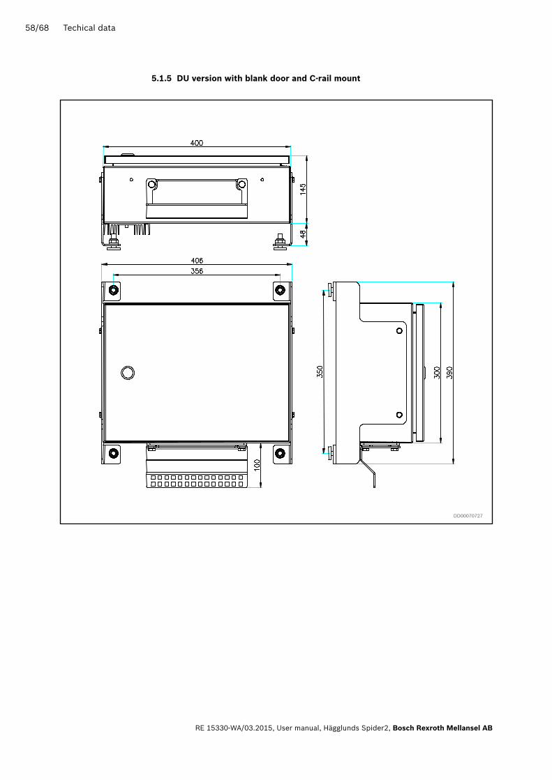
5.1.5 DU version with blank door and C-rail mount
DD00070727

Techical data 59/68
Bosch Rexroth Mellansel AB, User manual, Hägglunds Spider2 , RE 15330-WA/03.2015
5.1.6 Spider control panel
Alternativ e cont act pos ition
PLEXIGLAS S OPTION
WALLMO UNT OPTION
DD00070729

60/68 Techical data
RE 15330-WA/03.2015, User manual, Hägglunds Spider2, Bosch Rexroth Mellansel AB
5.1.7 Supply voltage
5.2.1 output voltage
5.2 Supply and output voltage
Embedded aC power supply
External DC power supply power supply
Main supply voltageAutoranging 90-132, 180-264 VAC 47-63Hz (No configuration needed)
Power consumtionMax 300VA, Depending on configuration (+50VA with heater)*
Inrush current Max 30A
Main fuse 6A
Fuses,Rev B supplyMain Internal DCOutput Fuses, New version
4A fast, 5x20mm ceramic, R9130277882A fast, 5x20mm ceramic, R9130278122A fast, 5x20mm ceramic, R913027812
* Heater supplied as option
Card supply24 VDC ± 10% , Max 8ADepending on configuration
Power consumtion (without load) 320mA
Analog reference voltage(isolated)
+10V-10V
+10 VDC 35 mA-10 VDC 35 mA
Digital input supply 1 DI1 +24 VDC 0.3A
Digital input supply 2 DI2 +24 VDC 0.3A
Digital encoder supply DE +24 VDC 0.3A
Digital encoder supply 12_DE +12 VDC 0.1A
Analog input supply AI +24 VDC 0.3A
Emergency stop supply EM +24 VDC 0.3A
Digital output supply DO +24 VDC 0.8A
E-motor started supply EI +24 VDC 0.3A

Techical data 61/68
Bosch Rexroth Mellansel AB, User manual, Hägglunds Spider2 , RE 15330-WA/03.2015
5.3.1 analog inputs
5.3.2 Digital inputs
5.3 Inputs
no Description Type Impedance
1Speed set point Drive 1 or Friction set point Drive 1(isolated)
±0-5 VDC±0-10 VDC±4-20 mA±0-20 mA
100k Ω100k Ω250 Ω250 Ω
1Speed set point Drive 2 orFriction set point Drive 2(isolated)
±0-5V DC±0-10 VDC±4-20 mA±0-20 mA
100k Ω100k Ω250 Ω250 Ω
2Configurable analog inputs(isolated)
+0-5 VDC+0-10 VDC+4-20 mA+0-20 mA
100k Ω100k Ω250 Ω250 Ω
7Configurable analog inputs(differential)
+0-5 VDC+0-10 VDC+4-20 mA+0-20 mA
100k Ω100k Ω250 Ω250 Ω
1 Tank temp input, -29...+107 ºC PT100
no Description Type Impedance Max input
1Digital speed feedback Drive 1Differential or single with direction signal
logical 0=0-3,9 VDClogical 1=6,6-32 VDC
4,8k Ω 10nF
f max 10 kHz
1 Zero position input Drive 1logical 0=0-3,9 VDClogical 1=6,6-32 VDC
4,8k Ω 10nF
1Digital speed feedback Drive 2Differential or single with direction signal
logical 0=0-3,9 VDClogical 1=6,6-32 VDC
4,8k Ω 10nF
f max 10 kHz
1 Zero position input Drive 2logical 0=0-3,9 VDClogical 1=6,6-32 VDC
4,8k Ω 10nF
1Electric motor 1 startedfrom starter unit
logical 0=0-3,9 VDClogical 1=6,6-32 VDC
1k Ω
1Electric motor 2 startedfrom starter unit
logical 0=0-3,9 VDClogical 1=6,6-32 VDC
1k Ω
1Electric motor 3 startedfrom starter unit
logical 0=0-3,9 VDClogical 1=6,6-32 VDC
1k Ω
43 Configurable inputslogical 0=0-3,9 VDClogical 1=6,6-32 VDC
3k Ω
1 Machine stop inputlogical 0=0-4,7 VDClogical 1=8,0-32 VDC
800 Ω

62/68 Techical data
RE 15330-WA/03.2015, User manual, Hägglunds Spider2, Bosch Rexroth Mellansel AB
5.4.1 Pump control
5.4.3 analog outputs
5.4.2 Digital outputs
5.4 outputs
no Description Type Impedance Max input
4 Stroker output, dual coilPWM (Pulse width modulated)
5-100 Ω** 2A*
* Total current for all outputs 5A** Max output reduced above 10 Ω to 20/Impedance (A)
no Description Type Max input
4
Configurable analog outputsOutputs are internally power supplied from card revision B
+0-10VDC+2-10VDC+0-20mA+4-20mA
1k Ω1k Ω500 Ω500 Ω
no Description Type Max input
1 Starter interlock E-motor 1 Realy contact 3A, 30VDC, 250VAC
1 Starter interlock E-motor 2 Realy contact 3A, 30VDC, 250VAC
1 Starter interlock E-motor 3 Realy contact 3A, 30VDC, 250VAC
13Configurable outputs(Dout 11,12,13 has a combined maximum load of 3A)
Realy contact 3A, 30VDC, 250VAC
Techical data 63/68
Bosch Rexroth Mellansel AB, User manual, Hägglunds Spider2 , RE 15330-WA/03.2015
5.5 Communication
no Description Type Connection to PC
1RS-232 connection for setup and drive log download
9-pole male D-sub Null modem cable
no Description Type Connection
1CAN connection for local system communication
4-pin Terminal To Spider control panel card
no Description Type Connection
1Connection for fieldbus module (optional module)
ProfibusModbus RTUControlNetEtherNet IPProfiNetDeviceNetModbus TCPCC-link
5.5.1 PC connection
5.5.3 Can connection
5.5.2 Fieldbus connection

64/68 Commissioning
RE 15330-WA/03.2015, User manual, Hägglunds Spider2, Bosch Rexroth Mellansel AB
6 Commissioning
6.1 Before commissioning
6.1.1 General Read and understand this complete manual and all other attached technical documentation.Visually check the unit for signs of damage.Check that the serial number is in accordance with the attached Hägglunds order specific documentation.
6.1.2 Electrical
Before power on:Check that the control system is connected according to the Hägglunds orderspecific documentation. Check for short circuit between ground and terminal pins.
With power on:Check green indicators on the main board.Check the function of electrical components and monitoring system manually.Instruments that cannot be actuated can be checked for correct wiring and if possible operated manually.Check the tank oil level sensor and level indication when filling up the tank.Check the interlock function for the electric motor(s).

Commissioning 65/68
Bosch Rexroth Mellansel AB, User manual, Hägglunds Spider2 , RE 15330-WA/03.2015
6.2 after commissioning
Document any changes done during commissioning by updating documentation.Download and save the parameter file.
Important: Store updated documents and parameter file centrally for future use at problem solving or functional change.
6.3 at commissioning
With system speed regulation set OFF and without external load -Check that the required speed is reached. Fine adjustment of speed is done with pump output parameters Pox01 to POx04.For further instructions about settings, see Spider data sheet (Engineering manual).
NOTicE
▶ If speed feedback is required – Set regulation ON and check speed step response, set regulator parameters for a smooth and stable regulation with external load.
High output current can destroy pump control coil!

66/68 Maintenance
RE 15330-WA/03.2015, User manual, Hägglunds Spider2, Bosch Rexroth Mellansel AB
7 Maintenance
7.1 General maintenace
7.2 recommeded scheduled service
7.3 available spare parts
The Spider control system needs only minor maintenance. It is important to keep the inside and outside of Spider box tidy. Avoid excessive exposure to water, vapour and other materials that can cause short circuit, corrosion or abrasive wear.
Inside the Spider box is mounted a VpCI emitter (Vapor phase Corrosion Inhibitor) to protect against oxidation. The emitter contains a pulverous substance and covers all components with a protective layer when the air inside the enclosure is saturated Life time after installation is two years, expiry date is shown on sticker beside the installed emitter. Item number for the emitter is R978980579 (1241 0001-001).
Main circuit board, power supply and displays are some of the key spare parts ava-ilable in case of a break down. Only trained personnel should perform repairs of the Spider. Contact your reseller for more information of repairs.

Bosch Rexroth Mellansel AB SE-895 80 MellanselSwedenTel. +46 (0) 660 870 00Fax +46 (0) 660 871 [email protected]/hagglunds
We reserve the right to make changesPrinted in SwedenRE 15330-WA/03.2015
Your local contact can be found at: www.boschrexroth.com/adresses