hf ring modulator kit building manual - effectpedalkits.com · effect pedal kits: hf ring modulator...
TRANSCRIPT

HF Ring Modulator Kit Building Manual

Effect Pedal Kits: HF Ring Modulator
This HF Ring Modulator kit is based on the Jen HF Modulator, a cool pedal that was produced in the 70s. Depending on how you set the controls the HF Ring Modulator will be closer to a tremolo or a ring modulator. It is able to produce a huge amount of noises as well as quite psychedelic tones, specially if combined with a fuzz in front of it (we highly recommend the Fuzz Machine!).
The HF Ring Modulator has three knobs that will give you control over the Speed, Intensity and Tone of the sound produced. While it might not be a pedal to use in a regular way, it's a useful pedal to add to your pedalboard when you need to get a different sound or want to experiment with new tones.

BOM (1/2) Resistors (14) Capacitors (12)
2 R1, R3 33k 1 C1 100u (electrolytic)
1 R2 1M 1 C2 3.3n
2 R4, R14 100k 1 C3 10n
1 R5 560k 3 C4, C6, C7 220n
1 R6 12k 1 C5 220p
1 R7 1.2k 1 C8 100n
2 R8, R9 220k 1 C9 2.2n
1 R10 2.2M 3 C10, C11, C12 47n
1 R11 10k
1 R12 18k
1 R13 2.2k

BOM (2/2) Diodes, Transistors and ICs Generic Parts and Potentiometers
3 Q1, Q2, Q3 2N3904 1 Battery clip
1 DC Jack
1 RLED 1k LED resistor
1 LED Bezel
1 3PDT
2 IN, OUT 6.35mm Jacks
1 100k Logarithmic (A) Potentiometer Speed
2 100k Linear (B) Potentiometer Int, Tone

Component Placement
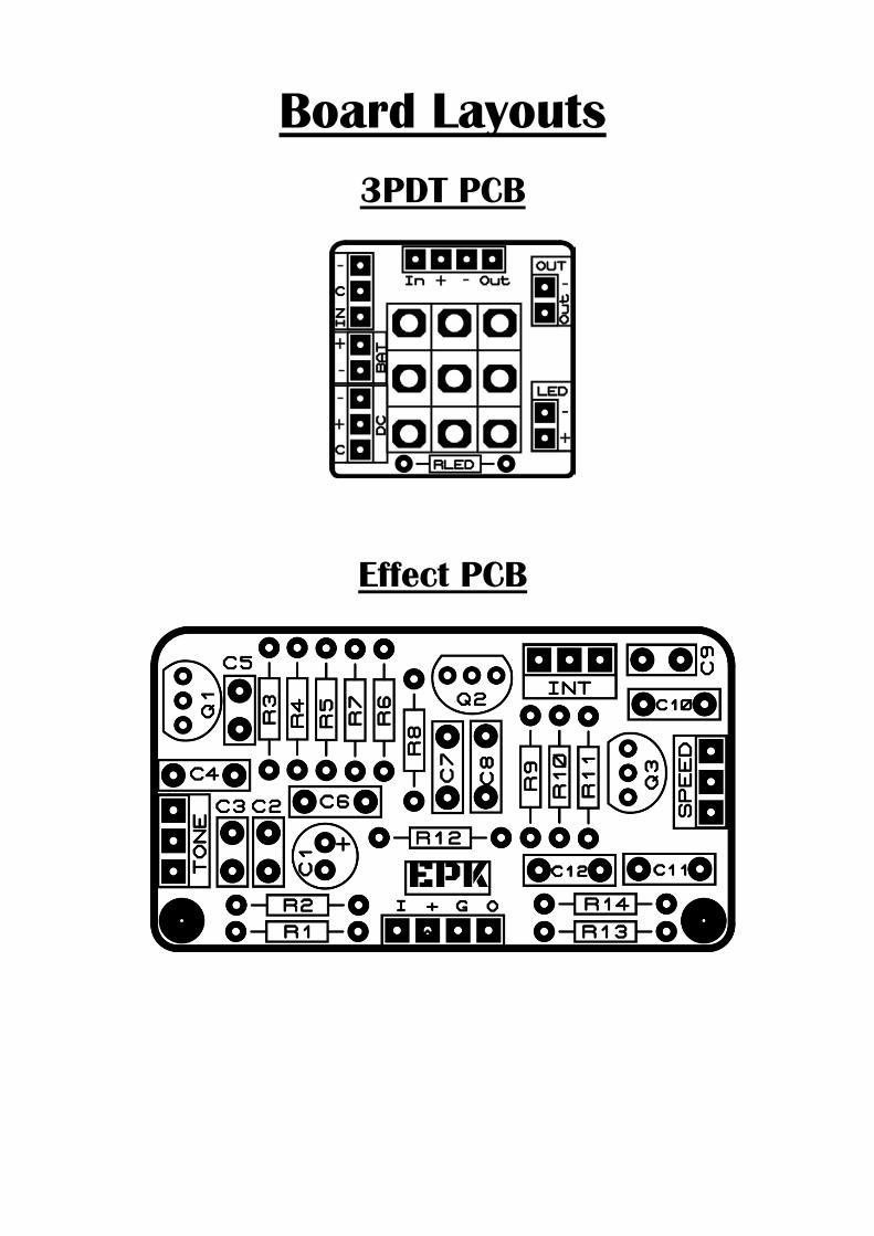
Board Layouts
3PDT PCB
Effect PCB

Building Tips 1- Pay attention to the orientation of the 3PDT! In the following picture
you can see how the 3PDT pins should be positioned (inserting the pins in the holes can be a bit tight to avoid movement while soldering):
2- For a proper soldering you just have to apply the right amount of solder wire. A right solder joint should have a concave shape around the joint and look like this:
3- Don’t apply too much heat! When soldering, the time you hold the solder iron against the joint should be as short as posible to avoid damaging any part (a few seconds should be enough). If you can’t get a solder joint right, let it cool a bit before trying again.
4- If having troubles with the building, checking the schematic in the last page will help you find where the audio signal stops. When you find the spot, check out that everything around that joint is ok (components placed at their right place, solder joints…).

Building Tips 5- Pay attention to the parts that have a polarity and make sure they are
connected as in the component placement picture:
- ICs (they have a small dot or indication that must fit the indication in the board
- Electrolytic capacitors (longer pin is connected to the “+” hole):
- Diodes (check for the mark and make it fit with the one in the PCB):
- Leds (longer pin is connected to the “+” hole)
- Transistors (inserted to fit the drawing in the PCB)

Building Tips 6- With the kit we include plastic PCB supports with an adhesive bottom. You
can use them to anchor the PCB to your enclosure for a better stability. Just insert the PCB support tip into the 3.5mm holes and remove the adhesive protective film.
To avoid any issue always check the latest building manual. Use the pictures only as a reference! Colors/shapes of wires, PCB or parts can change slightly,
this doesn’t affect their functionality in any way.
Always double check part polarity, resistor and capacitor values, potentiometer placement, IC orientation… before soldering.

Schematic