hersey hbmag electromagnetic flow meters - mueller...
TRANSCRIPT

HbM
AG
06/2014
Hersey HbMAG Electromagnetic Flow Meters
Battery OperatedElectromagneticWater Meter
Operating Instructions
Introduction1
Connecting5
Troubleshooting/FAQs8
Safety Notes2
Technical Data9
Description3
Operation6
AppendixA
Installing/Mounting4
Service and Maintenance7
Danger indicates that death or severe personal injury will result if proper precautions are not taken
Warning indicates that death or severe personal injury may result if proper precautions are not taken.
Caution with a safety alert symbol, indicates that minor personal injury can result if proper precautions are not taken.
Caution without a safety alert symbol, indicates that property damage can result if proper precautions are not taken.
Notice indicates that an unintended result or situation can occur if the relevant information is not taken into account.
WarningMueller Systems products may only be used for the applications described in the catalog and in the relevant technical documentation. If products and components from other manufacturers are used, these must be recommended or approved by Mueller Systems. Proper transport, storage, installation, assembly, commissioning, operation and maintenance are required to ensure that the products operate safely and without any problems. The permissible ambient conditions must be complied with. The information in the relevant documentation must be observed.
Legal Information Warning Notice SystemThis manual contains notices you have to observe in order to ensure your personal safety, as well as to prevent damage to property. The notices referring to your personal safety are highlighted in the manual by a safety alert symbol, notices referring only to property damage have no safety alert symbol. These notices shown below are graded according to the degree of danger.
If more than one degree of danger is present, the warning notice representing the highest degree of danger will be used. A notice warning of injury to persons with a safety alert symbol may also include a warning relating to property damage.
Qualified PersonnelThe product/system described in this documentation may be operated only by personnel qualified for the specific task in accordance with the relevant documentation, in particular its warning notices and safety instructions. Qualified personnel are those who, based on their training and experience, are capable of identifying risks and avoiding potential hazards when working with these products/systems.shown below are graded according to the degree of danger.
Proper use of Mueller Systems productsNote the following:
TrademarksAll names identified by ® are registered trademarks of Mueller Systems. The remaining trademarks in this publication may be trademarks whose use by third parties for their own purposes could violate the rights of the owner.
Disclaimer of LiabilityWe have reviewed the contents of this publication to ensure consistency with the hardware and software described. Since variance cannot be precluded entirely, we cannot guarantee full consistency. However, the information in this publication is reviewed regularly and any necessary corrections are included in subsequent editions.
Hersey HbMAGElectromagnetic Flow Meters

Table of contents
1 Introduction 1 1.1 Items supplied 1
1.2 History 1
1.3 Further Information 1
2 Safety Notes 2 2.1 General safety instructions 2
2.2 Laws and directives 2
2.3 Lithium batteries 2
2.4 Installation in hazardous area 3
3 Description 3 3.1 System components 3
3.2 Operating principle 3
3.3 Design 3
3.4 Benefits 3
4 Installing/Mounting 3 4.1 Introduction 3
4.2 Sensor installation 4
4.2.1 Locating the sensor 4
4.2.2 Orienting the sensor 5
4.2.3 Mounting the sensor 5
4.3 Potential equalization 7
4.4 Grounding 7
4.5 Cathodic-protected pipes 8
4.6 Potting and direct burial 8
4.7 Transmitter installation 9
5 Connecting 9 5.1 General safety requirements 10
5.2 Remote version 10
5.3 Power supply 10
5.4 Outputs 12
5.5 Communication modules 12
5.6 Connection of add-on modules 13
HbM
AG
Hersey HbMAG

Table of contents
6 Operation 13 6.1 Meter operation via key and display 13
6.2 Display symbols 14
6.3 Default display information and accessible display menus 14
6.4 Operator menu 15
6.5 Data protection 17
6.6 Internal data handling 18
6.7 Battery-powered operation 18
7 Service and Maintenance 20 7.1 Maintenance 20
7.2 Hersey HbMAG service guidelines 20
7.3 Replacing transmitter or PCB board 21
7.4 Batttery replacement 21
7.5 Power up with battery reset, date and time set up 22
7.6 Verification 22
7.7 User sealings 23
7.8 Technical support 23
7.9 Return procedures 23
7.10 Battery disposal 23
8 Troubleshooting/FAQs 23 8.1 Fault codes 23
8.2 Built-in functions 26
8.3 Flow simulation 27
Hersey HbMAGElectromagnetic Flow Meters

HbM
AG
Table of contents
9 Technical data 27 9.1 Hersey HbMAG 27
9.2 Sensor 27
9.3 Transmitter 28
9.4 Power supply 29
9.5 Output characteristics 31
9.6 Meter uncertainty 33
9.7 The effect of temperature Hersey HbMAG 34
9.8 Dimensions and drawings 35
A Appendix 38 A.1 Unit conversion table 38
A.2 Parameter lists 38
A.2.1 1-99 39
A.2.2 100-199 39
A.2.3 200-299 40
A.2.4 300-399 43
A.2.5 400-499 44
A.2.6 500-599 45
A.2.7 600-799 46
A.3 Sizing sensor 51
A.3.1 Sizing table 2" ... 48" 51
A.4 Certificates 51
A.4.1 Certificates 51
A.5 Spare parts/Accessories 51
A.5.1 Ordering 51
A.6 Features 54
Index 55
Hersey HbMAG

These instructions contain all the information you need for using the device.
The instructions are aimed at persons mechanically installing the device, connecting it electronically, configuring the parameters and commissioning it as well as service and maintenance engineers.
Note
It is the responsibility of the customer that the instructions and directions provided in the manual are read, understood and followed by the relevant personnel before installing the device.
1.1 Items Supplied
•HbMAG•Calibrationcertificate•OperatingInstructions•literatureCD
Inspection 1. Check for mechanical damage due to possible improper handling during shipment. All claims for damage are to be made promptly to the shipper.
2. Make sure the scope of delivery, and the information on the type plate corresponds to the ordering information.
Device Identification
1.2 History The contents of these instructions are regularly reviewed and corrections are included in subsequent editions. We welcome all suggestions for improvement.
The following table shows the most important changes in the documentation compared to each previous edition.
1.3 Further Information The contents of these Operating Instructions shall not become part of or modify any prior or existing agreement, commitment or legal relationship. All obligations on the part of Mueller Systems are contained in the respective sales contract which also contains the complete and solely applicable warranty conditions. Any statements contained herein do not create new warranties or modify the existing warranty.
Product information on the Internet The Operating Instructions are available on the CD-ROM shipped with the device, and on the Internet on the Mueller Systems homepage, where further information on the range of Hersey HbMAG may also be found:Product information on the internet (http://www.MuellerSystems.com/)
Contact Information If you need more information or have particular problems not covered sufficiently by the operating instructions, please get in touch with Mueller Systems. You can find additional information for your local contact person at 800-323-8584.
Figure 1-1 HbMAG label
Introduction1
Edition Remarks
1 None
Hersey HbMAGElectromagnetic Flow Meters
1
HbM
AG
Note
It is the responsibility of the customer that the instructions and directions provided in the manual are read, understood and followed by the relevant personnel before installing the device.
2.1 General safety instructions
2.2 Laws and Directives General requirements Installation of the equipment must comply with local, state and national regulations.
Instrument safety standards The device has been tested at the factory, based on the safety requirements. In order to maintain this condition over the expected life of the device the requirements described in these Operating Instructions must be observed.
2.3 Lithium Batteries Lithium batteries are primary power sources with high energy content designed to represent the highest possible degree of safety.
Safety Notes2
CautionCorrect, reliable operation of the product requires proper transport, storage, positioning and assembly as well as careful operation and maintenance. Only qualified personnel should install or operate this instrument.
CautionMaterial compatibility
Mueller Systems can provide assistance with the selection of the proper meter. However, the full responsibility for the selection rests with the customer and Mueller Systems can take no responsibility for any failure due to material incompatibility.
WarningPotential hazard
Lithium batteries may present a potential hazard if they are abused electrically or mechanically. This is in most circumstances associated with the generation of excessive heat where internal pressure may cause the cell to rupture.
Thus the following basic precautions should be observed when handling and using lithium batteries:
• Donotshort-circuit,rechargeorconnectwithfalsepolarity.
• Donotexposetotemperaturebeyondthespecifiedtemperaturerangeorincineratethebattery.
• Donotcrush,punctureoropencellsordisassemblebatterypacks.
• Donotweldorsoldertothebattery’sbody.
• Donotexposecontentstowater.
Hersey HbMAG
2

3.1 System Components An HbMAG flow meter system includes: • Atransmitterandasensor.Thetransmitteriseithercompact mounted (integral) or remote mounted at a distance of 33' max..• Aninternallyorexternallymountedbatterysupplyor115...230V AC or 12/24 V AC/DC power supply with battery backup.
Communication solutionsThe following communication modules are available:• EncoderinterfaceforAMRandAMIsolutions.
3.2 Operating Principle HbMAG is a microprocessor-based water meter with graphical display and key for optimum customer operation and information on site. The transmitter drives the magnetic field in the sensor, evaluates the flow signal from the sensor, and calculates the volume passing through. It delivers the required information via the integrated pulse output or communication interfaces as part of a system solution. Its intelligent functionality, information and diagnostics ensure optimum meter performance and information to optimize water supply and billing.
The Hersey HbMAG is configured to achieve up to 6 years of battery life in typical revenue applications with the integral battery and up to 10 years with the remote battery pack.
3.3 Design HbMAG is a battery-supplied magnetic inductive flow meter for revenue, district and irrigation metering application.
4.1 Introduction Hersey HbMAG flow meters are suitable for indoor and outdoor installations. • Makesurethatpressureandtemperaturespecificationsindicatedon the device type plate/label are not exceeded.
General InformationThis chapter describes how to install the flow meter in the compact version as well as in the remote version.
3.4 Benefits • Simpleplacementofthemeter-installthemeterinametervaultor burryitunderground.TheIP68(NEMA6P)designisunaffectedby meter position or in-line piping stresses, and there is no requirement for filters or strainers.
• Lowpressureloss-anunrestrictedflowtubeensuresminimal pressure loss, even at the highest flow rates. Overall network system pressures can be reduced, helping to prevent leakage from burst pipes and excess stress placed on pumping stations.
• Zeromaintenance-designedwithoutmovingpartsandhasuptoa 10-year battery life.
ª Measurement in both directions - only one meter required for measuring in both directions.
• Intelligentmeter-onlyonemeterforleakdetection,datalogger function, and self-detection of errors.
• CompatiblewithMuellerSystemsAMRandAMIsolutions
2.4 Installation in hazardous area This device is not approved for use in hazardous areas.
Description3
Installing/Mounting4
Figure 3-1 HbMAG compact Figure 3-2 HbMAG remote Figure 4-1 Compact Installation
87L1
30.1
0
Hersey HbMAGElectromagnetic Flow Meters
3

HbM
AG
The installation consists of two steps: 1. Sensor installation.2. Transmitter installation (remote version only).
4.2 Sensor Installation The installation consists of two steps: 1. Locating the sensor.2. Orienting the sensor.3. Mounting the sensor.
4.2.1 Locating The Sensor Ensurethatthesensorislocatedinthemostoptimumplace.
General Information
Ensurethatsensor ismounted incorrectflowdirectionas indicatedonlabel.
If process flow direction is opposite of flow direction indicated on sensor label, forward flow rates can be restored via software parameter FT327, if factor is adjusted to "-1".
Inlet and outlet conditionTo achieve most accurate flow measurement it is essential to have certain straight inlet and outlet pipe lengths as shown (Di: sensor diameter).
Partially filled pipesFor partially filled pipes or pipes with downwards flow and free outlet, sensor must be mounted in a U-tube.
Therefore avoid:• Airinpipe.• Installationatthehighestpointinpipesystem.• Installationinverticalpipeswithfreeoutlet.
Sensor must be completely full of liquid
Figure 4-2 Remote Installation
Hersey HbMAG
4

4.2.3 Introduction 1. Install gaskets.2. Ensureconnectionflangehasasmoothsurfaceandis in linewith sensor.
Gaskets are recommended but not included in flowmeter delivery.
ExampleA flow velocity of 3 m/s (10 ft./sec.) (V) in a sensor with a diameter reduction from 4 Inch to 3 Inch (d1/d2 = 0.8) gives a pressure drop of 0.04 psi.
With an 8° reducer, the following pressure drop curve applies. The curves are applicable to water.
4.2.2 Orienting The Sensor Horizontal Pipes
Sensor must be mounted as shown in upper part of figure. Do not mount sensor as shown in lower part of figure as electrodes then will be positioned at top where air bubbles may occur and in bottom, where mud, sludge, sand etc. may deposit.
If"EmptyPipeDetection"isused,sensorshouldbetilted45°asshownin upper right figure to maximize full pipe detection and provide accurate volume calculations.
Horizontal PipesRecommended installation is in a vertical/inclined pipe to minimize wear and deposits in sensor.
Installation In Large PipesThe water meter can be installed between two reducers (e.g. DIN 28545).
Note
Physical installation of battery pack may influence battery capacity. Optimal battery capacity is achieved with battery pack in an upright position. Installation examples marked with dotted cross will affect battery capacity.
Hersey HbMAGElectromagnetic Flow Meters
5

HbM
AG
TorqueAdvice for gasket selection:• Onlyuseflatrubbergaskets.• Thickness1...6mm(0.0...0.02ft)dependentongap/tolerance.• Innerdiametermustbelargerthanboreofflowmeter.• Materialshouldbecompatiblewithprocessfluid.
Hardness should be maximum 75 Shore A.
Maximum allowable torquesStandard bolts must be well lubricated and tightened evenly around gasket.
Leakage/damage to flow meter or piping may arise if bolts are over tightened.
Torque calculationsAll values are theoretical and are calculated on the assumption that:• AllboltsarenewandmaterialselectionisaccordingtoEN1515-1 table 2.• Gasketmaterialnotexceeding75shoreAisusedbetweentheflow meter and mating flanges.• Allboltsaregalvanizedandadequatelylubricated.• Flangesaremadeofcarbonsteel.• Flowmeterandmatingflangesarecorrectlyaligned.
Nominal size Class 150 AWWA
inch Mm f/lbs Nm f/lbs Nm
3" 80 25 34 N/A N/A
4" 100 19 26 N/A N/A
5" 125 31 42 N/A N/A
6" 150 42 57 N/A N/A
8" 200 65 88 N/A N/A
10" 250 73 99 N/A N/A
12" 300 97 132 N/A N/A
14" 350 166 225 N/A N/A
16" 400 155 210 N/A N/A
18" 450 162 220 N/A N/A
20" 500 148 200 N/A N/A
24" 600 207 280 N/A N/A
28" 700 N/A N/A 148 200
30" 750 N/A N/A 177 240
32" 800 N/A N/A 192 260
36" 900 N/A N/A 177 240
40" 1000 N/A N/A 207 280
42" 1050 N/A N/A 207 280
44" 1100 N/A N/A 214 290
48" 1200 N/A N/A 229 310
Torques
Hersey HbMAG
6

4.3 Potential Equalization Liquid potential equalization or grounding is accomplished with built-in grounding electrodes and/or grounding rings. The electrodes ensure electrical connection between liquid and meter providing a stable and accurate measurement.
4.4 Grounding The sensor body must be grounded using grounding/bonding straps and/or grounding rings to protect flow signal against stray electrical noise and/or lightning. This ensures that noise is carried through sensor body and that the measuring area within sensor body is noise-free.
Metal PipesConnect straps to both flanges with 6 mm (1/4") screws
Bonding/grounding straps are part of delivery and pre-mounted on flow meter.
Plastic pipes and lined metal pipesUse optional grounding rings at both ends.
Grounding rings are not included in delivery.
1 Built/in grounding electrode 2 Grounding rings mounted on HBMAG
1 Metal Pipes 1 Plastic pipes or lined metal pipes
Hersey HbMAGElectromagnetic Flow Meters
7

Combination of metal and plastic pipesUse straps for metal pipe and grounding rings for plastic pipe.
Bonding/grounding straps, grounding rings and straps are not included in delivery.
1 Metal Pipe 2 Plastic Pipe
4.5 Cathodic-protected pipes Pay special attention to meter installation in cathodic-protected pipe.
Isolate meter from pipeline by mounting isolation sleeves and washers on flange bolts and connect a wire dimensioned to manage the cathodic current and environmental influence, between pipelines.
4.6 Potting and direct burial Combination of metal and plastic pipes
MeterisratedIP68/NEMA6Pfromthefactoryasstandard.Ifcableglandsareadded,IP68/NEMA6Penclosureratingisobtainedbypotting transmitter bottom with Sylgard potting kit. Otherwise onlyanIP67/NEMA4ratingisobtained.
Ensuring IP68/NEMA 6P enclosure rating and preventing wateringress:
1. Select the proper gland size to fit installed cable size.
2. Mount O-ring properly and correctly and grease with gel.
3. Fill Sylgard potting kit in bottom part of casing.
4. Renew Silicagel bag to prevent condensation within meter, if necessary
HbM
AG
Note
All straps or grounding wires must be 12 AWG (or heavier) copper wire and connected with 6 mm screws.
Note
Important EnsurenottofillSylgardpottingkitinthe space for the battery pack.
Do not pot meter before electrical connections have been made.
Caution
Hersey HbMAG
8

4.7 Transmitter Installation Mount bracket on a wall as shown below or on a horizontal or a vertical pipe using ordinary hose clips or duct straps.
Wall Mounting
Pipe MountingSuggestions for direct burial of remote sensor
RemotesensorisprotectedtoIP68/NEMA6Pandcanbeburied.
The use of pea gravel, at least 12 inches all around sensor, is recommended to provide some drainage and to prevent dirt from solidifying on sensor.
It also helps to locate the sensor should excavation be necessary. Before covering pea gravel with earth, use electrical cable identification tape above gravel.
Run remote sensor cable through a plastic conduit of minimum 2” or 50 mm.
Figure 4-3 Wall Mounting
Figure 4-4 Pipe mounting - vertical
Figure 4-5 Pipe mounting - horizontal
This chapter consists of general safety requirements as well as a description of how to connect the device.
The connection of the device is done in four steps.1. Wiring sensor and transmitter (remote version only).2. Connecting power supply.3. Connecting outputs.4. Connecting add-on module.
Connect Diagram
3.6 V DC battery connector - male and pulse connection terminals are placed in the right side of PCB board - see figure.
Connection for add-on interface modules is placed on the left side.
HL = Hardware lock key connection
V = Push button for verification mode
To configure outputs please see output configuration in Flow Tool (PC-software) ID 400 to 425.
Connecting5
1 Module Interface (Option)
2 Output A
3 Output B
Hersey HbMAGElectromagnetic Flow Meters
9

1 Red
2 Black
3 Blue
4 Yellow
5 Blue-N
6 Brown-L
Hersey HbMAG
5.1 General Safety Requirements
5.2 Remote Version Remote Installation
5.3 Power Supply Connection diagram for 115 ... 230 V AC (mains) or 12/24 V AC/DC (line) power supply
1. Verify that model and serial numbers shown on labels of sensor and transmitter are matched properly.
2. Ensurethatcableissafetyinstalledtoavoiddamageofcable and connectors. Please note the different connector types for coil and electrodes, both having a minimum diameter of 3.6 inches. Save dust covers for future use and protection.
3. Ensureconnectorsareclean.
4. Ensure connectors are fastened securely to achieve a good connection and watertight seal.
5. Min. r = 1.8 inches
HbM
AG
Note
If dirt enters connector ends, use plain water for cleaning. Ensureconnectorsarecompletelydrybeforemaking connections.
The pertinent regulations must be observed for electrical installation.
• Neverinstallthedevicewiththemainsvoltageswitchedon!
• Dangerofelectricshock!
• Theelectrodesandmagneticcurrentlinemayonlybe connected when the device is not connected to the power supply.
• Ifthehousingisundervoltage(powersupply),thecovermay be unscrewed by qualified personnel only.
Mains supply from building installation Class II
A switch or circuit breaker (max. 15 A) must be installed in close proximity to the equipment and within easy reach of the operator. It must be marked as the disconnecting device for the equipment.
Warning
Warning
10
Hersey HbMAGElectromagnetic Flow Meters
Mains power input Factory mounted PUR cable with 2 x 1 mm2 (brown wire, blue wire) cable length = 9.8 ft (3m)
Brown wire - L (line, hot) and blue wire - N (neutral, cold)
Mains power output Female battery connector with blue and yellow wires; blue wire is ground. Female battery connector
has to be connected to male connector 3.6 V DC on PCB board
Battery backup input Male battery connector with black and red wires; black wire is ground. Male battery connector has
to be connected to female connector on backup battery
Functional ground Black wire with terminal must be connected to HbMAG encapsulation with a screw
Line power input Factory mounted PUR cable with 2 x 1 mm2 (brown wire, blue wire) cable length = 9.8 ft (3m)
Brown wire - L (line, hot, positive) and blue wire - N (neutral, cold, negative)
Line power output Female battery connector with blue and yellow wires; blue wire is ground. Female battery connector
has to be connected to male connector 3.6 V DC on PCB board
Battery backup input Male battery connector with black and red wires; black wire is ground. Male battery connector has
to be connected to female connector on backup battery
Functional ground Black wire with terminal must be connected to HbMAG encapsulation with a screw
115 ... 230 V AC (mains) power supply
12/24 V AC/DC (line) power supply
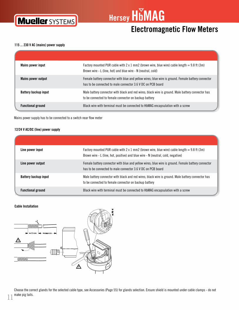
Cable Installation
Mains power supply has to be connected to a switch near flow meter
Choosethecorrectglandsfortheselectedcabletype,seeAccessories(Page55)forglandsselection.Ensureshieldismountedundercableclamps-donotmake pig tails.11

Hersey HbMAG
5.4 Outputs Pulse output connection diagram for HbMAG
Connect red wire to terminal 91, Green/white red wire to terminal 92 and Black wire to terminal 93.
Other radio interface cable has to be a 3-wire cable with a shield connected to HbMAG housing (mounting cable shield is shown to the right).
HbM
AG
Mains or line-powered PUR cable (no shield) has to be mounted under cable clamps. All cable glands have to be sufficiently tightenedtoensureNEMA/IP-rating.
Notice
1 HbMAG Internal connection
2 Passive output - No polarization - Open drain
3 Output A
4 Output B
5 Externalconnection-ConnectionVariant
6 Positive pulse logic
7 Negative pulse logic
8 Signal
1 Power Clock
2 Radio Interface
3 ConnectShieldToEncapsulation
Hot Rod/Mi.Node Itron
1 Red Wire Black Wire
2 Green/White Wire Red Wire
3 Black Wire Unshielded Wire
4 HotRodorMi.Node Endpoint
Pulse output can be configured as volume, alarm or call-up, see Commissioning (Page 13).
Pulse output is not polarized and can be connected for positive or negative logic.
Pull up/down resistor (R) Is selected in relation to power supply voltage (V) and with a max. current (I) of 50 mA.
Note
Pulse output must be connected to equipment complying with Low Voltage Directive in order to be considered safe. The isolation within Hersey pulse output is only a functional isolation.
Figure 5-1 EncoderinterfacecableconnectionsbetweenHerseyHbMag,HotrodandMi.NodeandITRONEndpointwithItroninline connector cable.
It is important that unshielded wire does not touch any metal part of HbMAG housing.
Warning
128.
10.1
0
5.5 Communication Modules Encoder interface connection diagram
GND
Data
129.10.10
12
5.6 Connection of Add-on Modules When the add-on module has been installed, the electrical connections are available on terminal rows 91-97
For more informationRefer to the relevant Quick Start or Operating Instructions available at the Hersey HbMAG literature CD or on the internet at: www.MuellerSystems.com.
Hersey HbMAGElectromagnetic Flow Meters
13
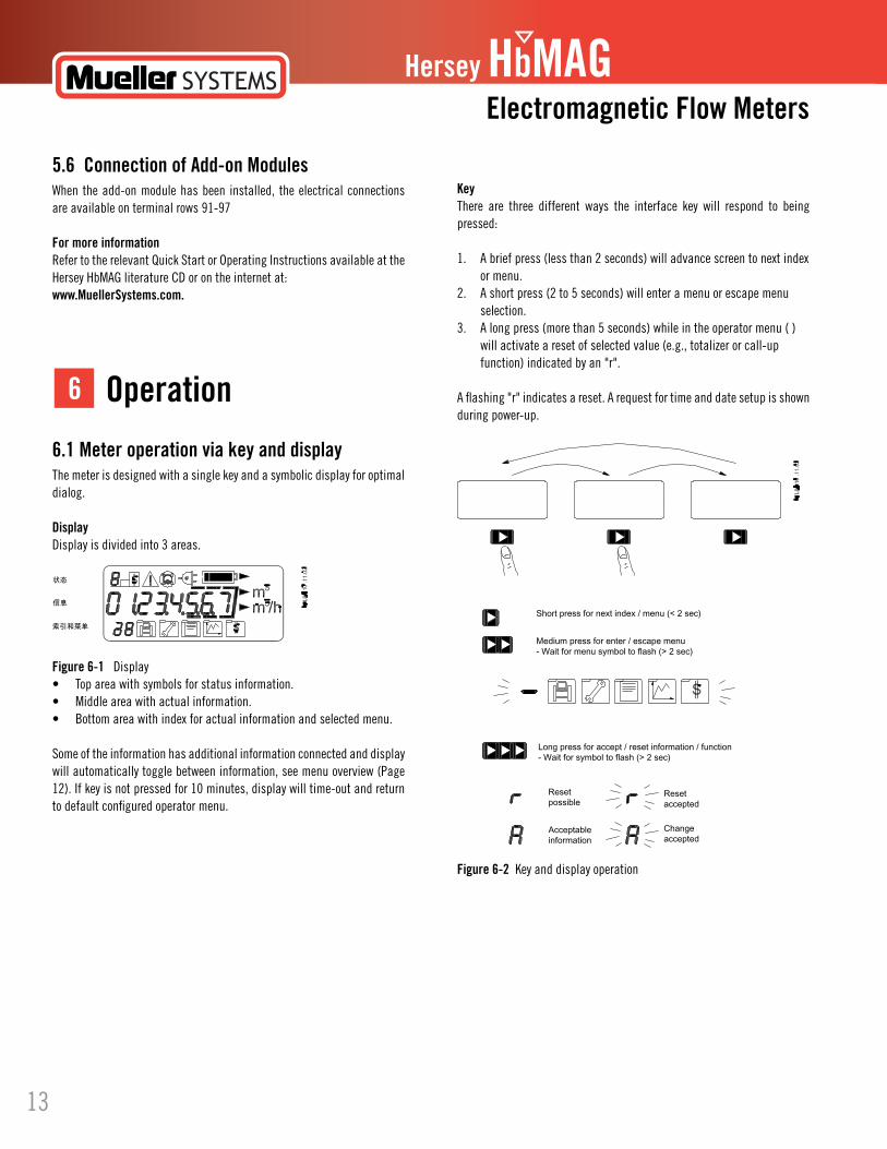
KeyThere are three different ways the interface key will respond to being pressed:
1. A brief press (less than 2 seconds) will advance screen to next index or menu.2. A short press (2 to 5 seconds) will enter a menu or escape menu selection.3. A long press (more than 5 seconds) while in the operator menu ( ) will activate a reset of selected value (e.g., totalizer or call-up function) indicated by an "r".
A flashing "r" indicates a reset. A request for time and date setup is shown during power-up.
Figure 6-2 Key and display operation
6.1 Meter operation via key and display The meter is designed with a single key and a symbolic display for optimal dialog.
DisplayDisplay is divided into 3 areas.
Figure 6-1 Display• Topareawithsymbolsforstatusinformation.• Middleareawithactualinformation.• Bottomareawithindexforactualinformationandselectedmenu.
Some of the information has additional information connected and display will automatically toggle between information, see menu overview (Page 12). If key is not pressed for 10 minutes, display will time-out and return to default configured operator menu.
Operation6
Hersey HbMAG
Figure6-3 Status Bar
Figure 6-4 Menu Bar
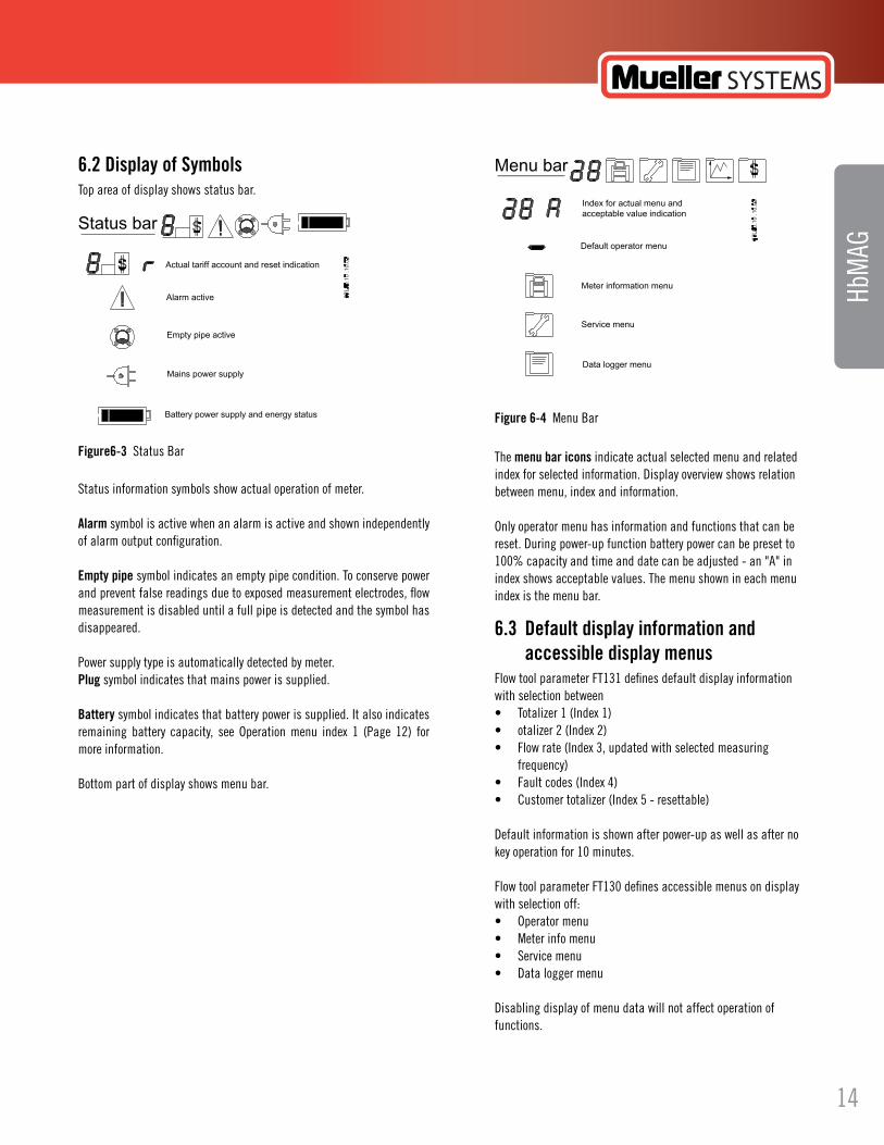
6.2 Display of Symbols Top area of display shows status bar.
Status information symbols show actual operation of meter.
Alarm symbol is active when an alarm is active and shown independently of alarm output configuration.
Empty pipe symbol indicates an empty pipe condition. To conserve power and prevent false readings due to exposed measurement electrodes, flow measurement is disabled until a full pipe is detected and the symbol has disappeared.
Power supply type is automatically detected by meter.Plug symbol indicates that mains power is supplied.
Battery symbol indicates that battery power is supplied. It also indicates remaining battery capacity, see Operation menu index 1 (Page 12) for more information.
Bottom part of display shows menu bar.
HbM
AG
The menu bar icons indicate actual selected menu and related index for selected information. Display overview shows relation between menu, index and information.
Only operator menu has information and functions that can be reset. During power-up function battery power can be preset to 100% capacity and time and date can be adjusted - an "A" in index shows acceptable values. The menu shown in each menu index is the menu bar.
6.3 Default display information and accessible display menus Flow tool parameter FT131 defines default display information with selection between• Totalizer1(Index1)• otalizer2(Index2)• Flowrate(Index3,updatedwithselectedmeasuring frequency)• Faultcodes(Index4)• Customertotalizer(Index5-resettable)
Default information is shown after power-up as well as after no key operation for 10 minutes.
Flow tool parameter FT130 defines accessible menus on display with selection off:• Operatormenu• Meterinfomenu• Servicemenu• Dataloggermenu
Disabling display of menu data will not affect operation of functions.
14
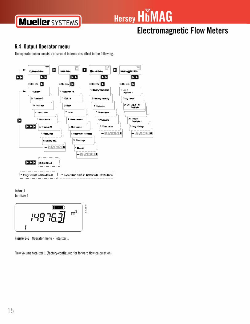
6.4 Output Operator menu The operator menu consists of several indexes described in the following.
Hersey HbMAGElectromagnetic Flow Meters
To see how the outputs work, please see "Output characteristics".
Index 1Totalizer 1
Figure 6-6 Operator menu - Totalizer 1
Flow volume totalizer 1 (factory-configured for forward flow calculation).
15
Hersey HbMAG
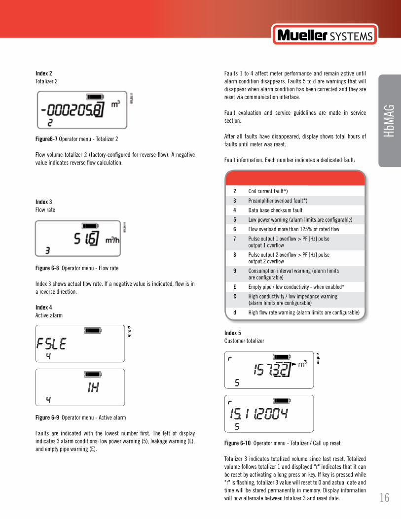
Index 2Totalizer 2
Figure6-7 Operator menu - Totalizer 2
Flow volume totalizer 2 (factory-configured for reverse flow). A negative value indicates reverse flow calculation.
Index 3Flow rate
Figure 6-8 Operator menu - Flow rate
Index 3 shows actual flow rate. If a negative value is indicated, flow is in a reverse direction.
Index 4Active alarm
Figure 6-9 Operator menu - Active alarm
Faults are indicated with the lowest number first. The left of display indicates 3 alarm conditions: low power warning (5), leakage warning (L), andemptypipewarning(E).
HbM
AG
Faults 1 to 4 affect meter performance and remain active until alarm condition disappears. Faults 5 to d are warnings that will disappear when alarm condition has been corrected and they are reset via communication interface.
Fault evaluation and service guidelines are made in service section.
After all faults have disappeared, display shows total hours of faults until meter was reset.
Faultinformation.Eachnumberindicatesadedicatedfault:
Index 5Customer totalizer
Figure 6-10 Operator menu - Totalizer / Call up reset
Totalizer 3 indicates totalized volume since last reset. Totalized volume follows totalizer 1 and displayed "r" indicates that it can be reset by activating a long press on key. If key is pressed while "r" is flashing, totalizer 3 value will reset to 0 and actual date and time will be stored permanently in memory. Display information will now alternate between totalizer 3 and reset date.
2 Coil current fault*)
3 Preamplifier overload fault*)
4 Data base checksum fault
5 Low power warning (alarm limits are configurable)
6 Flow overload more than 125% of rated flow
7 Pulse output 1 overflow > PF [Hz] pulse output 1 overflow
8 Pulse output 2 overflow > PF [Hz] pulse output 2 overflow
9 Consumption interval warning (alarm limits are configurable)
E Emptypipe/lowconductivity-whenenabled*
C High conductivity / low impedance warning (alarm limits are configurable)
d High flow rate warning (alarm limits are configurable)
16

Hersey HbMAGElectromagnetic Flow Meters
Display test
Figure 6-11 Operator menu - Display test
All segments of display are alternately flashed on and off during this test.
Menu selection
Figure 6-12 Operator menu - Menu Selection
If key is pressed shortly (2 to 5 seconds), menu selection will flash indicating that a new selection can be made.
After toggling to desired menu, a short press on key will enable chosen menu.
Index 0 (when active)Call up reset
Figure 6-13 Operator menu - Call Up Reset
Call-up reset window (index 0) is only shown when call-up function is activated. "r" indicates that it can be reset by a long press on key. When releasing key while "r" is flashing, call-up function will be reset and window disappears.
6.5 Data Protection Using hardware keyA hardware key is installed in the HL hole to change protected parameters. The HL hole is located in the front of the PCB board behind the battery. (FT = Flow Tool parameter number)
New Password
FT5 Sensor tube diameter
FT7 Meter No.
FT8 Totalizer unit
FT9 Flow unit
FT10 Qn (Q3)
FT300 Totalizer unit factor
FT301 Flow unit factor
FT302 Pipe size
FT321 Calibration date
FT323 Calibration factor
FT325 Sensor offset
FT332 Max. sensor excitation frequency
Protected Parameters Are:
17
Hersey HbMAG
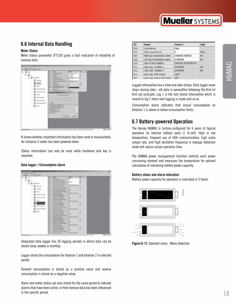
6.6 Internal Data Handling Meter StatusMeter status parameter (FT120) gives a fast indication of reliability of revenue data.
HbM
AG
It shows whether important information has been reset or manipulated, for instance if meter has been powered down.
Status information can only be reset while hardware lock key is mounted.
Data logger / Consumption alarm
Integrated data logger has 26 logging periods in which data can be stored daily, weekly or monthly.
Logger stores the consumption for totalizer 1 and totalizer 2 in selected period.
Forward consumption is stored as a positive value and reverse consumption is stored as a negative value.
Alarm and meter status are also stored for the same period to indicate alarms that have been active, or that revenue data has been influenced in the specific period.
Logged information has a time and date stamp. Data logger never stops storing data - old data is overwritten following the first in/first out principle. Log 1 is the last stored information which is moved to log 2 when next logging is made and so on.
Consumption alarm indicates that actual consumption on totalizer 1 is above or below consumption limits.
6.7 Battery-powered OperationThe Hersey HbMAG is factory-configured for 6 years of typical operation on internal battery pack (1 D-cell). High or low temperature, frequent use of IrDA communication, high pulse output rate, and high excitation frequency in leakage detection mode will reduce actual operation time.
The HbMAG power management function controls each power consuming element and measures the temperature for optimal calculation of remaining battery power capacity.
Battery status and alarm indicationBattery power capacity for operation is indicated in 3 levels.
Figure 6-12 Operator menu - Menu Selection
18
Hersey HbMAGElectromagnetic Flow Meters
• Fullsymbolindicatesbatterycapacityisabovebatteryalarmlevel(%presetparameterFT206).• Lowsymbolindicatesthatbatteryshouldbereplaced;however,measurementwillremainactive.Levelisbasedonapresetalarmlevel.• Whenlowsymbolisflashing,measurementandcommunicationisdisableduntilbatterypackhasbeenreplacedandreset.
"Low battery" is a selectable % parameter (FT206) of 100% full capacity. Meter calculates remaining capacity every four hours, including all consuming elements and influence of temperature changes.
Consumption and operation time calculationBatteryoperationtimedependsonconnectedbatterypackaswellasoperationconditionsofmeter.Every4hourstheadvancedpowermanagementsystemcalculates the real power consumption and remaining operation capacity.
Power consumption calculation includes flow measurement, meter dialog (communication and display) and pulse output.
Temperature is also measured to control and adjust its influence on the battery capacity.
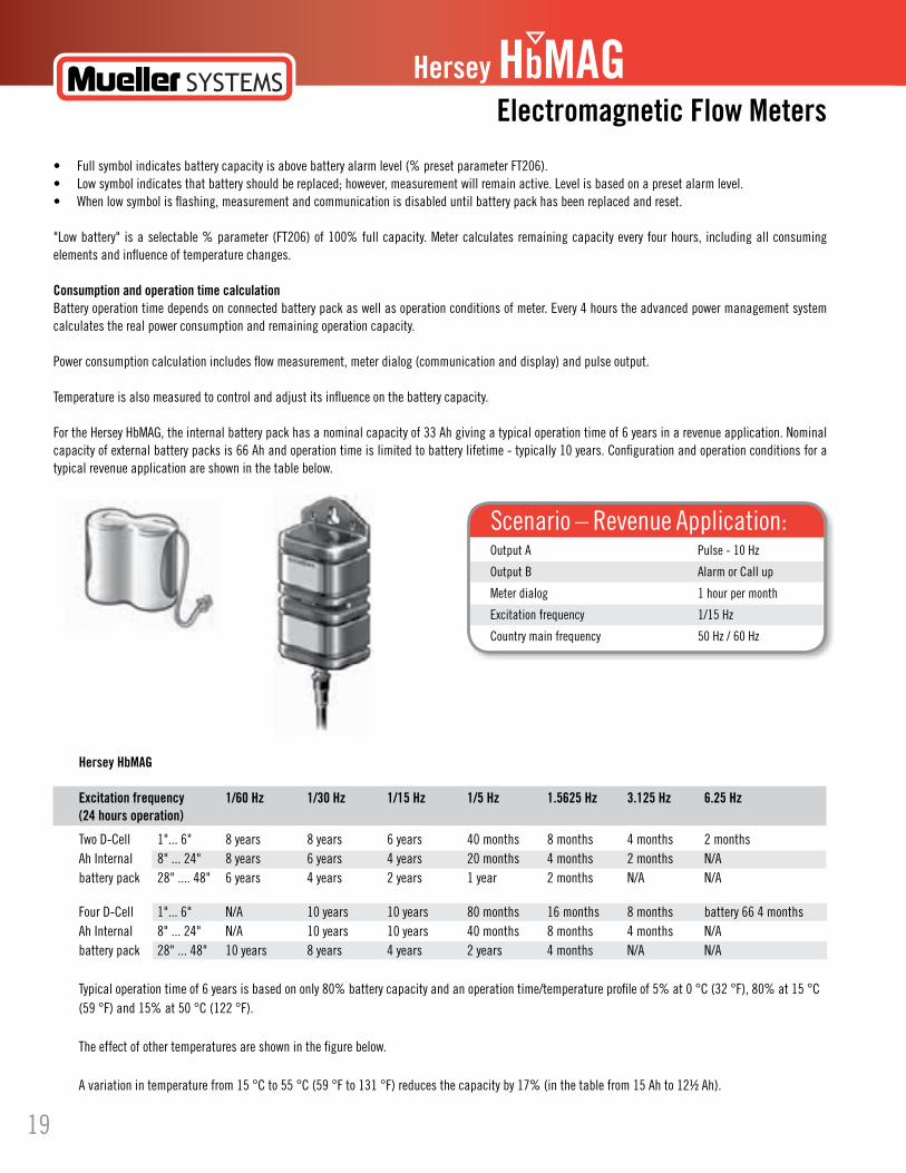
For the Hersey HbMAG, the internal battery pack has a nominal capacity of 33 Ah giving a typical operation time of 6 years in a revenue application. Nominal capacity of external battery packs is 66 Ah and operation time is limited to battery lifetime - typically 10 years. Configuration and operation conditions for a typical revenue application are shown in the table below.
Hersey HbMAG
Excitation frequency 1/60 Hz 1/30 Hz 1/15 Hz 1/5 Hz 1.5625 Hz 3.125 Hz 6.25 Hz(24 hours operation)
Two D-Cell 1"... 6" 8 years 8 years 6 years 40 months 8 months 4 months 2 monthsAh Internal 8" ... 24" 8 years 6 years 4 years 20 months 4 months 2 months N/Abattery pack 28" .... 48" 6 years 4 years 2 years 1 year 2 months N/A N/A
Four D-Cell 1"... 6" N/A 10 years 10 years 80 months 16 months 8 months battery 66 4 monthsAh Internal 8" ... 24" N/A 10 years 10 years 40 months 8 months 4 months N/Abattery pack 28" ... 48" 10 years 8 years 4 years 2 years 4 months N/A N/A
Typical operation time of 6 years is based on only 80% battery capacity and an operation time/temperature profile of 5% at 0 °C (32 °F), 80% at 15 °C (59 °F) and 15% at 50 °C (122 °F).
The effect of other temperatures are shown in the figure below.
A variation in temperature from 15 °C to 55 °C (59 °F to 131 °F) reduces the capacity by 17% (in the table from 15 Ah to 12½ Ah).
Output A Pulse - 10 Hz
Output B Alarm or Call up
Meter dialog 1 hour per month
Excitationfrequency 1/15Hz
Country main frequency 50 Hz / 60 Hz
Scenario – Revenue Application:
19
Hersey HbMAG
HbM
AG
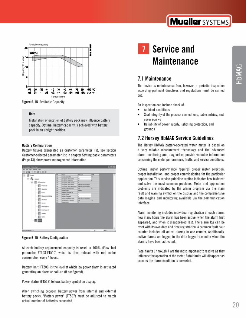
Battery ConfigurationBattery figures (generated as customer parameter list, see section Customer-selected parameter list in chapter Setting basic parameters (Page 43) show power management information.
At each battery replacement capacity is reset to 100% (Flow Tool parameter FT508-FT510) which is then reduced with real meter consumption every 4 hours.
Battery limit (FT206) is the level at which low power alarm is activated generating an alarm or call-up (if configured).
Power status (FT513) follows battery symbol on display.
When switching between battery power from internal and external battery packs, "Battery power" (FT507) must be adjusted to match actual number of batteries connected.
Figure 6-15 Available Capacity
Figure 6-15 Battery Configuration
Note
Installation orientation of battery pack may influence battery capacity. Optimal battery capacity is achieved with battery pack in an upright position.
7.1 Maintenance The device is maintenance-free, however, a periodic inspection according pertinent directives and regulations must be carried out.
An inspection can include check of:• Ambientconditions• Sealintegrityoftheprocessconnections,cableentries,and cover screws• Reliabilityofpowersupply,lightningprotection,and grounds
7.2 Hersey HbMAG Service Guidelines The Hersey HbMAG battery-operated water meter is based on a very reliable measurement technology and the advanced alarm monitoring and diagnostics provide valuable information concerning the meter performance, faults, and service conditions.
Optimal meter performance requires proper meter selection, proper installation, and proper commissioning for the particular application. This service guideline section indicates how to detect and solve the most common problems. Meter and application problems are indicated by the alarm program via the main fault and warning symbol on the display and the comprehensive data logging and monitoring available via the communication interface.
Alarm monitoring includes individual registration of each alarm, how many hours the alarm has been active, when the alarm first appeared, and when it disappeared last. The alarm log can be reset with its own date and time registration. A common fault hour counter includes all active alarms in one counter. Additionally, active alarms are logged in the data logger to monitor when the alarms have been activated.
Fatal faults 1 through 4 are the most important to resolve as they influence the operation of the meter. Fatal faults will disappear as soon as the alarm condition is corrected.
Service andMaintenance
7
20
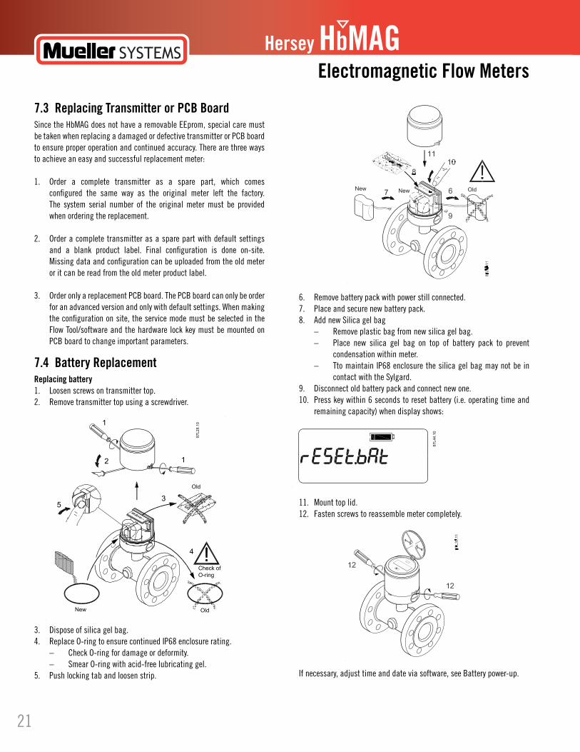
6. Remove battery pack with power still connected.7. Place and secure new battery pack.8. Add new Silica gel bag – Remove plastic bag from new silica gel bag. – Place new silica gel bag on top of battery pack to prevent condensation within meter. – Tto maintain IP68 enclosure the silica gel bag may not be in contact with the Sylgard.9. Disconnect old battery pack and connect new one.10. Press key within 6 seconds to reset battery (i.e. operating time and remaining capacity) when display shows:
11. Mount top lid.12. Fasten screws to reassemble meter completely.
If necessary, adjust time and date via software, see Battery power-up.
Hersey HbMAGElectromagnetic Flow Meters
7.3 Replacing Transmitter or PCB Board SincetheHbMAGdoesnothavearemovableEEprom,specialcaremustbe taken when replacing a damaged or defective transmitter or PCB board to ensure proper operation and continued accuracy. There are three ways to achieve an easy and successful replacement meter:
1. Order a complete transmitter as a spare part, which comes configured the same way as the original meter left the factory. The system serial number of the original meter must be provided when ordering the replacement.
2. Order a complete transmitter as a spare part with default settings and a blank product label. Final configuration is done on-site. Missing data and configuration can be uploaded from the old meter or it can be read from the old meter product label.
3. Order only a replacement PCB board. The PCB board can only be order for an advanced version and only with default settings. When making the configuration on site, the service mode must be selected in the Flow Tool/software and the hardware lock key must be mounted on PCB board to change important parameters.
7.4 Battery Replacement Replacing battery1. Loosen screws on transmitter top.2. Remove transmitter top using a screwdriver.
3. Dispose of silica gel bag.4. Replace O-ring to ensure continued IP68 enclosure rating. – Check O-ring for damage or deformity. – Smear O-ring with acid-free lubricating gel.5. Push locking tab and loosen strip.
21

Hersey HbMAG
7.5 Power up with battery reset, date and time set up
When new batteries have been installed, power-up procedure will enable resetting battery capacity and setting up date and time. Battery capacity reset, date and time can also be corrected via functions FT508 and FT200.
When battery plug is connected, meter will display meter version for 10 seconds. Display will then show "rESEt.bAt" indicatingthe option to reset internal battery power calculation. To execute reset, press key within 6 seconds. If key is not pressed, meter will proceed to set date, set clock, and finally normal operation mode.
If key is pressed within reset battery time, display will indicate "Accept" to ensure that reset should take place. Reset will take place only if key is pressed again within the next 6 seconds. If not, normal operation will begin.
For setting up date and time, the different key function must be used - see Operator menu index 1 (Page 54). An "A" indicates an acceptable value and a flashing "A" indicates that value is stored when key is released.
Reset function also sets actual date as battery replacement date.
HbM
AG
7.6 Verification Verification mode increases measurement frequency to provide maximum measurements per second. This function is especially useful to minimize calibration rig time when validating flowmeter accuracy. Frame around digits will blink slowly to indicate that verification mode is enabled. Maximum pulse rate on output A is increased to 1 kHz and pulse width is set to 1 ms. When verification mode is exited the previous pulse setting is restored. Pulse widths other than 1 ms can be selected by storing new pulse values. This setting remains when verification mode is exited.
Activation of verification modeVerification mode is enabled in one of the following ways:• Pressingpushbuttonthroughholeinfrontscreenor• Writinginteger‘1’toparameterregister"CalibrationMode" (FT320).
Verification modeThe following indicate that meter is in verification mode:• FramesurroundingdigitsinLCDstartsflashing.• Excitationfrequencyissettomaximumallowablefrequency. – (ExcitationFreqNo=ExcitationFreqNoLimit)• Resolutionindisplayissetto3digitsafterdecimalpoint. – (DecimalPoint = 3)
Deactivation of verification modeVerification mode is deactivated in one of the following ways:• Pressingpushbuttonagain.• Writinginteger‘0’toparameterregister"CalibrationMode" (FT320).
Verification mode automatically stops if not manually deactivated within 4 hours.
22

7.9 Return procedures Contact Mueller Systems Customer Care at 800-323-8584 or your local Mueller Systems sales representative or distributor to arrange all product returns and dispositions. No returns will be accepted without proper documentation and authorization.
7.10 Battery Disposal Please check your local ordinances for information concerning battery disposal and follow all acceptable practices.
Technical Support If you have any technical questions about the device described in these Operating Instructions and do not find the right answers, you can contact Technical Support:
• ViatheInternetusingtheContactUs:(http://www.muellersystems.com)• Phone:800-323-8584or704-278-2221
Service & Support on the Internet In addition to our documentation, we offer comprehensive product listings online on the Internet at: Service and support (http://www.muellersystems.com/)
There you will find:• Thelatestproductinformation• AMR/AMISystemsinformationforWater,Gas,andElectric• News,EventsandTraining• HistoryandCaseStudies• ResourceLibrary
Additional Support Please contact your local Mueller Systems representative if you have additional questions call Customer Care at 800-323-8584
Hersey HbMAGElectromagnetic Flow Meters
7.7 Using Sealing The Hersey HbMAG can be sealed to provide tamper detection.Sealing device
7.8 Technical Support
Figure 8-1 HbMAG user sealing (A)
Note
Mueller Systems defines sensors as non-repairable products.
Repair and service must be carried out by approved Mueller Systems personnel only.
Caution
8.1 Fault Codes Error systemThe Hersey HbMAG can detect and report 14 different faults.
The faults are divided into two types: Fatal errors and Warnings.
Fatal errors: Faults 2, 3, and 4
Warnings: Faults 5, 6, 7, 8, 9, E, C, d, and 14
Troubleshooting/FAQs8
23
Hersey HbMAG
HbM
AG
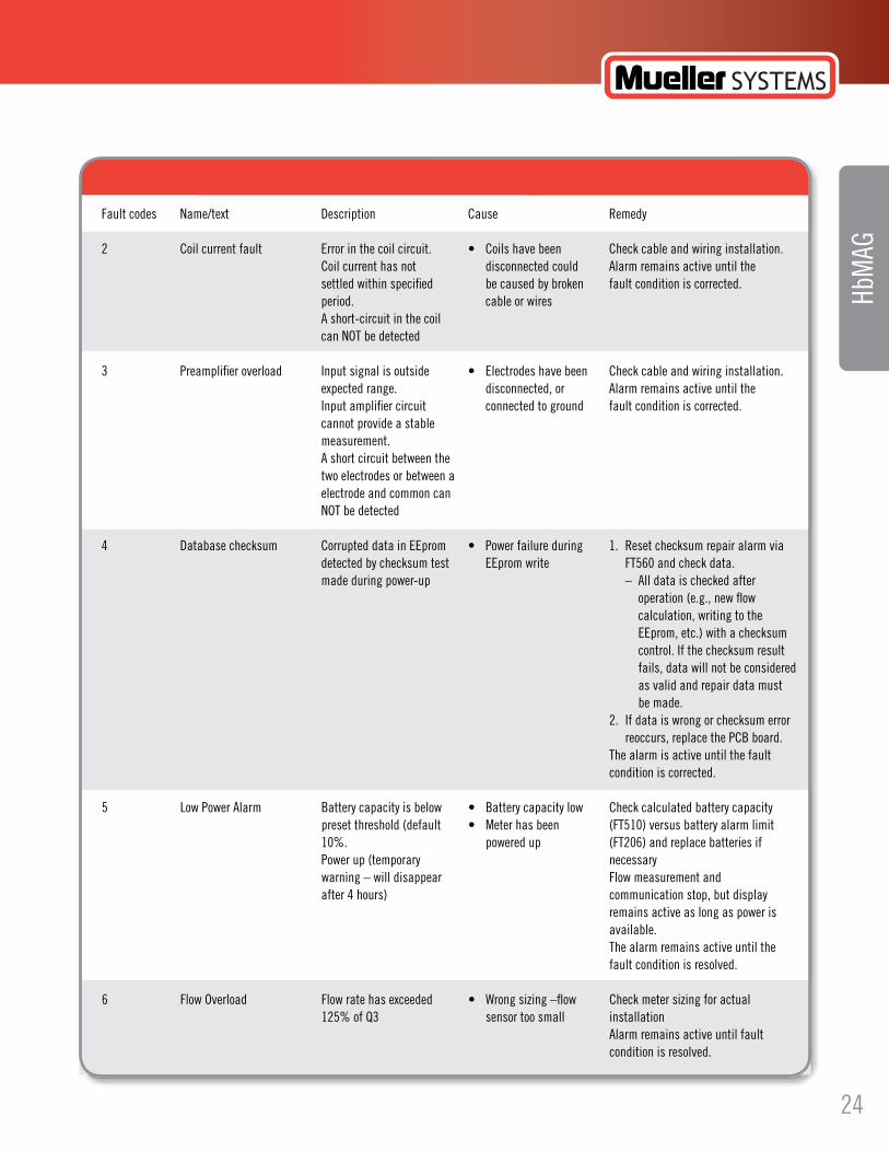
Fault codes Name/text Description Cause Remedy 2 Coilcurrentfault Errorinthecoilcircuit. • Coilshavebeen Checkcableandwiringinstallation. Coil current has not disconnected could Alarm remains active until the settled within specified be caused by broken fault condition is corrected. period. cable or wires A short-circuit in the coil can NOT be detected
3 Preamplifieroverload Inputsignalisoutside • Electrodeshavebeen Checkcableandwiringinstallation. expected range. disconnected, or Alarm remains active until the Input amplifier circuit connected to ground fault condition is corrected. cannot provide a stable measurement. A short circuit between the two electrodes or between a electrode and common can NOT be detected
4 Databasechecksum CorrupteddatainEEprom • Powerfailureduring 1. Resetchecksumrepairalarmvia detectedbychecksumtest EEpromwrite FT560andcheckdata. made during power-up – All data is checked after operation (e.g., new flow calculation, writing to the EEprom,etc.)withachecksum control. If the checksum result fails, data will not be considered as valid and repair data must be made. 2. If data is wrong or checksum error reoccurs, replace the PCB board. The alarm is active until the fault condition is corrected.
5 LowPowerAlarm Batterycapacityisbelow • Batterycapacitylow Checkcalculatedbatterycapacity presetthreshold(default • Meterhasbeen (FT510)versusbatteryalarmlimit 10%. powered up (FT206) and replace batteries if Power up (temporary necessary warning – will disappear Flow measurement and after 4 hours) communication stop, but display remains active as long as power is available. The alarm remains active until the fault condition is resolved.
6 FlowOverload Flowratehasexceeded • Wrongsizing–flow Checkmetersizingforactual 125% of Q3 sensor too small installation Alarm remains active until fault condition is resolved.
24

Hersey HbMAGElectromagnetic Flow Meters
Fault codes Name/text Description Cause Remedy 7 PulseAoverload DutycycleofoutputA • Wrongsettingsfor Changevolumeperpulsetoahighervalue- has exceeded maximum output A see Technical data for pulse selection. possible of 50 Reminder: basic version is limited to 50 Hz maximum; advanced version to 100 Hz maximum. The alarm remains active until output pulse rate drops below maximum pulse rate.
8 PulseBoverload DutycycleofoutputB • Wrongsettingsfor Changevolumeperpulsetoahighervalue- has exceeded maximum output B see Technical data for pulse selection. possible of 50 Reminder: basic version is limited to 50 Hz maximum; advanced version to 100 Hz maximum. The alarm remains active until output pulse rate drops below maximum pulse rate.
9 Consumptioninterval Accumulatedvolumeon • Flowratehigheror Checkdataloggervaluesandconsumption totalizer 1 during data log lower than expected limit. periodhasexceededthe • Wrongparameter Alarmremainsactiveuntilitismanually too low or too high setup reset via FT209. consumption limit
E EmptyPipe Measuredelectrode • Pipenotfilledwith Ensuresensorisfilledwithwater. impedance has exceeded water Alarm remains active until fault condition the empty-pipe detection is resolved level (FT540 & FT541 & FT334)
C LowConductivity Measuredelectrode • Waterispolluted Alarmisactiveuntilwaterresistance impedence is below low (e.g. saltwater in is above low media alarm limit. conductivity threshold fresh water) (FT542), i.e. water has a high conductivity
d FlowLimit Theflowrateisgreaterthan • Waternetworkfailure- Alarmremainsactiveuntilflowratedrops the flow alarm limit FT553). pipe burst below flow alarm limit
ReverseFlow Flowrateisbelowapreset • Waternetworkfailure- threshold(default-1E9) non-returnvalveis broken
Note
Reset of fault log (FT204) also resets all alarms. Once reset, only active alarms become visible again.
25

Hersey HbMAG
HbM
AG
8.2 Built-in Functions Empty pipe detectionElectrodeimpedanceismeasuredwith800Hzat50Hzmainsfrequency(960 Hz at 60 Hz mains frequency). This is done by toggling the electrode control pin every 6 respectively 5 samples – the sample frequency is 9600 Hz. The impedance value is averaged over 100 measurements. The electrode impedance A and B are measured in turns.
The unfiltered impedance value (a fast warning indication) is compared with a limit and the empty pipe warning is reported when it exceeds this limit – but only if the detection is ON and if there is no overload failure.
During empty pipe detection the coil current is held OFF and the flow value is forced zero.
DefaultsettingsforElectrodeImpedanceLimitis25000ohmcorrespondingto a water conductivity of 20 µS/cm (10 000 ohm ≈ 50 µS/cm)
Coil-current testWhen H-bridge is turned and just before making samples (4 times each measurement), the coil current is checked via a comparator. If the coil current is not settled, a failure is reported.
During coil current failure the flow value is forced zero.
Preamplifier testOverload is possible both from the AD conversion of sensor signal and from the pre-amplifier. These checks are made at each sample and if one of the sample fails with an overload, this measurement is cancelled and a failure is reported.
During overload detection the coil current is held OFF and the flow value is forced zero.
Checking facilitiesThe Hersey HbMAG is equipped with checking facilities of types P, I, and N. (2.5.5 in OIML R49). The automatic checks are performed without operator intervention.
Type P permanent checking facilities are automatic checks performed constantly during meter operation. They include:• Coilcurrenttest• Preamplifiertest• Emptypipetest• Flowoverload• Pulseoverload
Type I intermittent checking facilities are automatic checks performed at certain time intervals or per fixed number of measurements. They include:• Checksum calculation (10 min. interval on totalizer checksum)• Insulationtest(minimum24hourinterval)• Batterycapacitycheck(4hoursinterval)
Type N non-automatic checking facilities are checks that are not performed automatically including all other diagnosis functions in the Hersey HbMAG.
8.3 Flow SimulationsThe Hersey HbMAG has a built-in flow simulator (FT551 & FT552) to verify and adjust pulse output to any connected device or system.
Totalized values are changed during simulation and actual flow is NOT measured.
Simulation continues until it is manually turned off (nor-mal operation restored).
Warning
26
9.2 Sensor Technical Specifications
Hersey HbMAGElectromagnetic Flow Meters
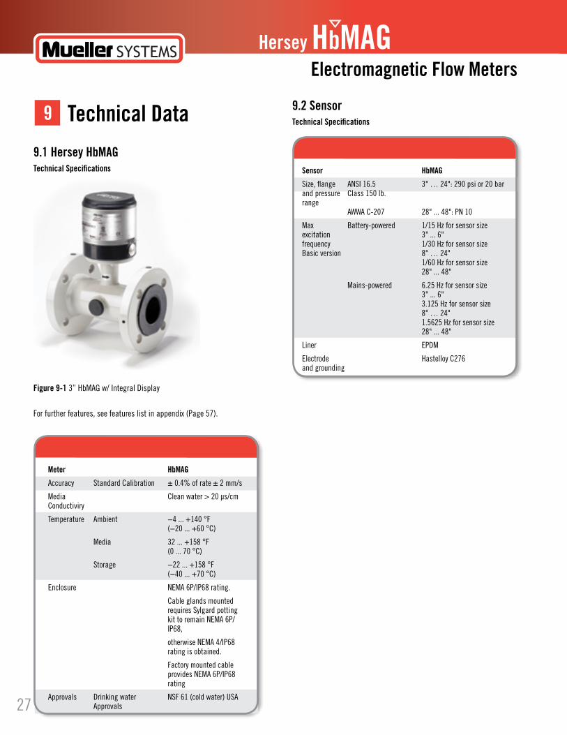
9.1 Hersey HbMAG Technical Specifications
For further features, see features list in appendix (Page 57).
Technical Data9
Figure 9-1 3” HbMAG w/ Integral Display
Meter HbMAG
Accuracy Standard Calibration ± 0.4% of rate ± 2 mm/s
Media Clean water > 20 µs/cm Conductiviry
Temperature Ambient −4 ... +140 °F (−20 ... +60 °C)
Media 32 ... +158 °F (0 ... 70 °C)
Storage −22 ... +158 °F (−40 ... +70 °C)
Enclosure NEMA6P/IP68rating.
Cable glands mounted requires Sylgard potting kittoremainNEMA6P/ IP68,
otherwiseNEMA4/IP68 rating is obtained.
Factory mounted cable providesNEMA6P/IP68 rating
Approvals Drinking water NSF 61 (cold water) USA Approvals
Sensor HbMAG
Size, flange ANSI 16.5 3" … 24": 290 psi or 20 bar and pressure Class 150 lb. range AWWA C-207 28" ... 48": PN 10
Max Battery-powered 1/15 Hz for sensor size excitation 3" ... 6" frequency 1/30 Hz for sensor size Basic version 8" … 24" 1/60 Hz for sensor size 28" ... 48"
Mains-powered 6.25 Hz for sensor size 3" ... 6" 3.125 Hz for sensor size 8" … 24" 1.5625 Hz for sensor size 28" ... 48"
Liner EPDM
Electrode HastelloyC276 and grounding
27

Hersey HbMAG
9.3 Transmitter
HbM
AGTransmitter HbMAG
Installation Integral(compact)orremotewithfactory-mountedcablein25’lengthswithNEMA 6P/ IP68 connectors.
Connection is made at the transmitter bottom.
Material Top housing Stainless steel (AISI 316)
Bottom Coated brass
Wall mounting bracket Stainless steel (AISI 304).
Cable entries 2 x M20 (one gland for one cable of size 6 … 8 mm (0.02 ... 0.026 ft) is included in the standard delivery)
Display and key Display 8 digits for main information. Index, menu and status symbols for dedicated information
Key For toggling through information and resetting of customer totalizer and call-up function
Menus Selectable default information and accessible menus: - Operator - Meter - Service - Data Logger
Resolution Totalized information can be displayed with 1, 2 or 3 decimals or automatic adjustment for maximum resolution
Flow unit Mexico, Canada std. Volume: m3 Flow rate:m3/h
US std. Volume: Gallon or CF Flow rate: GPM
Other selectable units Volume: m3 x 100, l x 100, G x 100, G x 1000, MG, CF x 100, CF x 1000, AF, Al, kl
Flow rate: m3/min, m3/d, l/s, l/min, l/h, GPS, GPH, GPD, MGD, CFS, CFM, CFH
Units other than G, CF and GPM (ordered from factory or manually configured onsite by changing scaling factors) are shown by a label on the display
Digital output Nos. 2 passive outputs (MOS), individually galvanically isolated
Load Max. ± 35 V DC, 50 mA short circuit protected
28

Hersey HbMAGElectromagnetic Flow Meters
Transmitter HbMAG
Digital output Output A Programmable as: Pulse volume Forward Reverse Forward/net Reverse/net
Output B Programmable as: Pulse volume Forward Reverse Forward/net Reverse/net Alarm Call-up
Pulse rate Max. 50 Hz
Pulse width 5, 10, 50, 100, 500 ms
Communication IrDA Standard integrated infrared communication interface with MODBUS RTU protocol
Add-onmodules Encoderinterfacemodule(forHotRod,Mi.Net,ItronEndpoints)"Herseyprotocol"
Power Supply HbMAG
Battery power supply 1) Auto-detection of power source with displayed symbol for remaining power.
In battery mode, excitation frequency is manually selected
Internal battery pack 21D_Cell 3.6 V / 16 Ah
Internal battery pack 2 D_Cell 3.6 V / 33 Ah
Externalbatterypack 4D_Cell3.6V/66Ah
12-24 V AC/DC power supply Input voltage range 12/24 V AC/DC (10 ... 32 V DC)
Power consumption 2 VA
Isolation Class II
Fuse 1000 mA T - Not replaceable
Short circuit protection Module is protected from short circuit on the output connector. Both during mains and backup supply
9.4 Power Supply Technical Specifications
29

Hersey HbMAG
Power Supply HbMAG
115 ... 230 V AC mains supply Input voltage range 115 ... 230 V AC, +15% to −20%, 50-60 Hz
Power consumption 2 VA
Isolation Class II
Fuse 250 mA T - Not replaceable
Short circuit protection Module is protected from short circuit on the output connector. Both during mains and backup supply
Input cable for 12/24 V AC/DC Factory-mounted PUR cable 2 x 1 mm2 (brown, blue) and 115 ... 230 V AC power supply Length = 9.8 ft
Resistance Sunlight and water
Outer diameter 0.28" (7 mm)
Rated voltage 300 ... 500 V AC
Testing voltage 2000 V AC
Temperature range Fixed laying: -40 ... 194 °F (−40 ... +90 °C) Flexible application: -22 ... 176 °F (−30 ... +80 °C)
Bending radius Min. 1.1” (28 mm) (fixed installation)
Pulling force Max. 200 N
Output Female connector
Backup battery Male connector
1) Lithium batteries are subject to special transportation regulations according to United Nations "Regulation of Dangerous Goods, UN 3090 and UN 3091". Special transport documentation is required to observe these regulations. This may influence both transport time and costs.
30

Output B as call-up output
Hersey HbMAGElectromagnetic Flow Meters
HbMAGWhen output A or B is configured as volume per pulse, the output delivers a pulse when the preset volume based on either Forward/Reverse or Net Forward/Net Reverse flow has passed the sensor in the selected direction. The volume per pulse is freely scalable, from 0.000001 to 10 000 units per pulse, and should not exceed the pulse rate of the output configuration table.
Output B as alarm output
HbMAGWhen output B is configured as an "alarm" output, it will follow the internal alarms that were previously chosen in the Alarm Configuration List.
Hersey HbMAGWhen output B is configured as an "call-up" output, it will follow the internal alarms that were previously chosen in the Alarm Configuration List.
Factory regional settings
When output B is configured as "call-up", the output is activated by an alarm condition and remains on until it is reset via meter display key or communication interface.
A new alarm will not activate a "call-up" function if the "call-up" function is still active from a previous alarm.
9.5 Output CharacteristicsThis chapter describes how the Hersey HbMAG outputs work.
Output A and B as pulse volume
PW 5, 10, 50 100 & 500 mS
1 Forward PR Pulse rate
2 Reverse PF Pulse frequency
3 Cut-off PW Pulse width
1 Alarm outputs
2 Alarm status
3 On - Off
4 NoError
1 Call up output
2 Call up reset
3 Call up status
4 On - Off
Note
Alarm output is inverted to a pulse output providing an alarm if power disappears or cable connection is interrupted.
Note
Like alarm output, call-up output inverts to a pulse output providing a call-up if power disappears or cable connection is interrupted.
Note
Call-up output is inverted to a pulse output providing an alarm if power disappears or cable connection is interrupted.
size (inch) Pulse Mexico, USA width ms Canada m3 Gallons
3", 4", 6" 50 0.1 10
8", 10", 12", 14", 50 1 100 16", 18", 20"
24", 28", 30", 32", 50 10 100 36", 40", 42", 44", 48"
31

Hersey HbMAG
Pulse A is set to ON - Forward flow. Pulse B is set to Alarm.
Pulse output, volume selection (HbMAG)
PW = pulse width
HbM
AG
Note
You can select other units than the defaults via the software. The pulse output will only be enabled if the meter selected is ordered with the pulse output as an option.
Note
Display volume for 5 ms pulse width is based on a basic version with maximum 50 Hz pulse output rate.
The calculated numbers of pulses are an average of the measuring period.
DN (inches) Max. flow rate Guidelines for min. volume per pulse at Qn Qn (Q3) M3 Volume [m3] = Qn [m3/s] * (2*PW [s])
5 ms PW m3 10 ms PW m3 50 ms PW m3 50 ms PW gallon 50 ms PW Ml 100 ms PW m3 500 ms PW m3 [50Hz] [50Hz] [10Hz] [10Hz] [10Hz] [5Hz] [1Hz]
3” 80 160 0.0004 0.0009 0.004 1.174 0.000004 0.009 0.044
4” 100 250 0.0007 0.0014 0.007 1.835 0.000007 0.014 0.069
5” 125 400 0.0011 0.0022 0.011 2.935 0.000011 0.022 0.111
6” 150 630 0.0018 0.0035 0.018 4.623 0.000018 0.035 0.175
8” 200 1000 0.0028 0.0056 0.028 7.338 0.000028 0.056 0.278
10” 250 1600 0.0044 0.0089 0.044 11.741 0.000044 0.089 0.444
12” 300 2500 0.0069 0.0139 0.069 18.345 0.000069 0.139 0.694
14” 350 3463 0.0096 0.0192 0.096 25.412 0.000096 0.192 0.962
16” 400 4523 0.0126 0.0251 0.126 33.190 0.000126 0.251 1.256
18” 450 5725 0.0159 0.0318 0.159 42.010 0.000159 0.318 1.590
22” 500 7068 0.0196 0.0393 0.196 51.865 0.000196 0.393 1.963
24” 600 10178 0.0283 0.0565 0.283 74.687 0.000283 0.565 2.827
28” 700 13854 0.0385 0.0770 0.385 101.662 0.000385 0.770 3.848
30” 750 15904 0.0442 0.0884 0.442 116.705 0.000442 0.884 4.418
32” 800 18095 0.0503 0.1005 0.503 132.782 0.000503 1.005 5.026
36” 900 22902 0.0636 0.1272 0.636 168.057 0.000636 1.272 6.362
40” 1000 28274 0.0785 0.1571 0.785 207.477 0.000785 1.571 7.854
42” 1050 31175 0.0866 0.1732 0.866 228.750 0.000866 1.732 8.659
44” 1100 34211 0.0950 0.1901 0.950 251.043 0.000950 1.901 9.503
48” 1200 40715 0.1131 0.2262 1.131 298.770 0.001131 2.262 11.310
32

Hersey HbMAGElectromagnetic Flow Meters
Net flow outputThe HbMAG has a special net pulse output that includes bi-directional flow calculations.
The example shows that over time, the net pulse output indicates the bi-directional totalizer as calculated internally. The same principle applies for forward and reverse flow calculation. By changing the status of the pulse output, the internal pulse calculator will be reset.
Flow Net totalizer Pulse output forward Uni-directional mode Pulse output net forward Bi-directional mode in meter display Volume [m3] Volume [m3] (Bi-directional)
Volume [m3] Internal calculation Delivered volume Internal calculation Delivered volume
0 - 0 0 0
10 - 10 0 10
−2 - 0 -12 0
18 - 20 −12+20= 8
Total accounted volume 18F 30F 18F [m3] Forward/Reverse
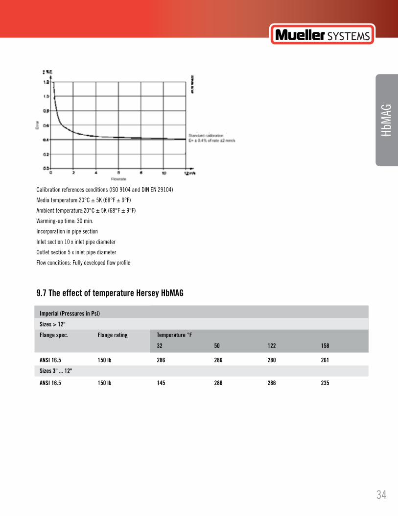
9.6 Meter UncertaintyTo ensure continuous accurate measurement, flow meters must be calibrated. The calibration is conducted at facilities with traceable instruments referring directly to the physical unit of measurement according to the International System of Units (SI).
Therefore, the calibration certificate ensures recognition of the test results worldwide, including the US (NIST traceability). Accredited calibrations are offered assured to ISO 17025 in the flow range from 0.0001 m³/h to 10 000 m³/h. The laboratories are accredited laboratories and recognized by ILAC MRA (International Laboratory Accreditation Corporation
- Mutual Recognition Arrangement) ensuring international traceability and recognition of the test results worldwide.A calibration certificate is shipped with every sensor and calibration
The selected calibration determines the accuracy of the water meter. An HbMAG calibration results in max. ±0.4% of rate ±2 mm/s uncertainty.
33
Hersey HbMAG
HbM
AG
Calibrationreferencesconditions(ISO9104andDINEN29104)
Media temperature:20°C ± 5K (68°F ± 9°F)
Ambient temperature:20°C ± 5K (68°F ± 9°F)
Warming-up time: 30 min.
Incorporation in pipe section
Inlet section 10 x inlet pipe diameter
Outlet section 5 x inlet pipe diameter
Flow conditions: Fully developed flow profile
9.7 The effect of temperature Hersey HbMAG
Imperial (Pressures in Psi)
Sizes > 12"
Flange spec. Flange rating Temperature °F
32 50 122 158
ANSI 16.5 150 lb 286 286 280 261
Sizes 3" ... 12"
ANSI 16.5 150 lb 145 286 286 235
34

Hersey HbMAGElectromagnetic Flow Meters
9.8 Dimensions and DrawingsMeter Dimensions
Dimensions for HbMAG
1) For remote version the sensor weight is reduced with 4.5 lb (2 kg) 2) See flange table (Page 38)
Nominal size DN A L, lenghts D, diameter Approx. Weight 1)
ANSI 16.5 AWWA DI D CI.150
Inch (mm) Inch (mm) inch inch mm (inch) lbs kg
3 (80) 8.2 (207) 7.9 N/A 67 (2.64) 2) 34 15
4 (100) 8.5 (214) 9.8 N/A 81 (3.19) 2) 38 17
5 (125) 8.9 (224) 9.8 N/A 101 (3.98) 2) 50 22
6 (150) 9.5 (239) 11.8 N/A 131 (5.16) 2) 63 28
8 (200) 10.5 (264) 13.8 N/A 169 (6.65) 2) 113 50
10 (250) 11.5 (291) 17.7 N/A 212 (8.35) 2) 160 71
12 (300) 12.6 (317) 19.7 N/A 265 (10.43) 2) 198 88
14 (350) 14.6 (369) 21.7 N/A 350 (13.78) 2) 279 127
16 (400) 15.6 (394) 23.6 N/A 400 (15.75) 2) 318 145
18 (450) 16.8 (425) 23.6 N/A 450 (17.72) 2) 394 175
20 (500) 17.8 (450) 26.8 N/A 500 (19.68) 2) 494 225
24 (600) 19.8 (501) 32.3 N/A 600 (23.62) 2) 747 340
28 (700) 21.4 (544) N/A 27.6 700 (27.55) 2) 694 316
30 (750) 22.5 (571) N/A 29.5 750 (29.52) 2) N/A N/A
32 (800) 23.9 (606) N/A 31.5 800 (31.49) 2) 1045 398
36 (900) 25.7 (653) N/A 35.4 900 (35.42) 2) 1045 476
40 (1000) 27.7 (704) N/A 39.4 1000 (39.36) 2) 1322 602
42 (1050) 27.7 (704) N/A 41.3 1050 (41.33) 2) N/A N/A
44 (1100) 29.7 (755) N/A 43.3 1100 (43.30) 2) N/A N/A
48 (1200) 31.9 (810) N/A 47.2 1200 (47.23 2) 1996 887
35

Hersey HbMAG
HbM
AG
Remote Version
Flange Dimensions
HbMAG
Dimensions Inches Bolting
Size D PCD T B Holes Bolts
ANSI Class 150
3" 7.5 6 0.94 0.75 4 5/8"
4" 9 7.5 0.94 0.75 8 5/8"
6" 11 9.5 1 0.88 8 3/4"
8" 13.5 11.75 1.12 0.88 8 3/4"
10" 16 14.25 1.19 1.00 12 7/8"
12" 19 17 1.25 1.00 12 7/8"
14" 21 18.75 1.38 1.12 12 1"
16" 23.5 21.25 1.44 1.12 16 1"
18" 25 22.75 1.56 1.25 16 1 1/8"
20" 27.5 25 1.69 1.25 20 1 1/8"
24" 32 29.5 1.88 1.38 20 1 1/4"
Figure 9-2 Dimensions in mm (inch), weight 3.5 kg (8 lbs)
36

Hersey HbMAGElectromagnetic Flow Meters
Figure 10-3 Flat Ring
Note
Physical orientation of battery pack may influence battery capacity. Optimal battery capacity is achieved with battery pack in an upright position as shown.
Ground RingsSizes 3”…12”
External Battery Pack
* Worn industry batteries may be disposed at the manufacturer or the importer who originally marketed the battery, or where new batteries are bought.
Dimensions in mm (inch), weight 3.5 kg (8 lbs)
37
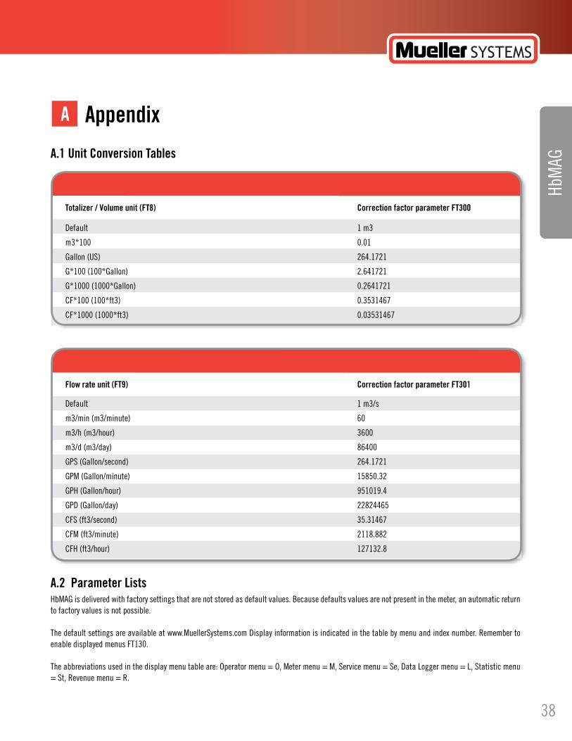
A.2 Parameter Lists HbMAG is delivered with factory settings that are not stored as default values. Because defaults values are not present in the meter, an automatic return to factory values is not possible.
The default settings are available at www.MuellerSystems.com Display information is indicated in the table by menu and index number. Remember to enable displayed menus FT130.
The abbreviations used in the display menu table are: Operator menu = O, Meter menu = M, Service menu = Se, Data Logger menu = L, Statistic menu = St, Revenue menu = R.
Hersey HbMAG
HbM
AGA.1 Unit Conversion Tables
AppendixA
Totalizer / Volume unit (FT8) Correction factor parameter FT300
Default 1 m3
m3*100 0.01
Gallon (US) 264.1721
G*100 (100*Gallon) 2.641721
G*1000 (1000*Gallon) 0.2641721
CF*100 (100*ft3) 0.3531467
CF*1000 (1000*ft3) 0.03531467
Flow rate unit (FT9) Correction factor parameter FT301
Default 1 m3/s
m3/min (m3/minute) 60
m3/h (m3/hour) 3600
m3/d (m3/day) 86400
GPS (Gallon/second) 264.1721
GPM (Gallon/minute) 15850.32
GPH (Gallon/hour) 951019.4
GPD (Gallon/day) 22824465
CFS (ft3/second) 35.31467
CFM (ft3/minute) 2118.882
CFH (ft3/hour) 127132.8
38
Hersey HbMAGElectromagnetic Flow Meters
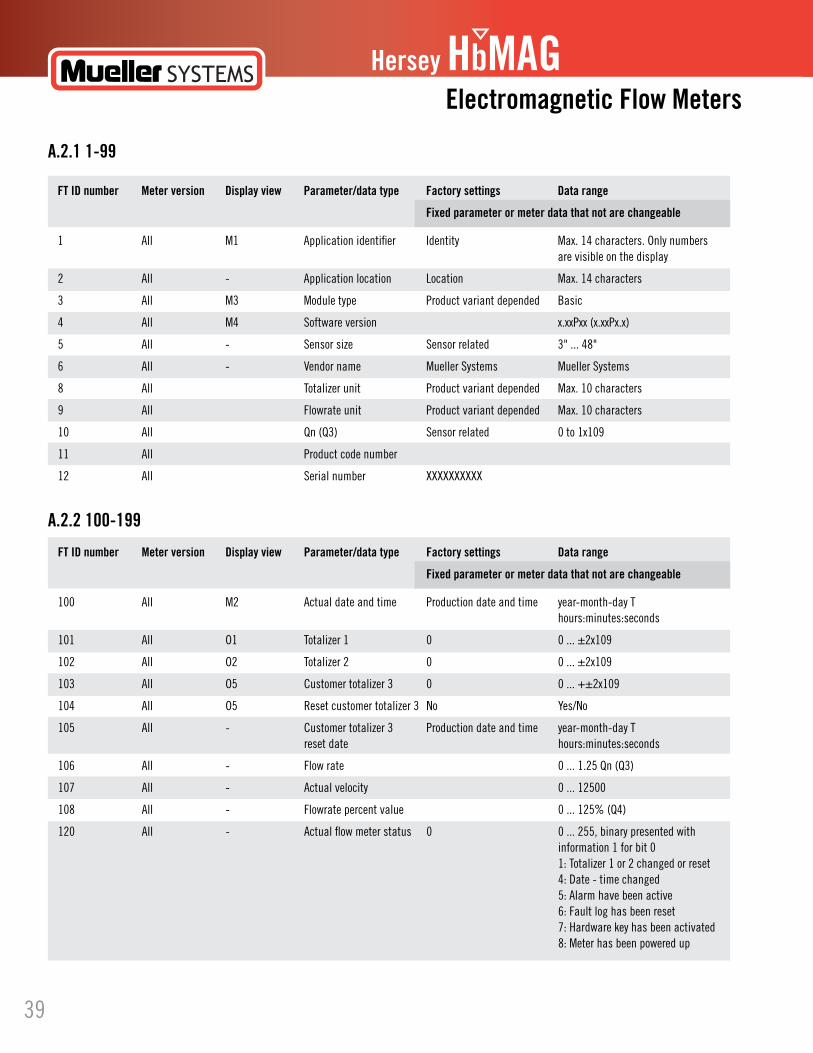
A.2.1 1-99
A.2.2 100-199
FT ID number Meter version Display view Parameter/data type Factory settings Data range
Fixed parameter or meter data that not are changeable
1 All M1 Application identifier Identity Max. 14 characters. Only numbers are visible on the display
2 All - Application location Location Max. 14 characters
3 All M3 Module type Product variant depended Basic
4 All M4 Software version x.xxPxx (x.xxPx.x)
5 All - Sensor size Sensor related 3" ... 48"
6 All - Vendor name Mueller Systems Mueller Systems
8 All Totalizer unit Product variant depended Max. 10 characters
9 All Flowrate unit Product variant depended Max. 10 characters
10 All Qn (Q3) Sensor related 0 to 1x10⁹
11 All Product code number
12 All Serial number XXXXXXXXXX
FT ID number Meter version Display view Parameter/data type Factory settings Data range
Fixed parameter or meter data that not are changeable
100 All M2 Actual date and time Production date and time year-month-day T hours:minutes:seconds
101 All O1 Totalizer 1 0 0 ... ±2x10⁹
102 All O2 Totalizer 2 0 0 ... ±2x10⁹
103 All O5 Customer totalizer 3 0 0 ... +±2x10⁹
104 All O5 Reset customer totalizer 3 No Yes/No
105 All - Customer totalizer 3 Production date and time year-month-day T reset date hours:minutes:seconds
106 All - Flow rate 0 ... 1.25 Qn (Q3)
107 All - Actual velocity 0 ... 12500
108 All - Flowrate percent value 0 ... 125% (Q4)
120 All - Actual flow meter status 0 0 ... 255, binary presented with information 1 for bit 0 1: Totalizer 1 or 2 changed or reset 4: Date - time changed 5: Alarm have been active 6: Fault log has been reset 7: Hardware key has been activated 8: Meter has been powered up
39
Hersey HbMAG
HbM
AG
A.2.3 200-299
FT ID number Meter version Display view Parameter/data type Factory settings Data range
Fixed parameter or meter data that not are changeable
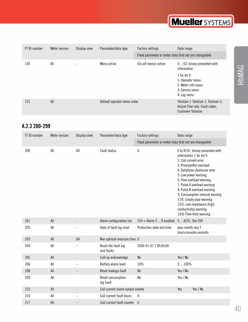
130 All - Menu active 63=all menus active 0 ... 63, binary presented with information
1 for bit 0 1: Operator menu 2: Meter info menu 3: Service menu 4: Log menu
131 All Default operator menu index Totalizer 1 Totalizer 1, Totalizer 2, Actual Flow rate, Fault codes, Customer Totalizer
FT ID number Meter version Display view Parameter/data type Factory settings Data range
Fixed parameter or meter data that not are changeable
200 All O4 Fault status 0 0 to 8191, binary presented with information 1 for bit 0 2: Coil current error 3: Preamplifier overload 4: Database checksum error 5: Low power warning 6: Flow overload warning 7: Pulse A overload warning 8: Pulse B overload warning 9: Consumption interval warning 11/E:Emptypipewarning 12/C: Low impedance (high conductivity) warning 13/d: Flow limit warning
201 All - Alarm configuration list 254 = Alarm 2 ... 8 enabled 0 ... 8191, See 200
202 All - Date of fault log reset Production date and time year-month-day T hours:minutes:seconds
203 All O4 Non optimal measure time 0
204 All - Reset the fault log 2000-01-01 T 00:00:00 and faults
205 All - Call up acknowledge No Yes / No
206 All - Battery alarm level 10% 0 ... 100%
208 All - Reset leakage fault No Yes / No
209 All Reset consumption No Yes / No log fault
215 All - Coil current alarm output enable Yes Yes / No
216 All - Coil current fault hours 0
217 All - Coil current fault counter 0
40

Hersey HbMAGElectromagnetic Flow Meters
FT ID number Meter version Display view Parameter/data type Factory settings Data range
Fixed parameter or meter data that not are changeable
218 All - Coil current fault appears 2000-01-01 T 00:00:00
219 All - Coil current fault 2000-01-01 T 00:00:00 disappears
220 All - Amplifier alarm output Yes Yes / No enable
221 All - Amplifier fault hours
222 All - Amplifier fault counter
223 All - Amplifier fault appears 2000-01-01 T 00:00:00
224 All - Amplifier fault 2000-01-01 T 00:00:00 disappears
225 All - Database alarm output Yes Yes / No enable
226 All - Database fault hours 0
227 All - Database fault counter 0
228 All - Database fault appears 2000-01-01 T 00:00:00
229 All - Database fault 2000-01-01 T 00:00:00 disappears
230 All - Low power alarm output Yes Yes / No enable
231 All - Low power fault hours 0
232 All - Low power fault counter 0
233 All - Low power fault appears 2000-01-01 T 00:00:00
234 All - Low power fault 2000-01-01 T 00:00:00 disappears
235 All - Flow overflow alarm output Yes Yes / No enable
236 All - Overflow fault hours 0
237 All - Overflow fault counter 0
238 All - Overflow fault appears 2000-01-01 T 00:00:00
239 All - Overflow fault disappears 2000-01-01 T 00:00:00
240 All - Pulse A overload alarm Yes Yes / No output enable
241 All - Pulse A overload fault 0 hours
242 All - Pulse A overload fault 0 counter
243 All - Pulse A overload fault 2000-01-01 T 00:00:00 appears
41
Hersey HbMAG
HbM
AG
FT ID number Meter version Display view Parameter/data type Factory settings Data range
Fixed parameter or meter data that not are changeable
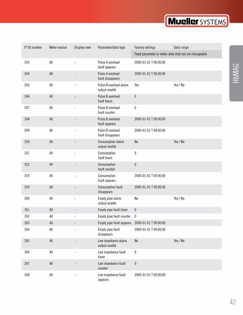
243 All - Pulse A overload 2000-01-01 T 00:00:00 fault appears
244 All - Pulse A overload 2000-01-01 T 00:00:00 fault disappears
245 All - Pulse B overload alarm Yes Yes / No output enable
246 All - Pulse B overload 0 fault hours
247 All - Pulse B overload 0 fault counter
248 All - Pulse B overload 2000-01-01 T 00:00:00 fault appears
249 All - Pulse B overload 2000-01-01 T 00:00:00 fault disappears
250 All - Consumption alarm No Yes / No output enable
251 All - Consumption 0 fault hours
252 All - Consumption 0 fault counter
253 All - Consumption 2000-01-01 T 00:00:00 fault appears
254 All - Consumption fault 2000-01-01 T 00:00:00 disappears
260 All - Emptypipealarm No Yes/No output enable
261 All - Emptypipefaulttimer 0
262 All - Emptypipefaultcounter 0
263 All - Emptypipefaultappears 2000-01-01T00:00:00
264 All - Emptypipefault 2000-01-01T00:00:00 disappears
265 All - Low impedance alarm No Yes / No output enable
266 All - Low impedance fault 0 timer
267 All - Low impedance fault 0 counter
268 All - Low impedance fault 2000-01-01 T 00:00:00 appears
42

Hersey HbMAGElectromagnetic Flow Meters
FT ID number Meter version Display view Parameter/data type Factory settings Data range
Fixed parameter or meter data that not are changeable
269 All - Low impedance fault 2000-01-01 T 00:00:00 disappears
270 All - High flow alarm No output enable
271 All - High flow alarm 0 fault timer
272 All - High flow alarm 0 fault counter
273 All - High flow alarm 2000-01-01 T 00:00:00 fault appears
274 All - High flow alarm 2000-01-01 T 00:00:00 fault disappears
FT ID number Meter version Display view Parameter/data type Factory settings Data range
Fixed parameter or meter data that not are changeable
300 All - Totalizer volume unit Product variant depended 0 ... 1*x010 factor
301 All - Flow unit factor Product variant depended 0 ... 1*x010
302 All - Pipe size Sensor-related 3”…48” (DN 80 ... 1200)
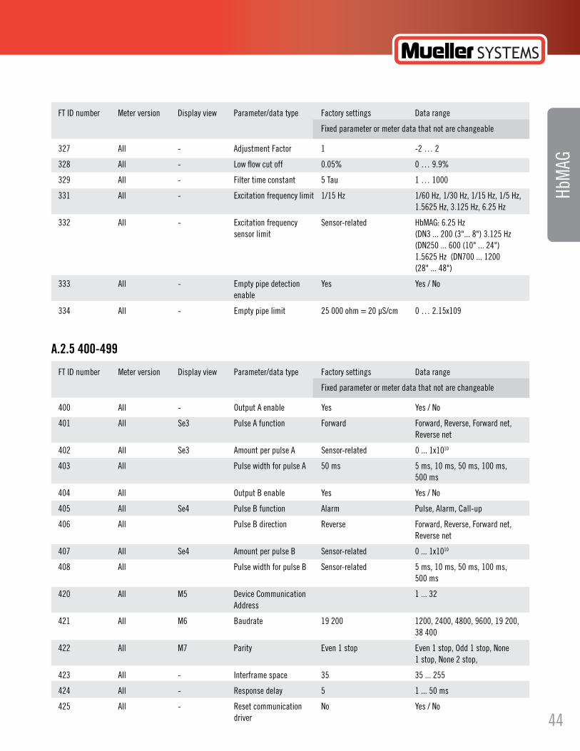
303 All - Meter excitation frequency 1/15 Hz 1/60 Hz, 1/30 Hz, 1/15 Hz, 1/5 Hz, (in battery power mode) 1.5625 Hz, 3.125 Hz, 6.25 Hz
304 All - Mains frequency Product variant depended 50 or 60 Hz mains
305 All - Decimal point Automatic point adjustment No point, One digit after point, Two digits after point, Three digits after point, Automatic point adjust
306 All - Displayed unit Product variant depended Product variant depended
310 All - Flow direction totalizer 1 Forward forward, reverse or bi-directional net flow
311 All - Totalizer 1 changes date Production date and time
312 All - Flow direction totalizer 2 Reverse forward, reverse or bi-directional net flow
313 All - Totalizer 2 changes date Production date and time
320 All - Verification mode enable No Yes / No
321 All - Calibration date Calibration date year-month-day T hours:minutes:seconds
323 All - Calibration factor Sensor-related
324 All - Gain correction Sensor-related
325 All - Sensor offset Sensor-related
A.2.4 300-399
43
Hersey HbMAG
HbM
AG
FT ID number Meter version Display view Parameter/data type Factory settings Data range
Fixed parameter or meter data that not are changeable
327 All - Adjustment Factor 1 -2 … 2
328 All - Low flow cut off 0.05% 0 … 9.9%
329 All - Filter time constant 5 Tau 1 … 1000
331 All - Excitationfrequencylimit 1/15Hz 1/60Hz,1/30Hz,1/15Hz,1/5Hz, 1.5625 Hz, 3.125 Hz, 6.25 Hz
332 All - Excitationfrequency Sensor-related HbMAG:6.25Hz sensor limit (DN3 ... 200 (3"... 8") 3.125 Hz (DN250 ... 600 (10" ... 24") 1.5625 Hz (DN700 ... 1200 (28" ... 48")
333 All - Emptypipedetection Yes Yes/No enable
334 All - Emptypipelimit 25000ohm=20µS/cm 0…2.15x10⁹
FT ID number Meter version Display view Parameter/data type Factory settings Data range
Fixed parameter or meter data that not are changeable
400 All - Output A enable Yes Yes / No
401 All Se3 Pulse A function Forward Forward, Reverse, Forward net, Reverse net
402 All Se3 Amount per pulse A Sensor-related 0 ... 1x10¹⁰
403 All Pulse width for pulse A 50 ms 5 ms, 10 ms, 50 ms, 100 ms, 500 ms
404 All Output B enable Yes Yes / No
405 All Se4 Pulse B function Alarm Pulse, Alarm, Call-up
406 All Pulse B direction Reverse Forward, Reverse, Forward net, Reverse net
407 All Se4 Amount per pulse B Sensor-related 0 ... 1x10¹⁰
408 All Pulse width for pulse B Sensor-related 5 ms, 10 ms, 50 ms, 100 ms, 500 ms
420 All M5 Device Communication 1 ... 32 Address
421 All M6 Baudrate 19 200 1200, 2400, 4800, 9600, 19 200, 38 400
422 All M7 Parity Even1stop Even1stop,Odd1stop,None 1 stop, None 2 stop,
423 All - Interframe space 35 35 ... 255
424 All - Response delay 5 1 ... 50 ms
425 All - Reset communication No Yes / No driver
A.2.5 400-499
44

Hersey HbMAGElectromagnetic Flow Meters
FT ID number Meter version Display view Parameter/data type Factory settings Data range
Fixed parameter or meter data that not are changeable
500 All - Latest service date Production date and time year-month-day T hours:minutes:seconds
501 All - Operating hours 0 hours since power-up
502 All - Battery operating time 0 hours
505 All - Power supply Power supply level Battery or mains power
506 All - Numbers of power-up Product variant depended 1 to 4 batteries
507 All - Battery power
508 All - Battery change enable No Yes / No
509 All Se1 Battery installation date Production date and time year-month-day T hours:minutes:seconds
510 All Se2 Actual battery capacity 100% 100 ... 0%
512 All - Excitationsno. 0
513 All - Power status 0 Normal operation, 1: Battery alarm. Actual battery capacity is below battery alarm level (% of max capacity)
2: Too low power (enters stand by mode)
3: As value 1 and 2 together
4:Externalpowergone
5: As value 1 and 4 together
6: As value 2 and 4 together
7: As value 1 and 2 and 4 together
514 All - Transmitter temperature Actual degree celsius
540 All - ElectrodeimpedanceA Measuredvalues 0...185000ohm
541 All - ElectrodeimpedanceB Measuredvalues 0...185000ohm
542 All - Low medium impedance 0 0 ... 2.15x10⁹ alarm
550 All - Coil current disable No Yes / No
551 All - Fixed flow mode enable No Yes / No
552 All - Fixed flow value 0 -1x10x109 ... 1x10x109
553 All - Flow alarm limit 1 000 000 000 0 ... 1x10⁹
560 All - Repair checksum No Yes / No
570 All - Device Product ID 10779
A.2.6 500-599
45

Hersey HbMAG
HbM
AG
FT ID number Meter version Display view Parameter/data type Factory settings Data range
Fixed parameter or meter data that not are changeable
600 All - Log interval Monthly Daily, Weekly (7 days), Monthly
601 All - Delay weekly log interval 0 0 ... 30
602 All - Limit for too high 1 000 000 -1x10⁹ ... 1x10⁹ consumption
603 All - Limit for too low 0 -1x10⁹ ... 1x10⁹ consumption
610 All L1 Date of latest log period 2000-01-01 T 00:00:00 year-month-day T hours:minutes:seconds
611 All L1 Latest Log period totalized (1)
612 All - Latest Log period 0 totalized (2)
613 All - Latest Log period 0 Active faults in log period; fault status 2: Coil current error 3: Preamplifier overload 4: Database checksum error 5: Low power warning 6: Flow overload warning 7: Pulse A overload warning 8: Pulse B overload warning 9: Consumption interval warning 11/E:Emptypipewarning 12/C: Low impedance/ high conductivity warning 13/d: High flow limit warning 14/15/16: Not used
614 All - Latest Log period 0 Meter operation conditions in log status information period 1: Totalizer 1 or 2 changed or reset 4: Date - time changed 5: Alarm active in logged period (See alarm fault log for same period) 6: Fault log has been reset 7: HW lock broken 8: Power Up
615 All L2 Date of log period 2
616 All L2 Log period 2 totalized (1)
617 All - Log period 2 totalized (2)
618 All - Log period 2 fault status See 613
619 All - Log period 2 status information See 614
620 All L3 Date of log period 3
621 All L3 Log period 3 totalized (1)
622 All - Log period 3 totalized (2)
A.2.7 600-799
46

Hersey HbMAGElectromagnetic Flow Meters
FT ID number Meter version Display view Parameter/data type Factory settings Data range
Fixed parameter or meter data that not are changeable
623 All - Log period 3 fault See 613 status
624 All - Log period 3 status See 614 information
625 All L4 Date of log period 4
626 All L4 Log period 4 totalized (1)
627 All - Log period 4 totalized (2)
628 All - Log period 4 fault status See 613
629 All - Log period 4 status See 614 information
630 All L5 Date of log period 5
631 All L5 Log period 5 totalized (1)
632 All - Log period 5 totalized (2)
633 All - Log period 5 fault status See 613
634 All - Log period 5 status See 614 information
635 All L6 Date of log period 6
636 All L6 Log period 6 totalized (1)
637 All - Log period 6 totalized (2)
638 All - Log period 6 fault status See 613
639 All - Log period 6 status See 614 information
640 All L7 Date of log period 7
641 All L7 Log period 7 totalized (1)
642 All - Log period 7 totalized (2)
643 All - Log period 7 fault status See 613
644 All - Log period 7 status See 614 information
645 All L8 Date of log period 8
646 All L8 Log period 8 totalized (1)
647 All - Log period 8 totalized (2)
648 All - Log period 8 fault status See 613
649 All - Log period 8 status See 614 information
650 All L9 Date of log period 9
651 All L9 Log period 9 totalized (1)
652 All - Log period 9 totalized (2)
47
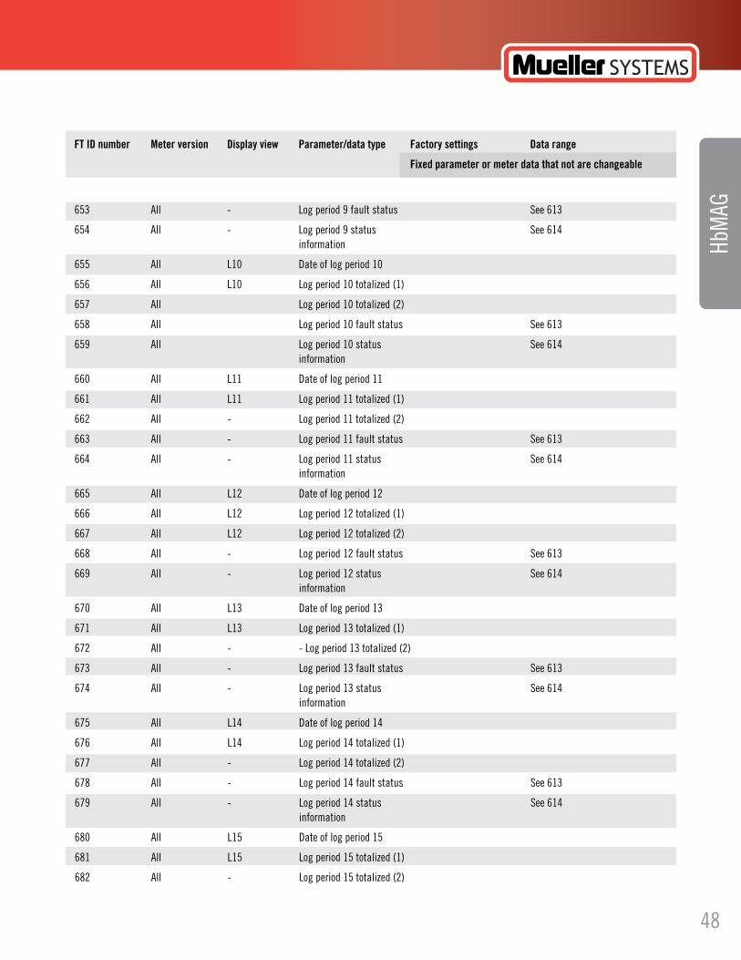
Hersey HbMAG
HbM
AG
FT ID number Meter version Display view Parameter/data type Factory settings Data range
Fixed parameter or meter data that not are changeable
653 All - Log period 9 fault status See 613
654 All - Log period 9 status See 614 information
655 All L10 Date of log period 10
656 All L10 Log period 10 totalized (1)
657 All Log period 10 totalized (2)
658 All Log period 10 fault status See 613
659 All Log period 10 status See 614 information
660 All L11 Date of log period 11
661 All L11 Log period 11 totalized (1)
662 All - Log period 11 totalized (2)
663 All - Log period 11 fault status See 613
664 All - Log period 11 status See 614 information
665 All L12 Date of log period 12
666 All L12 Log period 12 totalized (1)
667 All L12 Log period 12 totalized (2)
668 All - Log period 12 fault status See 613
669 All - Log period 12 status See 614 information
670 All L13 Date of log period 13
671 All L13 Log period 13 totalized (1)
672 All - - Log period 13 totalized (2)
673 All - Log period 13 fault status See 613
674 All - Log period 13 status See 614 information
675 All L14 Date of log period 14
676 All L14 Log period 14 totalized (1)
677 All - Log period 14 totalized (2)
678 All - Log period 14 fault status See 613
679 All - Log period 14 status See 614 information
680 All L15 Date of log period 15
681 All L15 Log period 15 totalized (1)
682 All - Log period 15 totalized (2)
48
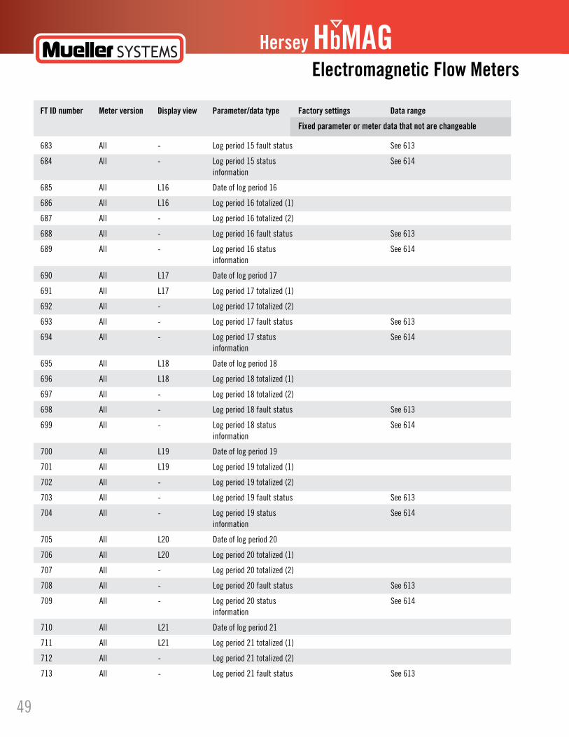
Hersey HbMAGElectromagnetic Flow Meters
FT ID number Meter version Display view Parameter/data type Factory settings Data range
Fixed parameter or meter data that not are changeable
683 All - Log period 15 fault status See 613
684 All - Log period 15 status See 614 information
685 All L16 Date of log period 16
686 All L16 Log period 16 totalized (1)
687 All - Log period 16 totalized (2)
688 All - Log period 16 fault status See 613
689 All - Log period 16 status See 614 information
690 All L17 Date of log period 17
691 All L17 Log period 17 totalized (1)
692 All - Log period 17 totalized (2)
693 All - Log period 17 fault status See 613
694 All - Log period 17 status See 614 information
695 All L18 Date of log period 18
696 All L18 Log period 18 totalized (1)
697 All - Log period 18 totalized (2)
698 All - Log period 18 fault status See 613
699 All - Log period 18 status See 614 information
700 All L19 Date of log period 19
701 All L19 Log period 19 totalized (1)
702 All - Log period 19 totalized (2)
703 All - Log period 19 fault status See 613
704 All - Log period 19 status See 614 information
705 All L20 Date of log period 20
706 All L20 Log period 20 totalized (1)
707 All - Log period 20 totalized (2)
708 All - Log period 20 fault status See 613
709 All - Log period 20 status See 614 information
710 All L21 Date of log period 21
711 All L21 Log period 21 totalized (1)
712 All - Log period 21 totalized (2)
713 All - Log period 21 fault status See 613
49

Hersey HbMAG
HbM
AG
FT ID number Meter version Display view Parameter/data type Factory settings Data range
Fixed parameter or meter data that not are changeable
714 All - Log period 21 status See 614 information
715 All L22 Date of log period 22
716 All L22 Log period 22 totalized (1)
717 All - Log period 22 totalized (2)
718 All - Log period 22 fault status See 613
719 All - Log period 22 status See 614 information
720 All L23 Date of log period 23
721 All L23 Log period 23 totalized (1)
722 All - Log period 23 totalized (2)
723 All - Log period 23 fault status See 613
724 All - Log period 23 status See 614 information
725 All L24 Date of log period 24
726 All L24 Log period 24 totalized (1)
727 All - Log period 24 totalized (2)
728 All - Log period 24 fault status See 613
729 All - Log period 24 status See 614 information
730 All L25 Date of log period 25
731 All L25 Log period 25 totalized (1)
732 All - Log period 25 totalized (2)
733 All - Log period 25 fault status See 613
734 All - Log period 25 status See 614 information
735 All L26 Date of log period 26
736 All L26 Log period 26 totalized (1)
737 All - Log period 26 totalized (2)
738 All - Log period 26 fault status See 613
739 All - Log period 26 status See 614 information
50
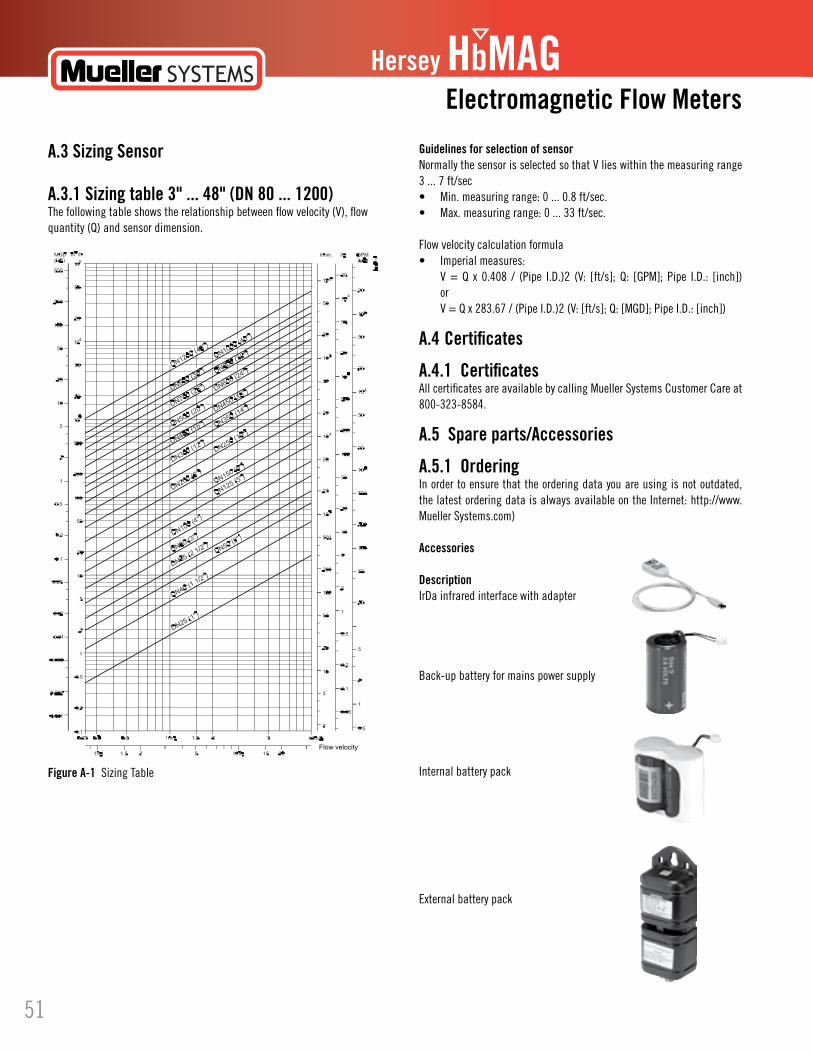
Hersey HbMAGElectromagnetic Flow Meters
Guidelines for selection of sensorNormally the sensor is selected so that V lies within the measuring range 3 ... 7 ft/sec• Min.measuringrange:0...0.8ft/sec.• Max.measuringrange:0...33ft/sec.
Flow velocity calculation formula• Imperialmeasures: V = Q x 0.408 / (Pipe I.D.)2 (V: [ft/s]; Q: [GPM]; Pipe I.D.: [inch]) or V = Q x 283.67 / (Pipe I.D.)2 (V: [ft/s]; Q: [MGD]; Pipe I.D.: [inch])
A.4 Certificates
A.4.1 CertificatesAll certificates are available by calling Mueller Systems Customer Care at 800-323-8584.
A.5 Spare parts/Accessories
A.5.1 OrderingIn order to ensure that the ordering data you are using is not outdated, the latest ordering data is always available on the Internet: http://www.Mueller Systems.com)
Accessories
DescriptionIrDa infrared interface with adapter
Back-up battery for mains power supply
Internal battery pack
Externalbatterypack
A.3 Sizing Sensor
A.3.1 Sizing table 3" ... 48" (DN 80 ... 1200)The following table shows the relationship between flow velocity (V), flow quantity (Q) and sensor dimension.
Figure A-1 Sizing Table
51
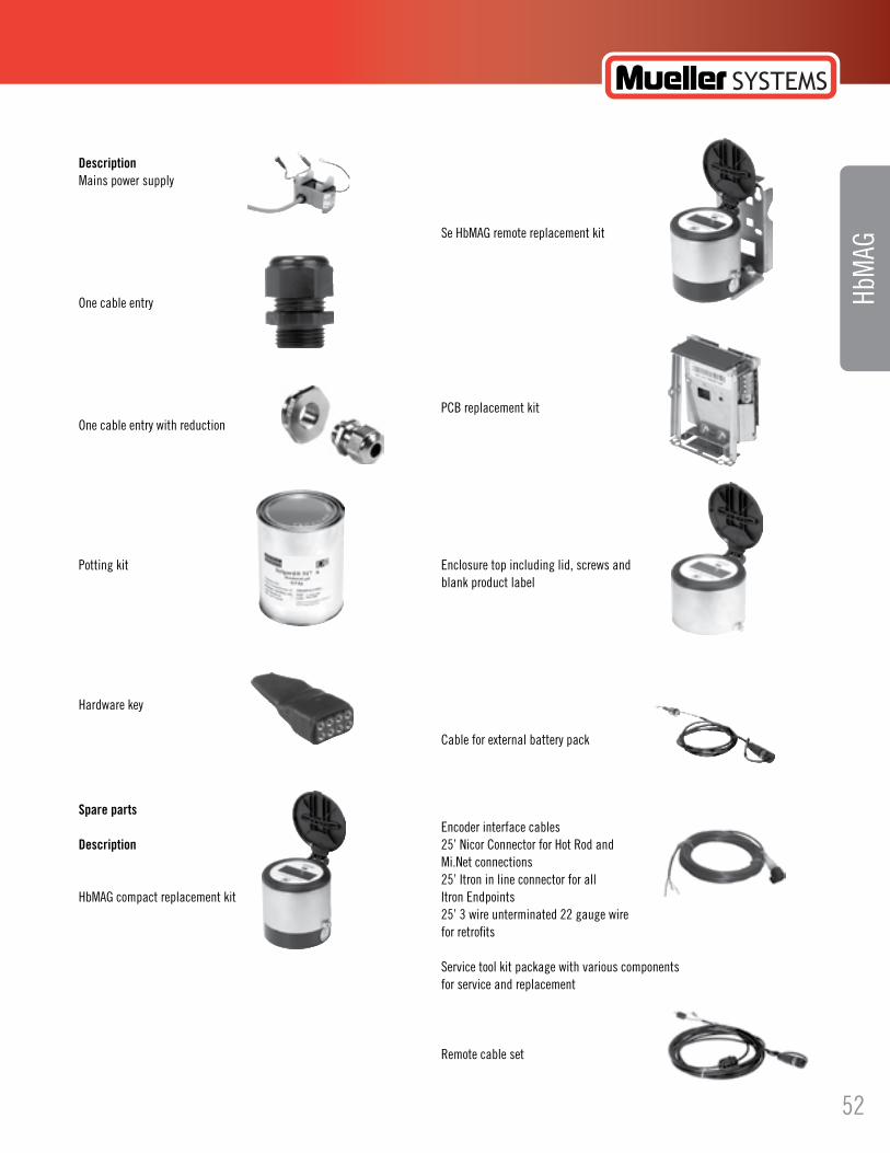
Hersey HbMAG
DescriptionMains power supply
One cable entry
One cable entry with reduction
Potting kit
Hardware key
Spare parts
Description
HbMAG compact replacement kit
Se HbMAG remote replacement kit
PCB replacement kit
Enclosuretopincludinglid,screwsand blank product label
Cable for external battery pack
Encoderinterfacecables25’NicorConnectorforHotRodand Mi.Net connections25’Itroninlineconnectorforall ItronEndpoints25’3wireunterminated22gaugewire for retrofits
Service tool kit package with various components for service and replacement
Remote cable set
HbM
AG
52
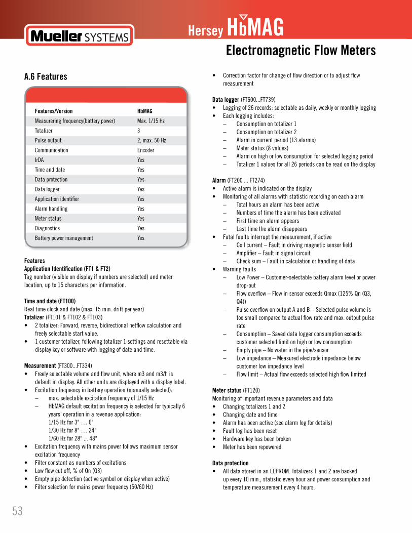
• Correctionfactorforchangeofflowdirectionortoadjustflow measurement
Data logger (FT600...FT739)• Loggingof26records:selectableasdaily,weeklyormonthlylogging• Eachloggingincludes: – Consumption on totalizer 1 – Consumption on totalizer 2 – Alarm in current period (13 alarms) – Meter status (8 values) – Alarm on high or low consumption for selected logging period – Totalizer 1 values for all 26 periods can be read on the display
Alarm (FT200 ... FT274)• Activealarmisindicatedonthedisplay• Monitoringofallalarmswithstatisticrecordingoneachalarm – Total hours an alarm has been active – Numbers of time the alarm has been activated – First time an alarm appears – Last time the alarm disappears• Fatalfaultsinterruptthemeasurement,ifactive – Coil current – Fault in driving magnetic sensor field – Amplifier – Fault in signal circuit – Check sum – Fault in calculation or handling of data• Warningfaults – Low Power – Customer-selectable battery alarm level or power drop-out – Flow overflow – Flow in sensor exceeds Qmax (125% Qn (Q3, Q4)) – Pulse overflow on output A and B – Selected pulse volume is too small compared to actual flow rate and max. output pulse rate – Consumption – Saved data logger consumption exceeds customer selected limit on high or low consumption – Emptypipe–Nowaterinthepipe/sensor – Low impedance – Measured electrode impedance below customer low impedance level – Flow limit – Actual flow exceeds selected high flow limited
Meter status (FT120)Monitoring of important revenue parameters and data• Changingtotalizers1and2• Changingdateandtime• Alarmhasbeenactive(seealarmlogfordetails)• Faultloghasbeenreset• Hardwarekeyhasbeenbroken• Meterhasbeenrepowered
Data protection• AlldatastoredinanEEPROM.Totalizers1and2arebacked up every 10 min., statistic every hour and power consumption and temperature measurement every 4 hours.
Hersey HbMAGElectromagnetic Flow Meters
A.6 Features
FeaturesApplication Identification (FT1 & FT2)Tag number (visible on display if numbers are selected) and meter location, up to 15 characters per information.
Time and date (FT100)Real time clock and date (max. 15 min. drift per year)Totalizer (FT101 & FT102 & FT103)• 2totalizer:Forward,reverse,bidirectionalnetflowcalculationand freely selectable start value.• 1customertotalizer,followingtotalizer1settingsandresettablevia display key or software with logging of date and time.
Measurement (FT300...FT334)• Freelyselectablevolumeandflowunit,wherem3andm3/his default in display. All other units are displayed with a display label.• Excitationfrequencyinbatteryoperation(manuallyselected): – max. selectable excitation frequency of 1/15 Hz – HbMAG default excitation frequency is selected for typically 6 years' operation in a revenue application: 1/15 Hz for 3" … 6" 1/30 Hz for 8" … 24" 1/60 Hz for 28" ... 48"• Excitationfrequencywithmainspowerfollowsmaximumsensor excitation frequency• Filterconstantasnumbersofexcitations• Lowflowcutoff,%ofQn(Q3) • Emptypipedetection(activesymbolondisplaywhenactive)• Filterselectionformainspowerfrequency(50/60Hz)
Features/Version HbMAG
Measurering frequency(battery power) Max. 1/15 Hz
Totalizer 3
Pulse output 2, max. 50 Hz
Communication Encoder
IrDA Yes
Time and date Yes
Data protection Yes
Data logger Yes
Application identifier Yes
Alarm handling Yes
Meter status Yes
Diagnostics Yes
Battery power management Yes
53

Hersey HbMAG
• Passwordprotectionofallparametersandhardwareprotectionof calibration and revenue parameters.
Battery power management• Optimalbatteryinformationonremainingcapacity.• Calculatedcapacityincludesallconsumingelementsandavailable battery capacity is adjusted related to change in ambient temperature.
Diagnostic• Continuousselftestincluding – Coil current to drive the magnetic field – Signal input circuit – Data calculation, handling and storing• Features – Alarm statistics and logging for fault analyzing – Electrodeimpedancetocheckactualmediacontact – Flow simulation to check pulse and communication signal chain for correct scaling – Number of sensor measurements (excitations) – Transmitter temperature (battery capacity calculation) – Low impedance alarm for change in media – Flow alarm when defined high flow exceeds – Verification mode for fast measure performance check
HbM
AG
54
Hersey HbMAGElectromagnetic Flow Meters
IndexI
AAdd-on modules Electricalconnection,13
CCommissioning With Flow Tool, 13Compliance, 2Contact person, 1Customer Support Hotline, 27
DDevice identification, 1Device inspection, 1
EEDDfiles Download, 13 Installation, 13Electricalconnection,13 Safety instructions, 9
FFlow Tool Commissioning, 13
HHistory, 1Hotline, 27
IInstallation Compact, 3 Indoor/outdoor, 3 Remote, 3Internet Contact person, 1, 27 Flowdocumentation, 1 Support, 27Introduction, 1 Items supplied, 1
LLaws and directives, 2Lithium batteries Safety, 2
MMains supply, 9Maintenance, 26Material compatibility, 2
PParameter lists, 48Pressure specifications, 3
RRepair, 27
SSafety Instrument safety standards, 2Safety instructions Electricalconnection,9Safety notes, 2Service, 27Sizing table, 57Support, 27System components, 3
TTemperature specifications, 3Type plate, 1
55