hereby allow my thesis to be placed at the information ...utpedia.utp.edu.my/9265/1/2009 -design of...
TRANSCRIPT
STATUS OF THESIS
Title of thesisDesign of Contraflow Cleaning PIG for Pipeline Maintenance
I KRESNAJAYA PRASETIA PANCAKARSA
hereby allow my thesis to be placed at the Information Resource Center (IRC) of
Universiti Teknologi PETRONAS (UTP) with the following conditions:
1. The thesis becomes the property of UTP.
2. The IRC of UTP may copies of the thesis for academic purposes only.
3. This thesis is classified as
Confidential
v Non-confidential
If this thesis is confidential, please state the reason:
The content of the thesis will remain confidential for
Remarks on disclosure:
years.
Endorsed by
KRESNAJAYA PRASETIA
PANCAKARSA
Puncak SekuningNo. 43/789,
Palembang, Sumatera Selatan, Indonesia
Date: 16th March, 2009
FAKHRULDIN MOHD HASHIM
Universiti Teknologi PETRONAS
Malaysia
Date: 16th March, 2009
UNIVERSITI TEKNOLOGI PETRONASApproval by Supervisor (s)
sTrtSi§ned C£rtify ^,h6y^ ^ ^ r—* t0 ** »**•*»*smdtes Pr for acceptancej athesjs entMed lJImss^^^f*^*^^^ fitted b^~i^-**«for the fulgent of the requirements for the^f^rTfScience in Mechanical Engineering.
rth16 March. 700Q
Date
Signature
Main Supervisor
Date
Co-Supervisor
A. P. Dr. Fakhruldir, Mnh* Hashim
rth16rn March, 2009
n
TITLE PAGE
UNIVERSITI TEKNOLOGI PETRONAS
Design of Contraflow Cleaning PIG for Pipeline Maintenance
By
Kresnajaya Prasetia Pancakarsa
A THESIS
SUBMITTED TO THE POSTGRADUATE STUDIES PROGRAMME
AS A REQUIREMENT FOR THE
DEGREE OF MASTER OF SCIENCE
MECHANICAL ENGINEERING
BANDAR SERIISKANDAR,
PERAK,
MARCH, 2009
in

DECLARATION
I hereby declare that the thesis is based on my original work except for quotations and
citations which have been duly acknowledged. I also declare that it has not been
previously or concurrently submitted for any other degree at UTP or other institutions.
Signature :
Name KRESNAJAYA PRASETIA PANCAKARSA
Date : 16th March, 2009
IV

ACKNOWLEDGEMENT
I would first like to acknowledge my supervisor A.P. Dr. Fakhruldin Mohd Hashim,
for his help and guidance given in the supervision of this researchwork.
I would like to special thanks to my parents for supporting me through the years of
my postgraduate study and encouraging me to pursue my dream. To my brothers who
have helped me to believe the path that I should do. I am also grateful to my best
friends Wiwiek for valuable discussions and memorable moments we spent together. I
would like to thank to Dani, Hendra, Arif, Ariyanti, Firman and Rivai for their help
and valuable advice.
I would like also to thank to Mechanical Engineering Department, Universiti
Teknologi PETRONAS, for the use of related equipment and facilities, personnel
support and assistance.
Finally, acknowledgment is also given to Universiti Teknologi PETRONAS for the
generous funding that ledto thesuccessful completion of the research.
ABSTRACT
Conventional Pipeline Inspection Gauge (PIG) is a device used to remove solid
deposit from the pipeline wall and driven by the fluid flow. For single offshore
pipeline application, it needs to be launched from the manifold at the seabed which
has drawbacks on the water depth restriction and requires intervention from the
surface to launch the PIG. The current trend on the PIG design to overcome this
challenge is to develop a counter flow PIG for single offshore pipeline application
which is unequipped with the PIG launcher at the manifold.
Two of the commercial counter flow prototypes are contraflow tetherless mechanical
crawler developed by the Astec Development Ltd. which has a drawback of poor
traveling speed and Durham Pipeline Technology (DPT) crawler developed by
University of Durham which has a drawback of discontinuedmotion. In this research,
it is focused on the generation of a model of PIG with the function of wax removal.
The requirement of the PIG design includes the ability to travel in both forward and
reverse direction at a constant speed. In order to come out with the expected results,
the scope of the research work is limited to the generation of the conceptual design of
the PIG, product architecture and configuration design defined of the proposed
concept and generation of Computational Aided Design (CAD) model of the proposed
concept.
A systematic design based on Dieter's approach is adopted to design a PIG. It consists
of conceptual and embodiment phases. In the conceptual design phase, the PIG design
starts with problem definition, generating number of possible concepts using
functional decomposition method and selecting the most promising concept using
conceptscreening method. The most promising concept of PIG design consists of five
modules, specifically: drive mechanism, turbine for drive mechanism, flow control,
turbine for wax removal and wax removal module. Furthermore, a layout and
configuration of critical components of the most promising concept is performed in
the embodiment phase.
The PIG is designed with reference to the product design specification document of
VI
the pipeline operating condition ofpressure of 15 MPa, fluid velocity of 1 m/s and apressure drop across the PIG of 31 kPa. The PIG design begins with the analysis of
the impeller to determine the maximum power that can be generated from the fluidflow. The turbine module has a function to provide power to drive the drive
mechanism and the wax removal module. Dimension of the impeller that can generate
maximum power is calculated based on the meridional and cascade flow analysis.
Furthermore, to ensure the valid assumption of the design parameter that is used to
determine the dimension of the impeller, a CAD model of impeller is simulated using
the Fluent software.
In order to travel in a constant speed, the turbine for drive mechanism module is
attached with flow control module which uses a perpetual mechanism of a poppet
valve and a spring in the crawling mode and a magnetic mechanism in the return
mechanism. For the drive mechanism device, a cam follower with bristle is used in
the PIG design. The calculation of the cam follower mechanism follows the bristle
theory that has been developed by Stutchbury. For wax removal, a cutting tool is used
in the PIG design where the design of the cutting tool refers to the cutting tool
standard used for machining process.
Based on the preliminary analysis, the PIG design can move in a counter flow at
speed of 0.03 m/s with the time ratio between the PIG movements in forward
direction and stationary condition of 4.28. The PIG design can remove wax solid
deposit with a maximum shear strength of 81 kPa. The outcome of this research is an
assembly drawing of the PIG design.
vn
ABSTRAK
Pipeline Inspection Gauge (PIG) konvesional merupakan alat digerakkan oleh aliran
cecair untuk mengasingkan sisa pepejal daripada sistem paip. Untuk aplikasi sistem
paip pesisir pantai, alat ini perlu dilancarkan bermula dari manifold di dasar laut yang
bergantung kepada kedalaman laut dan memerlukan perantaraan daripada permukaan
laut untuk melancarkannya. Rekaan terkini PIG untuk mengatasi masalah ini ialah
membangunkan aliran balas PIG untuk aplikasi sistem paip pesisir pantai yang tidak
dilengkapi dengan pelancar PIG pada manifold.
Dua prototaip aliran balas komersial iaitu contraflow tetherless mechanical crawler
yang dibangunkan oleh Astec Development Ltd. mempunyai kelemahan pada
kelajuan rendah manakala Durham Pipeline Technology (DPT) crawler pula
dibangunkan oleh Universiti Durham mempunyai kelemahan gerakan tidak tetap.
Kajian ini memfokuskan penghasil model PIG dengan fungsi penyahbuangan wax.
Rekaan PIG ini berkebolehan untuk bergerak ke depan dan mengundur dengan
kelajuan sekata. Skope kajian ini dihadkan kepada penghasilan rekaan konsep PIG,
arkitektur produk dan rekaan konfigurasi yang menekankan kepada cadangan konsep
dan penghasilan model Computer Aided Design (CAD).
Rekaan PIG ini diadaptasi daripada pendekatan rekaan Dieter. Rekaan ini
merangkumi dua fasa iaitu konsep dan implimentasi. Fasa rekaan konsep, rekaan PIG
ini bermula dengan definisi masalah, kemudian penghasilan beberapa konsep
penyelesaian masalah menggunakan kaedah functional decomposition. Pemilihan
konsep yang paling menyerlah dilakukan menggunakan kaedah penyaringan. Konsep
PIG ini merangkumi lima modul iaitu mekanisme pacuan, turbin untuk mekanisma
pacuan, kawalan aliran, turbin untuk penyahbuangan wax dan sistem penyahbuangan
wax. Susunan dan konfigurasi, komponen kritikal dalam konsep yang paling
menyerlah dilakukan dalam fasa implimentasi.
PIG ini direka berdasarkan spesifikasi rekaan sistem paip yang beroperasi
menggunakan tekanan 15 MPa, kelajuan aliran sebanyak 1 m/s dan tekanan turun
sepanjang PIG sebanyak 31 kPa. Rekaan PIG ini bermula dengan analisis impeller
vin
untuk menentukan kuasa terkuat yang boleh dihasilkan oleh aliran cecair. Modul
turbin berfungsi untuk menyediakan kuasa untuk memacu mekanisma pacuan dan
penyahbuangan wax. Dimensi impeller untuk menghasilkan kuasa terkuat dikira
berdasarkan meridional dan cascade analisis cecair. Selain itu, parameter rekaan yang
digunakan untuk menentukan dimensi impeller adalah berdasarkan pensian Fluent.
Turbin untuk mekanisme pacuan dipasang bersama kawalan aliran modul untuk
memastikan kelajuan sekata yang menggunakan mekanisme perpetual injap poppet
bersama spring di dalam modul crawling dan mekanisme magnetic dalam mekanisme
pembalikan. Untuk alat mekanisme pacuan, cam follower dengan bristle digunakan
untuk rekaan PIG. Pengiraan mekanisme camfollower berdasarkan teori bristle yang
dibangunkan oleh Stutchbury. Penyahbuangan wax, alat pemotong digunakan
berdasarkan standard yang digunakan dalam proses mesin.
Berdasarkan analysis awal, rekaan PIG boleh digunakan dalam aliran balas dengan
kelajuan 0.03 m/s dengan nisbah masa antara pergerakan PIG ke depan dan keadaan
statik sebanyak 4.28. Rekaan PIG juga menyahbuang sisa wax dengan kekuatan
maximum 81 kPa. Hasil daripada kajian ini ialah lukisan penuh rekaan PIG.
IX
TABLE OF CONTENTS
STATUS OF THESIS i
DECLARATION iv
ACKNOWLEDGEMENT v
ABSTRACT vi
ABSTRAK viii
TABLE OF CONTENTS x
LIST OF TABLES xiii
LIST OF FIGURES xiv
ABBREVIATION xvii
NOMENCLATURE xviii
CHAPTER ONE: INTRODUCTION 1
1.1 Introduction 1
1.2 Problem Statement 4
1.3 Objective of the Study 4
1.4 Scope of Works 5
1.5 Methodology 5
1.6 Organization of Thesis 6
CHAPTER TWO: CONVENTIONAL PIG 8
2.1 Introduction 8
2.2 Offshore Pipeline Problem 8
2.2.1 Wax 9
2.2.2 Asphaltene 9
2.2.3 Hydrate 9
2.3 Method to Prevent Solid Deposit 10
2.4 PIG 11
2.4.1 PIG Definition 11
2.4.2 PIG Classification 12
2.5 Utility PIG 12
2.5.1 Utility PIG Classification 12
x
2.5.2 Pigging Operation Procedure 14
2.5.3 Wax Removal Mechanism 16
2.5.4 Drawback of Utility PIG 17
2.6 Intelligent PIG 19
CHAPTER THREE: CONTRAFLOW PIG 20
3.1 PIG Design Development for Unpiggable Pipeline 20
3.2 Challenges in the PIG Development for Subsea Pipeline 27
3.3 State of the Art of Counter Flow PIG 29
3.3.1 Contraflow Tetherless Pipeline Crawler 30
3.3.2 DPT Crawler 34
3.4 Some Others Concept Model of Contraflow PIG 37
3.4.1 Pipeline PIG 37
3.4.2 Autonomous Robotic Crawler for In-pipe Inspection 41
3.5 Customer Need of PIG Design 42
CHAPTER FOUR: METHODOLOGY 44
4.1 Overall Methodology 44
4.1.1 Conceptual Design Phase 45
4.1.1.1 Problem Definition Step 45
4.1.1.2 Gathering Information Step 45
4.1.1.3 Concept Generation Step 45
4.1.1.4 Concept Evaluation Step 46
4.1.2 Embodiment Design Phase 46
4.1.2.1 Product Architecture 46
4.1.2.2 Configuration Design 47
4.1.3 CAD Model 47
4.2 Tools 47
CHAPTER FIVE: RESULT AND DISCUSSION 48
5.1 Introduction 48
5.2 Conceptual Design 48
5.2.1 Problem Definition 48
XI
5.2.2 Gathering Information 52
5.2.3 Concept Generation 54
5.2.4 Concept Evaluation 70
5.3 Embodiment Design Phase 73
5.3.1 Product Architecture 73
5.3.2 Configuration Design 75
5.3.2.1 Overall Flowchart Design 76
5.3.2.2 Turbine Module 78
5.3.2.3 Flow Control Module 93
5.3.2.4 Drive Mechanism Module 99
5.3.2.5 Wax Removal Tool Module 120
5.3.3 Assembly of the PIG Design 124
5.3.4 Capabilities 130
5.3.5 Limitation 131
5.3.6 The Difference with Contraflow Tetherless Mechanical Pipeline 131
Crawler DPT Crawler
CHAPTER SIX: CONCLUSION AND RECOMMENDATIONS 132
6.1 Introduction 132
6.2 Conclusion 132
6.3 Recommendations 133
REFERENCES 134
APPENDIX A: EXAMPLE OF CONCEPTUAL EVALUATION FORM 138
OF CONTRAFLOW PIG DESIGN FOR PIPELINE MAINTENANCE
APPENDIX B: TECHNICAL DRAWING OF PIG DESIGN 146
xn
LIST OF TABLES
Table 3-1: Design parameter of DPT crawler. 37
Table 5-1: Benchmarking of past and current PIG design. 50
Table 5-2: PDS of PIG design. 52
Table 5-3: Function from each subassemblies of the contraflow tetherless 54
mechanical pipeline crawler.
Table 5-4: Typical mechanical design function. 56
Table 5-5: Morphological chart of PIG design. 60
Table 5-6: Several new PIG concepts. 66
Table 5-7: Score-rank table of PIG selection survey. 72
Table 5-8: PIG design operating condition. 76
Table 5-9: The requirement of turbine design. 80
Table 5-10: Dimensional analysis of turbine design. 81
Table 5-11: Force and torque acting on the impeller element based on 86
meridional analysis.
Table 5-12: Fluid angle (p) and relativevelocity (W) at a particular element. 89
Table 5-13: Force and torque acted on elements of impeller turbine based on 90
cascade analysis.
Table 5-14: The torque act on the impeller based on simulation. 92
Table 5-15: Pressure drop across the flow control module and force acting on 96
the poppet valve.
Table 5-16: The attractive force exerted to the end inner case by magnet. 98
Table 5-17: Assumption of design parameter for drive mechanism module. 108
Table 5-18: Force acting on the PIG design when moving in the counter flow 109
direction.
Table 5-19: Bristle force analysis on drive mechanism module. 112
Table 5-20: Calculation result of force balance equation when PIG moving in 114
the counter flow direction.
Table 5-21: Calculation result of force balance equation when nut moving. 116
Table 5-22: Specification of the turbine module. 121
Table 5-23: Hardness of material. 123
Table 5-24: Element of the cutting tool of HSS for cutting brass. 124
xin
LIST OF FIGURES
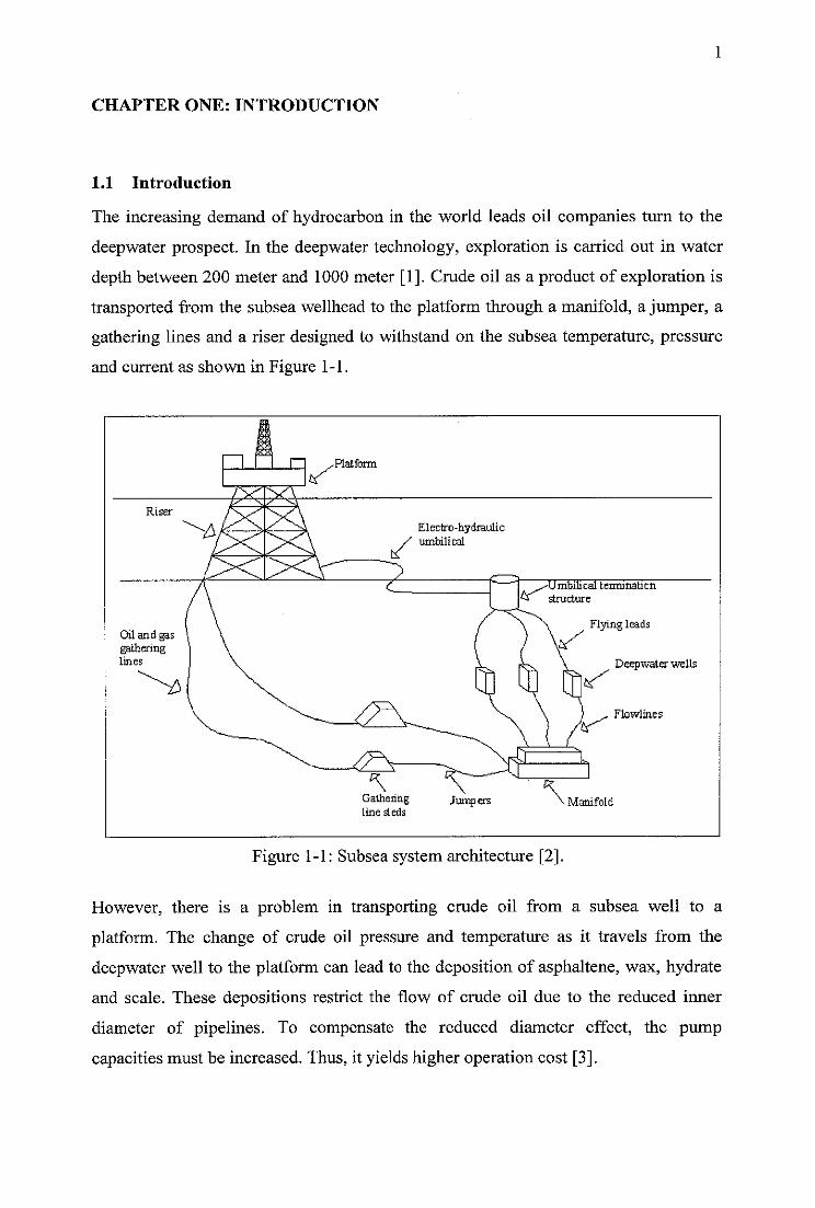
Figure 1-1: Subsea system architecture. 1
Figure 1-2: Overall methodology of PIG design. 5
Figure 2-1: Oil phase diagram from deepwater field in Gulf of Mexico. 8
Figure 2-2: Type of utility PIG. 13
Figure 2-3: Cleaning element 14
Figure 2-4: A typical configuration of a pig launcher for liquid service. 15
Figure 2-5: Working principle of utility PIG. 15
Figure 2-6: Force acting on the PIG. 16
Figure 2-7: Typical force generated by utility PIG versus the distance 17
behavior.
Figure 2-8: Construction HAAP™ 18
Figure 3-1: Roboscan inspection robot for unpiggable pipelines. 21
Figure 3-2: Detailed of Roboscan module. 22
Figure 3-3: Multidiameter PIG for unpiggable pipeline. 23
Figure 3-4: Asgard transport system. 24
Figure 3-5: ICC Autonomous PIG for unpiggable pipeline. 26
Figure 3-6: Ideal pigging operation. 27
Figure 3-7: Subsea pipeline configuration. 28
Figure 3-8: Contraflow tetherless pipeline crawler. 30
Figure 3-9: Tractor module of contraflow tetherless mechanical crawler. 31
Figure 3-10: Working principle of tractor module. 32
Figure 3-11: Return module. 33
Figure 3-12: DPT crawler. 34
Figure 3-13: Working principle of the DPT crawler. 35
Figure 3-14: DPT PIG motion. 37
Figure 3-15: Pipeline PIG. 38
Figure 3-16: Detail each module ofpipeline PIG. 39
Figure 3-17: Working principle of pipeline PIG. 40
Figure 3-18: Autonomous robotic crawler. 41
Figure 4-1: Overall methodology of PIG design. 44
Figure 5-1: Physical decomposition of the contraflow tetherless mechanical 53
xiv
pipeline crawler.
Figure 5-2: Overall function of PIG design. 56
Figure 5-3: Detail function of PIG design. 57
Figure 5-4: Classification of drive mechanism. 62
Figure 5-5: The proposed PIGconcept. 72
Figure 5-6: Schematic diagram of PIG design. 74
Figure 5-7: Product architecture of PIG design. 74
Figure 5-8: A rough layout of PIG design. 75
Figure 5-9: Overall flowchart of PIG design. 77
Figure 5-10: Working principle of the turbine module. 78
Figure 5-11: Design flowchart to determine power generated by the turbine 79
module.
Figure 5-12: Treatment of three dimensional flows through axial turbine as 82
superposition ofmeridional and cascade flow.
Figure 5-13: Transformation of a cylindrical cascade section into an infinite 82
rectilinear cascade in the (x,y) plane.
Figure 5-14: Axial turbine. 85
Figure 5-15: Airfoil section of axial impeller turbine. 87
Figure 5-16: Impeller profile. 87
Figure 5-17: Characteristic of aerofoil NACA 2409. 89
Figure 5-18: Boundary condition of turbine design simulation. 91
Figure 5-19: Result from the simulation in Fluent. 92
Figure 5-20: Characteristic of turbine design. 93
Figure 5-21: Schematic of a flow control module. 94
Figure 5-22: Design flowchart of the flow control module. - 94
Figure 5-23: Schematic of flow control module during return mode. 97
Figure 5-24: Ring shaped magnet. 98
Figure 5-25: A unique characteristic of the bristle. 99
Figure 5-26: Buckling of an Euler column. 101
Figure 5-27: The forces acted on the PIG design. 103
Figure 5-28: Free body diagram of a drive mechanism.. 104
Figure 5-29: Forces acting on the double screw thread. 104
Figure 5-30: Flow chart ofdrive mechanism module. 107
xv
Figure 5-31: Free body diagram of drive mechanism when the PIG design is 109
in a stationary stage.
Figure 5-32: Overall PIG design speed through the time. 118
Figure 5-33: Rotational speed of drive mechanism through the time. 119
Figure 5-34: Wax removal mechanism. 120
Figure 5-35: Design flowchart of a solid deposit removal tool. 120
Figure 5-36: Force acted on the cutting tool and wax deposit. 121
Figure 5-37: Free body diagram of the cutting tool. 122
Figure 5-38: Element of the cutting tool. 124
Figure 5-39: Assembly drawing of the PIG design. 125
Figure 5-40: Assembly drawing of the wax removal module. 126
Figure 5-41: Assembly drawing of the turbine for wax removal module. 127
Figure 5-42: Assembly drawing of the flow control module. 128
Figure 5-43: Assembly drawing of the turbine for drive mechanism module. 129
Figure 5-44: Assembly drawing of the drive mechanism module. 130
xvi
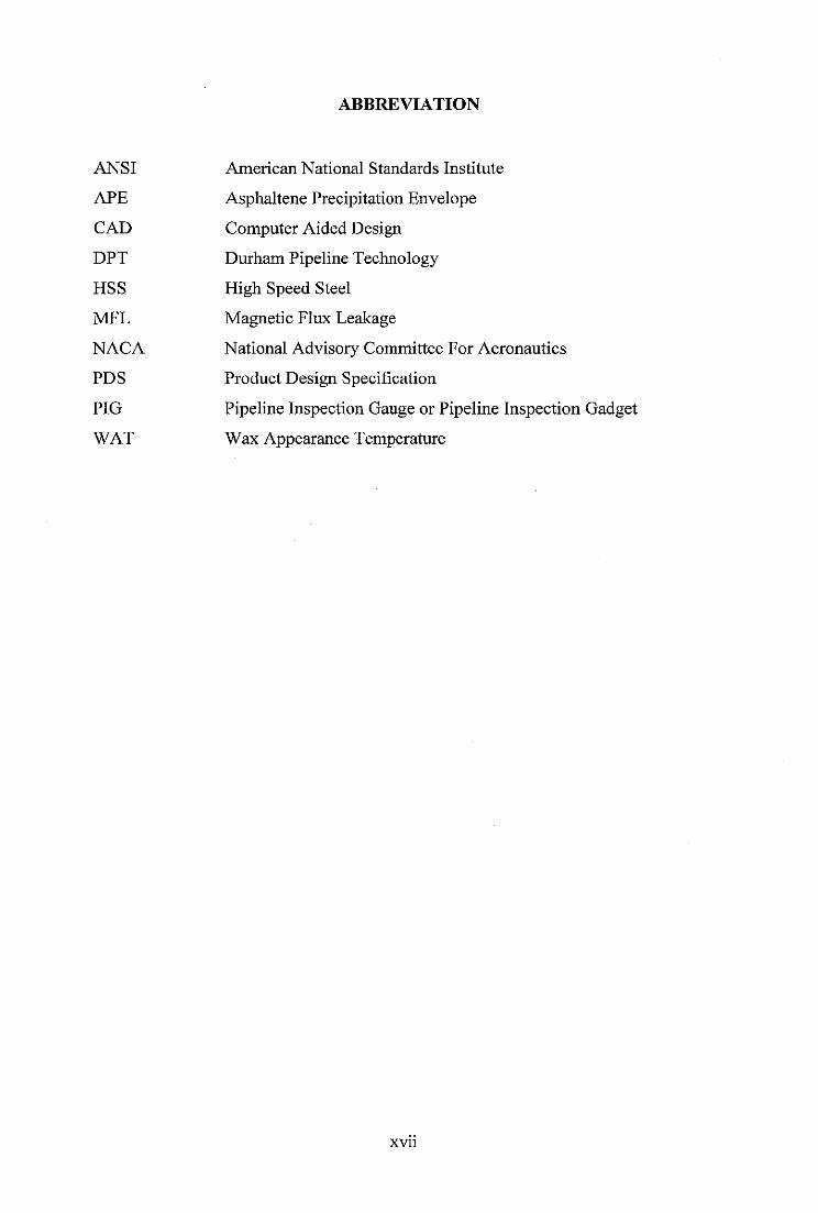
ABBREVIATION
ANSI American National Standards Institute
APE Asphaltene Precipitation Envelope
CAD Computer Aided Design
DPT Durham Pipeline Technology
HSS High Speed Steel
MFL Magnetic Flux Leakage
NACA National Advisory Committee For Aeronautics
PDS Product Design Specification
PIG Pipeline Inspection Gauge or Pipeline Inspection Gadget
WAT Wax Appearance Temperature
xvu
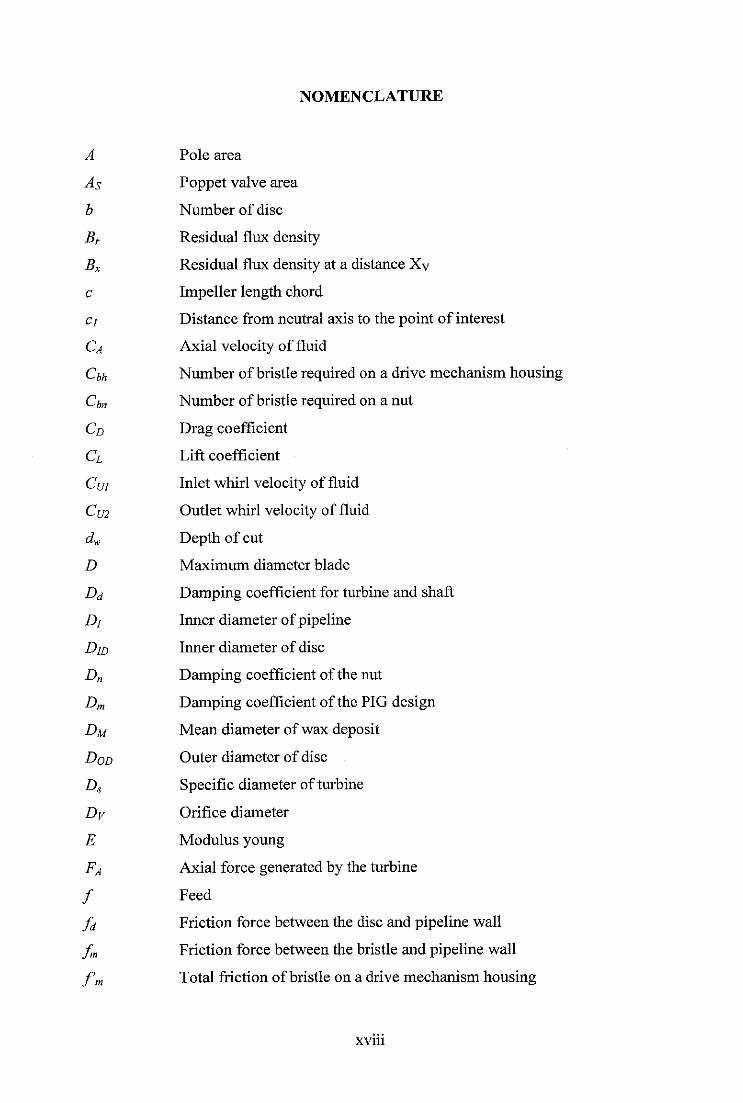
NOMENCLATURE
A Pole area
As Poppet valve area
b Number of disc
Br Residual flux density
Bx Residual flux density at a distance Xy
c Impeller length chord
a Distance from neutral axis to the point of interest
Ca Axial velocity of fluid
Cbh Number of bristle required on a drive mechanism housing
Cbn Number of bristle required on a nut
Co Drag coefficient
d Lift coefficient
Cui Inlet whirl velocity of fluid
Cm Outlet whirl velocity of fluid
dw Depth of cut
D Maximum diameter blade
Dd Damping coefficient for turbine and shaft
Dj Inner diameter ofpipeline
Dm Inner diameter of disc
Dn Damping coefficient of the nut
Dm Damping coefficient of the PIG design
Dm Mean diameter of wax deposit
Dod Outer diameter of disc
Ds Specific diameter of turbine
Dy Orifice diameter
E Modulus young
FA Axial force generated by the turbine
/ Feed
ft Friction force between the disc and pipeline wall
fm Friction force between the bristle and pipeline wall
f'm Total friction of bristle on a drive mechanism housing
xvm
fn Friction force of the nut against the pipe
/'„ Total friction of bristle on nut in reverse direction
Fam Attractive force exerted by a magnet to a ferromagnetic material
Fb Frictional force between PIG and pipeline wall
Fb Reaction force generated by the nut
(Fb)p Reaction force on the thread
Fc Maximum cutting force
Fp Propulsion force generated by the thread when nut moving forward
(Fp)p Propulsion force generated by the thread when PIG moving forward
Fs Breaking force of wax
Fs Force acting on a poppet valve due to the pressure difference
Ft Total force generated by the utility PIG
(Ft)e Axial force on the certain element of impeller
Fap Propulsion force from the pressure drop across the poppet valve
Fws Frictional force between the wax plug and wax deposit surface
h Length of bristle
H Head
/ Moment inertia
Id Moment inertia of turbine and shaft
K Mode of Euler buckling theory
Ks Spring stiffness
/ Pitch of the screw
L Length of screw
LM Magnetic length
Ls Free length of spring
mm Mass of the PIG design
mn Mass of the nut
rim Ratio reduction of harmonic gear
M Bending moment
N Number of impeller
Nd Normal reaction force on the PIG disc
Ns Specific speed of turbine
OD Outside diameter of spring
xix
Pi Inlet pressure
P2 Outlet pressure
Pcr Critical compression length
Pt Power generated by the turbine
Q Volume flow rate
r Radius from turbine axis to a certain element of impeller
rb Radius of bristle
rd Radius of shaft
ru Inner radius of ring shaped magnet
Rm Outer radius of ring shaped magnet
Rh Hub diameter of impeller
Rp Resultant force in forward direction
Rpf Ration of traction force to push bristle in reverse and forward direction
Rp Tip diameter of impeller
Rh/Rt Hub to tip diameter ratio
R 'a Axial thrust in reverse direction
R 'p Resultant force in reverse direction
tm Time of the PIG design to travel in one cycle motion
t„ Time of nut travel along the entire length of double screw
T Total torque acting on the impeller
Tb Reaction torque generated by the nut
(Tb)p Reaction torque generated by the thread
(T)e Torque acting on the certain element of impeller
TV Torque required by the drive mechanism module when nut moving
forward
(Tf)p Torque required by the drive mechanism module when PIG moving
forward
U Impeller speed at certain radius
Ur Disc oversize to the pipeline diameter
Vf Fluid velocity
v„ Velocity of the nut
vp Velocity ofthe PIG design
W Relative velocity of velocity
xx
Wi Relative velocity at the inlet
W2 Relative velocity at the outlet
Xy Compression length of poppet valve
pi Inlet fluid angle
J32 Outlet fluid angle
pM Mean fluid angle
p Crude oil density
•n Hydraulic efficiency
jU.Rm Friction force in forward direction
/U.R'n Friction force in reverse direction
f^sl Slidingfrictionbetweenthe disc and pipeline
ps2 Friction coefficient between bristle and pipeline
(p Friction angle perpendicular to the normal reaction force
co Rotational speed of turbine
cOsV Rotational speed of wax deposit removal shaft
codm Rotational speed of drive mechanism when nut moving forward
(g)dm)p Rotational speedof drivemechanism when PIG moving forward
cow Rotational speed of wax removal tool
y Bristle tip angle
APt Pressure drop across the PIG
Az Width of each impeller
xxi
CHAPTER ONE: INTRODUCTION
1.1 Introduction
The increasing demand of hydrocarbon in the world leads oil companies turn to the
deepwater prospect. In the deepwater technology, exploration is carried out in water
depth between 200 meter and 1000 meter [1]. Crude oil as a product of exploration is
transported from the subsea wellhead to the platform through a mamfold, a jumper, a
gathering lines and a riser designed to withstand on the subsea temperature, pressure
and current as shown in Figure 1-1.
Figure 1-1: Subsea system architecture [2].
However, there is a problem in transporting crude oil from a subsea well to a
platform. The change of crude oil pressure and temperature as it travels from the
deepwater well to the platform can lead to the deposition of asphaltene, wax, hydrate
and scale. These depositions restrict the flow of crude oil due to the reduced inner
diameter of pipelines. To compensate the reduced diameter effect, the pump
capacities must be increased. Thus, it yields higher operation cost [3].
There are several methods that have been developed by oil companies to limit the
deposit formation, i.e. chemical treatment, pipeline insulation, and pigging. For large
subsea pipelines, the use of chemical treatments such as solvent and dispersant to
mitigate the solid deposit especially wax is generally not practical [4]. Solvent for
solid deposit removal must be concentrated and given sufficient contact time to be
effectively worked. This can be done by continuously injecting solvent to the pipeline
which increases the maintenance cost. Another method is by insulating or heating the
pipeline to maintain the temperature of crude oil in the range where the deposit cannot
be formed. However, applying insulation or heating methods to the existing subsea
pipeline requires high cost [4]. The most common way used by the oil companies to
control this deposit is by running regular pigging program.
A utility or a cleaning PIG (Pipeline Inspection Gauge) is inserted into subsea
pipelines by pressuring the PIG launcher. Then, fluid flow drives the PIG to travel
through the entire length of the pipelines. At the end of the pipelines, there is a PIG
receiver to retrieve the PIG. The utility PIG removes solid deposit by physically
scraping solid deposit from the pipelines wall and pushes it to the end of the pipelines.
The drawbacks of utility PIG are [3]:
a. The cleaning force used to remove solid deposit is not actively generated.
Instead, it is a result of scraping effect between the pipeline inner wall and the
PIG cleaning element. Therefore, the efficiency of deposit removal depends on
the PIG velocity and the hardness of cleaning element. Normally, the PIG travel
at speed about 1 to 5 m/s for liquid pipelines and 2 to 7 m/s for gas pipelines [5].
This requirement often can not be fulfilled by the normal operation flow from the
well which results the need of a large pumping system.
b. The utility PIG is at the risk of becoming stuck due to the heavy block of
accumulation wax removal. Typically, the utility PIG remove the solid deposit
by pushing it and the wax removal will accumulate in front of the PIG. In case
where the PIG diameter is not correct chosen or the different prediction of solid
deposit thickness, the PIG may get stuck inside the pipeline. In order to retrieve
it, the pipeline operation needs to be adapted or interrupted. It means that the oil
companies loss their production during the pigging operation.
c. The removed deposit is accumulated in front of the PIG and being pushed out of
the pipeline as the PIG moving forward.
d. The utility PIG uses the fluid flow as a main propulsion source. Typically, it is
not equipped with the driving main mechanism. As a consequence, it can move
only in the same direction with the fluid flow.
A pipeline is designed based on the standard to allow a utility PIG to travel through
the entire length of the pipelines. To be piggable, the pipeline should be more or less
constant bore, sufficiently long radius bend, and equipped with the traps to launch and
receive PIG [6]. However, it is commonly found that the pipeline is unpiggable due to
over or under-sized valve, repair section in a different size, a short bend or
unavailable traps.
In some subsea system like in Northern Sector of North Sea Shell Expro, the pipeline
that are used for transporting crude oil from a well into a platform are single lines
which is not equipped with a PIG launcher at the seabed [7]. The unavailability of
PIG facility makes these pipelines are unpiggable. To use a utility PIG in doing
pigging to this subsea system, it creates dilemma either to create extra pipelines to
make a pigging loop system or to install the PIG launcher at the seabed which
requires periodic and expensive intervention from a surface supported system.
One of the challenges in the PIG development in the next 10-20 years is to develop a
PIG that can be deployed from the surface and uninterrupted the production [8]. PIG
companies have developed counter flow PIG types as a solution for these challenges.
The counter flow PIG has a feature of drive mechanism which makes it able to travel
in a counter flow direction. It operates in the pipeline without tether and generates its
own power by converting fluid flow into rotational energy. The use of fluid flow as a
power source to drive a drive mechanism makes the counter flow PIG able to travel
through the entire length of the pipeline. If the counter flow PIG faced an obstruction
or reached at the end of the pipeline, it would automatically return to the initial point
of launching. The benefits of counter flow PIG are uninterrupted production during
pigging operation, reducing risk of the PIG being stuck inside a pipeline, and cost
saving on the PIG facilities.
Currently, there are two types of counter-flow PIG prototypes that have been
developed, specifically: contraflow tetherless pipeline crawler and DPT crawler. The
contraflow tetherless pipeline crawler had been developed by Astec Development
Ltd., which was later acquired by the Weatherford Company in 2002, for Shell. It
consists of a turbine module using an axial blade, a tractor module using an offset
bearing, a wax cutting module using a cutter and a return module using a poppet valve
[7]. The drawback of this prototype is poor traveling speed and inactive friction force
to remove solid deposit. Hu, Appleton and Durham Pipeline Technology also have
developed the DPT crawler PIG that consists of a turbine module using an axial blade,
a drive mechanism using a cam follower, and a task module using a brush [9]. It has
drawbacks of discontinued motion and inactive force used to remove wax deposit.
1.2 Problem Statement
Oil companies have identified that pigging operation in single offshore pipelines
would be advantageous by using bidirectional PIG types. The bidirectional PIG is
launched from a PIG launcher at the surface and travels in a counter flow direction
against the fluid flow. It is desired that the PIG extracts the power from the fluid flow
and use it to move the PIG along the pipeline against the flow. While doing cleaning,
it is desired that the cleaning force is actively generated by the PIG. This cleaning
force will break down the wax deposit into a small chip which is able to be carried out
by the fluid flow. Since the wax removal mechanism uses an active force, the PIG
needs to travels at a constant speed. In case where the PIG travels at inconstant speed
but uses the constant active force, it can produce different level of wax removal.
Therefore, it is desired that the PIG travels at a constant speed while doing cleaning to
ensure small chip of wax removal and the same cleaning efficiency through the entire
length of the pipeline. As the PIG reaches at the end of the pipeline, the PIG
automatically returns to the initial point of launching.
1.3 Objective of the Study
The objective of this research work is to produce a design model of PIG for wax
deposit removal from offshore pipelines. The requirement of the PIG design includes
the ability to travel in both forward and reverse direction at a constant speed.
1.4 Scope of Works
The deliverables of the research are:
a. The conceptual design of the PIG.
b. The product architecture and the configuration design of the proposed concept.
c. The CAD model of the proposed PIG design.
Since the scope of contraflow PIG design is big and the test rig is expensive for
verification of prototype, the work is stop at the CAD model. The work currently has
main focus on generation of several model counter flow PIG and understanding of
working mechanism from each concept. For the verification of the proposed PIG
design model is performed by using Fluent software and CATIA.
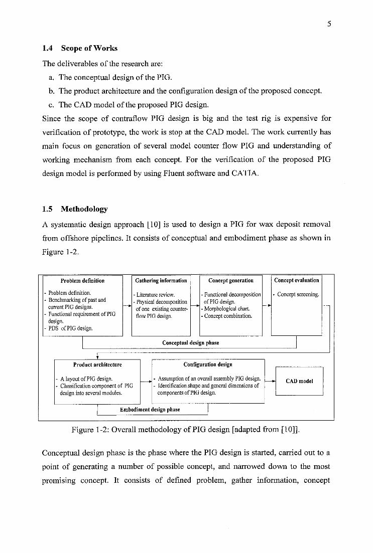
1.5 Methodology
A systematic design approach [10] is used to design a PIG for wax deposit removal
from offshore pipelines. It consists of conceptual and embodiment phase as shown in
Figure 1-2.
Problem definition
Problem definition.
Benchmarking of past andcurrent PIG designs.Functional requirement of PIGdesign.PDS of PIG design.
Gathering information
- Literature review.
- Physicaldecompositionof one existing counter-flow PIG design.
Concept generation
•Functional decompositionof PIG design.
•Morphological chart.•Conceptcombination.
Conceptual design phase
Product architecture
A layoutof PIG design.Classification component of PIGdesign intoseveralmodules.
Configuration design
- Assumption of an overall assembly PIG design.- Identification shape and general dimensions of
components of PIG design.
Embodiment design phase
Concept evaluation
- Concept screening.
*- CAD model
Figure 1-2: Overall methodology of PIG design [adapted from [10]].
Conceptual design phase is the phase where the PIG design is started, carried out to a
point of generating a number of possible concept, and narrowed down to the most
promising concept. It consists of defined problem, gather information, concept
generation and concept evaluation step. The discrete activities under conceptual
design phase are explained in the chapter five.
The most promising concept of PIG from conceptual design phase is transformed into
a physical form in the embodiment phase. It consists of product architecture and
configuration step. The detail activities in embodiment design phase are specified in
the chapter five. At the end of the design process, the proposed design of PIG is
represented in a CAD model.
1.6 Organization of Thesis
This thesis content consists of six chapters which are introduction, conventional PIG,
counterflow PIG, methodology, result and discussion and conclusion. A systematic
design approach method is adapted to meet the objective as described in the chapter
one.
Chapter one describes background of this research that covers the current
development in PIG design for offshore application. Furthermore, the objective and
scope of this research work is defined in this chapter. The methodology that is used to
design the PIG is described in this chapter.
Chapter two explains about problems in offshore pipelines and method that is used to
handle these problems. In addition, a literature review of conventional PIG and also
their limitation is discussed in this chapter.
Chapter three provides an extensive literature review of current PIG design for
unpiggable pipeline. Furthermore, a challenge in PIG development for offshore
pipeline is explained in this chapter.
Chapter four illustrates methodology that is used to design the PIG.
Chapter five describes the conceptual design and embodiment step in the PIG design.
Several new of PIG concepts that can fulfill customer needs as stated in chapter three
are generated. Furthermore, one of the PIG concepts is selected based on concept

7
selection to be further developed in the embodiment step. An abstract concept of the
proposed PIG design is then transformed into the physical form. In addition, the
layout and general dimension of each module from the proposed PIG concept is
explained. Furthermore, the final output of PIG design which is an overall assembly
of the proposed PIG design is illustrated. In additional, capabilities and limitation of
the proposed PIG design is discussed in this chapter.
Chapter six contains conclusion of this research and recommendations for further
work.
CHAPTER TWO: CONVENTIONAL PIG
2.1 Introduction
Chapter two provides some selected literature reviews that relate to the PIG. Topics
discussed in this chapter are offshore pipeline problem, method to prevent solid
deposit, PIG and utility PIG.
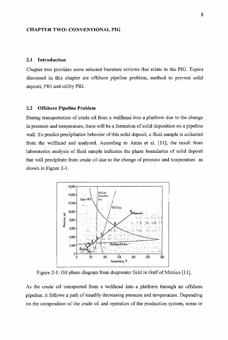
2.2 Offshore Pipeline Problem
During transportation of crude oil from a wellhead into a platform due to the change
in pressure and temperature, there will be a formation of solid deposition on a pipeline
wall. To predict precipitation behavior of this solid deposit, a fluid sample is collected
from the wellhead and analyzed. According to Amin et al. [11], the result from
laboratories analysis of fluid sample indicates the phase boundaries of solid deposit
that will precipitate from crude oil due to the change of pressure and temperature as
shown in Figure 2-1.
16,000-
ISO 200
Temperature, !F
Reservoir
Figure 2-1: Oil phase diagram from deepwater field in Gulf of Mexico [11].
As the crude oil transported from a wellhead into a platform through an offshore
pipeline, it follows a path of steadily decreasing pressure and temperature. Depending
on the composition of the crude oil and operation of the production system, some or
all the phase boundaries of solid deposit in the oil phase diagram may be passed.
Types of solid deposit that can be formed on the pipeline wall are asphaltene, wax and
hydrate. Each of them has own unique nature as explained below.
2.2.1 Wax
Paraffin is the common name for the alkane hydrocarbons with the general formula
CnH2n+2 [12]. Paraffin wax refers to the long chain paraffin with n^20-40 and has
tendency to deposit on the pipeline wall [12]. At the reservoir pressure and
temperatures condition, it remains dissolved with the produced crude oil. The
solubility of paraffin wax in the crude oil decreases drastically with the decreasing
temperature. Thus, it is easy for paraffin wax to precipitate out from the crude oil and
deposit on the pipeline wall at the low temperature. It starts to precipitate out from the
crude oil to form a solid wax phase when the crude oil temperature passes the Wax
Appearance Temperature (WAT). The deposition process of wax deposit on the
pipeline wall occurs slowly relative to the deposition process of hydrate [12, 13].
Yield strength of wax deposit can be varied in consistency from hard rock for the
highest chain length paraffin to very soft like mayonnaises oil deposit. Factors that
affect on the yield strength of wax deposit are wax contents on the deposit, cooling
rate and shear stress applied to the deposit during solidification [14]. The range of
yield strength of wax deposit is 300 to 2500 Pa [14].
2.2.2 Asphaltene
Asphaltene is a compound in the crude oil that is insoluble in n-pentane or n-hexane
but soluble in toluene or benzene [12]. It remains soluble with the crude oil under the
reservoir temperature and pressure condition. During transportation from a reservoir
to a platform, asphaltene starts to precipitate when the pressure and temperature of
crude oil across the Asphaltene Precipitation Envelope (APE). Compared to wax,
asphaltene has a characteristic of hard and brittle [12].
2.2.3 Hydrate
Natural gas hydrate is formed when methane molecules, the primary component of
natural gas, are trapped in a microscopic cage of water molecule under certain
temperature and pressure [12]. As a general rule of thumb, methane hydrate will form
10
in a natural gas system if water is available at temperature as high as 4.4°C and
pressure as low as 1.17 MPa [15]. Natural gas hydrate can be formed on the pipeline
wall as a solid or semi solid deposit. It has physical characteristics like ice and the
range of yield stress of natural gas hydrate is 4 to 12 MPa [16].
2.3 Method to Prevent Solid Deposit
An offshore pipeline that is used to transport crude oil frequently suffers from
deposition of asphaltene, wax or hydrate. As a consequence of the presence of these
depositions on the pipeline wall, the operation cost is increasing as pump capacities
need to be increased to compensate negative effects such as:
a. Reduction of the inner diameter of pipeline which leads to the flow restriction.
b. Increased of wall roughness.
c. Increased of oil viscosity.
Oil and gas industries have developed strategies to limit solid deposit formation and
clean solid deposit of the pipeline wall. Several methods that are used to handle these
deposition problems are:
a. Pipeline insulation.
The solid deposit formation occurs when the crude oil temperature and pressure
across the solid deposit boundary phase. One way to prevent the solid deposit
formation is to keep the pressure and temperature of system in the region where
the solid deposit is unstable by heating or insulation the pipelines. However,
applying insulation or heating methods to the existing subsea pipeline requires
high cost [4].
b. Chemical treatment.
A chemical inhibition can be used to slow down the formation of solid deposit on
the pipeline wall by injecting it into the pipeline. When the solid deposit already
formed on the pipeline wall, a solvent is injected continuously to the solid
deposit at a sufficient contact time. It makes the solid deposit dissolve with the
product. However, the use of chemical treatment for subsea pipeline is costly [4].
c. Pigging
Pigging is a standard operation performed by the oil companies to control a solid
deposit formation by using a scraper device. The degree of successful of pigging
11
operation depends on the hardness of the solid deposit. If the solid deposit is too
hard, usually it will be soften first by using an solvent and then a PIG will be run
to remove the solid deposit from the pipeline wall [17].
For a subsea pipeline where the hydrate is not main concern, pigging is normally the
main strategy to handle wax deposition problem on the pipeline wall [12, 18]. Since
the characteristic of hydrate is hard, conventional PIG is not recommended to remove
hydrate due to the risk of being stuck inside the pipeline [19].
Theoretically, either chemical treatment or pigging alone should be adequate to
control wax formation. In the actual pipeline operating condition neither one of these
methods can guarantee a successful wax removal. This is especially true at the
pipeline condition that carries crude oil with high cloud points, low flow velocities
and high paraffin characteristic [5]. At this pipeline condition, the wax can be rapidly
formed that make the use of chemical to disperse wax deposition is costly and the use
of PIG is not enough to control the growth of deposition.
In this research, the literature review discusses more focus on the development of PIG
that is used to remove wax on the offshore pipeline.
2.4 PIG
2.4.1 PIG Definition
The term of PIG was originally referred to a scraper driven by the fluid flow and
attached with a rake to scrape wax off the pipeline wall. One of the tales about the
origin name PIG came from the loud squealing noise that was created by the scraper
while traveling through the pipeline [20]. The others say that the name is an
abbreviation and stands for Pipeline Inspection Gauge or Pipeline Inspection Gadget
[21]. Nowadays, pipeline operators describe the PIG as a device that travels through
the pipeline for cleaning and other purposes. The process of driving the PIG through
the pipeline by the fluid is called pigging.
12
2.4.2 PIG Classification
Although the PIG was originally developed to remove solid deposit on the pipeline
wall which can restrict the flow, nowadays it is used during all phase in the life of
pipeline. The type and frequency of PIG used through the each phase in the pipeline
life is different. However, there are four main reasons for applying pigging which
affect the selection of PIG types [5]:
a. For displacement or cleaning purposes.
b. For batching or separating dissimilar products.
c. For surveying or inspection of the pipeline.
d. For maintenance of the pipeline.
The types of PIG used to accomplish these tasks can be classified into [12]:
a. Utility PIG which is used to perform function such as cleaning, separating or
dewatering.
b. Gel PIG which is used with conventional PIG to optimize pipeline dewatering,
cleaning and drying task.
c. In-line inspection tool which is used to provide information about the condition
of pipeline as well as area and location of the problem.
Since there is a wide variety of PIG available for a range of purpose, the literature
review of PIG is focused only to utility PIG which has the function of removing wax
from the pipeline.
2.5 Utility PIG
2.5.1 Utility PIG Classification
Utility PIG can be divided into two groups according to their function [12]:
a. Cleaning PIG is used to remove solid deposit from the pipeline.
b. Sealing PIG is used to provide a good seal between the PIG and pipeline either to
sweep liquid from the pipeline or to separate two dissimilar products.
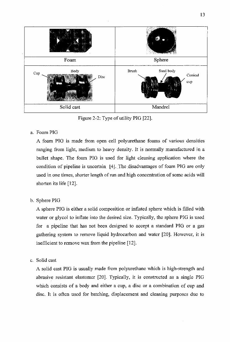
There are various types of utility PIG that can be used to remove wax. The most
common used are foam, sphere, solid cast and mandrel as shown in Figure 2-2.
13
Foam Sphere
Body Brush Steel body
Disc
Solid cast Mandrel
Figure 2-2: Type of utility PIG [22].
a. Foam PIG
A foam PIG is made from open cell polyurethane foams of various densities
ranging from light, medium to heavy density. It is normally manufactured in a
bullet shape. The foam PIG is used for light cleaning application where the
condition of pipeline is uncertain [4]. The disadvantages of foam PIG are only
used in one times, shorter length of run and high concentration of some acids will
shorten its life [12].
b. Sphere PIG
A sphere PIG is either a solid composition or inflated sphere which is filled with
water or glycol to inflate into the desired size. Typically, the sphere PIG is used
for a pipeline that has not been designed to accept a standard PIG or a gas
gathering system to remove liquid hydrocarbon and water [20]. However, it is
inefficient to remove wax from the pipeline [12].
c. Solid cast
A solid cast PIG is usually made from polyurethane which is high-strength and
abrasive resistant elastomer [20]. Typically, it is constructed as a single PIG
which consists of a body and either a cup, a disc or a combination of cup and
disc. It is often used for batching, displacement and cleaning purposes due to
14
characteristic of solid cast PIG that are economical, durable and long length of
run [12].
d. Mandrel PIG
A mandrel PIG is normally constructed with a central body tube that can be
configured with various components for specific applications. It is used for
batching, displacement and cleaning [21]. The function of cleaning is performed
by the mandrel PIG due to the positive interference between a disc or a cup of
the mandrel PIG and the pipeline wall which imparts a cleaning action on the
pipeline wall.
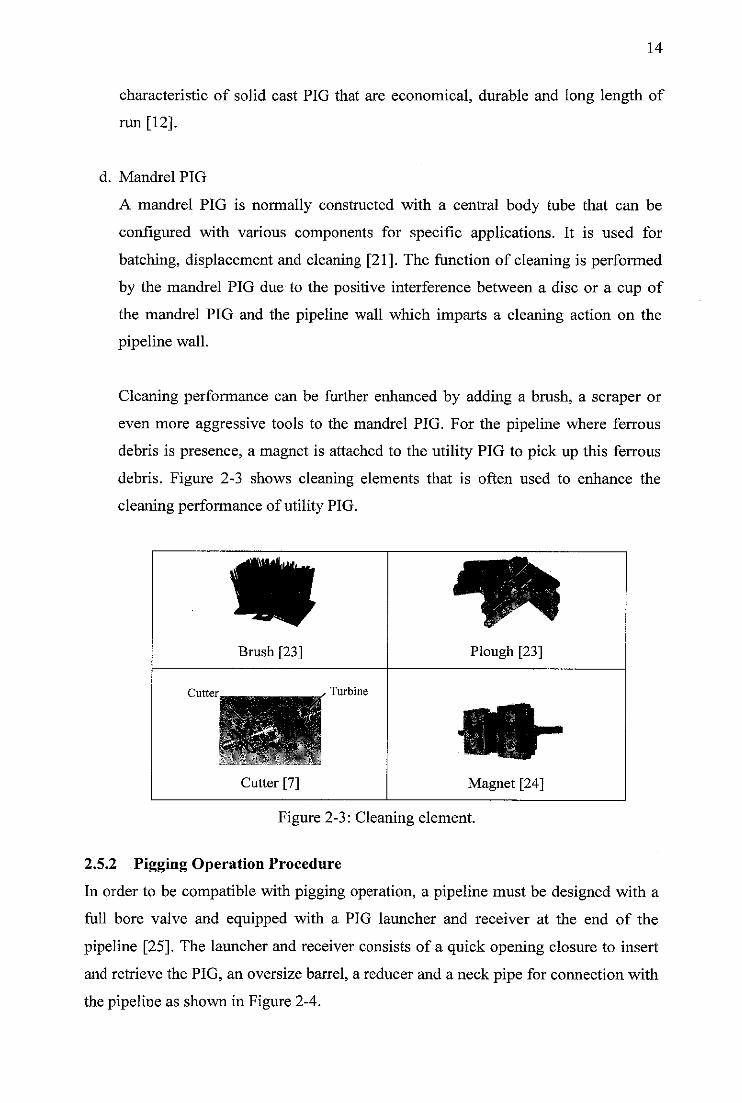
Cleaning performance can be further enhanced by adding a brush, a scraper or
even more aggressive tools to the mandrel PIG. For the pipeline where ferrous
debris is presence, a magnet is attached to the utility PIG to pick up this ferrous
debris. Figure 2-3 shows cleaning elements that is often used to enhance the
cleaning performance of utility PIG.
^M|^
Brush [23] Plough [23]
Cutter Turbine
Cutter [7] Magnet [24]
Figure 2-3: Cleaning element.
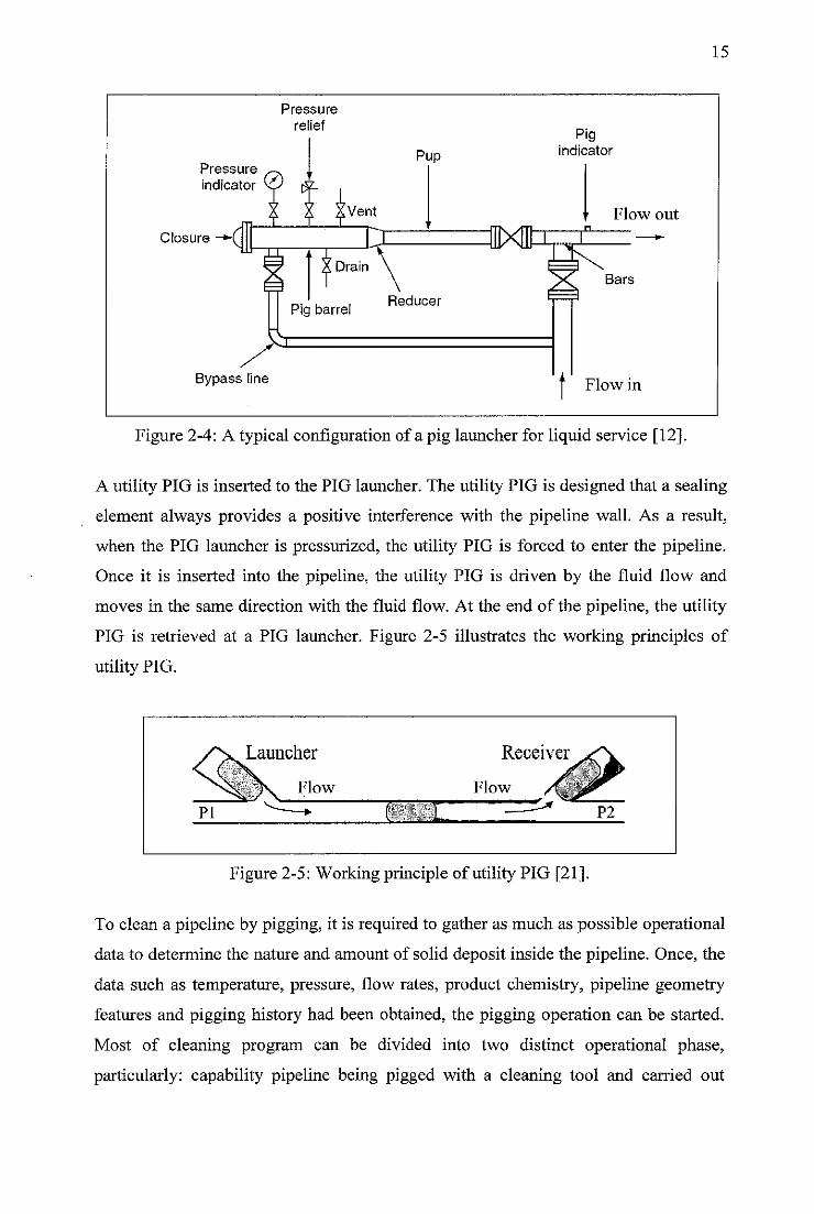
2.5.2 Pigging Operation Procedure
In order to be compatible with pigging operation, a pipeline must be designed with a
full bore valve and equipped with a PIG launcher and receiver at the end of the
pipeline [25]. The launcher and receiver consists of a quick opening closure to insert
and retrieve the PIG, an oversize barrel, a reducer and a neck pipe for connection with
the pipeline as shown in Figure 2-4.
Pressure
indicator
Closure -*-(
Bypass line
Pressure
relief
Vent
Drain
Pig barrel
Pup
DXffl
Reducer
Pigindicator
Flow out
Bars
t Flow in
15
Figure 2-4: A typical configuration of a pig launcher for liquid service [12].
A utility PIG is inserted to the PIG launcher. The utility PIG is designed that a sealing
element always provides a positive interference with the pipeline wall. As a result,
when the PIG launcher is pressurized, the utility PIG is forced to enter the pipeline.
Once it is inserted into the pipeline, the utility PIG is driven by the fluid flow and
moves in the same direction with the fluid flow. At the end of the pipeline, the utility
PIG is retrieved at a PIG launcher. Figure 2-5 illustrates the working principles of
utility PIG.
PI
Launcher
/ Flow
Receiver
Flow
Figure 2-5: Working principle of utility PIG [21].
To clean a pipeline by pigging, it is required to gather as much as possible operational
data to determine the nature and amount of solid deposit inside the pipeline. Once, the
data such as temperature, pressure, flow rates, product chemistry, pipeline geometry
features and pigging history had been obtained, the pigging operation can be started.
Most of cleaning program can be divided into two distinct operational phase,
particularly: capability pipeline being pigged with a cleaning tool and carried out
16
pipeline pigging with this cleaning tool [17]. The first phase is performed by running
a foam PIG with various foam densities. After that, the use of cleaning tool that
becomes more and more aggressive is used in the second phase. The types of cleaning
tool that is used in the second phase are a metal body attaching with either cups or
disc. If it required, such as to remove hard wax, the metal body can be attached with
scrapper blades, studs, pin or metal disc.
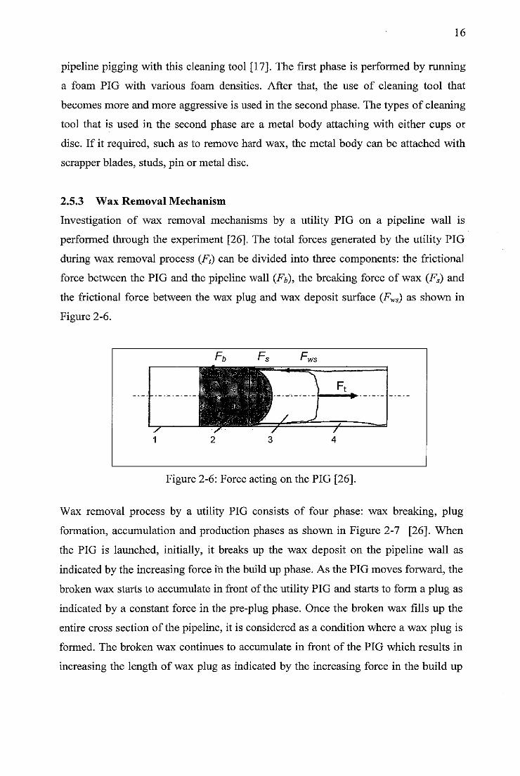
2.5.3 Wax Removal Mechanism
Investigation of wax removal mechanisms by a utility PIG on a pipeline wall is
performed through the experiment [26]. The total forces generated by the utility PIG
during wax removal process (F() can be divided into three components: the frictional
force between the PIG and the pipeline wall (Fb), the breaking force of wax (Fs) and
the frictional force between the wax plug and wax deposit surface (Fws) as shown in
Figure 2-6.
Figure 2-6: Force acting on the PIG [26].
Wax removal process by a utility PIG consists of four phase: wax breaking, plug
formation, accumulation and production phases as shown in Figure 2-7 [26]. When
the PIG is launched, initially, it breaks up the wax deposit on the pipeline wall as
indicated by the increasing force in the build up phase. As the PIG moves forward, the
broken wax starts to accumulate in front of the utility PIG and starts to form a plug as
indicated by a constant force in the pre-plug phase. Once the broken wax fills up the
entire cross section of the pipeline, it is considered as a condition where a wax plug is
formed. The broken wax continues to accumulate in front of the PIG which results in
increasing the length of wax plug as indicated by the increasing force in the build up
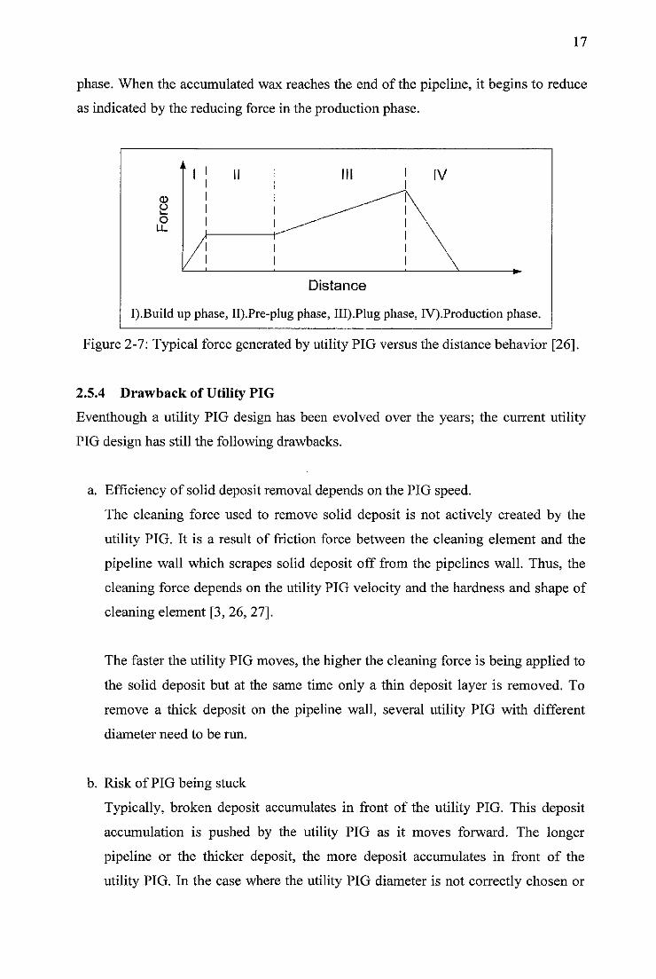
17
phase. When the accumulated wax reaches the end of the pipeline, it begins to reduce
as indicated by the reducing force in the production phase.
2o
LL
Distance
I).Build up phase, II).Pre-plug phase, III).Plug phase, IV).Production phase.
Figure 2-7: Typical force generated by utility PIG versus the distance behavior [26].
2.5.4 Drawback of Utility PIG
Eventhough a utility PIG design has been evolved over the years; the current utility
PIG design has still the following drawbacks.
a. Efficiency of solid deposit removal depends on the PIG speed.
The cleaning force used to remove solid deposit is not actively created by the
utility PIG. It is a result of friction force between the cleaning element and the
pipeline wall which scrapes solid deposit off from the pipelines wall. Thus, the
cleaning force depends on the utility PIG velocity and the hardness and shape of
cleaning element [3, 26, 27].
The faster the utility PIG moves, the higher the cleaning force is being applied to
the solid deposit but at the same time only a thin deposit layer is removed. To
remove a thick deposit on the pipeline wall, several utility PIG with different
diameter need to be run.
b. Risk of PIG being stuck
Typically, broken deposit accumulates in front of the utility PIG. This deposit
accumulation is pushed by the utility PIG as it moves forward. The longer
pipeline or the thicker deposit, the more deposit accumulates in front of the
utility PIG. In the case where the utility PIG diameter is not correctly chosen or
l:
the pipeline contains deposit thicker than predicted, the utility PIG is at risk of
being stuck due to heavy block of deposit in front of it. As a consequence,
several utility PIG with different diameter need to be run for safely deposit
removal.
c. Interrupted production during pigging process.
Various utility PIG work optimal when traveling at 1 to 5 m/sec for liquid
pipelines and 2 to 7 m/sec for gas pipelines [5]. It can not be achieved by using
normal flow production from a wellhead. As a consequence, while doing pigging
process, the production flow need to be adapted in order to conduct an
appropriate pigging procedure. In worst case, the pipeline operation needs to be
stop to rescue a stuck PIG by reversing the fluid flow. This kind of interruption
to the pipeline operation during pigging needs to be limited to a minimum level
to avoid economic losses.
Until 1994, it is estimated that there are over 300 utility PIG types available in the
market from at least 25 different manufacturer [27]. It has been developed from a
simple form of sphere into complex shape such as a metal body attaching with the
cleaning equipment. Development of this type of PIG can be considered relatively
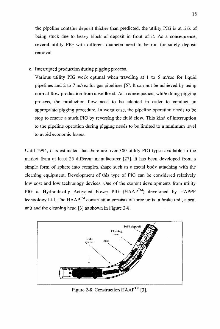
low cost and low technology devices. One of the current developments from utility
PIG is Hydraulically Activated Power PIG (HAAP™) developed by HAPPP
technology Ltd. The HAAP™ construction consists of three units: a brake unit, a seal
unit and the cleaning head [3] as shown in Figure 2-8.
^Flovf i
Brake
svslem
Cleaninihead
Solid deposit
TMFigure 2-8. Construction HAAP1M [3]
19
The HAAP™ mechanism still uses fluid flow as a drive source which makes it only
able to travel in the same direction with the fluid flow. All of the unit have opening
which make the flow able to pass through the pipeline. The pressure drop is generated
because seal and cleaning head pose a flow restriction. In a cleaning nozzle head unit,
the fluid is accelerated to create a powerful liquid jet which is used to remove solid
deposit on the pipeline wall. The advantages of this cleaning mechanism are to reduce
wax removal accumulation in front of PIG and bigger cleaning force produced. To
control the PIG speed, the HAAP™ is equipped with the brake system. It is claimed
by HAPPP technology Ltd that the HAAP™ can be traveled up 60 times slower than
the fluid velocity [3]. The capability to maintain the HAAP™ at a constant speed
ensures that the cleaning efficiency remains the same from the beginning to the end of
the pigging process.
It is suggested that the capability of PIG to travel in bidirectional can be achieved by
adding an internal power source module such as a turbine or a motor and a drive
mechanism module such a crawler and anincline wheel. Currently, the HAAP™ uses
fluid flow as a power source to drive the PIG. Therefore, it can only travel in the same
direction with the fluid flow.
As the utility PIG design becomes a matured technology, current PIG designs trend
are to develop appropriate PIG for unpiggable pipeline.
2.6 Intelligent PIG
The intelligent PIG has functions for surveying a pipeline to detect a buckle and dent
inside a pipeline and to measure pipeline thickness [5]. Since the intelligent PIG must
capture the geometry and position data from the pipeline, the pipeline condition must
be free from solid deposit on the pipeline wall before running the intelligent PIG.
Therefore, the utility PIG must be run first to clean solid deposit from the pipeline. In
order to get the accurate data, during intelligent PIG running, it needs to travel at a
constant speed [28]. Some sensor that usually uses for surveying the pipeline are
Magnetic Flux Leakage (MFL), ultrasonic, caliper survey and video camera [5].
20
CHAPTER THREE: CONTRAFLOW PIG
This chapter provides a review of current PIG development. An overview about some
PIG design development for unpiggable are discussed. In addition, an extensive
literature review of counter flow PIG development for unpiggable offshore pipeline is
also discussed in this chapter.
3.1 PIG Design Development for Unpiggable Pipeline
A piggable pipeline is a pipeline that is designed to allow a standard PIG to travel
through the entire length of the pipeline. Some of obstacles that can make the standard
PIG would not be able to negotiate it are [29] :
a. Physical obstacles
There are many of physical obstacles in the piping network that makes pigging
become impossible such as:
1. Bends/elbows (90°) with bend radius less than 1.0-D.
2. Mitered joints/elbows greater than 10°.
3. Reduced port valves.
4. Reduction/expansion in pipe diameter greater than 50-mm (2-in).
5. Unbarred branch connection.
b. Flow obstacles
The pigging process depends on the availability pressure to push the PIG through
the pipeline. The pressure level must be sufficiently great to overcome the pressure
drop across the PIG and its association pipe friction force. Typically, it needs
several hundreds PSI line pressure to drive the utility PIG. Unfortunately, not all
the operation utility works at high pressure to support the pigging process.
c. Other considerations
Some considerations that must be considered are the length of pipeline and the
availability of PIG launcher and receiver. Some of pipelines are only short pipeline
in the length of two miles which is not equipped with the PIG launcher and
receiver.
21
There are two solutions that make the pipeline becomes piggable. The first option is to
modify the pipeline so it becomes piggable in the end. However, this option in most
case is not easy to implement. It requires interrupting pipeline operation to replace the
unpiggable pipeline element which resulting in expensive cost. Another option is to
develop a PIG that is able to travel in the unpiggable pipeline. Some of developments of
the PIG design to overcome the unpiggable pipelines are discussed below.
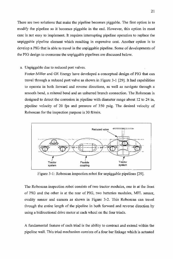
a. Unpiggable due to reduced port valves.
Foster-Miller and GE Energy have developed a conceptual design of PIG that can
travel through a reduced port valve as shown in Figure 3-1 [29]. It had capabilities
to operate in both forward and reverse directions, as well as navigate through a
smooth bend, a mitered bend and an unbarred branch connection. The Roboscan is
designed to detect the corrosion in pipeline with diameter range about 12 to 24 in,
pipeline velocity of 20 fps and pressure of 350 psig. The desired velocity of
Roboscan for the inspection purpose is 30 ft/min.
Reduced valve °=
TTractor
system
Figure 3-1: Roboscan inspection robot for unpiggable pipelines [29].
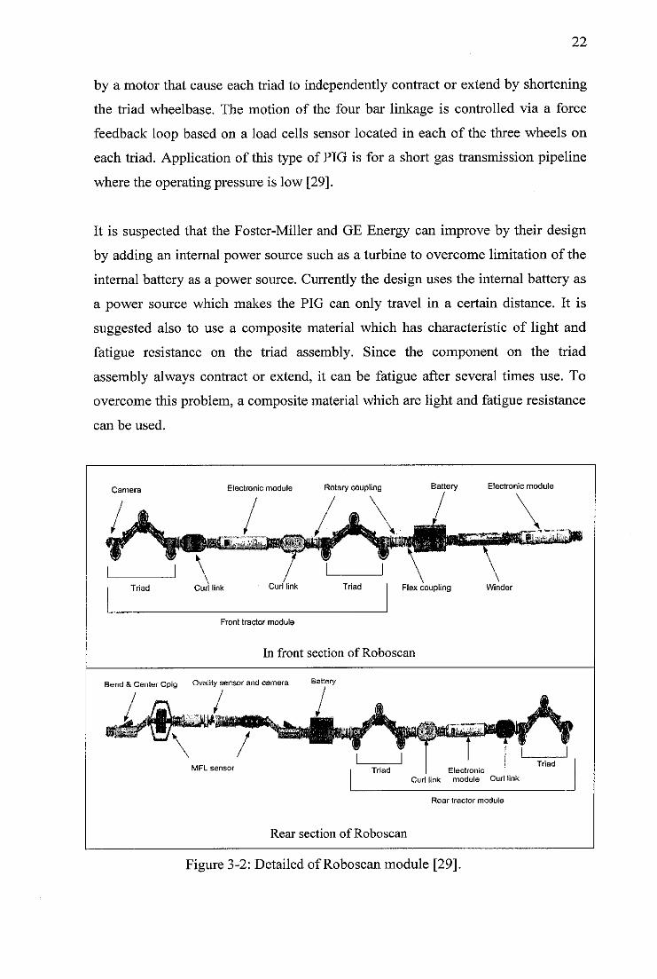
The Roboscan inspection robot consists of two tractor modules, one is at the front
of PIG and the other is at the rear of PIG, two batteries modules, MFL sensor,
ovality sensor and camera as shown in Figure 3-2. This Roboscan can travel
through the entire length of the pipeline in both forward and reverse direction by
using a bidirectional drive motor at each wheel on the four triads.
A fundamental feature of each triad is the ability to contract and extend within the
pipeline wall. This triad mechanism consists of a four bar linkage which is actuated
22
by a motor that cause each triad to independently contract or extend by shortening
the triad wheelbase. The motion of the four bar linkage is controlled via a force
feedback loop based on a load cells sensor located in each of the three wheels on
each triad. Application of this type of PIG is for a short gas transmission pipeline
where the operating pressure is low [29].
It is suspected that the Foster-Miller and GE Energy can improve by their design
by adding an internal power source such as a turbine to overcome limitation of the
internal battery as a power source. Currently the design uses the internal battery as
a power source which makes the PIG can only travel in a certain distance. It is
suggested also to use a composite material which has characteristic of light and
fatigue resistance on the triad assembly. Since the component on the triad
assembly always contract or extend, it can be fatigue after several times use. To
overcome this problem, a composite material which are light and fatigue resistance
can be used.
Camera Electronic module Rotary coupling Battery Electronic module
Triad Curl link Curl Sink Triad Flex coupling Winder
Front tractor module
In front section of Roboscan
Bend &Center Cplg Ovality sensorandcamera Battery
/
MFL sensor Triad Electronic
Curl link module Curl link
Rear section of Roboscan
Rear tractor module
Figure 3-2: Detailed of Roboscan module [29].
Triad
23
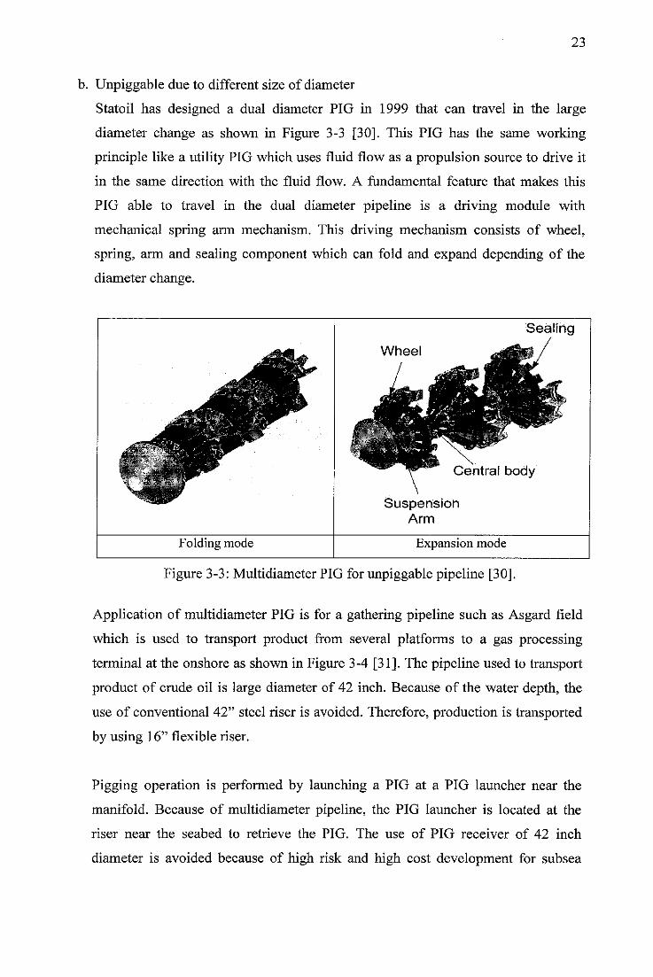
b. Unpiggable due to different size of diameter
Statoil has designed a dual diameter PIG in 1999 that can travel in the large
diameter change as shown in Figure 3-3 [30]. This PIG has the same working
principle like a utility PIG which uses fluid flow as a propulsion source to drive it
in the same direction with the fluid flow. A fundamental feature that makes this
PIG able to travel in the dual diameter pipeline is a driving module with
mechanical spring arm mechanism. This driving mechanism consists of wheel,
spring, arm and sealing component which can fold and expand depending of the
diameter change.
Folding mode
Sealing
Wheel
Central body
SuspensionArm
Expansion mode
Figure 3-3: Multidiameter PIG for unpiggable pipeline [30].
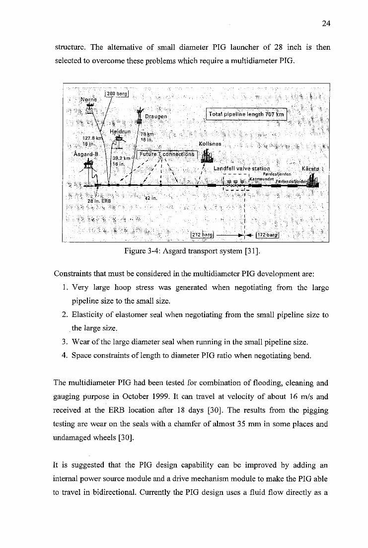
Application of multidiameter PIG is for a gathering pipeline such as Asgard field
which is used to transport product from several platforms to a gas processing
terminal at the onshore as shown in Figure 3-4 [31]. The pipeline used to transport
product of crude oil is large diameter of 42 inch. Because of the water depth, the
use of conventional 42" steel riser is avoided. Therefore, production is transported
by using 16" flexible riser.
Pigging operation is performed by launching a PIG at a PIG launcher near the
manifold. Because of multidiameter pipeline, the PIG launcher is located at the
riser near the seabed to retrieve the PIG. The use of PIG receiver of 42 inch
diameter is avoided because of high risk and high cost development for subsea
24
structure. The alternative of small diameter PIG launcher of 28 inch is then
selected to overcome these problems which require a multidiameter PIG.
Nome
Asgard-B \ | /I FutureT.connections• 39.2km /I ;:•: ;,^/16 in. . / ' / . \ "4
U •'••;.. • / , \ ', Landfall valve station Karstsf/ . —, | Ferdesfjorden
' I .„ iKarmsundet
28 in. ERB
Draugen
78.km-
16 in.
' .; \
42 in.
Total pipeline length 707 km
Kollsnes
|212barg
Figure 3-4: Asgard transport system [31].
Constraints that must be considered in the multidiameter PIG development are:
1. Very large hoop stress was generated when negotiating from the large
pipeline size to the small size.
2. Elasticity of elastomer seal when negotiating from the small pipeline size to
the large size.
3. Wear of the large diameter seal when running in the small pipeline size.
4. Space constraints of length to diameter PIG ratio when negotiating bend.
The multidiameter PIG had been tested for combination of flooding, cleaning and
gauging purpose in October 1999. It can travel at velocity of about 16 m/s and
received at the ERB location after 18 days [30]. The results from the pigging
testing are wear on the seals with a chamfer of almost 35 mm in some places and
undamaged wheels [30].
It is suggested that the PIG design capability can be improved by adding an
internal power source module and a drive mechanism module to make the PIG able
to travel in bidirectional. Currently the PIG design uses a fluid flow directly as a
25
power source to push the PIG. Therefore, it can only travel in the same direction
with the flow. To overcome this problem, an internal power source such as a
battery or a turbine can be used. Besides that, a drive mechanism such as an incline
wheel is needed for traveling in a counter flow direction. A control unit is also
needed to synchronize the umbrella mechanism with the drive mechanism. In case
where the PIG needs to travel in the same direction with the flow, the drive
mechanism needs to be switched off and the umbrella mechanism needs to be
expanding. This condition makes the fluid will push the PIG to travel in the same
direction with the flow. For traveling in a counterflow direction, the drive
mechanism will provide enough traction force while the force exerted to the
pipeline wall by the umbrella mechanism depends on the input of the sensor such
as strain gauge. Since the umbrella mechanism always expands and contracts each
time it passes the different diameter, the material use must have a resistant fatigue.
One of the alternative materials that can be used is composite because of light and
resistance fatigue characteristic.
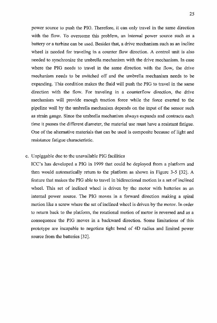
c. Unpiggable due to the unavailable PIG facilities
ICC's has developed a PIG in 1999 that could be deployed from a platform and
then would automatically return to the platform as shown in Figure 3-5 [32]. A
feature that makes the PIG able to travel in bidirectional motion is a set of inclined
wheel. This set of inclined wheel is driven by the motor with batteries as an
internal power source. The PIG moves in a forward direction making a spiral
motion like a screw where the set of inclined wheel is driven by the motor. In order
to return back to the platform, the rotational motion of motor is reversed and as a
consequence the PIG moves in a backward direction. Some limitations of this
prototype are incapable to negotiate tight bend of 4D radius and limited power
source from the batteries [32].
26
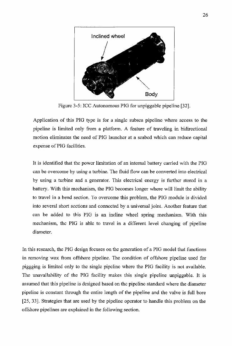
Figure 3-5: ICC Autonomous PIG for unpiggable pipeline [32].
Application of this PIG type is for a single subsea pipeline where access to the
pipeline is limited only from a platform. A feature of traveling in bidirectional
motion eliminates the need of PIG launcher at a seabed which can reduce capital
expense of PIG facilities.
It is identified that the power limitation of an internal battery carried with the PIG
can be overcome by using a turbine. The fluid flow can be converted into electrical
by using a turbine and a generator. This electrical energy is further stored in a
battery. With this mechanism, the PIG becomes longer where will limit the ability
to travel in a bend section. To overcome this problem, the PIG module is divided
into several short sections and connected by a universal joint. Another feature that
can be added to this PIG is an incline wheel spring mechanism. With this
mechanism, the PIG is able to travel in a different level changing of pipeline
diameter.
In this research, the PIG design focuses on the generation of a PIG model that functions
in removing wax from offshore pipeline. The condition of offshore pipeline used for
piggging is limited only to the single pipeline where the PIG facility is not available.
The unavailability of the PIG facility makes this single pipeline unpiggable. It is
assumed that this pipeline is designed based on the pipeline standard where the diameter
pipeline is constant through the entire length of the pipeline and the valve is full bore
[25, 33]. Strategies that are used by the pipeline operator to handle this problem on the
offshore pipelines are explained in the following section.
27
3.2 Challenges in the PIG Development for Subsea Pipeline
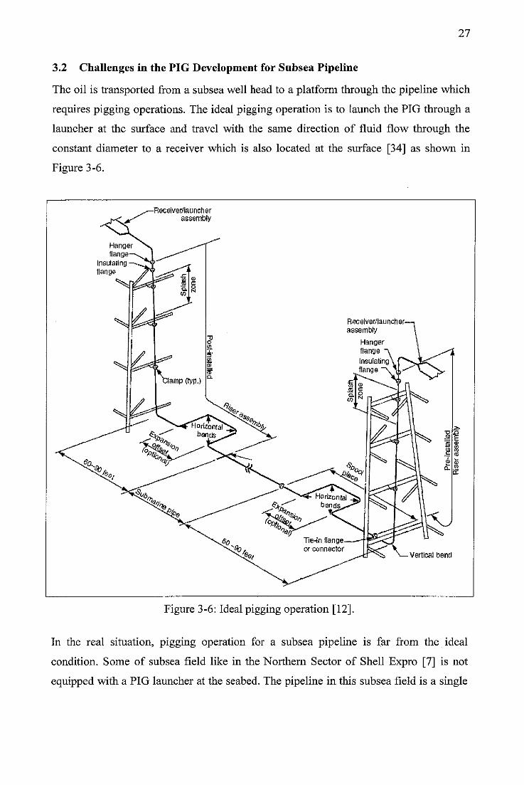
The oil is transported from a subsea well head to a platform through the pipeline which
requires pigging operations. The ideal pigging operation is to launch the PIG through a
launcher at the surface and travel with the same direction of fluid flow through the
constant diameter to a receiver which is also located at the surface [34] as shown in
Figure 3-6.
Insulatingflange
-Receiver/launcherassembly
Receiver/launcher-
assembly
Hangerflange
Insulatingflange
Figure 3-6: Ideal pigging operation [12].
Vertical bend
In the real situation, pigging operation for a subsea pipeline is far from the ideal
condition. Some of subsea field like in the Northern Sector of Shell Expro [7] is not
equipped with a PIG launcher at the seabed. The pipeline in this subsea field is a single
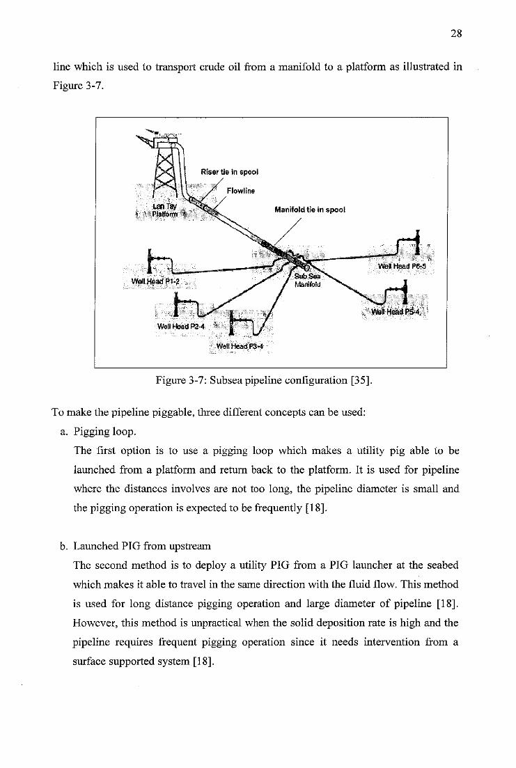
28
line which is used to transport crude oil from a manifold to a platform as illustrated in
Figure 3-7.
W6HHeadF3*4
Figure 3-7: Subsea pipeline configuration [35].
To make the pipeline piggable, three different concepts can be used:
a. Pigging loop.
The first option is to use a pigging loop which makes a utility pig able to be
launched from a platform and return back to the platform. It is used for pipeline
where the distances involves are not too long, the pipeline diameter is small and
the pigging operation is expected to be frequently [18].
b. Launched PIG from upstream
The second method is to deploy a utility PIG from a PIG launcher at the seabed
which makes it able to travel in the same direction with the fluid flow. This method
is used for long distance pigging operation and large diameter of pipeline [18].
However, this method is unpractical when the solid deposition rate is high and the
pipeline requires frequent pigging operation since it needs intervention from a
surface supported system [18].
29
c. Launched PIG from downstream.
The third method is to deploy a bidirectional PIG from a PIG launcher at the
platform. The bidirectional PIG has a module of drive mechanism which makes it
able to travel in a counter flow direction. It operates in the pipeline without tether
and generates its own power by extracting from the fluid flow. This feature makes
the bidirectional PIG able to travel through the entire length of the pipeline. If the
PIG faced an obstruction or reached at the end of the pipeline, it would
automatically return to an initial point of launching. This method eliminates the
need of PIG launcher facility at a seabed and intervention from a surface supported
system [34].
For the single offshore pipeline where it is not equipped with a PIG launcher at the
seabed, there is a definite needto develop new technologies to perform pigging process.
Since modification of an existing pipeline in a subsea is expensive, the option to build a
pigging loop and to launch a PIG from upstream is eliminated. One of the challenges in
the PIG development for subsea pipeline is to develop the PIG that can be deployed in
the limited pigging facilities without interrupted production [8], Development of
counter flow PIG with fully self-powered that may crawl in the counter flow direction
through the entire lengthof the pipeline is a solution that can solve this challenges.
3.3 State of the Art of Counter Flow PIG
Two recent developments in counter flow PIG technologies are a contraflow tetherless
pipeline crawler and a DPTcrawler [36]. The contraflow tetherless pipeline crawler had
been developed by Astec Development Ltd. for the Shell [7], The DPT crawler had
been developed by University of Durham researcher [9]. The counter flow PIG
technologies offer the great promising of solid deposit removal from the pipeline. The
solid deposit is broken down into a small chip and carried out with the fluid flow.
Therefore the chips of solid deposit will not accumulate in front the PIG or block the
PIG. At the end of the pipeline, there is a slug catcher which has a function to filter
between the gas, oil and the wax chip [12].
30
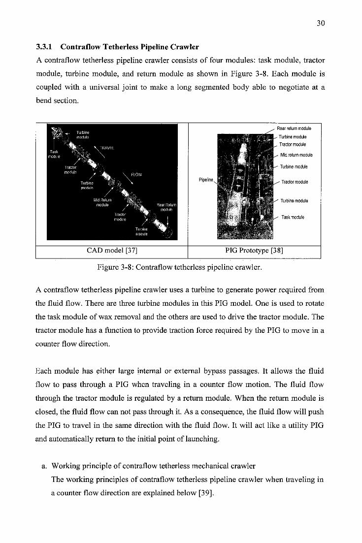
3.3.1 Contraflow Tetherless Pipeline Crawler
A contraflow tetherless pipeline crawler consists of four modules: task module, tractor
module, turbine module, and return module as shown in Figure 3-8. Each module is
coupled with a universal joint to make a long segmented body able to negotiate at a
bend section.
Pipeline
CAD model [37]
Rear return module
Turbine module
Tractor module
lid return module
- Turbine module
" Tractor module
h Jk"V Turbine module
Task module
PIG Prototype [38]
Figure 3-8: Contraflow tetherless pipeline crawler.
A contraflow tetherless pipeline crawler uses a turbine to generate power required from
the fluid flow. There are three turbine modules in this PIG model. One is used to rotate
the task module of wax removal and the others are used to drive the tractor module. The
tractor module has a function to provide traction force required by the PIG to move in a
counter flow direction.
Each module has either large internal or external bypass passages. It allows the fluid
flow to pass through a PIG when traveling in a counter flow motion. The fluid flow
through the tractor module is regulated by a return module. When the return module is
closed, the fluid flow can not pass through it. As a consequence, the fluid flow will push
the PIG to travel in the same direction with the fluid flow. It will act like a utility PIG
and automatically return to the initial point of launching.
a. Working principle of contraflow tetherless mechanical crawler
The working principles of contraflow tetherless pipeline crawler when traveling in
a counter flow direction are explained below [39].
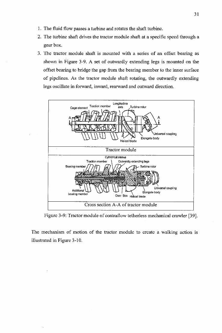
31
1. The fluid flow passes a turbine and rotates the shaft turbine.
2. The turbine shaft drives the tractor module shaft at a specific speed through a
gear box.
3. The tractor module shaft is mounted with a series of an offset bearing as
shown in Figure 3-9. A set of outwardly extending legs is mounted on the
offset bearing to bridge the gap from the bearing member to the inner surface
of pipelines. As the tractor module shaft rotating, the outwardly extending
legs oscillate in forward, inward, rearward and outward direction.
LongitudinalCage element Traclicn ™mber axis yTurbine rotor
\t
1W1Helical blade
Tractor module
\ Universal couplingElongate body
Cylindrical sleeve
Traction member \ Outwardly extending legsBearing member // //TP) IA)\ fs^f Ls^Th^- Turbine rotor
Additional
bearing memberGear Box
Universal coupling
Elongate body
(Ileal blade
Cross section A-A of tractor module
Figure 3-9: Tractor module of contraflow tetherless mechanical crawler [39].
The mechanism of motion of the tractor module to create a walking action is
illustrated in Figure 3-10.
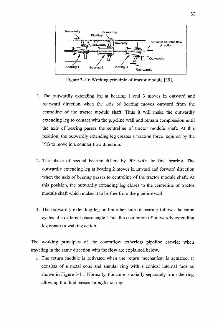
Rearward ly ForwardfyPipeline V
Inwardly
Bearing 2 Bearing 3
Travel in counter-flow
s- direction
Outwardly
Rearward ly
32
Figure 3-10: Working principle of tractor module [39].
1. The outwardly extending leg at bearing 1 and 3 moves in outward and
rearward direction when the axis of bearing moves outward from the
centreline of the tractor module shaft. Thus it will make the outwardly
extending leg to contact with the pipeline wall and remain compression until
the axis of bearing passes the centreline of tractor module shaft. At this
position, the outwardly extending leg creates a traction force required by the
PIG to move in a counter flow direction.
2. The phase of second bearing differs by 90° with the first bearing. The
outwardly extending leg at bearing 2 moves in inward and forward direction
when the axis of bearing passes to centreline of the tractor module shaft. At
this position, the outwardly extending leg closes to the centreline of tractor
module shaft which makes it to be free from the pipeline wall.
3. The outwardly extending leg on the other side of bearing follows the same
cycles at a different phase angle. Thus the oscillation of outwardly extending
leg creates a walking action.
The working principles of the contraflow tetherless pipeline crawler when
traveling in the same direction with the flow are explained below.
1. The return module is activated when the return mechanism is actuated. It
consists of a metal cone and annular ring with a conical internal face as
shown in Figure 3-11. Normally, the cone is axially separately from the ring
allowing the fluid passes through the ring.
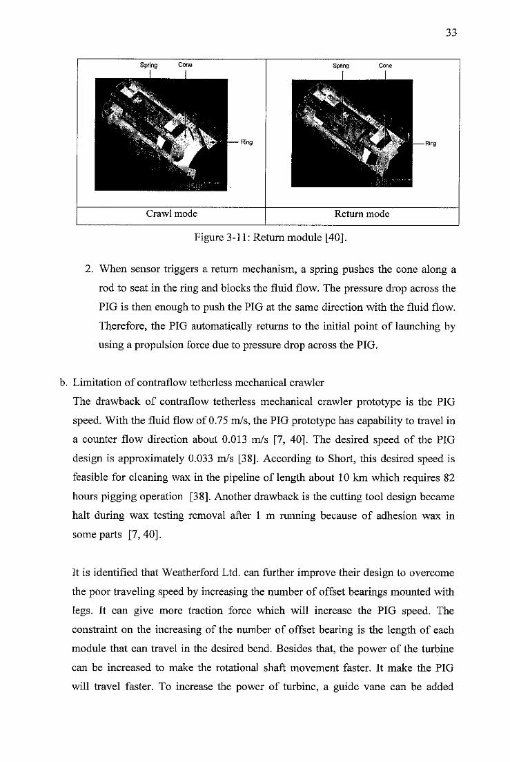
33
Spring Cone Spring Cone
Crawl mode Return mode
Figure 3-11: Return module [40].
2. When sensor triggers a return mechanism, a spring pushes the cone along a
rod to seat in the ring and blocks the fluid flow. The pressure drop across the
PIG is then enough to push the PIG at the same direction with the fluid flow.
Therefore, the PIG automatically returns to the initial point of launching by
using a propulsion force due to pressure drop across the PIG.
b. Limitation of contraflow tetherless mechanical crawler
The drawback of contraflow tetherless mechanical crawler prototype is the PIG
speed. With the fluid flow of 0.75 m/s, the PIG prototype has capability to travel in
a counter flow direction about 0.013 m/s [7, 40]. The desired speed of the PIG
design is approximately 0.033 m/s [38]. According to Short, this desired speed is
feasible for cleaning wax in the pipeline of length about 10 km which requires 82
hours pigging operation [38]. Another drawback is the cutting tool design became
halt during wax testing removal after 1 m running because of adhesion wax in
some parts [7, 40].
It is identified that Weatherford Ltd. can further improve their design to overcome
the poor traveling speed by increasing the number of offset bearings mounted with
legs. It can give more traction force which will increase the PIG speed. The
constraint on the increasing of the number of offset bearing is the length of each
module that can travel in the desired bend. Besides that, the power of the turbine
can be increased to make the rotational shaft movement faster. It make the PIG
will travel faster. To increase the power of turbine, a guide vane can be added
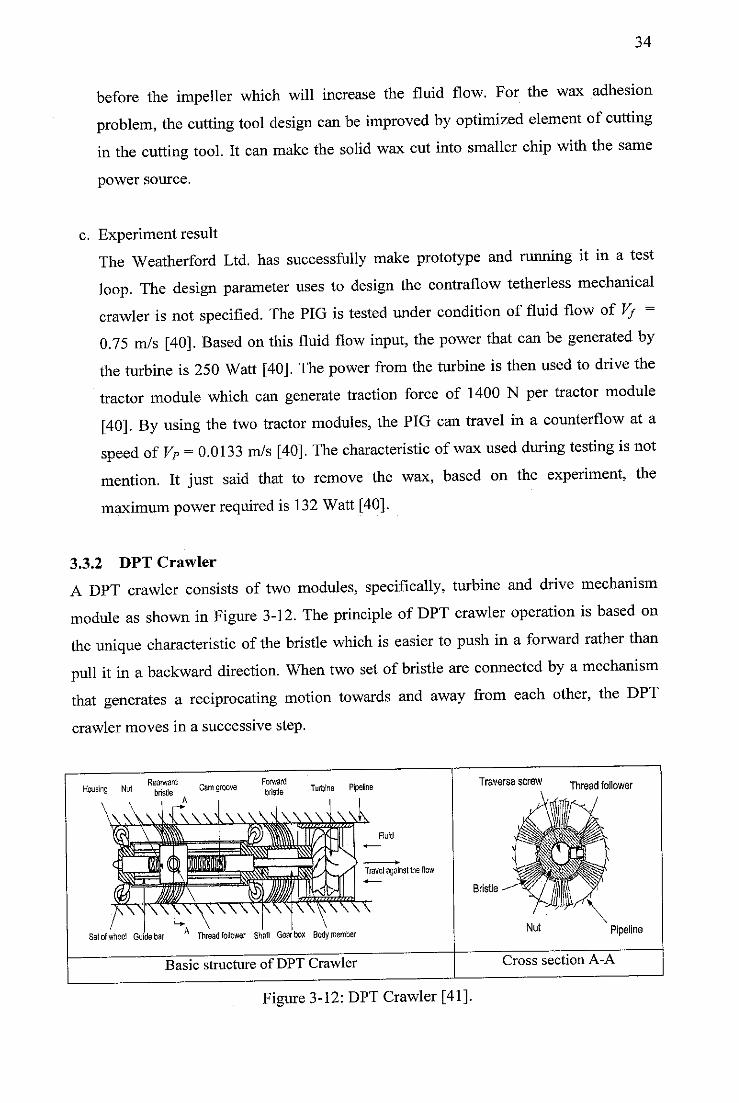
34
before the impeller which will increase the fluid flow. For the wax adhesionproblem, the cutting tool design can be improved by optimized element ofcuttingin the cutting tool. It can make the solid wax cut into smaller chip with the same
power source.
c. Experiment result
The Weatherford Ltd. has successfully make prototype and running it in a test
loop. The design parameter uses to design the contraflow tetherless mechanicalcrawler is not specified. The PIG is tested under condition of fluid flow of Vf =0.75 m/s [40]. Based on this fluid flow input, the power that can be generated bythe turbine is 250 Watt [40]. The power from the turbine is then used to drive thetractor module which can generate traction force of 1400 N per tractor module[40]. By using the two tractor modules, the PIG can travel in a counterflow at aspeed of VP =0.0133 m/s [40]. The characteristic of wax used during testing is notmention. It just said that to remove the wax, based on the experiment, themaximum power required is 132 Watt [40].
3.3.2 DPT Crawler
A DPT crawler consists of two modules, specifically, turbine and drive mechanism
module as shown in Figure 3-12. The principle ofDPT crawler operation is based onthe unique characteristic of the bristle which is easier to push in a forward rather thanpull it in abackward direction. When two set of bristle are connected by a mechanismthat generates a reciprocating motion towards and away from each other, the DPTcrawler moves in a successive step.
Rearward „ Forward „. ,.Housing Ngl b|We Camgroove bfist|e Turbine PipelineA
Fluid
Travel againsllhe flow
WCV^TO<WxSelofwheel Gudebar A Thread follower Shaft Gearbox Bodymember
Basic structure of DPT Crawler
Traverse screw Thread foiiower
Bristle
Pipeline
Cross section A-A
Figure 3-12: DPT Crawler [41].
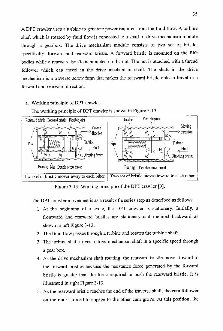
35
A DPT crawler uses a turbine to generate power required from the fluid flow. A turbine
shaft which is rotated by fluid flow is connected to a shaft of drive mechanism module
through a gearbox. The drive mechanism module consists of two set of bristle,
specifically: forward and rearward bristle. A forward bristle is mounted on the PIG
bodies while a rearward bristle is mounted on the nut. The nut is attached with a thread
follower which can travel in the drive mechanism shaft. The shaft in the drive
mechanism is a traverse screw form that makes the rearward bristle able to travel in a
forward and rearward direction.
a. Working principle of DPT crawler
The working principle of DPT crawler is shown in Figure 3-13.
Rearward bristle Forward bristle Flexiblejoint
mw///w///////})jv//////j/s//w////\ Movingdirection
, ^Directing device
Bearing Nut Double screw thread
Two set of bristle moves away to each other
Brushes Flexiblejoint
J^C. Directing device
Bearing Double screw thread
Two set of bristle moves toward to each other
Figure 3-13: Working principle of the DPT crawler [9].
The DPT crawler movement is as a result of a series step as described as follows.
1. At the beginning of a cycle, the DPT crawler is stationary. Initially, a
frontward and rearward bristles are stationary and inclined backward as
shown in left Figure 3-13.
2. The fluid flow passes through a turbine and rotates the turbine shaft.
3. The turbine shaft drives a drive mechanism shaft in a specific speed through
a gear box.
4. As the drive mechanism shaft rotating, the rearward bristle moves toward to
the forward bristles because the resistance force generated by the forward
bristle is greater than the force required to push the rearward bristle. It is
illustrated in right Figure 3-13.
5. As the rearward bristle reaches the end of the traverse shaft, the cam follower
on the nut is forced to engage to the other cam grove. At this position, the
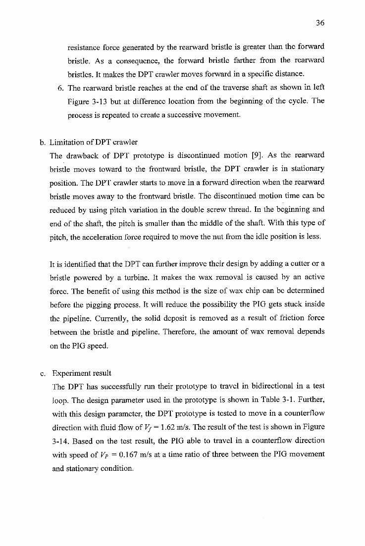
36
resistance force generated by the rearward bristle is greater than the forward
bristle. As a consequence, the forward bristle farther from the rearward
bristles. It makes the DPT crawler moves forward in a specific distance.
6. The rearward bristle reaches at the end of the traverse shaft as shown in left
Figure 3-13 but at difference location from the beginning of the cycle. The
process is repeated to create a successive movement.
b. Limitation of DPT crawler
The drawback of DPT prototype is discontinued motion [9]. As the rearward
bristle moves toward to the frontward bristle, the DPT crawler is in stationary
position. The DPT crawler starts to move in a forward directionwhen the rearward
bristle moves away to the frontward bristle. The discontinued motion time can be
reduced by using pitch variation in the double screw thread. In the beginning and
end of the shaft, the pitch is smaller than the middle of the shaft. With this type of
pitch, the accelerationforce required to move the nut from the idle position is less.
It is identified that the DPT can further improve their design by adding a cutter or a
bristle powered by a turbine. It makes the wax removal is caused by an active
force. The benefit of using this method is the size of wax chip can be determined
before the pigging process. It will reduce the possibility the PIG gets stuck inside
the pipeline. Currently, the solid deposit is removed as a result of friction force
between the bristle and pipeline. Therefore, the amount of wax removal depends
on the PIG speed.
c. Experiment result
The DPT has successfully run their prototype to travel in bidirectional in a test
loop. The design parameter used in the prototype is shown in Table 3-1. Further,
with this design parameter, the DPT prototype is tested to move in a counterflow
directionwith fluid flow of Vf = 1.62m/s. The result of the test is shown in Figure
3-14. Based on the test result, the PIG able to travel in a counterflow direction
with speed of Vp =0.167 m/s at a time ratio of three between the PIG movement
and stationary condition.
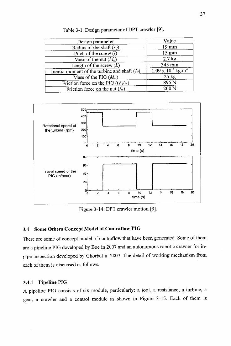
Table 3-1. Design parameter of DPT crawler [9].
Design parameter Value
Radius of the shaft (rd) 19mm
Pitch of the screw (I) 15 mm
Mass of the nut (Mn) 2.7 kg
Length of the screw (L) 345 mm
Inertia moment of the turbine and shaft (Q 1.09xlO"Jkg.m^Mass of the PIG (Mm) 25 kg
Friction force on the PIG ((FP)P) 895 N
Friction force on the nut (fm) 200 N
Rotational speed ofthe turbine (rpm) aoofr
100
0
Travel speed of thePIG (m/hour)
40-
20
4 6*„*.«—J-.—^—,i-
10 12
time (s)
10 12
time (s)
*16 13™
14 18 20
37
Figure 3-14: DPT crawler motion [9].
3.4 Some Others Concept Model of Contraflow PIG
There are some of concept model of contraflow thathave beengenerated. Some of them
are a pipeline PIG developed by Boe in2007 and an autonomous robotic crawler for in-pipe inspection developed by Ghorbel in 2007. The detail of working mechanism from
each of them is discussed as follows.
3.4.1 Pipeline PIG
A pipeline PIG consists of six module, particularly: a tool, a resistance, a turbine, a
gear, a crawler and a control module as shown in Figure 3-15. Each of them is
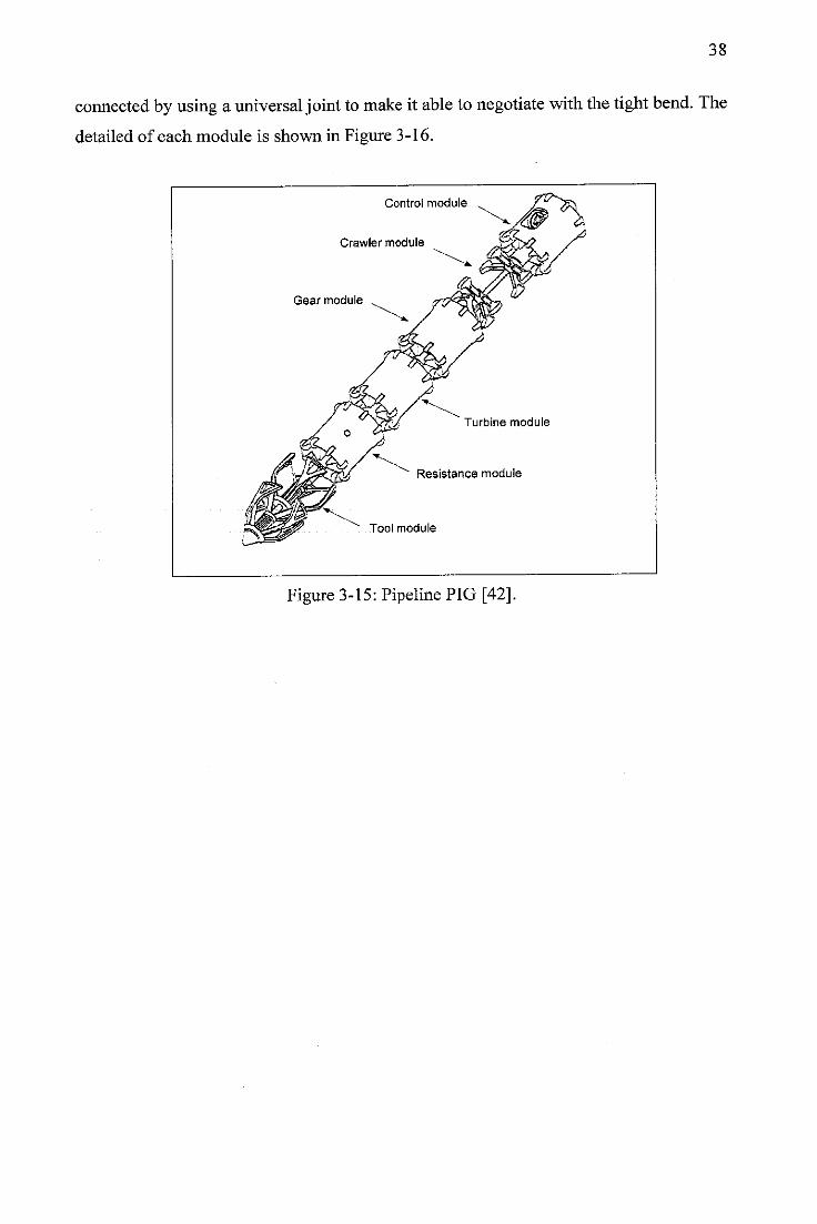
38
connected by using a universal jointto make it able to negotiate withthe tightbend. The
detailed of each module is shown in Figure 3-16.
Control module
Crawler module
Gear module
Turbine module
Resistance module
Tool module
Figure 3-15: Pipeline PIG [42].
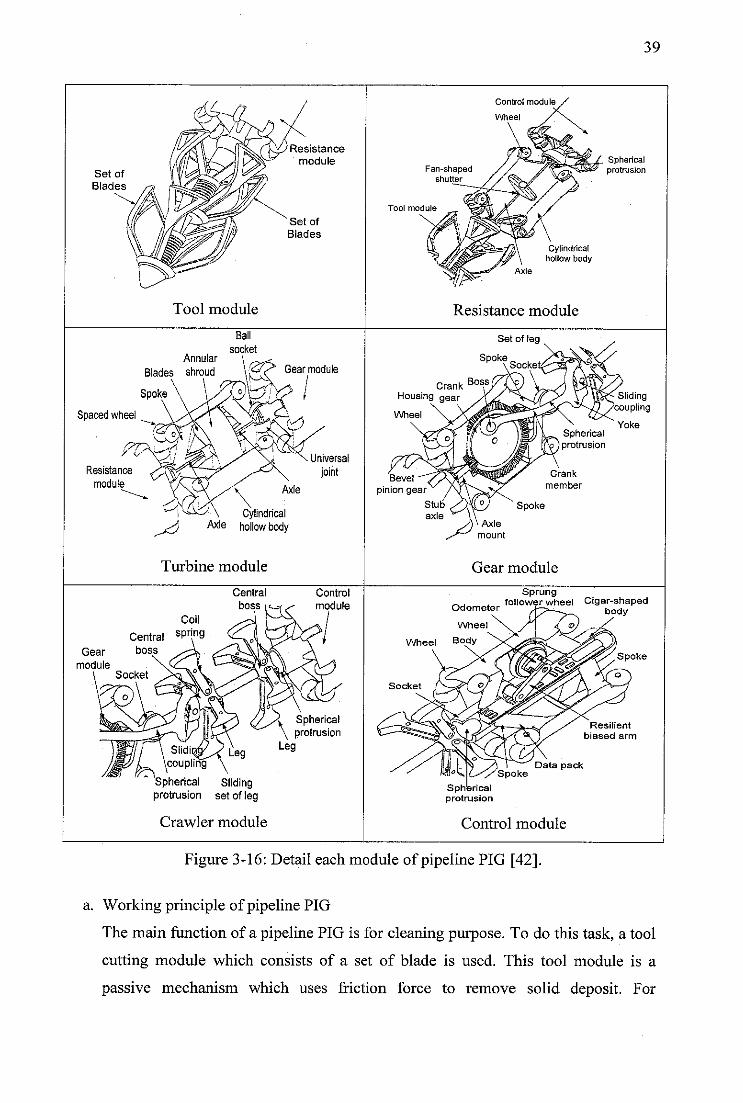
Set of
Blades
Spaced wheel
Resistance
module
Resistance
module
Set of
Blades
Tool module
Annular
Blades shroud
Ball
socket
Gear module
Cylindrical^} Axle hollow body
Turbine module
Central
boss
Universal
joint
Control
module
Coil
Central sPr[n9bossGear
moduleSocket
\ Sli\cou
li'lZ^y (/^/\ Spherical/ ll^\ \ Protrusi°n
pling \
Spherical Slidingprotrusion set of leg
Crawler module
Fan-shapedshutter
Tool module
Control module
Wheel
Cylindricalhollow body
Resistance module
Crank
Housing gear
Wheel
Axle
mount
Crank
member
Spoke
Gear module
39
Sphericalprotrusion
Sliding'coupling
Yoke
Sprungfollower wheel Cigar-shaped
body
Wheel
Odometer
Wheel
Body
Spherical
Data pack
protrusion
Control module
Spoke
Figure 3-16: Detail each module of pipeline PIG [42].
a. Working principle of pipeline PIG
The main function of a pipeline PIG is for cleaning purpose. To do this task, a tool
cutting module which consists of a set of blade is used. This tool module is a
passive mechanism which uses friction force to remove solid deposit. For
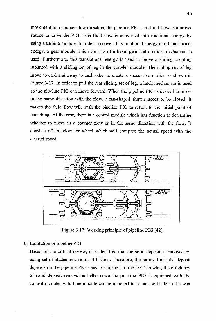
40
movement in a counter flow direction, the pipeline PIG uses fluid flow as a power
source to drive the PIG. This fluid flow is converted into rotational energy by
using a turbine module. In order to convert this rotational energy into translational
energy, a gear module which consists of a bevel gear and a crank mechanism is
used. Furthermore, this translational energy is used to move a sliding coupling
mounted with a sliding set of leg in the crawler module. The sliding set of leg
move toward and away to each other to create a successive motion as shown in
Figure 3-17. In order to pull the rear sliding set of leg, a latch mechanism is used
so the pipeline PIG can move forward. When the pipeline PIG is desired to move
in the same direction with the flow, a fan-shaped shutter needs to be closed. It
makes the fluid flow will push the pipeline PIG to return to the initial point of
launching. At the rear, there is a control module which has function to determine
whether to move in a counter flow or in the same direction with the flow. It
consists of an odometer wheel which will compare the actual speed with the
desired speed.
Figure 3-17: Working principle ofpipeline PIG [42].
b. Limitation of pipeline PIG
Based on the critical review, it is identified that the solid deposit is removed by
using set of blades as a result of friction. Therefore, the removal of solid deposit
depends on the pipeline PIG speed. Compared to the DPT crawler, the efficiency
of solid deposit removal is better since the pipeline PIG is equipped with the
control module. A turbine module can be attached to rotate the blade so the wax
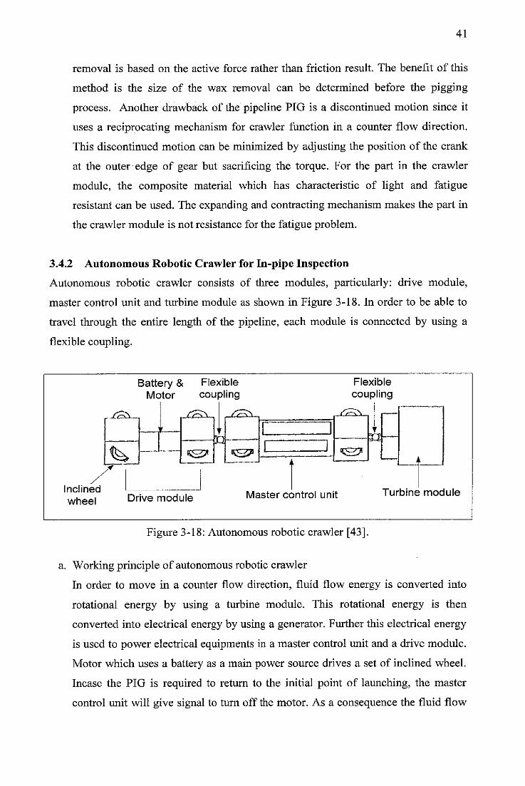
41
removal is based on the active force rather than friction result. The benefit of this
method is the size of the wax removal can be determined before the pigging
process. Another drawback of the pipeline PIG is a discontinued motion since it
uses a reciprocating mechanism for crawler function in a counter flow direction.
This discontinued motion can be minimized by adjusting the position of the crank
at the outer edge of gear but sacrificing the torque. For the part in the crawler
module, the composite material which has characteristic of light and fatigue
resistant can be used. The expanding and contracting mechanism makes the part in
the crawler module is not resistance for the fatigue problem.
3.4.2 Autonomous Robotic Crawler for In-pipe Inspection
Autonomous robotic crawler consists of three modules, particularly: drive module,
master control unit and turbine module as shown in Figure 3-18. In order to be able to
travel through the entire length of the pipeline, each module is connected by using a
flexible coupling.
Inclined
wheel
Battery & FlexibleMotor coupling
.JxS^-, /TRY
'
% •sjS^*
£3
Drive module
Flexible
coupling
~£2[rS?
Master control unit Turbine module
Figure 3-18: Autonomous robotic crawler [43].
a. Working principle of autonomous robotic crawler
In order to move in a counter flow direction, fluid flow energy is converted into
rotational energy by using a turbine module. This rotational energy is then
converted into electrical energy by using a generator. Further this electrical energy
is used to power electrical equipments in a master control unit and a drive module.
Motor which uses a battery as a main power source drives a set of inclined wheel.
Incase the PIG is required to return to the initial point of launching, the master
control unit will give signal to turn off the motor. As a consequence the fluid flow
42
still flowing, the PIG will be pushed by the fluid flow to travel in the same
direction with the flow.
b. Limitation of autonomous robotic crawler
Based on the critical review, it is suspected the movement of autonomous robotic
crawler is continues since using a wheel mechanism. Compared to the other
concept such as a contraflow tetherless mechanical crawler, a DPT crawler and a
pipeline PIG, the traction force generated by a drive module is smaller. To
overcome this drawback, a pitch of inclined wheel needs to be reduced. As a
consequence, the pipeline PIG travels slower but more traction forces generated.
The PIG can be added another feature for specific function such as cleaning by
adding a set of blade or a bristle or inspection by adding an ultrasonic or a MFL
sensor. A spring mechanism can be attached to the inclined wheel feature to
overcome problem when passing the dent.
3.5 Customer Need of PIG Design
Oil companies have identified that pigging operation in single offshore pipelines would
be advantageous by using bidirectional PIG types. From literature review, the customer
needs of PIG design for wax removal from pipelines are:
a. It is desired that the PIG is able to be launched from a platform and travel against
the flow through the entire length of the pipeline [7-9, 32].
b. It is desired that the PIG extracts the power from the fluid flow and use it to drive
the PIG to travel in a bidirectional motion [7-9, 32].
c. While doing cleaning, it is desired that the cleaning force is actively generated by
the PIG [3].
d. It is desired that during the wax removal process, the PIG travels a constant speed
to control amount the wax removal and to avoid wax accumulation in front of the
PIG [3,7,8,28].
e. When the PIG reached the end of the pipeline, it is desired that the PIG would
automatically return to the initial point of launching [7-9, 32].
43
This research focuses on the producing a proposed CAD model of bidirectional PIG that
can fulfill customer needs as described before. The benefits of development this PIG
type is:
a. Reduce capital expense
Since the PIG can be deployed from a surface at a platform, the need of PIG
launcher at a seabed is eliminated. It can save a cost on the capital expense of PIG
facilities.
b. No disruption to production
PIG uses normal fluid flow as a power source. Fluid flow is converted into
rotational energy which is used to drive the PIG in a counter flow direction and to
rotate a cutter tool. Since the PIG uses normal fluid flow operation while doing
pigging, production process is undisrupted. The amount of wax removal is also in
controllable because it is removed by an active force. The risk of PIG being stuck
due to wax accumulation in front of the PIG is reduced with this feature.
Therefore, the possibility of production to be stop in order to retrieve the stuck PIG
inside a pipeline is small.
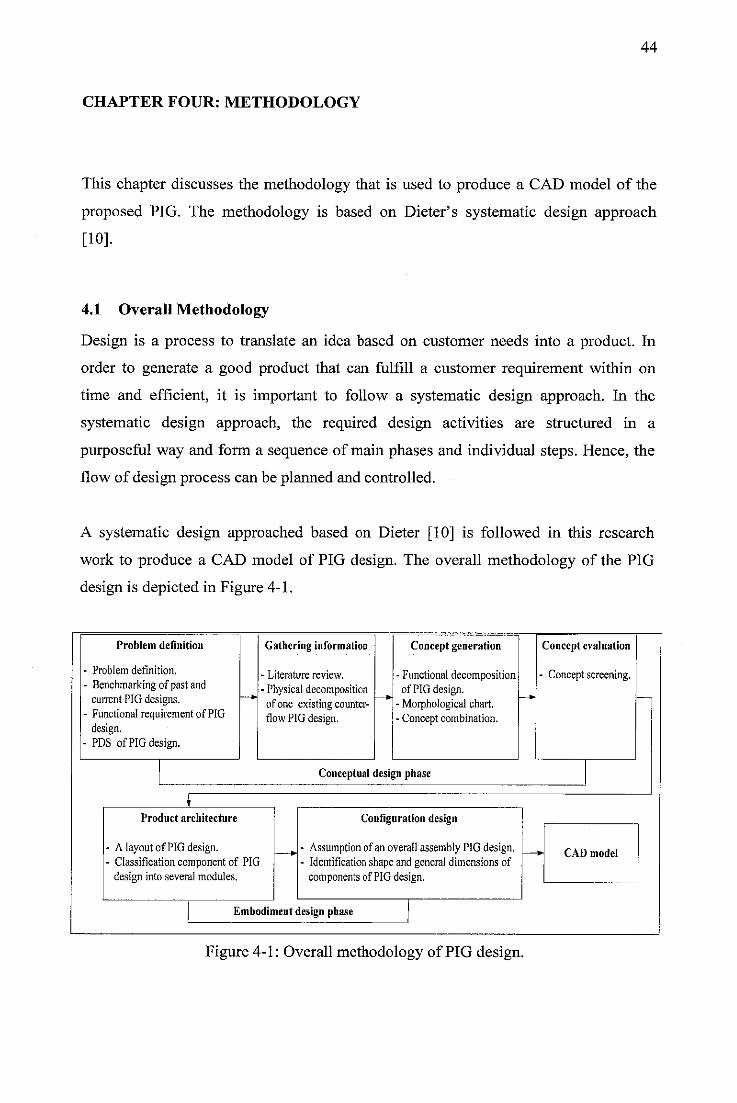
44
CHAPTER FOUR: METHODOLOGY
This chapter discusses the methodology that is used to produce a CAD model of the
proposed PIG. The methodology is based on Dieter's systematic design approach
[10].
4.1 Overall Methodology
Design is a process to translate an idea based on customer needs into a product. In
order to generate a good product that can fulfill a customer requirement within on
time and efficient, it is important to follow a systematic design approach. In the
systematic design approach, the required design activities are structured in a
purposeful way and form a sequence of main phases and individual steps. Hence, the
flow of design process can be planned and controlled.
A systematic design approached based on Dieter [10] is followed in this research
work to produce a CAD model of PIG design. The overall methodology of the PIG
design is depicted in Figure 4-1.
Problem definition
Problem definition.
Benchmarking of past andcurrentPIG designs.Functional requirement of PIGdesign.PDS of PIG design.
Gathering information
- Literature review.
• Physicaldecompositionof one existingcounter-flowPIGdesign.
Concept generation
•Functional decompositionof PIG design.
•Morphological chart.•Concept combination.
Conceptualdesign phase
Product architecture
A layoutof PIG design.Classification component of PIGdesign into several modules.
Configuration design
- Assumption ofan overallassembly PIG design.- Identification shapeand general dimensions of
components of PIGdesign.
Embodiment design phase
Figure 4-1: Overall methodology of PIG design.
Concept evaluation
- Concept screening.
* CAD model
45
The steps in conceptual and embodiment design phase and also activities in each steps
is explained in detailed below.
4.1.1 Conceptual Design Phase
Conceptual design phase is a phase where the PIG design problem is defined,
generating several potential concepts of PIG design and selecting one of the
promising concept. The steps under conceptual design phase are problem definition,
gathering information, concept generation and concept evaluation.
4.1.1.1 Problem Definition Step
The problem definition step consists of problem definition, benchmarking, functional
requirement and Product Design Specification (PDS) of the PIG design activities.
Initially a statement about the purpose of the PIG design is created. Furthermore,
benchmarking of past and current PIG design is performed to find strong points and
drawbacks from the previous PIG design. A set of function requirements of PIG
design are created based on benchmarking to improve the drawbacks from the
previous design. Constraints that can quantify performance of PIG design for each
requirement are defined in PDS.
4.1.1.2 Gathering Information Step
The gathering information step consists of literature review and physical
decomposition of one existing current PIG design activities.
Study literature of the related PIG designs are explored in the gathering information
step to gain understanding about working principle from previous designs. Further,
one of the current PIG design is chosen as a datum for the PIG design development.
Functions required to carry out the overall function from the datum design is studied
through a physical decomposition. These functions will be used to assist in
determining the detail function of PIG design,
4.1.1.3 Concept Generation Step
The concept generation step consists of functional decomposition, morphological
chart and concept combination activities.
46
A working principle of PIG design is established in the concept generation step by
using a functional decomposition approach. It is started by defining the overall
function of PIG design. Further, the overall function of PIG design is decomposed
into sub-functions. These sub-functions are then arranged in a logical order which will
transform initial input into desired output in terms of energy, material and information
flow.
Sub-functions that are required to accomplish the overall function of PIG design is
then mapped into a morphological chart. Furthermore, solutions that can fulfill the
sub-functions are explored through a literature review and brainstorming. Several
alternative concepts of PIG design are generated by combining solution from each
sub-function.
4.1.1.4 Concept Evaluation Step
Several alternative concepts of PIG design that are produced in the concept generation
step are narrowed down into a single best concept. A method used to select the most
promising concept is a concept screening. In the concept screening, relative
performance from each concept is compared to a datum of one existing PIG design for
particular criteria which is created based on the functional requirement of PIG design.
The outcome of conceptual design phase is one of the most promising concepts of
PIG design.
4.1.2 Embodiment Design Phase
In the embodiment design phase, the abstract concept of the most promising PIG
design from conceptual design phase is transformed into a physical component. The
steps under the embodiment design phase are product architecture and configuration
design.
4.1.2.1 Product Architecture
A layout of the most promising PIG design is drawn roughly to show the arrangement
of the selected component and illustrate their shape and sizes. Furthermore, a physical
component that contributes to the same function is clustered into the same module.
47
4.1.2.2 Configuration Design
The proposed design of PIG consists of several modules where each module consists
of several components. Initially, the number and dimension of some component in the
overall assembly of PIG design is assumed based on the rule of thumb from previous
design. Furthermore, the feature and dimension of critical components is determined
through a preliminary analysis. For other standard components that are insignificant to
the overall performance of PIG design and can be obtained from the manufacturer, an
analysis is performed only to determine the type, size and specification of its
component.
4.1.3 CAD Model
A CAD model of PIG design is produced at the end of design process. It illustrates the
overall assembly of the PIG design and component required to accomplish the overall
function of PIG design.
4.2 Tools
The tools used in this research work are:
1. CATIA[44]
CATIA software is used to draw the component of PIG design. An overall
assembly of the PIG design is illustrated by using assembly design module in
CATIA software.
2. Fluent [45]
The performance of a device that is used to convert hydraulic energy into
rotational energy is simulated in Fluent software.
48
CHAPTER FIVE: RESULT AND DISCUSSION
5.1 Introduction
Conceptual and embodiment design phase of PIG design is discussed in chapter five.
In the beginning, conceptual design phase is discussed first and then followed by the
embodiment design phase. The final output of the design process which is a CAD
model of PIG design is illustrated at the end of this chapter.
5.2 Conceptual Design
The first step in the conceptual design phase is problem definition where the PIG
design problems are generated based on the customer requirements. Furthermore, the
relevant information about the PIG design is performed in the gathering information
step. In addition, several new concept of PIG design are generated in the concept
generation. At the end, the most promising concept is selected in the concept
evaluation step.
5.2.1 Problem Definition
Initially, the design process is started by defining the problem of current PIG design.
Activities in a defined problem step consist of identifying customer requirement,
benchmarking of past and current PIG design, functional requirement of the PIG
design and PDS of the PIG design activities.
a. Identifying customer requirements
A product is designed and developed because there is an opportunity to sell the
product in a market. In order to success in the market, the product design must be
developed based on the customer requirements. It can be obtained through [10,
46]:
1. A document of customer complaint about the existing product.
49
2. Interview with the potential customer to get a feedback about existing
product.
3. Customer survey to gain opinion about the existing product that is well
understood by the public.
Understanding the customer requirements in the beginning of process design is
very important. These customer requirements will determine the final design of
product. As stated in chapter three, the primary customer need of PIG design is a
model of PIG that can travel in bidirectional motion without disturbing the
pipeline operation during pigging process. The PIG design has a main function to
remove wax from the offshore pipeline.
b. Benchmarking
Customer requirement is stated in the customer language. It leaves too much
margin for subjective interpretation. For this reason, a set of specification which
describes the functional requirements of PIG design in measurable value is
required to establish. In order to determine the functional requirement of PIG
design, benchmarking of past and current PIG design is carried out through the
study literature. In this benchmarking, three types of PIG design is chosen to find
strong points and drawbacks of their design. A conventional PIG design is
selected to represent a past PIG design and two counter-flows PIG designs,
specifically: a contraflow tetherless mechanical pipeline crawler and a DPT
crawler are chosen to represent a current PIG design. The result of benchmarking
is shown in Table 5-1.
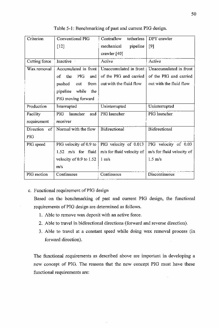
50
Table 5-1: Benchmarking of past and current PIG design.
Criterion Conventional PIG Contraflow tetherless DPT crawler
[12] mechanical pipeline
crawler [40]
[9]
Cutting force Inactive Active Active
Wax removal Accumulated in front Unaccumulated in front Unaccumulated in front
of the PIG and of the PIG and carried of the PIG and carried
pushed out from out with the fluid flow out with the fluid flow
pipeline while the
PIG moving forward
Production Interrupted Uninterrupted Uninterrupted
Facility PIG launcher and PIG launcher PIG launcher
requirement receiver
Direction of Normal with the flow Bidirectional Bidirectional
PIG
PIG speed PIG velocity of 0.9 to PIG velocity of 0.013 PIG velocity of 0.03
1.52 m/s for fluid m/s for fluid velocity of m/s for fluid velocity of
velocity of 0.9 to 1.52 1 m/s 1.5 m/s
m/s
PIG motion Continuous Continuous Discontinuous
c. Functional requirement of PIG design
Based on the benchmarking of past and current PIG design, the functional
requirements of PIG design are determined as follows.
1. Able to remove wax deposit with an active force.
2. Able to travel in bidirectional directions (forward and reverse direction).
3. Able to travel at a constant speed while doing wax removal process (in
forward direction).
The functional requirements as described above are important in developing a
new concept of PIG. The reasons that the new concept PIG must have these
functional requirements are:
51
1. During pigging operation, the PIG design removes wax deposit on the
pipeline wall by applying an active force. The use of active force during
wax removal makes amount of removed wax deposit that is removed from
pipeline still in a controllable value. As a consequences, the risk of wax
build up in front of the PIG which may cause the PIG get stuck inside the
pipeline is reduced [7].
2. The PIG is designed to be deployed from a platform at the surface and
travel against the flow. When the PIG reaches at the end of the pipeline, it
is desired to automatically return to the initial point of launching. It means
that the PIG design has a function to travel in bidirectional motion. The
PIG facility at the seabed can be eliminated with this function and results
on reducing capital expense of PIG facility [40].
3. Wax removal process is performed by the PIG design when it travels
against the fluid flow. It is required that the PIG design has a function to
maintain the speed while doing wax removal process. The cleaning
efficiency of wax deposit removal which is performed by PIG with this
function is same through the entire length of the pipeline [3].
In this research work, the scope of work is limited to identify features required
by the proposed PIG model and its general dimension.
d. PDS of PIG design
The functional requirements of PIG design are stated in measurable value at the
PDS document. This document states the performance of the PIG design that
should be achieved at the end of the process design. The PDS of the PIG design
is shown in Table 5-2. It is adopted from the PDS of contraflow tetherless
mechanical pipeline crawler [40].
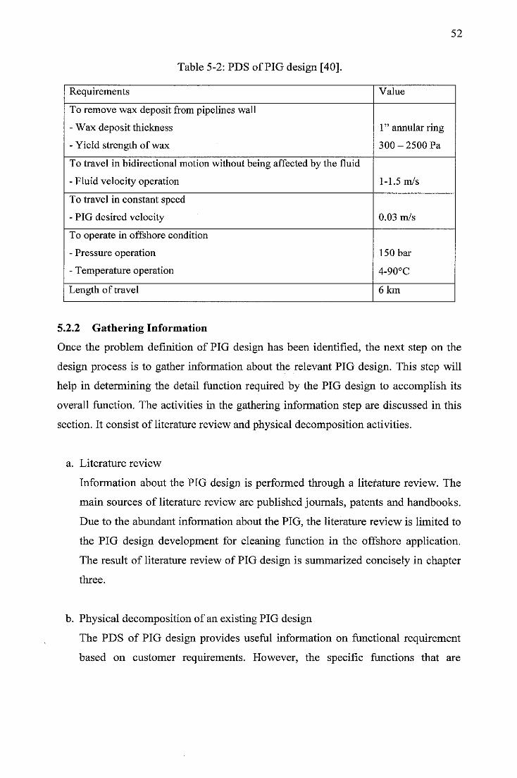
52
Table 5-2: PDS of PIG design [40].
Requirements Value
To remove wax deposit from pipelines wall
- Wax deposit thickness
- Yield strength of wax
1" annular ring
300-2500 Pa
To travel in bidirectional motion without being affected by the fluid
- Fluid velocity operation 1-1.5 m/s
To travel in constant speed
- PIG desired velocity 0.03 m/s
To operate in offshore condition
- Pressure operation
- Temperature operation
150 bar
4-90°C
Length of travel 6 km
5.2.2 Gathering Information
Once the problem definition of PIG design has been identified, the next step on the
design process is to gather information about the relevant PIG design. This step will
help in determining the detail function required by the PIG design to accomplish its
overall function. The activities in the gathering information step are discussed in this
section. It consist of literature review and physical decomposition activities.
a. Literature review
Information about the PIG design is performed through a literature review. The
main sources of literature review are published journals, patents and handbooks.
Due to the abundant information about the PIG, the literature review is limited to
the PIG design development for cleaning function in the offshore application.
The result of literature review of PIG design is summarized concisely in chapter
three.
b. Physical decomposition of an existing PIG design
The PDS of PIG design provides useful information on functional requirement
based on customer requirements. However, the specific functions that are
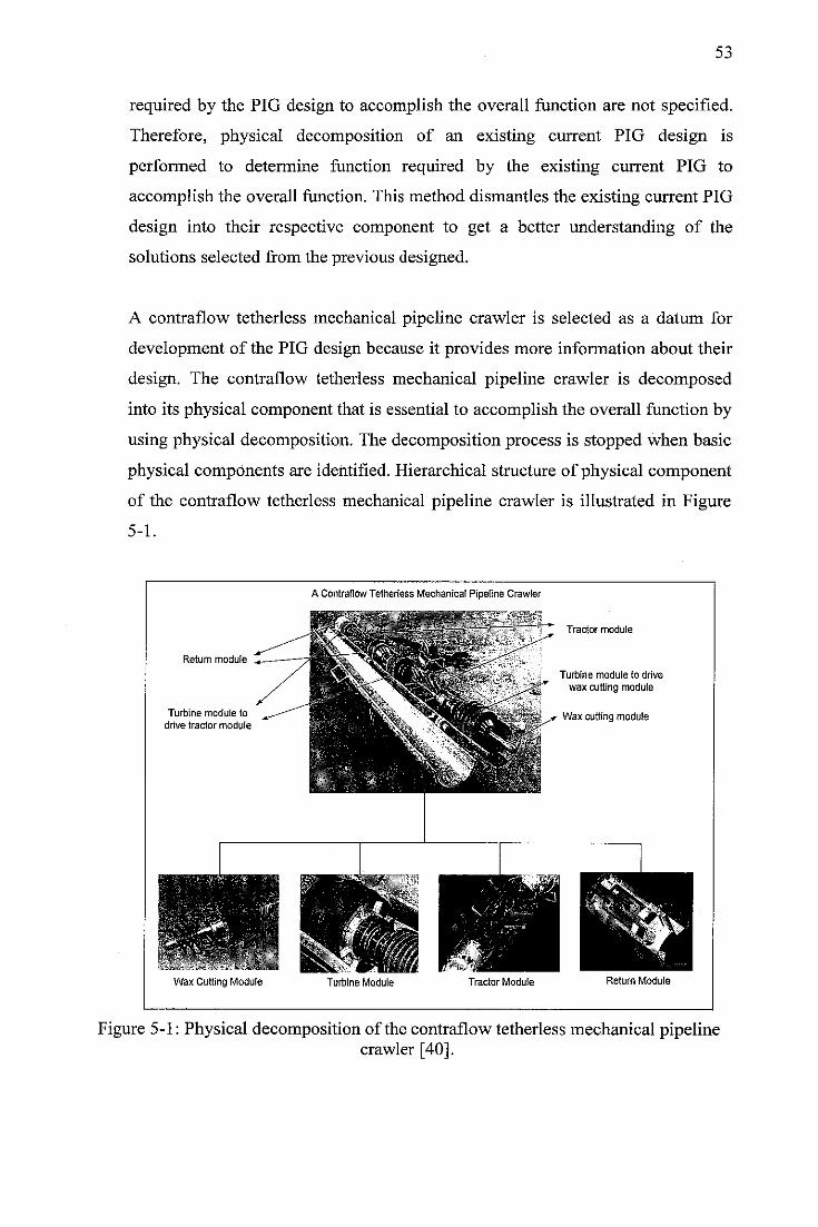
53
required by the PIG design to accomplish the overall function are not specified.
Therefore, physical decomposition of an existing current PIG design is
performed to determine function required by the existing current PIG to
accomplish the overall function. This method dismantles the existing current PIG
design into their respective component to get a better understanding of the
solutions selected from the previous designed.
A contraflow tetherless mechanical pipeline crawler is selected as a datum for
development of the PIG design because it provides more information about their
design. The contraflow tetherless mechanical pipeline crawler is decomposed
into its physical component that is essential to accomplish the overall function by
using physical decomposition. The decomposition process is stopped when basic
physical components are identified. Hierarchical structure of physical component
of the contraflow tetherless mechanical pipeline crawler is illustrated in Figure
5-1.
Return module
Turbine module to
drive tractor module
Wax Cutting Module
A Contraflow Tetherless Mechanical Pipeline Crawler
-'•-f. :._•••'
Turbine Module Tractor Module
Tractor module
Turbine module to drive
wax cutting module
Wax cutting module
Return Module
Figure 5-1: Physical decomposition of the contraflow tetherless mechanical pipelinecrawler [40].
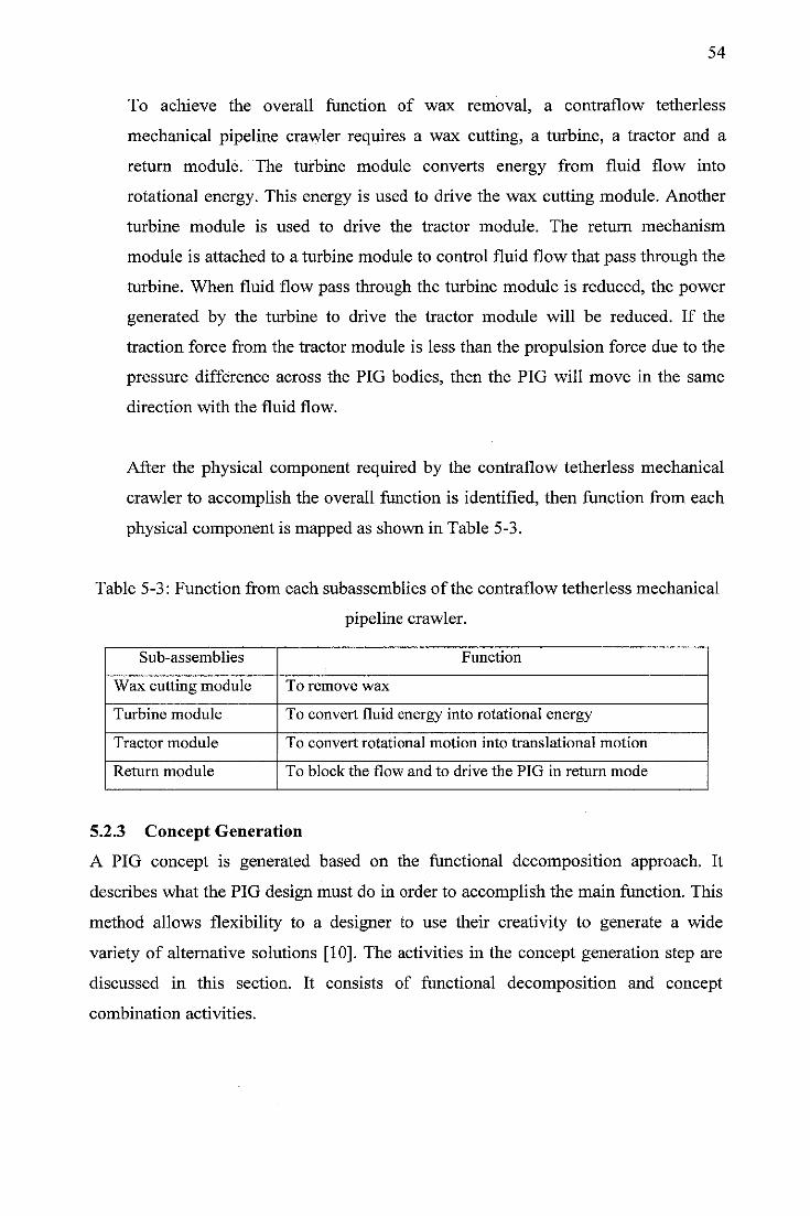
54
To achieve the overall function of wax removal, a contraflow tetherless
mechanical pipeline crawler requires a wax cutting, a turbine, a tractor and a
return module. The turbine module converts energy from fluid flow into
rotational energy. This energy is used to drive the wax cutting module. Another
turbine module is used to drive the tractor module. The return mechanism
module is attached to a turbine module to control fluid flow that pass through the
turbine. When fluid flow pass through the turbine module is reduced, the power
generated by the turbine to drive the tractor module will be reduced. If the
traction force from the tractor module is less than the propulsion force due to the
pressure difference across the PIG bodies, then the PIG will move in the same
direction with the fluid flow.
After the physical component required by the contraflow tetherless mechanical
crawler to accomplish the overall function is identified, then function from each
physical component is mapped as shown in Table 5-3.
Table 5-3: Function from each subassemblies of the contraflow tetherless mechanical
pipeline crawler.
Sub-assemblies Function
Wax cutting module To remove wax
Turbine module To convert fluid energy into rotational energy
Tractor module To convert rotational motion into translational motion
Return module To block the flow and to drive the PIG in return mode
5.2.3 Concept Generation
A PIG concept is generated based on the functional decomposition approach. It
describes what the PIG design must do in order to accomplish the main function. This
method allows flexibility to a designer to use their creativity to generate a wide
variety of alternative solutions [10]. The activities in the concept generation step are
discussed in this section. It consists of functional decomposition and concept
combination activities.
55
a. Functional decomposition
In order to achieve the main function of wax deposit removal, the PIG design
requires specific functions to carry out this task. Functional requirement of wax
removal with an active force, traveling in bidirectional motion and traveling at a
constant speed in forward direction as described in problem definition step is
used as a basis to determine functional requirements of PIG design. Functional
decomposition approach is used to further refine these functional requirements
into specific function required to accomplish the overall function of PIG design
[47].
In functional decomposition approach, the system function of a product design is
described as a transformation between an initial state and a desired state in terms
of either energy, material or information flow [48]. The benefit of using this
technique is to force a detailed understanding of what the product design is
supposed to do at the beginning of the design process.
The process of functional decomposition is started by decomposing the overall
function of product design into sub-functions expressed by a verb-noun
combination. The verb is used to indicate what is performed by a product design.
The noun is used to indicate the object on which the verb acts [47]. The list of
function verb that may help in determining the function of PIG design is shown
Table 5-4. Sub-functions result from functional decomposition is further ordered
to give a logical flow transformation in order to achieve the overall objective of
the product design. Finally, each sub-function is examined whether the
decomposition is enough or not. If not, a further decomposition of sub-
subfunctions is generated. The parameter to indicate enough functional
decomposition is when the function identified can be fulfilled by existing
objects.
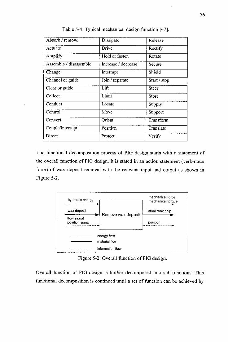
Table 5-4: Typical mechanical design function [47].
Absorb / remove Dissipate Release
Actuate Drive Rectify
Amplify Hold or fasten Rotate
Assemble / disassemble Increase / decrease Secure
Change Interrupt Shield
Channel or guide Join / separate Start / stop
Clear or guide Lift Steer
Collect Limit Store
Conduct Locate Supply
Control Move Support
Convert Orient Transform
Couple/interrupt Position Translate
Direct Protect Verify
56
The functional decomposition process of PIG design starts with a statement of
the overall function of PIG design. It is stated in an action statement (verb-noun
form) of wax deposit removal with the relevant input and output as shown in
Figure 5-2.
hydraulic energymechanical force,mechanical torque
Remove wax depositwax deposit small wax chip
flow signalposition signal
-•^
position
material flow
Figure 5-2: Overall function of PIG design.
Overall function of PIG design is further decomposed into sub-functions. This
functional decomposition is continued until a set of function can be achieved by
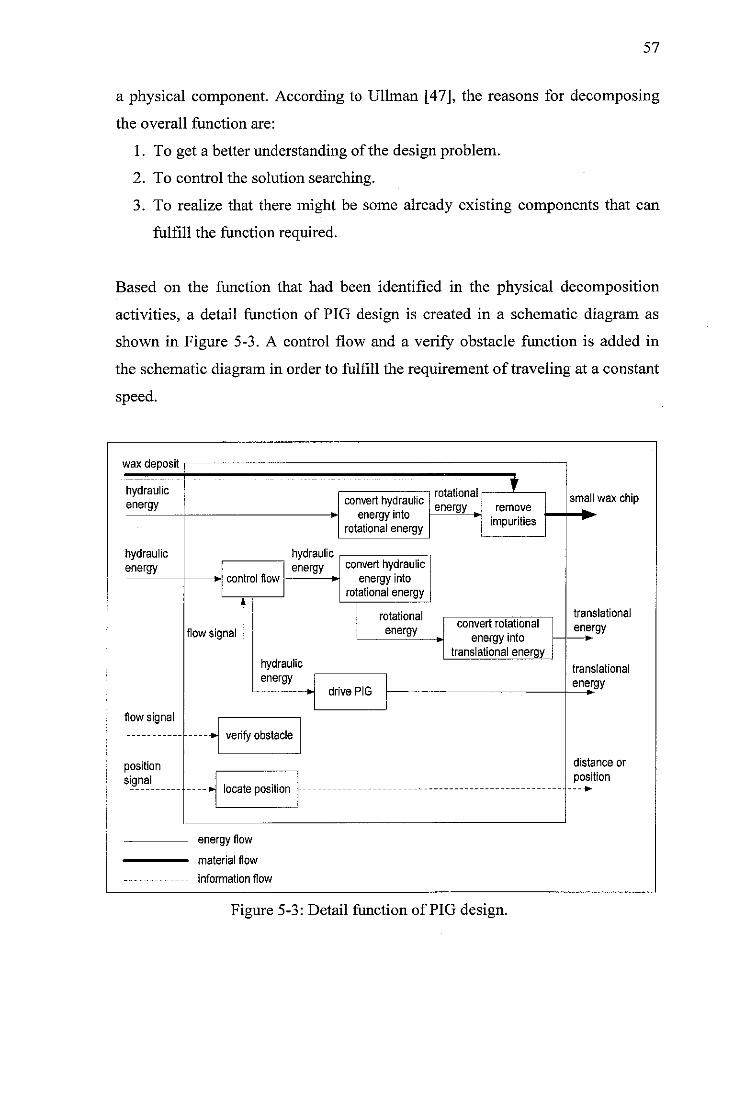
57
a physical component. According to Ullman [47], the reasons for decomposing
the overall function are:
1. To get a better understanding of the design problem.
2. To control the solution searching.
3. To realize that there might be some already existing components that can
fulfill the function required.
Based on the function that had been identified in the physical decomposition
activities, a detail function of PIG design is created in a schematic diagram as
shown in Figure 5-3. A control flow and a verify obstacle function is added in
the schematic diagram in order to fulfill the requirement of traveling at a constant
speed.
wax deposit
hydraulicenergy
hydraulicenergy
flowsignal
positionsignal
control flow
flowsignal
hydraulicenergy
convert hydraulicenergy into
rotational energy
convert hydraulicenergy into
rotational energy
rotational
energy
hydraulicenergy
drive PIG
verifyobstacle
locate position
energy flow
material flow
information flow
rotational
energy
1remove
impurities
convert rotational
energy intotranslational energy
Figure 5-3: Detail function of PIG design.
small wax chip
translational
energyK
translational
energy
distance or
position
58
Detail function of PIG design also represents the working principle of PIG
design. It is explained as follows.
1. Wax deposit removal function.
A hydraulic energy is converted into rotational energy by a device. This
rotational energy will be used by another device to break down wax deposit
into a small chip.
2. Traveling function
Hydraulic energy passes a device that controls the fluid flow. In counter
flow mode, hydraulic energy is converted into rotational energy by a
device. This rotational energy will be converted into translational energy by
another device to make the PIG design able to travel in a counter flow
direction. If the PIG travels in the undesired speed, a device that can verify
an obstacle will give a feedback to the control flow device. In case the PIG
travels faster than the desired speed, the flow control device will reduce the
amount of fluid pass over its. For the case the PIG travels very slowly and
out of the range from the designed, the control flow device will be fully
closed. As a consequence that hydraulic energy still flow, it will drive the
PIG through a device to make it automatically return to the initial point of
launching.
3. Safety function
Position of the PIG will be indicated by a device that can transmit and
receive the signal.
The detail function of PIG design helps to illustrate its working principle. It
provides a key step leading to the generation of large number of potential
solutions that can fulfill the required function of PIG design.
b. Morphological chart
The function required to carry out the overall function that had been identified in
the functional decomposition activities is put in a morphological chart. A
morphological chart is a visual way to capture the required function of PIG
design and to explore the solution for each required function. The solution for

59
each function is further explored as many as possible from patents, journal,
handbook and brainstorming. Once finished, the morphological chart contains a
complete range of all solutions for each function required to accomplish the
overall function of PIG design as shown in Table 5-5.
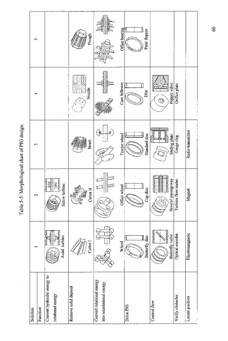
So
luti
on
Fu
ncti
on
Con
vert
hydr
aulic
ener
gyto
rota
tion
alen
ergy
Rem
ove
solid
depo
sit
Con
vert
rota
tion
alen
ergy
into
tran
slat
iona
len
ergy
Dri
ve
PIG
Co
ntr
ol
flo
w
Ver
ify
obst
acle
s
Loc
ate
posi
tion
•A-r
7-/
-rA
vrw
Tr.
Ax
ial
turb
ine
Cu
tter
I
Wh
eel
But
terf
lydi
sc
TT
TU
TU
m
But
terf
lyva
lve
Opt
ical
enco
der
Ele
ctro
mag
neti
c
Tab
le5-
5:M
orph
olog
ical
char
to
fPIG
desi
gn.
-UM
I
Scre
wtu
rbin
e
M^
-m
m
Cu
tter
IIB
rush
No
zzle
Plo
ugh
R^
~
rrM
M/f/
p'rh
!fe_
Off
set
wh
eel
Tra
cto
rw
heel
Cam
foll
ow
erO
ffse
tbea
ring
Cup
disc
Sta
nd
ard
dis
cD
isc
Peta
lfla
pper
J<
Seve
ral
pass
agew
ayS
lidi
ngpl
ate
Popp
etva
lve
Tu
rbin
efl
ow
mete
rG
auge
ring
Ori
fice
plat
e
Mag
net
Rad
iotr
an
smit
ter
60
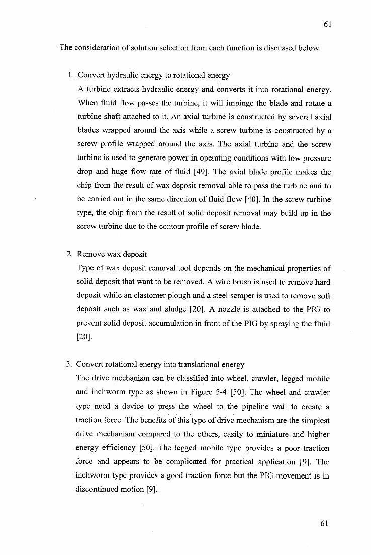
61
The consideration of solution selection from each function is discussed below.
1. Convert hydraulic energy to rotational energy
A turbine extracts hydraulic energy and converts it into rotational energy.
When fluid flow passes the turbine, it will impinge the blade and rotate a
turbine shaft attached to it. An axial turbine is constructed by several axial
blades wrapped around the axis while a screw turbine is constructed by a
screw profile wrapped around the axis. The axial turbine and the screw
turbine is used to generate power in operating conditions with low pressure
drop and huge flow rate of fluid [49]. The axial blade profile makes the
chip from the result of wax deposit removal able to pass the turbine and to
be carried out in the same direction of fluid flow [40]. In the screw turbine
type, the chip from the result of solid deposit removal may build up in the
screw turbine due to the contour profile of screw blade.
2. Remove wax deposit
Type of wax deposit removal tool depends on the mechanical properties of
solid deposit that want to be removed. A wire brush is used to remove hard
deposit while an elastomer plough and a steel scraper is used to remove soft
deposit such as wax and sludge [20]. A nozzle is attached to the PIG to
prevent solid deposit accumulation in front of the PIG by spraying the fluid
[20].
3. Convert rotational energy into translational energy
The drive mechanism can be classified into wheel, crawler, legged mobile
and inchworm type as shown in Figure 5-4 [50]. The wheel and crawler
type need a device to press the wheel to the pipeline wall to create a
traction force. The benefits of this type of drive mechanism are the simplest
drive mechanism compared to the others, easily to miniature and higher
energy efficiency [50]. The legged mobile type provides a poor traction
force and appears to be complicated for practical application [9]. The
inchworm type provides a good traction force but the PIG movement is in
discontinued motion [9].
61
62
Figure 5-4: Classification of drive mechanism [50].
4. Drive PIG
A conventional PIG utilizes fluid source through the disc as a propulsion
force. The pressure difference across the disc forces the PIG to move in the
same direction with the fluid flow. Disc types can be classified into
butterfly, cup, standard, petal flapper, and disc. The advantages and
drawbacks of each disc type are discussed below,
i. Butterfly disc
The butterfly disc is made by removing some material to overcome
hoop stress when it enters the smaller pipeline. The sealing
performance is not satisfactory but can be improved by adding a thin
membrane behind the butterfly disc [30].
ii. Cup
The cup disc provides a better sealing performance and able to pass
obstruction until twenty percent of the pipeline diameter [20].
iii. Standard disc
The standard disc is known as the least expensive [20].
iv. Petal flapper
The petal flapper comprises of a set of individual disc which overlaps
to form a seal. It is more efficient than the butterfly disc but still
unformed an adequate sealing [30].
v. Disc
The disc is able to use in a reverse direction and very effective for
sealing function [51].
63
5. Control flow
The PIG speed can be regulatedby controlling the volume flow rate of fluid
that passes through a turbine. A flow control device is attached to the
turbine to make the PIG travel in a constant speed. When the PIG travels
faster than the desired speed, the valve opening will be smaller than normal
condition. The type of flow control device can be classified into butterfly
valve, passage way, sliding plate, and poppet valve. The advantages and
drawbacks of each type of flow control device are described as following,
i. Butterfly valve
A butterfly valve is used to control the volume flow rate of fluid across
the PIG bodies. It is driven by an internal motor with an internal
battery as a power source. The advantages of this device are simple to
implement and a good throttle device [28].
ii. Several passage way
Several passage way device consists of several tubes that pass through
the PIG bodies and an end plate that is moved relative to the PIG
bodies [52]. The relative movement between the end plate and PIG
bodies regulates the volume flow rate of fluid through the PIG bodies.
An internal motor with an internal battery as a power source is used to
drive the end plate that moves relative to the PIG bodies,
iii. Sliding plate
A sliding plate device consists of a sleeve valve that slides through the
bypass duct to regulate the fluid flow. A hydraulic or an electrical
actuator is used to drive the sleeve valve across the duct. This device is
suitable for an application in huge volume flow rate of the fluid
operation [53].
iv. Poppet valve
The volume flow rate of fluid across the PIG bodies can be controlled
by using a poppet valve that consists of a cone valve and a spring. An
opening valve is determined by the spring stiffness. This system does
not depend on the internal power source [54].
64
6. Verify obstacles
A sensor is used to determine whether a PIG travels at constant speed or
not. A controller receives a feedback from this sensor and gives an order to
an actuator to regulate an opening valve. The type of device that can be
used to verify obstacles are turbine flowmeter, orifice plate, optical
encoder, and gauge ring. The advantages and drawbacks of each type of
this sensor are discussed below.
i. Turbine flowmeter
The fluid flow that passes through a turbine can be used indirectly to
indicate the PIG speed. When the fluid flow passes through the turbine
flowmeter larger than a setting point, it means the PIG travels faster
than the desired value. The drawback of turbine flowmeter sensor is
unsuitable for application in abrasive fluid [55].
ii. Orifice plate
An orifice plate is used to measure indirectly the PIG speed by
comparing the measurement value of fluid velocity to a setting point of
PIG speed. It has advantage on the least expensive. The drawback of
the orifice plate is limitation ofthe range measurement [55].
iii. Optical encoder
A rotational shaft speed of turbine can be used indirectly to indicate the
PIG speed. An optical encoder is used to measure the turbine rotational
shaft speed. It has advantages on simple, reliable and low cost solution
[55].
iv. Gauge ring
A tactile sensor like gauge ring can be used to measure force act on the
PIG. It can be used to indicate whether the PIG can pass an obstruction
or not. The advantage of gauge ring is simple and compact.
7. Locate position
PIG locating is a method to determinethe position of PIG in the pipeline. A
transmitter device is carried by the PIG while a receiver is put along the
pipeline to locate the PIG. The devices that can be used to locate the PIG
position are electromagnetic, magnet and radio transmitter. The strong
points and drawbacks from each device are discussed below.
65
i. Electromagnetic
An electromagnetic device is mounted in a PIG. This device transmits
an electrical magnetic field. The electrical magnetic field will be
received by a receiver located in the ship that operates near the
operation pipelines. This system generally has a range area of one until
three meter for the offshore application [20].
ii. Magnet
A small permanent is attached in a PIG. When the PIG passes a marker
that is laid on the pipeline, the magnet field will turn on the marker.
The advantage of this device is independent on an internal power
source which may exhaust during the pigging process. The drawback
of this device is the range of operation limited up to two meters below
the ground [20],
iii. Acoustic pinger
An acoustic pinger is a battery-powered acoustic beacon which emits
an acoustic pulse at regular time and particular frequency. This device
has a range area up to two km and accuracy in a range between five
and ten meter [56]. The drawback of this device is that it is not suitable
for gas pipeline and dual layer pipeline [57].
c. Concept combination
Generating conceptual design of PIG is performed by selecting solution for each
function and combining them to form concepts. If all the solution from each
function from the morphological chart of PIG design at Table 5-4 is combined, it
will produce around 12000 concept of PIG design.
During the combination process, several criteria are considered to produce
potential concepts design of PIG. The criteria used are combination of solution
that would demonstrate ability to move in bidirectional motion at a constant
speed, rank of the possible solution factor and compatibility factor [58]. Based
on these criteria, several PIG concepts are generated. A schematic drawing of
each concept design of PIG is then created to visualize each individual concept
as shown in Table 5-6.
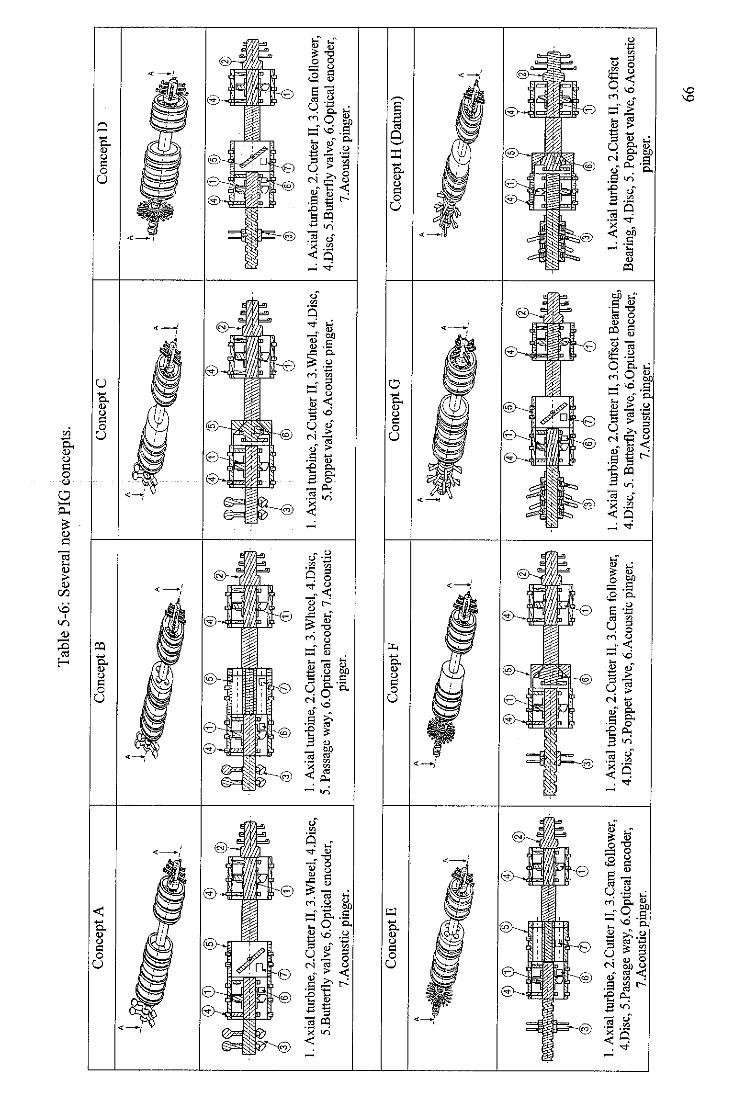
Con
cept
A
1.A
xial
turb
ine,
2.C
utte
rII
,3.W
heel
,4.D
isc,
5.B
utte
rfly
valv
e,6.
Opt
ical
enco
der,
^__
_7.
Aco
ustic
ping
er.
Con
cept
E
1.A
xial
turb
ine,
2.C
utte
rII
,3.C
amfo
llow
er,
4.D
isc,
5.Pa
ssag
ew
ay,6
.0pt
ical
enco
der,
7.A
cous
ticpi
nger
.
Tab
le5-
6:Se
vera
lnew
PIG
conc
epts
.
Con
cept
B
1.A
xial
turb
ine,
2.C
utte
rII
,3.W
heel
,4.
Dis
c,5.
Pass
age
way
,6.0
ptic
alen
code
r,7.
Aco
ustic
ping
er.
Con
cept
F
1.A
xial
turb
ine,
2.C
utte
rII
,3.C
amfo
llow
er,
4.D
isc,
5.Po
ppet
valv
e,6.
Aco
ustic
ping
er.
Con
cept
C
1.A
xial
turb
ine,
2.C
utte
rII,
3.W
heel
,4.D
isc,
5.P
oppe
tval
ve,
6.A
cous
ticpi
nger
.
Con
cept
G
1.A
xial
turb
ine,
2.C
utte
rII
,3.0
ffse
tBea
ring,
4.D
isc,
5.B
utte
rfly
valv
e,6.
0ptic
alen
code
r,7.
Aco
ustic
ping
er.
Con
cept
D
©<J)
©
1.A
xial
turb
ine,
2.C
utte
rII,
3.C
amfo
llow
er,
4.D
isc,
5.B
utte
rfly
valv
e,6.
0pti
cale
ncod
er,
7.A
cous
ticpi
nger
.
Con
cept
H(D
atum
)
1.A
xial
turb
ine,
2.C
urte
rII,
3.0f
fset
Bea
ring
,4.D
isc,
5.Po
ppet
valv
e,6.
Aco
ustic
ping
er.
66
67
The working principle for each concept is explained as follows.
1. Concept A
Concept A consists of an axial turbine with function of converting
hydraulic energy into rotational energy, a cutter with function of wax
deposit removal, a butterfly valve with function of regulating the volume
flow rate of fluid through the axial turbine, an offset wheel with function as
a drive mechanism, an optical encoder with function of sensing the
obstruction of fluid velocity change and an acoustic pinger with function of
locating the PIG.
One turbine is used to rotate a cutter tool and the other is used to drive a
drive mechanism of offset wheel. The turbine for drive mechanism is
attached with the butterfly valve which is driven by an internal motor with
an internal battery as a power source. The optical encoder is used to
measure the rotational speed of turbine shaft which represents the PIG
speed. Based on this input, the butterfly valve is driven by the internal
motor to open or close partially.
The PIG can move in a counter flow direction because the wheel axis is not
perpendicular to the pipeline axis. When driven by the turbine, a torque is
applied to the drive mechanism shaft, the wheel moves in a forward
direction and makes a spiral motion like a screw. In case drive mechanism
is incapable to provide enough traction force to move in the counter flow
direction, the butterfly valve will be fully closed. Since fluid flow keeps
flowing, the PIG is forced to return to the initial point of launching.
2. Concept B
Concept B is the same with concept A. The difference is a device that is
used to regulate the volume flow rate of fluid through the axial turbine is a
several passage way mechanism. It consists of an end plate at the front
passage way mechanism which can block the fluid flow. The end plate is
driven by an internal motor with an internal battery as a power source.
68
3. Concept C
Concept C is the same with concept A. The difference is a device that is
used to regulate the volume flow rate of fluid through the axial turbine is a
poppet valve mechanism. This poppet valve mechanism is a perpetual
mechanism where the volume flow rate of fluid through this valve depends
on the spring stiffness.
4. Concept D
Concept D consists of an axial turbine with function of converting
hydraulic energy into rotational energy, a cutter with function of wax
deposit removal, a butterfly valve with function of regulating the volume
flow rate of fluid through an axial turbine, an cam follower with function as
a drive mechanism, an optical encoder with function of sensing an
obstruction of fluid velocity change and an acoustic pinger with function of
locating the PIG.
One turbine is used to rotate the cutter tool and the other is used to drive the
drive mechanism of cam follower. The turbine for drive mechanism is
attached with the butterfly valve which is driven by an internal motor with
an internal battery as a power source. The optical encoder is measured the
rotational speed of turbine shaft which represents the PIG speed. Based on
this input, the butterfly valve is driven by the internal motor to open or
close partially.
The PIG can move in a forward direction because of the unique
characteristic of the bristle which is easier to move in a forward rather than
in a backward direction. As the drive mechanism shaft rotates, the bristle
slides along the traverse shaft until it reaches at the end of the shaft. When
the bristle reaches at the end of the shaft, it will move continuously in the
backward direction. By taking the advantage of the bristle which is easier to
move in the forward direction rather than in the backward direction, the
bristle will grip the pipeline and the PIG will move in the forward direction.
This sequential step of the drive mechanism is repeated continuously to
make the PIG able to crawl in the forward direction. When the fluid flow is
69
incapable to be converted into the traction force required to move in the
counter flow direction, the butterfly valve will close and block the path of
fluid flow. At this condition, the PIG will act like a conventional PIG. The
fluid flow will push the PIG to return to the initial point of launching.
5. Concept E
Concept E is the same with concept D. The difference is a device that is
used to regulate the volume flow rate of fluid through the axial turbine is a
several passage way mechanism. It consists of an end plate at the front of
passage way mechanism which can block the volume flow rate of fluid.
The end plate is driven by an internal motor with an internal battery as a
power source.
6. Concept F
Concept F is the same with concept D. The difference is a device that is
used to regulate the volume flow rate of fluid through an axial turbine is a
poppet valve mechanism. This poppet valve mechanism is a perpetual
mechanism where the volume flow rate of fluid through this valve depends
on the spring stiffness.
7. Concept G
Concept G consists of an axial turbine with function of converting
hydraulic energy into rotational energy, a cutter with function of wax
deposit removal, a butterfly valve with function of regulating the volume
flow rate of fluid through the axial turbine, an offset bearing with function
as a drive mechanism, an optical encoder with function of sensing an
obstruction of fluid velocity change and an acoustic pinger with function of
locating the PIG.
One turbine is used to rotate the cutter tool and the other is used to drive the
drive mechanism of the offset bearings. The turbine for a drive mechanism
is attached to a butterfly valve which is driven by an internal motor with an
internal battery as a power source. The optical encoder is measured the
rotational speed of turbine shaft which represents the PIG speed. Based on
70
this input, the butterfly valve is driven by the internal motor to open or
close partially.
The PIG can move in a counter flow direction because of the oscillatory
motion of outward, backward, inward and forward from a set of legs. The
legs are mounted to the bearing where the axis of this bearing is offset from
the axis of the drive mechanism shaft. The bearing moves forward towards
the centreline of the drive mechanism shaft when the shaft of the drive
mechanism rotates. It makes the leg mounted on the offset bearing at a
particular time to touch the pipeline wall to create a traction force. By
ordering the sequence of the legs to touch the pipeline wall, the PIG will be
able to travel in a counter flow direction like a human walking mechanism.
In case the fluid flow is incapable to be converted into the traction force
required to drive the PIG in the counter flow direction, the butterfly valve
will close. As a consequence, the PIG will be pushed by the fluid flow to
return to the initial point of launching.
8. Concept H
Concept H is the same with concept G. The difference is a device that is
used to regulate the volume flow rate of fluid through an axial turbine is a
poppet valve mechanism. This poppet valve mechanism is a perpetual
mechanism where the fluid flow through this valve depends on the spring
stiffness.
Concept H is almost similar with the contraflow tetherless mechanical
pipeline crawler that has been produced by Astec Development Ltd. for the
Shell. Therefore, in the concept evaluation step, it is chosen as a datum to
represent a commercial PIG that has been produced in the market.
5.2.4 Concept Evaluation
Once the design concepts of PIG have been generated, concept evaluation is to be
done to select the most promising to be further developed in the embodiment design
phase. This is performed in the concept evaluation step. Each concept is compared to
each other for particular criteria to find its strength and weakness. The method that is
71
used to select the most promising concept in this design process is concept screening[46].
In the concept screening method, each design concept is compared to each other for
particular criteria with the equal weight. The criteria that are used to select the most
promising concept of PIG are: able to travel at uniform speed, ease of traveling in
forward and reverse direction, reliability, ease of manufacture, duration of operation
and robustness. These criteria are derived based on the PDS of PIG design and related
references [47, 59]. A concept screening matrix evaluation form is further generated
based on these criteria.
In order to select the most promising concept of PIG, a survey was performed to
solicit feedback from peer reviewers. Initially, the survey forms were sent through the
academic people in Universiti Teknologi ofPETRONAS, Malaysia, pigging company
and pipeline operator. The reviewers from the academic people consist of four
lecturers and two PhD. students, who have a background in the mechanical design to
represent feedback from education point of view. Meanwhile, the pigging companies
that had been sent the survey form are Rosen Inspection Far East, Weatherford,
Romstar, BJ Oilwell Service and Aker Kaverner Sdn Bhd. Pipeline operators that
were sent are Petronas Penapisan Sdn Bhd, Kerteh, Trenganu and Petronas Carigali
Sdn Bhd. The reviewers who send back the survey were from academic people and
Petronas Penapisan Sdn Bhd. An example of survey form of concept evaluation
matrix is attached in Appendix A. The ranking of each concept is based on the result
of survey as shown in Table 5-7. Further, score weight factor is used to determine the
most promising concept of PIG.
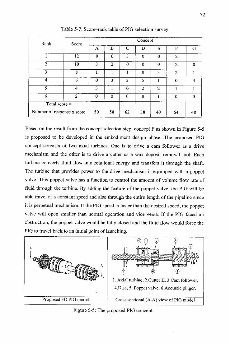
72
Table 5-7: Score-rank table of PIG selection survey.
Rank ScoreConcept
A B C D E F G
1 12 0 0 3 0 0 2 1
2 10 3 2 0 0 0 2 0
3 8 1 1 1 0 3 2 1
4 6 0 3 3 5 1 0 4
5 4 3 1 0 2 2 1 1
6 2 0 0 0 0 1 0 0
Total score =
Number of response x score 50 50 62 38 40 64 48
Based on the result from the concept selection step, concept F as shown in Figure 5-5
is proposed to be developed in the embodiment design phase. The proposed PIG
concept consists of two axial turbines. One is to drive a cam follower as a drive
mechanism and the other is to drive a cutter as a wax deposit removal tool. Each
turbine converts fluid flow into rotational energy and transfers it through the shaft.
The turbine that provides power to the drive mechanism is equipped with a poppet
valve. This poppet valve has a function to control the amount of volume flow rate of
fluid through the turbine. By adding the feature of the poppet valve, the PIG will be
able travel at a constant speed and also through the entire length of the pipeline since
it is perpetual mechanism. If the PIG speed is faster than the desired speed, the poppet
valve will open smaller than normal operation and vice versa. If the PIG faced an
obstruction, the poppet valve would be fully closed and the fluid flow would force the
PIG to travel back to an initial point of launching.
Proposed 3D PIG model
© (1'
1. Axial turbine, 2.Cutter II, 3,Cam follower,
4.Disc, 5. Poppet valve, 6.Acoustic pinger.
Cross sectional (A-A) view of PIG model
Figure 5-5; The proposed PIG concept.
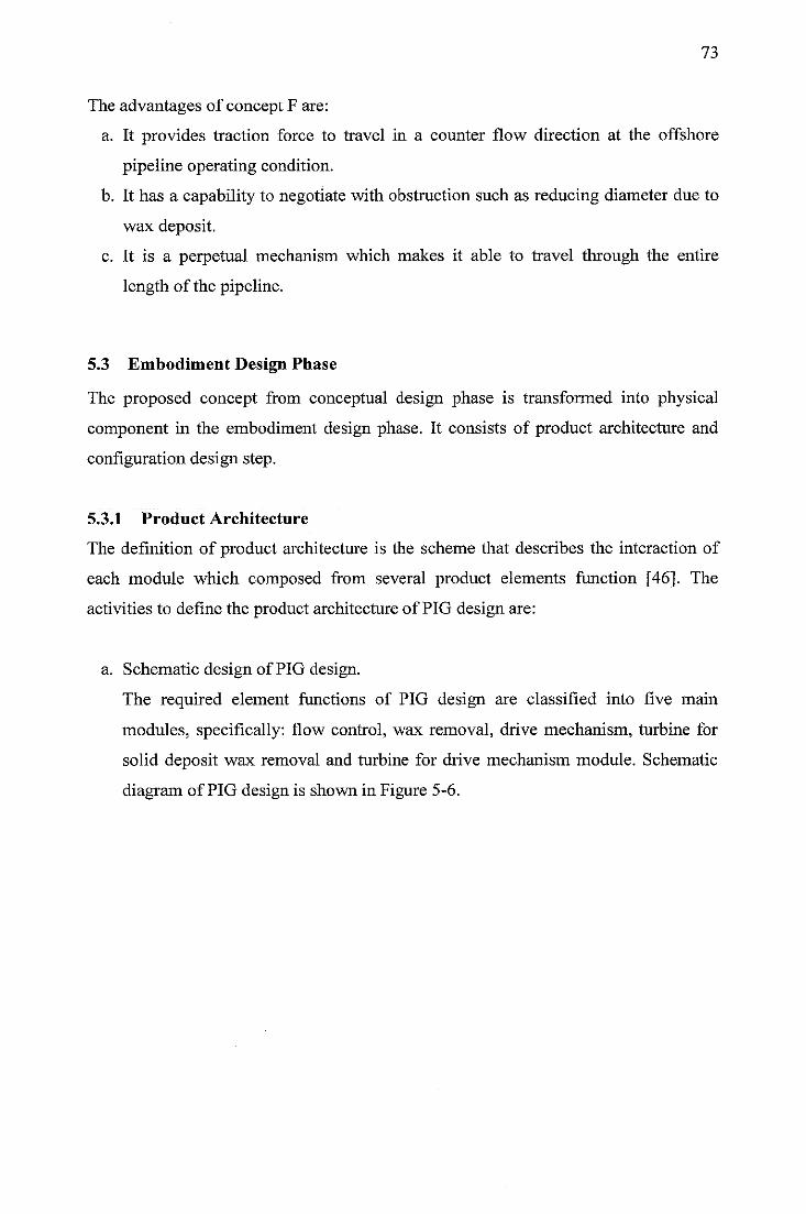
73
The advantages of concept F are:
a. It provides traction force to travel in a counter flow direction at the offshore
pipeline operating condition.
b. It has a capability to negotiate with obstruction such as reducing diameter due to
wax deposit.
c. It is a perpetual mechanism which makes it able to travel through the entire
length of the pipeline.
5.3 Embodiment Design Phase
The proposed concept from conceptual design phase is transformed into physical
component in the embodiment design phase. It consists of product architecture and
configuration design step.
5.3.1 Product Architecture
The definition of product architecture is the scheme that describes the interaction of
each module which composed from several product elements function [46]. The
activities to define the product architecture of PIG design are:
a. Schematic design of PIG design.
The required element functions of PIG design are classified into five main
modules, specifically: flow control, wax removal, drive mechanism, turbine for
solid deposit wax removal and turbine for drive mechanism module. Schematic
diagram of PIG design is shown in Figure 5-6.
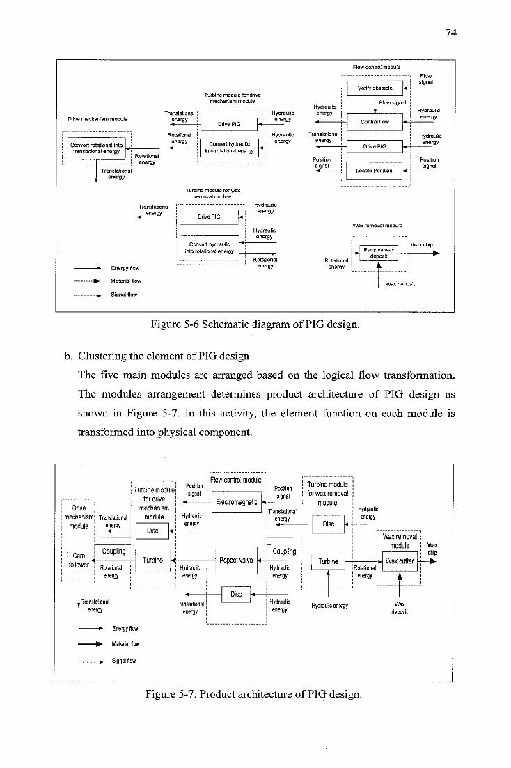
Drive mechanism module
Convert rotational intotranslational energy
Rotational
energy
Translationalenergy
Translational
energy
Rotational
energy
Turbine module far drive
mechanism module
Convert hydraulic
into rotational energy
Turbine module for waxremoval module
Hydraulicenergy
Hydraulicenergy
Translational
energy
Hydraulicenergy
—»- Energy flow
-•- Material flow
---». Signal flow
Convert hydraulic
into rotational energy
Hydraulicenergy
Rotational
energy
Flow control module
Flow
Verify obstacle *
Hydraulic ',energy |
I Row signal
V Hydraulic
Control flow <-
energy
Translational ! Hydraulic
Drive PIG •«-energy
i
Position ! Position
signal im ;- Locate Position
signal
Wax removal module
-•-
; Wax chipRemove wax
depositRotational
energy 1 L
Wax deposit
74
Figure 5-6 Schematic diagram of PIG design.
b. Clustering the element of PIG design
The five main modules are arranged based on the logical flow transformation.
The modules arrangement determines product architecture of PIG design as
shown in Figure 5-7. In this activity, the element function on each module is
transformed into physical component.
Drive
mechanism:
module
Cam
follower
Translational
energy
Coupling
Rotational
energy
Turbine module!
for drive
mechanism
module
Disc
Turbine
Hydraulicenergy
Hydraulicenergy
Translational
energy
—• Energy flow
• Material flow
>. Signalflow
Translational
energy
Flow control modulePosition
signal
* +- Electromagnetic
Poppet valve
Disc
Position
signal
!Translationalenergy
Coupling
Hydraulicenergy
Hydraulicenergy
Turbine module
for wax removal
module
Disc
Turbine
Hydraulic energy
Hydraulicenergy
Wax removal
module
iRotationali
energy
Wax cutter
Wax
deposit
Figure 5-7: Product architecture of PIG design.
wax
chip
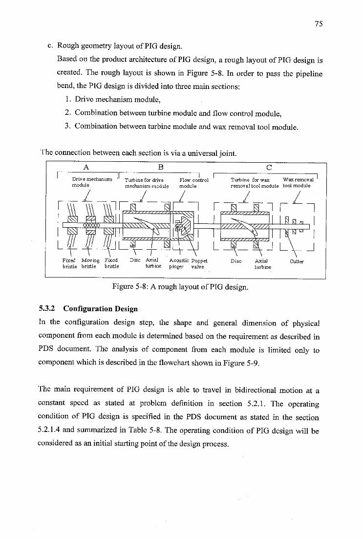
75
c. Rough geometry layout of PIG design.
Based on the product architecture of PIG design, a rough layout of PIG design is
created. The rough layout is shown in Figure 5-8. In order to pass the pipeline
bend, the PIG design is divided into three main sections:
1. Drive mechanism module,
2. Combination between turbine module and flow control module,
3. Combination between turbine module and wax removal tool module.
The connectionbetween each section is via a universaljoint.
A B
Drive mechanism Turbine for drive Flow controlmodule mechanism module module
C
Turbine for wax Wax removal
removal tool module tool module
r~i r h„ wj r \
Fixed Moving Fixed Disc Axial Acoustic Poppetbristle bristle bristle turbine pinger valve
Disc Axial
turb ine
Figure 5-8: A rough layout of PIG design.
5.3.2 Configuration Design
In the configuration design step, the shape and general dimension of physical
component from each module is determined based on the requirement as described in
PDS document. The analysis of component from each module is limited only to
component which is described in the flowchart shown in Figure 5-9.
The main requirement of PIG design is able to travel in bidirectional motion at a
constant speed as stated at problem definition in section 5.2.1. The operating
condition of PIG design is specified in the PDS document as stated in the section
5.2.1.4 and summarized in Table 5-8. The operating condition of PIG design will be
considered as an initial starting point of the design process.
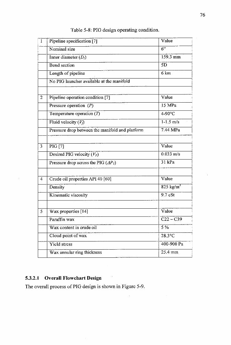
Table 5-8: PIG design operating condition.
1 Pipeline specification [7] Value
Nominal size 6"
Inner diameter (D/) 159.3 mm
Bend section 5D
Length of pipeline 6 km
No PIG launcher available at the manifold
2 Pipeline operation condition [7] Value
Pressure operation (P) 15 MPa
Temperature operation (7) 4-90°C
Fluid velocity (VJ) 1-1.5 m/s
Pressure drop between the manifold and platform 7.44 MPa
3 PIG [71 Value
Desired PIG velocity (VP) 0.033 m/s
Pressure drop across the PIG (APT) 31 kPa
4 Crude oil properties API 40 [60] Value
Density 825 kg/mJ
Kinematic viscosity 9.7 cSt
5 Wax properties [14] Value
Paraffin wax C22 - C39
Wax content in crude oil 5%
Cloud point of wax 28.3°C
Yield stress 400-900 Pa
Wax annular ring thickness 25.4 mm
5.3.2.1 Overall Flowchart Design
The overall process of PIG design is shown in Figure 5-9.
76
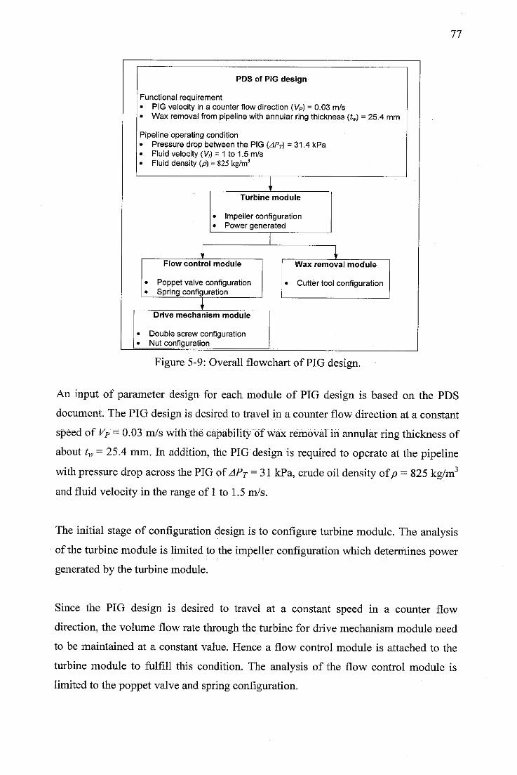
PDS of PIG design
Functional requirement• PIG velocity in a counter flow direction (VP) = 0.03 m/s• Wax removal from pipeline with annular ring thickness (tw) = 25.4 mm
Pipeline operating condition• Pressure drop between the PIG (APT) = 31.4 kPa• Fluid velocity (V» = 1 to 1.5 m/s• Fluiddensity (p)= 825kg/m3
Turbine module
Impeller configurationPower generated
Flow control module
Poppet valve configurationSpring configuration
Drive mechanism module
Double screw configurationNut configuration
Wax removal module
Cutter tool configuration
77
Figure 5-9: Overall flowchart of PIG design.
An input of parameter design for each module of PIG design is based on the PDS
document. The PIG design is desired to travel in a counter flow direction at a constant
speed of VP = 0.03 m/s with the capability of wax removal in annular ring thickness of
about tw = 25.4 mm. In addition, the PIG design is required to operate at the pipeline
with pressure drop across thePIG of APT = 31 kPa, crude oil density ofp = 825 kg/m3
and fluid velocity in the range of 1 to 1.5 m/s.
The initial stage of configuration design is to configure turbine module. The analysis
of the turbine module is limitedto the impellerconfiguration which determines power
generated by the turbine module.
Since the PIG design is desired to travel at a constant speed in a counter flow
direction, the volume flow rate through the turbine for drive mechanism module need
to be maintained at a constant value. Hence a flow control module is attached to the
turbine module to fulfill this condition. The analysis of the flow control module is
limited to the poppet valve and spring configuration.
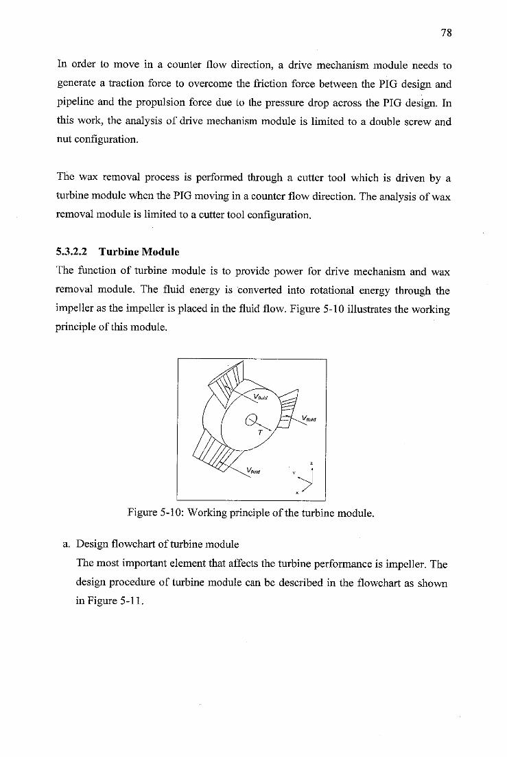
78
In order to move in a counter flow direction, a drive mechanism module needs to
generate a traction force to overcome the friction force between the PIG design and
pipeline and the propulsion force due to the pressure drop across the PIG design. In
this work, the analysis of drive mechanism module is limited to a double screw and
nut configuration.
The wax removal process is performed through a cutter tool which is driven by a
turbine module when the PIG moving in a counter flow direction. The analysis of wax
removal module is limited to a cutter tool configuration.
5.3.2.2 Turbine Module
The function of turbine module is to provide power for drive mechanism and wax
removal module. The fluid energy is converted into rotational energy through the
impeller as the impeller is placed in the fluid flow. Figure 5-10 illustrates the working
principle of this module.
Figure 5-10: Working principle of the turbine module.
a. Design flowchart of turbine module
The most important element that affects the turbine performance is impeller. The
design procedure of turbine module can be described in the flowchart as shown
in Figure 5-11.
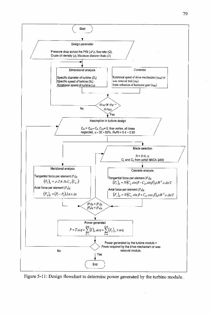
Start
Design parameter
Pressure dropacross the PIG (APT\ flow rate (Q),Crude oil density (p), Maximum diameter blade (£>)
Dimensional analysis
Specific diameter of turbine (0S)Specificspeed ofturbine (Ns)Rotational speed of turbine (w)
No
Constraint
Rotational speedofdrivemechanism (<onw) orwax removal tool {aw)Ratio reduction ofharmonic gear {uhg)
Assumption inturbinedesign
Cm - CA2= Cfl. Cu2= 0, free vortex, all losesneglected, ij= 30 - 60%, Rh/Rt = 0.4 ~ 0.55
Meridional analysis
Tangential force per element [Ft)e
(FT)E=p.2.x.Az.CA(Cv)Axial force per element {FA)E
(FA)E=(P>-P2\2.x.r.Az
Blade selection
/V=3~5, c,CL and CD from airfoil NACA 2409
Cascade analysis
Tangential force per element {FT)E
(FT)g =N.[CL.cos/1-CD.smfi}.pW2 .c.Az/2
Axial force per element [FA)E
(fa )E =n(cl•sin P+cd- cos J3).pW2 .cJz/2
Power generated
P=T.<o.n =fj(T)EMr} =fj(FT)E.r.oy.nE=a E=a
No
End
Power generated by the turbine module >Power required by the drive mechanism or wax
removal module.
79
Figure 5-11: Design flowchart to determinepower generated by the turbine module.
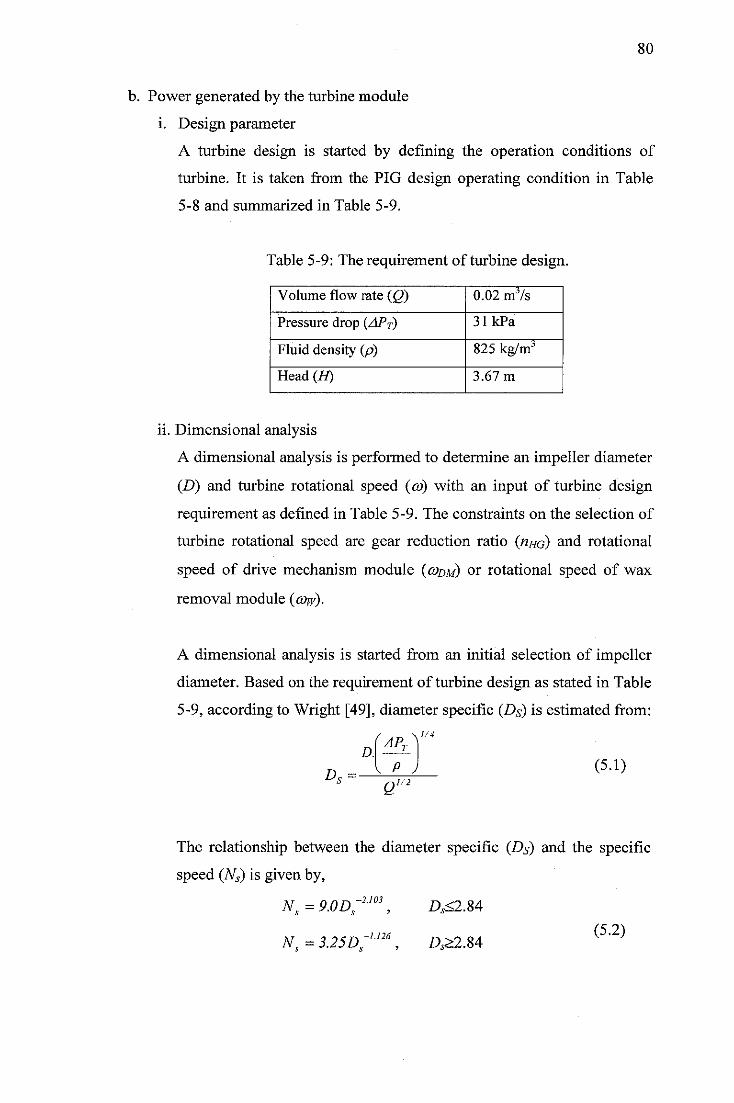
80
b. Power generated by the turbine module
i. Design parameter
A turbine design is started by defining the operation conditions of
turbine. It is taken from the PIG design operating condition in Table
5-8 and summarized in Table 5-9.
Table 5-9: The requirement of turbine design.
Volume flow rate (Q) 0.02 mJ/s
Pressure drop (APT) 31kPa
Fluid density (p) 825 kg/mj
Head (H) 3.67 m
ii. Dimensional analysis
A dimensional analysis is performed to determine an impeller diameter
(D) and turbine rotational speed (co) with an input of turbine design
requirement as defined in Table 5-9. The constraints on the selection of
turbine rotational speed are gear reduction ratio (nnd) and rotational
speed of drive mechanism module (o)dm) or rotational speed of wax
removal module (cow).
A dimensional analysis is started from an initial selection of impeller
diameter. Based on the requirement of turbine design as stated in Table
5-9, according to Wright [49], diameter specific (Ds) is estimated from:
1/4
D.
Z>«(5.1)
Q1/2
The relationship between the diameter specific (Ds) and the specific
speed (Ns) is given by,
N, = 9.0D-2.103
N. = 3.25D.-1.126
A<2.84
A>2.84(5.2)
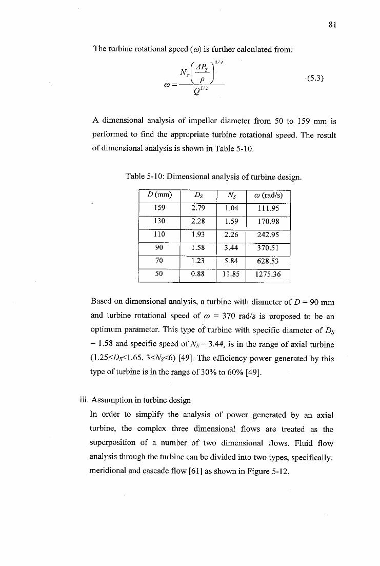
The turbine rotational speed (co) is further calculated from:
N„.
CO =
\AP
T
P J1/2
Q
3/4
(5.3)
A dimensional analysis of impeller diameter from 50 to 159 mm is
performed to find the appropriate turbine rotational speed. The result
of dimensional analysis is shown in Table 5-10.
Table 5-10: Dimensional analysis of turbine design.
D(mm) Ds Ns co(rad/s)
159 2.79 1.04 111.95
130 2.28 1.59 170.98
110 1.93 2.26 242.95
90 1.58 3.44 370.51
70 1.23 5.84 628.53
50 0.88 11.85 1275.36
Based on dimensional analysis, a turbine with diameter of D = 90 mm
and turbine rotational speed of co = 370 rad/s is proposed to be an
optimum parameter. This type of turbine with specific diameter of Ds
= 1.58 and specific speed ofNs= 3.44, is in the range of axial turbine
(1.25<Z>5<1.65, 3<Ns<6) [49]. The efficiency power generated by this
type of turbine is in the range of 30% to 60% [49].
iii. Assumption in turbine design
In order to simplify the analysis of power generated by an axial
turbine, the complex three dimensional flows are treated as the
superposition of a number of two dimensional flows. Fluid flow
analysis through the turbine can be divided into two types, specifically:
meridional and cascade flow [61] as shown in Figure 5-12.
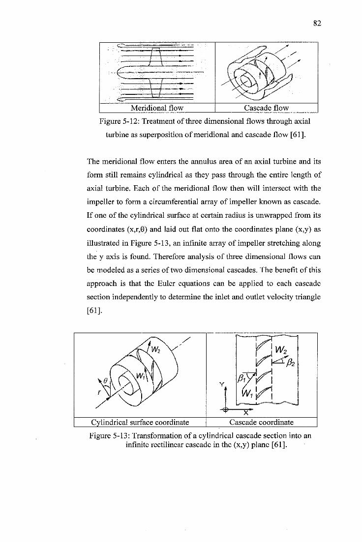
82
<c^=
•R
±d
Meridional flow Cascade flow
Figure 5-12: Treatment of three dimensional flows through axial
turbine as superposition of meridional and cascade flow [61].
The meridional flow enters the annulus area of an axial turbine and its
form still remains cylindrical as they pass through the entire length of
axial turbine. Each of the meridional flow then will intersect with the
impeller to form a circumferential array of impeller known as cascade.
If one of the cylindrical surface at certain radius is unwrapped from its
coordinates (x,r,0) and laid out flat onto the coordinates plane (x,y) as
illustrated in Figure 5-13, an infinite array of impeller stretching along
the y axis is found. Therefore analysis of three dimensional flows can
be modeled as a series of two dimensional cascades. The benefit of this
approach is that the Euler equations can be applied to each cascade
section independently to determine the inlet and outlet velocity triangle
[61].
y
f jW2
YPW*\w1* ^
-€*-x
Cylindrical surface coordinate Cascade coordinate
Figure 5-13: Transformation of a cylindrical cascade section into aninfinite rectilinear cascade in the (x,y) plane [61].
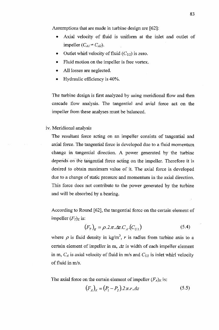
83
Assumptions that are made in turbine design are [62]:
• Axial velocity of fluid is uniform at the inlet and outlet of
impeller (CAi - CAi)-
• Outlet whirl velocity of fluid (Cut) is zero.
• Fluid motion on the impeller is free vortex.
• All losses are neglected.
• Hydraulic efficiency is 40%.
The turbine design is first analyzed by using meridional flow and then
cascade flow analysis. The tangential and axial force act on the
impeller from these analyses must be balanced.
iv. Meridional analysis
The resultant force acting on an impeller consists of tangential and
axial force. The tangential force is developed due to a fluid momentum
change in tangential direction. A power generated by the turbine
depends on the tangential force acting on the impeller. Therefore it is
desired to obtain maximum value of it. The axial force is developed
due to a change of static pressure and momentum in the axial direction.
This force does not contribute to the power generated by the turbine
and will be absorbed by a bearing.
According to Round [62], the tangential force on the certain element of
impeller (Ft)e is:
{FT)E=p.2.n.Az.CA{Cul) (5-4)
where p is fluid density in kg/m3, r is radius from turbine axis to a
certain element of impeller in m, Az is width of each impeller element
in m, Ca is axial velocity of fluid in m/s and Cm is inlet whirl velocity
of fluid in m/s.
The axial force on the certain element of impeller (Fa)e is:
{FA)E={Pi-P2)-2-n.r.Az (5.5)
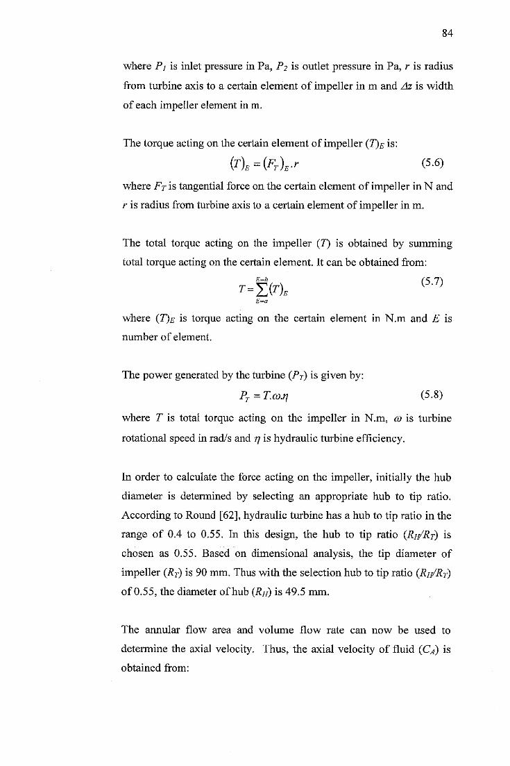
84
where Pj is inlet pressure in Pa, P2 is outlet pressure in Pa, r is radius
from turbine axis to a certain element of impeller in m and Az is width
of each impeller element in m.
The torque acting on the certain element of impeller (T)E is:
{T)E={FT)E.r (5.6)
where FT is tangential force on the certain element of impeller in N and
r is radius from turbine axis to a certain element of impeller in m.
The total torque acting on the impeller (7) is obtained by summing
total torque acting on the certain element. It can be obtained from:
T=Ef(T)E (5'7)
where (T)e is torque acting on the certain element in N.m and E is
number of element.
The power generated by the turbine (Pj) is given by:
Pf=T.co.n (5.8)
where T is total torque acting on the impeller in N.m, co is turbine
rotational speed in rad/s and rj is hydraulic turbine efficiency.
In order to calculate the force acting on the impeller, initially the hub
diameter is determined by selecting an appropriate hub to tip ratio.
According to Round [62], hydraulic turbine has a hub to tip ratio in the
range of 0.4 to 0.55. In this design, the hub to tip ratio (Rr/Rt) is
chosen as 0.55. Based on dimensional analysis, the tip diameter of
impeller (RT) is 90 mm. Thus with the selection hub to tip ratio (Rh/Rt)
of 0.55, the diameter of hub (Rh) is 49.5 mm.
The annular flow area and volume flow rate can now be used to
determine the axial velocity. Thus, the axial velocity of fluid (Ca) is
obtained from:
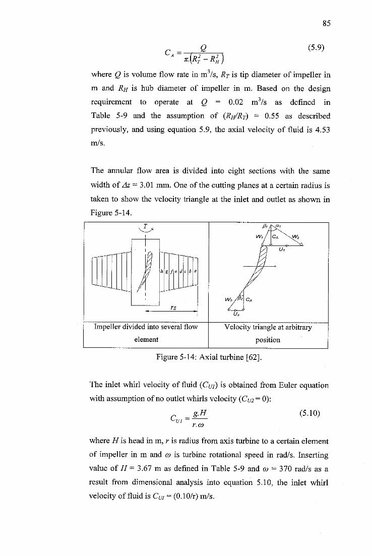
85
CA *•{*}-Rh)Q (5.9)
where Q is volume flow rate in m /s, Rp is tip diameter of impeller in
m and Rh is hub diameter of impeller in m. Based on the design
requirement to operate at Q = 0.02 m3/s as defined in
Table 5-9 and the assumption of (Rh/Rt) — 0.55 as described
previously, and using equation 5.9, the axial velocity of fluid is 4.53
m/s.
The annular flow area is divided into eight sections with the same
width of Az = 3.01 mm. One of the cutting planes at a certain radius is
taken to show the velocity triangle at the inlet and outlet as shown in
Figure 5-14.
Impeller divided into several flow
element
Velocity triangle at arbitrary
position
Figure 5-14: Axial turbine [62].
The inlet whirl velocity of fluid (Cui) is obtained from Euler equation
with assumption of no outlet whirls velocity (Cm= 0):
g.H (5.10)C =^ui
r.co
where H is head in m, r is radius from axis turbine to a certain element
of impeller in m and co is turbine rotational speed in rad/s. Inserting
value of H = 3.67 m as defined in Table 5-9 and co - 370 rad/s as a
result from dimensional analysis into equation 5.10, the inlet whirl
velocity of fluid is CU} = (0.10/r) m/s.
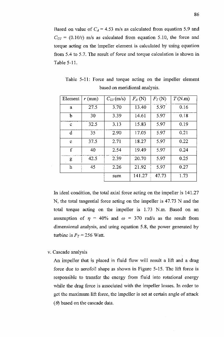
86
Based on value of Ca = 4.53 m/s as calculated from equation 5.9 and
Cui = (0.10/r) m/s as calculated from equation 5.10, the force and
torque acting on the impeller element is calculated by using equation
from 5.4 to 5.7. The result of force and torque calculation is shown in
Table 5-11.
Table 5-11: Force and torque acting on the impeller element
based on meridional analysis.
Element r (mm) Cm (m/s) FAm Fr(N) 7 (N.m)
a 27.5 3.70 13.40 5.97 0.16
b 30 3.39 14.61 5.97 0.18
c 32.5 3.13 15.83 5.97 0.19
d 35 2.90 17.05 5.97 0.21
e 37.5 2.71 18.27 5.97 0.22
f 40 2.54 19.49 5.97 0.24
g 42.5 2.39 20.70 5.97 0.25
h 45 2.26 21.92 5.97 0.27
sum 141.27 47.73 1.73
In ideal condition, the total axial force acting on the impeller is 141.27
N, the total tangential force acting on the impeller is 47.73 N and the
total torque acting on the impeller is 1.73 N.m. Based on an
assumption of r} = 40% and co = 370 rad/s as the result from
dimensional analysis, and using equation 5.8, the power generated by
turbine is PT = 256 Watt.
v. Cascade analysis
An impeller that is placed in fluid flow will result a lift and a drag
force due to aerofoil shape as shown in Figure 5-15. The lift force is
responsible to transfer the energy from fluid into rotational energy
while the drag force is associated with the impeller losses. In order to
get the maximum lift force, the impeller is set at certain angle of attack
(6) based on the cascade data.
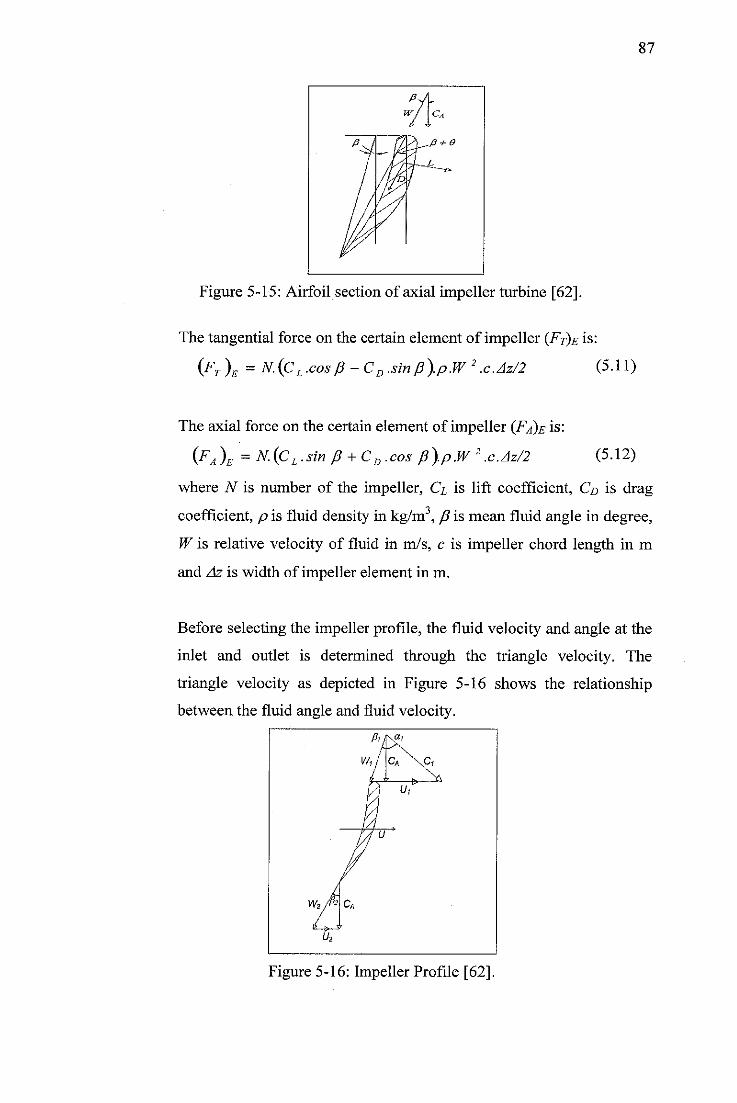
87
Figure 5-15: Airfoil section of axial impeller turbine [62].
The tangential force on the certain element of impeller (Ft)e is:
(FT )e = N.(CL .cosp - CD .sinp).p.W 2.c.Az/2 (5.11)
The axial force on the certain element of impeller (Fa)e is:
(FA)e = N.(CL.sin p + CD.cos p).p.W 2.c.Az/2 (5.12)
where N is number of the impeller, Cl is lift coefficient, Cd is drag
coefficient, p is fluid density in kg/m3, p is mean fluid angle in degree,
W is relative velocity of fluid in m/s, c is impeller chord length in m
and Az is width of impeller element in m.
Before selecting the impeller profile, the fluid velocity and angle at the
inlet and outlet is determined through the triangle velocity. The
triangle velocity as depicted in Figure 5-16 shows the relationship
between the fluid angle and fluid velocity.
Figure 5-16: Impeller Profile [62].
88
The impeller speed at certain radius (CO is given by,
U = co.r (5.13)
where co is turbine rotational speed in rad/s and r is radius from axis
turbine to a certain element of impeller in m.
Based on the known value of axial velocity of fluid (Ca) and the inlet
whirl velocity of fluid (Cm) from the meridional analysis, the inlet
fluid angle (pi) is calculated from:
(5.14)u *- u iPj = tan -i
The relative velocity of fluid at the inlet (Wj) is obtained from the
geometric relation:
Similarly, the fluid angle at the outlet is determined by referring to the
Figure 5-16. Thus the outlet fluid angle (fij) is given by:
r rr \ (5.16)p 2 = tan -i U
c
The relative velocity at the outlet (Wj) is obtained from the geometric
relation:
(5.17)w2 = jc2A +(uy
The mean fluid angle (fiu) is determined from:
Pi +02Pm =
2
(5.18)
The mean relative velocity of fluid (W) is obtained from:
Wj+W2 (5.19)W =
2
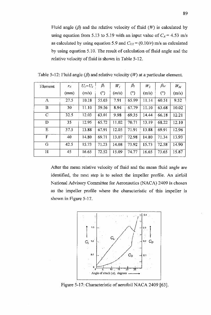
89
Fluid angle (p) and the relative velocity of fluid (W) is calculated by
using equation from 5.13 to 5.19 with an input value of Ca = 4.53 m/s
as calculated by using equation 5.9 and Cui = (0.10/r) m/s as calculated
by using equation 5.10. The result of calculation of fluid angle and the
relative velocity of fluid is shown in Table 5-12.
Table 5-12: Fluid angle (p) and relative velocity (W) at a particular element.
Element rE
(mm) (m/s) (°)
Wi
(m/s)
fa
(°)
w2
(m/s)
Pu
O
wM
(m/s)
A 27.5 10.18 55.03 7.91 65.99 11.14 60.51 9.52
B 30 11.10 59.56 8.94 67.79 11.10 63.68 10.02
C 32.5 12.03 63.01 9.98 69.35 14.44 66.18 12.21
D 35 12.95 65.72 11.02 70.71 13.19 68.22 12.10
E 37.5 13.88 67.91 12.05 71.91 13.88 69.91 12.96
F 40 14.80 69.71 13.07 72.98 14.80 71.34 13.93
G 42.5 15.73 71.23 14.08 73.92 15.73 72.58 14.90
H 45 16.65 72.52 15.09 74.77 16.65 73.65 15.87
After the mean relative velocity of fluid and the mean fluid angle are
identified, the next step is to select the impeller profile. An airfoil
National Advisory Committee for Aeronautics (NACA) 2409 is chosen
as the impeller profile where the characteristic of this impeller is
shown in Figure 5-17.
Figure 5-17: Characteristic of aerofoil NACA 2409 [63].
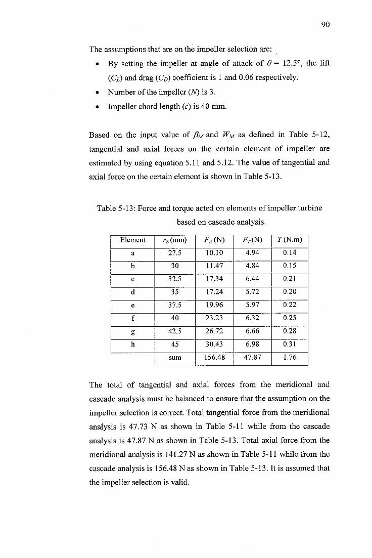
90
The assumptions that are on the impeller selection are:
• By setting the impeller at angle of attack of 6 - 12.5°, the lift
(Cl) and drag (Co) coefficient is 1 and 0.06 respectively.
• Number of the impeller (TV) is 3.
• Impeller chord length (c) is 40 mm.
Based on the input value of pu and Wm as defined in Table 5-12,
tangential and axial forces on the certain element of impeller are
estimated by using equation 5.11 and 5.12. The value of tangential and
axial force on the certain element is shown in Table 5-13.
Table 5-13: Force and torque acted on elements of impeller turbine
based on cascade analysis.
Element rE(mm) FA(N) FT(N) T(N.m)
a 27.5 10.10 4.94 0.14
b 30 11.47 4.84 0.15
c 32.5 17.34 6.44 0.21
d 35 17.24 5.72 0.20
e 37.5 19.96 5.97 0.22
f 40 23.23 6.32 0.25
g 42.5 26.72 6.66 0.28
h 45 30.43 6.98 0.31
sum 156.48 47.87 1.76
The total of tangential and axial forces from the meridional and
cascade analysis must be balanced to ensure that the assumption on the
impeller selection is correct. Total tangential force from the meridional
analysis is 47.73 N as shown in Table 5-11 while from the cascade
analysis is 47.87 N as shown in Table 5-13. Total axial force from the
meridional analysis is 141.27 N as shown in Table 5-11 while from the
cascade analysis is 156.48 N as shown in Table 5-13. It is assumed that
the impeller selection is valid.
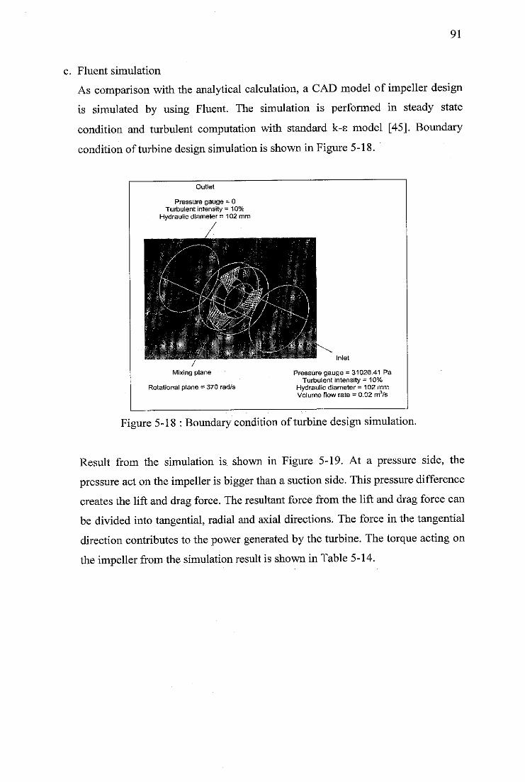
91
c. Fluent simulation
As comparison with the analytical calculation, a CAD model of impeller design
is simulated by using Fluent. The simulation is performed in steady state
condition and turbulent computation with standard k-s model [45]. Boundary
condition of turbine design simulation is shown in Figure 5-18.
Outlet
Pressure gauge = 0Turbulent Intensity = 10%
Hydraulic diameter = 102 mm
Mixing plane
Rotational plane = 370 rad/s
Kf?»r- Inlet
Pressure gauge = 31026.41 PaTurbulent intensity = 10%
Hydraulic diameter = 102 mmVolume llow rate = 0.02 m3/s
Figure 5-18 : Boundary condition of turbinedesignsimulation.
Result from the simulation is shown in Figure 5-19. At a pressure side, the
pressure actonthe impeller is bigger than a suction side. This pressure difference
creates the lift and drag force. The resultant force from the lift and drag force can
be divided into tangential, radial and axial directions. The force in the tangential
direction contributes to the power generated by the turbine. The torque acting on
the impeller fromthe simulation result is shown in Table 5-14.
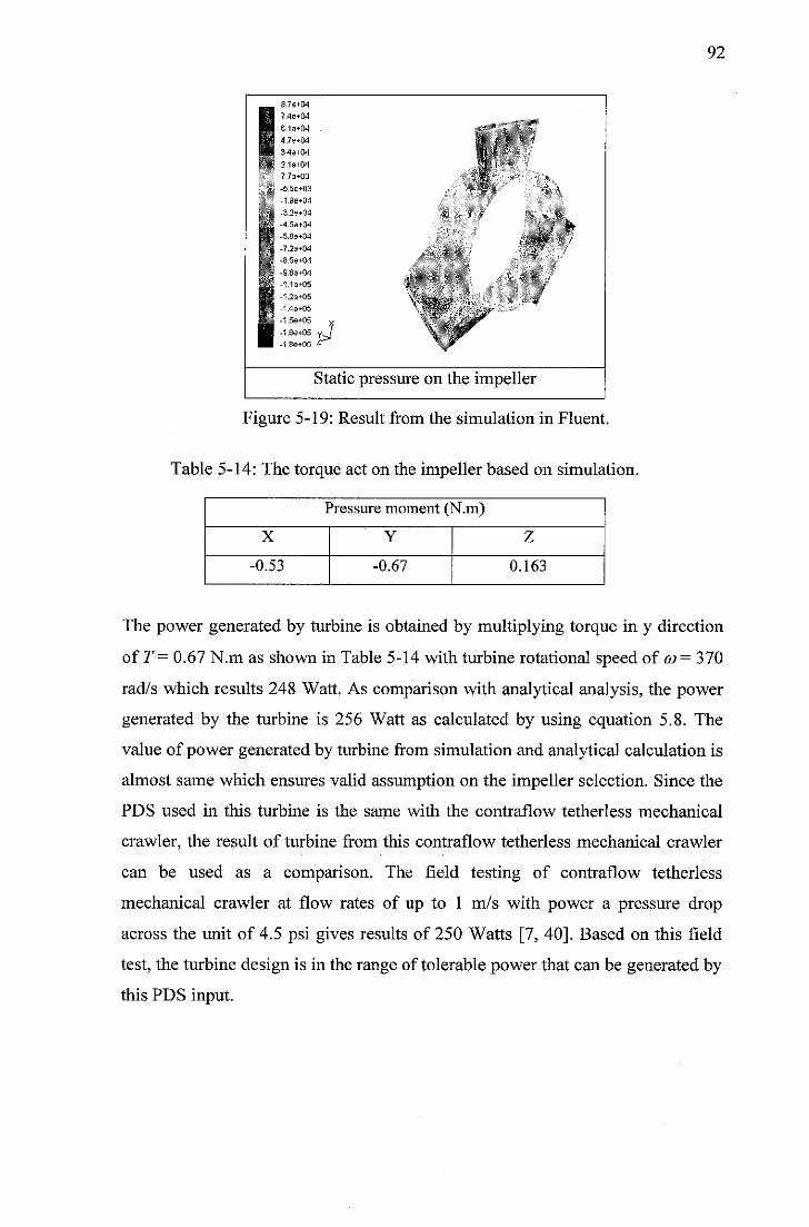
8.7e+04
H 7'4e+04H e-1e+°4H 4.7e+04 *
H 3.4e+04 1»S«| 2.1e-i-04
7.7e+03J
-5 5e+03
-1 9e+04
-3 2e+04
jg|| -4 5s+04V1'ffl -58e+04
jl -7 2e+04Ml -8 5e+04jKJ -9 89+04111 1le+05 \ ,
S ' 2e"*"GS•H 14e+05HH -1 5e+05Bfi -1.6e+05 J
\.^
*
J-
II -1.88+05 z-* y
Static pressure on the impell sr
Figure 5-19: Result from the simulation in Fluent.
Table 5-14: The torque act on the impeller based on simulation.
Pressure moment (N.m)
X Y Z
-0.53 -0.67 0.163
92
The power generated by turbine is obtained by multiplying torque in y direction
of T = 0.67 N.m as shown in Table 5-14 with turbine rotational speed of co = 370
rad/s which results 248 Watt. As comparison with analytical analysis, the power
generated by the turbine is 256 Watt as calculated by using equation 5.8. The
value of power generated by turbine from simulation and analytical calculation is
almost same which ensures valid assumption on the impeller selection. Since the
PDS used in this turbine is the same with the contrafiow tetherless mechanical
crawler, the result of turbine from this contraflow tetherless mechanical crawler
can be used as a comparison. The field testing of contraflow tetherless
mechanical crawler at flow rates of up to 1 m/s with power a pressure drop
across the unit of 4.5 psi gives results of 250 Watts [7, 40]. Based on this field
test, the turbine design is in the range of tolerable power that can be generated by
this PDS input.
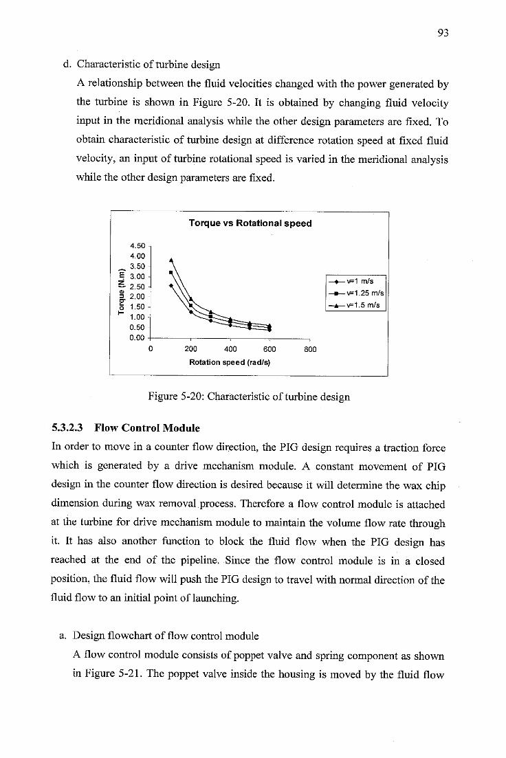
93
d. Characteristic of turbine design
A relationship between the fluid velocities changed with the power generated by
the turbine is shown in Figure 5-20. It is obtained by changing fluid velocity
input in the meridional analysis while the other design parameters are fixed. To
obtain characteristic of turbine design at difference rotation speed at fixed fluid
velocity, an input of turbine rotational speed is varied in the meridional analysis
while the other design parameters are fixed.
Torque vs Rotational speed
4.50 -
4.00 -
~ 3.50 -E 3.00 -
~ 2.50 -
= 2.00 -
\
V—♦—v=1 m/s
-•—v=1.25m/s
o 1.50 -
*~ 1.00 -I ^fe^ —a—v=1.5 m/s
0.50 ^^feater*
(] 200 400 600 800
Rotation speed (rad/s)
Figure 5-20: Characteristic of turbine design
5.3.2.3 Flow Control Module
In order to move in a counter flow direction, the PIG design requires a traction force
which is generated by a drive mechanism module. A constant movement of PIG
design in the counter flow direction is desired because it will determine the wax chip
dimension during wax removal process. Therefore a flow control module is attached
at the turbine for drive mechanism module to maintain the volume flow rate through
it. It has also another function to block the fluid flow when the PIG design has
reached at the end of the pipeline. Since the flow control module is in a closed
position, the fluid flow will push the PIG design to travel with normal direction of the
fluid flow to an initial point of launching.
a. Design flowchart of flow control module
A flow control module consists of poppet valve and spring component as shown
in Figure 5-21. The poppet valve inside the housing is moved by the fluid flow
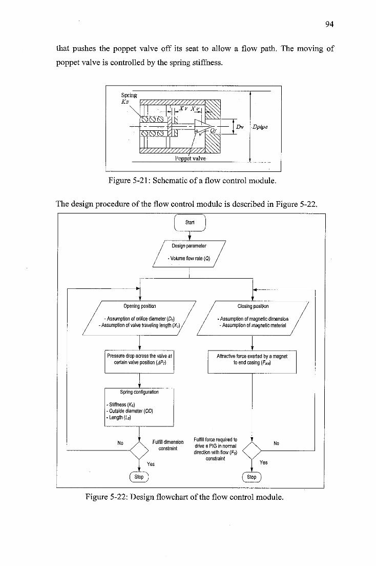
94
that pushes the poppet valve off its seat to allow a flow path. The moving of
poppet valve is controlled by the spring stiffness.
SpringKs V///////////777777\
IMS
yXvXv^
<S3tS3«S ty
V///////////771
Poppet valve
Dpipe
Figure 5-21: Schematic of a flow control module.
The design procedure of the flow control module is described in Figure 5-22.
Start
1 '
I Design parameter /
/ -Volume flow rale (Q) /
1
/ "A
'
Opening position
Assumption oforifice diameter (Dvssumption of valvetraveling length
// / Closing position
/ -Assumption of magnetic dimension/ -Assumption of magnetic materia! /
i •
Pressure drop across the valve atcertainvalveposition (APT)
Attractive force exerted bya magnetto end casing (Fm)
' j
Spring configuration
- Stiffness (Ks)- Outsidediameter(OD)• Length (Ls)
\ No1
No / \ Fulfill dime\ constra
nsion ^u^" ^orce recly'rec't0lt drive aPIG in normal /
(st
Yes
directs n with flow (Fs) \onstraint \
( St
Yes
Figure 5-22: Design flowchart of the flow control module.
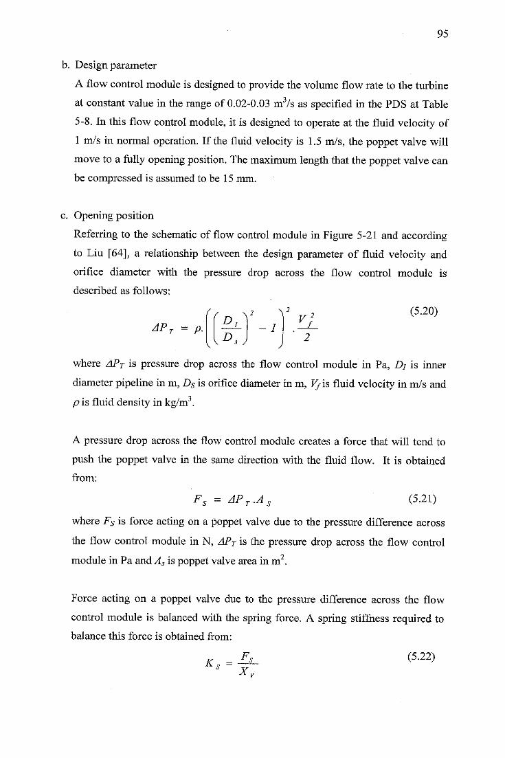
95
b. Design parameter
A flow control module is designed to provide the volume flow rate to the turbine
at constant value in the range of 0.02-0.03 m3/s as specified in the PDS at Table
5-8. In this flow control module, it is designed to operate at the fluid velocity of
1 m/s in normal operation. If the fluid velocity is 1.5 m/s, the poppet valve will
move to a fully opening position. The maximum length that the poppet valve can
be compressed is assumed to be 15 mm.
c. Opening position
Referring to the schematic of flow control module in Figure 5-21 and according
to Liu [64], a relationship between the design parameter of fluid velocity and
orifice diameter with the pressure drop across the flow control module is
described as follows:
((r, V V y* (5'2°)APT = p. - I f
2
where APT is pressure drop across the flow control module in Pa, £>/ is inner
diameter pipeline in m, Ds is orifice diameter in m, V/\s fluid velocity in m/s and
p is fluid density in kg/m3.
A pressure drop across the flow control module creates a force that will tend to
push the poppet valve in the same direction with the fluid flow. It is obtained
from:
Fs = APT.AS (5.21)
where Fs is force acting on a poppet valve due to the pressure difference across
the flow control module in N, APT is the pressure drop across the flow control
module in Pa andAs is poppet valve areain m2.
Force acting on a poppet valve due to the pressure difference across the flow
control module is balanced with the spring force. A spring stiffness required to
balance this force is obtained from:
Fs (5.22)Ks =
Xy
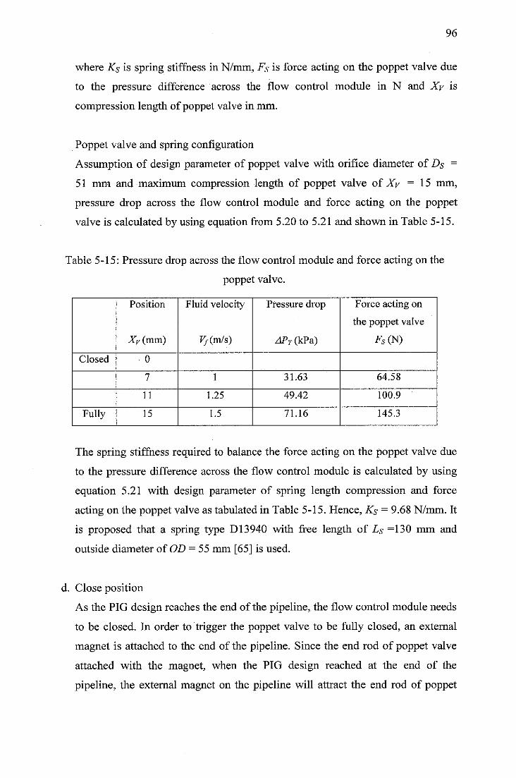
96
where Ks is spring stiffness in N/mm, Fs is force acting on the poppet valve due
to the pressure difference across the flow control module in N and Xy is
compression length of poppet valve in mm.
Poppet valve and spring configuration
Assumption of design parameter of poppet valve with orifice diameter of Ds =
51 mm and maximum compression length of poppet valve of Xy = 15 mm,
pressure drop across the flow control module and force acting on the poppet
valve is calculated by using equation from 5.20 to 5.21 and shown in Table 5-15.
Table 5-15: Pressure drop across the flow control module and force acting on the
poppet valve.
Position
Xv (mm)
Fluid velocity
F/(m/s)
Pressure drop
zl/V(kPa)
Force acting on
the poppet valve
FS(N)
Closed 0
7 1 31.63 64.58
11 1.25 49.42 100.9
Fully 15 1.5 71.16 145.3
The spring stiffness required to balance the force acting on the poppet valve due
to the pressure difference across the flow control module is calculated by using
equation 5.21 with design parameter of spring length compression and force
acting on the poppet valve as tabulated in Table 5-15. Hence, Ks = 9.68 N/mm. It
is proposed that a spring type D13940 with free length of Ls =130 mm and
outside diameter of OD = 55 mm [65] is used.
d. Close position
As the PIG design reaches the end of the pipeline, the flow control module needs
to be closed. In order to trigger the poppet valve to be fully closed, an external
magnet is attached to the end of the pipeline. Since the end rod of poppet valve
attached with the magnet, when the PIG design reached at the end of the
pipeline, the external magnet on the pipeline will attract the end rod of poppet
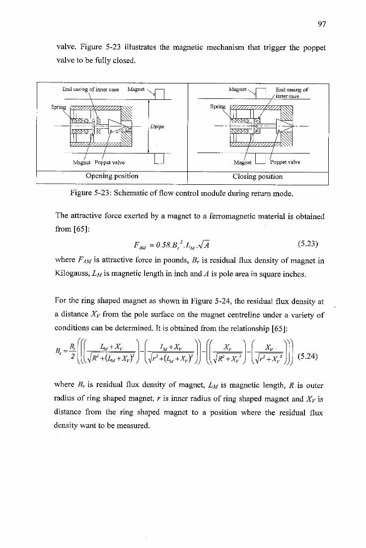
97
valve. Figure 5-23 illustrates the magnetic mechanism that trigger the poppet
valve to be fully closed.
End casing of inner case Magnet
Spring
Magnet Poppet valve
Opening position
Magnet
Magnet
End casing of/inner case
Poppet valve
Closing position
Figure 5-23: Schematic of flow control module during return mode.
The attractive force exerted by a magnet to a ferromagnetic material is obtained
from [65]:
FAU=0.58.Br2.LM.J2'M-(5.23)
where FAM is attractive force in pounds, Br is residual flux density of magnet in
Kilogauss, Lm is magnetic length in inch and A is pole area in square inches.
For the ring shaped magnet as shown in Figure 5-24, the residual flux density at
a distance Xy from the pole surface on the magnet centreline under a variety of
conditions can be determined. It is obtained from the relationship [65]:
x 2
(ffI^+Xv
v\\je+^+Xyf
LM+XyY\
r'+i^+Xy)2JJ
(fX„ x„
Ky,R2+Xy j aP+^
\W
2
v JJ)(5.24)
where Br is residual flux density of magnet, LM is magnetic length, R is outer
radius of ring shaped magnet, r is inner radius of ring shaped magnet and Xy is
distance from the ring shaped magnet to a position where the residual flux
density want to be measured.
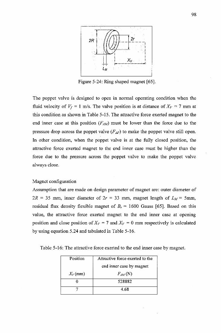
2R
,r
7/1H 2r
w.„ „
! xv
L w
98
Figure 5-24: Ring shaped magnet [65].
The poppet valve Is designed to open in normal operating condition when the
fluid velocity of V/ —1 m/s. The valve position is at distance of Xy = 7 mm at
this condition as shown in Table 5-15. The attractive force exerted magnet to the
end inner case at this position (Fam) must be lower than the force due to the
pressure drop across the poppet valve (F^p) to make the poppet valve still open.
In other condition, when the poppet valve is at the fully closed position, the
attractive force exerted magnet to the end inner case must be higher than the
force due to the pressure across the poppet valve to make the poppet valve
always close.
Magnet configuration
Assumption that are made on design parameter of magnet are: outer diameter of
2R = 35 mm, inner diameter of 2r = 33 mm, magnet length of Lm = 5mm,
residual flux density flexible magnet of Br ~ 1600 Gauss [65]. Based on this
value, the attractive force exerted magnet to the end inner case at opening
position and close position ofXy = 1 and Xy = 0 mm respectively is calculated
by using equation 5.24 and tabulated in Table 5-16.
Table 5-16: The attractive force exerted to the end inner case by magnet.
Position
Xy (mm)
Attractive force exerted to the
end inner case by magnet
Fam(N
0 528882
7 4.68
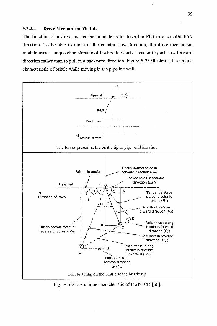
99
5.3.2.4 Drive Mechanism Module
The function of a drive mechanism module is to drive the PIG in a counter flow
direction. To be able to move in the counter flow direction, the drive mechanism
module uses a unique characteristic of the bristle which is easier to push in a forward
direction rather than to pull in a backward direction. Figure 5-25 illustrates the unique
characteristic of bristle while moving in the pipeline wall.
Rn
Pipe wall p. Rw
Bristle,
Brush core
<tDirection of travel
The forces present at the bristle tip to pipe wall interface
Bristle tip angle
Pipe wall
Direction of travel
Bristle normal force in
reverse direction (R'w)
Bristle normal force in
forward direction (RN)
Friction force in forward
direction <j£.Rn)
Tangential forceperpendicular to
bristle (RT)
Resultant force in
forward direction (RR)
Axial thrust alongbristle in forward
direction (RA)
Resultant in reverse
direction (R'R)
Axial thrust alongbristle in reverse
direction (R'A)Friction force in
reverse direction
(lx.R'N)
Forces acting on the bristle at the bristle tip
Figure 5-25: A unique characteristic of the bristle [66].
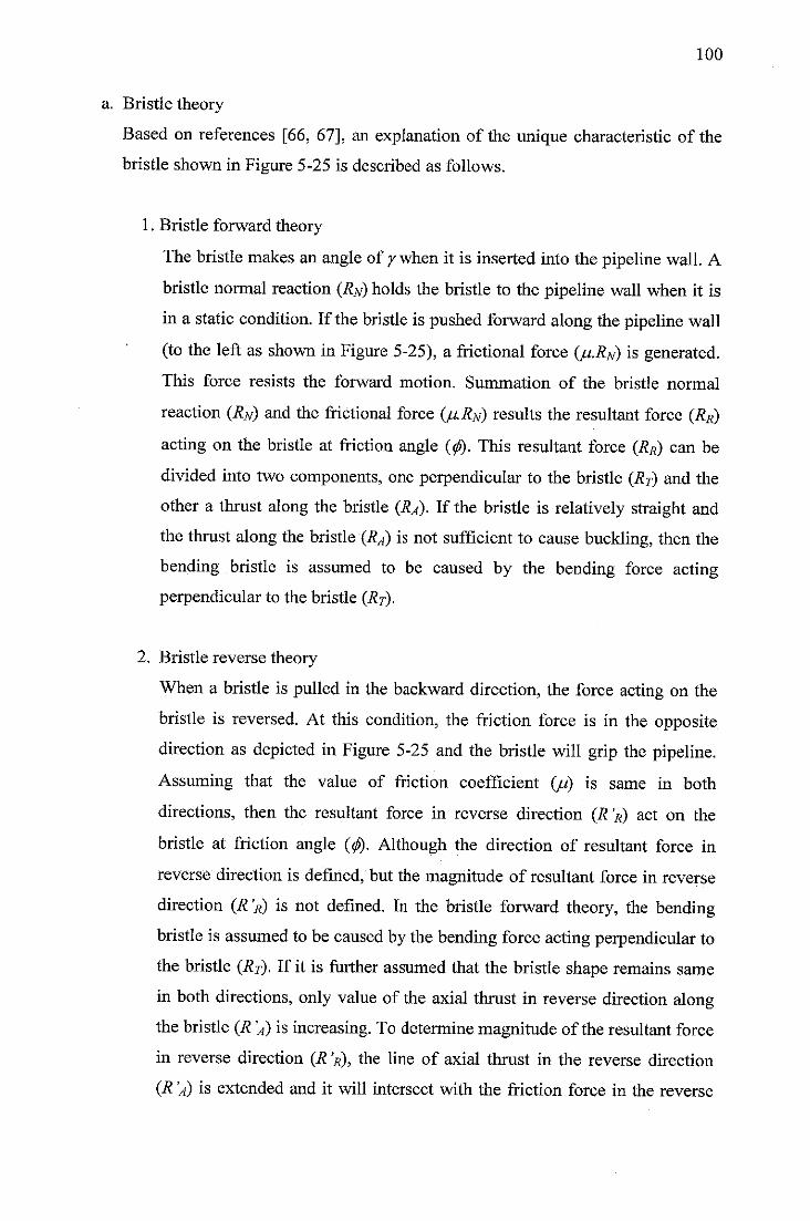
100
a. Bristle theory
Based on references [66, 67], an explanation of the unique characteristic of the
bristle shown in Figure 5-25 is described as follows.
1. Bristle forward theory
The bristle makes an angle of ywhen it is inserted into the pipeline wall. A
bristle normal reaction (RN) holds the bristle to the pipeline wall when it is
in a static condition. If the bristle is pushed forward along the pipeline wall
(to the left as shown in Figure 5-25), a frictional force (p.RN) is generated.
This force resists the forward motion. Summation of the bristle normal
reaction (RN) and the frictional force (p.RN) results the resultant force (RR)
acting on the bristle at friction angle ((f). This resultant force (RR) can be
divided into two components, one perpendicular to the bristle (RT) and the
other a thrust along the bristle (RA). If the bristle is relatively straight and
the thrust along the bristle (RA) is not sufficient to cause buckling, then the
bending bristle is assumed to be caused by the bending force acting
perpendicular to the bristle (Rj).
2. Bristle reverse theory
When a bristle is pulled in the backward direction, the force acting on the
bristle is reversed. At this condition, the friction force is in the opposite
direction as depicted in Figure 5-25 and the bristle will grip the pipeline.
Assuming that the value of friction coefficient (/J) is same in both
directions, then the resultant force in reverse direction (R'R) act on the
bristle at friction angle ($. Although the direction of resultant force in
reverse direction is defined, but the magnitude of resultant force in reverse
direction (R'R) is not defined. In the bristle forward theory, the bending
bristle is assumedto be causedby the bending force acting perpendicular to
the bristle (RT). If it is further assumed that the bristle shape remains same
in both directions, only value of the axial thrust in reverse direction along
the bristle (R 'A) is increasing. To determine magnitude of the resultant force
in reverse direction (R 'R), the line of axial thrust in the reverse direction
(R 'A) is extended and it will intersect with the friction force in the reverse
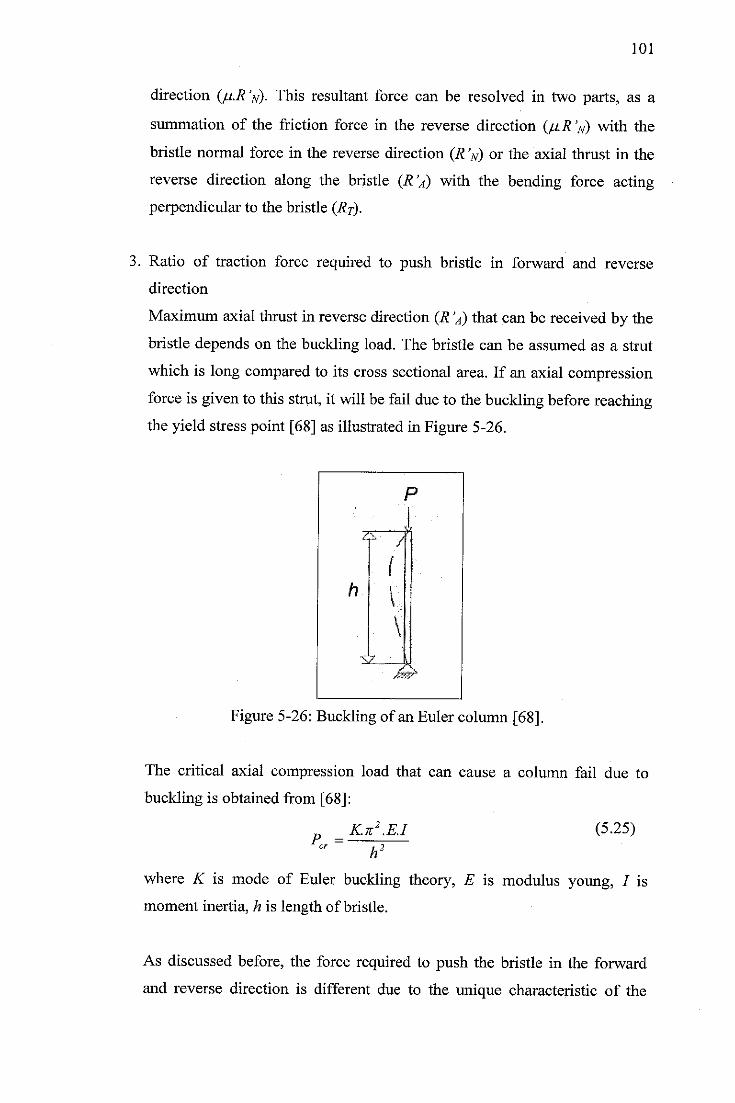
101
direction (/j.R'n). This resultant force can be resolved in two parts, as a
summation of the friction force in the reverse direction (/iR V) with the
bristle normal force in the reverse direction (RV) or the axial thrust in the
reverse direction along the bristle (R'A) with the bending force acting
perpendicular to the bristle (Rr).
3. Ratio of traction force required to push bristle in forward and reverse
direction
Maximum axial thrust in reverse direction (R 'A) that can be received by the
bristle depends on the buckling load. The bristle can be assumed as a strut
which is long compared to its cross sectional area. If an axial compression
force is givento this strut, it will be fail due to the buckling before reaching
the yield stress point [68] as illustrated in Figure 5-26.
Figure 5-26: Buckling of an Euler column [68].
The critical axial compression load that can cause a column fail due to
buckling is obtained from [68]:
K.k2.EJ (5.25)P... =
h
where K is mode of Euler buckling theory, E is modulus young, / is
moment inertia, h is length of bristle.
As discussed before, the force required to push the bristle in the forward
and reverse direction is different due to the unique characteristic of the
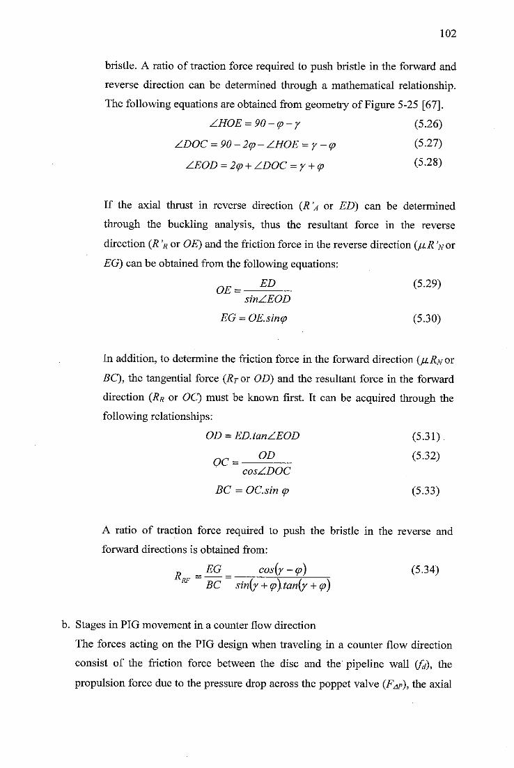
102
bristle. A ratio of traction force required to push bristle in the forward and
reverse direction can be determined through a mathematical relationship.
The following equations are obtained from geometry of Figure 5-25 [67].
ZHOE = 90-cp-y (5.26)
ZDOC = 90-2cp- ZHOE = y-<p (5.27)
ZEOD =2<p +ZDOC =y + <p (5-28)
If the axial thrust in reverse direction (R 'a or ED) can be determined
through the buckling analysis, thus the resultant force in the reverse
direction (R 'R or OE) and the friction force in the reverse direction (p.R Vor
EG) can be obtained from the following equations:
OE= ED (5-29)sinZEOD
EG = OE.sincp (5.30)
In addition, to determine the friction force in the forward direction (p.RNor
BC), the tangential force (RT or OD) and the resultant force in the forward
direction (RR or OC) must be known first. It can be acquired through the
following relationships:
OD = ED.tanZEOD (5.31)
oc= OD (5-32)cosZDOC
BC = OC.sin cp (5.33)
A ratio of traction force required to push the bristle in the reverse and
forward directions is obtained from:
R „EG _ cos(y-<p) (5.34)*~RF BC sin(y +cp). tan(y +cp)
b. Stages in PIG movement in a counter flow direction
The forces acting on the PIG design when traveling in a counter flow direction
consist of the friction force between the disc and the pipeline wall (Q, the
propulsion force due to the pressure drop across the poppet valve (Fap), the axial
103
force generated by the turbine (Fa) and the friction force between the bristle and
the pipeline wall (fm), A free body diagram that shows the force acting on the
PIG when moving in the counter flow direction is illustrated in Figure 5-27.
Fixed Fixed
bristle bristle qjsc
Vflaw VpIG
Poppet valvelmPeller Cutter
\fi.ND Tfi.No
loving bristle Nd Nd
JZZZZZZZZZZ2ZZZ1
V////S3R2ZZZ
'ssss/s/s/y/Ty,
Jfj.No Jju.NDND Nd
fl_EL
f^T
Figure 5-27: The forces acted on the PIG design.
The relationship between parameter of the PIG operating condition in a PDS
document with assumption of design parameter on the drive mechanism is
described as follows.
The frictional force between the PIG disc and the pipeline wall is obtained from:
L=b.Msj-Nd (5.35)
where b is number of disc, psi is sliding friction between the disc and pipeline,
and Nd denotes the normal reaction force on the PIG disc.
To determine the normal reaction force on the disc, it can be acquired from [69]:
B-AP(5.36)
Nd =2-f*s
where Dj is inner diameter pipeline, ur is the disc oversize and AP is pressure
difference across each disc which is equal to total pressure difference across the
poppet valve (APj) divided by number of disc (b).
The propulsion force due to the pressure drop across the poppet valve (Fap) is:
FAp=APT.Ad (5.37)
where APt is pressure drop between the PIG bodies and Aj is disc area.
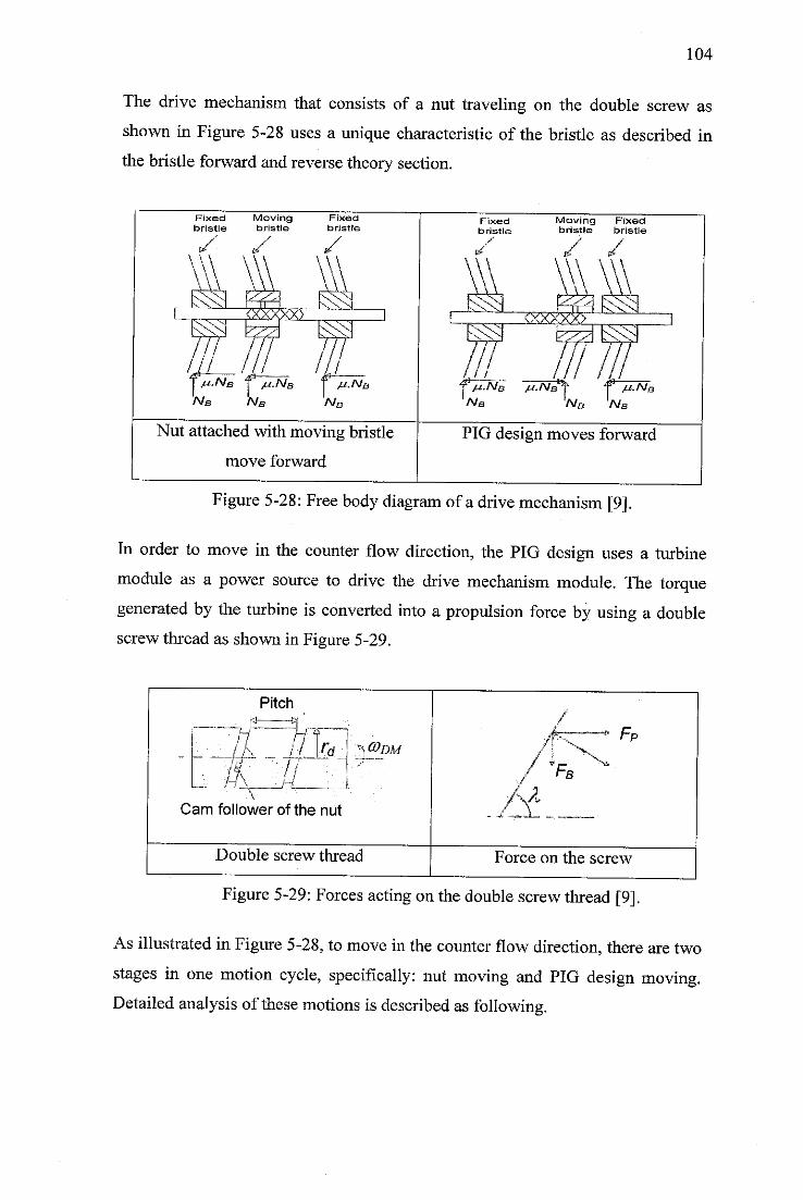
104
The drive mechanism that consists of a nut traveling on the double screw as
shown in Figure 5-28 uses a unique characteristic of the bristle as described in
the bristle forward and reverse theory section.
Nut attached with moving bristle
move forward
1nb 'a/, '•'a/£
PIG design moves forward
Figure 5-28: Free bodydiagram of a drive mechanism [9].
In order to move in the counter flow direction, the PIG design uses a turbine
module as a power source to drive the drive mechanism module. The torque
generated by the turbine is converted into a propulsion force by using a double
screw thread as shown in Figure 5-29.
Pitch
- __, |±r-ir
I i'r-f
H_rt _
Cam follower of the nut
X)®DM
Double screw thread
TB
Force on the screw
Figure 5-29: Forces acting on thedouble screw thread [9].
As illustrated in Figure 5-28, to move in the counter flowdirection, there are two
stages in one motion cycle, specifically: nut moving and PIG design moving.
Detailed analysis of these motions is described as following.
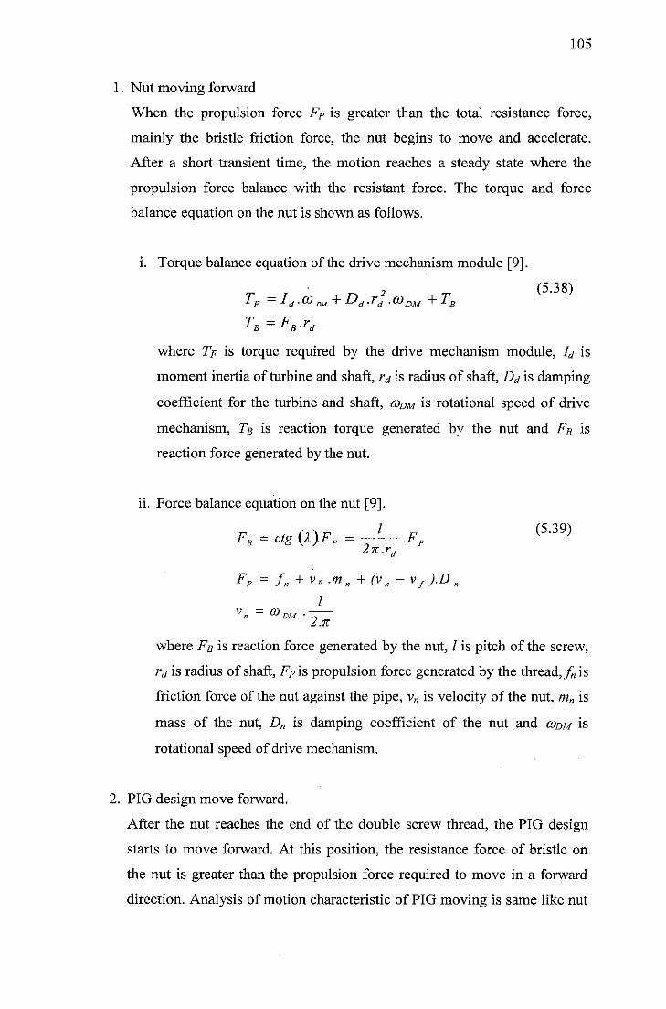
105
1. Nut moving forward
When the propulsion force FP is greater than the total resistance force,
mainly the bristle friction force, the nut begins to move and accelerate.
After a short transient time, the motion reaches a steady state where the
propulsion force balance with the resistant force. The torque and force
balance equation on the nut is shown as follows.
i. Torque balance equation of the drive mechanism module [9].
TF =Id.(Om + Dd.rd.wDU +TB
TB=FB.rd
where 7> is torque required by the drive mechanism module, Id is
moment inertia of turbine and shaft, rd is radius of shaft, Dd is damping
coefficient for the turbine and shaft, codm is rotational speed of drive
mechanism, Tb is reaction torque generated by the nut and Fb is
reaction force generated by the nut.
ii. Force balance equation on the nut [9].
Fa=ctg(X).FF=-J—.FF (539)2n.rd
Fp = fn + v„.m„ +(vn -vf).Dnf
IDM •
v_ = CO
2.K
where Fb is reaction force generated by the nut, / is pitch of the screw,
rd is radius of shaft, FP is propulsion force generated by the thread,^ is
friction force of the nut against the pipe, v„ is velocity of the nut, mn is
mass of the nut, Dn is damping coefficient of the nut and codm is
rotational speed of drive mechanism.
2. PIG design move forward.
After the nut reaches the end of the double screw thread, the PIG design
starts to move forward. At this position, the resistance force of bristle on
the nut is greater than the propulsion force required to move in a forward
direction. Analysis of motion characteristic of PIG moving is same like nut
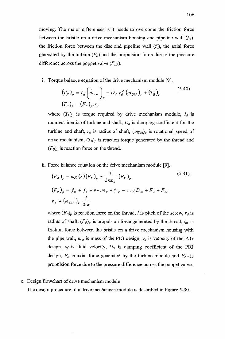
106
moving. The major differences is it needs to overcome the friction force
between the bristle on a drive mechanism housing and pipeline wall (fm),
the friction force between the disc and pipeline wall (fd), the axial force
generated by the turbine (Fa) and the propulsion force due to the pressure
difference across the poppet valve (F^p).
i. Torque balance equation of the drive mechanism module [9].
(TF )p=Id\<t>™\ +Dd *rl (<»'DM )P +(TB )PV J p
(Tb)p =iFB)p-rdwhere (Tp)p is torque required by drive mechanism module, Id is
moment inertia of turbine and shaft, Dd is damping coefficient for the
turbine and shaft, rd is radius of shaft, (g>dm)p is rotational speed of
drive mechanism, (Tb)p is reaction torque generated by the thread and
(Fb)p is reaction force on the thread.
ii. Force balance equation on the drive mechanism module [9].
(Fs)=ctg(x).(FP)=-^.(FFl (5-41)p 2wk.
0v)P = fm + fd+vp -mP+(vP-vf).Dm +FA+F.
where (Fb)p is reaction force on the thread, / is pitch of the screw, rd is
radius of shaft, (FR)p is propulsion force generated by the thread,^ is
friction force between the bristle on a drive mechanism housing with
the pipe wall, mm is mass of the PIG design, vp is velocity of the PIG
design, v/ is fluid velocity, Dm is damping coefficient of the PIG
design, Fa is axial force generated by the turbine module and F^p is
propulsion force due to the pressure difference across the poppet valve.
c. Design flowchart of drive mechanism module
The design procedure of a drive mechanism module is described in Figure 5-30.
AP
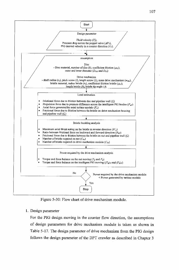
Start
Design parameter
Fluid velocity (Vj),Pressure drop across the poppet valve (APT),
PIG desired velocity in a counter direction (VP).
Assumption
Disc
- Disc material, number of disc (6), coefficient friction (jjsi),outer and inner diameter (DOD and D,D)
Drive mechanism
shaft radius (rd), pitch screw (I), length screw (L), mass drive mechanism (mrfn,),bristle material, radius bristle (rb), coefficient friction bristle (/42),
lengthbristle(h),bristle tip angle (y).
Load estimation
Frictional force due to friction between disc and pipeline wall <fd)Propulsion force due to pressure difference across the intelligent PIG bodies (F^p)Axial force generated by axial turbine module (FA)Frictional force due to friction between the bristle on drive mechanism housingand pipeline wall (fm)
Bristle buckling analysis
Maximum axial thrust acting on the bristle in reverse direction (R'A)Ratio between frictional force on backward and forward direction (Rrf)Frictional force due to friction between the bristle on nut and pipeline wall (f„)Number ofbristle required on nut (Cbn)Number ofbristle required on drive mechanism module (Cm)
I
Power required by the drive mechanism analysis
Torque and force balance on the nut moving (7a and FB)Torque and force balance on the intelligent PIG moving ((TB)p and (FB)p)
NoPower required by the drive mechanism module
< Power generated by turbine module
Yes
Stop
Figure 5-30: Flow chart of drive mechanism module.
107
1. Design parameter
For the PIG design moving in the counter flow direction, the assumptions
of design parameters for drive mechanism module is taken as shown in
Table 5-17. The design parameter of drive mechanism from the PIG design
follows the design parameter of the DPT crawler as described in Chapter 3
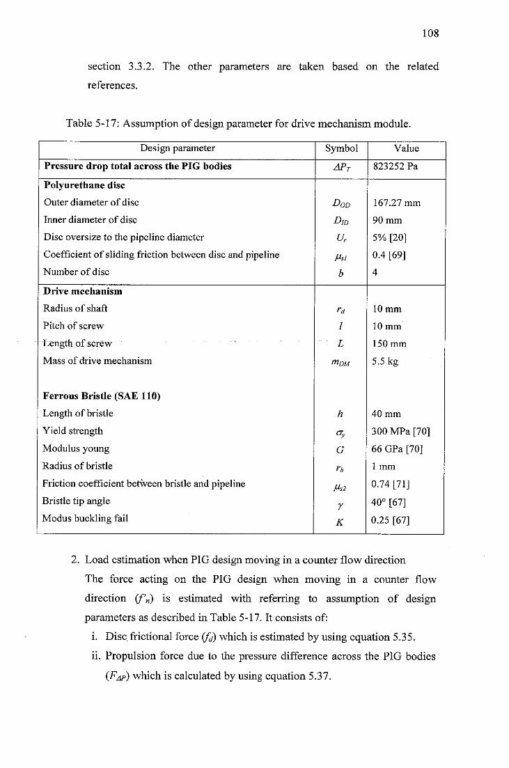
108
section 3.3.2. The other parameters are taken based on the related
references.
Table 5-17: Assumption of design parameter for drive mechanism module.
Design parameter Symbol Value
Pressure drop total across the PIG bodies APT 823252 Pa
Polyurethane disc
Outer diameter of disc
Inner diameter of disc
Disc oversize to the pipeline diameter
Coefficient of sliding friction between disc and pipeline
Number of disc
Dqd
D]D
ur
Ms!
b
167.27 mm
90 mm
5% [20]
0.4 [69]
4
Drive mechanism
Radius of shaft
Pitch of screw
Length of screw
Mass of drive mechanism
Ferrous Bristle (SAE 110)
Length of bristle
Yield strength
Modulus young
Radius of bristle
Friction coefficient between bristle and pipeline
Bristle tip angle
Modus buckling fail
rd
I
L
mDM
h
CTy
G
n
Ms2
7
K
10 mm
10 mm
150 mm
5.5 kg
40 mm
300 MPa [70]
66 GPa [70]
1 mm
0.74 [71]
40° [67]
0.25 [67]
2. Load estimation when PIG design moving in a counter flow direction
The force acting on the PIG design when moving in a counter flow
direction (f'n) is estimated with referring to assumption of design
parameters as described in Table 5-17. It consists of:
i. Disc frictional force (fd) which is estimated by using equation 5.35.
ii. Propulsion force due to the pressure difference across the PIG bodies
(FAP) which is calculated by using equation 5.37.
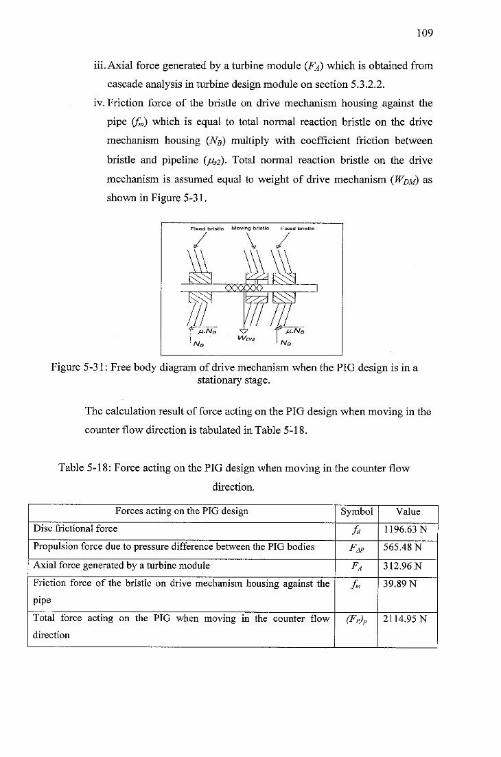
109
iii. Axial force generated by a turbine module (Fa) which is obtained from
cascade analysis in turbine design module on section 5.3.2.2.
iv. Friction force of the bristle on drive mechanism housing against the
pipe (fm) which is equal to total normal reaction bristle on the drive
mechanism housing (Nb) multiply with coefficient friction between
bristle and pipeline (/uS2). Total normal reaction bristle on the drive
mechanism is assumed equal to weight of drive mechanism (Wdm) as
shown in Figure 5-31.
Fixed brislle Moving bristle Fixed bristl
<xxxxx>
Figure 5-31: Free body diagram of drive mechanism when the PIG design is in astationary stage.
The calculation result of force acting on the PIG design when moving in the
counter flow direction is tabulated in Table 5-18.
Table 5-18: Force acting on the PIG design when moving in the counter flow
direction.
Forces acting on the PIG design Symbol Value
Disc frictional force U 1196.63 N
Propulsion force due to pressure difference between the PIG bodies Fap 565.48 N
Axial force generated by a turbine module FA 312.96 N
Friction force of the bristle on drive mechanism housing against the
pipe
Jm 39.89 N
Total force acting on the PIG when moving in the counter flow
direction
(Fp)p 2114.95 N
110
3. Bristle force analysis
i. Maximum axial force acts on a bristle (R 'a)
A bristle used in a drive mechanism module is considered as a strut
which is given by a compression load. Referring to design parameter of
bristle as defined in Table 5-17 and using safety factor of SF = 3,
maximum axial thrust force received by one bristle is estimated by
using equation 5.25 which gives Pcr—17.03 N. This value of maximum
of axial thrust force (PCr) is equal to the axial thrust force working on
the bristle when the bristle is push in reverse direction (R 'a).
ii. Ratio between bristle frictional force on reverse and forward direction
(Rrf)
A bristle has a unique characteristic which is easier to push in forward
direction rather than in reverse direction. Based on the design of design
parameter of bristle in Table 5-17, and using equation 5.34, the ratio
between bristle frictional force on reverse and forward direction (Rrf)
is estimated to be 4.28.
iii. Frictional force due to friction between the bristle on nut and pipeline
wall (f„)
A drive mechanism in the PIG design uses a unique characteristic of
the bristle which is easier to push in forward rather than in reverse
direction. A set of bristle is mounted on the nut which travels along a
double screw mechanism. To move in a counter flow direction, the
total friction force of bristle on nut with pipeline in reverse direction
(f'n) must be equal to the forces acting on the PIG when moving in a
counter flow direction (Fp)p.
The friction force of bristle on the nut with pipeline in reverse direction
(f'n) based on the estimation of load analysis, as shown in Table 5-18,
is 2114.95 N. Since a bristle has a unique characteristic which is easier
to move in forward rather than backward direction, the friction force of
bristle on the nut with pipeline in forward direction (fn) is obtained by
dividing the friction force of bristle on nut with pipeline in reverse
Ill
direction (/"'„) with ratio between the bristle frictional force on reverse
and forward direction (Rpf). Hence,_/^ = 494.6 N.
iv. Number of bristle required on a nut and drive mechanism housing
To find the number of bristle required on a nut and drive mechanism
housing, maximum axial thrust (R 'a) that can be received by a bristle
need to be converted into the friction force of bristle in reverse
direction (jLlR'n)- Referring to Figure 5-25, the relationship between
the maximum axial thrust (R'a) acting on a bristle with the friction
force of bristle in reverse direction (/u.R V) is
sinZEOD sinyy + cp)
Based on design parameters in Table 5-17 of bristle tip angle of y =
40°, friction angle perpendicular to the normal reaction force (Rn) of cp
—atan" (jigj) - 36.5 and the maximum axial thrust that can be received
by a bristle of R'a = 17.03 as calculated by using equation 5.25, the
friction force acts on a bristle in reverse direction (/mR V) is calculated
by using equation 5.42. Hence, piR V = 10.42 N.
The number of bristle required on a nut (CjB) is obtained by dividing
the total friction of bristle on nut in reverse direction (f'n) with the
friction force acting on one bristle in reverse direction (/u.R'n). It can
be stated in the following relationship:
/„ (5-43)^ bn ~
fi.R' N
Inserting value off'„= 2114.95 as defined in Table 5-18 and juR'n =
10.42 as calculated by using equation 5.42, the number of bristle
required on a nut is estimated by using equation 5.43. Thus, Cm is
approximately 204.
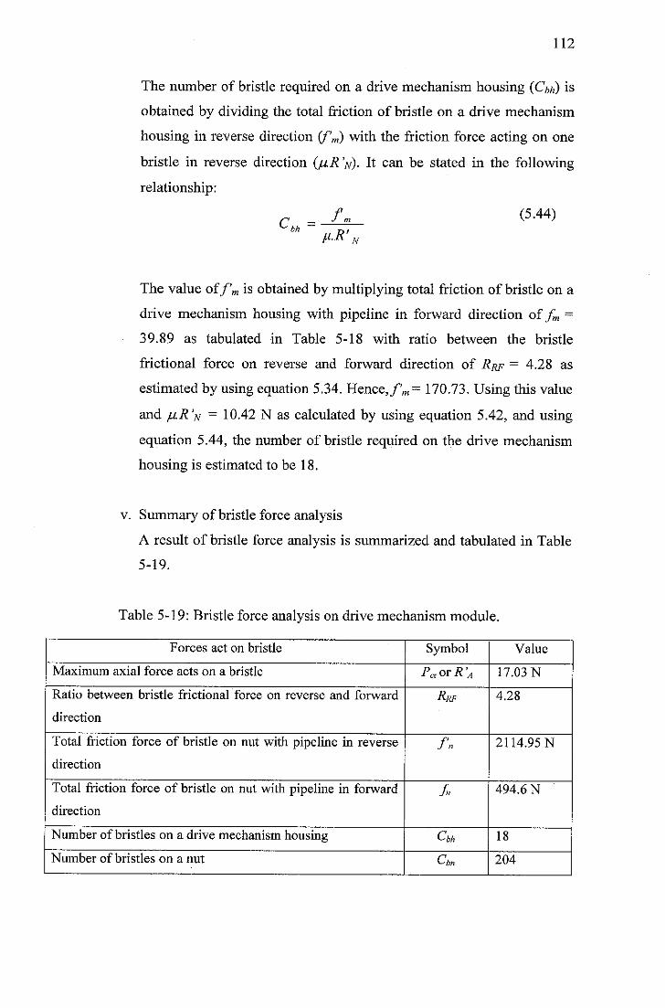
112
The number of bristle required on a drive mechanism housing (Cm) is
obtained by dividing the total friction of bristle on a drive mechanism
housing in reverse direction (f'm) with the friction force acting on one
bristle in reverse direction (/iR'n). It can be stated in the following
relationship:
cu.=f, (5.44)
M-R'„
The value off'm is obtained by multiplying total friction of bristle on a
drive mechanism housing with pipeline in forward direction offm =
39.89 as tabulated in Table 5-18 with ratio between the bristle
frictional force on reverse and forward direction of Rrf = 4.28 as
estimated by using equation 5.34. Hence,/'™ = 170.73. Using this value
and juR'N = 10.42 N as calculated by using equation 5.42, and using
equation 5.44, the number of bristle required on the drive mechanism
housing is estimated to be 18.
v. Summary of bristle force analysis
A result of bristle force analysis is summarized and tabulated in Table
5-19.
Table 5-19: Bristle force analysis on drive mechanism module.
Forces act on bristle Symbol Value
Maximum axial force acts on a bristle Pcvor R'A 17.03 N
Ratio between bristle frictional force on reverse and forward
direction
Rrf 4.28
Total friction force of bristle on nut with pipeline in reverse
direction
fn 2114.95 N
Total friction force of bristle on nut with pipeline in forward
direction
f 494.6 N
Number of bristles on a drive mechanism housing Cbh 18
Number of bristles on a nut Cbn 204
113
4. Power required by the drive mechanism
Characteristic of a drive mechanism module that consists of a nut and
double screw is intermittent motion. A nut needs to be travel to the end of
the double screw first and then the PIG design will start moving. A torque
required to drive a nut to travel to the end of the double screw and to drive
the PIG to move in a counter flow direction is different. Therefore analysis
of PIG motion is divided into two stages: nut moving and PIG design
moving.
i. PIG design moving
To move in a counter flow direction, a drive mechanism must provide
a propulsion force (Fr)p which is equal to summation of force acting
on the PIG design. Referring to a free body diagram of PIG design in
Figure 5-27, forces acting on the PIG design consist of disc frictional
force (fd), propulsion force due to pressure difference between the PIG
bodies (Fap), axial force generated by a turbine module (FA), friction
force of the bristle on drive mechanism housing against the pipeline
wall (fm), acceleration force of PIG (v p .mp) and viscous damping due
to the PIG moves through a liquid ((vp-vj).Dp). In analyzing of force
balance when PIG design moving, acceleration force of PIG (vp .mp)
and viscous damping due to the PIG moves through a liquid ((vp-
vj).Dp) is neglected due to small value compared to others force [9].
Based on this assumption, force balance equation when the PIG
moving in the equation 5.41 can be stated as:
(FB)P=ctg{x){Fp)p=l{FP)p (5'45)2n.rd
(FP)p = fm+L +FA+F
vp =(coDM)p.-—
where (Fb)p is reaction force on the thread, / is pitch of the screw, r^ is
radius of shaft, (FR)P is propulsion force generated by the thread, fm is
friction force of the bristle on drive mechanism housing against the
pipe, Fa is axial force generated by the turbine module, Fap is
AP
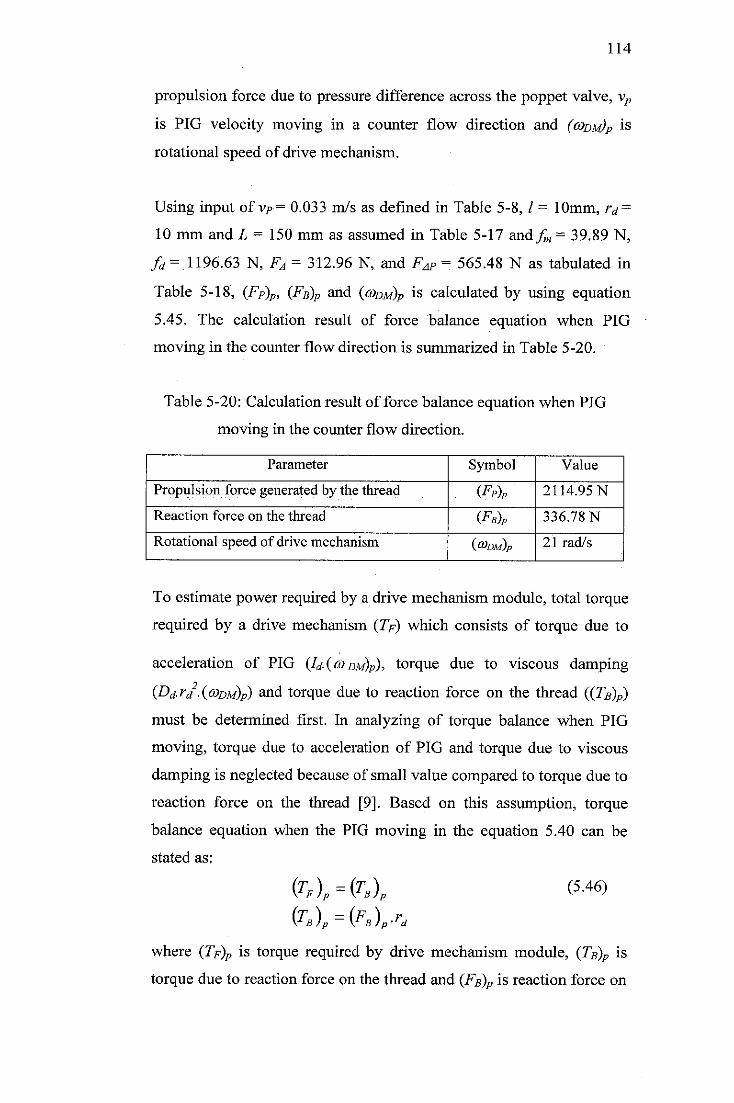
114
propulsion force due to pressure difference across the poppet valve, vp
is PIG velocity moving in a counter flow direction and (codm)p is
rotational speed of drive mechanism.
Using input of vR= 0.033 m/s as defined in Table 5-8, / = 10mm, /v =
10 mm and L = 150 mm as assumed in Table 5-17 andfm = 39.89 N,
fd= 1196.63 N, FA = 312.96 N, and Fap = 565.48 N as tabulated in
Table 5-18, (FP)P, (Fb)p and (g>dm)p is calculated by using equation
5.45. The calculation result of force balance equation when PIG
moving in the counter flow direction is summarized in Table 5-20.
Table 5-20: Calculation result of force balance equation when PIG
moving in the counter flow direction.
Parameter Symbol Value
Propulsion force generated by the thread (Ep)p 2114.95 N
Reaction force on the thread (Fb)p 336.78 N
Rotational speed of drive mechanism (g>dm)p 21 rad/s
To estimate power required by a drive mechanism module, total torque
required by a drive mechanism (7» which consists of torque due to
acceleration of PIG (Id. (codm)p), torque due to viscous damping
(Dd.rd .(codm)p) and torque due to reaction force on the thread ((TR)P)
must be determined first. In analyzing of torque balance when PIG
moving, torque due to acceleration of PIG and torque due to viscous
damping is neglected because of small value compared to torque due to
reaction force on the thread [9]. Based on this assumption, torque
balance equation when the PIG moving in the equation 5.40 can be
stated as:
{TF)P={TB)P (5-46)(TB)P={FB)p-rd
where (TF)P is torque required by drive mechanism module, (TB)P is
torque due to reaction force on the thread and (Fb)p is reaction force on
115
the thread and r<* is radius of shaft. Inserting value of (Fb)p = 336.78 N
as stated in Table 5-20 and ra = 10 mm as assumed in Table 5-17 into
equation 5.46, the torque required by drive mechanism module is 3.37
N.m.
Power required by the drive mechanism to provide a propulsion force
required by the PIG design is obtained from:
PDU=(TF)p.(a>DU)p (5-47)
where (Tf)p is torque required by drive mechanism module and (codm)p
is rotational speed of drive mechanism. Plugging value of (Tf)p —3.37
N.m. as calculated by using equation 5.46 and (codm)p = 21 rad/s as
described in Table 5-20 into equation 5.47, power required by the drive
mechanism is 71 Watt.
ii. Nut moving
To move in a counter flow direction, a nut on drive mechanism must
travel to the end of the double screw first. Propulsion forces required to
push a nut (Fp) must be equal to summation of friction force of bristle
on nut (fn), acceleration force of nut moving (vn.mn) and viscous
damping due to nut moving through a liquid ((vn-vj).Dn). In analyzing
of force balance when PIG moving, acceleration force of nut (v« .mn)
and viscous damping due to the PIG moves through liquid ((vn-Vf).Dn)
is neglected due to small value comparing to friction force of bristle on
nut (fn) [9]. Based on this assumption, force balance equation when the
nut moving in the equation 5.39 can be stated as:
FB - c* MF, - ^-.Fl (5'48)
Iv. = CO DM • -,
2,71
~> P2n.rd
where Fb is reaction force generated by the nut, / is pitch of the screw,
rd is radius of shaft, Fp is propulsion force generated by the thread,/ is
total friction force on nut with pipeline in forward direction, vn is
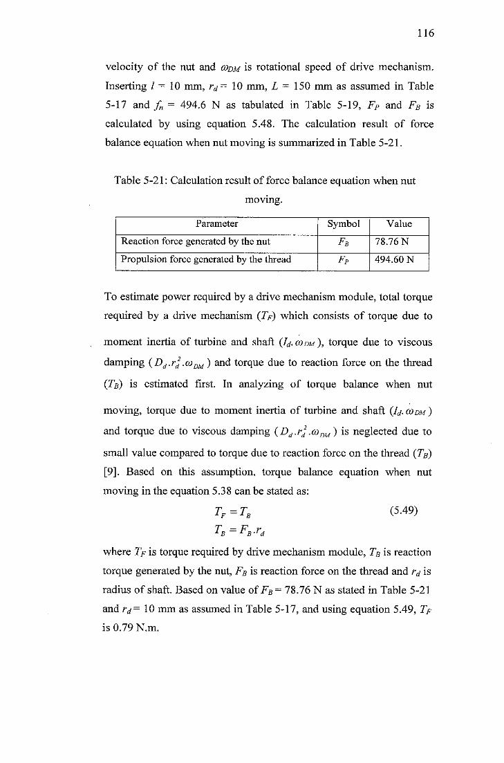
116
velocity of the nut and codm is rotational speed of drive mechanism.
Inserting / = 10 mm, /v= 10 mm, L = 150 mm as assumed in Table
5-17 and f„ = 494.6 N as tabulated in Table 5-19, FP and FB is
calculated by using equation 5.48. The calculation result of force
balance equation when nut moving is summarized in Table 5-21.
Table 5-21: Calculation result of force balance equation when nut
moving.
Parameter Symbol Value
Reaction force generated by the nut FB 78.76 N
Propulsion force generated by the thread FP 494.60 N
To estimate power required by a drive mechanism module, total torque
required by a drive mechanism (7>) which consists of torque due to
moment inertia of turbine and shaft (Id. codm ), torque due to viscous
damping (Dd.rj .coDM) and torque due to reaction force on the thread
(Tb) is estimated first. In analyzing of torque balance when nut
moving, torque due to moment inertia of turbine and shaft (Id.cooM)
and torque due to viscous damping (Dd.rd2.coDM) is neglected due to
small value compared to torque due to reaction force on the thread (Tb)
[9]. Based on this assumption, torque balance equation when nut
moving in the equation 5.38 can be stated as:
TF=TB
TB=FB-rd
(5.49)
where 7> is torque required by drive mechanism module, Tb is reaction
torque generated by the nut, Fb is reaction force on the thread and rd is
radius of shaft. Based on value of FB = 78.76 N as stated in Table 5-21
and rd= 10 mm as assumed in Table 5-17, and using equation 5.49, 7>
is 0.79 N.m.
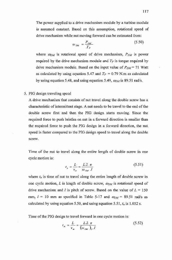
117
The power supplied to a drive mechanism module by a turbine module
is assumed constant. Based on this assumption, rotational speed of
drive mechanism while nut moving forward can be estimated from:
_ PDM (5-50)co DM ~ j.
F
where codm is rotational speed of drive mechanism, Pdm is power
required by the drive mechanism module and 7> is torque required by
drive mechanism module. Based on the input value of Pdm = 71 Watt
as calculated by using equation 5.47 and 7> = 0.79 N.m as calculated
by using equation 5.48, and using equation 5.49, codm is 89.51 rad/s.
5. PIG design traveling speed
A drive mechanism that consists of nut travel along the double screw has a
characteristic of intermittent stage. A nut needs to be travel to the end of the
double screw first and then the PIG design starts moving. Since the
required force to push bristles on nut in a forward direction is smaller than
the required force to push the PIG design in a forward direction, the nut
speed is faster compared to the PIG design speed to travel along the double
screw.
Time of the nut to travel along the entire length of double screw in one
cycle motion is:
_ L _ L.2. K (5.51)
V» &DM-1
where tn is time of nut to travel along the entire length of double screw in
one cycle motion, L is length of double screw, codm is rotational speed of
drive mechanism and / is pitch of screw. Based on the value of L = 150
mm, / = 10 mm as specified in Table 5-17 and codm — 89.51 rad/s as
calculated by using equation 5.50, and using equation 5.51, tn is 1.052 s.
Time of the PIG design to travel forward in one cycle motion is:
L L.2.% (5.52)t„ =
Vn, fa DM )P-l
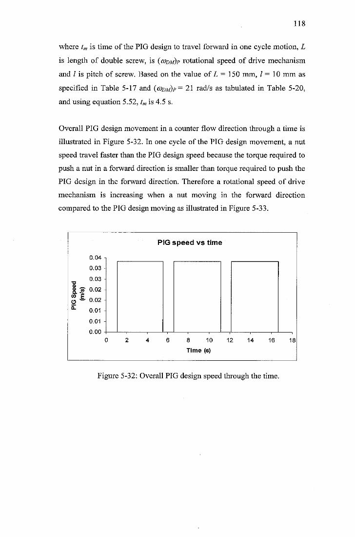
118
where tm is time of the PIG design to travel forward in one cycle motion, L
is length of double screw, is (codm)p rotational speed of drive mechanism
and / is pitch of screw. Based on the value of L = 150 mm, / = 10 mm as
specified in Table 5-17 and (codm)p= 21 rad/s as tabulated in Table 5-20,
and using equation 5.52, tm is 4.5 s.
Overall PIG design movement in a counter flow direction through a time is
illustrated in Figure 5-32. In one cycle of the PIG design movement, a nut
speed travel faster than the PIG design speed because the torque required to
push a nut in a forward direction is smaller than torque required to push the
PIG design in the forward direction. Therefore a rotational speed of drive
mechanism is increasing when a nut moving in the forward direction
compared to the PIG design moving as illustrated in Figure 5-33.
0.04 ->
0.03 -
0.03
| -3T 0.02%£ 0.02°" 0.01
0.01 H
0.00
0
PIG speed vs time
8 10
Time (s)
12 14 16
Figure 5-32: Overall PIG design speed through the time.
18
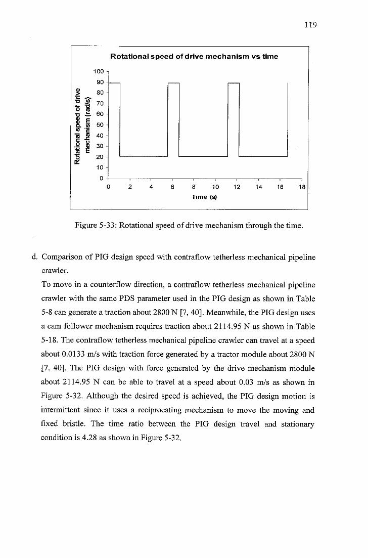
•o
co
I
I
Rotational speed of drive mechanism vs time
100 i
90
80
70
60
50
40
30 H
20
10
8 10
Time (s)
12 14 16
119
18
Figure 5-33: Rotational speed of drive mechanism through the time.
d. Comparison of PIG design speed with contraflow tetherless mechanical pipeline
crawler.
To move in a counterflow direction, a contraflow tetherless mechanical pipeline
crawler with the same PDS parameter used in the PIG design as shown in Table
5-8 can generate a traction about 2800 N [7, 40]. Meanwhile, the PIG design uses
a cam follower mechanism requires traction about 2114.95 N as shown in Table
5-18. The contraflow tetherless mechanical pipeline crawler can travel at a speed
about 0.0133 m/s with traction force generated by a tractor module about 2800 N
[7, 40]. The PIG design with force generated by the drive mechanism module
about 2114.95 N can be able to travel at a speed about 0.03 m/s as shown in
Figure 5-32. Although the desired speed is achieved, the PIG design motion is
intermittent since it uses a reciprocating mechanism to move the moving and
fixed bristle. The time ratio between the PIG design travel and stationary
condition is 4.28 as shown in Figure 5-32.
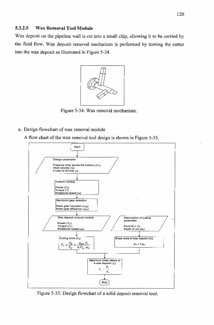
120
5.3.2.5 Wax Removal Tool Module
Wax deposit on the pipeline wall is cut into a small chip, allowing it to be carried by
the fluid flow. Wax deposit removal mechanism is performed by turning the cutter
into the wax deposit as illustrated in Figure 5-34.
Figure 5-34: Wax removal mechanism.
a. Design flowchart of wax removal module
A flow chart of the wax removal tool design is shown in Figure 5-35.
Start
Design parameter
Pressure drop across the turbine (APT)Fluid velocity (V,)Crude oil density (p)
Turbine module
Power (PT)Torque (T)Rotational speed (ta)
Harmonic gear selection
Ratio gear reduction (nHD)Ratio gear efficiency (^Hd)
Wax deposit removal module
Power (/V)Torque (7V)Rotational speed (ais)
Assumption of cuttingparameter
Feed (f) = VPDepth of cut (d„)
Cutting force (Fc)
— w _ t?/fD-"rVw JT.DM.Q}3
Fr =
Shear area of wax deposit (As)
As = f.dw
Maximum shear stress of
a wax deposit (r^)
Ft, =—£~
(stop]
Figure 5-35: Design flowchart of a solid deposit removal tool.
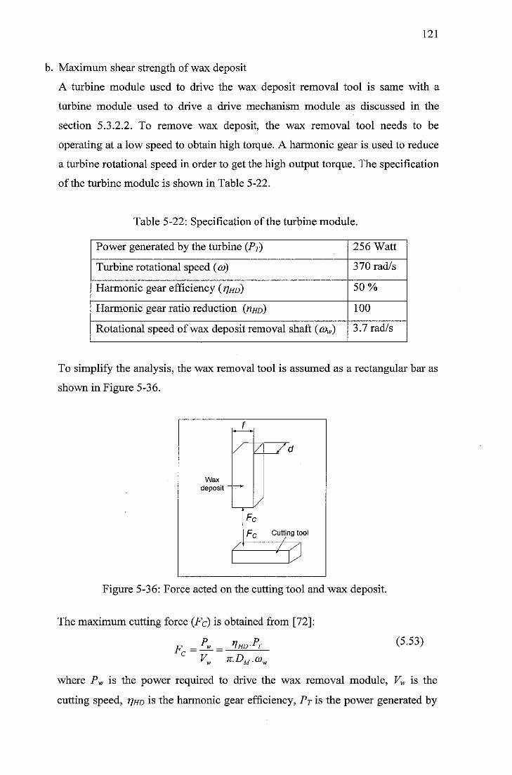
121
b. Maximum shear strength of wax deposit
A turbine module used to drive the wax deposit removal tool is same with a
turbine module used to drive a drive mechanism module as discussed in the
section 5.3.2.2. To remove wax deposit, the wax removal tool needs to be
operating at a low speed to obtain high torque. A harmonic gear is used to reduce
a turbine rotational speed in order to get the high output torque. The specification
of the turbine module is shown in Table 5-22.
Table 5-22: Specification of the turbine module.
Power generated by the turbine (Pr) 256 Watt
Turbine rotational speed (co) 370 rad/s
Harmonic gear efficiency (t/hd) 50%
Harmonic gear ratio reduction (nno) 100
Rotational speed of wax deposit removal shaft (co^) 3.7 rad/s
To simplify the analysis, the wax removal tool is assumed as a rectangular bar as
shown in Figure 5-36.
Wax
deposit -
h f -
Zl / _Zd
/
1'~ Cutting tool
/ / A7 )
Figure 5-36: Force acted on the cutting tool and wax deposit.
The maximum cutting force (Fc) is obtained from [72]:
P.. Vhd-FtFc =
K. *-£>m-o>»
(5.53)
where Pw is the power required to drive the wax removal module, Vw is the
cutting speed, tjhd is the harmonic gear efficiency, Pp is the power generated by
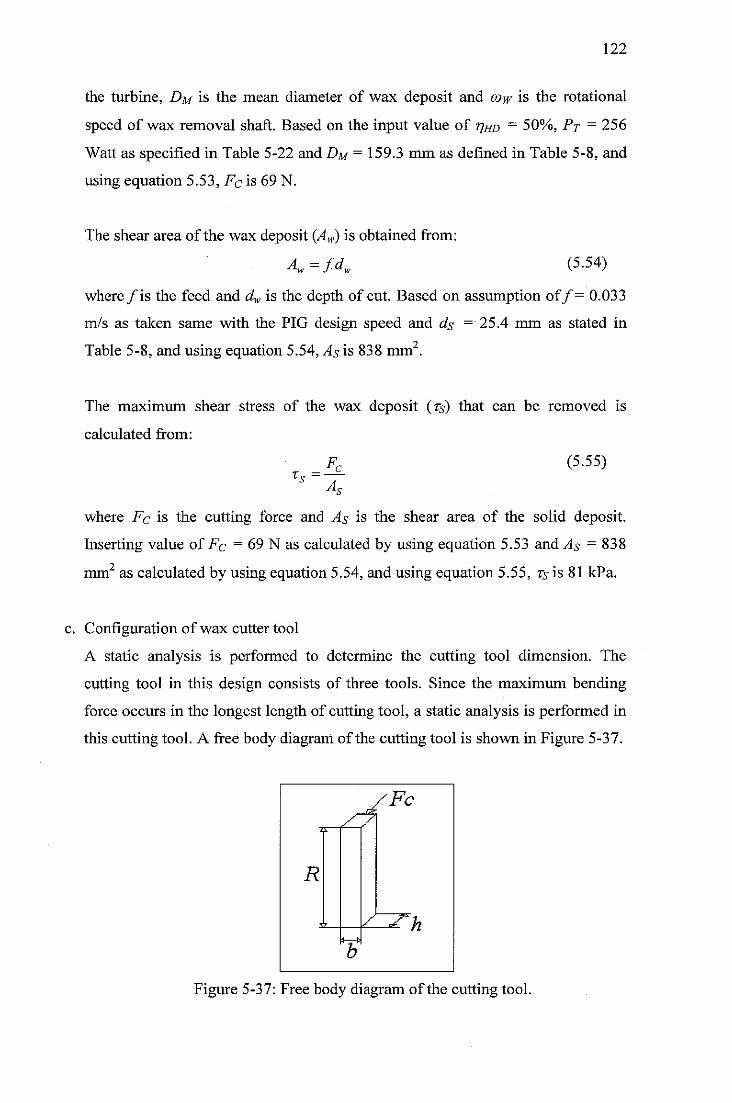
122
the turbine, Dm is the mean diameter of wax deposit and cow is the rotational
speed of wax removal shaft. Based on the input value of 77^0 - 50%, Pp = 256
Watt as specified in Table 5-22 and Dm = 159.3 mm as defined in Table 5-8, and
using equation 5.53, Fc is 69 N.
The shear area of the wax deposit (Aw) is obtained from:
A„=fdw (5.54)
where/is the feed and dw is the depth of cut. Based on assumption of/= 0.033
m/s as taken same with the PIG design speed and ds ='25A mm as stated in
Table 5-8, and using equation 5.54, As is 838 mm .
The maximum shear stress of the wax deposit (ts) that can be removed is
calculated from:
Fc (5.55)rs =
A
where Fc is the cutting force and As is the shear area of the solid deposit.
Inserting value of Fc = 69 N as calculated by using equation 5.53 and As = 838
mm as calculated by using equation 5.54, and using equation 5.55, Ts is 81 kPa.
c. Configuration of wax cutter tool
A static analysis is performed to determine the cutting tool dimension. The
cutting tool in this design consists of three tools. Since the maximum bending
force occurs in the longest length of cutting tool, a static analysis is performed in
this cutting tool. A free body diagram ofthe cutting tool is shown in Figure 5-37.
Figure 5-37: Free body diagram of the cutting tool.
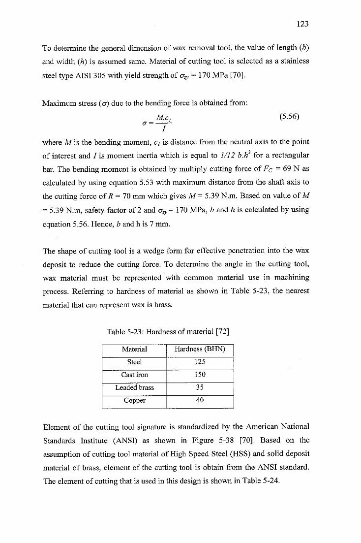
123
To determine the general dimension of wax removal tool, the value of length (b)
and width (h) is assumed same. Material of cutting tool is selected as a stainless
steel type AISI 305 with yield strength of o^ - 170 MPa [70].
Maximum stress (cr) due to the bending force is obtained from:
M.c}a —
I
(5.56)
where M is the bending moment, cj is distance from the neutral axis to the point
of interest and / is moment inertia which is equal to 1/12 b.h3 for a rectangular
bar. The bending moment is obtained by multiply cutting force of Fc = 69 N as
calculated by using equation 5.53 with maximum distance from the shaft axis to
the cutting force of R - 70 mm which gives M= 5.39 N.m. Based on value of M
= 5.39 N.m, safety factor of 2 and crsy= 170 MPa, b and h is calculated by using
equation 5.56. Hence, b and h is 7 mm.
The shape of cutting tool is a wedge form for effective penetration into the wax
deposit to reduce the cutting force. To determine the angle in the cutting tool,
wax material must be represented with common material use in machining
process. Referring to hardness of material as shown in Table 5-23, the nearest
material that can represent wax is brass.
Table 5-23: Hardness of material [72]
Material Hardness (BHN)
Steel 125
Cast iron 150
Leaded brass 35
Copper 40
Element of the cutting tool signature is standardized by the American National
Standards Institute (ANSI) as shown in Figure 5-38 [70]. Based on the
assumption of cutting tool material of High Speed Steel (HSS) and solid deposit
material of brass, element of the cutting tool is obtain from the ANSI standard.
The element of cutting that is used in this design is shown in Table 5-24.
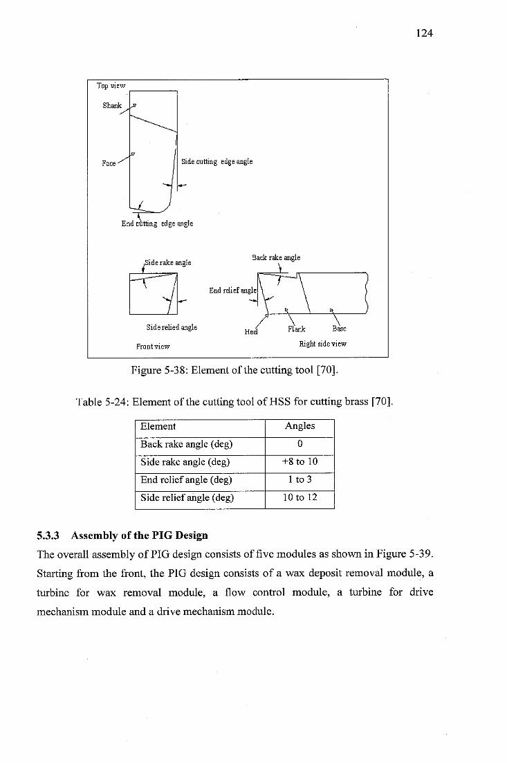
Top view-
Shank •»
Face^DSidecutting edgeangle
End cutting edge angle
.Side rake. Back rake angle
angle . s
,
^J End relief angleV \7 ** V , \ H )
Siderelie 3angle Heel Flank Base
Front view **&& side view
Figure 5-38: Element of the cutting tool [70].
Table 5-24: Element of the cutting tool of HSS for cutting brass [70].
Element Angles
Back rake angle (deg) 0
Side rake angle (deg) +8 to 10
End relief angle (deg) 1 to 3
Side relief angle (deg) 10 to 12
124
5.3.3 Assembly of the PIG Design
The overall assembly of PIG design consists of five modules as shown in Figure 5-39.
Starting from the front, the PIG design consists of a wax deposit removal module, a
turbine for wax removal module, a flow control module, a turbine for drive
mechanism module and a drive mechanism module.
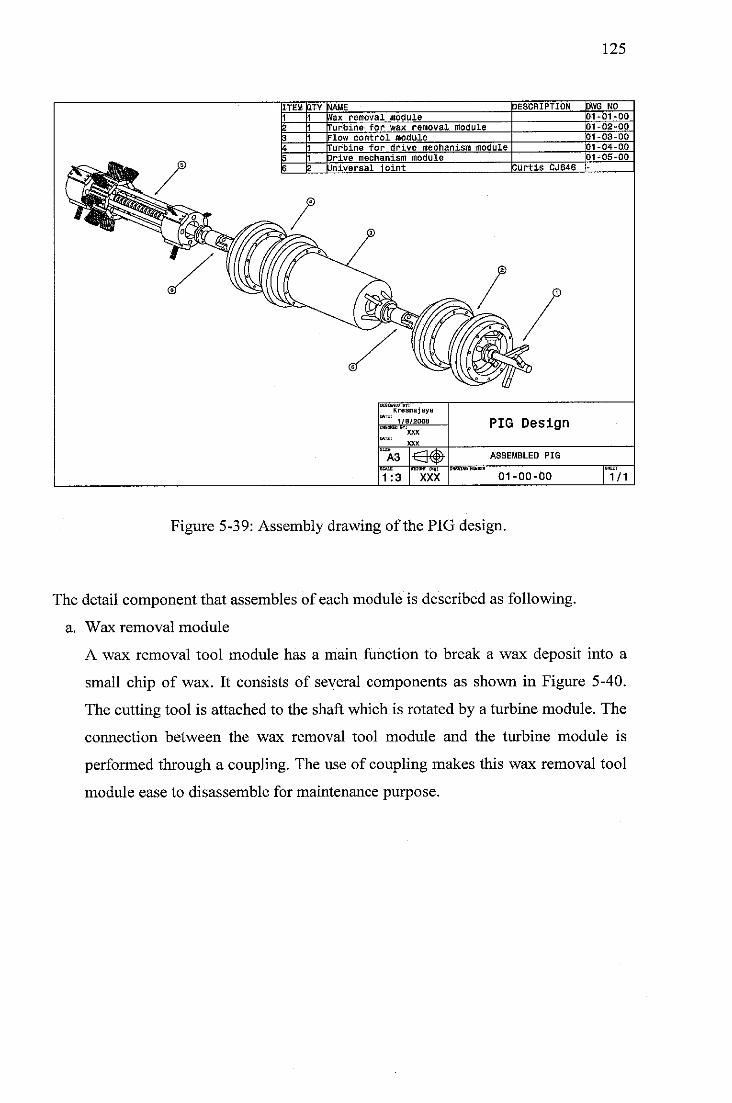
125
^^Jfcab ?
ITEM JTY \IAME DESCRIPTION 3WG NO
1 Vax removal module 31-01-00
a Turbine for wax removal module 31-02-00
3 -low control module 31-03-00
* Turbine for drive mechanism module 31-04-00
5 i 3rive mechanism module 31-05-00
3 ? Jniversal joint SurtiS CJ646 -
LJESIDNED DT!
Kresnajaya
1/B/2008 PIG DesignXXX
XXX
A3 r~lfrr?) ASSEMBLED PIG^"^
1:3 XXX 01-00-00 1/1
Figure 5-39: Assembly drawing of the PIG design.
The detail component that assembles of each module is described as following,
a. Wax removal module
A wax removal tool module has a main function to break a wax deposit into a
small chip of wax. It consists of several components as shown in Figure 5-40.
The cutting tool is attached to the shaft which is rotated by a turbine module. The
connection between the wax removal tool module and the turbine module is
performed through a coupling. The use of coupling makes this wax removal tool
module ease to disassemble for maintenance purpose.
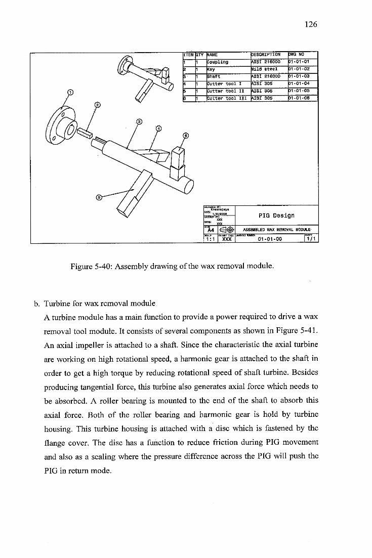
126
ASSEMBLED WAX REMOVAL MODULE
7mT
XXX 01-01-00
Figure 5-40: Assembly drawing of the wax removal module.
BlffET
1/1
b. Turbine for wax removal module
A turbine module has a main function to provide a power required to drive a wax
removal tool module. It consists of several components as shown in Figure 5-41.
An axial impeller is attached to a shaft. Since the characteristic the axial turbine
are working on high rotational speed, a harmonic gear is attached to the shaft in
order to get a high torque by reducing rotational speed of shaft turbine. Besides
producing tangential force, this turbine also generates axial force which needs to
be absorbed. A roller bearing is mounted to the end of the shaft to absorb this
axial force. Both of the roller bearing and harmonic gear is hold by turbine
housing. This turbine housing is attached with a disc which is fastened by the
flange cover. The disc has a function to reduce friction during PIG movement
and also as a sealing where the pressure difference across the PIG will push the
PIG in return mode.
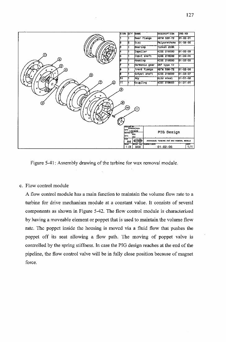
127
ITEM QTY 4AME DESCRIPTION WG NO
1 1 lear flange USTM 536-72 )1-02-01
2 2 Jisc 'olyurethane 01-02-02
3 1 Searing rimken 200K-
4 [mpeller MSI 216000 01-02-03
i [nput shaft MSI 216000 01-02-04
3 1 •lousing MSI 216000 01-02-05
7 1 Harmonic gear JSF type 17-
i :ront flange \STM 538-72 01-02-08
3 Output shaft MSI 216000 01-02-07
10 Key Aild steel 01-01-02
11 [ Coupling AISI 216000 01-01-01
PIG Design
ASSEMBLED TURBINE FOR WAX REMOVAL MODULE
01-02-00
Figure 5-41: Assembly drawing of the turbine for wax removal module.
•3HS—
1/1
c. Flow control module
A flow control module has a main function to maintain the volume flow rate to a
turbine for drive mechanism module at a constant value. It consists of several
components as shown in Figure 5-42. The flow control module is characterized
by having a moveable element or poppet that is used to maintain the volume flow
rate. The poppet inside the housing is moved via a fluid flow that pushes the
poppet off its seat allowing a flow path. The moving of poppet valve is
controlled by the spring stiffness. In case the PIG design reaches at the end of the
pipeline, the flow control valve will be in fully close position because of magnet
force.
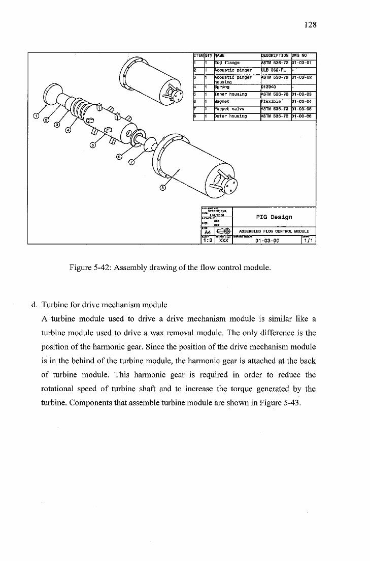
128
ASSEMBLED FLOW CONTROL MODULE
prEiattT"(fcij7
XXX 01-03-00
Figure 5-42: Assembly drawing of the flow control module.
SBEeT—
1/1
d. Turbine for drive mechanism module
A turbine module used to drive a drive mechanism module is similar like a
turbine module used to drive a wax removal module. The only difference is the
position of the harmomc gear. Since the position of the drive mechanism module
is in the behind of the turbine module, the harmonic gear is attached at the back
of turbine module. This harmonic gear is required in order to reduce the
rotational speed of turbine shaft and to increase the torque generated by the
turbine. Components that assemble turbine module are shown in Figure 5-43.
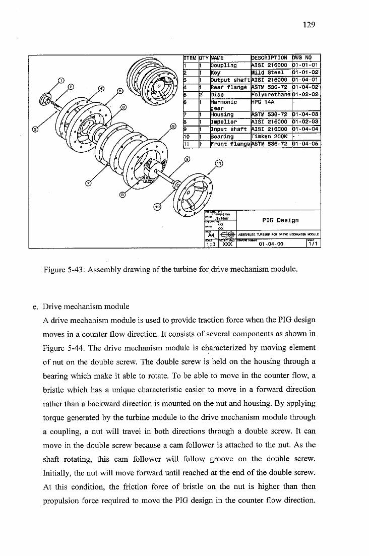
129
Figure 5-43: Assembly drawing of the turbine for drive mechanism module.
e. Drive mechanism module
A drive mechanism module is used to provide traction force when the PIG design
moves in a counter flow direction. It consists of several components as shown in
Figure 5-44. The drive mechanism module is characterized by moving element
of nut on the double screw. The double screw is held on the housing through a
bearing which make it able to rotate. To be able to move in the counter flow, a
bristle which has a unique characteristic easier to move in a forward direction
rather than a backward direction is mounted on the nut and housing. By applying
torque generated by the turbine module to the drive mechanism module through
a coupling, a nut will travel in both directions through a double screw. It can
move in the double screw because a cam follower is attached to the nut. As the
shaft rotating, this cam follower will follow groove on the double screw.
Initially, the nut will move forward until reached at the end of the double screw.
At this condition, the friction force of bristle on the nut is higher than then
propulsion force required to move the PIG design in the counter flow direction.
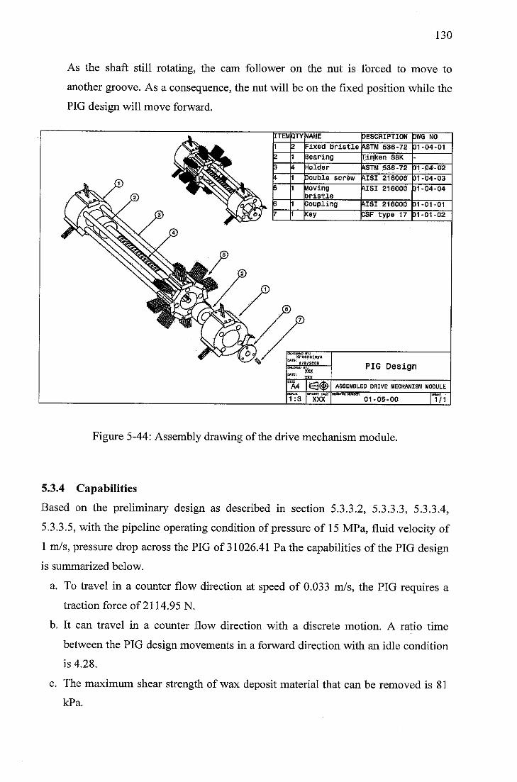
130
As the shaft still rotating, the cam follower on the nut is forced to move to
another groove. As a consequence, the nut will be on the fixed position while the
PIG design will move forward.
Figure 5-44: Assembly drawing of the drive mechanism module.
5.3.4 Capabilities
Based on the preliminary design as described in section 5.3.3.2, 5.3.3.3, 5.3.3.4,
5.3.3.5, with the pipeline operating condition of pressure of 15 MPa, fluid velocity of
1 m/s, pressure drop across the PIG of 31026.41 Pa the capabilities of the PIG design
is summarized below.
a. To travel in a counter flow direction at speed of 0.033 m/s, the PIG requires a
traction force of 2114.95 N.
b. It can travel in a counter flow direction with a discrete motion. A ratio time
between the PIG design movements in a forward direction with an idle condition
is 4.28.
c. The maximum shear strength of wax deposit material that can be removed is 81
kPa.
131
5.3.5 Limitation
The PIG design has still limitation on its design and it is summarized below.
a. The PIG design is currently design based on the data from literature review. A
prototype of the proposed PIG design needs to be manufactured and test to
validate the calculation.
b. The PIG design only can berespond with fluid flow variation since it is designed
based on perpetual mechanism. If the pipeline consists of obstruction like a
reduced valve such as gate and butterfly, the PIG design is in the riskto get stuck
inside a pipeline.
5.3.6 The Difference with Contraflow Tetherless Mechanical Pipeline Crawler
DPT Crawler
The PIG design consists of combination from the contraflow tetherless mechanical
pipeline crawler and the DPT crawler. Since the main requirement
is to be able to travel at a desired speed of 0.033 m/s, a cam follower mounted with
bristle is the most promising one. Eventhough this mechanism creates an intermittent
motion by sacrificing the secondary requirement to travel at a continuous motion, the
traveling speed generated by this driving mechanism is better than an offset bearing
mechanism as discussed in the section 5.3.3.4. For the wax removal mechanism, the
PIG design uses the cutting tool module as used in the contraflow tetherless
mechanical pipeline crawler. This cutting tool module uses an active force which is
generated by a turbine module. It makes the wax deposit is cut into a small chip of
wax which is able to be carried by the fluid flow. Comparing to the DPT crawler, it
uses a scraping mechanism by pushing the bristle through the wax solid deposit. As a
consequence, some of wax chip removal will accumulate in front of the DPT. In order
to move at a constant speed for increasing the wax cleaning efficiency, the PIG design
is equipped with the flow control module which consists of a poppet valve and a
spring mechanism. This mechanism is almost same which is used in the contraflow
tetherless mechanical pipeline crawler. The difference is to trigger in the close
position, the flow control module in the PIG uses a magnet mechanism. The benefits
of using this mechanism is a perpetual mechanism which ensures the capability of the
PIG design to travel through the entire lengthof the pipeline.
132
CHAPTER SIX: CONCLUSION AND RECOMMENDATIONS
6.1 Introduction
Chapter six is organized into two sections. The first section provides conclusion of the
result in this research. The second section describes some recommendations for the
future work.
6.2 Conclusion
The research work has produced a CAD model of contraflow PIG which has function
to clean wax from pipeline. The proposed PIG concept consists of an axial turbine as
a power source, a cutter tool as a wax removal tool, a poppet valve as a flow control, a
cam follower as a drive mechanism and an acoustic pinger as PIG locating is
proposed to be further developed in the embodiment phase.
Further, the physical element of each functions are classified into five modules which
determines the product architecture of PIG design. It consists of turbine module to
drive a drive mechanism module, a drive mechanism module, a flow control module,
a turbine to drive wax removal module, and a wax removal module. Based on the
preliminary analysis, with the pipeline operating condition of pressure of 15 MPa,
fluid velocity of 1 m/s, pressure drop across the PIG of 31 kPa the capabilities of PIG
design is summarized below.
a. To travel in a counter flow direction at a specified speed of 0.033 m/s, the PIG
requires a traction force of 2114.95 N.
b. It can travel in a counter flow direction with a discrete motion at a time ratio of
4.28 between the PIG design movements in forward direction and the stationarycondition.
c. It canremove wax deposit on the offshore pipeline with maximum shear strength
of81kPa.
133
6.3 Recommendations
This project consists of several phases to develop a PIG design for offshore pipeline
maintenance into functional prototypes. The preliminary results obtained at the end of
this project relates to the configuration design phase. A preliminary calculation of PIG
design has been done with reference to the PDS document, but future work would
certainly lead to an improvement to this design.
First, as described previously, because of time constraint, lot of assumptions were
made in order to achieve the objectives of the research work. The accuracy of the
result could be improved by checking those assumptions. The most important
assumptions that should be checked are friction force generated by the bristle with
pipeline, friction force generated between the disc and the pipeline wall, and shear
stress of wax. Further study on this subject could bring more accurate result on the
PIG design performance.
For future work, it could be interesting to investigate the effect on cutting tool angle
with machining parameter used to break wax deposit into a small chip of wax. It may
be thought that the cutting tool angle would have been different from the one used
here and the resulting design would be able to remove wax with higher shear stress by
using the same power input from turbine design.
Furthermore, the prototype of the proposed PIG design should be manufactured and
tested. To check the accuracy with preliminary design as comparison, it is
recommended that every module should be fabricated and tested separately at first.
Then, if there is a large different in the result with the preliminary design and
prototype testing is found, a redesign analysis of module should be performed before
doing the prototype testing again. Finally, the complete assembly of PIG prototype is
to be tested and verified against the desired accuracy of the preliminary design.
134
REFERENCES
[1] N. Khalid, "Deepwater Developments in Malaysia : Searching for Energy inthe Wild Frontiers," in 2nd PetroMin Underwater Technology Conference2006, pp. 1-11.
[2] W. L. Leffler, R. Pattarozzi, and G. Sterling, Deepwater: PetroleumExploration & Production - A Nontechnical Guide. Tulsa, Oklahama:PennWell Books, 2003.
[3] B. Stoltze, "A New Pipeline Cleaning Technology: Hydraullicaly ActivatedPower Pigging (HAAP™)," in PPSA Aberdeen Seminar 2006, pp. 1-6.
[4] E. J. Dewar and G. L. Smith, "Progessive Pigging for Pipeline DepositRemoval," in Pipeline Pigging and Integrity Monitoring Conference, 1994,pp. 1-8.
[5] J. N. H. Tiratsoo, Pipeline Pigging Technology. Houston, Texas, USA: GulfPublishing Company, 1991.
[6] R. Schmidt, "Unpiggable Pipelines - What a Challenge for In-line Inspection,"in PPSA Aberdeen Seminar 2004.
[7] S. D'Axcy, B. Newman, and G. Broze, "A Contraflow Tetherless MechanicalPipeline Crawler," in Offshore Technology Conference, OTC 15259, 2003, pp1-8.
[8] N. Stephenson, "Emerging Issues of the Next 10-20 Years," in PPSAAberdeen Seminar, 2004.
[9] Z. Hu and E. Appleton, "Dynamic Characteristics of a Novel Self-DrivePipeline Pig," IEEE Transactions on Robotics, vol. 21, 2005, pp. 781-789.
[10] G. E. Dieter, Engineering Design: A Materials and Processing Approach,Third ed. Singapore: McGrawHill, 2000.
[11] A. Amin, M. Riding, R. Shepler, and E. Smedstad, "Subsea Development fromPore to Process," 23th January 2007,http://www.slb.com/media/services/resources/oilfieldreview/ors05/sT3r05/01 subsea development.pdf.
[12] B. Guo, S. Song, J. Chacko, and A. Ghalambor, Offshore Pipelines. Oxford,UK: Gulf Profesional Publishing, 2005.
[13] F. K. Wasden, "Flow Assurance in Deepwater Flowlines and Pipelines -Challenges Met, Challenges Remaining," in Offshore Technology Conference,OTC 15184, 2003, pp. 1-3.
[14] R. Venkatesan, N. R. Nagarajan, K. Paso, Y.-B. Yi, A. M. Sastry, and H. S.Fogler, "The Strength of Paraffin Gels Formed Under Static and FlowConditions," Chemical Engineering Science, Elsevier, vol. 60, 2005, pp. 3587-3598.
[15] E. D. S. Jr. and J. B. Bloys, Hydrate Engineering. Richardson, Texas: SPEInc. , 2000.
[16] M. Hyodo, A. F. L. Hyde, Y. Nakata, N. Yoshimoto, M. Fukunaga, K. Kubo,Y. Nanjo, T. Matsuo, and K. Nakamura, "Triaxial Compressive Strength ofMethane Hydrate," in Proceedings of The Twelfth (2002) InternationalOffshore andPolarEngineering Conference, 2002,pp. 422-428.
[17] P. Fretwell, "Developments in Mechanical Production Cleaning of Pipelines,"in PPSA Aberdeen Seminar, 2007.
135
[18] A. C. F. Lino, F. B. Pereira, and M. G. F. M. Gomes, "DevelopingTechniques, Facilities for Deepwater Flowline Pigging," in Pipeline & GasIndustry, 1995.
[19] E. D. Sloan and J. B. Bloys, Hydrate Engineering. Richardson, Texas: SPEInc., 2000.
[20] PPSA, An Introduction to Pipeline PIGGING. Beaconsfield, UK- PipelineWorld, 1993.
[21] J. Quarini and S. Shire, "A review of fluid-driven pipeline pigs and theirapplications," Proc. IMechE Part E: J. Process Mechanical Engineering, vol.221, 2006, pp. 1-10.
[22] Girard Industry, "Girard Product Line," 15th July 2008,http://www.girardind.com/ourProducts.cfm.
[23] Pigs Unlimited Inc., "Spare Components," 18th July 2007,http://www.pigsunlimited.com.
[24] Apache, "Spare Components," July 2007, http://www.apachepipe.com.[25] BS 8010-3, Code of Practice for Pipelines — Part 3: Pipelines Subsea:
Design, Construction and Installation, 1993.[26] Q. Wang, C. Sarica, and T. X. Chen, "An Experimental Study on Mechanics
of Wax Removal in Pipeline," Journal ofEnergy Resources Technology vol127, 2005, pp. 302-309.
[27] G. C. Short, "The Pigging Technology Project: The First Three Years," inPipes and Pipelines International, 1994.
[28] C. Yardi, "Design of Regulated Velocity Flow Assurance for the PetroleumIndustry," M. S. thesis, Texas A&MUniversity, Texas, US, 2003
[29] R. Torbin, "Advanced Inspection Robot for Unpiggable Pipelines," in AGAOperations Conference, 2006.
[30] C. Falck, C. Svendsen, and A. O'Donoghue, "Multi diameter pigging forAsgard: Commissioning and pigging the 710km 42" x 28" Asgard Pipeline,"in OPTConference, 2000, pp. 1-16.
[31] E. Gjertveit, K. Sjoen, and L. O. Eide, "Innovations Push Asgard Transport,"in Oil & GasJournal, vol. 99 2001, pp. 50-54.
[32] W. Furlow, "Smart Pig Technology Focuses on One-way Pipe Applications,"in Oil & Gas Journal, vol. 59 1999.
[33] API, Design, Construction, Operation & Maintenance of OffshoreHydrocarbon Pipelines (Limit State Design), Third Edition ed. Washington,US: API Publishing Services, 2000.
[34] G. E. Lochte, "Deepwater Economics How Pigging Operatios ImpactDeepwaterProductionEconomics," in Offshore, vol. 55, 1995.
[35] I. Fraser, A. Duff, and C. Falck, "Engineer Master Challenges to CommissionLarge Vietnam Pipeline," in Pipeline & Gas Journal, vol. August 2003, pp.30-32.
[36] Oceaneering International, "New Technology Applications for Gas Pipelines,"10th July 2006, http://www.angda.state.ak.us.
[37] Anonymous, "Unpiggable Pipelines: Things of the past?," in Offshore, vol. 642004.
[38] G. Short and M. Elliott, "New Methods of Inspecting and MaintainingOperational Oil and Gas Pipelines," in PetroMin 2nd Pipeline Conference2003, pp.1-15.
[39] N. A. A. Simpson, "Bidirectional Traction Apparatus," US 6,953,086 B2, Oct.11,2005.
136
[40] C. Stanley, "Contraflow Tetherless Mechanical Pipeline Crawler," inProceeding ofPipeline Pigging, Integrity Assessment andRepair Conference,2004, pp. 1-12.
[41] E. Appleton and N. W. Stutchbury, "Conduit Traversing Vehicle," US Patent6,769,321 Bl,2004.
[42] K. Boe and Fana, "Pipeline PIG," US 2007/0214590 Al, 2007.[43] F. H. Ghorbel and J. B. Dabney, "Autonomous Robotic Crawler for In-Pipe
Inspection," US 7,182,025 B2, 2007.[44] K. Plantenberg, "An Introduction To Catia V5, Release 12," Schroff
Development Corporation, 2004.[45] Fluent Inc., "Tutorial 8. Using Multiple Rotating Reference Frames," 5th
January 2008, http://www.fluent.com.[46] K. T. Ulrich and S. D. Eppinger, Product Design and Development, 3rd ed.
New York, US: McGraw Hill, 2004.[47] D. G. Ullman, The Mechnanical Design Process, 2nd ed. Singapore: McGraw-
Hill Companies, Inc., 1997.[48] G. Pahl and W. Beitz, Engineering Design: A systematic Design Approach,
2nded, 1995.[49] T. Wright, FluidMachinery: Performance, Analysis andDesign. Florida, US:
CRC Press, 1999.[50] S. Hirose, H. Ohno, T. Mitsui, and K. Suyama, "Design of In-Pipe Inspection
Vehicles for §25, <j>50, §150 pipes," in Proceeding of the 1999 InternationalConference on Robotics &Automation, 1999, pp. 2309-2314.
[51] Pipeline Engineer, "Distributor Manual," 15th January 2007,http://www.pipelineengineering.com.
[52] D. C. Campbell, "Variable Speed for Pipeline PIG," U.S. Patent 5,208,936,May 11, 1993.
[53] I. Smith, P. A. Couchman, and B. K. C. Jones, "Pipeline PIGS," U.S. Patent6,098,231, August 8, 2000.
[54] G. R. Marshall, "Cleaning the Valhall Offshore Oil Pipeline," in OffshoreTechnology Conference, SPE 17880, 1990,pp. 275-278.
[55] R. H. Bishop, Mechatronics: An Introduction. New York, US: CRC Press,Taylor and Francis Group, 2006.
[56] R. K. Riddell, "Pig Tracking in Subsea Pipelines: Developments and FieldExperiences," in Pipeline PiggingandIntegrity Monitoring Conference, 1994,pp. 1-9.
[57] A. McAra, "Pig Tracking - A Review of Existing Technology," in PPSAAberdeen Seminar 2002, pp. 1-7.
[58] N. Cross, Engineering Design Methods: Strategies for Product Design, Thirded. West Sussex, England: John Wiley & Sons Ltd., 2000.
[59] Pipeline Operator Forum, "Specifications and Requirements for Intelligent PigInspection of Pipelines," March 2007, http://www.iliassociation.org.
[60] The Engineering ToolBox, "Resources, Tools and Basic Information forEngineering and Design of Technical Applications," 7th January 2008,http://www.engineeringtoolbox.com.
[61] R. I. Lewis, Turbomachinery Performance Analysis: Elsevier, 1996.[62] G. F. Round, Incompressible Flow Turbomachines: Design, Selection,
Application Burlington, USA: Gulf Professional Publishing, 2004.
137
[63] V.-H. Wong, "Finite Element Analysis and Improvement of Impeller BladeGeometry," M.S. thesis, Griffith University, Gold Coast Campus, Australia,2002
[64] H. Liu, Pipeline Engineer. New York, USA: Lewis Publishers, 2005.[65] Magnet Sales & Manufacturing Company Inc, "Magnet Design," 14th January
2008, http://www.magnetsales.com/Magnet Design.htm.[66] E. Appleton and N. W. Stutchbury, "Novel Brush Drive Robotic for Sewer
and Water Main Inspection and Maintenance," Industrial Robot: AnInternational Journal, vol. 27, 2000, pp. 370-377.
[67] Z. Wang and E. Appleton, "The Bristle Theory and Traction Experiment of aBrush Based Rescue Robot," Robotica, vol. 21, 2003, pp. 453-460.
[68] R. L. Norton, Machine Design: An Integrated Approach, 3rd ed. New Jersey,USA: Pearson Education, Inc., 2006.
[69] A. O. Nieckele, A. M. B. Braga, and L. F. A. Azevedo, "Transient Pig MotionThrough Gas and Liquid Pipelines," Journal ofEnergy Resources Technology,vol. 123, 2001, pp. 260-269.
[70] K. Lingaiah, Machine Design Databook. Europe: Mc-Graw Hill, 1994.[71] R. Beardmore, "Friction Factors," 15 January 2008,
http://www.roymech.co.uk/Useful Tables/Tribologv/cooffrict.htm.[72] F. Gorczyca, Application ofMetal Cutting Theory. New York, USA: Industrial
Press, 1987.
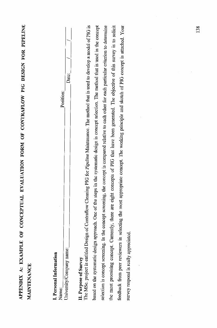
APPE
ND
IXA:
EXAM
PLE
OFC
ON
CEP
TUAL
EVAL
UAT
ION
FORM
OFC
ON
TRAF
LOW
PIG
DES
IGN
FOR
PIPE
LIN
EM
AIN
TE
NA
NC
E
I.P
erso
na
lIn
form
ati
on
Name
:Po
sition
:U
nive
rsity
/Com
pany
nam
e:^
^/
7
II.
Pur
pose
ofS
urve
y
TheM
Sc.p
rojec
tisen
titled
Desig
nofC
ontra
flow
Clea
ningP
IGfor
Pipe
lineM
ainten
ance
.The
metho
dtha
tisu
sedt
odev
elopa
mode
lofP
IGis
based
onthe
syste
matic
desig
napp
roach
.One
ofthe
steps
inthe
syste
matic
desig
nisc
once
ptsel
ectio
n.Th
emeth
odtha
tisus
edin
theco
ncep
tse
lectio
nis
conc
epts
creen
ing.I
nthe
conc
epts
creen
ing,t
heco
ncep
tisc
ompa
redrel
ative
toea
choth
erfor
each
parti
cular
criter
ionto
deter
mine
themo
stpro
misin
gco
ncep
t.Cu
rrentl
y,the
reare
eight
conc
epts
ofPI
Gtha
thav
ebe
enge
nerat
ed.T
heob
jectiv
eof
this
surve
yis
toso
licit
feedb
ack
from
peer
review
ersin
selec
ting
themo
stap
prop
riate
conc
ept.
The
worki
ngpr
incipl
ean
dsk
etch
ofPI
Gco
ncep
tisa
ttach
ed.Y
our
surv
eyre
spon
dis
real
lyap
prec
iate
d.
13
8
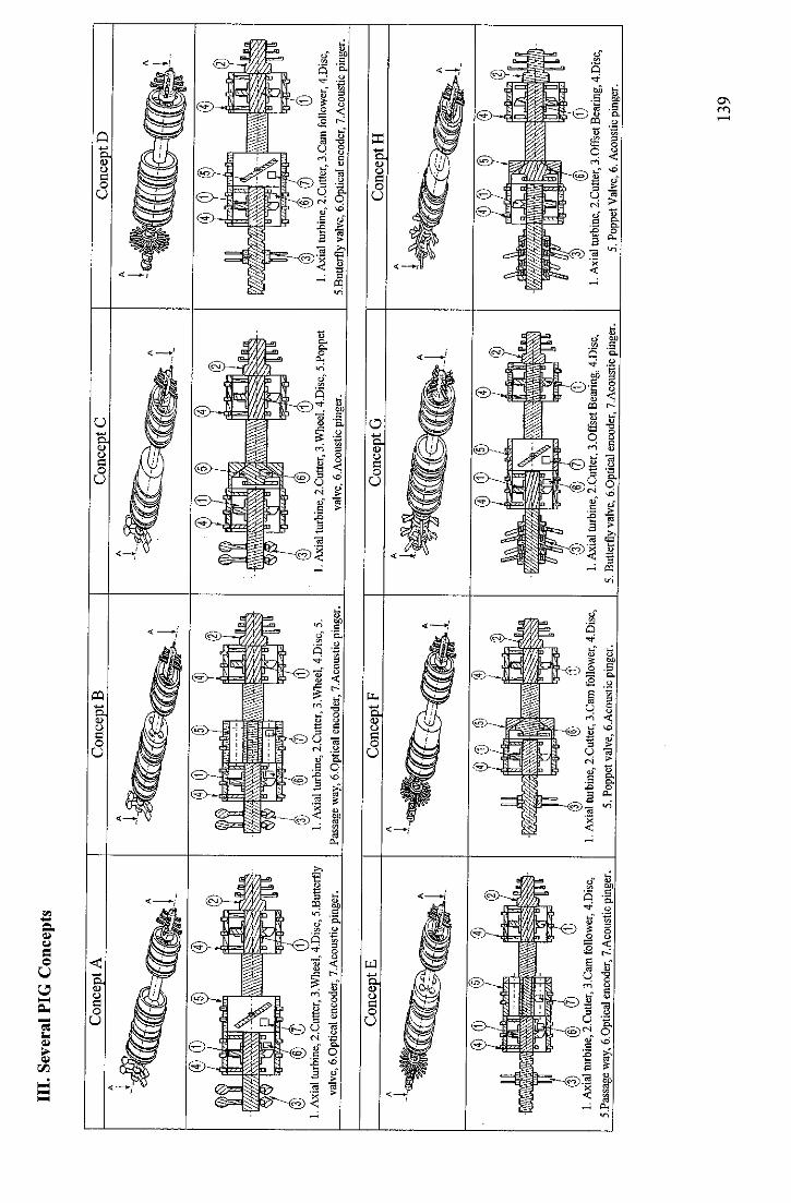
III.
Seve
ral
PIG
Con
cept
s
Con
cept
A
@®
®(1
1.A
xial
turb
ine,
2.C
utte
r,3.
Whe
el,4
.Dis
c,5.
But
terf
lyva
lve,
6-0p
tical
enco
der,
7.A
cous
ticpi
nger
.
Con
cept
E
(3)(6)
<f)(1)
1.A
xial
turb
ine,
2.C
utte
r,3.
Cam
follo
wer
,4.D
isc,
5.Pa
ssag
ew
ay,6
.0pt
ical
enco
der,
7.A
cous
ticpi
nger
.
Con
cept
B
©<S/
(Z)G)
1.A
xial
turb
ine,
2.C
utte
r,3.
Whe
el,4
.Dis
c,5.
Pass
age
way
,6.0
ptic
alen
code
r,7.
Aco
ustic
ping
er.
Con
cept
F
•1
^
@©
3)1.
Axi
altu
rbin
e,2.
Cut
ter,
3.C
amfo
llow
er,4
.Dis
c,
5.Po
ppet
valv
e,6.
Aco
ustic
ping
er.
Con
cept
C
(3)(§)
(t)1.
Axi
altu
rbin
e,2.
Cut
ter,
3.W
heel
,4.D
isc,
5.Po
ppet
valv
e,6.
Aco
ustic
ping
er.
Con
cept
G
I.A
xial
turb
ine,
2.C
utte
r,3.
0ffs
etB
earin
g,4.
Dis
c,5.
But
terf
lyva
lve,
6.0p
tical
enco
der,
7.A
cous
ticpi
nger
.
Con
cept
D
®©
®&
I.A
xial
turb
ine,
2.C
utte
r,3.
Cam
follo
wer
,4.D
isc,
5.B
utte
rfly
valv
e,6.
0ptic
alen
code
r,7.
Aco
ustic
ping
er.
®©
01.
Axi
altu
rbin
e,2.
Cut
ter,
3.O
ffse
tBea
ring,
4.D
isc,
5.Po
ppet
Val
ve,6
.Aco
ustic
ping
er.
Con
cept
H
13
9
IV.
Wo
rkin
gP
rinc
iple
Co
nce
pt
AFl
uid
ener
gyis
conv
erte
din
toro
tatio
nal
ener
gyby
usin
gan
axia
ltur
bine
.In
fron
tof
the
PIG
,acu
tterw
hich
has
afu
nctio
nto
rem
ove
solid
depo
sit
isat
tach
ed.
Itis
driv
enby
the
axia
ltur
bine
.T
om
ove
ina
coun
ter
flow
dire
ctio
n,a
driv
em
echa
nism
ofof
fset
whe
elis
atta
ched
atth
ebe
hind
the
PIG
.Iti
sdriv
enby
anot
hert
urbi
new
here
the
fluid
flow
thro
ugh
this
turb
ine
isre
gula
ted
bya
butte
rfly
valv
e.Th
eof
fset
whe
elax
isis
notp
erpe
ndic
ular
toth
eax
isof
the
pipe
line.
Whe
ndr
iven
byth
etu
rbin
e,a
rota
tiona
lto
rque
isap
plie
dto
adr
ive
mec
hani
smsh
aft,
the
whe
elm
ove
forw
ard
mak
ing
asp
iralm
otio
nlik
ea
scre
ww
hich
rota
tes
and
mov
esal
ong
agr
oove
.To
dete
rmin
ean
obstr
uctio
nof
flow
chan
ged,
anop
tical
enco
deri
suse
dto
mea
sure
the
rota
tiona
lspe
edof
the
shaf
ttur
bine
.Bas
edon
the
inpu
toft
his
optic
alen
code
r,th
ebu
tterfl
yw
illbe
driv
enby
anin
tern
alm
otor
whe
reth
epo
wer
sour
ceis
supp
lied
byan
inte
rnal
batte
ry.W
hen
the
fluid
flow
isin
capa
ble
tobe
conv
erte
din
toth
etra
ctio
nfo
rce
requ
ired
todr
ive
the
PIG
inth
eco
unte
rflo
wdi
rect
ion,
the
butte
rfly
valv
ew
illcl
ose.
The
PIG
will
actl
ike
aco
nven
tiona
lPI
Gw
here
the
fluid
flow
will
push
the
PIG
tore
turn
toth
ein
itial
poin
tofl
aunc
hing
.Iti
salso
equi
pped
with
anac
ousti
cpi
nger
devi
cew
hich
has
afu
nctio
nto
loca
teth
ePI
Gpo
sitio
nin
the
pipe
line.
Co
nce
pt
B
Att
hefr
onto
fthe
PIG
,acu
tter
whi
chha
safu
nctio
nto
rem
ove
solid
isat
tach
ed.I
tis
driv
enby
anax
ialt
urbi
new
hich
has
afu
nctio
nto
conv
ert
fluid
ener
gyin
toro
tatio
nal
ener
gy.
Adr
ive
mec
hani
smof
offs
etw
heel
whi
chha
sa
func
tion
topr
ovid
eth
etra
ctio
nfo
rce
tom
ove
ina
coun
ter
flow
dire
ctio
nis
atta
ched
atth
ebe
hind
ofth
ePI
G.I
tis
driv
enby
anot
her
turb
ine
whe
reth
eflu
idflo
wth
roug
hth
istu
rbin
eis
regu
late
dby
ase
vera
lpa
ssag
ew
aym
echa
nism
.Th
eof
fset
whe
elis
mou
nted
toa
driv
em
echa
nism
shaf
twith
sligh
tlyin
clin
edan
gle.
Whe
ndr
iven
byth
etu
rbin
e,a
rota
tiona
ltor
que
isap
plie
dto
the
driv
em
echa
nism
shaf
t.Th
ew
heel
rota
tes
and
mov
esin
circ
umfe
rent
iald
irect
ion
and
simul
tane
ously
mov
esin
the
axia
ldire
ctio
nbe
caus
eof
incl
ined
angl
eof
whe
el.I
nth
ese
vera
lpas
sage
way
mec
hani
sm,t
here
isa
plat
eth
atca
nco
ntro
lthe
flow
thro
ugh
pass
age
way
.Iti
sdr
iven
byan
inte
rnal
mot
orw
here
the
pow
erso
urce
issu
pplie
dby
anin
tern
alba
ttery
.In
case
ther
eis
anob
struc
tion
offlu
idflo
wch
angi
ng,b
ased
onth
em
easu
rem
entr
otat
iona
lspe
edof
axia
ltur
bine
shaf
tby
anop
tical
enco
der,
the
plat
ew
illpa
rtial
lyop
enor
clos
eto
regu
late
the
fluid
flow
thro
ugh
the
turb
ine.
Inca
seth
eflu
idflo
wis
inca
pabl
eto
beco
nver
ted
into
the
tract
ion
forc
ere
quire
dto
driv
eth
ePI
Gin
the
coun
terf
low
dire
ctio
n,th
epl
ate
inth
ese
vera
lpas
sage
way
mec
hani
sms
will
clos
eth
epa
thof
fluid
.As
aco
nseq
uenc
e,th
ePI
Gw
illbe
push
edby
the
fluid
flow
tore
turn
toth
ein
itial
poin
tofl
aunc
hing
.To
loca
teth
epo
sitio
nof
the
PIG
durin
gth
eop
erati
on,t
hePI
Gis
equi
pped
with
anac
oust
icpi
nger
devi
ce.
14
0
Co
nce
pt
CTh
ere
are
two
axia
ltur
bine
sin
the
conc
eptw
hich
has
afu
nctio
nto
conv
erth
ydra
ulic
ener
gyin
totra
nsla
tiona
len
ergy
.A
tthe
fron
tof
the
PIG
,th
etu
rbin
eis
used
todr
ive
acu
tter
whi
chha
sa
func
tion
tore
mov
eso
lidde
posi
t.A
tthe
behi
ndof
the
PIG
,th
etu
rbin
eis
used
todr
ive
adr
ive
mec
hani
smof
offs
etw
heel
.The
offs
etw
heel
axis
isno
tper
pend
icul
arto
the
axis
ofth
epi
pelin
e.W
hen
driv
enby
the
turb
ine,
aro
tatio
nalt
orqu
eis
appl
ied
toth
edr
ive
mec
hani
smsh
aft.
The
whe
elro
tate
san
dm
oves
inci
rcum
fere
ntia
land
sim
ulta
neou
sly
mov
esin
axia
ldire
ctio
nbe
caus
eof
incl
ined
angl
eof
whe
el.
This
turb
ine
iseq
uipp
edw
itha
popp
etva
lve
whi
chha
sa
func
tion
tore
gula
teth
eflu
idflo
wth
roug
hth
etu
rbin
e.It
ispe
rpet
ual
mec
hani
sms
whe
reth
eflu
idflo
wth
roug
hth
isva
lve
depe
nds
onsti
ffnes
sof
the
sprin
g.W
hen
the
fluid
flow
isin
capa
ble
tobe
conv
erte
din
toth
etra
ctio
nfo
rce
requ
ired
todr
ive
the
PIG
inth
eco
unte
rflo
wdi
rect
ion,
the
popp
etva
lve
will
clos
e.A
sa
cons
eque
nce
the
fluid
keep
flow
ing,
the
PIG
will
bepu
shed
byth
eflu
idflo
wto
retu
rnto
the
initi
alpo
into
flau
nchi
ng.
Itis
also
equi
pped
with
anac
ousti
cpi
nger
devi
cew
hich
hasf
unct
ion
tolo
cate
the
PIG
posi
tion
inth
epi
pelin
e.
Co
nce
pt
DFl
uid
ener
gyis
conv
erte
din
toro
tatio
nal
ener
gyby
usin
gan
axia
ltur
bine
.In
fron
tof
the
PIG
,acu
tterw
hich
has
afu
nctio
nto
rem
ove
solid
depo
siti
sat
tach
ed.I
tis
driv
enby
the
axia
ltur
bine
.To
mov
ein
aco
unte
rfl
owdi
rect
ion,
adr
ive
mec
hani
smof
cam
follo
wer
isat
tach
edat
the
behi
ndof
the
PIG
.It
isdr
iven
byan
othe
rtu
rbin
ew
here
the
fluid
flow
thro
ugh
this
turb
ine
isre
gula
ted
bya
butte
rfly
valv
e.Th
edr
ive
mec
hani
smof
cam
follo
wer
cons
ists
oftra
vers
ere
vers
esc
rew
whi
cha
nutm
ount
edw
ithbr
istle
sca
ntra
vela
long
this
scre
w.W
hen
driv
enby
the
turb
ine,
aro
tatio
nalt
orqu
eis
appl
ied
toth
edr
ive
mec
hani
smsh
aft.
This
rota
tiona
ltor
que
isco
nver
ted
into
the
trans
latio
nalp
ropu
lsion
forc
efo
rth
ePI
Gm
ovem
enta
ndre
cipr
ocat
ing
mov
emen
tof
nuti
nth
etra
vers
ere
vers
esc
rew
.In
itial
ly,t
henu
ttra
vel
mov
esfo
rwar
dun
tilit
reac
hes
the
end
ofth
etra
vers
ere
vers
esh
aft.
Due
toth
eun
ique
char
acte
ristic
ofth
ebr
istle
whi
chis
easi
erto
mov
efo
rwar
dra
ther
than
back
war
d,th
ePI
Gw
illm
ove
forw
ard
until
the
nut
reac
hes
atth
een
dof
the
trave
rse
reve
rse
shaf
tin
the
oppo
site
dire
ctio
n.Th
isse
quen
tial
step
ofth
edr
ive
mec
hani
smis
repe
ated
cont
inuo
usly
tom
ake
the
PIG
able
tocr
awl
info
rwar
ddi
rect
ion.
Tode
term
ine
anob
struc
tion
offlo
wch
angi
ng,
anop
tical
enco
der
isus
edto
mea
sure
the
rota
tiona
lsp
eed
ofth
etu
rbin
esh
aft.
Bas
edon
the
inpu
toft
his
optic
alen
code
r,th
ebu
tterfl
yw
illbe
actu
ated
byan
inte
rnal
mot
orw
here
the
pow
erso
urce
issu
pplie
dby
anin
tern
alba
ttery
.In
case
the
fluid
flow
isin
capa
ble
tobe
conv
erte
din
toth
etra
ctio
nfo
rce
requ
ired
todr
ive
the
PIG
inth
eco
unte
rflo
wdi
rect
ion,
the
butte
rfly
valv
ew
illcl
ose
ihs
path
offlu
id.
The
PIG
will
actl
ike
aco
nven
tiona
lPIG
whe
reth
eflu
idflo
ww
illpu
shth
ePI
Gto
retu
rnto
the
initi
alpo
into
flau
nchi
ng.I
tis
also
equi
pped
with
anac
ousti
cpi
nger
devi
cew
hich
hasf
unct
ion
tolo
cate
the
PIG
posi
tion
inth
epi
pelin
e.
Co
nce
ptE
Att
hefro
ntof
the
PIG
,acu
tter
whi
chha
sa
func
tion
tore
mov
eso
lidis
atta
ched
.Iti
sdr
iven
byan
axia
ltur
bine
whi
chha
sfu
nctio
nto
conv
ert
fluid
ener
gyin
toro
tatio
nale
nerg
y.A
driv
em
echa
nism
ofca
mfo
llow
erw
hich
has
afu
nctio
nto
prov
ide
the
tract
ion
forc
eto
mov
ein
coun
ter
flow
dire
ctio
nis
atta
ched
atth
ebe
hind
ofth
ePI
G.I
tis
driv
enby
anot
hert
urbi
new
here
the
fluid
flow
thro
ugh
this
turb
ine
isre
gula
ted
bya
14
1
seve
ralpa
ssag
ewa
ym
echa
nism
.The
drive
mec
hani
smof
cam
follo
werc
onsis
tsof
trave
rsere
verse
screw
which
anut
mou
nted
with
thebr
istle
can
scro
llalo
ngth
issc
rew.A
rotat
iona
ltor
que
drive
nby
theax
ialtu
rbin
eis
appl
iedto
the
trave
rsere
verse
screw
.The
nutm
ounte
dwi
ththe
brist
leis
force
dto
move
forwa
rdun
tilrea
ched
theen
dof
thetra
verse
revers
escre
wwh
ilethe
PIG
issti
llin
idlep
ositio
n.As
thenu
trea
ched
atthe
end
ofthe
trave
rserev
erse
screw
,itw
illm
ove
conti
nuou
slyin
aba
ckwa
rddir
ectio
n.As
aco
nseq
uenc
ethe
trave
rserev
erse
screw
still
rotat
ing,t
hebr
istle
onthe
nutw
illgri
pthe
pipeli
nean
dthe
PIG
will
move
inaf
orward
direc
tion.
This
sequ
entia
lstep
ofthe
drive
mech
anism
isrep
eated
conti
nuou
slyto
make
thePIG
able
tocra
wlin
theco
unter
flow
direct
ion.I
nthe
severa
lpass
agew
ayme
chan
ism,t
here
isap
latet
hat
canc
ontro
lthef
lowthr
ough
thepa
ssage
way.
Itis
drive
nbya
ninte
rnalm
otorw
here
thepo
wers
ource
issu
pplie
dbya
ninte
rnalb
attery
Incas
ethe
reis
anob
struc
tiono
fflow
chan
ging,
based
onthe
measu
remen
trota
tiona
lspe
edof
axial
turbin
esha
ftby
anop
tical
enco
dert
hepla
tewi
llpa
rtiall
yop
enor
close
toreg
ulate
theflu
idflo
wthr
ough
thetur
bine.
Whe
nthe
fluid
flow
isinc
apab
leto
beco
nvert
edint
oth
e'tra
ction
force
requir
edto
drive
thePI
Gin
theco
unter
flow
direc
tion,
thepla
tein
thesev
eralp
assag
ewa
yme
chan
ismsw
illblo
ckthe
path
offlu
idAs
aco
nseq
uenc
ethe
fluid
keep
flowi
ng,t
hePI
Gwi
llbe
push
edby
theflu
idflo
wto
return
tothe
initia
lpoin
tofla
unch
ing.T
oloc
atethe
posit
ionof
the
PIG
durin
gth
eop
erat
ion,
the
PIG
iseq
uipp
edw
ithan
acou
stic
ping
erde
vice
.
Co
nce
pt
F
There
aretw
oax
ialtur
bines
inthe
conc
eptw
hich
hasa
functi
onto
conv
erthy
drauli
cene
rgyint
otra
nslat
ional
energ
y.At
thefro
ntof
thePI
Gthe
turbin
eisu
sed
todr
iveac
utter
which
hasa
func
tion
torem
ove
solid
depo
sit.A
tthe
behin
dof
thePI
G,the
turbin
eis
used
todr
ivead
rive
mech
anism
ofca
mfol
lower.
This
turbin
eise
quipp
edwi
thap
oppe
tvalv
ewhic
hhas
afun
ction
toreg
ulate
theflu
idflo
wthr
ough
thetur
bine
Itis
ape
rpetu
alm
echa
nism
where
theflu
idflo
wth
roug
hth
isva
lvede
pend
son
stiffn
ess
ofthe
sprin
g.Th
edr
ivem
echa
nism
ofca
mfo
llowe
rco
nsists
ofat
ravers
erev
erses
crew
which
anut
moun
tedwi
thbri
stlec
antra
vela
longt
hisscr
ew.W
hend
riven
bythe
turbin
e,ar
otatio
nalto
rque
isap
plied
tothe
drive
mec
hanis
msh
aft.T
hisro
tation
altor
que
isco
nvert
edint
otra
nslat
ional
prop
ulsion
force
forthe
PIG
mov
emen
tand
recip
roca
ting
mov
emen
tofth
enu
talo
ngth
ere
verse
trave
rsesc
rew.
Initi
ally,
the
nutt
rave
lmov
esfo
rwar
dun
tilit
reac
hest
heen
dof
the
trave
rserev
erse
shaft
.Due
tothe
uniqu
ech
arac
terist
icof
thebr
istle
which
isea
siert
om
ove
inaf
orwa
rddir
ectio
nrat
hert
han
inab
ackw
arddir
ectio
nthe
PIGwi
llmov
eforw
ardun
tilthe
nutr
each
esat
theen
dofth
etrav
erser
evers
esha
ftin
theop
posit
edire
ction
.This
seque
ntial
stepo
fthed
rive
mec
hanis
mis
repea
tedco
ntinu
ously
toma
kethe
PIG
able
tocra
wlin
thefo
rward
direc
tion.
Ifthe
fluid
flow
can
notb
eco
nvert
edint
othe
tracti
onfor
cereq
uired
todri
vethe
PIGin
theco
unter
flow
direc
tion,
thepo
ppet
valve
willc
lose.
With
theflu
idflo
wsti
llkeep
flowi
ngthe
PIGwi
llbe
push
edby
thisf
luid
toret
urnto
theini
tialp
ointo
flaun
ching
.Ana
cous
ticpin
gerd
evice
isatt
ache
dtot
hePI
Gto
locate
thePI
Gpo
sition
inpi
pelin
edur
ing
oper
atio
n.
Con
cept
G
Fluid
energ
yis
conv
erted
into
rotat
ional
energ
yby
using
anax
ialtur
bine.
Infro
ntof
thePI
G,ac
utter
which
hasa
func
tion
torem
ove
solid
depo
sitis
attac
hed.
Itis
drive
nbyt
heax
ialtur
bine.
Tomo
vein
acou
nterf
lowdir
ectio
n,ad
rivem
echa
nism
ofoff
setbe
aring
isatt
ache
datth
e
14
2
behi
ndof
the
PIG.
Itis
driv
enby
anot
her
turb
ine
whe
reth
eflu
idflo
wth
roug
hth
istu
rbin
eis
regu
lated
bya
butte
rfly
valv
e.Th
edr
ive
mec
hani
smof
offs
etbe
arin
gco
nsist
sof
bear
ing
mou
nted
with
ase
tofl
eg.
Sinc
eth
ece
ntre
line
ofbe
arin
gis
offs
etfro
mth
ece
ntre
line
ofth
edr
ive
mec
hani
smsh
aft,
the
seto
fle
gcr
eate
anos
cilla
tem
otio
nof
outw
ard,
back
war
d,in
war
dan
dfo
rwar
das
the
shaf
tof
driv
em
echa
nism
rota
ting.
Whe
nth
eof
fset
bear
ing
mov
esfo
rwar
dfro
mth
ece
ntre
line
ofth
edr
ive
mec
hani
smsh
aft,
the
leg
cont
acts
the
pipe
line
and
crea
tes
tract
ion
forc
e.In
the
oppo
site
dire
ctio
n,w
hen
the
offs
etbe
arin
gm
oves
tow
ard
toth
ece
ntre
line
ofth
edr
ive
mec
hani
smsh
aft,
the
leg
does
not
cont
actw
ithth
epi
pelin
e.Le
gin
the
othe
rsid
eof
the
offs
etbe
arin
gfo
llow
sth
esa
me
cycl
eat
adi
ffere
ntph
ase.
This
sequ
entia
lste
pof
the
driv
em
echa
nism
isre
peat
edco
ntin
uous
lyto
mak
eth
ePI
Gab
leto
mov
ein
the
forw
ard
dire
ctio
nin
aw
alki
ngac
tion.
Tode
term
ine
anob
struc
tion
offlo
wch
ange
d,an
optic
alen
code
risu
sed
tom
easu
reth
ero
tatio
nals
peed
ofth
etu
rbin
e.Ba
sed
onth
ein
puto
fthi
sop
tical
enco
der,
the
butte
rfly
will
beac
tuate
dby
anin
tern
alm
otor
whe
reth
epo
wer
sour
ceis
supp
lied
byan
inter
nal
batte
ry.
Inca
seth
eflu
idflo
wis
inca
pabl
eto
beco
nver
ted
into
the
tract
ion
forc
ere
quire
dto
driv
eth
ePI
Gin
the
coun
terf
low
dire
ctio
n,th
ebu
tterfl
yva
lve
will
close
.Asa
cons
eque
nce,
the
PIG
will
bepu
shed
byth
eflu
idflo
wto
retu
rnto
the
initi
alpo
into
flau
nchi
ng.T
olo
cate
the
posit
ion
ofth
ePI
Gdu
ring
the
oper
atio
n,th
ePI
Gis
equi
pped
with
anac
oust
icpi
nger
devi
ce.
Co
nce
pt
H
Ther
ear
etw
oax
ialt
urbi
nes
inth
eco
ncep
twhi
chha
sa
func
tion
toco
nver
thyd
raul
icen
ergy
into
trans
latio
nale
nerg
y.A
tthe
front
ofth
ePI
G,
the
turb
ine
isus
edto
driv
ea
cutte
rw
hich
has
afu
nctio
nto
rem
ove
solid
depo
sit.
Att
hebe
hind
ofth
ePI
G,t
hetu
rbin
eis
used
todr
ive
adr
ive
mec
hani
smof
offs
etbe
arin
g.Th
istu
rbin
eis
equi
pped
with
apo
ppet
valv
ew
hich
has
afu
nctio
nto
regu
late
the
fluid
flow
thro
ugh
the
turb
ine.
Itis
ape
rpetu
alm
echa
nism
whe
reth
eflu
idflo
wth
roug
hth
isva
lve
depe
nds
onsti
ffnes
sof
the
sprin
g.Th
edr
ive
mec
hani
smof
offse
tbea
ring
cons
ists
ofbe
arin
gm
ount
edw
itha
seto
fleg
.Sin
ceth
ece
ntre
line
ofbe
arin
gis
offs
etfro
mth
ece
ntre
line
ofth
edr
ive
mec
hani
smsh
aft,
the
seto
fleg
crea
tean
oscil
late
mot
ion
ofou
twar
d,ba
ckwa
rd,i
nwar
dan
dfo
rwar
das
the
shaf
tofd
rive
mec
hani
smro
tatin
g.W
hen
the
offse
tbea
ring
mov
esfo
rwar
dfro
mth
ece
ntre
line
ofth
edr
ive
mec
hani
smsh
aft,
the
legco
ntac
tthe
pipe
line
and
crea
tea
tracti
onfo
rce.
Inth
eop
posit
edi
recti
on,w
hen
the
offse
tbea
ring
mov
esto
war
dto
the
cent
relin
eof
the
driv
em
echa
nism
shaf
t,th
eleg
does
notc
ontac
twith
the
pipe
line.
Leg
inth
eot
her
side
ofth
eof
fset
bear
ing
follo
ws
the
sam
ecy
cleat
adi
ffere
ntph
ase.
This
sequ
entia
lste
pof
the
driv
em
echa
nism
isre
peate
dco
ntin
uous
lyto
mak
eth
ePI
Gab
leto
mov
ein
the
forw
ard
dire
ctio
nin
aw
alki
ngac
tion.
Whe
nth
eflu
idflo
wis
inca
pabl
eto
beco
nver
ted
into
the
tracti
onfo
rce
requ
ired
todr
ive
the
PIG
inth
eco
unter
flow
dire
ction
,the
popp
etva
lve
will
close
.As
aco
nseq
uenc
eth
eflu
idke
epflo
win
g,th
ePI
Gw
illbe
push
edby
the
fluid
flow
tore
turn
toth
ein
itial
poin
tofl
aunc
hing
.Iti
salso
equi
pped
with
anac
ousti
cpi
nger
devi
cew
hich
hasa
func
tion
tolo
cate
the
PIG
posi
tion
inth
epi
pelin
e.
14
3
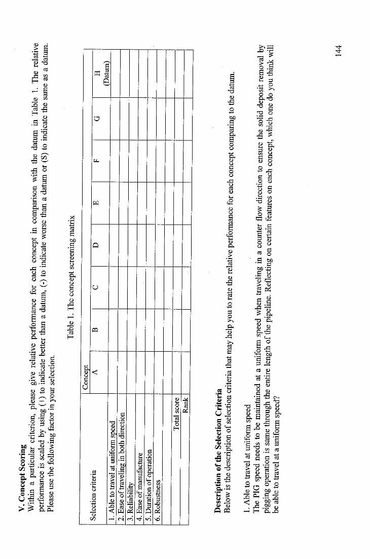
V.
Con
cept
Scor
ing
With
ina
parti
cular
crite
rion,
plea
segi
vere
lativ
epe
rform
ance
for
each
conc
ept
inco
mpa
rison
with
the
datu
min
Tabl
e1.
The
relat
ive
perfo
rman
ceis
scale
dby
usin
g(+
)to
indi
cate
bette
rtha
na
datum
,(-)
toin
dica
tewo
rsetha
na
datum
or(S
)to
indi
cate
thesa
me
asa
datum
.Pl
ease
use
the
follo
win
gfa
ctor
inyo
urse
lect
ion.
Tab
le1.
The
conc
epts
cree
ning
mat
rix
Sel
ecti
on
crit
eria
Con
cept
AB
CD
EF
GH
(Dat
um)
1.A
ble
totr
avel
atun
ifor
msp
eed
2.E
ase
oft
rave
ling
inbo
thdi
rect
ion
3.R
elia
bili
ty4.
Eas
eo
fm
anu
fact
ure
5.D
urat
ion
ofo
pera
tion
6.R
ob
ust
ness
To
tal
sco
re
Ran
k
Des
crip
tion
oft
he
Sele
ctio
nC
rite
ria
Below
isthe
desc
riptio
nof
selec
tionc
riteri
atha
tmay
help
yout
orat
ethe
relati
vepe
rform
ance
forea
chco
ncep
tcom
parin
gto
theda
tum.
1.A
ble
totr
avel
atun
iform
spee
dTh
ePIG
spee
dne
edst
obe
maint
ained
atau
niform
spee
dwh
entra
velin
gin
acou
nterf
lowdir
ectio
nto
ensu
rethe
solid
depo
sitrem
oval
bypig
ging
opera
tion
issa
methr
ough
theen
tirel
ength
ofthe
pipeli
ne.R
eflec
ting
once
rtain
featur
eson
each
conc
ept,
which
oned
oyo
uthin
kwi
llbe
able
totra
vela
taun
iform
spee
d?
14
4
2.E
ase
oft
rave
ling
inbo
thdi
rect
ions
The
PIG
need
sto
beab
leto
trav
elin
aco
unte
rflo
wdi
rect
ion
whi
ledo
ing
pigg
ing
and
tore
turn
toth
ein
itial
poin
tof
laun
chin
gw
hen
reac
hes
atth
een
do
fth
epi
pelin
eor
face
dan
obst
ruct
ion
like
valv
e,re
duci
ngdi
amet
eran
det
c.R
efle
ctin
gon
the
effe
cto
fth
efr
onta
lar
eaan
dsu
rfac
eco
ntac
twith
the
pipe
line
inne
rw
all,
whi
chco
ncep
tdo
you
thin
kw
illbe
ease
totr
avel
inbo
thdi
rect
ions
?
3.R
elia
bili
tyR
elia
bilit
yis
am
easu
rem
ento
fthe
capa
city
ofa
PIG
toop
erat
ew
ithou
tfai
lure
inth
eof
fsho
repi
pelin
eop
erat
ion
cond
ition
.Ref
lect
ing
once
rtai
nfe
atur
eson
each
conc
ept,
whi
chon
edo
you
thin
kw
illde
mon
stra
teth
efa
ilsa
fem
echa
nism
that
will
auto
mat
ical
lyre
turn
the
PIG
toth
ein
itial
poin
tofl
aunc
hing
?
4.
Ease
of
man
ufa
ctu
re
The
over
all
PIG
desi
gnis
asse
mbl
edfr
omth
ese
vera
lco
mpo
nent
s.R
efle
ctin
gin
the
com
plex
ityof
com
pone
nts
and
num
ber
ofco
mpo
nent
s,w
hich
conc
eptd
oyo
uth
ink
will
beea
sier
tom
anuf
actu
re?
5.D
urat
ion
ofo
pera
tion
The
PIG
isde
sign
edto
oper
ate
inth
eof
fsho
repi
pelin
es.
Ref
lect
ing
once
rtai
nfe
atur
eson
each
conc
ept,
whi
chon
edo
you
thin
kha
sa
leve
lco
nfid
ence
toco
mpl
ete
the
pigg
ing
proc
ess?
6.
Ro
bu
stn
ess
Rob
ustn
ess
isth
equ
ality
ofbe
ing
able
tow
ithst
and
with
the
vari
atio
nof
the
offs
hore
pipe
lineo
pera
ting
cond
ition
.Ref
lect
ing
once
rtai
nfe
atur
eson
each
conc
ept,
whi
chon
edo
you
thin
kw
illlo
ssfu
nctio
nally
whe
nth
ere
isva
riat
ion
inits
oper
atin
gco
nditi
on?
14
5
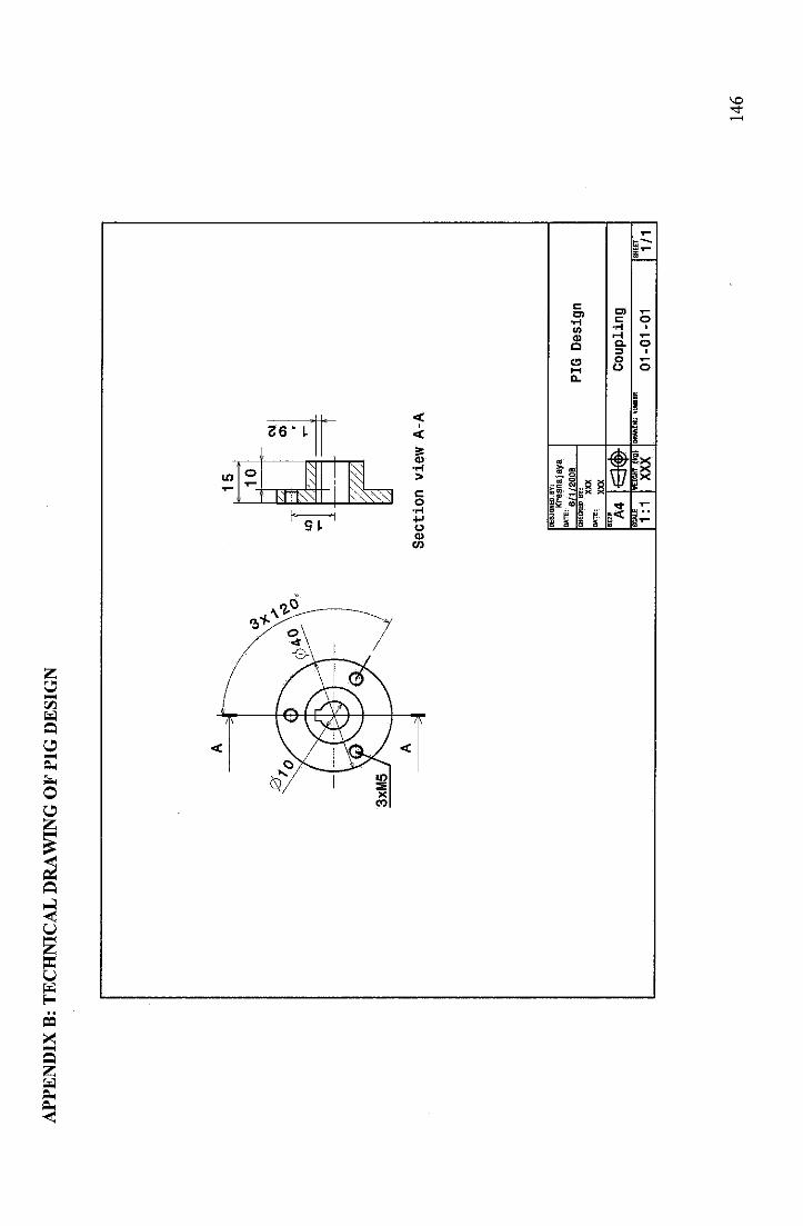
AP
PE
ND
IXB
:T
EC
HN
ICA
LD
RA
WIN
GO
FP
IGD
ES
IGN
Section
viewA-A
DE
SIG
NE
D.
BY
:
Kre
snaja
ya
6/1
/20
0B
CH
EC
KE
DB
Y:
XX
X
MTl
!XX
XS
IS A
4S
CA
LE
1:1
<3
#H
EIG
HT
(kg
)
XX
XD
RA
WIN
GN
UM
ER
PIG
Des
ign
Co
up
lin
g
01
-01
-01
SH
EE
T
1/1
14
6
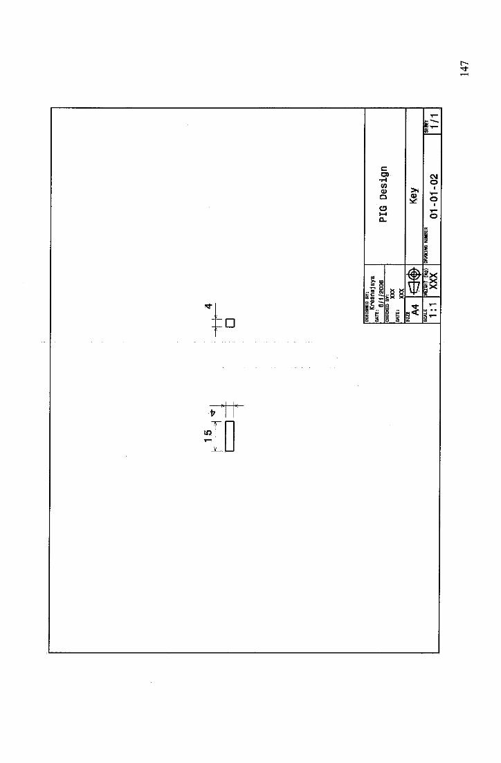
D
u>
co>
•HWCD
Q
oca ^T
s 1 _ £5 §
2
5
CMO
O
3ix
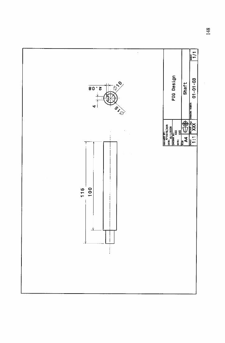
LO
90'S $$?/Vs
*
'%
oo
CO•HtnCD
a
-2, °
0) •
- £5 3
COx:CO
COo
5x
CO
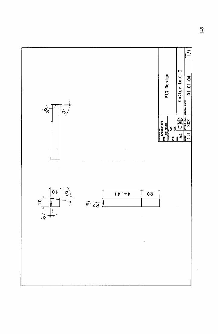
-I
o CM
BE
SIO
HE
DB
Y:
Kre
snaja
ya
DA
TE
:6
/1/2
00
6C
heck
ed
ar:
XX
X
WTE
:XX
XS
IZE A
4S
CA
LE
1:1
m$
WEI
GH
T(k
g)
XX
X
PIG
Desi
gn
Cu
tter
too
lI
DR
AW
ING
NU
MB
ER
01
-01
-04
1/1
14
9
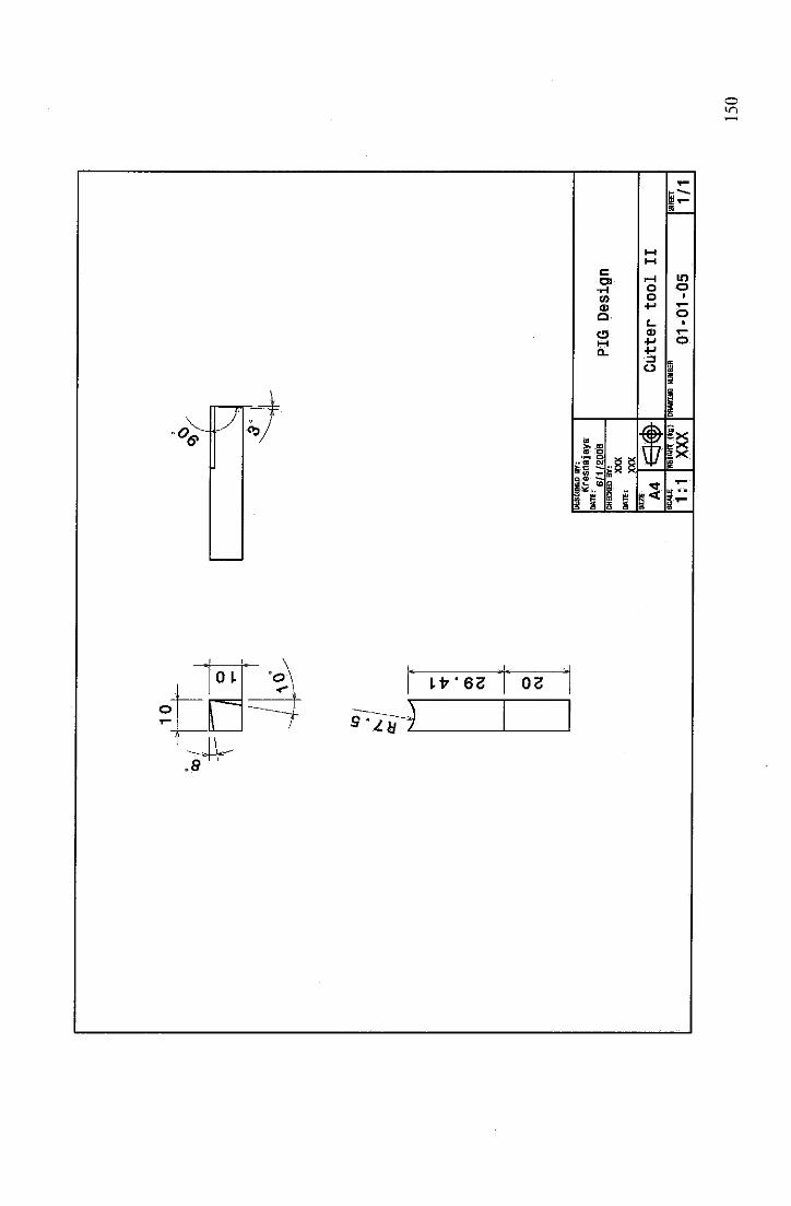
-1O
)C
M
O CM
DE
SIG
NE
DB
Y:
kre
snaj
aya
DA
TE
:6
/1/2
00
Bch
eck
ed
ar:
XX
X
MT*
:XX
XS
IZE A
4S
CA
LE
1:1
<3«
»W
EIG
HT
(kg
)
XX
X
PIG
Des
ign
Cu
tter
too
lII
DR
AW
ING
NU
MB
ER
01
-0
1-0
5S
HE
ET
1/1
15
0
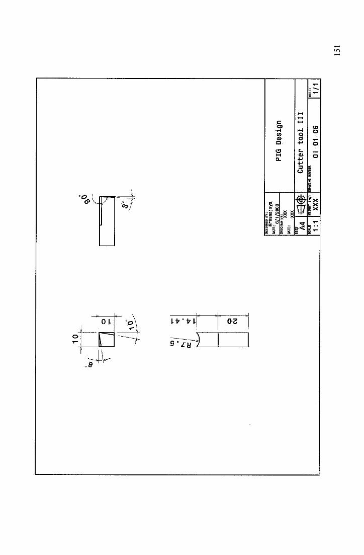
iO C
M
DE
SIG
NE
DB
Y:
Kre
sna
jaya
DA
TE
;6
/1/2
00
8C
HE
CK
ED
BY
:
XX
XD
AT
E:
XX
XS
IZE A
4S
CA
LE
1:1
*3
«»
HEI
GH
T(k
g)
XX
X
PIG
Des
ign
Cu
tter
too
lIII
EX
VW
INO
NW
fflE
R
01
-0
1-0
6S
HE
ET
1/1
15
1
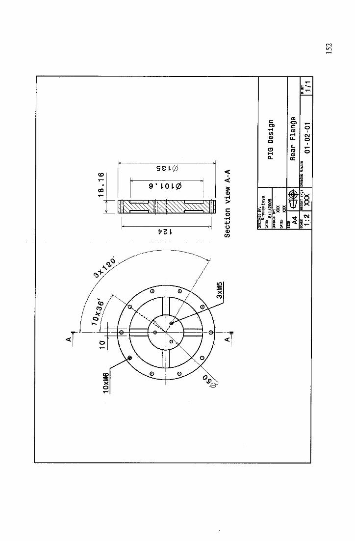
18.16
CM
•n
-*
CO
o •5
LO
CO
Section
viewA-A
DE
SIG
NE
DB
Y:
Kre
snaja
ya
Mlt:
6/1/
200B
CH
EC
KE
DB
Y:
XX
X
WTE
iXX
XS
IZE A
4m
*
PIG
Des
ign
Rea
rF
lan
ge
SC
AL
E
1:2
WEI
GH
T(k
g)
XX
XD
RA
WIN
GN
UM
BE
R
01
-02
-01
1/1
15
2
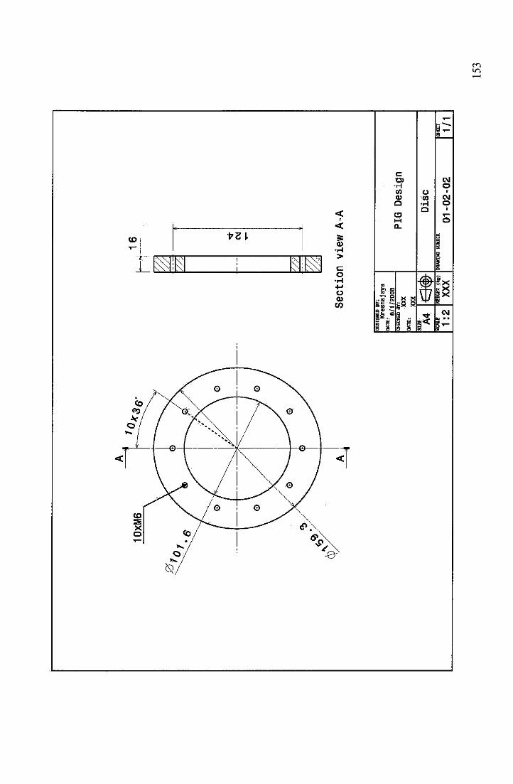
10
xM
6h
i1
6 CM
Secti
on
vie
wA
-A
DE
SIG
NE
DB
Y:
Kre
snaja
ya
DA
TE
:6
/1/2
0O
Bch
eck
ed
ar:
XX
X
0ATE
:XX
XS
IZE A
4S
CA
LE
1:2
m$
WEI
GH
T(k
g)
XX
X
PIG
Des
ign
Dis
cD
RA
WIN
GN
UM
BE
R
01
-0
2-0
2S
HE
ET
1/t
15
3
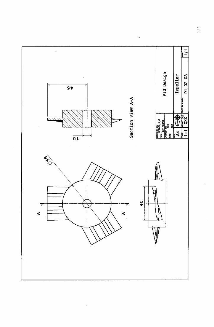
40
Section
viewA-A
DE
SIG
NE
DB
Y:
Kre
snaja
ya
DA
TE
:6
/1/2
00
6C
HE
CK
ED
BY
!
XX
X
•"*
XXX
SIZ
E A4
SC
AL
E
1:1
<3
#H
EIG
HT
(kg
)
XX
X
PIG
Desi
gn
Imp
ell
er
DR
AW
ING
NU
MB
ER
01
-02
-03
1/1
15
4
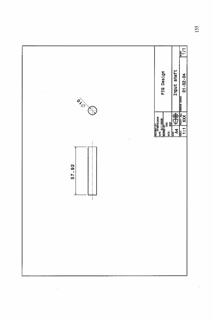
c
•HCOCD
a
o
a) o
5 s
+J
car- o
wCM
+-» O
=3 1
a.c o
&u
3
in
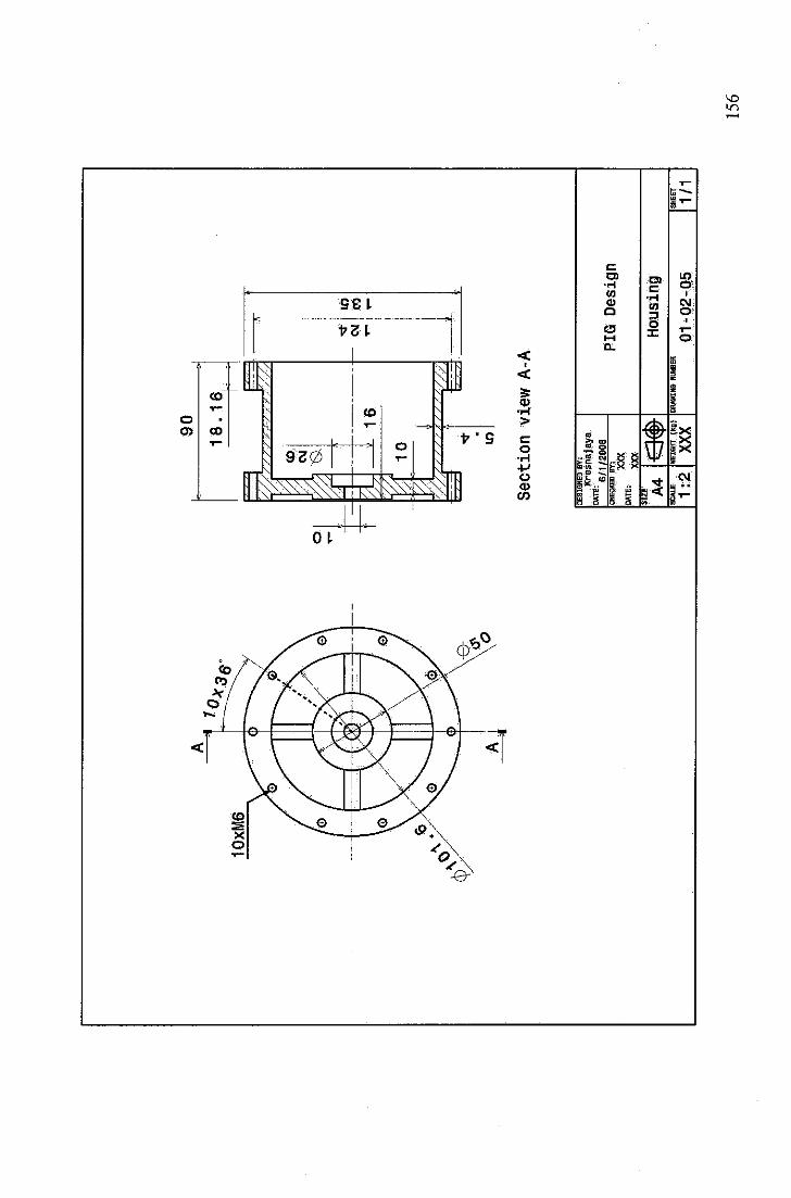
=q
90
18
.16
-r-^
f
tzzz
zzzz
zzZ
Zl
7 czz
CO
CM 10
16
—
10
ZZ
Z2
Section
viewA-A
DE
SIG
NE
DB
Y:
Kre
snaja
ya
°"*:
6/1/
2008
CM
LO
CO
CH
EC
KE
DB
Y:
XX
X
DATE
:XX
X
PIG
Desi
gn
SIZ
E A4
SC
AL
E
1:2
*m
WE
IGH
T(k
g)
XX
X
Ho
usi
ng
DR
AW
ING
NU
MB
ER
01
-02
-05
SH
EE
T
1/1
15
6
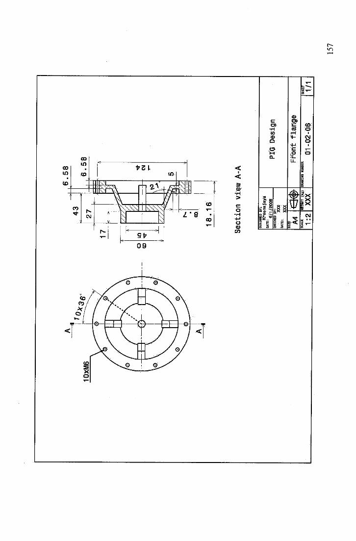
6.58
Section
viewA-A
DE
SIG
NE
DB
Y:
Kre
snaja
ya
DA
TE
:6
/1/g
Bch
eck
ed
sr:
XX
X
w™
XXX
SIZ
E A4
1:2
m$
HEI
GH
T(k
g)
XX
X
PIG
Des
ign
Front
flange
DR
AW
ING
NU
MB
ER
01
-02
-06
SH
EE
T
1/1
15
7

1 $*
53
86
l15
CM
DE
SIG
NE
DB
Y:
Kre
sna
jaya
DA
TE:
,6
/1/2
00
BC
HE
CK
ED
BY
:
XX
X
0Arai
XXX
SIZ
E A4
SC
AL
E
1:1
« WEI
GH
T(k
g)
XX
X
PIG
Des
ign
Outputshaft
DR
AW
ING
NU
MB
ER
01
-02
-07
SH
EE
T
1/1
15
8
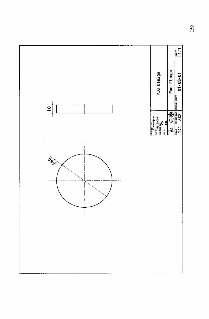
CDc raO) r~
•H mW r-l<D 4-
Q
T»O t=i—i UJa.
.f—1
as
Hi<u
ya a
- p5 S
«»u
3
COo
Exx
§xv
to
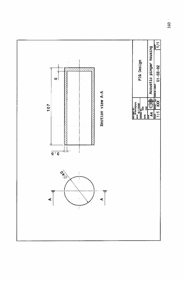
10
7L
O
CO
5
'///////////////////////////////////
•.
1
'<.//
////
///•
////
////
////
////
////
////
//)/
.,
Section
viewA-A
DE
SIG
NE
DB
Y:
Kre
snaja
ya
iu
tf-
6/1
/20
0B
ch
eck
ed
by
:
XX
X
wab
XXX
PIG
Des
ign
SIZ
E A4
m$
Acousticpingerhousing
1:1
HEI
GH
T(k
g)
XX
XD
RA
WIN
GN
UM
BE
R
01
-03
-02
SH
EE
T
1/1
16
0
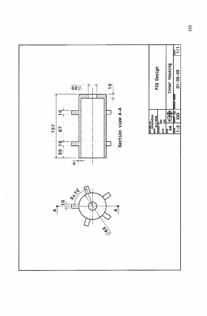
LO
157
30
10
67
j0
22
o CM
>//S
/,'/y//////
;•/
;/////////// V
i.
^»•
/////////S
////S
//////////)
L—-3
10
c.
Section
viewA-A
DE
SIG
NE
DB
Y:
Kre
snaj
aya
°ATE
:6/i/
200B
CH
EC
KE
DB
Y:
XX
X
WTE
:XX
XS
IZE A
4S
CA
LE
1:2
<m
WEI
GH
T(k
g)
XX
X
PIG
Des
ign
Innerhousing
DR
AW
ING
NU
MB
ER
01
-0
3-0
3S
HE
ET
1/1
16
1
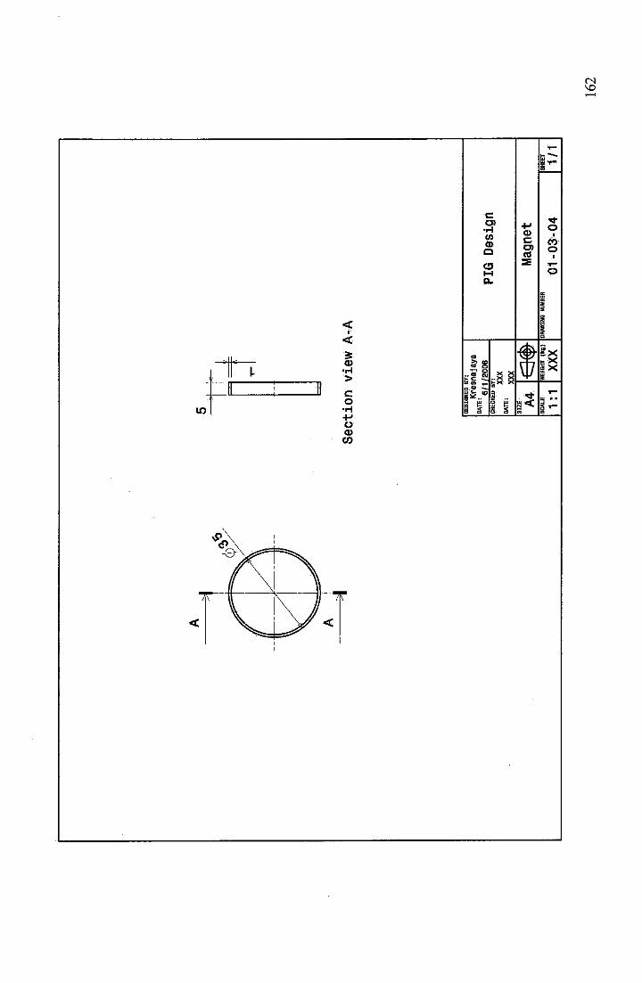
Section
viewA-A
DE
SIG
NE
DB
Y:
Kre
snaja
ya
DA
TE
:6
/1/g
QO
BC
HE
CK
ED
BY
!
XX
X
•"*
XXX
SIZ
E A4
SC
AL
E
1:1
<s«
»W
EIG
HT
(kg
)
XX
XD
RA
WIN
GN
UM
BE
R
PIG
Des
ign
Mag
net
01
-03
-04
SH
EE
T
1/1
16
2
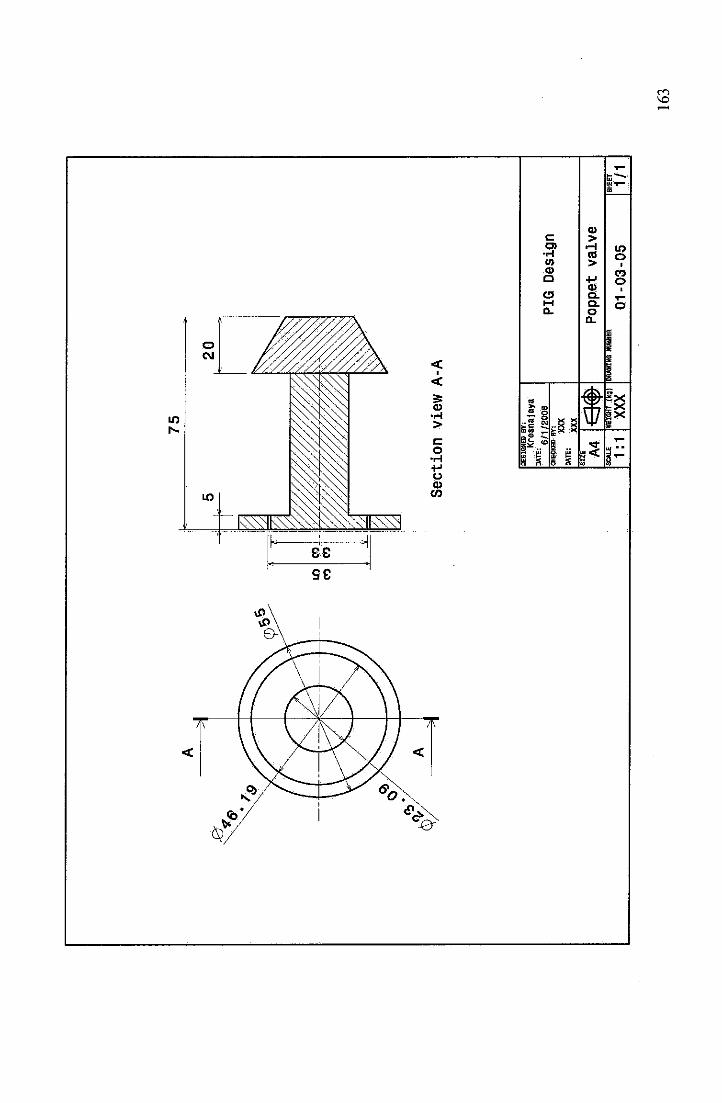
LO
CO
TT
y
75
Secti
on
vie
wA
-A
DE
SIG
NE
DB
Y:
Kre
snaja
ya
"^
6/1/
2008
PIG
Des
ign
CH
EC
KB
JB
Y!
XX
X
MTi
:XX
XS
IZE A
4r-
ir,
;\P
op
pet
valv
eU
jv;y
SC
AL
E
1:1
HEI
GH
T(k
g)
XX
XD
RA
WIN
GN
UM
BE
R.
01
-03
-05
SH
EE
T
1/1
16
3
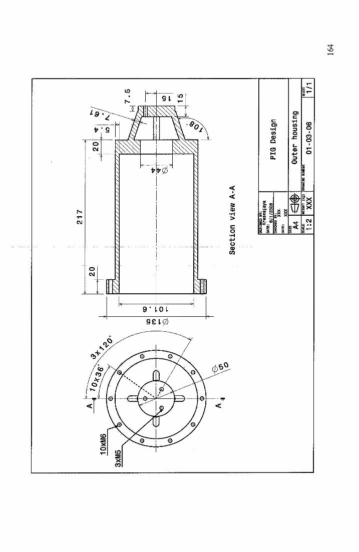
LO
CO
CO
21
7
20
L=
//V
/V
//1
/w
/V
/V
/V
///*
//,*
>//,/7
7
'//'/st's
//
/;
/sv
/;
//
/;
/;
/;
/<;/
///.
77
zzz
Section
viewA-A
DE
SIG
NE
DB
Y:
Kre
sna
jaya
DA
TE
:6
/1/2
00
BC
HE
CK
ED
BY
:
XX
X
•"n"
XXX
SIZ
E A4
SC
AL
E
1:2
m$
HEI
GH
T(k
g)
XX
X
PIG
Des
ign
Outerhousing
DR
AW
ING
NU
MB
ER
01
-03
-06
SH
EE
T
1/1
16
4
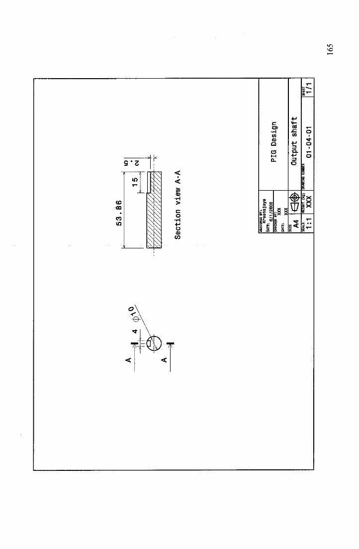
53
86
i•1
5r
Section
viewA-A
DE
SIG
NE
DB
Y:
Kre
snaj
aya
°ATE
:6/1
/200
8C
HE
CK
ED
BY
!
XX
XD
AT
E:
XX
XS
IZE A
4m
$
in
CM PI
GD
esig
n
Output
shaft
SC
AL
E
1:1
WEI
GH
T(K
C)
XX
XD
RA
WIN
GN
Uft
BE
R
01
-0
4-0
1S
HE
ET
1/1
16
5
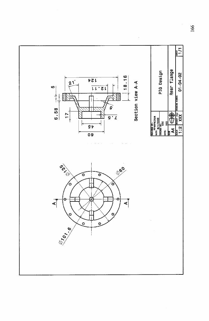
6.58
Section
viewA-A
DE
SIG
NE
DB
Y:
Kre
sna
jaya
DA
TE
:6
/1/g
QO
BC
HE
CK
ED
BY
!
XX
X
DATE
iXX
XS
IZE A
4
1:2
e3«»
HE
IGH
T(k
g)
XX
X
PIG
Desi
gn
Rea
rfl
an
ge
DR
AW
ING
NU
MB
ER
01
-04
-02
SH
EE
T
1/1
16
6
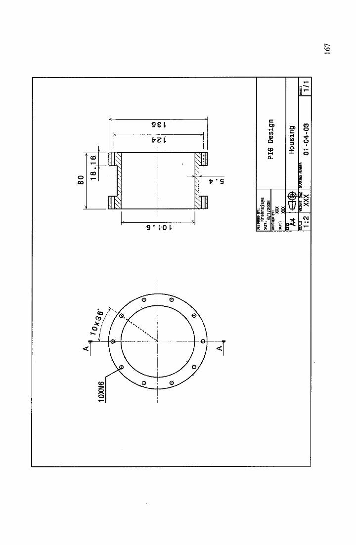
oCO
CD
CO
9SJ.
frcU
9' 10 I
V
V "9
•Hco
a
C5
men ^
IE*" 1 I i
C•HCO
O
*3
COo
o
o
gxXX
CM
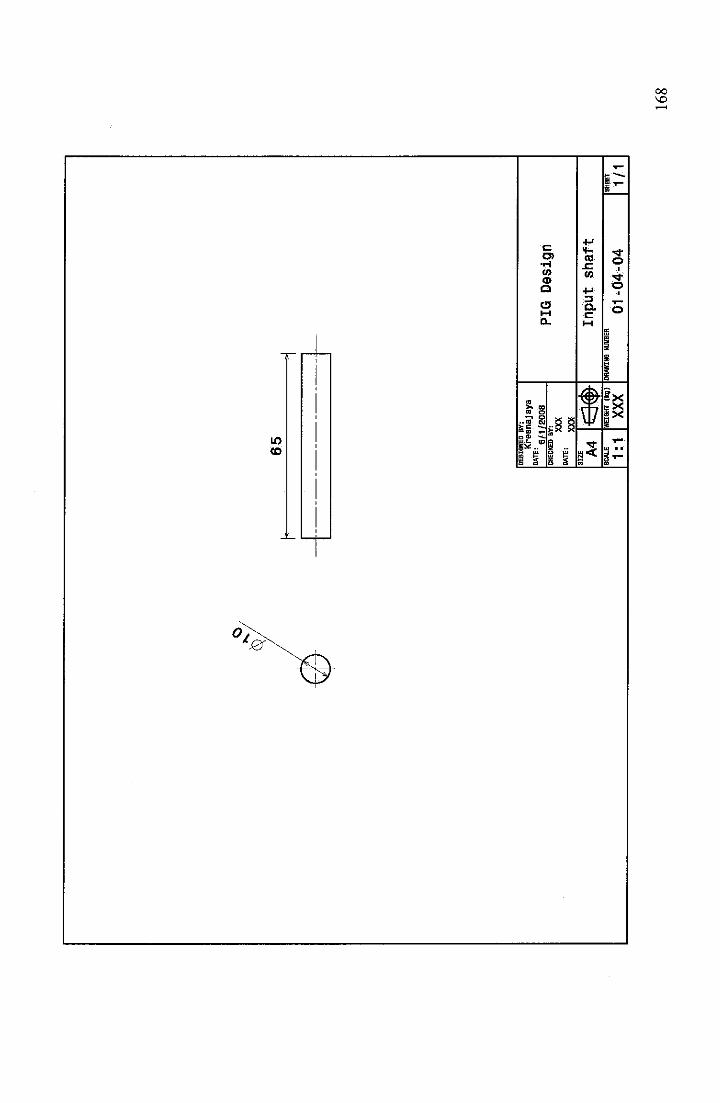
LOCO
fZ
o>•HCOCD
O
C5
_ £s I
4J
cd
CO
•3Q.
u
5
O•
o
Ex
CO
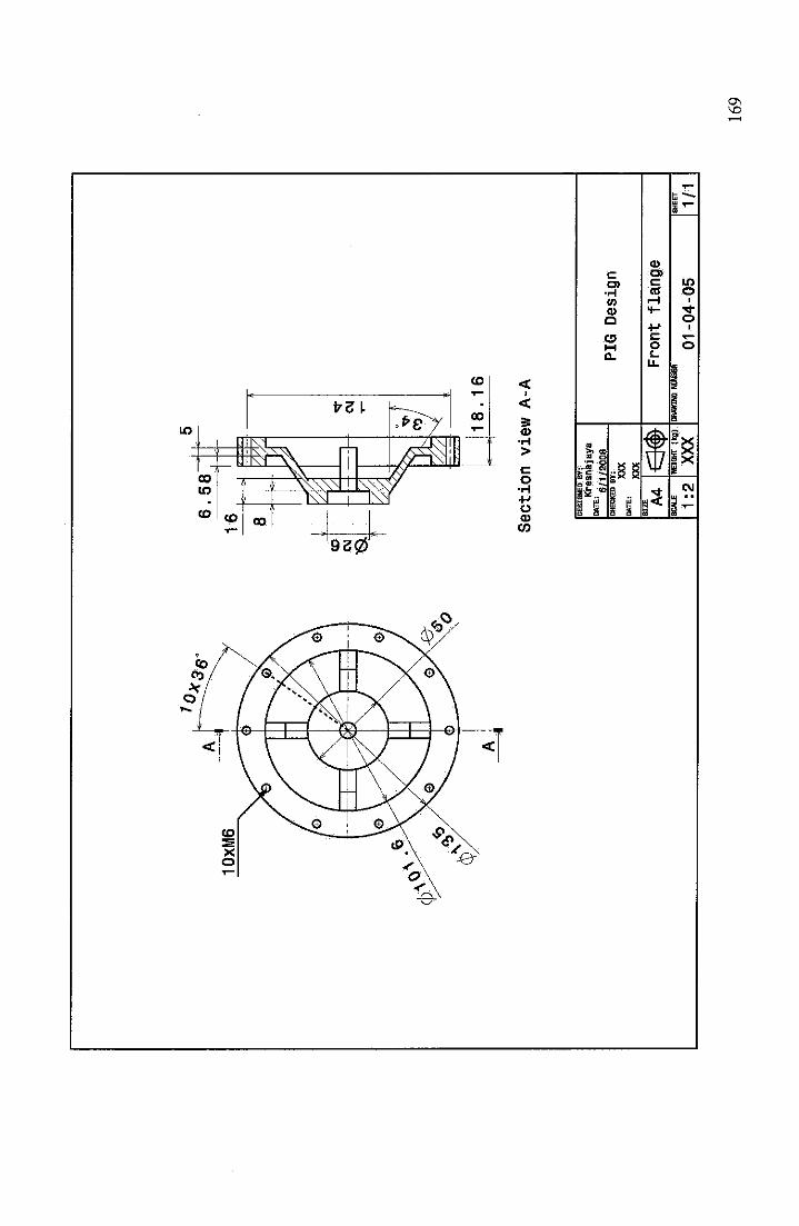
10
XM
6
6.5
8
Secti
on
vie
wA
-A
DE
SIG
NE
DB
Y:
Kre
snaj
aya
ME'
6/1/
2008
CH
EC
KE
DB
Y:
XX
XD
AT
E:
XX
XS
IZE A
4
1:2
<3«
»W
EIG
HT
(kg)
XX
X
PIG
Des
ign
Frontflange
DR
AW
ING
NU
MB
ER
01
-04
-05
SH
EE
T
1/1
16
9
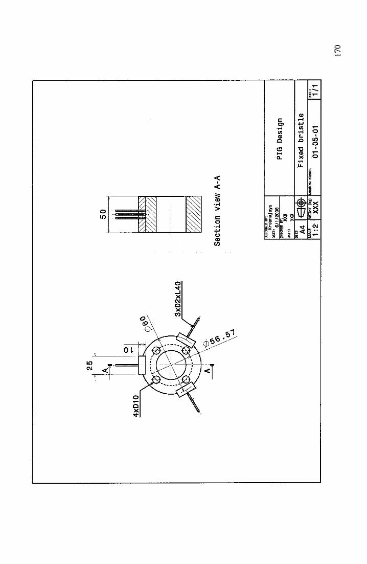
50
qfj
n
^tt
fsW
v//
////
,.
^^
Section
viewA-A
DE
SIG
NE
DB
Y:
Kre
snaja
ya
6/1
/20
06
DA
TE
:
CH
EC
KE
DB
Y!
XX
X
•**
XXX
SIZ
E A4
SC
AL
E
1:2
*m
WEI
GH
T(k
g)
XX
X
PIG
Desi
gn
Fixed
bristle
DR
AW
ING
NU
MB
ER
01
-05
-01
SH
EE
T
1/1
17
0
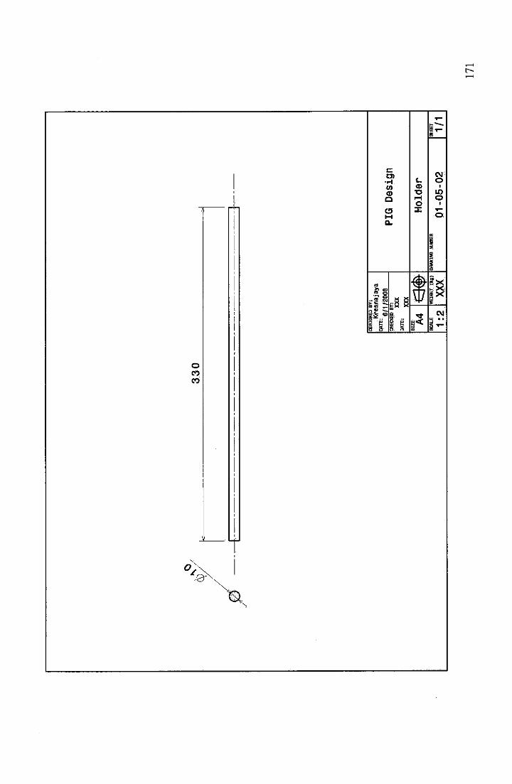
OCOCO
0,
•HCOCD
Q
o
mm _
1 i _ P5 S
wc o<D I
T3 LC)fH oO I
X ^
#u
2x
CM
c--
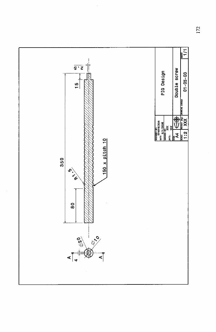
35
0
15
0x
pit
ch
10 D
ES
IGN
ED
BY
:
Kre
snaja
ya
DA
TE
:6
/1/2
00
8PI
GD
esig
nC
HE
CK
ED
BY
! XX
X
"**'
XXX
SIZ
E A4
nr,
^D
ou
ble
scre
wU
Jviy
SC
AL
E
1:2
HEI
GH
T(k
g)
XX
XD
RA
WIN
GN
UM
BE
R
01
-05
-03
SH
EE
T
1/1
17
2
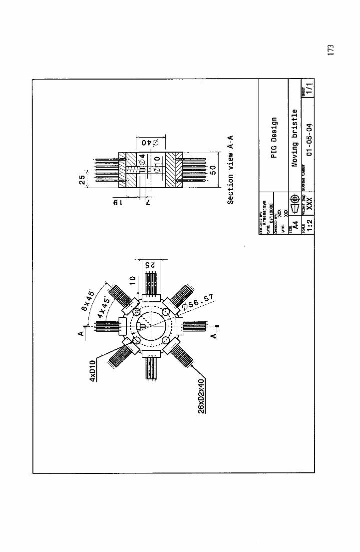
4XD10
Section
viewA-A
DE
SIG
NE
DB
Y:
Kre
sn
aja
ya
DA
TE
:6
/1/2
00
8C
HE
CK
ED
BY
!
XX
X
***•'
XXX
SIZ
E A4
SC
AL
E
1:2
m*
WE
IGH
T[k
g)
XX
X
PIG
Desi
gn
Movingbristle
DR
AW
ING
NU
MB
ER
01
-05
-04
SH
EE
T
1/1
17
3