hepa filters in safety applications · the "recovery" time for a cleanroom is the time...
TRANSCRIPT
HVAC Systems
Gordon Farquharson
July 2017

Slide 2 © PharmOut 2017
HVAC -A properly designed HVAC system can:
HVAC cannot clean up contaminated surfaces or protect
from poor operator practices
Heat Cool Humidify Dehumidify
Supply clean air
Dilute airborne
contaminants
Capture airborne particles
Create room differential pressures

Slide 3 © PharmOut 2017
Slide 4 © PharmOut 2017
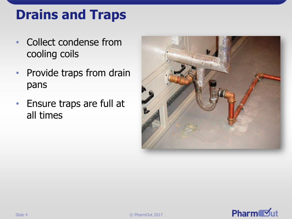
Drains and Traps
• Collect condense from cooling coils
• Provide traps from drain pans
• Ensure traps are full at all times

Slide 5 © PharmOut 2017
Systems Configuration – Single Plant
Central AHUParticles
Moisture
Cooling
Z
C
ZC = Zone control
Air volume & reheat
Z
C
Z
C
Z
C
Z
C
Z
C

Slide 6 © PharmOut 2017
Systems Configuration – Multiple Plant
Fresh Air AHUParticles
Moisture
Cooling
Heating
Pressurisation
Zonal AHUFine control Temp,
RH, Particles
Zonal AHUFine control Temp,
RH, Particles
Zonal AHUFine control Temp,
RH, Particles
ZC
ZC = Zone control
Air volume & reheat
ZC ZC ZC ZC ZC
Slide 7 © PharmOut 2017
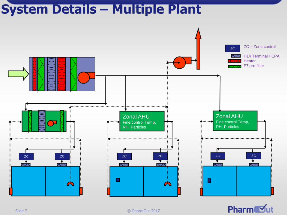
System Details – Multiple Plant
Zonal AHUFine control Temp,
RH, Particles
Zonal AHUFine control Temp,
RH, Particles
ZC
ZC = Zone control
H14 Terminal HEPA
Heater
F7 pre-filter
ZC ZC ZC ZC ZC
ZC

Slide 8 © PharmOut 2017
Sterile/Biologics Systems

Slide 9 © PharmOut 2017
How Many Air Changes are Enough?
In addition to meeting these requirements the following need to be considered when designing facility air supply:
Heat Gain
Exfiltration loss (pressurisation)
Particulate Gain
Recovery Time

Slide 10 © PharmOut 2017
What goes in must come out (we deal with rigid enclosures in HVAC)
Enclosure:RoomAir HandlerBarrier Isolator
Return Air to AHU
Supply air Exhaust air to outside
AIR IN = AIR OUT
Supply + Infiltration = Return + Exhaust + Exfiltration
Air Balance
Slide 11 © PharmOut 2017
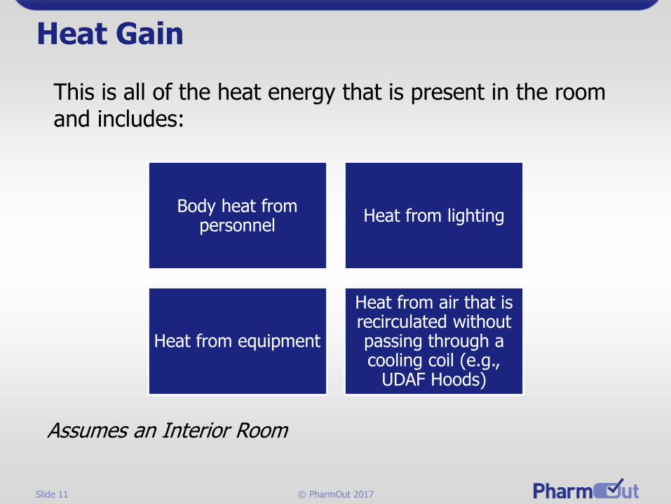
Heat Gain
This is all of the heat energy that is present in the room and includes:
Assumes an Interior Room
Body heat from personnel
Heat from lighting
Heat from equipment
Heat from air that is recirculated without passing through a cooling coil (e.g.,
UDAF Hoods)

Slide 12 © PharmOut 2017
Exfiltration Loss
This is the air that…
Escapes through cracks, passes under doors
Passes through mouse-holes
Passes into equipment

Slide 13 © PharmOut 2017
Estimation of Leakage
• Designer must estimate the leakage rate
• Designer must allow for any unknown leakage rates
• Doors should be the main leakage path
• Leakage rate through small gaps can be determined from:
▪ Q = 0.827 x A x (DP)0.5
Where
➢ Q = leakage rate m3/sec
➢ A = leakage area m2
➢ DP = differential pressure between spaces Pa

Slide 14 © PharmOut 2017
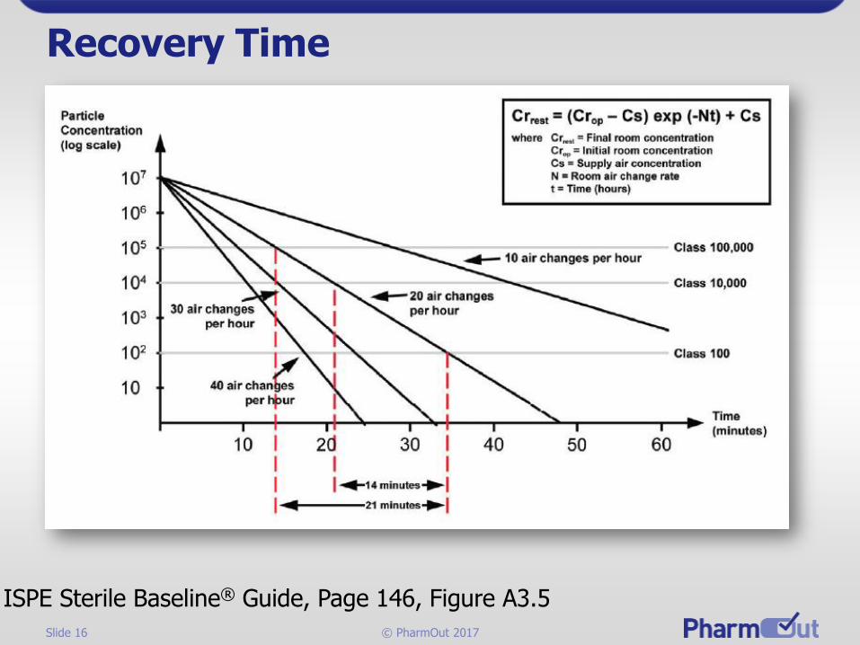
Recovery Time
The "recovery" time for a cleanroom is the time required for the particle count level to return to its "at rest" condition after production ceases and personnel leave the room. The “recovery” will follow an exponential curve, so it may take a long time to achieve its “at rest” condition.
Annex 1 Requirement
• The particulate conditions given… for the “at rest” state should be achieved after a short “clean up” period of 15-20 minutes (guidance value) in an unmanned state, after completion of operations.

Slide 15 © PharmOut 2017
Annex 1 Airborne Particle ClassificationRecovery time
Grade
Maximum permitted number of particles/m3 equal to or above:
In Operation At Rest
0.5 μm 5 μm N/A for UDF After
15 – 20 minute cleanup
0.5 μm 5 μm
A 3520 20 3520 20
B 352,000 2,900 3520 29
C 3,520,000 29,000 352,000 2900
D Not Defined
Not Defined
3,520,000 29,000
Slide 16 © PharmOut 2017
Recovery Time
ISPE Sterile Baseline® Guide, Page 146, Figure A3.5

Slide 17 © PharmOut 2017
Classic Cascading Pressure Airlock(as anticipated in our GMPs)
Less Clean Corridor
Clean Area
15 Pa
+
-
+30 Pa
+15 Pa
Conversion: 0.05 in H2O = 12.5 Pascals
Slide 18 © PharmOut 2017
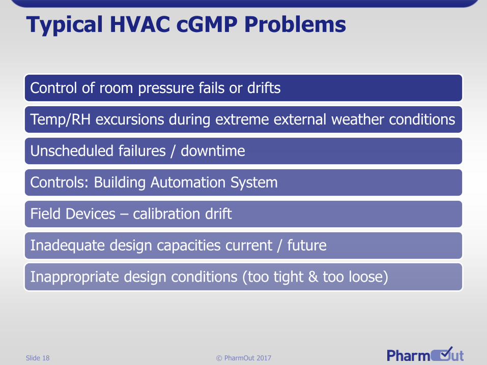
Typical HVAC cGMP Problems
Control of room pressure fails or drifts
Temp/RH excursions during extreme external weather conditions
Unscheduled failures / downtime
Controls: Building Automation System
Field Devices – calibration drift
Inadequate design capacities current / future
Inappropriate design conditions (too tight & too loose)
Slide 19 © PharmOut 2017
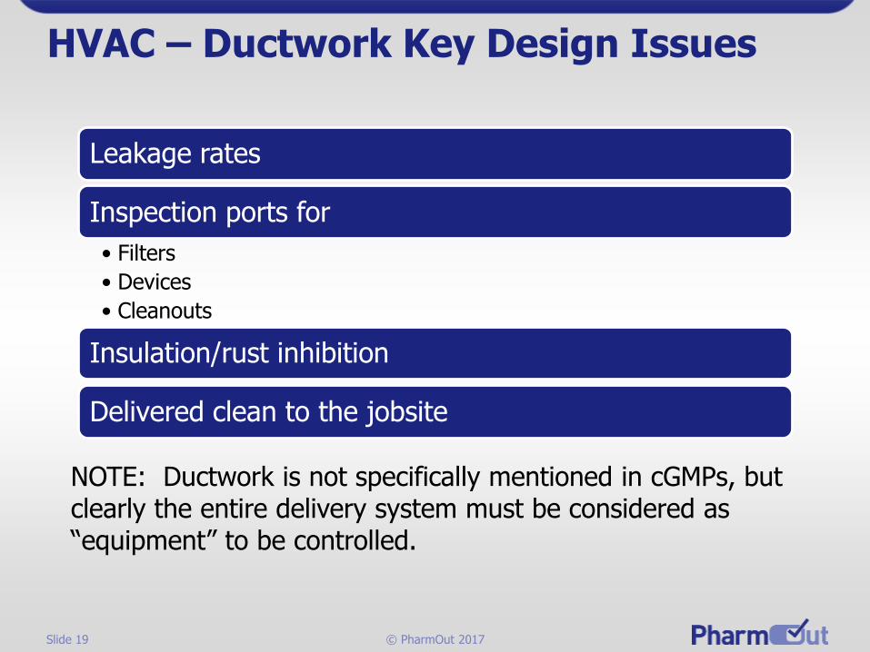
HVAC – Ductwork Key Design Issues
NOTE: Ductwork is not specifically mentioned in cGMPs, but clearly the entire delivery system must be considered as “equipment” to be controlled.
Leakage rates
Inspection ports for
• Filters
• Devices
• Cleanouts
Insulation/rust inhibition
Delivered clean to the jobsite

Slide 20 © PharmOut 2017
Thank you for your time.Questions?
Gordon Farquharson
www.pharmout.netExecutive Consultant