“helmholtz” capture solenoid mechanical structure calculations peter loveridge...
TRANSCRIPT

“Helmholtz” Capture SolenoidMechanical Structure Calculations
Peter Loveridge
STFC Rutherford Appleton Laboratory, UK
July 2008
Peter Loveridge, July 2008
Objectives
Using the magnetic forces calculated previously...
Evaluate the approximate dimensions of the magnet mechanical structure components in the cases where:
1. A fully open Helmholtz gap is required (compatible for a target wheel WITH spokes)
2. The Helmholtz gap is filled with structure material with the exception of a bridging structure across two short unsupported lengths (compatible with a SPOKELESS target wheel)
Is the required structure volume compatible with coil/target geometry?

Peter Loveridge, July 2008
Recap: Magnetic Forces
21
22
MEAN
21
22
21
22
MAX
1
MAX
1
121
:Stress Axial eCompressiv Average
:)R(@r Stress Hoop TensileMax
:)R(@r Stress Radial eCompressivMax
2
:Pressure Internal Equivalent
RR
F
RR
RRP
P
-ZZπR
FP
ZZ
R
R
P
R2
R1
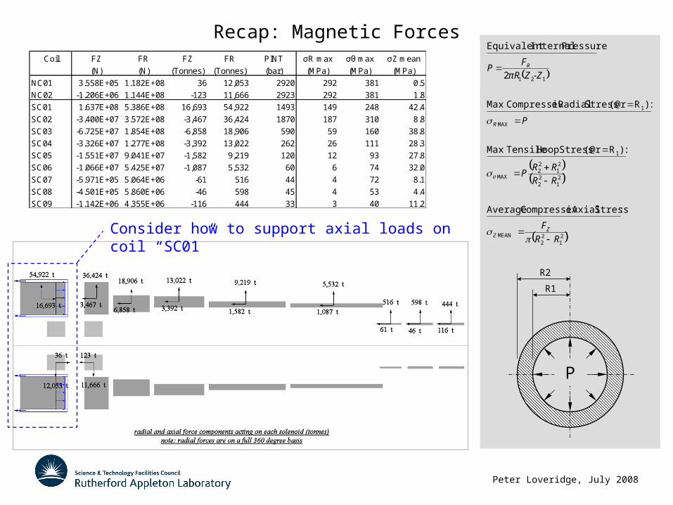
Coil FZ FR FZ FR PINT σR max σθ max σZ mean
(N) (N) (Tonnes) (Tonnes) (bar) (MPa) (MPa) (MPa)
NC01 3.558E+05 1.182E+08 36 12,053 2920 292 381 0.5
NC02 -1.206E+06 1.144E+08 -123 11,666 2923 292 381 1.8
SC01 1.637E+08 5.386E+08 16,693 54,922 1493 149 248 42.4
SC02 -3.400E+07 3.572E+08 -3,467 36,424 1870 187 310 8.8
SC03 -6.725E+07 1.854E+08 -6,858 18,906 590 59 160 38.8
SC04 -3.326E+07 1.277E+08 -3,392 13,022 262 26 111 28.3
SC05 -1.551E+07 9.041E+07 -1,582 9,219 120 12 93 27.8
SC06 -1.066E+07 5.425E+07 -1,087 5,532 60 6 74 32.0
SC07 -5.971E+05 5.064E+06 -61 516 44 4 72 8.1
SC08 -4.501E+05 5.860E+06 -46 598 45 4 53 4.4
SC09 -1.142E+06 4.355E+06 -116 444 33 3 40 11.2
Peter Loveridge, July 2008
Recap: Magnetic Forces
21
22
MEAN
21
22
21
22
MAX
1
MAX
1
121
:Stress Axial eCompressiv Average
:)R(@r Stress Hoop TensileMax
:)R(@r Stress Radial eCompressivMax
2
:Pressure Internal Equivalent
RR
F
RR
RRP
P
-ZZπR
FP
ZZ
R
R
P
R2
R1
Coil FZ FR FZ FR PINT σR max σθ max σZ mean
(N) (N) (Tonnes) (Tonnes) (bar) (MPa) (MPa) (MPa)
NC01 3.558E+05 1.182E+08 36 12,053 2920 292 381 0.5
NC02 -1.206E+06 1.144E+08 -123 11,666 2923 292 381 1.8
SC01 1.637E+08 5.386E+08 16,693 54,922 1493 149 248 42.4
SC02 -3.400E+07 3.572E+08 -3,467 36,424 1870 187 310 8.8
SC03 -6.725E+07 1.854E+08 -6,858 18,906 590 59 160 38.8
SC04 -3.326E+07 1.277E+08 -3,392 13,022 262 26 111 28.3
SC05 -1.551E+07 9.041E+07 -1,582 9,219 120 12 93 27.8
SC06 -1.066E+07 5.425E+07 -1,087 5,532 60 6 74 32.0
SC07 -5.971E+05 5.064E+06 -61 516 44 4 72 8.1
SC08 -4.501E+05 5.860E+06 -46 598 45 4 53 4.4
SC09 -1.142E+06 4.355E+06 -116 444 33 3 40 11.2
Consider how to support axial loads on coil “SC01”
Peter Loveridge, July 2008
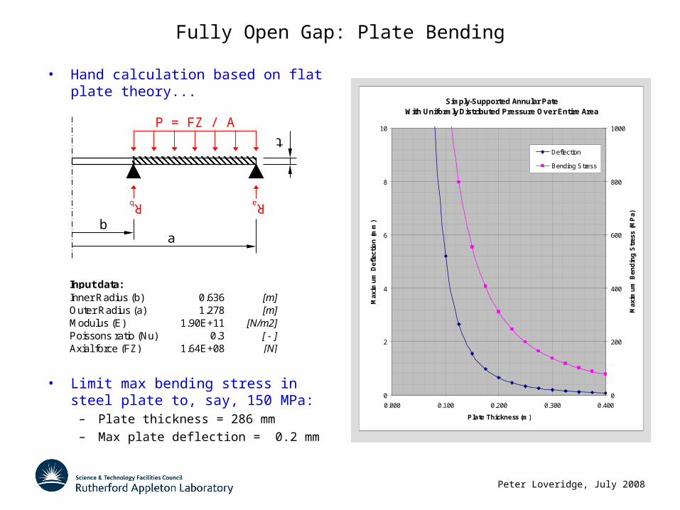
Fully Open Gap: Plate Bending
Simply-Supported Annular Pate With Uniformly Distributed Pressure Over Entire Area
0
2
4
6
8
10
0.000 0.100 0.200 0.300 0.400
Plate Thickness (m)
Max
imu
m D
efle
ctio
n (
mm
)
0
200
400
600
800
1000
Max
imu
m B
end
ing
Str
ess
(MP
a)
Deflection
Bending Stress
Input data:Inner Radius (b) 0.636 [m]Outer Radius (a) 1.278 [m]Modulus (E) 1.90E+11 [N/m2]Poissons ratio (Nu) 0.3 [ - ]Axial force (FZ) 1.64E+08 [N]
ba
t
P = FZ / A
Rb Ra
• Hand calculation based on flat plate theory...
• Limit max bending stress in steel plate to, say, 150 MPa:
– Plate thickness = 286 mm
– Max plate deflection = 0.2 mm

Peter Loveridge, July 2008
Fully Open Gap: Tensile Retaining Loads
P = FZ / A
Rb Ra
twotwi
L =
903
mm
• Envisage a retaining structure composed of two cylinders...
• From flat plate calculation we know:– Outer reaction (Ra) = 93.7 MN/360˚
– Inner reaction (Rb) = 70.0 MN/360˚
• Limit max tensile stress in steel retaining structure to, say, 150 MPa:
– two = 76 mm
– twi = 130 mm
– Elongationmm 0.7
E
LσΔL
Tensile Stress in Retaining Structure
0
100
200
300
400
500
600
700
0 50 100 150 200 250 300
Wall Thickness (mm)
Ten
sile
Str
ess
(MP
a)
Inner Cylinder
Outer Cylinder

Peter Loveridge, July 2008
Fully Open Gap: ANSYS Mechanical Simulation
180˚ Geometry Expansion
Axial Deflection Plot
0 mm 1.2 mm
Von-Mises Stress Plot
0 MPa 270 MPa
Axi-symmetic Mesh
76 mm thick outer cylinder
130 mm thick inner cylinder 286 mm thick end plate
Peter Loveridge, July 2008
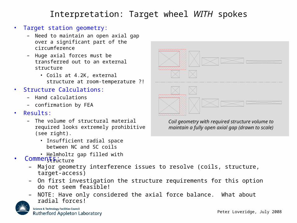
Interpretation: Target wheel WITH spokes
• Target station geometry:– Need to maintain an open axial gap over
a significant part of the circumference
– Huge axial forces must be transferred out to an external structure
• Coils at 4.2K, external structure at room-temperature ?!
• Structure Calculations:– Hand calculations
– confirmation by FEA
• Results:– The volume of structural material required
looks extremely prohibitive (see right).
• Insufficient radial space between NC and SC coils
• Helmholtz gap filled with structure
Coil geometry with required structure volume to maintain a fully open axial gap (drawn to scale)
• Comments:– Major geometry interference issues to resolve (coils, structure, target-access)– On first investigation the structure requirements for this option do not seem feasible!– NOTE: Have only considered the axial force balance. What about radial forces!
Peter Loveridge, July 2008
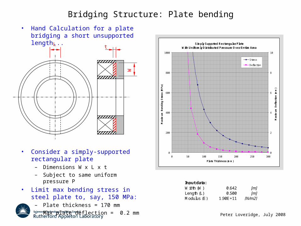
Bridging Structure: Plate bending
• Hand Calculation for a plate bridging a short unsupported length...
• Consider a simply-supported rectangular plate
– Dimensions W x L x t
– Subject to same uniform pressure P
• Limit max bending stress in steel plate to, say, 150 MPa:
– Plate thickness = 170 mm
– Max plate deflection = 0.2 mm
L
W
t
Input data:Width (W) 0.642 [m]Length (L) 0.500 [m]Modulus (E) 1.90E+11 [N/m2]
Simply Supprted Rectangular PlateWith Uniformly Distributed Pressure Over Entire Area
0
200
400
600
800
1000
0 50 100 150 200 250 300
Plate Thickness (mm)M
axim
um
Ben
din
g S
tres
s (M
Pa)
0
2
4
6
8
10
Max
imu
m D
efle
ctio
n (
mm
)
Stress
Deflection
Peter Loveridge, July 2008
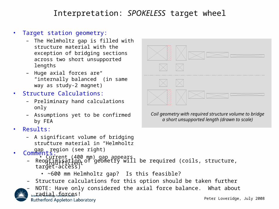
Interpretation: SPOKELESS target wheel
Coil geometry with required structure volume to bridge a short unsupported length (drawn to scale)
• Target station geometry:– The Helmholtz gap is filled with structure
material with the exception of bridging sections across two short unsupported lengths
– Huge axial forces are “internally balanced” (in same way as study-2 magnet)
• Structure Calculations:– Preliminary hand calculations only
– Assumptions yet to be confirmed by FEA
• Results:– A significant volume of bridging structure
material in “Helmholtz gap” region (see right)
• Current (400 mm) gap appears insufficient• Comments:
– Reoptimisation of geometry will be required (coils, structure, target-access)• ~600 mm Helmholtz gap? Is this feasible?
– Structure calculations for this option should be taken further– NOTE: Have only considered the axial force balance. What about radial forces!