helio helium-oxygen blender - precision medical · - 5 - helio 2 blender section 2: technical...
TRANSCRIPT

HELIO2
Helium-Oxygen BlenderService ManualService Manual
Model No. PM5400 Series (shown)
PM5500 Series
SAVE THESE INSTRUCTIONS
300 Held Drive Tel: (+001) 610-262-6090Northampton, PA 18067 USA Fax: (+001) 610-262-6080
www.precisionmedical.com

- 1 -HELIO2 Blender
CONTENTSSECTION 1: SAFETY INFORMATION - WARNINGS AND CAUTIONS ..............................2
EXPLANATION OF ABBREVIATION ........................................................ 3BLENDER DIAGRAMS ............................................................................. 3COMPONENT DESCRIPTIONS in Blender Diagrams ............................. 4
SECTION 2: TECHNICAL DESCRIPTION .................................................................... 5HELIOX / OXYGEN FLOW PATH INDICATION DIAGRAM ..................... 6
SECTION 3: MAINTENANCE PROCEDURES, REPAIR AND CALIBRATION ............. 7I. LOW FLOW (PM5400 Model) ............................................................... 7
Step 1: DISASSEMBLY ......................................................................... 7Step 2: CLEANING............................................................................... 10Step 3: LOW FLOW ASSEMBLY ......................................................... 10Step 4: TEST ........................................................................................ 13Typical Test Confi guration Diagram ...................................................... 13LOW Flow Operation Verifi cation Procedure........................................ 16
II. HIGH FLOW (PM5500 Model) ............................................................. 17Step 1: DISASSEMBLY ........................................................................ 17Step 2: CLEANING............................................................................... 20Step 3: HIGH FLOW ASSEMBLY ......................................................... 20Step 4: TEST ........................................................................................ 23Typical Test Confi guration Diagram ...................................................... 23HIGH Flow Operation Verifi cation Procedure ....................................... 26
III. INTERNATIONAL LOW / HIGH Flow Operation Verifi cation Procedure 27
SECTION 4: TROUBLESHOOTING ............................................................................. 28SECTION 5: BLENDER PARTS LIST ........................................................................... 29
Label information ...................................................................................... 30

- 2 -HELIO2 Blender
SECTION 1: SAFETY INFORMATION - WARNINGS AND CAUTIONS
WARNING Indicates a potentially hazardous situation which, if not avoided, could result in death or serious injury.
CAUTION Indicates a potentially hazardous situation which, if not avoided, may result in minor or moderate injury.
WARNING• Disconnect the HELIO2 Blender from all connections prior to disassembly.• Use Medical Heliox and Medical Oxygen when servicing to avoid contamination.• The HELIO2 Blender should be serviced by a qualifi ed service technician.• An Oxygen Analyzer/Monitor must be used to verify oxygen concentrations.• When reassembling the Blender, do not pressurize the system until the retaining
screw of the Proportioning Module has been fully tightened. The Proportioning Module can be forcefully ejected by gas pressure if not suffi ciently tightened.
• Always follow ANSI and CGA standards for Medical Gas Products, Flowmeters and Oxygen Handling.• When servicing requirements of Directive 93/42/EEC concerning medical
devices and all International Standards apply. (On CE marked devices ONLY)• DO NOT obstruct the alarm.• Oxygen Concentration Dial does not rotate 360 degrees. Rotating the dial
beyond the end point settings, will damage the Blender.
Service Warning• This Service Manual is provided for your safety and to prevent damage to the
HELIO2 Blender. • It is essential to read and understand this entire manual before attempting to service
the HELIO2 Blender.• If you have any questions regarding the installation, setup, operation, and/or
maintenance of the HELIO2 Blender, contact Precision Medical, Inc.
CAUTION• Use recommended lubricants sparingly as lubricant may migrate to other areas and
cause the Blender to malfunction.• When pressurizing the Blender inlets, avoid pressure surges greater than 100 psi (6.9 bar).• Be sure all connections are tight and leak free before returning to service.• Store Blender in a clean, dry area when not in use.• DO NOT steam autoclave.• DO NOT gas sterilize with (EtO) Ethylene Oxide.• DO NOT immerse HELIO2 Blender into any liquid.• DO NOT use if dirt or contaminants are present on or around the Blender or
connecting devices.• DO NOT clean with aromatic hydrocarbons.

- 3 -HELIO2 Blender
EXPLANATION OF ABBREVIATION
FIHe-O2Fractional Concentration of Inspired Helium-Oxygen
FIO2 Fractional Concentration of Inspired OxygenHeliox Helium-OxygenDISS Diameter Indexed Safety SystemNIST Non-Interchangeable Screw Threadlpm Liters Per Minutepsi Pounds Per Square Inchkpm Kilopond meter
BLENDER DIAGRAMS
DA
CB
FG
E
A
H
D
CB
GF
E
H
Note: PM5480 Model Shown

- 4 -HELIO2 Blender
ITEM COMPONENT DESCRIPTIONS in Blender Diagrams
APrimary Outlet Port A male DISS oxygen fi tting with check valve that delivers fl ow when engaged to any controlling device, such as a fl owmeter.
BOxygen Inlet FittingA female DISS or NIST oxygen fi tting with one way valve that is used to connect an oxygen supply hose.
CHeliox Inlet FittingA male DISS or NIST heliox fi tting with one way valve that is used to connect a heliox supply hose.
D
Oxygen Concentration DialA dial used for selecting oxygen concentrations between 20% -100% or 30% -100%. The FIO2 scale is used for reference only. The actual FIO2 must be verifi ed with an Oxygen Monitor.This Dial does not rotate 360°. The dial starts at 20% or 30% and ends at 100%.
E Rear Slide Mount with dove tail.
F
Auxiliary Bleed Collar The collar is used to engage and disengage the bleed. The bleed is necessary to maintain accurate FIO2 Concentration below 15 lpm for the High Flow and ≤ 3 lpm for the Low Flow. To activate the bleed, slide and rotate the knurled collar back until it contacts the cover. To deactivate the bleed, pull and rotate collar away from cover until bleed fl ow valve is closed.
G
Auxiliary Outlet Port A male DISS oxygen fi tting with check valve that delivers fl ow when engaged to any controlling device, such as a fl owmeter. This outlet is equipped with a bleed valve that allows the user to control if the bleed is ON or OFF. With the bleed in the ON position, this outlet delivers accurate oxygen concentrations in the following fl ows:
Model Flow RangeHigh Flow 2 – 100 lpmLow Flow 0 – 30 lpm
HAlarm An audible alarm that sounds due to an excessive pressure drop or deletion of either gas supply.

- 5 -HELIO2 Blender
SECTION 2: TECHNICAL DESCRIPTIONThe HELIO2 Blender is a medical device used to mix Medical Heliox and USP Oxygen into a gas source ranging from 20-100% or 30-100% oxygen. The inlet gas connections are standard DISS or NIST for each gas. The inlets are clearly marked and labeled on the bottom of the Blender. The outlets are standard DISS male oxygen connections.The front panel of the Blender has a dial that is used to set the specifi c FIO2 blend. The dial settings range from 20-100% on the PM5480 & PM5580 models and 30-100% on the PM5470 & PM5570 models.The Path of the GasesThe supply enters through the heliox and oxygen inlet connectors located on the bottom of the Blender. Each inlet connector contains a particulate fi lter and duckbill check valves which prevent possible reverse gas fl ow.Diaphragm Housing ModuleThe two gases then enter the two-stage pressure Diaphragm Housing Module. In this module, the pressures of both gas sources are equalized prior to entering the Proportioning Module. The pressure is equalized at the lower pressure. The diaphragm within the module responds to the difference in pressure and directs the movement of each check valve assembly contained within the heliox and oxygen chambers. The movement of each ball adjusts the amount of gas fl owing through the Diaphragm Housing Module, equalizing the heliox and oxygen pressures to the lower pressure.Proportioning ModuleFrom the Diaphragm Housing Module the gases fl ow into the Proportioning Module and are mixed according to the oxygen percentage selected on the Oxygen Concentration Dial. The Proportioning Module consists of a double ended valve positioned between two valve seats. One seat controls the passage of heliox and the other valve seat controls the passage of oxygen into the outlet. At this point, the two gases have been blended according to the oxygen percentage selected on the Oxygen Concentration Dial.The Oxygen Concentration Dial in the full counterclockwise position (20 / 30%), will completely close off the fl ow of oxygen, allowing only the Oxygen Concentration Dial in the full clockwise position (100%), will block the fl ow of heliox, permitting only the fl ow of oxygen through the Blender outlet.Alarm and Alarm BypassAn audible alarm located on the bottom of the Blender signals when the difference in pressure between the two inlet gases is ≥ 18 psi for Low Flow and ≥ 13 psi for High Flow. When the source gases are near equal pressure, the alarm bypass poppet will remain seated over the alarm channel and the alarm does not sound. When the gas pressures become unbalanced the higher pressure gas will unseat the poppet by overcoming the spring force causing gas to fl ow through the alarm channel and the alarm sounds. The oxygen concentration from the Blender will be that of the higher gas pressure. The Blender in the alarm/bypass mode will deliver the oxygen (100%) or heliox until the bypass mechanism resets when the source gas pressure is restored to a differential of approximately 6 psi (0.42 kg/cm2). If the Blender is set at 20 or 30% (depending on model), the OXYGEN source pressure is reduced or lost, the unit will not alarm because it will continue to deliver 20 or 30% concentration according to the setting. If the control is moved slightly from the 20 or 30% setting, the alarm will sound. Similarly, if the Blender is set to deliver 100% oxygen concentration and heliox source pressure is reduced or lost, the unit will not alarm because it will continue to deliver the selected 100% concentration. The alarm will not function when there is no fl ow to the blender.

- 6 -HELIO2 Blender
Gas OutletsThe Primary and Auxiliary Outlets are DISS male adapters with check valves.
HELIOX / OXYGEN FLOW PATH INDICATION DIAGRAM
Heliox(DISS shown)
DIAPHRAGMDIAPHRAGM
CHECK VALVE
DUCK BILL CHECK VALVEFILTER
PROPORTION-ING VALVE
ORIFICE
BYPASS CHECK VALVE
ALARM BYPASS VALVE
O2
(DISS shown)
AUDIBLE ALARM

- 7 -HELIO2 Blender
SECTION 3: MAINTENANCE PROCEDURES, REPAIR AND CALIBRATION
I. LOW FLOW (PM5400 Model) Step 1: DISASSEMBLY
Tools Required
#2 Phillips Screwdriver #3 Phillips Screwdriver 1/2 in. Open End WrenchSpanner Wrench (P/N 504839)
11/32 in. Nut Driver5/32 in. Long Hex KeySmall Retaining Ring pliers
Figure A1. Rotate dial [1] to the 12 o’clock position.2. Remove the two fl at head screws [2] on each
side of the top cover [3].3. Remove top cover by pulling upwards.
The cover will not come off unless the dial is at the 12 o’clock position.
[1]
[2]QUANTITY - 4
[3]
Figure B4. Use a ½ in. open end wrench to unscrew and
remove the heliox [4] and oxygen [5] inlet assemblies from bottom of the Blender. Oxygen inlet has left hand threads.
5. If manifold outlet assembly is present, unscrew the stem using a 5/32 hex key and holding the manifold outlet assembly to the bottom of the Blender.
6. Remove the four fl at head screws [2] from bottom cover [6].
7. Remove bottom cover.
[5]
[4]
[2]QUANTITY - 4
[6]
- 8 -HELIO2 Blender
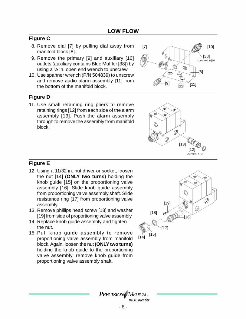
LOW FLOW Figure C8. Remove dial [7] by pulling dial away from
manifold block [8].9. Remove the primary [9] and auxiliary [10]
outlets (auxiliary contains Blue Muffl er [38]) by using a ½ in. open end wrench to unscrew.
10. Use spanner wrench (P/N 504839) to unscrew and remove audio alarm assembly [11] from the bottom of the manifold block.
[8]
[10]
[11][9]
[7]
[38]contained in [10]
Figure D11. Use small retaining ring pliers to remove
retaining rings [12] from each side of the alarm assembly [13]. Push the alarm assembly through to remove the assembly from manifold block.
[12]QUANTITY - 2
[13]
Figure E12. Using a 11/32 in. nut driver or socket, loosen
the nut [14] (ONLY two turns) holding the knob guide [15] on the proportioning valve assembly [16]. Slide knob guide assembly from proportioning valve assembly shaft. Slide resistance ring [17] from proportioning valve assembly.
13. Remove phillips head screw [18] and washer [19] from side of proportioning valve assembly.
14. Replace knob guide assembly and tighten the nut.
15. Pull knob guide assembly to remove proportioning valve assembly from manifold block. Again, loosen the nut (ONLY two turns) holding the knob guide to the proportioning valve assembly, remove knob guide from proportioning valve assembly shaft.
[14][15]
[16][18]
[19]
[17]
- 9 -HELIO2 Blender
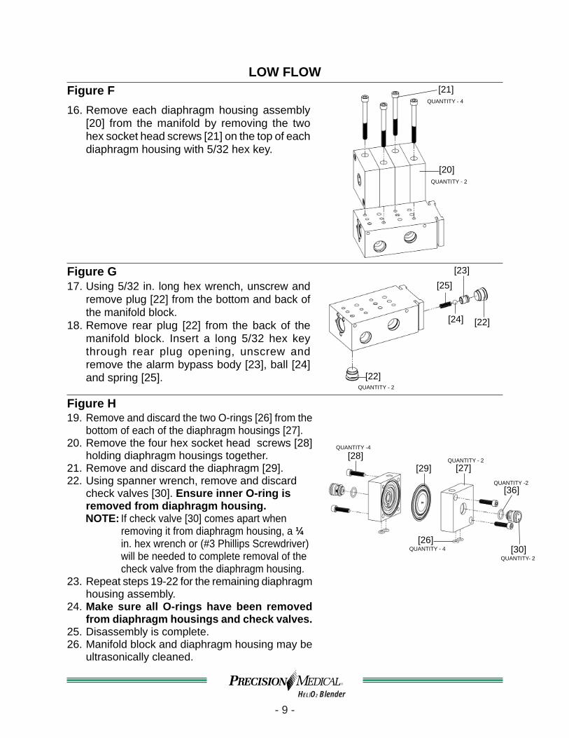
LOW FLOW Figure F16. Remove each diaphragm housing assembly
[20] from the manifold by removing the two hex socket head screws [21] on the top of each diaphragm housing with 5/32 hex key.
[20]QUANTITY - 2
[21]QUANTITY - 4
Figure G17. Using 5/32 in. long hex wrench, unscrew and
remove plug [22] from the bottom and back of the manifold block.
18. Remove rear plug [22] from the back of the manifold block. Insert a long 5/32 hex key through rear plug opening, unscrew and remove the alarm bypass body [23], ball [24] and spring [25].
QUANTITY - 2
[23][25]
[24] [22]
[22]
Figure H19. Remove and discard the two O-rings [26] from the
bottom of each of the diaphragm housings [27].20. Remove the four hex socket head screws [28]
holding diaphragm housings together.21. Remove and discard the diaphragm [29].22. Using spanner wrench, remove and discard
check valves [30]. Ensure inner O-ring is removed from diaphragm housing.NOTE: If check valve [30] comes apart when
removing it from diaphragm housing, a ¼ in. hex wrench or (#3 Phillips Screwdriver) will be needed to complete removal of the check valve from the diaphragm housing.
23. Repeat steps 19-22 for the remaining diaphragm housing assembly.
24. Make sure all O-rings have been removed from diaphragm housings and check valves.
25. Disassembly is complete.26. Manifold block and diaphragm housing may be
ultrasonically cleaned.
[27]
[26]
QUANTITY - 2
QUANTITY - 4
[28]QUANTITY -4
[29]
[30]QUANTITY- 2
[36]QUANTITY -2
- 10 -HELIO2 Blender
Step 2: CLEANINGPrecision Medical, Inc. recommends using an ultrasonic cleaner for cleaning all non-elastometric and non-metallic components. However, cleaning with an all-purpose liquid cleaner and rinsing with clean, warm water may be substituted. Both methods require thoroughly blow drying all passages before reassembly. Follow the ultrasonic cleaner manufacturer instruction.
Step 3: LOW FLOW ASSEMBLY
Tools Required Lint Free Swab (optional)
Pointed instrument for removing O-ringsKrytox GPL 106 or equivalent
Oxygen safe lubricant#2 Phillips Screwdriver
1/2 in. Open End Torque Wrench(Torque wrench(s) capable of 60 in-lbs and 10 ft-lbs)
11/32 in. Nut Driver5/32 in. Long Hex Key
Spanner Wrench (P/N 504839)Small Retaining Ring Pliers
Tools Supplied with Kit Diaphragm Alignment Tool
(P/N 504838)
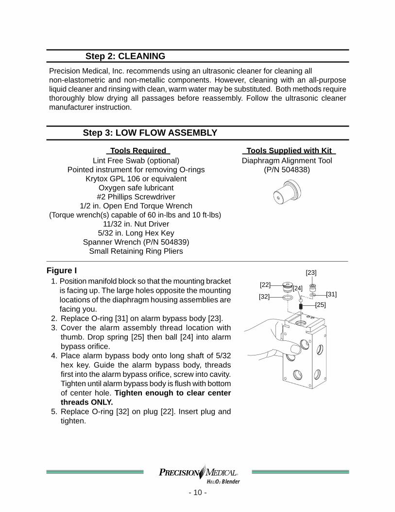
Figure I1. Position manifold block so that the mounting bracket
is facing up. The large holes opposite the mounting locations of the diaphragm housing assemblies are facing you.
2. Replace O-ring [31] on alarm bypass body [23].3. Cover the alarm assembly thread location with
thumb. Drop spring [25] then ball [24] into alarm bypass orifi ce.
4. Place alarm bypass body onto long shaft of 5/32 hex key. Guide the alarm bypass body, threads fi rst into the alarm bypass orifi ce, screw into cavity. Tighten until alarm bypass body is fl ush with bottom of center hole. Tighten enough to clear center threads ONLY.
5. Replace O-ring [32] on plug [22]. Insert plug and tighten.
[32]
[23]
[31][25]
[24][22]

- 11 -HELIO2 Blender
LOW FLOWFigure J
6. Assembling diaphragm housing assemblies.a. Ensure all O-rings have been removed from diaphragm
housing.b. Place diaphragm alignment tool through center hole of
one diaphragm housing.c. Place new diaphragm [29] on top of diaphragm housing,
ensure center pin of diaphragm is in the center of diaphragm alignment tool (P/N 504838).
d. Place other diaphragm housing on top of the one with the diaphragm. Ensure the inlet holes of the diaphragm housings are on the same side.
e. Fasten the two diaphragm housings together using four hex socket head screws [28]. Torque screws to 60 in-lbs.
f. Place four new O-rings [26] on the inlet holes of the diaphragm housings.
g. Remove diaphragm alignment tool.h. Place new O-rings [36] onto each check valve [30].i. By hand, carefully insert new check valve [30] into
diaphragm housing. (Check valves are double threaded) Thread check valves into diaphragm housing using spanner wrench .Check valve must be fl ush with surface of diaphragm housing. DO NOT USE power tool to tighten. Repeat this step for the second check valve.
j. Using two long hex socket head screws [21] secure each diaphragm housing assembly to the manifold block. Torque to 60 in-lbs (6.9 kpm).
k. Repeat steps a - i for remaining diaphragm housing assembly.
[28]QUANTITY - 4
[29]
[26]QUANTITY - 4
[30]QUANTITY - 2
[21]QUANTITY - 2
[36]QUANTITY - 2
Diaphragm Alignment
Tool
Figure K7. Lubricate alarm bypass assembly bore on manifold
block with Krytox GPL 106.8. Using retaining ring pliers install retaining ring [12] in
one side of alarm assembly bore.9. Insert alarm assembly [13] into bore of manifold block.
10. Install remaining retaining ring.11. For Models without manifold block assembly: Replace O-ring [32] on plug [22] then install plug [22]
into bottom hole of manifold block.12. Thread auxiliary outlet assembly [10] to manifold
block, torque to 10 ft-lbs (1.4 kpm).[12]
QUANTITY - 2
[10]
[13][32]
[22]

- 12 -HELIO2 Blender
LOW FLOWFigure L13. Remove and discard outer O-ring [32] from
primary outlet assembly.14. Extrude stem [33] from primary outlet assembly
to expose O-ring on the stem.15. Remove O-ring [34] from stem.16. Discard and replace spring [35].17. Reinsert stem [33] with new spring into primary
outlet body [37]. Extrude stem and install O-ring [34].18. Replace O-ring [32] on outside of primary outlet
body [37].19. Reinstall primary outlet assembly torque to
10 ft-lbs (1.4 kpm).
[32]
[33] [35]
[34]
[37]Primary Outlet Assembly
Figure M20. Start threads of new alarm assembly [11] by hand,
tighten with spanner wrench, ensure not to bend reed.
21. Attach bottom cover [6] using four flat head screws [2].
22. Install new oxygen inlet assembly [5] torque to 10 ft-lbs (1.4 kpm). Oxygen inlet assembly has left handed threads.
23. Install new heliox inlet assembly [4], torque to 10 ft-lbs (1.4 kpm).
[6]
[2]QUANTITY- 4
[4]
[5]
[11]
Spanner Wrench(P/N 504839)
Figure N24. Lubricate proportioning valve bore with Krytox GPL 106.25. Align the (3) holes on the proportioning valve assembly
[16] equal distance between the (2) plugs and push in. *Reference drawing below.
26. Replace washer [19] and phillips head screw [18].27. Place new resistance ring [17] in its place on the
proportioning valve assembly.*Proportional valve assembly inserted, with the
“L” stamped on back for Low Flow Model.plugs
[16]
[18][19]
[17]
The “L” is stamped on the back for LOW Flow models

- 13 -HELIO2 Blender
Step 4: TEST
Equipment Required Medical Heliox Supply
Medical Oxygen SupplyCalibrated Oxygen Analyzer / Monitor
Flowmeter 0 to 70 lpm or greaterCalibrated Pressure Gauges 0 to 100 psi
Regulators / Tubing / Hoses
Tools RequiredPhillips Screwdriver
Torque Driver capable of 10 in-lbsAdjustable Wrench
Retaining Ring PliersNut Driver
Typical Test Confi guration Diagram
Compressed Heliox Supply
Adjustable 0-100 psi
(0-6.89 bar)
Pressure Gauge0-100 psi
(0-6.89 bar)
BlenderPressure Gauge
0-100 psi(0-6.89 bar)
Oxygen Supply
Adjustable 0-100 psi
(0-6.89 bar)
Oxygen Analyzer
Oxygen Flowmeter 0-70 lpm
T - Fitting
INSTRUCTIONS FOR TESTINGA. Heliox and Oxygen Supply Setup
Both gas supplies must be clean and dry per the specifi cations outlined in this manual and have the ability to generate up to 100 psi (6.89 bar) for both the heliox and oxygen inlet pressures. Verify and record the value of the heliox tank concentration prior to connecting heliox hose to tank.

- 14 -HELIO2 Blender
B. Blender Setup1. Mount the Blender into a secured mating wall or pole bracket in an upright position.2. Secure the heliox and oxygen hoses to the corresponding Blender inlets.3. Attach a oxygen fl owmeter capable of 0-70 lpm to the auxiliary outlet on the
Blender.4. Attach a t-fi tting to the outlet of the fl owmeter.5. Attach an Oxygen Analyzer/Monitor to the one outlet on the t-fi tting.6. The system is now ready for an initial performance test.
C. Initial Performance TestNOTE: Before pressurizing, make sure proportioning valve assembly is secure and
screw is tightened.1. Perform calibration on Oxygen Analyzer/Monitor per the manufacture’s instructions
prior to testing the Blender.2. Set heliox and oxygen pressures to 50 psi (3.45 bar) each.
NOTE: Turn OFF and check for leak by watching for pressure drops on pressure gauges. Assure Bleed Flow Valve is not engaged.
3. An initial pressure drop may occur, no further drop in pressure should occur.4. If continued pressure drop is observed, troubleshoot by using a commercial leak
detector to fi nd source of leak and refer to Section 4: TROUBLESHOOTING for further instructions.
5. Use a lint free dry cloth to wipe Blender clean of commercial leak detector.6. Ensure both inlet pressures are at 50 psi.7. Replace the top cover.
NOTE: DO NOT install the four (4) mounting screws until the end of the Final Test, or after satisfactory completion of the Performance Check. Refer to the “OPERATING INSTRUCTIONS” in Users Manual.
8. Set fl owmeter to 3-3.5 lpm.9. Set the Blender to 60% FIO2 with Oxygen Analyzer/Monitor, this value should
remain within 3.0% of original reading throughout the following test.a. Set fl owmeter to 30-30.5 lpm, check concentration reading.b. Set fl owmeter back to 3-3.5 lpm.c. Set heliox inlet pressure to 50 psi (3.45 bar) and the oxygen inlet pressure to
43 psi (2.96 bar) adjust fl ow to 3-3.5 lpm, check concentration reading.d. Set heliox inlet pressure to 43 psi (2.96 bar) and the oxygen inlet pressure to
50 psi (3.45 bar) adjust fl ow to 3-3.5 lpm, check concentration reading.e. If the Oxygen Analyzer/Monitor setting does not remain within 3.0% of the
original reading, then replace one or both diaphragm housing assemblies.
- 15 -HELIO2 Blender
D. Reverse Gas Flow Procedure(Reference Operational Verifi cation Procedure #’s 2 & 3 in Table, page 16 or 27.)
1. Assure Bleed Flow Valve is not engaged. Disconnect the oxygen hose from the gas source. Remove all outlet connections from the Blender to ensure that there is no outlet fl ow.
2. Place the free end of the oxygen supply hose under water. Gradually increase the heliox supply pressure from 30 -75 psi (2.07- 5.17 bar), check for leakage past the oxygen inlet check valve.
3. Replace the Duckbill Check Valve in the oxygen inlet if leakage is >100 ml/min.4. Repeat steps 1-3 to check for leakage past the heliox inlet check valve. 5. Reconnect the heliox inlet hose and adjust both supply pressures back to
standard inlet pressure.
E. Setup of PROPORTIONING VALVE ASSEMBLY1. Set heliox and oxygen inlet pressures to 50 psi (3.45 bar).2. Set fl ow to 15 lpm, measured with oxygen fl owmeter.3. Turn Adjustment Shaft counterclockwise until the Oxygen Analyzer/Monitor displays
a concentration equal to that of the source heliox (±0.2), reference Part A in Setup.4. Attach knob guide assembly onto adjustment shaft of proportioning valve assembly
so that the knob stop rests against the screw. Ensure knob stop aligns with the slot in the resistance ring.
5. While applying downward pressure to the two (2) screws on the knob guide assembly, attach nut to adjustment shaft using nut driver.
6. Turn knob guide fully clockwise, Oxygen Analyzer/Monitor display should be equal to concentration of source oxygen (±0.4).
7. Turn knob guide back to 20 or 30% position to ensure no drift from original reading (±0.4).
8. Torque nut to adjustment shaft and tighten to 10 in-lbs using a torque driver.9. Snap in knob back into knob guide, pay close attention to the key location of the
knob.10. Set knob to 12 o’clock position.11. Replace the top cover. NOTE: DO NOT install the four (4) mounting screws until the end of the Final Test.
F. Final Test Complete Operation Verifi cation Procedure as per the test table, page16 or 27. Record test results in the test table. When Final Test is complete replace top cover and install the four (4) mounting screws
into cover.
NOTE: Operation Verifi cation Procedure should be performed at least once a year.

- 16 -HELIO2 Blender
USA and CANADA ONLYLOW Flow Operation Verifi cation Procedure
(50 psi / 3.45 bar MODELS)Serial No.
SEQ#
DIAL SET
Oxygen%
OXYGEN PRESS
±1.0
HELIOXPRESS
±1.0FLOWMETER
SET TOlpm ±0.2
AUXILIARYBLEED FUNCTION TARGET
VALUEACTUALVALUE
psi bar psi bar
1 ANY 50 3.45 50 3.45 closed closed leak <2 psi / 2 MIN
*2 60 75 5.17 0 0 0 closed back fl ow <100 ml/min
*3 60 0 0 75 5.17 0 closed back fl ow <100 ml/min
4 20 or 30 50 3.45 50 3.45 3 closed end point (±0.2)Source Value
5 40 50 3.45 50 3.45 3 closed set point 37.0%-43.0%
6 60 50 3.45 50 3.45 3 closed set point 57.0%-63.0%7 80 50 3.45 50 3.45 3 closed set point 77.0%-83.0%
8 100 50 3.45 50 3.45 3 closed end point (±0.4)Source Value
9 60 50 3.45 50 3.45 1 open set point 57.0%-63.0%10 60 60 4.14 67 4.62 1 open set point 57.0%-63.0%11 60 60 4.14 50 3.45 1 open set point 57.0%-63.0%
12 60 50 3.45Slowly reduce to 30
Slowly reduce to 2.07
3 closed Alarm ON
30.0± 2.0 psi
13 60 50 3.45
SlowlyIncrease
until alarm shuts off
3 closed Alarm OFF
45.0 psi MAX
14 60Slowly
Reduce to 30
Slowly Reduce to 2.07
50 3.45 3 closed Alarm ON
30.0± 2.0 psi
15 60
SlowlyIncrease
until alarm shuts off
50 3.45 3 closed Alarm OFF
45.0 psiMAX
16 60 50 3.45 50 3.45 MAX closed fl ow rate 30.0 lpm MIN
17 60 50 3.45 0 MAX closed fl ow rate 30.0 lpm MIN
18 60 0 50 3.45 MAX closed fl ow rate 30.0 lpm MIN
19 60 50 3.45 50 3.45 MAX open fl ow rate 30.0 lpm MIN
* Reference, Letter D. (Reverse Gas Flow Procedure)

- 17 -HELIO2 Blender
II. HIGH FLOW (PM5500 Model) Step 1: DISASSEMBLY
Tools Required
#2 Phillips Screwdriver #3 Phillips Screwdriver 1/2 in. Open End WrenchSpanner Wrench (P/N 504839)
11/32 in. Nut Driver5/32 in. Long Hex KeySmall Retaining Ring pliers
Figure A1. Rotate dial [1] to the 12 o’clock position.2. Remove the two fl at head screws [2] on each
side of the top cover [3].3. Remove top cover by pulling upwards. The cover will not come off unless the dial
is at the 12 o’clock position.
[1]
[2]QUANTITY - 4
[3]
Figure B4. Use a ½ in. open end wrench to unscrew and
remove the heliox [4] oxygen [5] inlet assemblies and primary [9] outlet assemblies from bottom of the Blender. Oxygen inlet has left hand threads.
5. If manifold outlet assembly is present, unscrew the stem using a 5/32 hex key and holding the manifold outlet assembly to the bottom of the Blender.
6. Remove the four fl at head screws [2] from bottom cover [6].
7. Remove bottom cover.
[5]
[4]
[2]QUANTITY - 4
[6]
[9]

- 18 -HELIO2 Blender
HIGH FLOW
Figure C 8. Remove dial [7] by pulling dial away from
manifold block [8].9. Remove the auxiliary [10] outlets (auxiliary
contains Blue Muffl er [38]) by using a ½ in. open end wrench to unscrew.
10. Use spanner wrench (P/N 504839) to unscrew and remove audio alarm assembly [11] from the bottom of the manifold block.
[8]
[10]
[11]
[7]
[38]contained in [10]
Figure D11. Use small retaining ring pliers to remove
retaining rings [12] from each side of the alarm assembly [13]. Push the alarm assembly through to remove the assembly from manifold block.
[12]QUANTITY - 2
[13]
Figure E12. Using a 11/32 in. nut driver or socket, loosen
the nut [14] (ONLY two turns) holding the knob guide [15] on the proportioning valve assembly [16]. Slide knob guide assembly from proportioning valve assembly shaft. Slide resistance ring [17] from proportioning valve assembly.
13. Remove phillips head screw [18] and washer [19] from side of proportioning valve assembly.
14. Replace knob guide assembly and tighten the nut.
15. Pull knob guide assembly to remove proportioning valve assembly from manifold block. Again, loosen the nut (ONLY two turns) holding the knob guide to the proportioning valve assembly, remove knob guide from proportioning valve assembly shaft.
[14][15]
[16][18]
[19]
[17]

- 19 -HELIO2 Blender
HIGH FLOWFigure F16. Remove each diaphragm housing assembly [20]
from the manifold by removing the two hex socket head screws [21] on the top of each diaphragm housing with 5/32 hex key.
[20]QUANTITY - 2
[21]QUANTITY - 4
Figure G17. Using 5/32 in. long hex wrench, unscrew and remove
plugs [22] from the side and back of the manifold block. (For High Flow models with a manifold outlet assembly remove plug from left side of manifold block instead of from the bottom of the manifold block.)
18. Remove rear plug [22] from the back of the manifold block. Insert a long 5/32 hex key through rear plug opening, unscrew and remove the alarm bypass body [23], ball [24] and spring [25].
QUANTITY - 2
[23][25]
[24] [22]
[22]
[22]
Figure H19. Remove and discard the two O-rings [26] from the
bottom of each of the diaphragm housings [27].20. Remove the four hex socket head screws [28]
holding diaphragm housings together.21. Remove and discard the diaphragm [29].22. Using spanner wrench, remove and discard check
valves [30]. Ensure inner O-ring is removed from diaphragm housing.NOTE: If check valve [30] comes apart when
removing it from diaphragm housing, a ¼ in. hex wrench or (#3 Phillips Screwdriver) will be needed to complete removal of the check valve from the diaphragm housing.
23. Repeat steps 19-22 for the remaining diaphragm housing assembly.
24. Make sure all O-rings have been removed from diaphragm housings and check valves.
25. Disassembly is complete.26. Manifold block may be ultrasonically cleaned.
[27]
[26]
QUANTITY - 2
QUANTITY - 4
[28]QUANTITY -4
[29]
[30]QUANTITY- 2
[36]QUANTITY -2

- 20 -HELIO2 Blender
Step 2: CLEANING
Precision Medical, Inc. recommends using an ultrasonic cleaner for cleaning all non-elastometric components. However, cleaning with an all-purpose liquid cleaner and rinsing with clean, warm water may be substituted. Both methods require thoroughly blow drying all passages before reassembly. Follow the manufacturer’s instruction for ultrasonic cleaning.
Step 3: HIGH FLOW ASSEMBLY Tools Required
Lint Free Swab (optional)Pointed instrument for removing O-rings
Krytox GPL 106 or equivalentOxygen safe lubricant#2 Phillips Screwdriver
1/2 in. Open End Torque Wrench(Torque wrench(s) capable of 60 in-lbs and 10 ft-lbs)
11/32 in. Nut Driver5/32 in. Long Hex Key
Spanner Wrench (P/N 504839)Small Retaining Ring Pliers
Tools Supplied Diaphragm Alignment Tool
(P/N 504838)
Figure I1. Position manifold block so that the mounting bracket
is facing up. The large holes opposite the mounting locations of the diaphragm housing assemblies are facing you.
2. Replace O-ring [31] on alarm bypass [23].3. Cover the alarm assembly thread location with thumb.
Drop spring [25] then ball [24] into alarm bypass orifi ce.
4. Place alarm bypass onto long shaft of 5/32 hex key. Guide the alarm bypass, threads fi rst into the alarm bypass orifi ce, screw into cavity. Tighten until alarm bypass is fl ush with bottom of center hole.
Tighten enough to clear center threads ONLY.5. Replace O-ring [32] on plug [22]. Insert plug and
tighten.
[32]
[23]
[31][25]
[24][22]

- 21 -HELIO2 Blender
HIGH FLOWFigure J
6. Assembling diaphragm housing assemblies.a. Ensure all O-rings have been removed from diaphragm
housing.b. Place diaphragm alignment tool through center hole of one
diaphragm housing.c. Place new diaphragm [29] on top of diaphragm housing, ensure
center pin of diaphragm is in the center of tool.d. Place other diaphragm housing on top of the one with
the diaphragm. Ensure the inlet holes of the diaphragm housings are on the same side.
e. Fasten the two diaphragm housings together using four hex socket head screws [28]. Torque screws to 60 in-lbs.
f. Place four new O-rings [26] on the inlet holes of the diaphragm housings.
g. Remove diaphragm alignment tool.h. Place new O-rings [36] onto each check valve [30].i. By hand, carefully insert new check valve [30] into diaphragm
housing. (Check valves are double threaded). Thread into diaphragm housing using spanner wrench, Check valve must be fl ush with surface of diaphragm housing. DO NOT USE power tool to tighten. Repeat this step for the second check valve.
j. Using two long hex socket head screws [21] secure each diaphragm housing assembly to the manifold block. Torque to 60 in-lbs (6.9 kpm).
k. Repeat steps a - i for remaining diaphragm housing assembly.
[28]QUANTITY - 4
[29]
[26]QUANTITY - 4
[30]QUANTITY - 2
[21]QUANTITY - 2
[36]QUANTITY - 2
Diaphragm Alignment
Tool
Figure K7. Lubricate alarm bypass assembly bore on manifold
block with Krytox GPL 106.8. Using retaining ring pliers install retaining ring [12] in
one side of alarm assembly bore.9. Insert alarm assembly [13] into bore of manifold block.
10. Install remaining retaining ring.11. Thread auxiliary outlet assembly [10] to manifold block,
torque to 10 ft-lbs (1.4 kpm).
[12]QUANTITY - 2
[10]
[13]

- 22 -HELIO2 Blender
HIGH FLOWFigure L12. Replace O-ring [32] on plug [22]. Install plug and
tighten.
[22]
[32]
Figure M13. Start threads of new alarm assembly [11] by hand,
tighten with spanner wrench, ensure not to bend reed.14. Attach bottom cover [6] using four fl at head screws [2].15. Install new heliox inlet assembly [4], torque to 10 ft-lbs
(1.4 kpm).16. Install new oxygen inlet assembly [5] torque to 10 ft-lbs
(1.4 kpm). Oxygen inlet assembly has left handed threads.
17. Remove and discard outer O-ring [32] from primary outlet body [37].
18. Extrude stem [33] from primary outlet body [37] to expose O-ring on the stem.
19. Remove O-ring [34] from stem.20. Discard and replace spring [35].21. Reinsert stem [33] with new spring into primary outlet
body [37]. Extrude stem and install O-ring [34].22. Replace O-ring [32] on outside of primary outlet assembly.23. Reinstall primary outlet assembly torque to 10 ft-lbs
(1.4 kpm).
[6]
[2]QUANTITY- 4
[4]
[5]
[11]
Spanner Wrench(P/N 504839)
[32][34]
[33]
[35]
[37]
Primary Outlet Assembly
Figure N24. Lubricate proportioning valve bore with Krytox GPL 106.25. Align the (3) holes on the proportioning valve assembly
[16] equal distance between the (2) plugs and push in. *Reference drawing below.
26. Replace washer [19] and phillips head screw [18].27. Place new resistance ring [17] in its place on the
proportioning valve assembly.*Proportional valve assembly inserted, with the
“H” stamped on back for High Flow Model.plugs
[16]
[18][19]
[17]
The “H” is stamped on the back for HIGH Flow models
- 23 -HELIO2 Blender
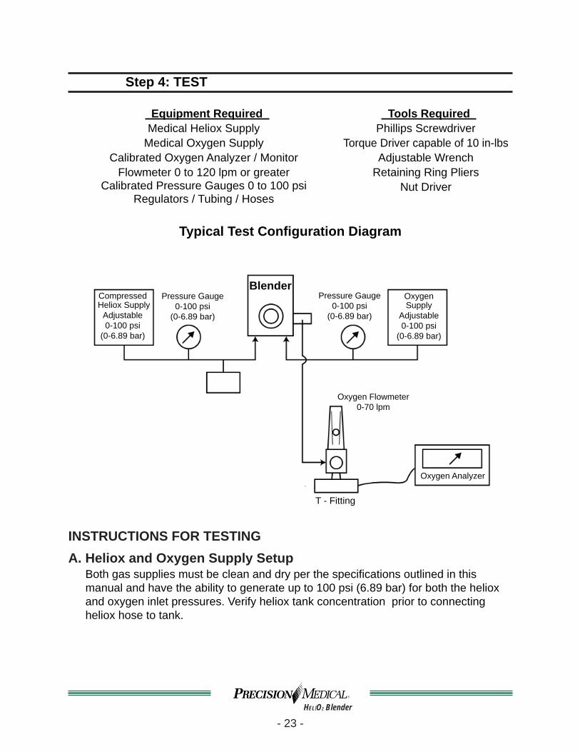
Step 4: TEST
Equipment Required Medical Heliox Supply
Medical Oxygen SupplyCalibrated Oxygen Analyzer / Monitor
Flowmeter 0 to 120 lpm or greaterCalibrated Pressure Gauges 0 to 100 psi
Regulators / Tubing / Hoses
Tools Required Phillips Screwdriver
Torque Driver capable of 10 in-lbsAdjustable Wrench
Retaining Ring PliersNut Driver
Typical Test Confi guration Diagram
Compressed Heliox Supply
Adjustable 0-100 psi
(0-6.89 bar)
Pressure Gauge0-100 psi
(0-6.89 bar)
BlenderPressure Gauge
0-100 psi(0-6.89 bar)
Oxygen Supply
Adjustable 0-100 psi
(0-6.89 bar)
Oxygen Analyzer
Oxygen Flowmeter 0-70 lpm
T - Fitting
INSTRUCTIONS FOR TESTINGA. Heliox and Oxygen Supply Setup
Both gas supplies must be clean and dry per the specifi cations outlined in this manual and have the ability to generate up to 100 psi (6.89 bar) for both the heliox and oxygen inlet pressures. Verify heliox tank concentration prior to connecting heliox hose to tank.

- 24 -HELIO2 Blender
B. Blender Setup1. Mount the Blender into a secured mating wall or pole bracket in an upright position.2. Secure the heliox and oxygen hoses to the corresponding Blender inlets.3. Attach a oxygen fl owmeter capable of 0-120 lpm to the auxiliary outlet on the
Blender.4. Attach a t-fi tting to the outlet of the fl owmeter.5. Attach an Oxygen Analyzer/Monitor to the one outlet on the t-fi tting.6. The system is now ready for an initial performance test.
C. Initial Performance TestNOTE: Before pressurizing, make sure proportioning valve assembly is secure and
screw is tightened.1. Perform calibration on Oxygen Analyzer/Monitor per the manufacture’s instructions
prior to testing the Blender.2. Set heliox and oxygen pressures to 50 psi (3.45 bar) each.
NOTE: Turn OFF and check for leak by watching for pressure drops on pressure gauges. Assure Bleed Flow Valve is not engaged.
3. An initial pressure drop may occur, no further drop in pressure should occur.4. If continued pressure drop is observed, troubleshoot by using a commercial leak
detector to fi nd source of leak and refer to Section 4: TROUBLESHOOTING for further instructions.
5. Use a lint free dry cloth to wipe Blender clean of commercial leak detector.6. Ensure both inlet pressures are at 50 psi.7. Replace the top cover.
NOTE: DO NOT install the four (4) mounting screws until the end of the Final Test, or after satisfactory completion of the Performance Check. Refer to the “OPERATING INSTRUCTIONS” in Users Manual.
8. Set fl owmeter to 15 lpm.9. Set the Blender to 60% FIO2 with Oxygen Analyzer/Monitor, this value should
remain within 3.0% of original reading throughout the following test.a. Set fl owmeter to 30-30.5 lpm, check concentration reading.b. Set fl owmeter back to 3-3.5 lpm.c. Set heliox inlet pressure to 50 psi (3.45 bar) and the oxygen inlet pressure to
43 psi (2.96 bar) adjust fl ow to 3-3.5 lpm, check concentration reading.d. Set heliox inlet pressure to 43 psi (2.96 bar) and the oxygen inlet pressure to
50 psi (3.45 bar) adjust fl ow to 3-3.5 lpm, check concentration reading.e. If the Oxygen Analyzer/Monitor setting does not remain within 3.0% of the
original reading, then replace one or both diaphragm housing assemblies.

- 25 -HELIO2 Blender
D. Reverse Gas Flow Procedure(Reference Operational Verifi cation Procedure #’s 2 & 3 in Table, page 26 or 27.)
1. Assure Bleed Flow Valve is not engaged. Disconnect the oxygen hose from the gas source. Remove all outlet connections from the Blender to ensure that there is no outlet fl ow.
2. Place the free end of the oxygen supply hose under water. Gradually increase the heliox supply pressure from 30 -75 psi (2.07- 5.17 bar), check for leakage past the oxygen inlet check valve.
3. Replace the Duckbill Check Valve in the oxygen inlet if leakage is >100 ml/min.4. Repeat steps 1-3 to check for leakage past the heliox inlet check valve. 5. Reconnect the heliox inlet hose and adjust both supply pressures back to
standard inlet pressure.
E. Setup of PROPORTIONING VALVE ASSEMBLY1. Set heliox and oxygen inlet pressures to 50 psi (3.45 bar).2. Set fl ow to 15 lpm, measured with oxygen fl owmeter.3. Turn Adjustment Shaft counterclockwise until the Oxygen Analyzer/Monitor displays
a concentration equal to that of the source heliox (±0.2), reference Part A in Setup.4. Attach knob guide assembly onto adjustment shaft of proportioning valve assembly
so that the knob stop rests against the screw. Ensure knob stop aligns with the slot in the resistance ring.
5. While applying downward pressure to the two (2) screws on the knob guide assembly, attach nut to adjustment shaft using nut driver.
6. Turn knob guide fully clockwise, Oxygen Analyzer/Monitor display should be equal to the concentration of source oxygen (±0.4).
7. Turn knob guide back to 20 or 30% position to ensure no drift from original reading (±0.4).
8. Torque nut to adjustment shaft and tighten to 10 in-lbs using a torque driver.9. Snap in knob back into knob guide, pay close attention to the key location of the
knob.10. Set knob to 12 o’clock position.11. Replace the top cover. NOTE: DO NOT install the four (4) mounting screws until the end of the Final Test.
F. Final Test Complete Operation Verifi cation Procedure as per the test table, page 26 or 27. Record test results in the test table. When Final Test is complete replace top cover and install the four (4) mounting screws
into cover.
NOTE: Operation Verifi cation Procedure should be performed at least once a year.

- 26 -HELIO2 Blender
USA and CANADA ONLYHIGH Flow Operation Verifi cation Procedure
(50 psi / 3.45 bar MODELS)Serial No.
SEQ#
DIAL SET
Oxygen%
OXYGEN PRESS
±1.0
HELIOXPRESS
±1.0FLOWMETER
SET TOlpm ±0.2
AUXILIARYBLEED FUNCTION TARGET
VALUEACTUALVALUE
psi bar psi bar
1 ANY 50 3.45 50 3.45 closed closed leak <2 psi / 2 MIN
*2 60 75 5.17 0 0 0 closed back fl ow <100 ml/min
*3 60 0 0 75 5.17 0 closed back fl ow <100 ml/min
4 20 or 30 50 3.45 50 3.45 15 closed end point (±0.2)Source Value
5 40 50 3.45 50 3.45 15 closed set point 37.0%-43.0%
6 60 50 3.45 50 3.45 15 closed set point 57.0%-63.0%7 80 50 3.45 50 3.45 15 closed set point 77.0%-83.0%
8 100 50 3.45 50 3.45 15 closed end point (±0.4)Source Value
9 60 50 3.45 50 3.45 1.5 open set point 57.0%-63.0%10 60 60 4.14 67 4.62 1.5 open set point 57.0%-63.0%11 60 60 4.14 50 3.45 1.5 open set point 57.0%-63.0%
12 60 50 3.45Slowly reduce to 31
Slowly reduce to 2.14
15 closed Alarm ON
31.0± 6.0 psi
13 60 50 3.45
SlowlyIncrease
until alarm shuts off
15 closed Alarm OFF
45.0 psi MAX
14 60Slowly
Reduce to 31
Slowly Reduce to 2.14
50 3.45 15 closed Alarm ON
31.0± 6.0 psi
15 60
SlowlyIncrease
until alarm shuts off
50 3.45 15 closed Alarm OFF
45.0 psiMAX
16 60 50 3.45 50 3.45 MAX closed fl ow rate 120.0 lpm MIN
17 60 50 3.45 0 MAX closed fl ow rate 85.0 lpm MIN
18 60 0 50 3.45 MAX closed fl ow rate 85.0 lpm MIN
19 60 50 3.45 50 3.45 MAX open fl ow rate 120.0 lpm MIN
* Reference, Letter D. (Reverse Gas Flow Procedure)

- 27 -HELIO2 Blender
III. INTERNATIONAL LOW / HIGH Flow Operation Verifi cation Procedure (60 psi / 4.14 bar MODELS)
Serial No.
SEQ#
DIAL SETOxygen%
OXYGEN PRESS
±1.0
HELIOXPRESS
±1.0
FLOWMETERSET TOlpm ±0.2 AUXILIARY
BLEED FUNCTION
TARGET VALUE ACTUAL
VALUE
psi bar psi bar Low Flow
High Flow
Low Flow
High Flow
1 ANY 60 4.14 60 4.14 closed closed leak <2 psi / 2 MIN
*2 60 75 5.17 0 0 0 closed back fl ow <100 ml/min
*3 60 0 0 75 5.17 0 closed back fl ow <100 ml/min
4 20 or 30 60 4.14 60 4.14 3 15 closed end point (±0.2)Source Value
5 40 60 4.14 60 4.14 3 15 closed set point 37.0%-43.0%
6 60 60 4.14 60 4.14 3 15 closed set point 57.0%-63.0%
7 80 60 4.14 60 4.14 3 15 closed set point 77.0%-83.0%
8 100 60 4.14 60 4.14 3 15 closed end point (±0.4)Source Value
9 60 60 4.14 60 4.14 1 1.5 open set point 57.0%-63.0%
10 60 60 4.14 70 4.83 1 1.5 open set point 57.0%-63.0%
11 60 60 4.14 53 3.65 1 1.5 open set point 57.0%-63.0%
12 60 60 4.14SlowlyLowerto 40
SlowlyLowerto 2.76
3 15 closed Alarm ON
42.0±2.0 psi
31.0±6.0 psi
13 60 60 4.14Slowly
Increase to 60
SlowlyIncrease to 4.14
3 15 closed Alarm OFF
55.0 psi MAX
14 60SlowlyLowerto 40
SlowlyLowerto 2.76
60 4.14 3 15 closed Alarm ON
42.0±2.0 psi
31.0±6.0 psi
15 60Slowly
Increase to 60
SlowlyIncrease to 4.14
60 4.14 3 15 closed Alarm OFF
55.0 psi MAX
16 60 60 4.14 60 4.14 MAX closed fl ow rate30.0 lpm MIN
120.0lpmMIN
17 60 60 4.14 0 0 MAX closed fl ow rate30.0 lpm MIN
85.0 lpm MIN
18 60 0 0 60 4.14 MAX closed fl ow rate30.0 lpm MIN
85.0lpm MIN
19 60 60 4.14 60 4.14 MAX open fl ow rate30.0 lpm MIN
120.0 lpmMIN
* Reference, Letter D. (Reverse Gas Flow Procedure)

- 28 -HELIO2 Blender
SECTION 4: TROUBLESHOOTINGTest #’s Problem Probable Cause Remedy
1
Pressure drop greater than 2 psi in two minutes
Leakage from manifold caused by cut or missing o-ring or due to particulates.
Check ALL manifold connections (inlets, outlets, plugs, proportioning valve, alarm poppet, etc.) with oxygen leak detector to fi nd source of leakage; if leak is found, remove appropriate parts and clean seal area and o-rings and/or replace appropriate o-ring.
Leakage from diaphragm housing caused by damaged diaphragm or particulates.
Check diaphragm housings with oxygen leak detector. If leak is found, disassemble diaphragm housing assembly and clean seal area and diaphragm and/or replace diaphragm.
Leakage from check valve/diaphragm housing seal caused by cut or missing o-ring or due to particulates.
Check check-valve/diaphragm housing seal with oxygen leak detector. If leak is found, remove check valve, clean seal area and o-ring and/or replace o-ring. Note: be sure to re-install washer (if present).
Ball not sealing in the alarm bypass. Replace spring and ball in alarm bypass; ensure seal surface is clean.
Auxiliary bleed is open. Close auxiliary bleed by turning and pulling knurled collar away from cover until bleed is closed.
Leakage from one of the outlets. Replace outlet.
2 and 3 Back fl ow leak Faulty inlet. Replace duckbill valve or entire inlet assembly.
4 thru 8
Measured FIO2 values do not meet target values
Outlet fl ow is less than 3 lpm. Adjust fl owmeter to 3 lpm (Note: fl ow must be adjusted after each change in FIO2 setting).
Proportioning valve endpoints are not set correctly.
Set proportioning valve endpoints (see setup procedure in Section E).
Diaphragm blocks not balancing properly.
Refurbish diaphragm block assembly with new diaphragm and check valves. Note: be sure to re-install shim washer under check-valve assembly (if present).
Internal leakage in proportion valve. Remove proportioning valve; clean seal areas and/or replace the two rear o-rings. If necessary, replace proportioning valve assembly.
9 thru 11
Measured FIO2 values do not meet target values
Bleed not open. Open bleed by turning and pushing the knurled collar until it contacts the cover.
Blockage in bleed holes. Replace auxiliary outlet.Internal leak in proportioning valve. Remove proportioning valve; clean seal areas and/
or replace the two rear o-rings. If necessary, replace proportioning valve assembly.
Flow not set to 1 lpm. Adjust fl ow to 1 lpm.Diaphragm blocks not balancing properly. Replace diaphragm block.
12 and14 Alarm not audible and gas is not exiting the alarm vent
Pressure differential not suffi cient to trigger alarm.
Ensure supply pressures are set properly to achieve differential (Low Flow: 18 to 22; High Flow: 13-25).
Alarm not audible and gas is exiting the alarm vent
Faulty alarm. Replace alarm. (See Figure C & M)
13 and 15 Alarm does not turn off after balancing supply pressures
Faulty alarm assembly. Replace alarm assembly. (See Figure D & K)Ball not sealing in the alarm bypass. Replace spring and ball in alarm bypass; ensure
seal surface is clean.
16 thru 19
Measured fl ow values do not meet minimum target values
Gas inlets are restricted. Check appropriate gas inlet(s) for restriction in gas pathway; replace duckbill or entire inlet as necessary.
High fl ow model only: low fl ow inlets installed in place of high-fl ow inlets.
Confi rm that high-fl ow inlets are installed; replace as necessary.
Alarm bypass is threaded too far into manifold block (only applicable to tests 17 and 18).
Replace ball and spring (see Figure I for proper assembly method).
High fl ow models only: wrong ball in alarm bypass block (only applicable to tests 17 and 18).
Confi rm that correct ball is installed in alarm bypass; replace as necessary.

- 29 -HELIO2 Blender
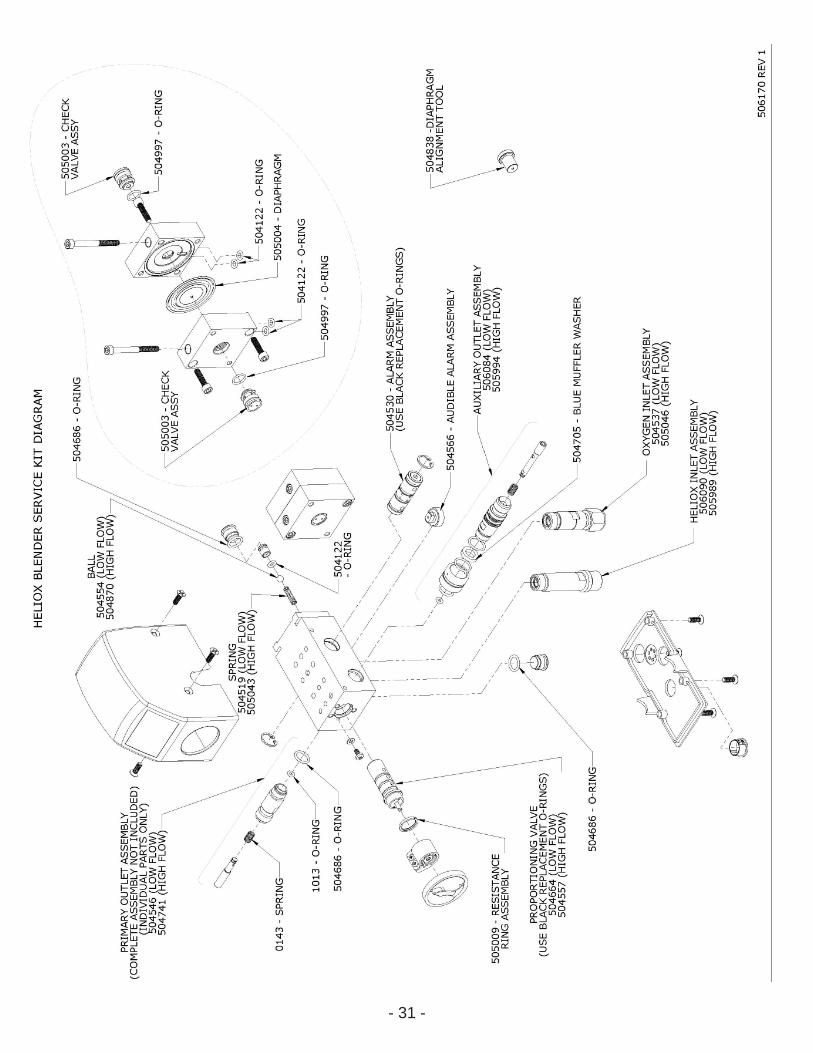
SECTION 5: BLENDER PARTS LIST LOW FLOW PM5400
HIGH FLOWPM5500PART # DESCRIPTION
1 504562 CONTROL KNOB (DIAL)
2 504720 SCREW,FLT HD,#8-32,1/2LG,100DEG
3 504718 TOP COVER
4 506090HELIUM INLET ASSEMBLY
505989
5 504537OXYGEN INLET ASSEMBLY
505046
6 504719 BOTTOM COVER
7 504562 CONTROL KNOB (DIAL)
8 504605 MANIFOLD BLOCK
9504546
PRIMARY OUTLET ASSEMBLY
504741
10 504791AUXILIARY OUTLET ASSEMBLY
504550
11 504566 AUDIO ALARM ASSEMBLY
12 504536 RING, RETAINING,HO TYPE,.562BORE,STL
13 504530 ALARM ASSEMBLY
14 504702 NUT, HEX, LOCK, #8-32
15 504938GUIDE KNOB ASSEMBLY
505030
16 504664 setPROPORTIONING VALVE ASSEMBLY
504557 set
17 505009 RESISTANCE RING
18 504561 SCREW,PAN HD,#6-32,1/4LG,CR,SST
19 504684 WASHER,FLAT,.281,.140,.030,SST
20 *505002 DIAPHRAGM HOUSING ASSEMBLY
21 504526 SCREW,HEX SOC HD,#10-32,2.00LG,SST
22 504528 PLUG
23 504553 ALARM BYPASS BODY
24 504870 BALL,.188 DIA,BUNA-N,70 DUROMETER
25 504519SPRING, ALARM BYPASS
505043
26 504122 O-RING,#008,SILICONE,70 DUROMETER
27 504522 DIAPHRAGM HOUSING
28 504525 SCREW,HEX SOC HD,#10-32,3/4LG,SST
29 505004 DIAPHRAGM
30 505003 CHECK VALVE
31 504122 O-RING,#008,SILICONE,70 DUROMETER
32 504686 O-RING,#013,SILICONE,70 DUROMETER
33 504628STEM,PRIMARY OUTLET
504743
34 1013 O-RING,#006,BUNA-N,70 DUROMETER
35 0143 PRIMARY VALVE SPRING
36 504997 O-RING,10MM X 1.5MM,VITON,75 DUROMETER
37 504547PRIMARY OUTLET BODY
504742
38 504705 BLUE MUFFLER, WASHER (NOT SOLD SEPARATELY, INCLUDED IN 504791 & 504550)
N/A 506125 / 506126 SERVICE KITS - PM5470 / PM5480
N/A 506212 / 506213 SERVICE KITS - PM5570 / PM5580
* NOT sold assembled.

- 30 -HELIO2 Blender
LABEL INFORMATION
Part # Label Description Low Flow PM5400
High FlowPM5500
Location(Blender with dial facing you)
506122Primary Outlet
Left Side on top cover
506019
506008 HELIO2 80-20 Left and Right Side on top cover
506013 HELIO2 70-30
505961Scale 20-100
Bottom Front on top cover
505960
505974Scale, 30-100
Bottom Front on top cover
505973
506011 Warning Top Back on top cover
506004 Face
Top Front on top cover
506003Auxiliary Outlet
Right Side on top cover
506020
506018 Bottom
Bottom Cover
506007 PM5580 Model#, Serial# Bottom Back on rear slide mount
506012 PM5570 Model#, Serial#
506026 PM5480 Model#, Serial# Bottom Back on rear slide mount
506021 PM5470 Model#, Serial#
For customized Blenders with special labels, contact Precision Medical, Inc.
- 31 -HELIO2 Blender

- 32 -HELIO2 Blender
DATE NOTES

Precision Medical, Inc.300 Held Drive
Northampton, PA 18067 USA
Toll Free Tel: 800-272-7285 Toll Free Fax: 800-353-1240 Tel:(+001) 610-262-6090 Fax:(+001) 610-262-6080
506124 Rev0 (E) 11/10/09 Printed in USA