helical antenna for the 2.425ghz wireless networking...
TRANSCRIPT
How to Make a Simple 2.425GHz HelicalAerial for Wireless ISM Band Devices
IntroductionAs some of the readers may know, an effort by members of the Canberra Linux Users Group has been launched to set up aCanberra-wide wireless LAN. This amateur experiment's existence is largely due to the acquisition of many cut-price old style LucentWaveLAN cards being superseded by the IEEE 802.11 standard cards. The cards were cheap but the tile antennas that came withthem are no good for long haul links of more than several hundred metres. On top of this, commercial aerials that can do the job areexpensive, can get rather large and are ugly, especially the conifers. My Mum would not want one on her roof.
Consequently, there is no reason why this aerial couldn't also be used with any other equipment that requires a broad bandwidth inthe 2.425GHz band such as the new 802.11 wireless network cards or video transmitters. If anyone does use the aerial with thesebits of equipment, please let me know!
The idea behind this aerial was for anyone to be able to make their own aerial for point to point links, and do it cheaply. The criteriaare cost effectiveness, ease of construction and durability. Durability is important as you don't want wind, beak cleaning magpies andhighly destructive nibbling cockatoos ruining your Quake III and Unreal Tournament sessions. Birds landing on the aerial have theeffect of severely diminishing the signal, too.
The aerial was derived from information on helical antennas in the ARRL Antenna book.
Any places and shops referenced are in Canberra, Australia.
PartsTo construct one aerial you will need:
1 x 0.55 metre length of 40mm PVC plumbing pipe (40mm inner, about 42-43mm outer diameter)●
1 x 40mm PVC endcaps●
1 x 150mm PVC endcaps OR a sturdy thick piece of plastic or wood of similar dimensions●
2 x 25mm or 35mm U-bolts●
8 x extra nuts for U-bolts●
8 x extra washers for U-bolts●
1 x 5/16" round head bolt (must be short kind) and nut and washer to suit●
1 x sheet of 0.4 - 0.7mm thick brass shim (sheeting) large enough to cut a 130mm diameter circle OR a suitably largepiece of aluminium from a Sara Lee (or like) apple pie tin. Plain old aluminium foil is too thin and tears when you drilland cut it..
●
Several metres of 1mm enamelled copper wire (can be greater but not much smaller than 1mm)●
1 x panel mount N-connector (the kind with a square base and 4 screw holes, Dick Smith has them)●
3 x screws, nuts and washers to suit N-connector●
Printouts of the PDF files below●
Slow drying Araldite●
Loctite 424 or similar (superglue could do or a hotglue gun would do)●
sealing silicone●
masking tape●
Tools needed are:Hacksaw●
Big flat file●
Big strong wire cutters●
Spanner to suit 5/16" nuts●
Philips screwdriver for the N-connector screws●
Drill●
Plethora of drill bits from small to really big●
Helical Antenna for the 2.425GHz Wireless Networking Cards
http://users.bigpond.net.au/jhecker/ (1 of 13) [12/3/2001 11:11:48 AM]
Soldering iron●
Scissors (but not the Good Scissors, because you will wreck those and your Mum will kill you.)●
Stanley knife or scalpel●
The endcaps must have a completely flat base. Hardware House and BBC have these as do Tradesmans Warehouse in Fyshwick(next to Dick Smith) where I got mine. Canberra Southern Plumbing had caps with big dimples in the centre right where they wouldobstruct the placement of a bolt.
You can get the U-bolts and nuts and washers from Hardware House or BBC.
The brass shim is available in whatever length you need from Belconnen Metal Centre. They have cans of the stuff rolled up. Tuggeranong Metal Centre should have it too.
Construction
-Print and cut out the templates in the PDF template file. circle.pdf and rhspiral.pdf or lhspiral.pdf Use rhspiral for righthanded spiral helicals and lhspiral for left handed spirals. You will need the circle to make the ground plane (reflector), unlessyou can prescribe a good 130mm diameter circle yourself with a ruler and circumference.
UPDATE! - Download HelixCalc from the theory section below to design your own templates.
-Cut a length of 40mm PVC to 550mm (55cm).
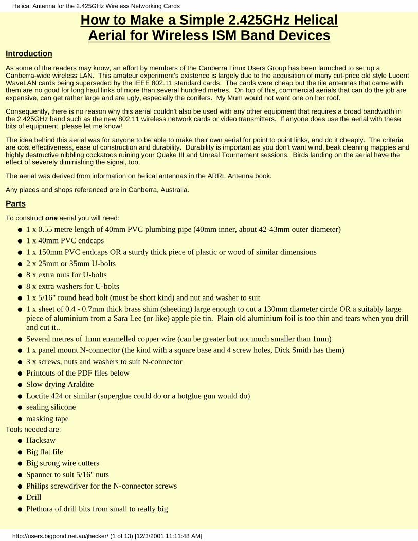
-Wrap the winding template around the PVC tube and tape the seam together. It doesn't matter if you use the RIGHT or LEFThanded template so long as the helical at the other end is the same. Make sure the spirals line up the at the seam. A small gapat the seam is OK. If you combine a left handed aerial with a right handed aerial then you'll get virtually no usable signal.
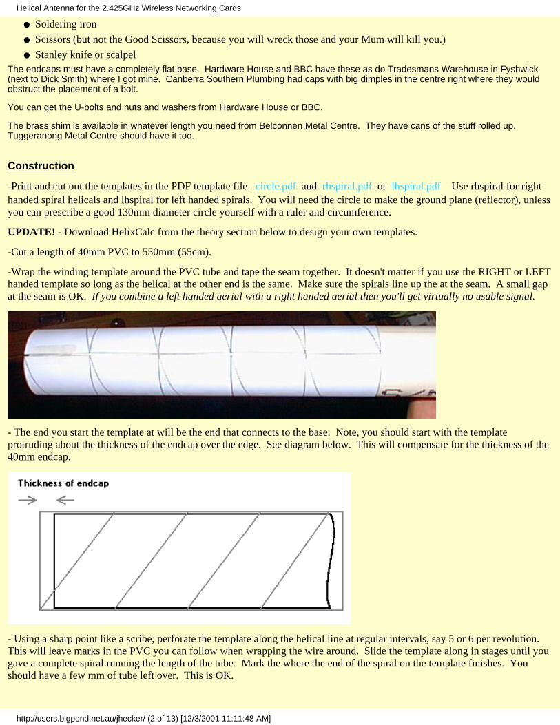
- The end you start the template at will be the end that connects to the base. Note, you should start with the templateprotruding about the thickness of the endcap over the edge. See diagram below. This will compensate for the thickness of the40mm endcap.
- Using a sharp point like a scribe, perforate the template along the helical line at regular intervals, say 5 or 6 per revolution. This will leave marks in the PVC you can follow when wrapping the wire around. Slide the template along in stages until yougave a complete spiral running the length of the tube. Mark the where the end of the spiral on the template finishes. Youshould have a few mm of tube left over. This is OK.
Helical Antenna for the 2.425GHz Wireless Networking Cards
http://users.bigpond.net.au/jhecker/ (2 of 13) [12/3/2001 11:11:48 AM]

- Take the 1mm wire spool and using something like superglue or Loctite 424 attach the end of the wire to where the spiralends at the tube (the end point described above.). Slowly wind the wire around the tube, following the spiral indentations. Atfairly regular intervals like a 1/2 or 1/3 turn add some more glue to hold the wire in place.
- As you approach the base end don't glue down the last turn and leave plenty of excess wire (10cm or so) hanging off the end. Let the glue dry.
- Cut out from the brass shim or Sara Lee pie tin the 130mm diameter circle (from circle.pdf).
- Drill holes in the 150mm endcap and 130mm sheet to allow for the centre bolt and N connector holes to come though. Imarked the positions of everything by centreing the base of the 40mm endcap onto the base of the 150mm endcap and drawingthe circumference as you can see below. I then positioned the N connector over the outline to see where it needed to fit, seeingas the N connector stub has to be right on the outer edge of the 40mm tube.
- Take the 40mm PVC endcap and cut off a section big enough to allow the N connector stub and three nut holes room to pokethrough. The sketch below will give you an idea of how much you want to cut off to allow for the stub and bolt holes to fitwhen it all comes together.
- Drill a hole in the endcap suitable for the 5/16" bolt. With the side cut off and hole drilled it should look like thus:
Helical Antenna for the 2.425GHz Wireless Networking Cards
http://users.bigpond.net.au/jhecker/ (3 of 13) [12/3/2001 11:11:48 AM]
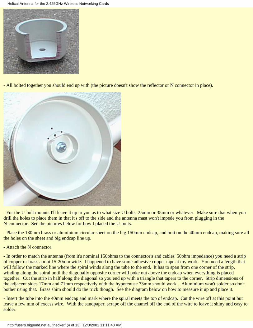
- All bolted together you should end up with (the picture doesn't show the reflector or N connector in place).
- For the U-bolt mounts I'll leave it up to you as to what size U bolts, 25mm or 35mm or whatever. Make sure that when youdrill the holes to place them in that it's off to the side and the antenna mast won't impede you from plugging in theN-connector. See the pictures below for how I placed the U-bolts.
- Place the 130mm brass or aluminium circular sheet on the big 150mm endcap, and bolt on the 40mm endcap, making sure allthe holes on the sheet and big endcap line up.
- Attach the N connector.
- In order to match the antenna (from it's nominal 150ohms to the connector's and cables' 50ohm impedance) you need a stripof copper or brass about 15-20mm wide. I happened to have some adhesive copper tape at my work. You need a length thatwill follow the marked line where the spiral winds along the tube to the end. It has to span from one corner of the strip,winding along the spiral until the diagonally opposite corner will poke out above the endcap when everything is placedtogether. Cut the strip in half along the diagonal so you end up with a triangle that tapers to the corner. Strip dimensions ofthe adjacent sides 17mm and 71mm respectively with the hypotenuse 73mm should work. Aluminium won't solder so don'tbother using that. Brass shim should do the trick though. See the diagram below on how to measure it up and place it.
- Insert the tube into the 40mm endcap and mark where the spiral meets the top of endcap. Cut the wire off at this point butleave a few mm of excess wire. With the sandpaper, scrape off the enamel off the end of the wire to leave it shiny and easy tosolder.
Helical Antenna for the 2.425GHz Wireless Networking Cards
http://users.bigpond.net.au/jhecker/ (4 of 13) [12/3/2001 11:11:48 AM]
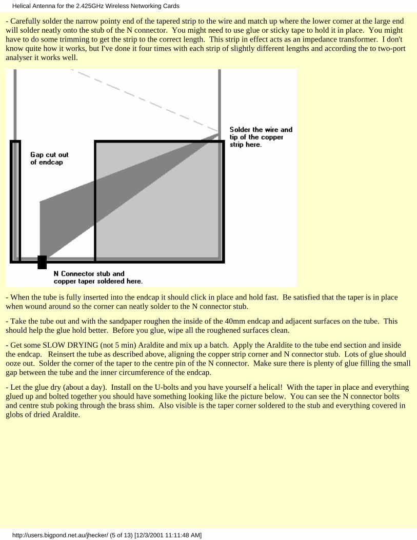
- Carefully solder the narrow pointy end of the tapered strip to the wire and match up where the lower corner at the large endwill solder neatly onto the stub of the N connector. You might need to use glue or sticky tape to hold it in place. You mighthave to do some trimming to get the strip to the correct length. This strip in effect acts as an impedance transformer. I don'tknow quite how it works, but I've done it four times with each strip of slightly different lengths and according the to two-portanalyser it works well.
- When the tube is fully inserted into the endcap it should click in place and hold fast. Be satisfied that the taper is in placewhen wound around so the corner can neatly solder to the N connector stub.
- Take the tube out and with the sandpaper roughen the inside of the 40mm endcap and adjacent surfaces on the tube. Thisshould help the glue hold better. Before you glue, wipe all the roughened surfaces clean.
- Get some SLOW DRYING (not 5 min) Araldite and mix up a batch. Apply the Araldite to the tube end section and insidethe endcap. Reinsert the tube as described above, aligning the copper strip corner and N connector stub. Lots of glue shouldooze out. Solder the corner of the taper to the centre pin of the N connector. Make sure there is plenty of glue filling the smallgap between the tube and the inner circumference of the endcap.
- Let the glue dry (about a day). Install on the U-bolts and you have yourself a helical! With the taper in place and everythingglued up and bolted together you should have something looking like the picture below. You can see the N connector boltsand centre stub poking through the brass shim. Also visible is the taper corner soldered to the stub and everything covered inglobs of dried Araldite.
Helical Antenna for the 2.425GHz Wireless Networking Cards
http://users.bigpond.net.au/jhecker/ (5 of 13) [12/3/2001 11:11:48 AM]
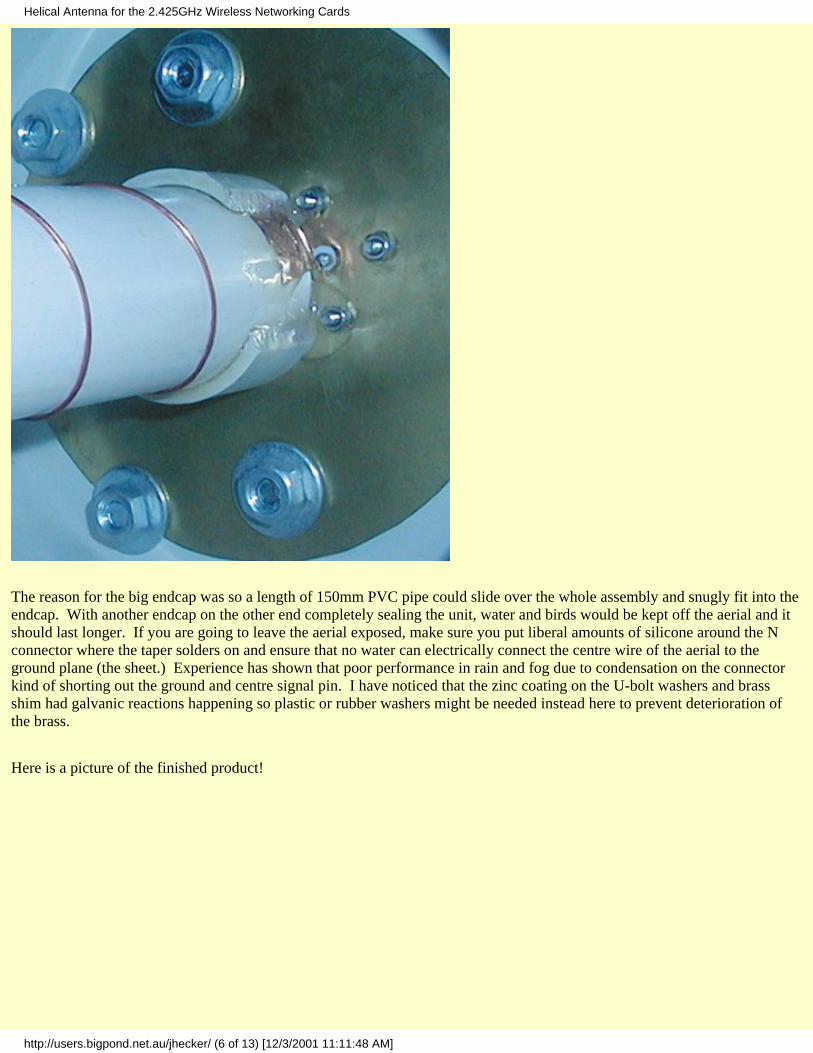
The reason for the big endcap was so a length of 150mm PVC pipe could slide over the whole assembly and snugly fit into theendcap. With another endcap on the other end completely sealing the unit, water and birds would be kept off the aerial and itshould last longer. If you are going to leave the aerial exposed, make sure you put liberal amounts of silicone around the Nconnector where the taper solders on and ensure that no water can electrically connect the centre wire of the aerial to theground plane (the sheet.) Experience has shown that poor performance in rain and fog due to condensation on the connectorkind of shorting out the ground and centre signal pin. I have noticed that the zinc coating on the U-bolt washers and brassshim had galvanic reactions happening so plastic or rubber washers might be needed instead here to prevent deterioration ofthe brass.
Here is a picture of the finished product!
Helical Antenna for the 2.425GHz Wireless Networking Cards
http://users.bigpond.net.au/jhecker/ (6 of 13) [12/3/2001 11:11:48 AM]
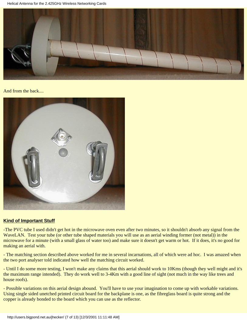
And from the back....
Kind of Important Stuff
-The PVC tube I used didn't get hot in the microwave oven even after two minutes, so it shouldn't absorb any signal from theWaveLAN. Test your tube (or other tube shaped materials you will use as an aerial winding former (not metal)) in themicrowave for a minute (with a small glass of water too) and make sure it doesn't get warm or hot. If it does, it's no good formaking an aerial with.
- The matching section described above worked for me in several incarnations, all of which were ad hoc. I was amazed whenthe two port analyser told indicated how well the matching circuit worked.
- Until I do some more testing, I won't make any claims that this aerial should work to 10Kms (though they well might and it'sthe maximum range intended). They do work well to 3-4Km with a good line of sight (not much in the way like trees andhouse roofs).
- Possible variations on this aerial design abound. You'll have to use your imagination to come up with workable variations. Using single sided unetched printed circuit board for the backplane is one, as the fibreglass board is quite strong and thecopper is already bonded to the board which you can use as the reflector.
Helical Antenna for the 2.425GHz Wireless Networking Cards
http://users.bigpond.net.au/jhecker/ (7 of 13) [12/3/2001 11:11:48 AM]
Theory
The design for this aerial was derived from the good ol' ARRL Antenna Handbook. From chapter 19 are a bunch of helicaldesigns and some maths detailing how to paramterise and gauge the performance of the aerial.
I have lost my original design notes, so I am rederiving this from the PDF files and measuring the aerials I made.
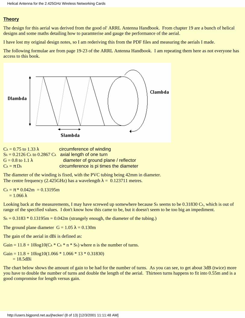
The following formulae are from page 19-23 of the ARRL Antenna Handbook. I am repeating them here as not everyone hasaccess to this book.
Cλ = 0.75 to 1.33 λ circumference of windingSλ = 0.2126 Cλ to 0.2867 Cλ axial length of one turnG = 0.8 to 1.1 λ diameter of ground plane / reflectorCλ = π Dλ circumference is pi times the diameter
The diameter of the winding is fixed, with the PVC tubing being 42mm in diameter.The centre frequency (2.425GHz) has a wavelength λ = 0.123711 metres.
Cλ = π * 0.042m = 0.13195m = 1.066 λ
Looking back at the measurements, I may have screwed up somewhere because Sλ seems to be 0.31830 Cλ, which is out ofrange of the specified values. I don't know how this came to be, but it doesn't seem to be too big an impediment.
Sλ = 0.3183 * 0.13195m = 0.042m (strangely enough, the diameter of the tubing.)
The ground plane diameter G = 1.05 λ = 0.130m
The gain of the aerial in dBi is defined as:
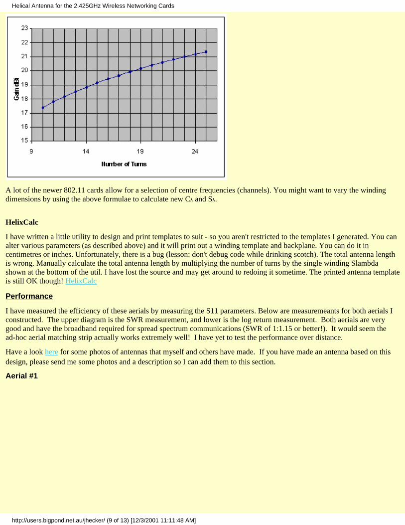
Gain = 11.8 + 10log10(Cλ * Cλ * n * Sλ) where n is the number of turns.
Gain = 11.8 + 10log10(1.066 * 1.066 * 13 * 0.31830) = 18.5dBi
The chart below shows the amount of gain to be had for the number of turns. As you can see, to get about 3dB (twice) moreyou have to double the number of turns and double the length of the aerial. Thirteen turns happens to fit into 0.55m and is agood compromise for length versus gain.
Helical Antenna for the 2.425GHz Wireless Networking Cards
http://users.bigpond.net.au/jhecker/ (8 of 13) [12/3/2001 11:11:48 AM]
A lot of the newer 802.11 cards allow for a selection of centre frequencies (channels). You might want to vary the windingdimensions by using the above formulae to calculate new Cλ and Sλ.
HelixCalc
I have written a little utility to design and print templates to suit - so you aren't restricted to the templates I generated. You canalter various parameters (as described above) and it will print out a winding template and backplane. You can do it incentimetres or inches. Unfortunately, there is a bug (lesson: don't debug code while drinking scotch). The total antenna lengthis wrong. Manually calculate the total antenna length by multiplying the number of turns by the single winding Slambdashown at the bottom of the util. I have lost the source and may get around to redoing it sometime. The printed antenna templateis still OK though! HelixCalc
Performance
I have measured the efficiency of these aerials by measuring the S11 parameters. Below are measuremeants for both aerials Iconstructed. The upper diagram is the SWR measurement, and lower is the log return measurement. Both aerials are verygood and have the broadband required for spread spectrum communications (SWR of 1:1.15 or better!). It would seem thead-hoc aerial matching strip actually works extremely well! I have yet to test the performance over distance.
Have a look here for some photos of antennas that myself and others have made. If you have made an antenna based on thisdesign, please send me some photos and a description so I can add them to this section.
Aerial #1
Helical Antenna for the 2.425GHz Wireless Networking Cards
http://users.bigpond.net.au/jhecker/ (9 of 13) [12/3/2001 11:11:48 AM]
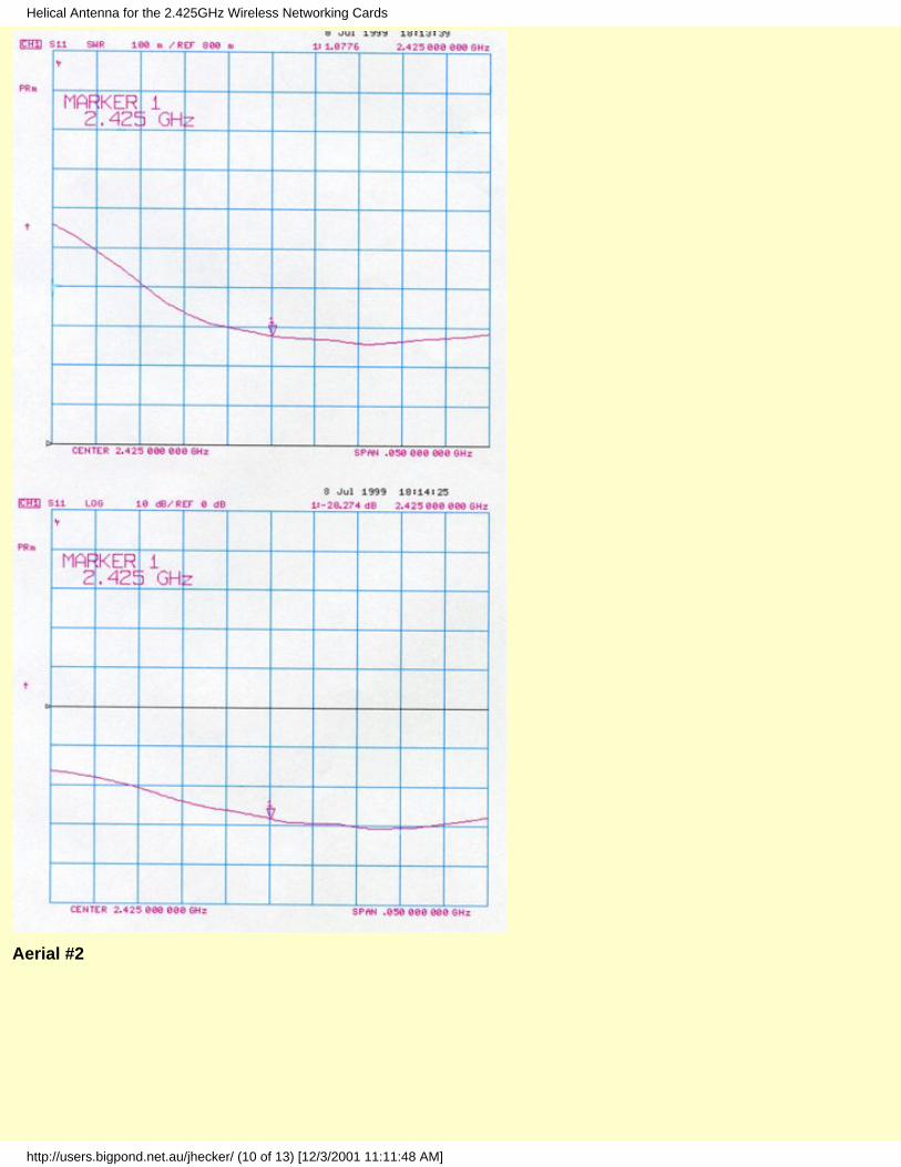
Aerial #2
Helical Antenna for the 2.425GHz Wireless Networking Cards
http://users.bigpond.net.au/jhecker/ (10 of 13) [12/3/2001 11:11:48 AM]
Beam Patterns
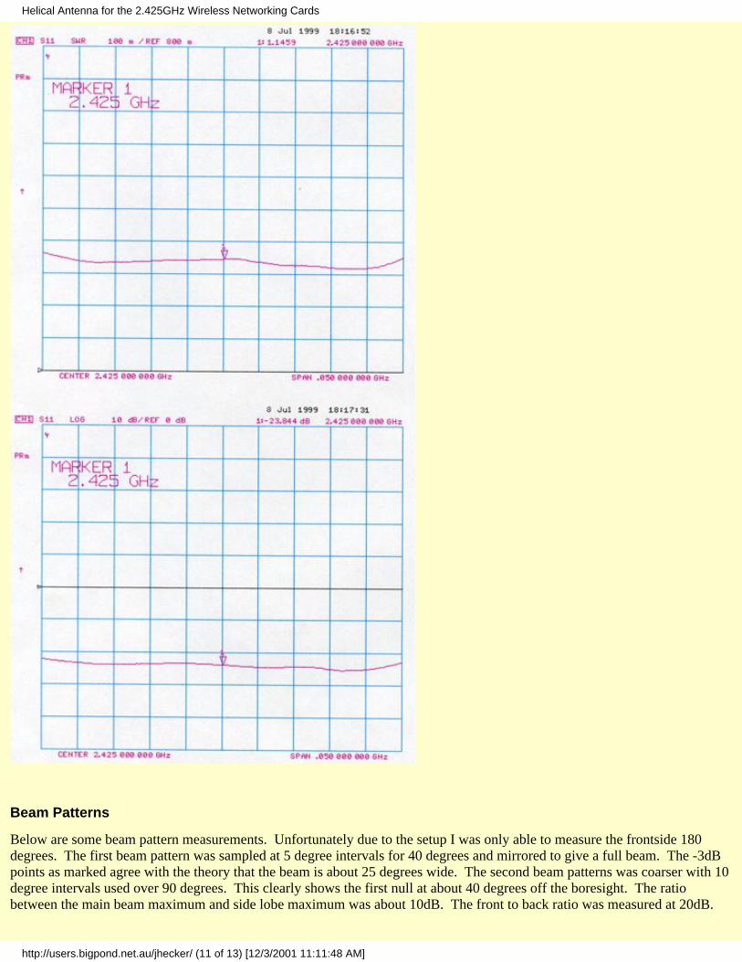
Below are some beam pattern measurements. Unfortunately due to the setup I was only able to measure the frontside 180degrees. The first beam pattern was sampled at 5 degree intervals for 40 degrees and mirrored to give a full beam. The -3dBpoints as marked agree with the theory that the beam is about 25 degrees wide. The second beam patterns was coarser with 10degree intervals used over 90 degrees. This clearly shows the first null at about 40 degrees off the boresight. The ratiobetween the main beam maximum and side lobe maximum was about 10dB. The front to back ratio was measured at 20dB.
Helical Antenna for the 2.425GHz Wireless Networking Cards
http://users.bigpond.net.au/jhecker/ (11 of 13) [12/3/2001 11:11:48 AM]
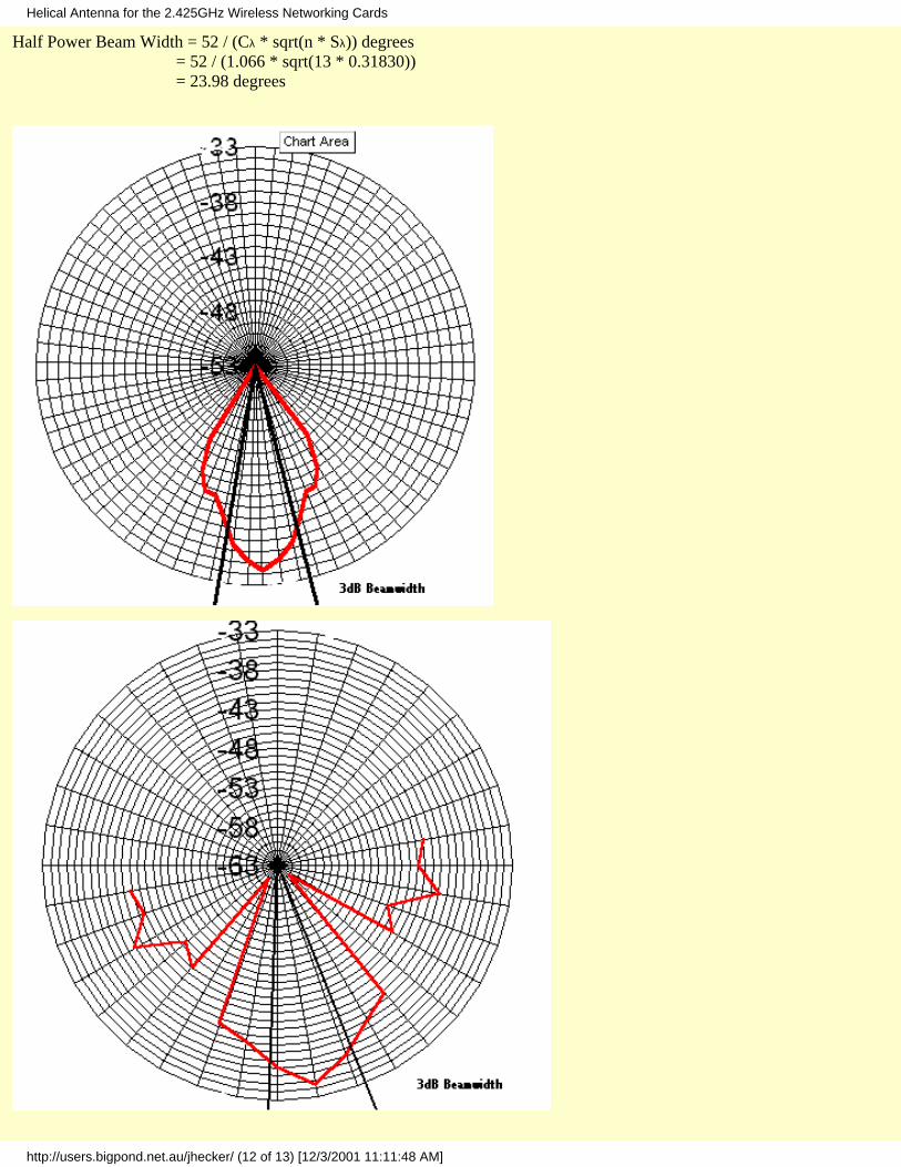
Half Power Beam Width = 52 / (Cλ * sqrt(n * Sλ)) degrees = 52 / (1.066 * sqrt(13 * 0.31830)) = 23.98 degrees
Helical Antenna for the 2.425GHz Wireless Networking Cards
http://users.bigpond.net.au/jhecker/ (12 of 13) [12/3/2001 11:11:48 AM]

(C)opyright 1999-2001 Jason Hecker [email protected]: 24 March 2001
Helical Antenna for the 2.425GHz Wireless Networking Cards
http://users.bigpond.net.au/jhecker/ (13 of 13) [12/3/2001 11:11:48 AM]

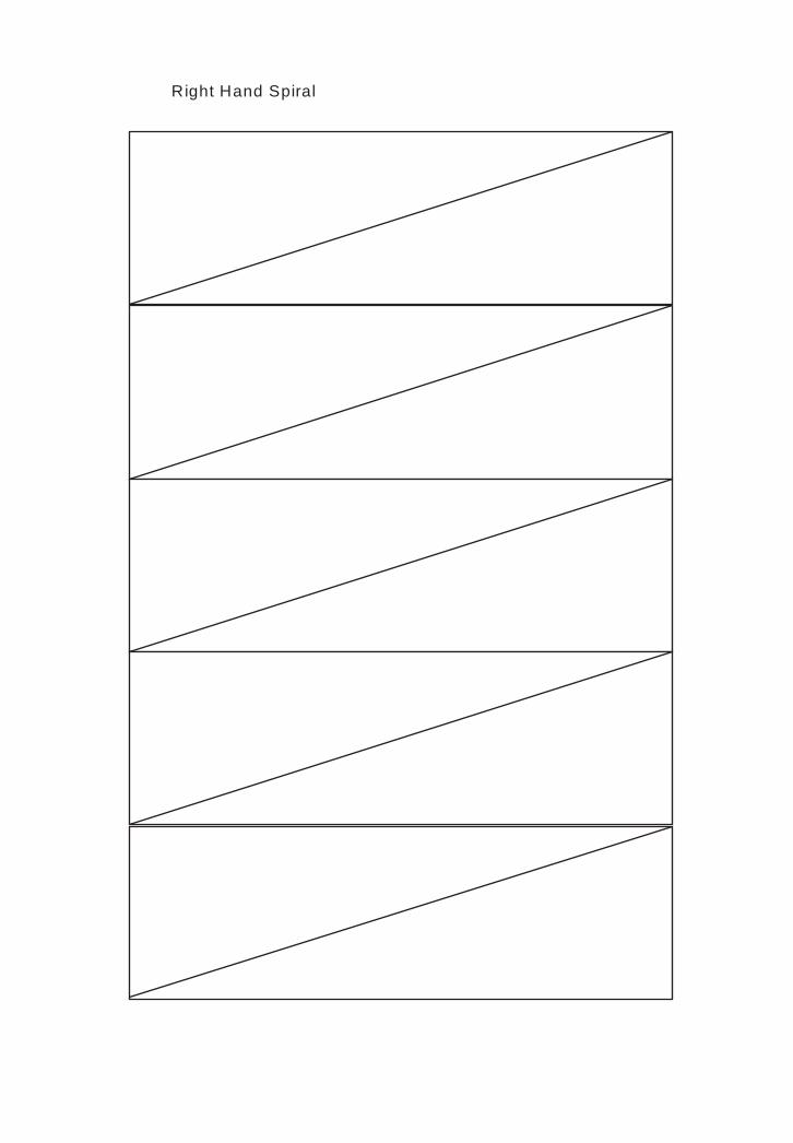
Right Hand Spiral
Left Hand Spiral
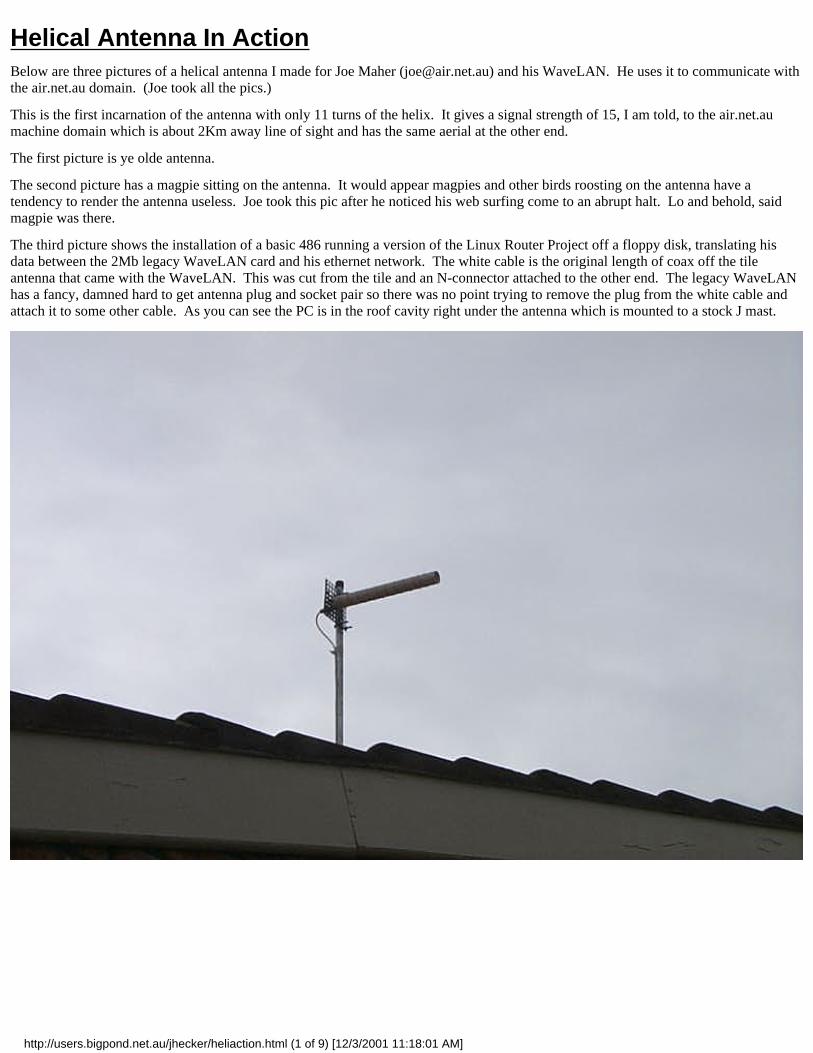
Helical Antenna In ActionBelow are three pictures of a helical antenna I made for Joe Maher ([email protected]) and his WaveLAN. He uses it to communicate withthe air.net.au domain. (Joe took all the pics.)
This is the first incarnation of the antenna with only 11 turns of the helix. It gives a signal strength of 15, I am told, to the air.net.aumachine domain which is about 2Km away line of sight and has the same aerial at the other end.
The first picture is ye olde antenna.
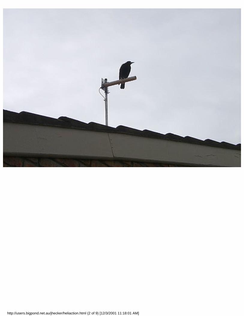
The second picture has a magpie sitting on the antenna. It would appear magpies and other birds roosting on the antenna have atendency to render the antenna useless. Joe took this pic after he noticed his web surfing come to an abrupt halt. Lo and behold, saidmagpie was there.
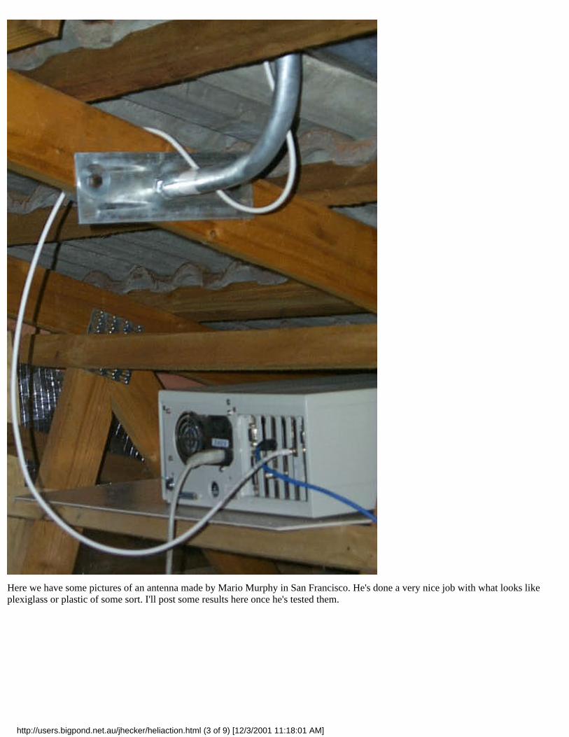
The third picture shows the installation of a basic 486 running a version of the Linux Router Project off a floppy disk, translating hisdata between the 2Mb legacy WaveLAN card and his ethernet network. The white cable is the original length of coax off the tileantenna that came with the WaveLAN. This was cut from the tile and an N-connector attached to the other end. The legacy WaveLANhas a fancy, damned hard to get antenna plug and socket pair so there was no point trying to remove the plug from the white cable andattach it to some other cable. As you can see the PC is in the roof cavity right under the antenna which is mounted to a stock J mast.
http://users.bigpond.net.au/jhecker/heliaction.html (1 of 9) [12/3/2001 11:18:01 AM]
http://users.bigpond.net.au/jhecker/heliaction.html (2 of 9) [12/3/2001 11:18:01 AM]
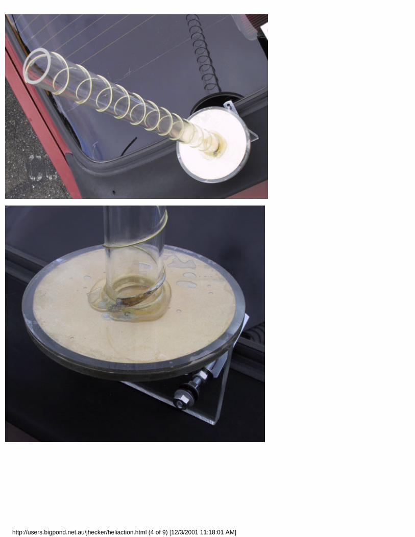
Here we have some pictures of an antenna made by Mario Murphy in San Francisco. He's done a very nice job with what looks likeplexiglass or plastic of some sort. I'll post some results here once he's tested them.
http://users.bigpond.net.au/jhecker/heliaction.html (3 of 9) [12/3/2001 11:18:01 AM]
http://users.bigpond.net.au/jhecker/heliaction.html (4 of 9) [12/3/2001 11:18:01 AM]
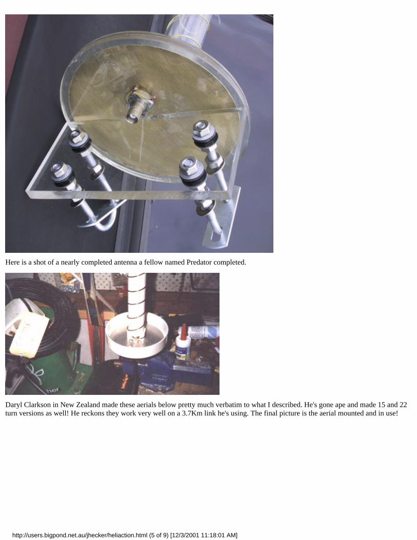
Here is a shot of a nearly completed antenna a fellow named Predator completed.
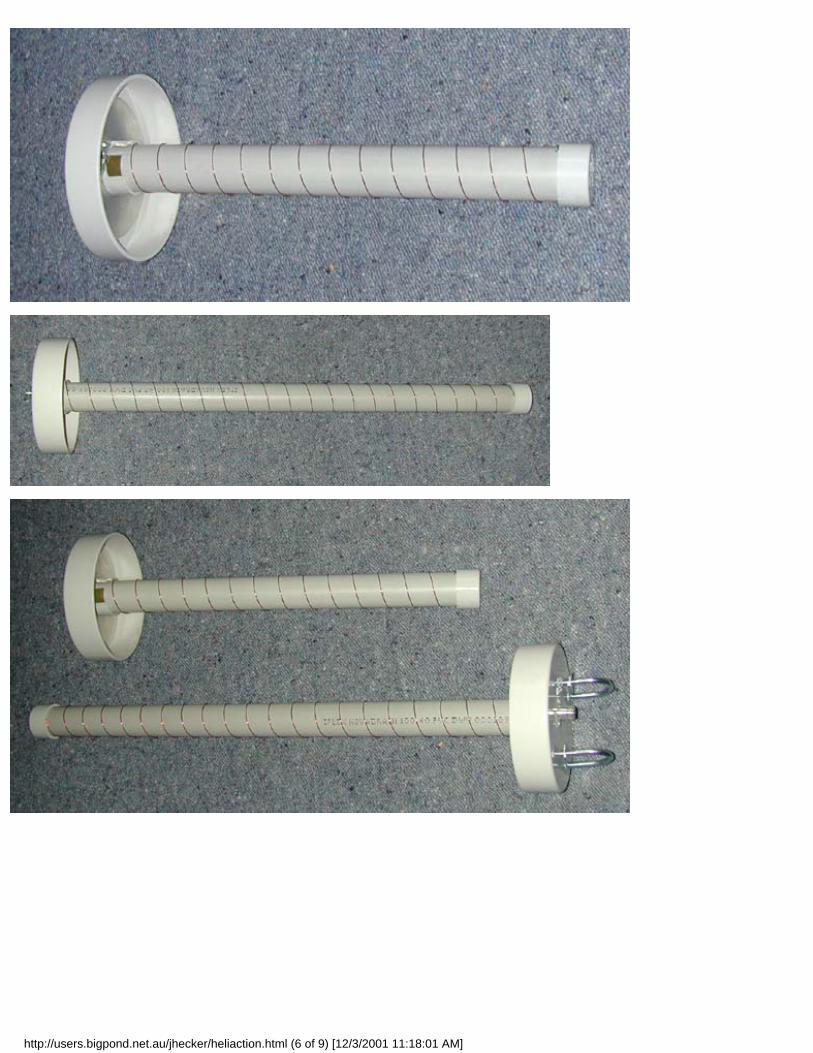
Daryl Clarkson in New Zealand made these aerials below pretty much verbatim to what I described. He's gone ape and made 15 and 22turn versions as well! He reckons they work very well on a 3.7Km link he's using. The final picture is the aerial mounted and in use!
http://users.bigpond.net.au/jhecker/heliaction.html (5 of 9) [12/3/2001 11:18:01 AM]
http://users.bigpond.net.au/jhecker/heliaction.html (6 of 9) [12/3/2001 11:18:01 AM]
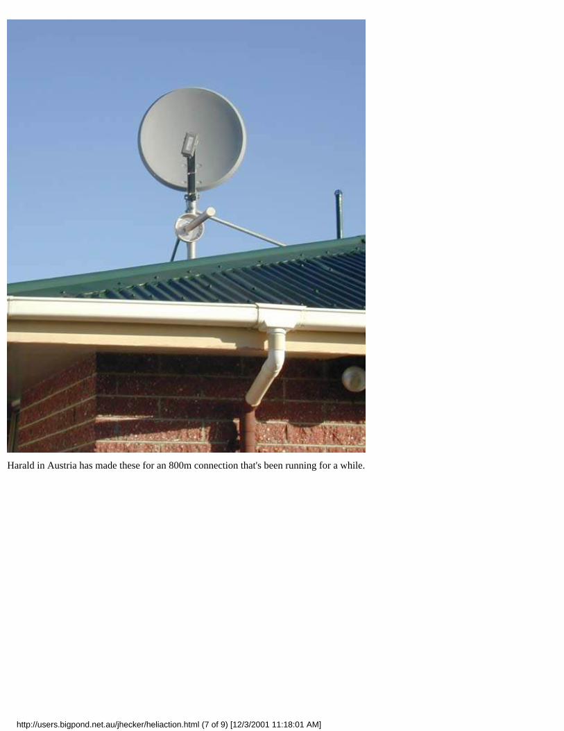
Harald in Austria has made these for an 800m connection that's been running for a while.
http://users.bigpond.net.au/jhecker/heliaction.html (7 of 9) [12/3/2001 11:18:01 AM]
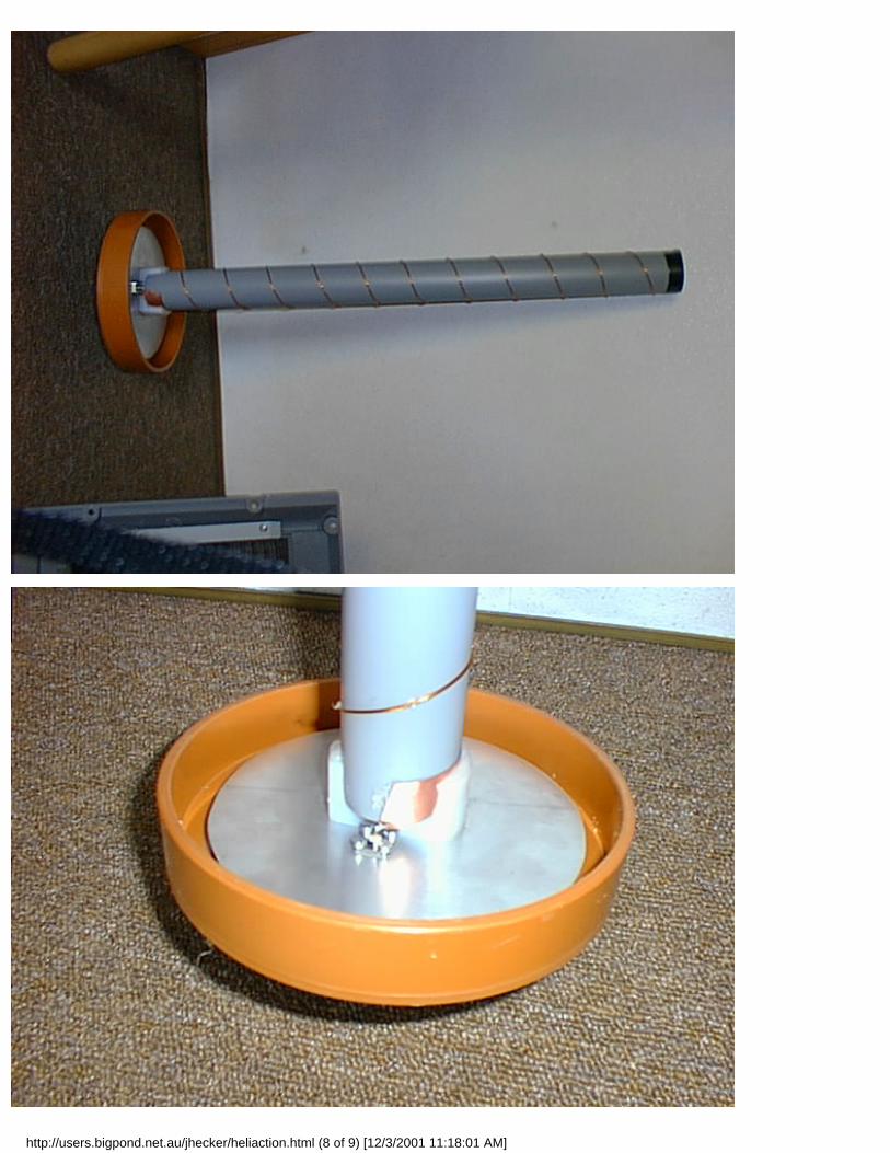
http://users.bigpond.net.au/jhecker/heliaction.html (8 of 9) [12/3/2001 11:18:01 AM]
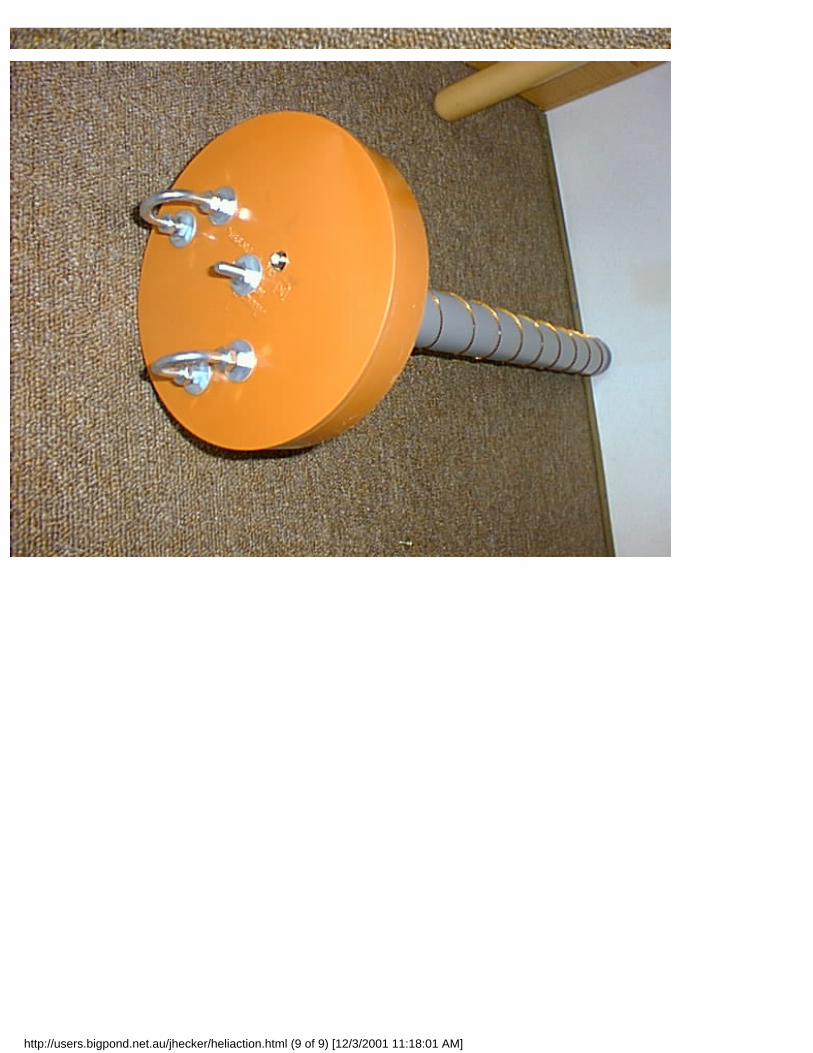
http://users.bigpond.net.au/jhecker/heliaction.html (9 of 9) [12/3/2001 11:18:01 AM]