heavy duty turning center - doosan machinetools
TRANSCRIPT

Heavy Duty Turning Center

02
Heavy Duty Turning Center

03
The Puma 600 / 700 / 800 XL / LY / XLY has a 5 meter workpiece length and Y axis capability,giving Doosan a unique place in the market. First, one setup completes extra long and large workpieces which require both turning and heavy duty milling. Second, extra rigid construction provides heavy duty machining. Third, high precision milling applications are possible using improved C axis performance and orthogonal Y axis capability.
One Set-UpPerformance
RigidStructure
HighPrecision
• The largest work envelope in it's class.
• 20% increased bed guideway span compared with current model.
• Integral hand-scraped box guideway construction on all slides.
• Addition of high resolution rotary scale for high precision C-axis control.
• X-Y interpolation - Easy and Fast milling operation.
Just single setup is enough for large and complex parts

04
PUMA 600 / 700 / 800 XL / LY / XLY
Model Investment Design Manpower Operation Tools
2 step
1 step
Turning Center
1 machine
Machining Center
1 machine
PUMA 700 XLY 1 machine
High EfficiencyPUMA 600 / 700 / 800 XL / LY / XLY are designed to maximise your productivity and increase profit.

05
Large Size WorkpieceOne setup can complete extra long and large complex parts requiring a variety of turning and milling operations.
Unit : mm ( inch )
ModelA*Bar
working
BMax. work
length
Max. turning dia.
Y-axis
PUMA 600XL / XLMPUMA 600XLY
ø 117( 4.6 )
5050( 198.8 )
900 ( 35.4 )750 ( 29.5 )
200 ( ±100 )( 7.9 ( ±3.9 ) )
PUMA 700XL / XLMPUMA 700XLY
ø 164( 6.5 )
5050( 198.8 )
900 ( 35.4 )750 ( 29.5 )
200 ( ±100 )( 7.9 ( ±3.9 ) )
PUMA 800XL / XLMPUMA 800XLY
ø 318**( 12.5** )
5050( 198.8 )
900 ( 35.4 )750 ( 29.5 )
200 ( ±100 )( 7.9 ( ±3.9 ) )
* : Workpiece diameter through drawtube.** : Maximum bar working in view of spindle bore without draw tube.
• PUMA 700XLY
Unit : mm ( inch )
ModelA*
Bar workingB
Max. work length
Max. turning dia.
Y-axis
PUMA 600L / LMPUMA 600LY
ø 117( 4.6 )
3200 ( 126.0 )3250 ( 128.0 )
900 ( 35.4 )750 ( 29.5 )
200 ( ±100 )( 7.9 ( ±3.9 ) )
PUMA 700L / LMPUMA 700LY
ø 164( 6.5 )
3200 ( 126.0 )3250 ( 128.0 )
900 ( 35.4 )750 ( 29.5 )
200 ( ±100 )( 7.9 ( ±3.9 ) )
PUMA 800L / LMPUMA 800LY
ø 318**( 12.5** )
3200 ( 126.0 )3250 ( 128.0 )
900 ( 35.4 )750 ( 29.5 )
200 ( ±100 )( 7.9 ( ±3.9 ) )
* : Workpiece diameter through drawtube.** : Maximum bar working in view of spindle bore without draw tube.
• PUMA 700LM
A
B
A
B

06
PUMA 600 / 700 / 800 XL / LY / XLY
The PUMA 600 / 700 / 800 XL / LY / XLY is a true 45 degree slant bed design. The bed is a one piece casting with both the saddle and tailstock guideways in the same plane to eliminate thermal distortion. The heavily ribbed torque tube design prevents twisting and deformation. Fine grain Meehanite processed cast iron is used because of its excellent damping characteristics. This ensures high rigidity with no deformation during heavy cutting. The slant angle allows for easy loading, changing and inspection of tools. All guideways are wide wrap-around rectangular type for un-surpassed long-term rigidity and accuracy. The guideways are widely spaced to ensure stability and fully protected. Each guide-way is induction hardened and precision ground. A fluroplastic resin, Rulon® 142, is bonded to the mating way surfaces, for its wear and friction characteristics and then hand scraped for a perfect fit and center height. Optional long bed enables extra-long shaft machining. Guide way span and Rib combination was redesigned to get better static and dynamic stiffness. Guide way span is 20 % larger than the current machine.
Rapid TraverseOutstanding rigidity for high feedratesScraping of Slideway Slant-design bed makes the
work go smoother, chipremoval much easier. Tough tubular construction stands up to the hardest cutting jobs.
Doosan Infracore precision machine tools are internationally known for their durability, rigidity and high accuracy. Only well proven and time tested manufacturing techniques canproduce machines of this quality.
High Efficiency

07
Main Spindle
PUMA 600 / 700 / 800 XL / LY / XLY
The 45kW ( 60.3Hp ) spindle motor provides power for heavy stock removal, greatly reducing the number of roughing passes required. The reliable digital AC spindle motor provides fast acceleration and is maintenance free. The preloaded spindle bearings are specifically calibrated to maintain the perfect balance of rigidity and speed. The geared headstock ensuresoptimal power throughout a wide speed range.
The headstock casting is made of Meehanite and ribbed on the outside to increase the surface area for better heat dissipation. The headstock and main spindle are manufactured in a temperature controlled environment then assembled and tested in our clean room. The heavy duty cartridge type spindle is supported by a double row of cylindrical roller bearings in the front and rear, with duplex angular thrust bearings in between. The cylindrical roller bearings feature a large contact surface which ensures the highest rigidity for heavy loads and superior surface finishes. All spindle bearings are permanently grease lubricated precision class P4.
Power is delivered to the spindle through a three ( PUMA 600 / 700 XL / XLM / LY / XLY ) or two ( PUMA 800 XL / XLM / LY / XLY ) speed geared head allowing stable spindle speeds change as well as powerful torque.
45( 60.3 )
30( 40.2 )20( 26.8 )
10( 13.4 )
45 ( 60.3 )
30 ( 40.2 )
20 ( 26.8 )
10 ( 13.4 )
2( 2.7 )20 100 2( 2.7 )20
45 ( 60.3 )
30 ( 40.2 )
20 ( 26.8 )
10 ( 13.4 )
2 ( 2.7 )20100 100 7501000 200010001500 3000
45 kW ( 60.3Hp ) 30min 45 kW ( 60.3Hp ) 30min 45 kW ( 60.3Hp ) 30min
T=918 N.m ( 6
77.5 ft-lbs )
T=1822 N.m ( 1
388.9 ft-lbs )
T=5416 N.m
( 3997.0 ft-lbs )
T=6605 N.m
( 4874.5 ft-lbs )
T=6605 N.m
( 4874.5 ft-lbs )
T=2222 N.m ( 1
639.8 ft-lbs )
T=2222 N.m ( 1
639.8 ft-lbs )
T=1120 N.m ( 8
26.6 ft-lbs )
1220 1800468
615923236
20779 310 170504
1001 1500384756193
65 254 170504
75619365 254
1000 1800 3000
Output : kW ( Hp )
Spindle speed ( r/min ) Spindle speed ( r/min ) Spindle speed ( r/min )
Output : kW ( Hp ) Output : kW ( Hp )
Main Spindle Drive Headstock and Spindle Construction
Geared Head
Main spindle power-torque diagram
Max. spindle speed
1800 r/min[ PUMA 600 XL / XLM / LY / XLY ]
1500 r/min[ PUMA 700 XL / XLM / LY / XLY ]
750 r/min[ PUMA 800 XL / XLM / LY / XLY ]
Motor ( 30 min )
45 kW ( 60.3 Hp )
PUMA 600 XL / XLM / LY / XLY
Max. spindle speed
1800 r/min
PUMA 700 XL / XLM / LY / XLY
Max. spindle speed
1500 r/min
PUMA 800 XL / XLM / LY / XLY
Max. spindle speed
750 r/min

08
PUMA 600 / 700 / 800 XL / LY / XLY
The large 12 station heavy duty turret features a large Curvic coupling diameter. This heavy duty design provides unsurpassed rigidity for heavy stock removal, fine surface finishes.
Heavy Duty Turret
Rotary tool spindle power-torque diagram
Preci-Flex Ready Rotary Tools
Radial BMT Turret
Index time ( 1-station swivel )
0.25 sNo. of tool station
12 ea• PUMA 600 / 700 / 800 XLM • PUMA 600 / 700 / 800 LY / XLY
10 ( 13.4 )
5 ( 6.7 )
1 ( 1.3 )100 750 1000 3000
11 kW ( 14.8 Hp ) 30min
T=140 N.m ( 1
03.3 ft-lbs )
Output : kW ( Hp )
Spindle speed ( r/min )
Collet application Preci-flex adapterapplication
Preci-Flex ready rotary tool holders are available on the milling versions. Preci-Flex is a tooling system utilizes the existing ER collet taper in the rotary holders. The spindle face is precision ground relative to the taper and there are four drilled and tapped holders in this face. The Preci-Flex adapters locate on both the taper and the spindle face for maximum rigidity.
Angular milling head
Straight milling head
Tool Holder DI holder base
PUMA 600 / 700 / 800 XL series
Tool Holder BMT 85P Max. Speed 3000 r/min Motor 11 / 7.5 r/min( 14.8 / 10.1 Hp )
PUMA 600 / 700 / 800 XLM / LY / XLY series
PUMA 600 / 700 / 800 XL / XLM / LY / XLY
Spindle motor
11 kW ( 14.8Hp ) / 30 min
Turret
The turret for rotary tool head features BMT style tooling in which the tool holders are mounted directly to the turret’s periphery using 4 large bolts.
This type of mounting system allows an extremely high degree of rigidity

09
Live Center Tail stock
Dead Center
Axis Drives
To get Y-axis movement, additional column way is used to move rotary tool across the face of the spindle.
In order to increase its rigidity, Tail stock was engineered more simply than current model. Quill travel is 200 mm ( 7.9 inch ).
Y-Axis Capability
Programmable Tailstock
Axis Drive Construction
The Y-axis way is placed under the carriage / cross slide, on which the turret is mounted . In the Y-axis plane, tools can move in a plus or minus direction perpendicular to the Z-axis and spindle center line. Viewed from the operator's perspective, this Y-axis motion is toward or away from the door of the machine while X-axis motion is floor to ceiling.
Each axis is powered by a maintenance free digital AC servo motor. These high torque drive motors are connected to the ball screws without intermediate gears for quiet and responsive slide movement with virtually no backlash.
Unit Previous PUMA 700XLY
Quill Thrust kN 32 42
Quill diameter mm ( inch ) 160 ( 6.3 ) 160 ( 6.3 )
Quill bore taper - MT#6 MT#6
Quill travel mm ( inch ) 160 ( 6.3 ) 200 ( 7.9 )
X-axis
400 mm ( 15.7 inch )
Y-axis
200 ( ± 100 ) mm ( 7.9 inch )
+ 100 mm( 3.9 inch )
- 100 mm( 3.9 inch )
std.
• PUMA 600 / 700 / 800 XL

10
Accuracy
C-axis index Precision X-Y simultaneous Precision
Thread Milling Function
C축 index
Rotary Scale Positioning Repeatability
PUMA 700XLY 9" 5"
PUMA 700XLM 8" 4"
Cutting Condition
Speed 1200 r/min
Feed 25 mm/min
Depth 0.5 mm
Tool ø 16 mm End mill* Carbon steel ( SM45C )
Cutting Condition
Speed 1500 r/min
Feed 260 mm/min
Depth 30 mm
Tool ø 20 mm Mill Thread* Carbon steel ( SM45C )
Cutting Hole PCD ø 350 mm( 13.8 inch )
Position 0.036 mm( 0.00141 inch )
Cutting Condition
Speed 1600 r/min
Feed 200 mm/min
Depth 0.5 mm
Tool ø 10 mm End mill* Carbon steel ( SM45C )
Roundness 0.029 mm( 0.0011 inch )
Roundness 0.030 mm( 0.0012 inch )
Squareness 0.010 mm( 0.0004 inch )
Squareness 0.015 mm( 0.0006 inch )
Straightness 0.004 mm( 0.0002 inch )
Straightness 0.005 mm( 0.0002 inch )
Parallelism 0.010 mm( 0.0004 inch )
Parallelism 0.010 mm( 0.0004 inch )
Y-Z simultaneous Precision
C-X Polar Interpolation ( Eccentric circle )
Cutting Condition
Speed 1600 r/min
Feed 260 mm/min
Depth 0.5 mm
Tool ø 10 mm End mill* Carbon steel ( SM45C )
Roundness ( ø 200 mm )
0.025 mm ( 0.001 inch )
Cutting sample M55 x P2.0 ThreadCutting method C-X Polar Coordinate
X-Y / Y-Z Helical Interpolation
Test results
Thread Gage Check

11
High Performance
• The results indicated in this catalogue are provided as example. They may not be obtained due to differences in cutting conditions and environmental conditions during measurement.
• Turing results are obtained in the condition of standard motor.
End mill ( Low Speed )Material SM45C
Cutting Tool ø 32 ( HSS )
Cutting Condition Speed m/min 30
Feed mm/min 90
Chip Removal rate cm3/min 105
Helical End MillingMaterial SM45C
Cutting Tool ø 25 ( Carbide )
Cutting Condition Speed m/min 240
Feed mm/min 800
Chip Removal rate cm3/min 100
TappingMaterial SM45C
Cutting Tool M33 x P3.5
Cutting Condition Speed m/min 15
Feed mm/rev 3.5
Spindle Load 125 %
Material SM45C
Cutting Tool ø 25 ( Carbide )
Cutting Condition Speed m/min 220
Feed mm/min 1000
Chip Removal rate cm3/min 175
End mill ( High Speed )
Material SM45CCutting Condition Speed m/min 230
Feed mm/rev 0.6Dia mm ø 380Depth mm 10
Chip Removal rate cm3/min 1418
O.D turning
Material SM45C
Cutting Tool ø 30 U-Drill
Cutting Condition Speed r/min 2000
Feed mm/rev 0.12
Chip Removal rate cm3/min 171
U-Drill ( Rotary Drilling )
More powerful revolving motor is adapted to improve the productivity.
12
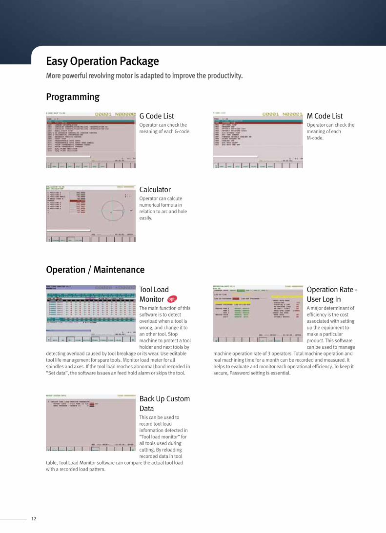
Easy Operation PackageMore powerful revolving motor is adapted to improve the productivity.
opt.
Programming
Operation / Maintenance
G Code ListOperator can check the meaning of each G-code.
CalculatorOperator can calcute numerical formula in relation to arc and hole easily.
Back Up Custom DataThis can be used to record tool load information detected in “Tool load monitor” for all tools used during cutting. By reloading recorded data in tool
table, Tool Load Monitor software can compare the actual tool load with a recorded load pattern.
Operation Rate - User Log InA major determinant of efficiency is the cost associated with setting up the equipment to make a particular product. This software can be used to manage
machine operation rate of 3 operators. Total machine operation and real machining time for a month can be recorded and measured. It helps to evaluate and monitor each operational efficiency. To keep it secure, Password setting is essential.
M Code ListOperator can check the meaning of each M-code.
Tool Load MonitorThe main function of this software is to detect overload when a tool is wrong, and change it to an other tool. Stop machine to protect a tool holder and next tools by
detecting overload caused by tool breakage or its wear. Use editable tool life management for spare tools. Monitor load meter for all spindles and axes. If the tool load reaches abnormal band recorded in “Set data”, the software issues an feed hold alarm or skips the tool.

13
Easy Guide iOperation Guidance, which supports entire operations on an all-in-one screen for daily machining including creating a program on the machine.
Programming time can be reduced
Cycle machining menus for both of lathe machining and milling are available
• Realistic drawing of both turning and milling with 3-D solid models are available.
• Milling on a slanted surface can be simulated.
• Cutter mark according to a tool tip shape can be expressed.
• Tool path drawing is available
The tool database is constructed by adding Manual Guide i data to conventional CNC tool data.
• Tool Offset Data( Standard CNC tool data )
• Tool Type( General, Threading, Grooving, Drilling, Tapping, End Mill, etc. )
• Tool Setting( OD, ID, Right, Left, etc. )
• Tool Shape Data( Tool Nose Radius, Cutting Angle, Grooving width, Grooving length, Threading Angle, etc. )
• Drilling
• Bar roughing ( including preformed work-piece )
• Bar finishing
• Threading ( General purpose thread, metric, etc. )
• Grooving ( Standard, Trapezoidal )
Realistic machining simulation
Tool data management function
Cycle for lathe machining
• Uses one display screen to perform all operations including programming, checking by animation, and real machining.
• User-Friendly Operation :Soft key selection of comprehensive cycle library
• Easy programmingBased on ISO-code program format, complex machining motions can be created easily by this menu format.
• Machine status windowMachine status such as actual position, feedrate and load meter are always displayed.
• Realistic machining simulation3-D solid model machining simulation is available.
• Intuitive menu selectingMenu can be selected easily and intuitively by soft-keys with icons.
Reducing time for checking machining program
Tool Path Drawing Screen Animated Drawing Screen
Example of Tool Data Screen
Example of Lathe Machining Cycle
• Automatically referenced for animation
• Automatically referenced when Cycle Command is executed
14
195( 7.7 )
5100 ( 200.8 ) : Z-axis travel
6( 0.2 )
200( 7.9 )
4885 ( 192.3 )
5295 ( 208.5 )
420
( 16.
5 )20 ( 0
.8 )
440 (
17.3
)30
( 1.2
)
470 (
18.5
) : X-
axis
trave
l
ø160
( 6.3
)
ø 610
( 24 )
34( 1.3 )
149( 5.9 )
73( 2.9 )
800 (
31.5
)
4900 ( 192.9 )
64( 2.5 )
200 ( 7.9 )
55( 2.2 )
5094 ( 200.6 )
200 ( 7.9 )
5295 ( 208.5 )
189( 7.4 )
5100 ( 200.8 ) : Z-axis travel 6( 0.2 )
470 (
18.5
) : X-
axis
trave
l
ø160
( 6.3
)
80 ( 3.1
)5 ( 0.2
)
30( 1
.2 )
45( 1.8 )
30 ( 1.2 )
61( 2.4 )
ø 610
( 24 )
800 (
31.5
)
5289 ( 208.2 )
5295 ( 208.5 )
20 ( 0.8
)42
0( 1
6.5 )
30 ( 1.2
)
34(1.3 )
149( 5.9 )
73( 2.9 )
64( 2.5 )
187( 7.4 )
5100 ( 200.8 ) : Z-axis travel8 ( 0.3 )
50 ( 2.0
)
ø160
( 6.3
)
30 ( 1
.2 )
15 ( 0.6
)20 ( 0.8
)
450
( 17.
7 )20 ( 0.8
)
30 ( 1
.2 )
420 (
16.5
)47
0 (18
.5) :
X-ax
is tra
vel
200 ( 7.9 ) 4885 ( 192.3 )62
( 21.4)17
( 0.7 )63
( 2.5 )
291 200.6 )( 5905( 7.6 )5287 ( 208.1 )
ø 610
( 24 )
800 (
31.5
)30
0( 1
1.8 )
5295 ( 208.5 )
4998 ( 196.8 )
34( 1.3 )
149( 5.9 )
73 ( 2.9 )
64( 2.5 )
295( 11.6 )
5100 ( 200.8 ) : Z-axis travel
70 ( 2.8 )
58( 2.3 )
37( 1.5 )
20( 0.8 )
15 ( 0.6
)15 ( 0
.6 )
430
( 16.
9 )40 ( 1
.6 )
470 (
18.5
) : X-a
xis tra
vel
34 ( 1.3 )100
( 3.9
)105
( 4.1
)
ø 610
( 24 )
149 73
65 ( 2.6 )
800 (
31.5
)
98 39
5125 ( 201.8 ) 200 ( 7.9 )
5055 ( 199.0 )
165( 6.5 )
5100 ( 200.8 ) : Z-axis travel 8( 0.3 )
52( 2.0 )
85 ( 3.3
)
ø160
( 6.3
)
35 (1.4
)
5 ( 0.
2 )
20 (0.8
)
450
( 17.
7 )20 ( 0
.8 )
20 ( 0.8
)43
0( 1
6.9 )
470 (
18.5
) : X-
axis
trave
l
4885 ( 192.3 )60
( 2.4 )35
( 1.4 )85 ( 3.3 )
5125 ( 201.8 ) 140( 5.5 )5265 ( 207.3 )
ø 610
( 24 )
800 (
31.5
)
5050 ( 198.8 )
5325 ( 209.6 )
4955 ( 195.1 )
64( 2.5 )
149( 5.9 )
73( 2.9 )
98( 3.9 ) ( 5.9 )( 2.9 )( 3.9 ) ( 5.9 )( 2.9 ) ( 1.5 )( 3.9 )
170( 6.7 )
5100 ( 200.8 ) : Z-axis travel 55 ( 2.2 )
85 ( 3.3
)
470 (
18.5
) : X-a
xis tra
vel
ø160
( 6.3
)
90 ( 3.5
)5 (
0.2 )
20 ( 0.8
)
40( 1.6 )
55( 2.2 )
80( 3.1 )
ø 610
( 24 )
800 (
31.5
)
5270 ( 207.5 )
64( 2.5 )
450 (
17.7
)20 ( 0
.8 )
20 ( 0.8
)43
0( 1
6.9 )
149 7398
155( 6.1 )
5100 ( 200.8 ) : Z-axis travel 70( 2.8 )
45( 1.8 )
50( 2.0 )
95 ( 3.7 )
90 ( 3
.5 )
5( 0
.2 )
100 ( 3.9 )
ø32 (
1.3 )85 ( 3
.3 )
450
( 17.
7 )20 ( 0
.8 )
470 (
18.5
) : X-ax
is trav
el
ø160
( 6.3
)80
0 ( 31
.5 )
ø 610
( 24 )
5000 ( 196.9 )
5094 ( 200.6 )149( 5.9 )
73( 2.9 )
98( 3.9 )
PUMA 600 / 700 / 800 XL
Stroke Diagram OD Tool Holder
ID Tool holder
195( 7.7 )
5100 ( 200.8 ) : Z-axis travel
6( 0.2 )
200( 7.9 )
4885 ( 192.3 )
5295 ( 208.5 )
420
( 16.
5 )20 ( 0
.8 )
440 (
17.3
)30
( 1.2
)
470 (
18.5
) : X-
axis
trave
l
ø160
( 6.3
)
ø 610
( 24 )
34( 1.3 )
149( 5.9 )
73( 2.9 )
800 (
31.5
)
4900 ( 192.9 )
64( 2.5 )
200 ( 7.9 )
55( 2.2 )
5094 ( 200.6 )
200 ( 7.9 )
5295 ( 208.5 )
189( 7.4 )
5100 ( 200.8 ) : Z-axis travel 6( 0.2 )
470 (
18.5
) : X-
axis
trave
l
ø160
( 6.3
)
80 ( 3.1
)5 ( 0.2
)
30( 1
.2 )
45( 1.8 )
30 ( 1.2 )
61( 2.4 )
ø 610
( 24 )
800 (
31.5
)
5289 ( 208.2 )
5295 ( 208.5 )
20 ( 0.8
)42
0( 1
6.5 )
30 ( 1.2
)
34(1.3 )
149( 5.9 )
73( 2.9 )
64( 2.5 )
187( 7.4 )
5100 ( 200.8 ) : Z-axis travel8 ( 0.3 )
50 ( 2.0
)
ø160
( 6.3
)
30 ( 1
.2 )
15 ( 0.6
)20 ( 0.8
)
450
( 17.
7 )20 ( 0.8
)
30 ( 1
.2 )
420 (
16.5
)47
0 (18
.5) :
X-ax
is tra
vel
200 ( 7.9 ) 4885 ( 192.3 )62
( 21.4)17
( 0.7 )63
( 2.5 )
291 200.6 )( 5905( 7.6 )5287 ( 208.1 )
ø 610
( 24 )
800 (
31.5
)30
0( 1
1.8 )
5295 ( 208.5 )
4998 ( 196.8 )
34( 1.3 )
149( 5.9 )
73 ( 2.9 )
64( 2.5 )
295( 11.6 )
5100 ( 200.8 ) : Z-axis travel
70 ( 2.8 )
58( 2.3 )
37( 1.5 )
20( 0.8 )
15 ( 0.6
)15 ( 0
.6 )
430
( 16.
9 )40 ( 1
.6 )
470 (
18.5
) : X-a
xis tra
vel
34 ( 1.3 )100
( 3.9
)105
( 4.1
)
ø 610
( 24 )
149 73
65 ( 2.6 )
800 (
31.5
)
98 39
5125 ( 201.8 ) 200 ( 7.9 )
5055 ( 199.0 )
165( 6.5 )
5100 ( 200.8 ) : Z-axis travel 8( 0.3 )
52( 2.0 )
85 ( 3.3
)
ø160
( 6.3
)
35 (1.4
)
5 ( 0.
2 )
20 (0.8
)
450
( 17.
7 )20 ( 0
.8 )
20 ( 0.8
)43
0( 1
6.9 )
470 (
18.5
) : X-
axis
trave
l
4885 ( 192.3 )60
( 2.4 )35
( 1.4 )85 ( 3.3 )
5125 ( 201.8 ) 140( 5.5 )5265 ( 207.3 )
ø 610
( 24 )
800 (
31.5
)
5050 ( 198.8 )
5325 ( 209.6 )
4955 ( 195.1 )
64( 2.5 )
149( 5.9 )
73( 2.9 )
98( 3.9 ) ( 5.9 )( 2.9 )( 3.9 ) ( 5.9 )( 2.9 ) ( 1.5 )( 3.9 )
170( 6.7 )
5100 ( 200.8 ) : Z-axis travel 55 ( 2.2 )85 ( 3
.3 )
470 (
18.5
) : X-a
xis tra
vel
ø160
( 6.3
)
90 ( 3.5
)5 (
0.2 )
20 ( 0.8
)
40( 1.6 )
55( 2.2 )
80( 3.1 )
ø 610
( 24 )
800 (
31.5
)
5270 ( 207.5 )
64( 2.5 )
450 (
17.7
)20 ( 0
.8 )
20 ( 0.8
)43
0( 1
6.9 )
149 7398
155( 6.1 )
5100 ( 200.8 ) : Z-axis travel 70( 2.8 )
45( 1.8 )
50( 2.0 )
95 ( 3.7 )
90 ( 3
.5 )
5( 0
.2 )
100 ( 3.9 )
ø32 (
1.3 )85 ( 3
.3 )
450
( 17.
7 )20 ( 0
.8 )
470 (
18.5
) : X-ax
is trav
el
ø160
( 6.3
)80
0 ( 31
.5 )
ø 610
( 24 )
5000 ( 196.9 )
5094 ( 200.6 )149( 5.9 )
73( 2.9 )
98( 3.9 )
195( 7.7 )
5100 ( 200.8 ) : Z-axis travel
6( 0.2 )
200( 7.9 )
4885 ( 192.3 )
5295 ( 208.5 )
420
( 16.
5 )20 ( 0
.8 )
440 (
17.3
)30
( 1.2
)
470 (
18.5
) : X-
axis
trave
l
ø160
( 6.3
)
ø 610
( 24 )
34( 1.3 )
149( 5.9 )
73( 2.9 )
800 (
31.5
)
4900 ( 192.9 )
64( 2.5 )
200 ( 7.9 )
55( 2.2 )
5094 ( 200.6 )
200 ( 7.9 )
5295 ( 208.5 )
189( 7.4 )
5100 ( 200.8 ) : Z-axis travel 6( 0.2 )
470 (
18.5
) : X-
axis
trave
l
ø160
( 6.3
)
80 ( 3.1
)5 ( 0.2
)
30( 1
.2 )
45( 1.8 )
30 ( 1.2 )
61( 2.4 )
ø 610
( 24 )
800 (
31.5
)
5289 ( 208.2 )
5295 ( 208.5 )
20 ( 0.8
)42
0( 1
6.5 )
30 ( 1.2
)
34(1.3 )
149( 5.9 )
73( 2.9 )
64( 2.5 )
187( 7.4 )
5100 ( 200.8 ) : Z-axis travel8 ( 0.3 )
50 ( 2.0
)
ø160
( 6.3
)
30 ( 1
.2 )
15 ( 0.6
)20 ( 0.8
)
450
( 17.
7 )20 ( 0.8
)
30 ( 1
.2 )
420 (
16.5
)47
0 (18
.5) :
X-ax
is tra
vel
200 ( 7.9 ) 4885 ( 192.3 )62
( 21.4)17
( 0.7 )63
( 2.5 )
291 200.6 )( 5905( 7.6 )5287 ( 208.1 )
ø 610
( 24 )
800 (
31.5
)30
0( 1
1.8 )
5295 ( 208.5 )
4998 ( 196.8 )
34( 1.3 )
149( 5.9 )
73 ( 2.9 )
64( 2.5 )
295( 11.6 )
5100 ( 200.8 ) : Z-axis travel
70 ( 2.8 )
58( 2.3 )
37( 1.5 )
20( 0.8 )
15 ( 0.6
)15 ( 0
.6 )
430
( 16.
9 )40 ( 1
.6 )
470 (
18.5
) : X-a
xis tra
vel
34 ( 1.3 )100
( 3.9
)105
( 4.1
)
ø 610
( 24 )
149 73
65 ( 2.6 )
800 (
31.5
)
98 39
5125 ( 201.8 ) 200 ( 7.9 )
5055 ( 199.0 )
165( 6.5 )
5100 ( 200.8 ) : Z-axis travel 8( 0.3 )
52( 2.0 )
85 ( 3.3
)
ø160
( 6.3
)
35 (1.4
)
5 ( 0.
2 )
20 (0.8
)
450
( 17.
7 )20 ( 0
.8 )
20 ( 0.8
)43
0( 1
6.9 )
470 (
1 8.5
) : X-
axis
trave
l
4885 ( 192.3 )60
( 2.4 )35
( 1.4 )85 ( 3.3 )
5125 ( 201.8 ) 140( 5.5 )5265 ( 207.3 )
ø 610
( 24 )
800 (
31.5
)
5050 ( 198.8 )
5325 ( 209.6 )
4955 ( 195.1 )
64( 2.5 )
149( 5.9 )
73( 2.9 )
98( 3.9 ) ( 5.9 )( 2.9 )( 3.9 ) ( 5.9 )( 2.9 ) ( 1.5 )( 3.9 )
170( 6.7 )
5100 ( 200.8 ) : Z-axis travel 55 ( 2.2 )
85 ( 3.3
)
470 (
18.5
) : X-a
xis tra
vel
ø160
( 6.3
)
90 ( 3.5
)5 (
0.2 )
20 ( 0.8
)
40( 1.6 )
55( 2.2 )
80( 3.1 )
ø 610
( 24 )
800 (
31.5
)
5270 ( 207.5 )
64( 2.5 )
450 (
17.7
)20 ( 0
.8 )
20 ( 0.8
)43
0( 1
6.9 )
149 7398
155( 6.1 )
5100 ( 200.8 ) : Z-axis travel 70( 2.8 )
45( 1.8 )
50( 2.0 )
95 ( 3.7 )
90 ( 3
.5 )
5( 0
.2 )
100 ( 3.9 )
ø32 (
1.3 )85 ( 3
.3 )
450
( 17.
7 )20 ( 0
.8 )
470 (
18.5
) : X-ax
is trav
el
ø160
( 6.3
)80
0 ( 31
.5 )
ø 610
( 24 )
5000 ( 196.9 )
5094 ( 200.6 )149( 5.9 )
73( 2.9 )
98( 3.9 )
195( 7.7 )
5100 ( 200.8 ) : Z-axis travel
6( 0.2 )
200( 7.9 )
4885 ( 192.3 )
5295 ( 208.5 )42
0( 1
6.5 )
20 ( 0.8
)
440 (
17.3
)30
( 1.2
)
470 (
18.5
) : X-
axis
trave
l
ø160
( 6.3
)
ø 610
( 24 )
34( 1.3 )
149( 5.9 )
73( 2.9 )
800 (
31.5
)
4900 ( 192.9 )
64( 2.5 )
200 ( 7.9 )
55( 2.2 )
5094 ( 200.6 )
200 ( 7.9 )
5295 ( 208.5 )
189( 7.4 )
5100 ( 200.8 ) : Z-axis travel 6( 0.2 )
470 (
18.5
) : X-
axis
trave
l
ø160
( 6.3
)
80 ( 3.1
)5 ( 0.2
)
30( 1
.2 )
45( 1.8 )
30 ( 1.2 )
61( 2.4 )
ø 610
( 24 )
800 (
31.5
)
5289 ( 208.2 )
5295 ( 208.5 )
20 ( 0.8
)42
0( 1
6.5 )
30 ( 1.2
)
34(1.3 )
149( 5.9 )
73( 2.9 )
64( 2.5 )
187( 7.4 )
5100 ( 200.8 ) : Z-axis travel8 ( 0.3 )
50 ( 2.0
)
ø160
( 6.3
)
30 ( 1
.2 )
15 ( 0.6
)20 ( 0.8
)
450
( 17.
7 )20 ( 0.8
)
30 ( 1
.2 )
420 (
16.5
)47
0 (18
.5) :
X-ax
is tra
vel
200 ( 7.9 ) 4885 ( 192.3 )62
( 21.4)17
( 0.7 )63
( 2.5 )
291 200.6 )( 5905( 7.6 )5287 ( 208.1 )
ø 610
( 24 )
800 (
31.5
)30
0( 1
1.8 )
5295 ( 208.5 )
4998 ( 196.8 )
34( 1.3 )
149( 5.9 )
73 ( 2.9 )
64( 2.5 )
295( 11.6 )
5100 ( 200.8 ) : Z-axis travel
70 ( 2.8 )
58( 2.3 )
37( 1.5 )
20( 0.8 )
15 ( 0.6
)15 ( 0
.6 )
430
( 16.
9 )40 ( 1
.6 )
470 (
18.5
) : X-a
xis tra
vel
34 ( 1.3 )100
( 3.9
)105
( 4.1
)
ø 610
( 24 )
149 73
65 ( 2.6 )
800 (
31.5
)
98 39
5125 ( 201.8 ) 200 ( 7.9 )
5055 ( 199.0 )
165( 6.5 )
5100 ( 200.8 ) : Z-axis travel 8( 0.3 )
52( 2.0 )
85 ( 3.3
)
ø160
( 6.3
)
35 (1.4
)
5 ( 0.
2 )
20 (0.8
)
450
( 17.
7 )20 ( 0
.8 )
20 ( 0.8
)43
0( 1
6.9 )
470 (
18.5
) : X-
axis
trave
l
4885 ( 192.3 )60
( 2.4 )35
( 1.4 )85 ( 3.3 )
5125 ( 201.8 ) 140( 5.5 )5265 ( 207.3 )
ø 610
( 24 )
800 (
31.5
)
5050 ( 198.8 )
5325 ( 209.6 )
4955 ( 195.1 )
64( 2.5 )
149( 5.9 )
73( 2.9 )
98( 3.9 ) ( 5.9 )( 2.9 )( 3.9 ) ( 5.9 )( 2.9 ) ( 1.5 )( 3.9 )
170( 6.7 )
5100 ( 200.8 ) : Z-axis travel 55 ( 2.2 )
85 ( 3.3
)
470 (
18.5
) : X-a
xis tra
vel
ø160
( 6.3
)
90 ( 3.5
)5 (
0.2 )
20 ( 0.8
)
40( 1.6 )
55( 2.2 )
80( 3.1 )
ø 610
( 24 )
800 (
31.5
)
5270 ( 207.5 )
64( 2.5 )
450 (
17.7
)20 ( 0
.8 )
20 ( 0.8
)43
0( 1
6.9 )
149 7398
155( 6.1 )
5100 ( 200.8 ) : Z-axis travel 70( 2.8 )
45( 1.8 )
50( 2.0 )
95 ( 3.7 )
90 ( 3
.5 )
5( 0
.2 )
100 ( 3.9 )
ø32 (
1.3 )85 ( 3
.3 )
450
( 17.
7 )20 ( 0
.8 )
470 (
18.5
) : X-ax
is trav
el
ø160
( 6.3
)80
0 ( 31
.5 )
ø 610
( 24 )
5000 ( 196.9 )
5094 ( 200.6 )149( 5.9 )
73( 2.9 )
98( 3.9 )
195( 7.7 )
5100 ( 200.8 ) : Z-axis travel
6( 0.2 )
200( 7.9 )
4885 ( 192.3 )
5295 ( 208.5 )
420
( 16.
5 )20 ( 0
.8 )
440 (
17.3
)30
( 1.2
)
470 (
18.5
) : X-
axis
trave
l
ø160
( 6.3
)
ø 610
( 24 )
34( 1.3 )
149( 5.9 )
73( 2.9 )
800 (
31.5
)
4900 ( 192.9 )
64( 2.5 )
200 ( 7.9 )
55( 2.2 )
5094 ( 200.6 )
200 ( 7.9 )
5295 ( 208.5 )
189( 7.4 )
5100 ( 200.8 ) : Z-axis travel 6( 0.2 )
470 (
18.5
) : X-
axis
trave
l
ø160
( 6.3
)
80 ( 3.1
)5 ( 0.2
)
30( 1
.2 )
45( 1.8 )
30 ( 1.2 )
61( 2.4 )
ø 610
( 24 )
800 (
31.5
)
5289 ( 208.2 )
5295 ( 208.5 )
20 ( 0.8
)42
0( 1
6.5 )
30 ( 1.2
)
34(1.3 )
149( 5.9 )
73( 2.9 )
64( 2.5 )
187( 7.4 )
5100 ( 200.8 ) : Z-axis travel8 ( 0.3 )
50 ( 2.0
)
ø160
( 6.3
)
30 ( 1
.2 )
15 ( 0.6
)20 ( 0.8
)
450
( 17.
7 )20 ( 0.8
)
30 ( 1
.2 )
420 (
16.5
)47
0 (18
.5) :
X-ax
is tra
vel
200 ( 7.9 ) 4885 ( 192.3 )62
( 21.4)17
( 0.7 )63
( 2.5 )
291 200.6 )( 5905( 7.6 )5287 ( 208.1 )
ø 610
( 24 )
800 (
31.5
)30
0( 1
1.8 )
5295 ( 208.5 )
4998 ( 196.8 )
34( 1.3 )
149( 5.9 )
73 ( 2.9 )
64( 2.5 )
295( 11.6 )
5100 ( 200.8 ) : Z-axis travel
70 ( 2.8 )
58( 2.3 )
37( 1.5 )
20( 0.8 )
15 ( 0.6
)15 ( 0
.6 )
430
( 16.
9 )40 ( 1
.6 )
470 (
18.5
) : X-a
xis tra
vel
34 ( 1.3 )100
( 3.9
)105
( 4.1
)
ø 610
( 24 )
149 73
65 ( 2.6 )
800 (
31.5
)
98 39
5125 ( 201.8 ) 200 ( 7.9 )
5055 ( 199.0 )
165( 6.5 )
5100 ( 200.8 ) : Z-axis travel 8( 0.3 )
52( 2.0 )
85 ( 3.3
)
ø160
( 6.3
)
35 (1.4
)
5 ( 0.
2 )
20 (0.8
)
450
( 17.
7 )20 ( 0
.8 )
20 ( 0.8
)43
0( 1
6.9 )
470 (
18.5
) : X-
axis
trave
l
4885 ( 192.3 )60
( 2.4 )35
( 1.4 )85 ( 3.3 )
5125 ( 201.8 ) 140( 5.5 )5265 ( 207.3 )
ø 610
( 24 )
800 (
31.5
)
5050 ( 198.8 )
5325 ( 209.6 )
4955 ( 195.1 )
64( 2.5 )
149( 5.9 )
73( 2.9 )
98( 3.9 ) ( 5.9 )( 2.9 )( 3.9 ) ( 5.9 )( 2.9 ) ( 1.5 )( 3.9 )
170( 6.7 )
5100 ( 200.8 ) : Z-axis travel 55 ( 2.2 )
85 ( 3.3
)
470 (
18.5
) : X-a
xis tra
vel
ø160
( 6.3
)
90 ( 3.5
)5 (
0.2 )
20 ( 0.8
)
40( 1.6 )
55( 2.2 )
80( 3.1 )
ø 610
( 24 )
800 (
31.5
)
5270 ( 207.5 )
64( 2.5 )
450 (
17.7
)20 ( 0
.8 )
20 ( 0.8
)43
0( 1
6.9 )
149 7398
155( 6.1 )
5100 ( 200.8 ) : Z-axis travel 70( 2.8 )
45( 1.8 )
50( 2.0 )
95 ( 3.7 )
90 ( 3
.5 )
5( 0
.2 )
100 ( 3.9 )
ø32 (
1.3 )85 ( 3
.3 )
450
( 17.
7 )20 ( 0
.8 )
470 (
18.5
) : X-ax
is trav
el
ø160
( 6.3
)80
0 ( 31
.5 )
ø 610
( 24 )
5000 ( 196.9 )
5094 ( 200.6 )149( 5.9 )
73( 2.9 )
98( 3.9 )
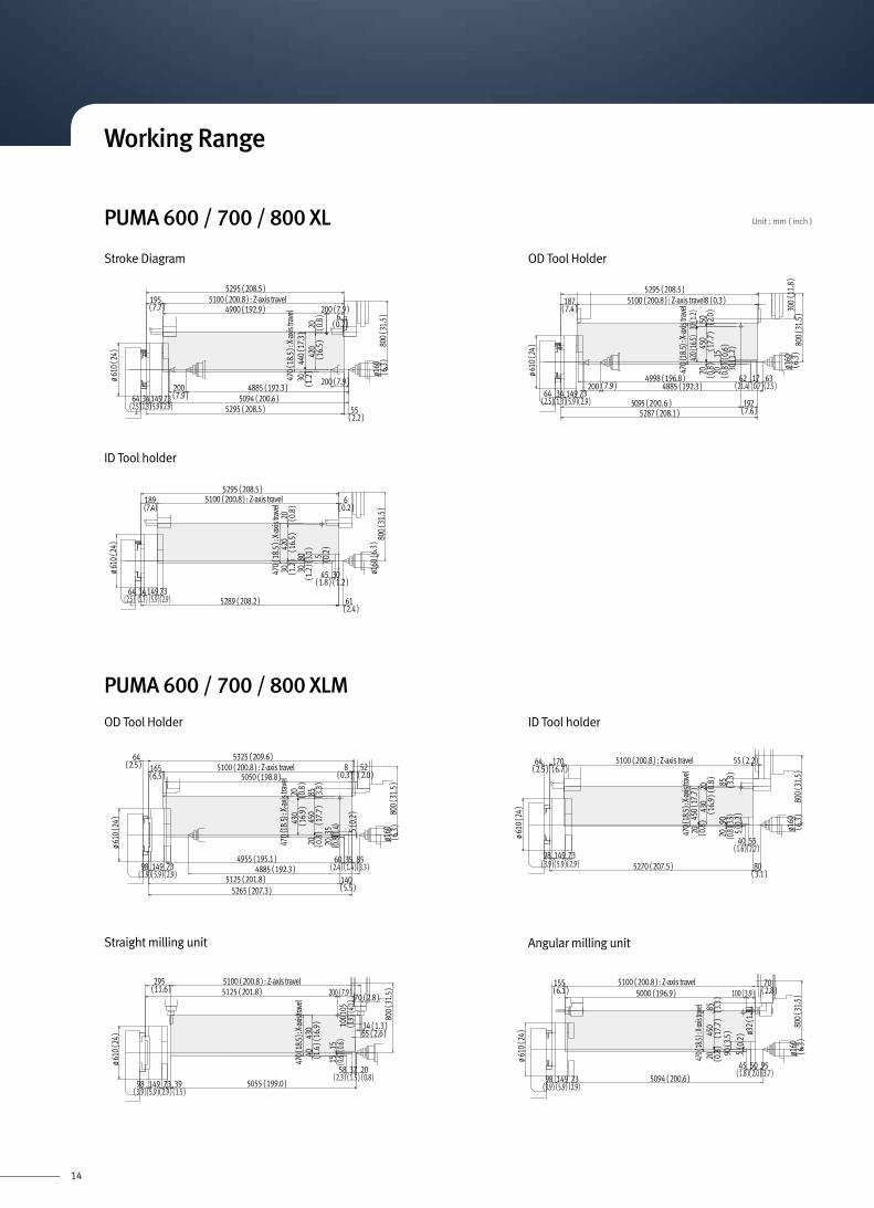
Unit : mm ( inch )
Working Range
OD Tool Holder
PUMA 600 / 700 / 800 XLM
ID Tool holder
Straight milling unit Angular milling unit

15
ø 610
( 24
)
3300 [ 5100 ] ( 129.9 [ 200.8 ] )
3470 [ 5270 ] ( 136.6 [ 207.5 ] ) 80
75 55325
15
17064
400 (
15.7
) ( X-
axis
Trave
l )38
0 ( 1
5.0
)20
360
20 85
730
160
55
( 0.6
)
( 3.1 )
( 3.0 ) ( 12.8 ) ( 2.2 )
(6.7)(2.5)
( 0.8
)( 0
.8 )
( 3.3
)10
( 0.4
)( 1
4.2
)
( 28.
7 )
( 2.2 )
20 ( 0
.8 )90 ( 3.5
)
( 6.3
)
ø 610
( 24 )
982790 [ 4590 ] (109.8 [ 108.7 ] ) 350 358575
3085 [ 4885 ] ( 121.5 [ 192.3 ] )3325 [ 5125 ] ( 130.9 [ 201.8 ] ) 140
3465 [ 5265 ] ( 136.4 [ 207.3 ] )
149 73
3300 [ 5100 ] ( 129.9 [ 200.8 ] ) ( Z-axis Travel ) 8 523250 [ 5050 ] ( 128.0 [ 198.8 ] )
1653525 [ 5325 ] ( 138.8 [ 209.6 ] )64
400 (
15.7
) ( X-
axis
Trave
l )36
0 ( 1
4.2
)38
020 20
15
10
730
160
265
8520
( 0.8
)( 2.5 )
( 6.5 )
( 5.9 ) ( 2.9 )( 3.9 )
( 0.3 )( 2.0 )( 3
.3 )
( 15.
0 )
( 0.8
)
(0.8
)
(0.4
)
( 1.4 )
( 5.5 )
( 3.0 ) ( 13.8 ) ( 3.3 )( 1
0.4
)( 2
8.7
)
(0.6
)
( 6.3
)
ø 610
( 24 )
ø 34
15 160
730
98 73149
ø 53
0 ( 2
0.9
)ø
530
( 20.
9 )
3300 [ 5100 ] ( 129.9 [ 200.8 ] ) 703200 [ 5000 ] ( 126.0 [ 196.9 ] ) 100
155
400 (
15.7
) ( X-
axis
Trave
l )38
020
75 330 5095
85
(0.6
)
10( 0
.4 )
( 6.1 ) ( 2.8 )
( 2.0 ) ( 3.7 )( 3.0 ) ( 13.0 )
90( 3
.5 )
( 3.9 )
( 3.3
)( 1
5.0 )
( 0.8
)
( 5.9 )( 2.9 )( 3.9 )
98 73149( 5.9 )( 2.9 )( 3.9 )
( 28.
7 )
( 6.3
)
( 1.3
)
ø 610
( 24 )
3300 [ 5100 ] (129.9 [ 200.8 ] ) ( Z-axis Travel )295
98 3973149
400 (
15.7
) ( X-
axis
Trave
l )36
0
30 15
730
100
5
75 37280 20
6534 ( 1.3 )
70
40
( 11.6 )
( 1.5 ) ( 0.8 )( 3.0 ) ( 11.0 )
( 0.6 )( 14.2
)( 1
.6 ) ( 1
.2 ) (
3.9
)105
( 4.1 )
( 2.6 )
( 2.8 )
( 5.9 )( 2.9 )( 3.9 ) ( 1.5 )
( 28.
7 )
( 0.2 )
ø 530
( 20.
9 )
Unit : mm ( inch )
295(11.6)
3300 [5100] (129.9 [200.8]) : Z-axis travel
70 (2.8)
58(2.3)
37(1.5)
20(0.8)
15 (0.6
)15 (0.6
)
360
(14.
2)40 (1.6
)
400 (
15.7
) : X-
axis
trave
l
34 (1.3)100
(3.9
)105
(4.1
)
ø 610
(24)
149(5.9)
73(2.9)
65(2.6)
730 (
28.7
)
98(3.9)
39(1.5)
[5125] ([201.8]) 200 (7.9)
[5055] ([199.0])
165(6.5)
3300 [5100] (129.9 [200.8]) : Z-axis travel 8(0.3)
52(2.0)
85 (3.3
)
ø160
(6.3
)35 (1.4
)
5 (0.
2)
20 (0.8
)
380
(15.
0)20 (0.8
)
20 (0.8
)36
0(1
4.2)
400 (
15.7
) : X-
axis
trave
l
3085 [4885] (121.5 [192.3])60
(2.4)35
(1.4)85
(3.3)3325 [5125] (130.9 [201.8])140
(5.5)3465 [5265] (136.4 [207.3])
ø 610
( 24 ) 73
0 (28
.7)26
5(1
0.4)3250 [5050] (128.0 [198.8])
3525 [5325] (138.8 [209.6])
3155 [4955] (124.2 [195.1])
64(2.5)
149(5.9)
73(2.9)
98(3.9)
170(6.7)
3300 [5100] (129.9 [200.8]) : Z-axis travel55(2.2)
85 (3.3
)
400 (
15.7
) : X-
axis
trave
l
ø160
(6.3
)
90 (3.5
)5 (
0.2)
20 (0.8
)40
(1.6)55
(2.2)
80(3.1)
ø 610
(24)
730 (
28.7
)
3470 [5270] (136.6 [207.5])
64(2.5)
380
(15.
0)20 (0.8
)20 (0.8
)36
0(1
4.2)
149(5.9)
73(2.9)
98(3.9)
155(6.1)
3300 [5100] (129.9 [200.8]) : Z-axis travel 70(2.8)
45(1.8)
50(2.0)
95(3.7)
90 (3
.5)
5 (0.
2)
100 (3.9)
ø32
(1.3
)85 (3.3
)38
0(1
5.0)
20 (0.8
)
400 (
15.7
) : X-
axis
trave
l
ø160
(6.3
)73
0 (28
.7)
ø 610
(24)
3200 [5000] (126.0 [196.9])
[5094] ([200.6])149(5.9)
73(2.9)
98(3.9)
ø900 ( 35.4 )
20 ( 0.8 )450 ( 17.7 )300 ( 11.8 ) 50( 2.0 )
40 ( 1.6 )
ø80 ( 3.2 )
75 ( 3
.0 )
ø301.6
( 11.9)
40 ( 1.6 )70 ( 2.8 )
ø330.1
( 1 3.0
)
ø640 ( 25.2 )
60 ( 2
.4 )
ø835.7 ( 32.9 )
( MAX. TOOL SWING )
470 ( 18.5 )350 ( 13.8 )( X-AXIS TRAVEL )
( MAX. TURNING DIA. )
ø288 ( 11.3 )
350 ( 13.8 )
40( 1.6 )
390 ( 15.4 )
ø282.3 ( 11.1 )
265 ( 10.4 ) 45 ( 1.8 )310 ( 12.2 ) 40 ( 1.6 ) 450 ( 17.7 ) 20 ( 0.8 )350 ( 13.8 ) 470 ( 18.5 )
X-AXIS TRAVEL
( 3.4
) 58
( 10.4
) 562
ø282.3 ( 11.1 )
ø900 ( 35.4 )
MAX. TURING DIA.
ø310.8( 12.2 )
ø279.9 ( 11.0 )
ø622 ( 24.5 )MAX.ø34 ( 1.3 )
( MAX TOOL SWING )
ø939.4 ( 37.0 )
MAX.ø34 ( 1.3 )
ø284.3 ( 11.2 )
ø80 ( 3.2 )
100 ( 3.9 )
ø284.3( 11.2 )
369.4( 14.5 )
345 (
13.6
)
380 ( 15.0 ) 20 ( 0.8 )
200 s
t( 7
.9 )10
0( 3
.9 )
100
( 3.9
)
400 st ( 15.7 )265( 10.4 )
85( 3.3 )
730 ( 28.7 )
270( 10.6 )
ø 620 ( 24.4 ) ø 620 ( 24.4 )
ø 282 ( 11.1 )
ø 282 ( 11.1 )
ø 80( 3.1 )ø 284( 11.2)
ø 939.4( 37.0 )
ø 310
.8( 1
2.2 )
ø 750 (
29.5 )
50( 2.0 )
584 (
23.0
)
295(11.6)
3300 [5100] (129.9 [200.8]) : Z-axis travel
70 (2.8)
58(2.3)
37(1.5)
20(0.8)
15 (0.6
)15 (0.6
)
360
(14.
2)40 (1.6
)
400 (
15.7
) : X-
axis
trave
l
34 (1.3)100
(3.9
)105
(4.1
)
ø 610
(24)
149(5.9)
73(2.9)
65(2.6)
730 (
28.7
)
98(3.9)
39(1.5)
[5125] ([201.8]) 200 (7.9)
[5055] ([199.0])
165(6.5)
3300 [5100] (129.9 [200.8]) : Z-axis travel 8(0.3)
52(2.0)
85 (3.3
)
ø160
(6.3
)35 (1.4
)
5 (0.
2)
20 (0.8
)
380
(15.
0)20 (0.8
)
20 (0.8
)36
0(1
4.2)
400 (
15.7
) : X-
axis
trave
l
3085 [4885] (121.5 [192.3])60
(2.4)35
(1.4)85
(3.3)3325 [5125] (130.9 [201.8])140
(5.5)3465 [5265] (136.4 [207.3])
ø 610
( 24 ) 73
0 (28
.7)26
5(1
0.4)3250 [5050] (128.0 [198.8])
3525 [5325] (138.8 [209.6])
3155 [4955] (124.2 [195.1])
64(2.5)
149(5.9)
73(2.9)
98(3.9)
170(6.7)
3300 [5100] (129.9 [200.8]) : Z-axis travel55(2.2)
85 (3.3
)
400 (
15.7
) : X-
axis
trave
l
ø160
(6.3
)
90 (3.5
)5 (
0.2)
20 (0.8
)
40(1.6)
55(2.2)
80(3.1)
ø 610
(24)
730 (
28.7
)
3470 [5270] (136.6 [207.5])
64(2.5)
380
(15.
0)20 (0.8
)20 (0.8
)36
0(1
4.2)
149(5.9)
73(2.9)
98(3.9)
155(6.1)
3300 [5100] (129.9 [200.8]) : Z-axis travel 70(2.8)
45(1.8)
50(2.0)
95(3.7)
90 (3
.5)
5 (0.
2)
100 (3.9)
ø32
(1.3
)85 (3.3
)38
0(1
5.0)
20 (0.8
)
400 (
15.7
) : X-
axis
trave
l
ø160
(6.3
)73
0 (28
.7)
ø 610
(24)
3200 [5000] (126.0 [196.9])
[5094] ([200.6])149(5.9)
73(2.9)
98(3.9)
ø900 ( 35.4 )
20 ( 0.8 )450 ( 17.7 )300 ( 11.8 ) 50( 2.0 )
40 ( 1.6 )
ø80 ( 3.2 )
75 ( 3
.0 )
ø301.6
( 11.9)
40 ( 1.6 )70 ( 2.8 )
ø330.1
( 1 3.0
)
ø640 ( 25.2 )
60 ( 2
.4 )
ø835.7 ( 32.9 )
( MAX. TOOL SWING )
470 ( 18.5 )350 ( 13.8 )( X-AXIS TRAVEL )
( MAX. TURNING DIA. )
ø288 ( 11.3 )
350 ( 13.8 )
40( 1.6 )
390 ( 15.4 )
ø282.3 ( 11.1 )
265 ( 10.4 ) 45 ( 1.8 )310 ( 12.2 ) 40 ( 1.6 ) 450 ( 17.7 ) 20 ( 0.8 )350 ( 13.8 ) 470 ( 18.5 )
X-AXIS TRAVEL
( 3.4
) 58
( 10.4
) 562
ø282.3 ( 11.1 )
ø900 ( 35.4 )
MAX. TURING DIA.
ø310.8( 12.2 )
ø279.9 ( 11.0 )
ø622 ( 24.5 )MAX.ø34 ( 1.3 )
( MAX TOOL SWING )
ø939.4 ( 37.0 )
MAX.ø34 ( 1.3 )
ø284.3 ( 11.2 )
ø80 ( 3.2 )
100 ( 3.9 )
ø284.3( 11.2 )
369.4( 14.5 )
345 (
13.6
)
380 ( 15.0 ) 20 ( 0.8 )
200 s
t( 7
.9 )10
0( 3
.9 )
100
( 3.9
)
400 st ( 15.7 )265( 10.4 )
85( 3.3 )
730 ( 28.7 )
270( 10.6 )
ø 620 ( 24.4 ) ø 620 ( 24.4 )
ø 282 ( 11.1 )
ø 282 ( 11.1 )
ø 80( 3.1 )ø 284( 11.2)
ø 939.4( 37.0 )
ø 310
.8( 1
2.2 )
ø 750 (
29.5 )
50( 2.0 )
584 (
23.0
)
Tool Interference DiagramPUMA 600 / 700 / 800 XL
PUMA 600 / 700 / 800 LY / XLY
PUMA 600 / 700 / 800 XLM
OD Tool Holder ID Tool holder
Straight milling unit Angular milling unit
PUMA 600 / 700 / 800 LY [ XLY ]

16
PUMA 600 / 700 / 800 XL
PUMA 600 / 700 / 800 XLM / LY / XLY
Unit : mm ( inch )
(1)
Standard
Standard
U-Drill Cap(1)
I.D Tool Holder( H 50 )
(6)
Face Tool Holder(1)
O.D Tool Holder(□32 )
Extended O.D Tool Holder
(2)
O.D Tool Clamper
(3)
ø20-H80ø25-H80ø32-H80
ø40-H80ø60-H80
Boring Bar Sleeves
ø32ø40
ø50ø60
U-Drill Sleeves
Boring Bar
ø50 Boring Bar
U-Drill
Drill
12st Turret
MT#2-H80MT#3-H80
MT#4-H80MT#5-H80
Drill Sockets
Straight Milling Head
Angular Milling Head
Collet Adapter ER32
Milling Arbor Adapter
Weldon Adapter
ø6~ø32 ( 12 Pieces )Milling Collet ER 50
Spanner Wrench
ø20-H80ø25-H80ø32-H80
ø40-H80ø60-H80
Boring Bar Sleeves
U-Drill Cap
(2)
(1)
(1)
(2)
(2)
Plug(12)
(1)
ø80 U-Drill
MT#2-H80MT#3-H80
MT#4-H80MT#5-H80
Drill SocketsDrill
ø80 U-Drill
ø32 ø40 ø50 ø60
U-Drill SleevesI.D Tool Holder( H80 )
(3)
Boring Bar
Face Tool Holder(1)
Extended O.D Tool Holder
(1)
O.D Tool Holder(3)
O.D Tool □32
OD 22mm
ID 20mm
Tooling System
opt.
opt.
opt.
12st Turret( BMT 85P )

17
Unit : mm ( inch )PUMA 600 / 700 / 800 XL series
PUMA 600 / 700 / 800 LY series
Top View
Top View
Front View
Front View
Side View
Side View
225( 8.9 )
850( 33.5 )
720( 28.3 )
960( 37.8 )
900( 35.4 )
900( 35.4 )
900( 35.4 )
900( 35.4 )
130( 5.1 )
900( 35.4 )
915( 36.0 )
990( 39.0 )
40 ( 1.6
)12
80( 5
0.4
)40
( 1.6
)
40( 1
.6 )93
5 ( 3
6.8
) 40
( 1.6
)11
00( 4
3.3
)
590
( 23.
2 )
Electric Power Inlet
1834
.5 ( 7
2.2
)
565( 22.2 )
2035( 80.1 )
243( 9.6 )
2843 ( 111.9 )
1725 ( 67.9 )
Coolant Pump
2760
( 108
.7 )
9800 ( 385.8 ) 98 ( 3.9 )
430( 16.9 )
1791( 70.5 )
1870( 73.6 )
5( 0.2 )
1870( 73.6 )
1781( 70.1 )
1753( 69.0 )
300( 11.8 )
5( 0
.2 )
Chip Conveyor
knaT tnalooCknaT tnalooC9898 ( 389.7 )
11112 ( 437.5 )
1214( 47.8 )
1020
( 40.
2 )
450( 17.7 )
7260 ( 285.8 )
253( 10.0)
520 ( 20.5 )
1410( 55.5 )
2490.01 ( 98.0 )330.29 ( 13.0 )2820.3 ( 111.0 )
7430( 292.5 )
2764
.71
( 108
.8 )
1161.58( 45.7 )
1020
( 40.
2 )
560( 22.0 )
450( 17.7 )
600( 23.6 )
1321( 52.0 )
1340( 52.8 )
5( 0.2 )
1250( 49.2 )
1161( 45.7 )
1155( 45.5 )
428( 16.9 )
570
( 22.
4 )
1960
( 77.
2 )
75 ( 3
.0 )
2605 ( 102.6 )215.3 ( 8.5 )
2605
( 102
.6 )
2605
( 102
.6 )
215
( 8.5
)
225( 8.9 )
850( 33.5 )
720( 28.3 )
960( 37.8 )
900( 35.4 )
900( 35.4 )
900( 35.4 )
900( 35.4 )
130( 5.1 )
900( 35.4 )
915( 36.0 )
990( 39.0 )
40 ( 1.6
)12
80( 5
0.4
)40
( 1.6
)
40( 1
.6 )93
5 ( 3
6.8
) 40
( 1.6
)11
00( 4
3.3
)
590
( 23.
2 )
Electric Power Inlet
1834
.5 ( 7
2.2
)
565( 22.2 )
2035( 80.1 )
243( 9.6 )
2843 ( 111.9 )
1725 ( 67.9 )
Coolant Pump27
60( 1
08.7
)9800 ( 385.8 ) 98 ( 3.9 )
430( 16.9 )
1791( 70.5 )
1870( 73.6 )
5( 0.2 )
1870( 73.6 )
1781( 70.1 )
1753( 69.0 )
300( 11.8 )
5( 0
.2 )
Chip Conveyor
knaT tnalooCknaT tnalooC9898 ( 389.7 )
11112 ( 437.5 )
1214( 47.8 )
1020
( 40.
2 )
450( 17.7 )
7260 ( 285.8 )
253( 10.0)
520 ( 20.5 )
1410( 55.5 )
2490.01 ( 98.0 )330.29 ( 13.0 )2820.3 ( 111.0 )
7430( 292.5 )
2764
.71
( 108
.8 )
1161.58( 45.7 )
1020
( 40.
2 )
560( 22.0 )
450( 17.7 )
600( 23.6 )
1321( 52.0 )
1340( 52.8 )
5( 0.2 )
1250( 49.2 )
1161( 45.7 )
1155( 45.5 )
428( 16.9 )
570
( 22.
4 )
1960
( 77.
2 )
75 ( 3
.0 )
2605 ( 102.6 )215.3 ( 8.5 )
2605
( 102
.6 )
2605
( 102
.6 )
215
( 8.5
)
225( 8.9 )
850( 33.5 )
720( 28.3 )
960( 37.8 )
900( 35.4 )
900( 35.4 )
900( 35.4 )
900( 35.4 )
130( 5.1 )
900( 35.4 )
915( 36.0 )
990( 39.0 )
40 ( 1.6
)12
80( 5
0.4
)40
( 1.6
)
40( 1
.6 )93
5 ( 3
6.8
) 40
( 1.6
)11
00( 4
3.3
)
590
( 23.
2 )
Electric Power Inlet
1834
.5 ( 7
2.2
)
565( 22.2 )
2035( 80.1 )
243( 9.6 )
2843 ( 111.9 )
1725 ( 67.9 )
Coolant Pump
2760
( 108
.7 )
9800 ( 385.8 ) 98 ( 3.9 )
430( 16.9 )
1791( 70.5 )
1870( 73.6 )
5( 0.2 )
1870( 73.6 )
1781( 70.1 )
1753( 69.0 )
300( 11.8 )
5( 0
.2 )
Chip Conveyor
knaT tnalooCknaT tnalooC9898 ( 389.7 )
11112 ( 437.5 )
1214( 47.8 )
1020
( 40.
2 )
450( 17.7 )
7260 ( 285.8 )
253( 10.0)
520 ( 20.5 )
1410( 55.5 )
2490.01 ( 98.0 )330.29 ( 13.0 )2820.3 ( 111.0 )
7430( 292.5 )
2764
.71
( 108
.8 )
1161.58( 45.7 )
1020
( 40.
2 )
560( 22.0 )
450( 17.7 )
600( 23.6 )
1321( 52.0 )
1340( 52.8 )
5( 0.2 )
1250( 49.2 )
1161( 45.7 )
1155( 45.5 )
428( 16.9 )
570
( 22.
4 )
1960
( 77.
2 )
75 ( 3
.0 )
2605 ( 102.6 )215.3 ( 8.5 )
2605
( 102
.6 )
2605
( 102
.6 )
215
( 8.5
)
225( 8.9 )
850( 33.5 )
720( 28.3 )
960( 37.8 )
900( 35.4 )
900( 35.4 )
900( 35.4 )
900( 35.4 )
130( 5.1 )
900( 35.4 )
915( 36.0 )
990( 39.0 )
40 ( 1.6
)12
80( 5
0.4
)40
( 1.6
)
40( 1
.6 )93
5 ( 3
6.8
) 40
( 1.6
)11
00( 4
3.3
)
590
( 23.
2 )
Electric Power Inlet18
34.5
( 72.
2 )
565( 22.2 )
2035( 80.1 )
243( 9.6 )
2843 ( 111.9 )
1725 ( 67.9 )
Coolant Pump
2760
( 108
.7 )
9800 ( 385.8 ) 98 ( 3.9 )
430( 16.9 )
1791( 70.5 )
1870( 73.6 )
5( 0.2 )
1870( 73.6 )
1781( 70.1 )
1753( 69.0 )
300( 11.8 )
5( 0
.2 )
Chip Conveyor
knaT tnalooCknaT tnalooC9898 ( 389.7 )
11112 ( 437.5 )
1214( 47.8 )
1020
( 40.
2 )
450( 17.7 )
7260 ( 285.8 )
253( 10.0)
520 ( 20.5 )
1410( 55.5 )
2490.01 ( 98.0 )330.29 ( 13.0 )2820.3 ( 111.0 )
7430( 292.5 )
2764
.71
( 108
.8 )
1161.58( 45.7 )
1020
( 40.
2 )
560( 22.0 )
450( 17.7 )
600( 23.6 )
1321( 52.0 )
1340( 52.8 )
5( 0.2 )
1250( 49.2 )
1161( 45.7 )
1155( 45.5 )
428( 16.9 )
570
( 22.
4 )
1960
( 77.
2 )
75 ( 3
.0 )
2605 ( 102.6 )215.3 ( 8.5 )
2605
( 102
.6 )
2605
( 102
.6 )
215
( 8.5
)
External Dimensions

18
Description Unit P600XL P700XL P800XL P600XLM P700XLM P800XLM P600LY [ XLY ] P700LY [ XLY ] P800LY [ XLY ]
Capacity
Swing over bed mm ( inch ) 1140 ( 44.9 )
Swing over saddle mm ( inch ) 1000 ( 39.4 )
Max. turning diameter mm ( inch ) 900 ( 35.4 ) 750 ( 29.5 )
Max. work length mm ( inch ) 5050 ( 198.8 ) 3250 [ 5050 ] (128.0 [ 198.8 ] )
Bar working diameter mm ( inch ) 117 ( 4.6 ) 164 ( 6.5 ) - 117 ( 4.6 ) 164 ( 6.5 ) - 117 ( 4.6 ) 164 ( 6.5 ) -
Spindle Bore - 152 181 320 152 181 320 152 181 320
Carriage
Travel distance X-axis mm ( inch ) 470 ( 18.5 ) 400 (15.7)
Z-axis mm ( inch ) 5100 ( 200.8 ) 3300 [ 5100 ] ( 129.9 [ 200.8 ] ) 3250 [ 5100 ]( 128.0 [ 200.8 ] )
Y-axis mm ( inch ) - 200 ( 7.9 )
Feedrate
Rapid traverse X-axis m/min ( ipm ) 12 ( 472.4 )
Z-axis m/min ( ipm ) 10 ( 393.7 )
Y-axis m/min ( ipm ) - 6 ( 236.2 )
Max. cutting feedrate X / Z / Y axis mm/rev ( ipr ) 500 ( 19.7 )
Main spindle power ( cont. / 30min ) kW ( Hp ) 37 / 45 ( 49.6 / 60.3 )
Main Spindle
Chuck size mm ( inch ) 450 ( 17.7 ) 530 ( 20.9 ) - 450 ( 17.7 ) 530 ( 20.9 ) - 450 ( 17.7 ) 530 ( 20.9 ) -
Spindle speed r/min 1800 1500 750 1800 1500 750 1800 1500 750
Spindle nose ASA A2#15 A1#15 A1#20 A2#15 A1#15 A1#20 A2#15 A1#15 A1#20
Spindle bearing diameter ( Front ) mm ( inch ) 200 ( 7.9 ) 240 ( 9.4 ) 400 ( 15.7 ) 200 ( 7.9 ) 240 ( 9.4 ) 400 200 ( 7.9 ) 240 ( 9.4 ) 400 ( 15.7 )
Cs spindle index angle deg - 360 ( 0.001 )
Tool post
Turret type - DI Holder base BMT85P
No. of tool stations ea 12
O.D tool size mm ( inch ) 32 x 32 ( 1.3 x 1.3 )
Boring bar diameter mm ( inch ) ø 80 ( 3.1 )
Indexing time ( 1st swivel ) s 0.25
Rotary tool speed - 3000
Rotary tool collets - - ER 50
Tail Stock
Quill diameter mm ( inch ) 160 ( 6.3 )
Quill bore taper MT MT#6 ( Live )
Quill travel mm ( inch ) 200 ( 7.9 )
Motors
Main spindle power ( cont. / 30min ) kW ( Hp ) 37 / 45 ( 49.6 / 60.3 )
Servo motor X-axis kW ( Hp ) 7 ( 9.4 )
Z-axis kW ( Hp ) 9 ( 12.1 )
Y-axis kW ( Hp ) - 3 ( 4.0 )
Rotary tool spindle motor kW ( Hp ) - 11 ( 14.8 )
Power Source
Electric power supply kVA 64.44 68.6 78
Machine Size
Height mm ( inch ) 2770 ( 109.1 )
Length mm ( inch ) 9860 ( 388.2 ) 7430 [ 9860 ] ( 292.5 [ 388.2 ] )
width mm ( inch ) 3020 ( 118.9 )
weight kg ( lb ) 26000 ( 57319.3 ) 23000 [ 26000 ] ( 905.5 [ 57319.3 ] )
NC System Fanuc 32i-A
Chuck Option
Standard Feature
• Coolant supply equipment• Full enclosure chip and coolant shield• Hydraulic power unit• Leveling jack screw & plates• Live center• Lubrication equipment• Work light
Optional Feature
• Air blast for chuck jaw cleaning• Air gun• Automatic power off• Automatic measuring system
( in process touch probe )• Bar feeder interface• Chip conveyor• Chip bucket• Dead center ( MT #6 )• Dual chucking pressure• Hardened & ground jaws
• Hydraulic chuck ( PUMA 600 / 700 )• Hydraulic chuck & Cylinder ( PUMA 800 / B )• Hydraulic steady rest• Manual steady rest• Oil skimmer• Pressure switch for chucking pressure check• Proximity switches for chuck clamp detection• Signal tower ( yellow, red, green )• Tool monitoring system• Tool pre setter ( hydraulic type )
• The specifications and information above-mentioned may be changed without prior notice.• For more details, please contact Doosan
Machine Specifications
• Design and specifications are subject to change without notice.• Doosan is not responsible for difference between the information in the catalogue and the actual machine.

19
CONTROLS- Controlled path 1 path- Controlled axes X,Z X,Z,C *1 X,Z,C,Y *2
- Angular axis control- Cs contouring control- Backlash compensation 0 ~ ±9999 pulses- Chamfering on / off- HRV2 control- Inch / Metric conversion- Interlock All axes / each axis- Least input command 0.001 / 0.0001 mm/inch- Machine lock All axes / each axis- Mirror image- Overtravel- Position switch- Stored stroke check 1
OPERATION- Automatic operation ( memory )- DNC Operation with Memory card- Buffer register- Dry run- Handle incremental feed X1, X10, X100- Program restart- Wrong operation prevention- Manual intervention and return- Manual pulse generator 1 ea- Manual reference position return- Program number search
INTERPOLATION FUNCTIONS- Nano interpolation- Positioning G00- 1st. Reference position return Manual, G28- 2nd. reference position return G30- Continuous threading- Linear interpolation G01- Multiple threading- Reference position return check G27- Skip G31- Thread cutting / Synchronous cutting- Thread cutting retract- Variable lead threading
FEED FUNCTION- Automatic acceleration / deceleration- Cutting feedrate clamp- Feed per revolution- Feedrate override ( 10% unit ) 0 - 200 %- Manual per revolution feed- Rapid traverse override F0, 25, 100 %
AUXILIARY / SPINDLE SPEED FUNCTION- Constant surface speed control- High speed M / S / T interface- Spindle orientation- M - code function M3 digits- Rigid tapping- S - code function S4 / S5 digits- Spindle serial output S4 / S5 digits- Spindle speed overridew 0 - 150 %
PROGRAM INPUT- Absolute / incremental programming
- Addition of custom macro common variables#100~#199,#500~#999
- Automatic coordinate system setting- Canned cycle for drilling / Turning- Circular interpolation by R programming- Coordinate system setting G50- Coordinate system shift- Custom macro- Pocket calculator type decimal point programming- Diameter / radius programming ( X axis )- Direct drawing dimension programming- Direct input of coordinate system shift- G code system A / B / C- Label skip- Macro executor- Manual absolute on and off- Maximum program dimension ±9 digit- Multiple repetitive canned cycle G70 - G76- Optional block skip 9 piece- Parity check- Plane selection G17, G18, G19- Program file name 32 characters- Program stop / end ( M00, M01 / M02, M30 )- Programmable data input G10- SUB program call 10 folds nested- Tape code : ISO / EIA auto recognition
EIA RS422 / ISO840- Work coordinate system G52 - G59
TOOL FUNCTION / TOOL COMPENSATION- Automatic tool offset- Direct input of offset value measured- T - code function T2+2 digits- Tool geometry / wear compensation- Tool life management - Tool nose radius compensation- Tool offset G43, G44, G49- Tool offset pairs ±6 digits : 64 pairs- Tool offset value counter input- Y-axis offset *2
EDITING OPERATION- Back ground editting- Number of registered programs 500 ea- Part program editing- Part program storage size 640m ( 256 kB )
SETTING AND DISPLAY- Actual cutting feedrate display- Alarm display- Alarm history display- Display of spindle speed and T code at all screens- Multi-language display- Program comment display 31 characters- Run hours / part count display- Status display- Operating monitor screen
DATA INPUT / OUTPUT- External work number search 15 points- Memory card input / output- RS232C interface- Automatic data backup
OTHERS- Display unit 10.4" Color TFT LCD- MDI unit- PMC system
INTERFACE FUNCTION- Ethernet function Embedded ethernet
OPERATION GUIDANCE FUNCTION- EZ Guidei ( Conversational Programming Solution )
OPTIONAL SPECIFICATIONSAXIS CONTROL- Chuck and tail stock barrier- Stored pitch error compensation
( XL size bed : standard )- Stored stroke 2 and 3
OPERATION- Manual handle feed 2 units- Manual handle interruption- Reference position shift
INTERPOLATION FUNCTIONS- 3rd / 4th reference point reurn- Arbitrary speed threading- Circular threading- Interruption type custom macro- Multi step skip
FEED FUNCTION- AI Contour control I ( Look-ahead block no. is Max30 )
G5.1 Q1
PROGRAM INPUT- Addition of workpiece coordinate system pair
48 pairs- Automatic corner override- Optional block skip ( Soft operator's panel )
9 piece- Pattern data input
TOOL FUNCTION / TOOL COMPENSATION- Addition of tool pairs for tool life management
128 pairs- Tool Load Monitoring system- Tool offset pairs 99 / 400 / 999 pairs
EDITING OPERATION- Number of registered programs
1000 ( 512kB ) ea- Part program storage length 1280 / 2560 / 5120 m- Play back
DATA INPUT/OUTPUT- Fast ethernet / Data server Only for 1 path- DNC1 control- Remote buffer Only for 1 path
ROBOT INTERFACE- Robot interface with PMC I / O module
*1 : PUMA 600 / 700 / 800 XLM *2 : PUMA 600 / 700 / 800 LY / XLY
NC Unit SpecificationsFANUC 32i
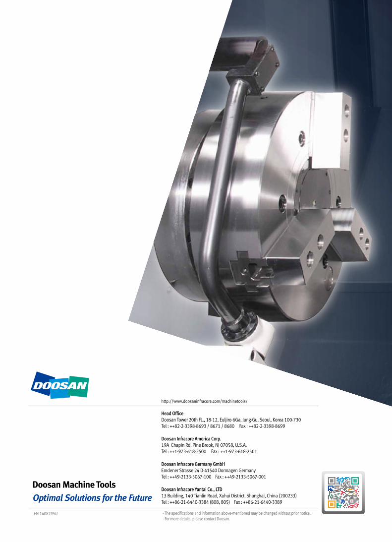
Head OfficeDoosan Tower 20th FL., 18-12, Euljiro-6Ga, Jung-Gu, Seoul, Korea 100-730 Tel : ++82-2-3398-8693 / 8671 / 8680 Fax : ++82-2-3398-8699
Doosan Infracore America Corp.19A Chapin Rd. Pine Brook, NJ 07058, U.S.A. Tel : ++1-973-618-2500 Fax : ++1-973-618-2501
Doosan Infracore Germany GmbHEmdener Strasse 24 D-41540 Dormagen Germany Tel : ++49-2133-5067-100 Fax : ++49-2133-5067-001
Doosan Infracore Yantai Co., LTD13 Building, 140 Tianlin Road, Xuhui District, Shanghai, China (200233) Tel : ++86-21-6440-3384 (808, 805) Fax : ++86-21-6440-3389
- The specifications and information above-mentioned may be changed without prior notice.- For more details, please contact Doosan.
http://www.doosaninfracore.com/machinetools/
EN 140829SU