heating, ventilation, and air conditioning design...
TRANSCRIPT

Heating, Ventilation, and Air Conditioning Design Strategy for a Hot-Humid Production Builder P. Kerrigan Building Science Corporation
March 2014

NOTICE
This report was prepared as an account of work sponsored by an agency of the United States government. Neither the United States government nor any agency thereof, nor any of their employees, subcontractors, or affiliated partners makes any warranty, express or implied, or assumes any legal liability or responsibility for the accuracy, completeness, or usefulness of any information, apparatus, product, or process disclosed, or represents that its use would not infringe privately owned rights. Reference herein to any specific commercial product, process, or service by trade name, trademark, manufacturer, or otherwise does not necessarily constitute or imply its endorsement, recommendation, or favoring by the United States government or any agency thereof. The views and opinions of authors expressed herein do not necessarily state or reflect those of the United States government or any agency thereof.
Available electronically at http://www.osti.gov/bridge
Available for a processing fee to U.S. Department of Energy and its contractors, in paper, from:
U.S. Department of Energy Office of Scientific and Technical Information
P.O. Box 62 Oak Ridge, TN 37831-0062
phone: 865.576.8401 fax: 865.576.5728
email: mailto:[email protected]
Available for sale to the public, in paper, from: U.S. Department of Commerce
National Technical Information Service 5285 Port Royal Road Springfield, VA 22161 phone: 800.553.6847
fax: 703.605.6900 email: [email protected]
online ordering: http://www.ntis.gov/ordering.htm
Printed on paper containing at least 50% wastepaper, including 20% postconsumer waste

iii
Heating, Ventilation, and Air Conditioning Design Strategy for a Hot-Humid Production Builder
Prepared for:
The National Renewable Energy Laboratory
On behalf of the U.S. Department of Energy’s Building America Program
Office of Energy Efficiency and Renewable Energy
15013 Denver West Parkway
Golden, CO 80401
NREL Contract No. DE-AC36-08GO28308
Prepared by:
P. Kerrigan
Building Science Corporation
30 Forest Street
Somerville, MA 02143
NREL Technical Monitor: Cheryn Metzger
Prepared under Subcontract No. KNDJ-0-40337-03
March 2014

iv
[This page left blank]

v
Contents List of Figures ............................................................................................................................................ vi List of Tables ............................................................................................................................................. vii Definitions ................................................................................................................................................. viii Executive Summary ................................................................................................................................... ix 1 Introduction ........................................................................................................................................... 1
1.1 Purpose .................................................................................................................................1 1.2 Research Questions ..............................................................................................................2 1.3 Previous Research ................................................................................................................2 1.4 Whole-House Specifications ................................................................................................2
2 Development of Duct Strategy ............................................................................................................ 5 2.1 Initial Design Development .................................................................................................5
3 HVAC Design and Implementation ................................................................................................... 10 3.1 Plan 4127 ...........................................................................................................................10 3.2 Plan 4128 ...........................................................................................................................15 3.3 Plan 4069 ...........................................................................................................................19
4 Testing Results ................................................................................................................................... 23 4.1 Overview ............................................................................................................................23 4.2 Plan 4127 ...........................................................................................................................23 4.3 Plan 4128 ...........................................................................................................................26 4.4 Plan 4069 ...........................................................................................................................27 4.5 Duct Test Discussion .........................................................................................................30
5 Duct Design Cost Analysis ................................................................................................................ 31 5.1 Plan 4127 ...........................................................................................................................31 5.2 Plan 4128 ...........................................................................................................................33 5.3 Plan 4069 ...........................................................................................................................35 5.4 Cost Analysis Discussion ...................................................................................................35
6 Code Compliance Analysis ............................................................................................................... 37 7 Conclusions ........................................................................................................................................ 41 References ................................................................................................................................................. 43 Appendix .................................................................................................................................................... 45

vi
List of Figures Figure 1. Plan 4127 ...................................................................................................................................... 3 Figure 2. Plan 4128 ...................................................................................................................................... 3 Figure 3. Plan 4069 ...................................................................................................................................... 3 Figure 4. Duct design strategy 1—Dropped ceilings and mechanical closet ....................................... 5 Figure 5. Duct design strategy 2—Buried ducts and mechanical closet .............................................. 6 Figure 6. Duct design strategy 3—Dropped ceiling and mechanical coffer ......................................... 7 Figure 7. Duct design strategy 4—Ductwork and AHU in mechanical coffer ....................................... 8 Figure 8. Duct design strategy 5—Unvented cathedralized attic ........................................................... 9 Figure 9. Duct layout for plan 4127 ......................................................................................................... 11 Figure 10. Plan 4127 mechanical closet section .................................................................................... 11 Figure 11. Plan 4127 mechanical closet during framing visit ............................................................... 12 Figure 12. Plan 4127 constructed duct coffer ........................................................................................ 12 Figure 13. Jump duct coffer ..................................................................................................................... 13 Figure 14. HVAC runouts in dropped ceiling at plan 4127 .................................................................... 14 Figure 15. Plan 4127 mechanical closet in attic ..................................................................................... 14 Figure 16. Plan 4127 add-on mechanical closet .................................................................................... 15 Figure 17. Plan 4128 second-floor duct layout ...................................................................................... 16 Figure 18. Plan 4128 mechanical closet building section ..................................................................... 17 Figure 19. Plan 4128 mechanical closet ................................................................................................. 17 Figure 20. Plan 4128 return duct in knee wall ........................................................................................ 18 Figure 21. Plan 4128 first-floor duct layout ............................................................................................ 18 Figure 22. Plan 4128 dining room duct coffer ........................................................................................ 19 Figure 23. Plan 4069 second-floor duct layout ...................................................................................... 19 Figure 24. Plan 4069 upstairs mechanical closet coffer ....................................................................... 20 Figure 25. Plan 4069 second-floor guest suite coffer ........................................................................... 20 Figure 26. Plan 4069 insulation trough ................................................................................................... 21 Figure 27. Plan 4069 first-floor duct layout ............................................................................................ 21 Figure 28. Plan 4069 first floor kitchen “raceway” location ................................................................. 22 Figure 29. Plan 4128 front elevation ........................................................................................................ 23 Figure 30. Plan 4127 design register flow versus measured register flow plot ................................. 25 Figure 31. Plan 4128 front elevation ........................................................................................................ 26 Figure 32. Plan 4128 design register flow versus measured register flow plot ................................. 27 Figure 33. Plan 4069 front elevation ........................................................................................................ 28 Figure 34. Inconsistencies in air barrier at floor joist in attic kneewall space ................................... 28 Figure 35. Plan 4069 design register flow versus measured register flow plot ................................. 29 Figure 36. Plan 4127 BEopt source energy savings versus the BA Benchmark—end use
breakdown ........................................................................................................................................... 46 Figure 37. Plan 4127 BEopt parametric graph ....................................................................................... 46 Figure 38. Plan 4128 BEopt source energy savings versus the BA Benchmark—end use
breakdown ........................................................................................................................................... 47 Figure 39. Plan 4128 BEopt parametric graph ....................................................................................... 47 Figure 40. Plan 4069 BEopt source energy savings versus the BA Benchmark—end use
breakdown ........................................................................................................................................... 48 Figure 41. Plan 4069 BEopt parametric graph duct layouts ................................................................. 48 Unless otherwise indicated, all figures were created by BSC.

vii
List of Tables Table 1. Floor Plan Dimensions and Areas .............................................................................................. 3 Table 2. Summary of DWH – Houston Energy Efficiency Package Components ................................ 4 Table 3. Plan 4127 Infiltration Testing Results....................................................................................... 24 Table 4. Plan 4127 Duct Testing Results ................................................................................................ 24 Table 5. Plan 4127 HVAC ESPs ................................................................................................................ 25 Table 6. Plan 4127 Room Pressure Measurements ............................................................................... 25 Table 7. Plan 4128 Infiltration Testing Results....................................................................................... 26 Table 8. Plan 4128 Duct Testing Results ................................................................................................ 26 Table 9. Plan 4128 HVAC ESPs ................................................................................................................ 27 Table 10. Plan 4128 Room Pressure Measurements ............................................................................. 27 Table 11. Plan 4069 Infiltration Testing Results .................................................................................... 29 Table 12. Plan 4069 Duct Testing Results .............................................................................................. 29 Table 13. Plan 4069 HVAC ESPs .............................................................................................................. 30 Table 14. Plan 4069 Room Pressure Measurements ............................................................................. 30 Table 15. Plan 4127 Enclosure Costs ...................................................................................................... 32 Table 16. Plan 4127 Mechanical Costs .................................................................................................... 32 Table 17. Plan 4128 Enclosure Costs ...................................................................................................... 34 Table 18. Plan 4128 Mechanical Costs .................................................................................................... 34 Table 19. Plan 4069 Enclosure Costs ...................................................................................................... 36 Table 20. Plan 4069 Mechanical Costs .................................................................................................... 36 Table 21. Plan 4127 IECC 2006 Compliance Analysis Specifications ................................................. 39 Table 22. Plan 4127 IECC 2006 Energy Cost Compliance Chart .......................................................... 40 Table 23. DWH Cost Data for BEopt Analysis ........................................................................................ 45
Unless otherwise indicated, all tables were created by BSC.

viii
Definitions
AFUE Annual fuel utilization efficiency
AHU Air handling unit
BA Building America Program
BSC Building Science Corporation
CFIS Central fan integrated supply
CFM Cubic feet per minute
DWH David Weekley Homes
EF Energy factor
ESP External static pressure
HERS Home Energy Rating System
HVAC Heating, ventilation, and air conditioning
IECC International Energy Conservation Code
OSB Oriented strand board
SEER Seasonal energy efficiency ratio
SHGC Solar heat gain coefficient
TESP Total external static pressure
WIC Inches water column
XPS Extruded polystyrene

ix
Executive Summary
BSC worked directly with the David Weekley Homes (DWH) – Houston division to redesign three current floor plans in order to locate the heating, ventilation, and air conditioning (HVAC) system in conditioned space. The purpose of this project is to develop a cost-effective design for moving the HVAC system into conditioned space. In addition, BSC conducted energy analysis to calculate the most economical strategy for increasing the energy performance of future production houses. This is in preparation for the upcoming code changes in 2015. The builder wishes to develop an upgrade package that will allow for a seamless transition to the new code mandate.
The following research questions were addressed by this research project.
1. What is the most cost-effective, best-performing, and most easily replicable method of locating ducts inside conditioned space for a hot-humid production home builder that constructs one- and two-story single-family detached residences?
2. What is a cost-effective and practical method of achieving 50% source energy savings versus the 2006 International Energy Conservation Code for a hot-humid production builder?
3. How accurate are the pre-construction whole house cost estimates compared to confirmed post-construction actual cost?
BSC and the builder developed a duct design strategy that employs a system of dropped ceilings and attic coffers for moving the ductwork from the vented attic to conditioned space. The furnace has been moved to either a mechanical closet in the conditioned living space or a coffered space in the attic.
The development of a design for duct coffers in the attic space allows DWH to embrace the strategy of locating ductwork in conditioned space, in its existing housing stock, without having to rely solely on dropped ceilings. The builder does recognize that a full series of dropped ceilings, without any coffers, would be the most economical strategy for locating ducts. However, the builder perceives this design as having a negative impact on aesthetics and could not be attractive to its customer base. This is one of the more important developments in this research work, as DWH (and its customers) greatly value full ceiling height in the majority of spaces and wish to avoid dropped ceilings as much as possible. The main contribution of this research was to provide a working alternative for builders who wish to move their HVAC systems into conditioned spaces without extended dropped ceilings plus a mechanical closet, or converting to a full unvented cathedralized attic.
Relocating the HVAC system to within conditioned space resulted in significant energy savings toward the goal of achieving 50% energy savings versus the 2006 International Energy Conservation Code. Moving the HVAC system inside conditioned space saves around 4%–5% in source energy use and can reduce the Home Energy Rating System Index by around 4 points. The costs for implementing this duct design strategy on the three research homes was in the range of $6,000–$10,000; however, the builder expects that this figure can improve in future homes to around $4,000–$6,000. This is more affordable compared to the popular strategy of

x
constructing an unvented cathedralized attic with spray polyurethane foam, which for these plans could cost in the range of $10,000–$15,000.
The additional energy upgrades implemented for meeting the 2015 code provision includes improvements to the walls, ceiling, infiltration rate, air conditioner and hot water heater. The predicted costs for these improvements were very accurate compared to the post-construction confirmed costs, as this production builder is adept and experienced with costing specific components.

1
1 Introduction
1.1 Purpose Through the advanced new construction energy efficiency packages evaluation in Texas, Building Science Corporation (BSC) seeks to acquire important information about the performance of energy-efficient technology packages designed for a production builder in a hot-humid climate. This research addresses several important gaps and barriers:
• Cost-competitive and replicable designs for locating ducts inside conditioned space by a production builder
• Complete high performance technology packages that will comply with expected future code improvements.
Through this work, BSC expects to collect information about:
• Cost and implementation issues with locating the entire heating, ventilation, and air conditioning (HVAC) system in conditioned space in production homes.
• Comparisons between the various predicted energy savings methodologies available in industry (source energy savings versus the Building America (BA) Benchmark compared to site energy savings provided by commonly used residential modeling software)
The technology package proposed for this pilot community project is most appropriate for single-family detached production houses. From a building science perspective, the Houston package is suitable for other hot-humid production environments. The information gained through this research about the implementation of the technology package at a production community scale and the longer term performance data from the community of houses will support widespread deployment of this package in new housing across the hot-humid climate zone.
The most immediate impact of the research project will be to inform the work of David Weekley Homes (DWH) – Houston. Lessons learned both in the economics of the variations in design and constructability can be applied to the future business model of the production builder.
The adoption of the new and more stringent 2012 International Energy Conservation Code (IECC) is greatly reducing the performance gap between code-built homes and those that are constructed to meet an energy efficiency standard (Bailes 2012). A major component of the 2012 IECC is the mandatory inclusion of the entire HVAC system in conditioned space. This mandate is forcing builders to establish cost-effective strategies for moving the ductwork inside the thermal enclosure. The project also has the potential to impact BA measure guidelines on improving the replicability and cost effectiveness of designs that not only meet the current energy code, but will meet future proposed building code improvements.
This presents a major opportunity for considering the importance of a cost-effective method of locating ducts inside conditioned space in order for production home builders to remain competitive in the market. There is also an opportunity to gauge what house designs will meet the likely 2015 IECC provisional mandate. DWH sees this as part of a long-term strategy for

2
maintaining a high performance design that will be compliant with potential future code provisions. This work will also provide important design and construction data for other production builder in a hot-humid climate as well as for local Home Energy Rating System (HERS) raters and architects.
1.2 Research Questions The following research questions will be answered by this project.
1. What is the most cost-effective, best-performing, and most easily replicable method of locating ducts inside conditioned space for a hot-humid production home builder that constructs one- and two-story single-family detached residences?
2. What is a cost-effective and practical method of achieving 50% source energy savings versus the 2006 IECC for a hot-humid production builder?
3. How accurate are the pre-construction whole house cost estimates compared to confirmed post-construction actual cost?
1.3 Previous Research Moving ducts inside conditioned space offers the highest energy savings compared to other energy-related improvements (Lubliner et al. 2008). As energy programs and codes become more stringent, this strategy will need to be implemented more throughout the country.
Previous research has provided guidance and identified risks with duct design strategies, specifically buried ducts (Chasar and Withers 2013; Griffiths et al. 2004). General duct design strategies have been developed for low-energy homes to inform designers and builders (Burdick 2011). Previous studies have calculated potential energy losses due to ducts being located in unconditioned space as being in the range of 25%–40% (Andrews 2003), thus prioritizing the need for developing affordable strategies for moving the HVAC system within the thermal enclosure.
Many of the whole-house characteristics for these homes are connected to previous research work on advanced framing, the effectiveness of ventilation systems, and other whole-house energy efficiency packages for affordable housing as described below.
The enclosure included in the Houston energy efficiency package uses advanced framing (BSC 2009; Lstiburek and Grin 2010) and insulating sheathing as the primary thermal control layer and the drainage plane (Baker 2006; BSC 2007).
This work also draws on whole house energy efficiency research work that has been published by BSC the Builder’s Field Guides series (Lstiburek 2005) and in research reports on community scale evaluations in hot-humid and other climate zones (BSC 2010).
The package specifies a central fan integrated ventilation supply (CFIS) system that has been extensively researched and tested by BSC (Rudd 2008; Hendron et al. 2008).
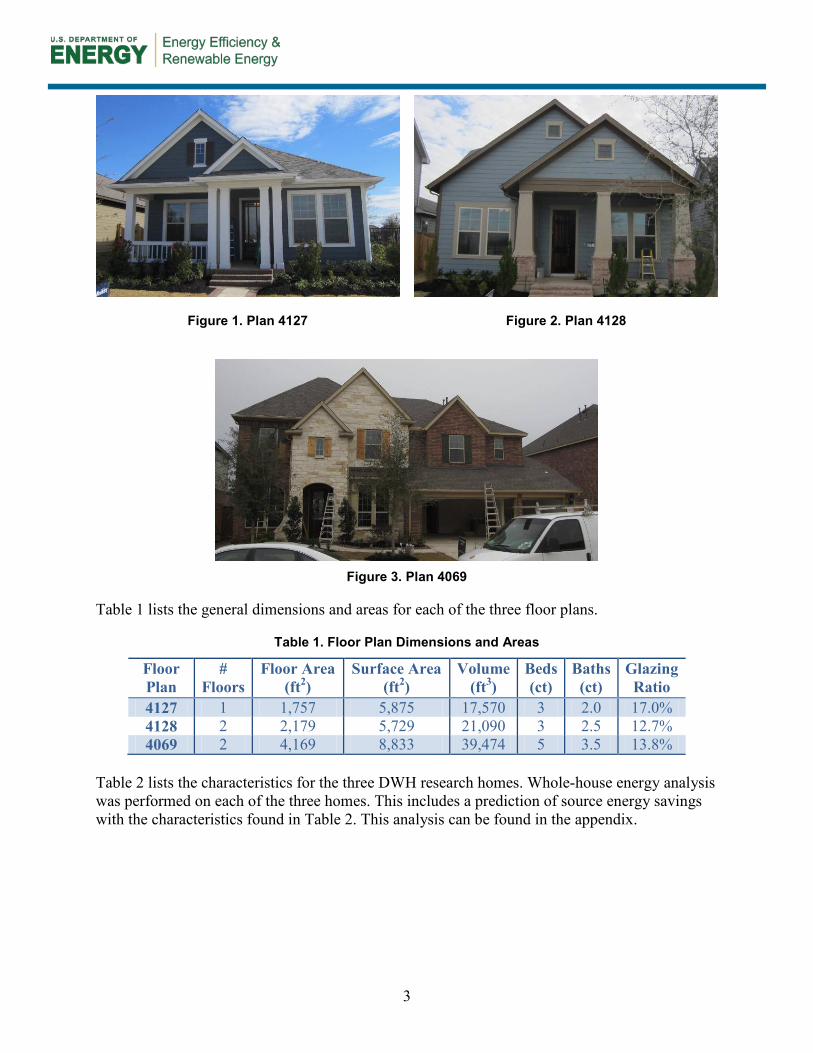
1.4 Whole-House Specifications Figure 1 through Figure 3 show the front elevation of the three research houses for this project.
3
Figure 1. Plan 4127
Figure 2. Plan 4128
Figure 3. Plan 4069
Table 1 lists the general dimensions and areas for each of the three floor plans.
Table 1. Floor Plan Dimensions and Areas
Floor Plan
# Floors
Floor Area (ft2)
Surface Area (ft2)
Volume (ft3)
Beds (ct)
Baths (ct)
Glazing Ratio
4127 1 1,757 5,875 17,570 3 2.0 17.0% 4128 2 2,179 5,729 21,090 3 2.5 12.7% 4069 2 4,169 8,833 39,474 5 3.5 13.8%
Table 2 lists the characteristics for the three DWH research homes. Whole-house energy analysis was performed on each of the three homes. This includes a prediction of source energy savings with the characteristics found in Table 2. This analysis can be found in the appendix.

4
Table 2. Summary of DWH – Houston Energy Efficiency Package Components
Enclosure Specifications Roof
Description Dark color asphalt shingles on rafter roof – vented attic Insulation R-50 blown fiberglass
Walls
Description 2 × 6 @ 24 in. o.c. with advanced framing with insulating sheathing
Insulation R-19 fiberglass batts with R-3.75 ¾-in. XPSa insulating sheathing Foundation
Description Slab on grade Insulation Uninsulated
Windows Description Double pane vinyl framed with LoE3 spectrally selective glazing
U-Value U = 0.29 SHGCb SHGC = 0.22
Infiltration Specification 0.25 CFM 50/ft2 enclosure @ 50 Pa
Performance Test Average = 0.22 CFM 50/ft2 enclosure @ 50 Pa Mechanical Systems Specifications Heating
Description 96% AFUEc natural gas furnace Manufacturer and Model Lennox Cooling
Description 16 SEERd two-stage air conditioner Manufacturer and Model Lennox Domestic Hot Water
Description Tank gas water heater (EFe = 0.62) Manufacturer and Model Rheem Distribution
Description R-6 flex ducts in conditioned space Leakage maximum 5% duct leakage to outside
Ventilation
Description Central fan integrated supply-only system with fan cycler 33% Duty cycle: 10 minutes on; 20 minutes off, 50 CFM flow
Manufacturer and Model Aprilaire 8126 Ventilation Control System fan cycler Return Pathways
Description Mostly jump ducts in bedrooms and study Some active returns in master suites
a Extruded polystyrene b Solar heat gain coefficient c Annual fuel utilization efficiency d Seasonal energy efficiency ratio
e Energy factor
5
2 Development of Duct Strategy
BSC visited DWH – Houston in August 2012 and met with representatives from DWH and Davis Air Conditioning (HVAC contractor). An initial meeting was conducted to discuss and develop a proposed duct design strategy. Three homes currently under construction, representing a range of DWH house and HVAC system types, were toured over a 2-day period to be used as examples for developing strategies for locating ducts within conditioned space.
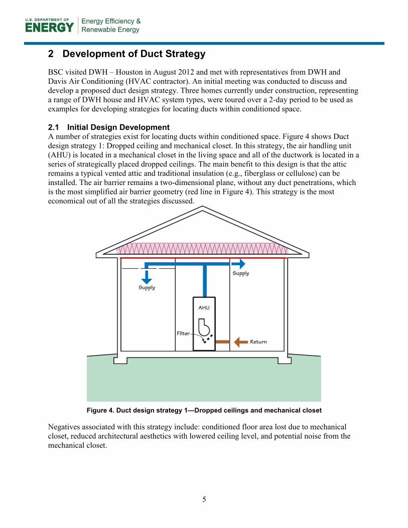
2.1 Initial Design Development A number of strategies exist for locating ducts within conditioned space. Figure 4 shows Duct design strategy 1: Dropped ceiling and mechanical closet. In this strategy, the air handling unit (AHU) is located in a mechanical closet in the living space and all of the ductwork is located in a series of strategically placed dropped ceilings. The main benefit to this design is that the attic remains a typical vented attic and traditional insulation (e.g., fiberglass or cellulose) can be installed. The air barrier remains a two-dimensional plane, without any duct penetrations, which is the most simplified air barrier geometry (red line in Figure 4). This strategy is the most economical out of all the strategies discussed.
Figure 4. Duct design strategy 1—Dropped ceilings and mechanical closet
Negatives associated with this strategy include: conditioned floor area lost due to mechanical closet, reduced architectural aesthetics with lowered ceiling level, and potential noise from the mechanical closet.

6
The risk of AHU closet noise can be abated by implementing the following measures:
• Installing a variable-speed AHU or furnace with an electronically commutated motor, as these motors are quieter than traditional permanent split capacitor motors.
• Installing a weather-stripped door at the mechanical closet
• Designing the duct system to operate at low velocities in the supply and return plenums. BSC recommends designing the supply plenum for 500–750 ft/min and the return plenum at 250–550 ft/min. Also, velocities at the return grille should not exceed 350 ft/min to prevent whistling (Rudd 2006).
Despite the drawbacks, this is a very popular strategy with builders and is the best performing design from an energy standpoint.
Figure 5 shows Duct design strategy 2: Buried ducts and mechanical closet. In this strategy, the air handler is again in a mechanical closet but the ductwork is located in the attic closer to the ceiling plane. Traditional insulation (e.g., fiberglass or cellulose) is installed and the ductwork is covered in insulation. A benefit to this strategy is that dropped ceilings are no longer required.
Figure 5. Duct design strategy 2—Buried ducts and mechanical closet
Drawbacks associated with this strategy include: conditioned floor area lost due to mechanical closet and duct penetrations now exist through the air barrier which require additional air sealing. Also, the potential exists for condensation to form on the ductwork, even with insulated flex, as the ductwork is buried in an air and vapor-permeable insulation (Chasar and Withers 2013; Griffiths et al. 2004).

7
Figure 6 shows Duct design strategy 3: Dropped ceiling and mechanical coffer. In this strategy, the AHU is located in an air-sealed and insulated coffered closet in the attic space and the ductwork is located in strategically placed dropped ceilings. Benefits to this strategy include: the removal of the AHU from conditioned living space, no duct penetrations through the air barrier.
Figure 6. Duct design strategy 3—Dropped ceiling and mechanical coffer
Drawbacks to this design include: added complexity for the air barrier, as it is now a three-dimensional extrusion, and potential added cost for construction, air sealing, and insulating of the mechanical coffer (red line in Figure 6 indicates ceiling air barrier). Also, access to the coffer space is required and may be difficult with a complicated attic design.
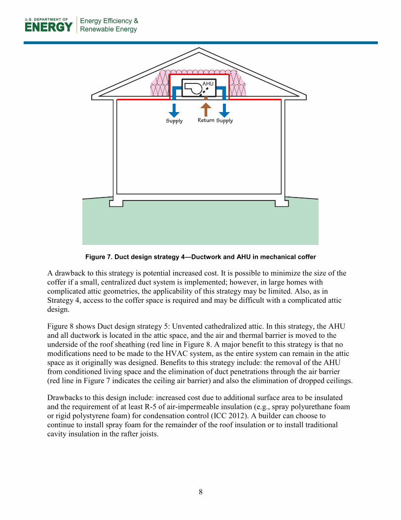
Figure 7 shows Duct design strategy 4: Ductwork and AHU in mechanical coffer. In this strategy, the AHU and all ductwork are located in an air-sealed and insulated coffered closet in the attic. Benefits to this strategy include: the removal of the AHU from conditioned living space and the elimination of duct penetrations through the air barrier (red line in Figure 7 indicates the ceiling air barrier) and also the elimination of dropped ceilings.
8
Figure 7. Duct design strategy 4—Ductwork and AHU in mechanical coffer
A drawback to this strategy is potential increased cost. It is possible to minimize the size of the coffer if a small, centralized duct system is implemented; however, in large homes with complicated attic geometries, the applicability of this strategy may be limited. Also, as in Strategy 4, access to the coffer space is required and may be difficult with a complicated attic design.
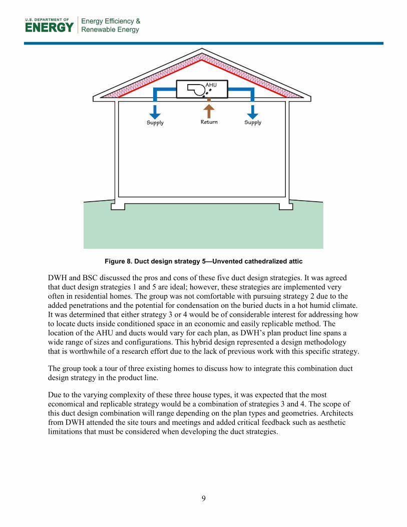
Figure 8 shows Duct design strategy 5: Unvented cathedralized attic. In this strategy, the AHU and all ductwork is located in the attic space, and the air and thermal barrier is moved to the underside of the roof sheathing (red line in Figure 8. A major benefit to this strategy is that no modifications need to be made to the HVAC system, as the entire system can remain in the attic space as it originally was designed. Benefits to this strategy include: the removal of the AHU from conditioned living space and the elimination of duct penetrations through the air barrier (red line in Figure 7 indicates the ceiling air barrier) and also the elimination of dropped ceilings.
Drawbacks to this design include: increased cost due to additional surface area to be insulated and the requirement of at least R-5 of air-impermeable insulation (e.g., spray polyurethane foam or rigid polystyrene foam) for condensation control (ICC 2012). A builder can choose to continue to install spray foam for the remainder of the roof insulation or to install traditional cavity insulation in the rafter joists.
9
Figure 8. Duct design strategy 5—Unvented cathedralized attic
DWH and BSC discussed the pros and cons of these five duct design strategies. It was agreed that duct design strategies 1 and 5 are ideal; however, these strategies are implemented very often in residential homes. The group was not comfortable with pursuing strategy 2 due to the added penetrations and the potential for condensation on the buried ducts in a hot humid climate. It was determined that either strategy 3 or 4 would be of considerable interest for addressing how to locate ducts inside conditioned space in an economic and easily replicable method. The location of the AHU and ducts would vary for each plan, as DWH’s plan product line spans a wide range of sizes and configurations. This hybrid design represented a design methodology that is worthwhile of a research effort due to the lack of previous work with this specific strategy.
The group took a tour of three existing homes to discuss how to integrate this combination duct design strategy in the product line.
Due to the varying complexity of these three house types, it was expected that the most economical and replicable strategy would be a combination of strategies 3 and 4. The scope of this duct design combination will range depending on the plan types and geometries. Architects from DWH attended the site tours and meetings and added critical feedback such as aesthetic limitations that must be considered when developing the duct strategies.
10
3 HVAC Design and Implementation
Three floor plans were chosen for this research work, spanning a range of house sizes and complexities. Each floor plan was selected such that different categories of HVAC system design can be evaluated:
• Single-story house with one HVAC system—Plan 4127
• Two-story house with one HVAC system—Plan 4128
• Two-story house with two HVAC systems—Plan 4069.
Architects from DWH drafted the duct designs for each floor plan, based off of discussions with BSC on the three existing homes included in the site tour. The architects shared their preferences for locating dropped ceilings with BSC and this guided the development of the duct designs for each of the three floor plans. The list below outlines DWH’s preference for dropped ceilings (in order from most preferred to not willing to drop):
1. Hallways
2. Bathrooms
3. Bedrooms and Study
4. Main living areas (i.e., living room, kitchen, breakfast, dining room).
In areas where dropped ceilings are not preferred, the team advocated the construction of duct coffers in the attic space. It was agreed that the duct coffers would be constructed of duct board and would be installed by the HVAC installer rather than the framer as a cost-saving measure. Otherwise an extra visit would be required of framing crews after the ductwork was installed to build the coffers, and the coffers themselves would be constructed with a more expensive wood-based material. The HVAC contractor was instructed to tape all seams and to spray foam or caulk all joints between the coffers and the ceiling plane.
3.1 Plan 4127 Plan 4127 represents a smaller, single-story floor plan (1,757 ft2); thus, DWH expressed a desire to avoid locating a mechanical closet in conditioned space. It was determined that a mechanical coffer could be constructed above parts of the utility closet, bedroom 3, and the master walk-in closet. The attic hatch could be located in the utility closet. DWH determined that the 4127 duct strategy would be located in a system of dropped ceilings along with a single duct coffer for the dining and study. The utilization of a coffer in this area was required to avoid dropping ceilings in the dining and study, which are designated as critical aesthetic areas.
Figure 9 shows the designed duct layout for plan 4127. The diagonally hatched area designates the mechanical closet in the attic space. The shaded areas designate dropped ceilings for locating the ductwork in conditioned space. The black triangle icons represent the location of wall supply registers that are serving the adjoining rooms. The red square represents the location of the furnace in the mechanical closet. Rooms with dropped ceilings in them have ceiling supply grilles but are not specifically labeled on the drawings. All bedrooms have jump ducts for passive return. Please refer to the appendix for the duct layout.

11
Figure 9. Duct layout for plan 4127
Figure 10 shows a building section with the mechanical closet framing above the utility and master closet. DWH considered eliminating the right-hand kneewall (circled in red), thus effectively extending the mechanical closet space to the exterior wall. However, DWH ultimately decided to construct the kneewall in order to limit the extra space conditioning energy use due to the addition of unnecessary volume and enclosure area to conditioned space.
Figure 10. Plan 4127 mechanical closet section
Black Arrows = high wall registers Shaded Areas = dropped ceiling Diagonal Hatches = mechanical coffer Red Box = furnace

12
Figure 11 shows a photo of the mechanical closet from a site visit during framing. BSC observed a large return duct outside of the mechanical closet. The diagonal mechanical wall was subsequently moved forward to enclose the entire return ductwork in conditioned space. The two ducts on the right-hand side were located in a coffer above the bottom chord of the attic framing. All coffers were constructed by the HVAC contractor.
Figure 11. Plan 4127 mechanical closet during framing visit
Figure 12 shows those same two ducts with the coffers now constructed. Duct board is used as the coffer material and had to be notched to allow for flush installation when running perpendicular to the bottom chord of the attic framing. Caulk and/or spray foam was used to air seal the ceiling drywall to the coffers.
Figure 12. Plan 4127 constructed duct coffer

13
Figure 13 shows a jump duct coffer that is typical throughout the three research houses.
Figure 13. Jump duct coffer
It was stated during the design process that all coffers require full levels of ceiling insulation to ensure a consistent R-value throughout the ceiling plane. To this end, DWH constructed “troughs” that consist of walls of oriented strand board (OSB) or plywood adjacent to the coffers to provide a backing for the blown fiberglass. Photos of the finished trough are not available for Plans 4127 and 4128 but there are photos of this in the Plan 4069 section.
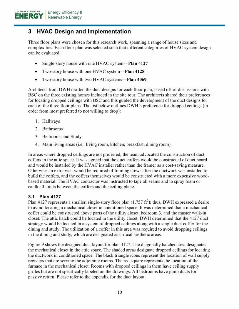
Plywood was used as the ceiling plane blocking for the dropped ceilings. Figure 14 shows runouts located in a dropped ceiling with plywood installed as the air barrier at the ceiling plane.
14
Figure 14. HVAC runouts in dropped ceiling at plan 4127
Figure 15 shows an inside view of the mechanical closet in the attic. This mechanical closet was air sealed and insulated from the inside with open cell spray polyurethane foam as the large size allowed for an insulation contractor to insulate from the inside.
Figure 15. Plan 4127 mechanical closet in attic
Figure 16 shows the add-on closet that had to be constructed to move the return ductwork inside conditioned space. This closet has a short ceiling to minimize additional volume of conditioned space.

15
Figure 16. Plan 4127 add-on mechanical closet
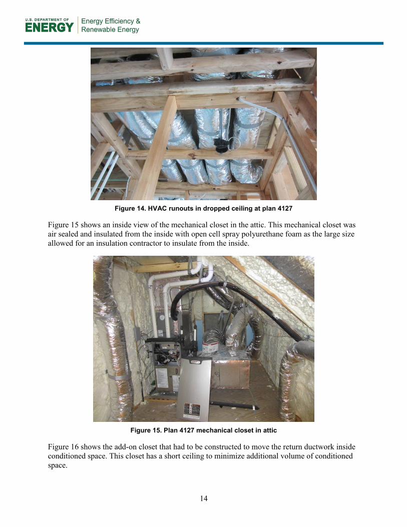
3.2 Plan 4128 Plan 4128 is a medium sized (2,179 ft2), two-story floor plan with a single HVAC system. DWH decided to utilize a kneewall space on the second floor as a mechanical closet, effectively converting that kneewall space to a small unvented cathedralized attic. The red square in Figure 17 shows the location of the furnace in the kneewall space, and the thick red line indicates the main return trunk line that terminates at a return grille at the stair landing. The mechanical closet is accessible by a door in the adjacent bedroom. DWH determined that duct system would be located in a series of dropped ceiling in both the first and second floors.
Figure 17 shows the designed second-floor duct layout for Plan 4128. The shaded areas designate dropped ceilings for locating the ductwork in conditioned space. The black arrows represent the location of wall supply registers that are serving the adjoining rooms. The red square represents the location of the furnace in the mechanical closet. Room with dropped ceiling in them have ceiling supply grilles but are not specifically labeled on the drawings. All bedrooms have jump ducts for passive return. Please refer to the appendix for the duct layout.
16
Figure 17. Plan 4128 second-floor duct layout
As a note, the option of open web floor trusses was noted both in the initial tour of the existing homes and in the design phase of the research homes. However, it was decided that open web joists would not simplify the duct layouts. The complexity of the floor framing system includes many flush beams that would eliminate the option of routing ductwork in the floor system in key locations. However, there are locations in both two-story research homes where ducts are briefly routed in the floor system where applicable, but upgrading the floor framing from dimensional lumber to open web floor trusses was not justifiable.
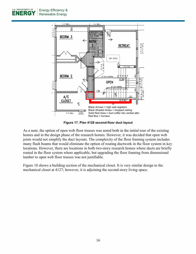
Figure 18 shows a building section of the mechanical closet. It is very similar design to the mechanical closet at 4127; however, it is adjoining the second-story living space.
Black Arrows = high wall registers Black Shaded Areas = dropped ceiling Solid Red Area = duct coffer into vented attic Red Box = furnace
17
Figure 18. Plan 4128 mechanical closet building section
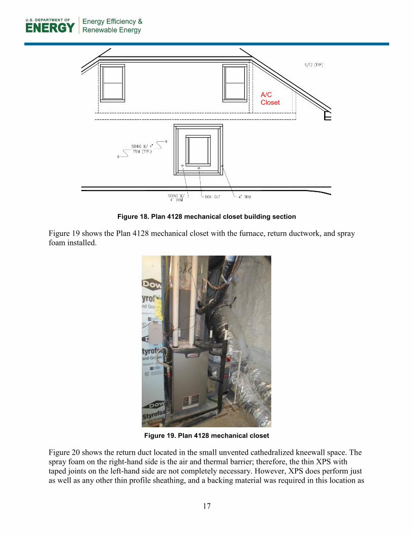
Figure 19 shows the Plan 4128 mechanical closet with the furnace, return ductwork, and spray foam installed.
Figure 19. Plan 4128 mechanical closet
Figure 20 shows the return duct located in the small unvented cathedralized kneewall space. The spray foam on the right-hand side is the air and thermal barrier; therefore, the thin XPS with taped joints on the left-hand side are not completely necessary. However, XPS does perform just as well as any other thin profile sheathing, and a backing material was required in this location as
A/C Closet

18
the left-hand wall was insulated for sound attenuation. This return duct terminates at a wall return grille on the stair landing.
Figure 20. Plan 4128 return duct in knee wall
Figure 21 shows the first floor dropped ceiling plan. The red line indicates a coffer that extends from the second-floor joists to the dining room.
Figure 21. Plan 4128 first-floor duct layout
Figure 22 shows a photo of the duct coffer during framing.
Black Arrows = high wall registers Black Shaded Areas = dropped ceiling Solid Red Area = duct coffer into vented attic
19
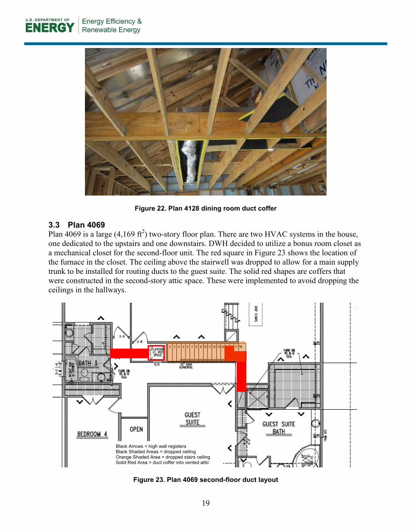
Figure 22. Plan 4128 dining room duct coffer
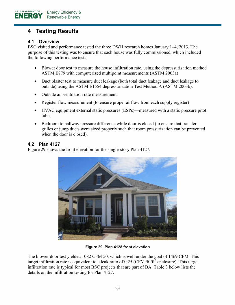
3.3 Plan 4069 Plan 4069 is a large (4,169 ft2) two-story floor plan. There are two HVAC systems in the house, one dedicated to the upstairs and one downstairs. DWH decided to utilize a bonus room closet as a mechanical closet for the second-floor unit. The red square in Figure 23 shows the location of the furnace in the closet. The ceiling above the stairwell was dropped to allow for a main supply trunk to be installed for routing ducts to the guest suite. The solid red shapes are coffers that were constructed in the second-story attic space. These were implemented to avoid dropping the ceilings in the hallways.
Figure 23. Plan 4069 second-floor duct layout
Black Arrows = high wall registers Black Shaded Areas = dropped ceiling Orange Shaded Area = dropped stairs ceiling Solid Red Area = duct coffer into vented attic

20
A coffer was constructed above the mechanical closet for the upstairs furnace allow for enough space to route the ductwork to the coffer for the left side (bedrooms 4 and 5) side of the house. Figure 24 shows this coffer and the spray foam that was used to insulate and air seal. The mechanical closet can be made shorter in future designs to save costs.
Figure 24. Plan 4069 upstairs mechanical closet coffer
Figure 25 shows the coffer on the second floor that serves the guest suite.
Figure 25. Plan 4069 second-floor guest suite coffer
As mentioned in the previous section, “troughs” constructed of OSB sheets were constructed to hold up blown fiberglass such that consistent levels of ceiling insulation can be installed over the coffers. Figure 26 shows a picture of the insulation trough that was installed at the guest suite coffer.

21
Figure 26. Plan 4069 insulation trough
Figure 27 shows the first floor duct layout for Plan 4069. The furnace for the first floor HVAC system is located in a mechanical closet adjacent to the stairs.
Figure 27. Plan 4069 first-floor duct layout
Routing ductwork to the breakfast area proved to be the most difficult challenge out of all three homes. Figure 28 shows that the floor joists are oriented perpendicular to the intended location of the duct to the breakfast area. DWH did not wish to sacrifice ceiling space in the kitchen.
Black Arrows = high wall registers Black Shaded Areas = dropped ceiling Solid Red Area = duct coffer into vented attic Red Box = furnace

22
Therefore, a “raceway” (red rectangle in Figure 27 and Figure 28) was retrofitted in the floor system to allow for the placement of the breakfast duct in the joists. In future designs DWH intends to alter the framing in order to avoid this problem or may consider open web floor joists in this location despite additional costs. A photo of the raceway after it was retrofitted in the floor framing is not available.
Figure 28. Plan 4069 first floor kitchen “raceway” location
23
4 Testing Results
4.1 Overview BSC visited and performance tested the three DWH research homes January 1–4, 2013. The purpose of this testing was to ensure that each house was fully commissioned, which included the following performance tests:
• Blower door test to measure the house infiltration rate, using the depressurization method ASTM E779 with computerized multipoint measurements (ASTM 2003a)
• Duct blaster test to measure duct leakage (both total duct leakage and duct leakage to outside) using the ASTM E1554 depressurization Test Method A (ASTM 2003b).
• Outside air ventilation rate measurement
• Register flow measurement (to ensure proper airflow from each supply register)
• HVAC equipment external static pressures (ESPs)—measured with a static pressure pitot tube
• Bedroom to hallway pressure difference while door is closed (to ensure that transfer grilles or jump ducts were sized properly such that room pressurization can be prevented when the door is closed).
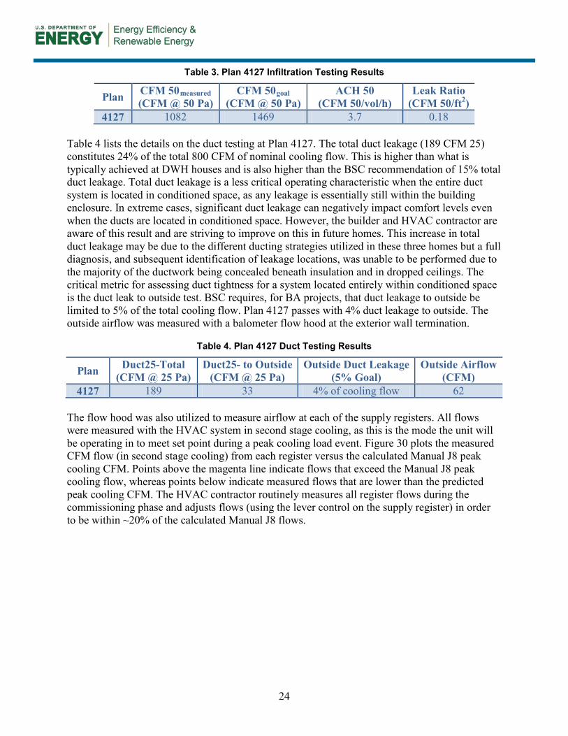
4.2 Plan 4127 Figure 29 shows the front elevation for the single-story Plan 4127.
Figure 29. Plan 4128 front elevation
The blower door test yielded 1082 CFM 50, which is well under the goal of 1469 CFM. This target infiltration rate is equivalent to a leak ratio of 0.25 (CFM 50/ft2 enclosure). This target infiltration rate is typical for most BSC projects that are part of BA. Table 3 below lists the details on the infiltration testing for Plan 4127.
24
Table 3. Plan 4127 Infiltration Testing Results
Plan CFM 50measured (CFM @ 50 Pa)
CFM 50goal (CFM @ 50 Pa)
ACH 50 (CFM 50/vol/h)
Leak Ratio (CFM 50/ft2)
4127 1082 1469 3.7 0.18 Table 4 lists the details on the duct testing at Plan 4127. The total duct leakage (189 CFM 25) constitutes 24% of the total 800 CFM of nominal cooling flow. This is higher than what is typically achieved at DWH houses and is also higher than the BSC recommendation of 15% total duct leakage. Total duct leakage is a less critical operating characteristic when the entire duct system is located in conditioned space, as any leakage is essentially still within the building enclosure. In extreme cases, significant duct leakage can negatively impact comfort levels even when the ducts are located in conditioned space. However, the builder and HVAC contractor are aware of this result and are striving to improve on this in future homes. This increase in total duct leakage may be due to the different ducting strategies utilized in these three homes but a full diagnosis, and subsequent identification of leakage locations, was unable to be performed due to the majority of the ductwork being concealed beneath insulation and in dropped ceilings. The critical metric for assessing duct tightness for a system located entirely within conditioned space is the duct leak to outside test. BSC requires, for BA projects, that duct leakage to outside be limited to 5% of the total cooling flow. Plan 4127 passes with 4% duct leakage to outside. The outside airflow was measured with a balometer flow hood at the exterior wall termination.
Table 4. Plan 4127 Duct Testing Results
Plan Duct25-Total (CFM @ 25 Pa)
Duct25- to Outside (CFM @ 25 Pa)
Outside Duct Leakage (5% Goal)
Outside Airflow (CFM)
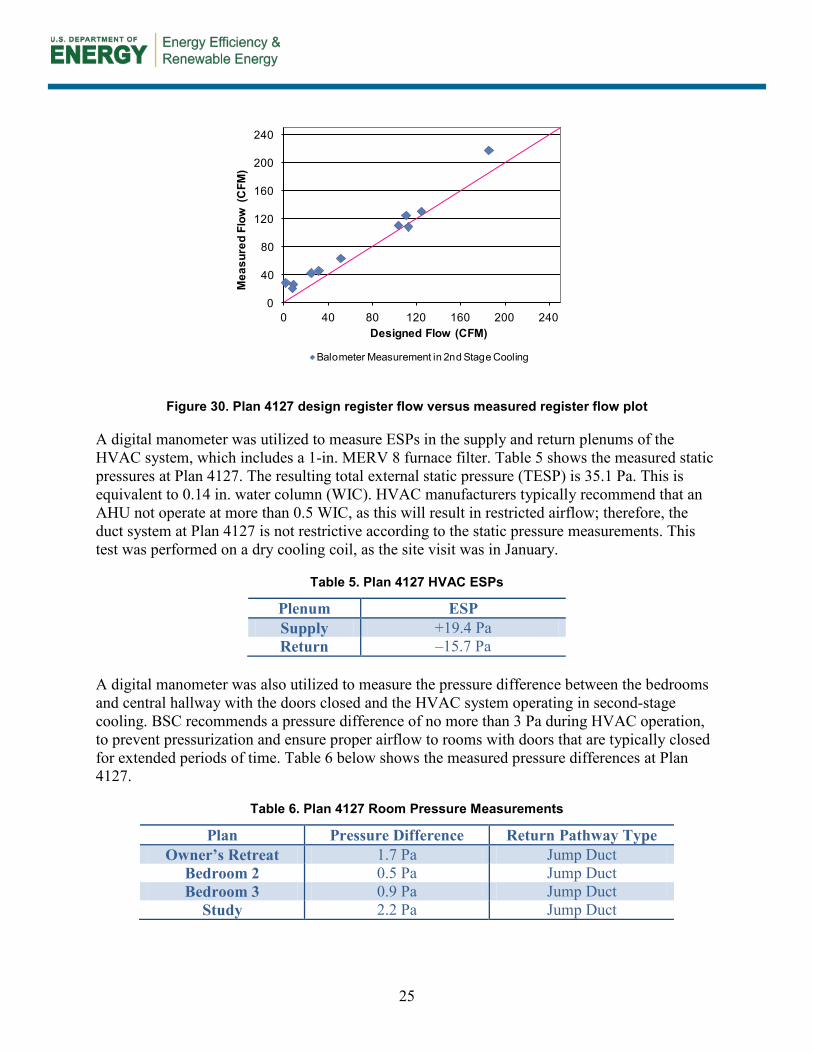
4127 189 33 4% of cooling flow 62 The flow hood was also utilized to measure airflow at each of the supply registers. All flows were measured with the HVAC system in second stage cooling, as this is the mode the unit will be operating in to meet set point during a peak cooling load event. Figure 30 plots the measured CFM flow (in second stage cooling) from each register versus the calculated Manual J8 peak cooling CFM. Points above the magenta line indicate flows that exceed the Manual J8 peak cooling flow, whereas points below indicate measured flows that are lower than the predicted peak cooling CFM. The HVAC contractor routinely measures all register flows during the commissioning phase and adjusts flows (using the lever control on the supply register) in order to be within ~20% of the calculated Manual J8 flows.
25
Figure 30. Plan 4127 design register flow versus measured register flow plot
A digital manometer was utilized to measure ESPs in the supply and return plenums of the HVAC system, which includes a 1-in. MERV 8 furnace filter. Table 5 shows the measured static pressures at Plan 4127. The resulting total external static pressure (TESP) is 35.1 Pa. This is equivalent to 0.14 in. water column (WIC). HVAC manufacturers typically recommend that an AHU not operate at more than 0.5 WIC, as this will result in restricted airflow; therefore, the duct system at Plan 4127 is not restrictive according to the static pressure measurements. This test was performed on a dry cooling coil, as the site visit was in January.
Table 5. Plan 4127 HVAC ESPs
Plenum ESP Supply +19.4 Pa Return –15.7 Pa
A digital manometer was also utilized to measure the pressure difference between the bedrooms and central hallway with the doors closed and the HVAC system operating in second-stage cooling. BSC recommends a pressure difference of no more than 3 Pa during HVAC operation, to prevent pressurization and ensure proper airflow to rooms with doors that are typically closed for extended periods of time. Table 6 below shows the measured pressure differences at Plan 4127.
Table 6. Plan 4127 Room Pressure Measurements
Plan Pressure Difference Return Pathway Type Owner’s Retreat 1.7 Pa Jump Duct
Bedroom 2 0.5 Pa Jump Duct Bedroom 3 0.9 Pa Jump Duct
Study 2.2 Pa Jump Duct
0
40
80
120
160
200
240
0 40 80 120 160 200 240
Mea
sure
d Fl
ow (
CFM
)
Designed Flow (CFM)
Balometer Measurement in 2nd Stage Cooling

26
4.3 Plan 4128 Figure 31 shows the front elevation for the two-story Plan 4128.
Figure 31. Plan 4128 front elevation
The blower door test yielded 1189 CFM 50, which is well under the goal of 1432 CFM, resulting in a leak ratio of 0.21 CFM 50/ft2 enclosure. Table 7 below lists the details on the infiltration testing for Plan 4128.
Table 7. Plan 4128 Infiltration Testing Results
Plan CFM 50measured (CFM @ 50 Pa)
CFM 50goal (CFM @ 50 Pa)
ACH 50 (CFM 50/vol/h)
Leak Ratio (CFM 50/ft2)
4128 1189 1432 3.4 0.21 Table 8 lists the details on the duct testing at Plan 4128. The total duct leakage (189 CFM 25) constitutes 14% of the total 1200 CFM of nominal cooling flow. This meets the BSC recommended maximum 15% total duct leakage. The duct leakage to outside was tested at 3% of nominal cooling flow and meets the 5% BSC requirement for duct leakage to outside.
Table 8. Plan 4128 Duct Testing Results
Plan Duct25-Total (CFM @ 25 Pa)
Duct25- to Outside (CFM @ 25 Pa)
Outside Duct Leakage (5% Goal)
Outside Airflow (CFM)
4128 162 25 3% of cooling flow 69 Figure 32 shows the measured flow versus designed flow plot. Flows that are below the specified CFM are no less than 15% below the Manual J8 calculated room CFM.

27
Figure 32. Plan 4128 design register flow versus measured register flow plot
Table 9 shows the measured static pressures at Plan 4128. The resulting TESP is 54.8 Pa. This is equivalent to 0.22 WIC; therefore, the duct system at Plan 4128 is not restrictive according to the static pressure measurements.
Table 9. Plan 4128 HVAC ESPs
Plenum ESP Supply +32.8 Pa Return –22.0 Pa
Table 10 below shows the measured room pressure differences at Plan 4128.
Table 10. Plan 4128 Room Pressure Measurements
Plan Pressure Difference Return Pathway Type Owner’s Retreat 0.2 Pa Active Return
Bedroom 2 0.6 Pa Jump Duct Bedroom 3 0.7 Pa Jump Duct
Study 0.5 Pa Jump Duct 4.4 Plan 4069 Figure 33 shows the front elevation for the two-story Plan 4069.
0
40
80
120
160
200
240
0 40 80 120 160 200 240
Mea
sure
d Fl
ow (
CFM
)
Designed Flow (CFM)
Balometer Measurement in 2nd Stage Cooling
28
Figure 33. Plan 4069 front elevation
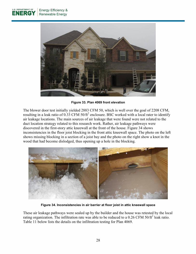
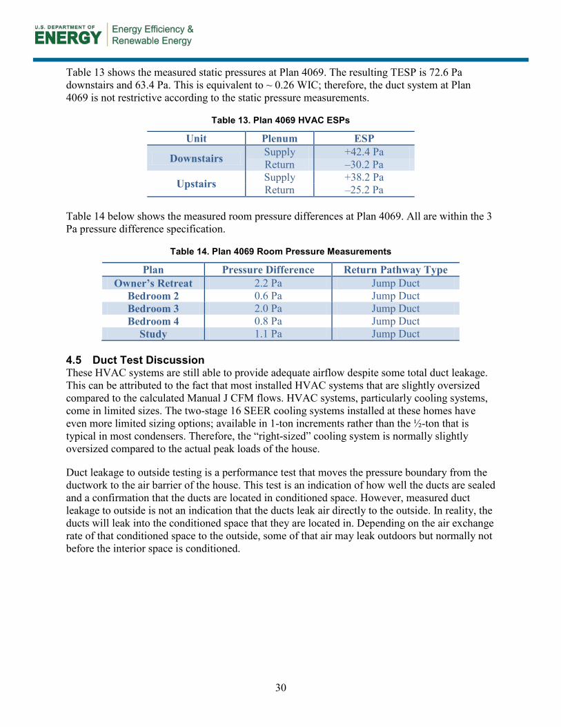
The blower door test initially yielded 2883 CFM 50, which is well over the goal of 2208 CFM, resulting in a leak ratio of 0.33 CFM 50/ft2 enclosure. BSC worked with a local rater to identify air leakage locations. The main sources of air leakage that were found were not related to the duct location strategy related to this research work. Rather, air leakage pathways were discovered in the first-story attic kneewall at the front of the house. Figure 34 shows inconsistencies in the floor joist blocking in the front attic kneewall space. The photo on the left shows missing blocking in a section of a joist bay and the photo on the right show a knot in the wood that had become dislodged, thus opening up a hole in the blocking.
Figure 34. Inconsistencies in air barrier at floor joist in attic kneewall space
These air leakage pathways were sealed up by the builder and the house was retested by the local rating organization. The infiltration rate was able to be reduced to a 0.26 CFM 50/ft2 leak ratio. Table 11 below lists the details on the infiltration testing for Plan 4069.

29
Table 11. Plan 4069 Infiltration Testing Results
Plan Test Description
CFM 50measured (CFM @ 50 Pa)
CFM 50goal (CFM @ 50 Pa)
ACH 50 (CFM 50/vol/h)
Leak Ratio (CFM 50/ft2)
4069 BSC initial test 2883 2208 4.4 0.33
4069 Follow-up after repair 2314 2208 3.5 0.26
Table 12 lists the details on the duct testing at Plan 4069. There are two HVAC systems at this house, an upstairs and downstairs unit. The total duct leakage for both the downstairs and upstairs units (112 and 95 CFM 25 respectively) constitutes 13% of the total 800 CFM of nominal cooling flow for both units. This meets the BSC recommended maximum 15% total duct leakage. The duct leak to outside was measured at 3 and 4% of nominal cooling flow and meets the 5% BSC requirement for duct leak to outside. An outside air duct was only installed on the downstairs furnace so no outside airflow measurement was available on the upstairs unit.
Table 12. Plan 4069 Duct Testing Results
Plan Duct25 Total (CFM @ 25 Pa)
Duct25 to Outside
(CFM @ 25 Pa)
Outside Duct Leakage
(5% Goal)
Outside Airflow (CFM)
4069 Downstairs Unit 112 25 3% of cooling flow 55
4069 Upstairs Unit 95 34 4% of cooling flow n/a
Figure 35 shows the measured flow versus designed flow plot. Flows that are below the specified CFM are no less than 15% below the Manual J8 calculated room CFM.
Figure 35. Plan 4069 design register flow versus measured register flow plot
0
20
40
60
80
100
120
140
0 20 40 60 80 100 120 140
Mea
sure
d Fl
ow (
CFM
)
Designed Flow (CFM)1st Floor Balometer Measurement in 2nd Stage Cooling
2nd Floor Balometer Measurement in 2nd Stage Cooling
30
Table 13 shows the measured static pressures at Plan 4069. The resulting TESP is 72.6 Pa downstairs and 63.4 Pa. This is equivalent to ~ 0.26 WIC; therefore, the duct system at Plan 4069 is not restrictive according to the static pressure measurements.
Table 13. Plan 4069 HVAC ESPs
Unit Plenum ESP
Downstairs Supply +42.4 Pa Return –30.2 Pa
Upstairs Supply +38.2 Pa Return –25.2 Pa
Table 14 below shows the measured room pressure differences at Plan 4069. All are within the 3 Pa pressure difference specification.
Table 14. Plan 4069 Room Pressure Measurements
Plan Pressure Difference Return Pathway Type Owner’s Retreat 2.2 Pa Jump Duct
Bedroom 2 0.6 Pa Jump Duct Bedroom 3 2.0 Pa Jump Duct Bedroom 4 0.8 Pa Jump Duct
Study 1.1 Pa Jump Duct 4.5 Duct Test Discussion These HVAC systems are still able to provide adequate airflow despite some total duct leakage. This can be attributed to the fact that most installed HVAC systems that are slightly oversized compared to the calculated Manual J CFM flows. HVAC systems, particularly cooling systems, come in limited sizes. The two-stage 16 SEER cooling systems installed at these homes have even more limited sizing options; available in 1-ton increments rather than the ½-ton that is typical in most condensers. Therefore, the “right-sized” cooling system is normally slightly oversized compared to the actual peak loads of the house.
Duct leakage to outside testing is a performance test that moves the pressure boundary from the ductwork to the air barrier of the house. This test is an indication of how well the ducts are sealed and a confirmation that the ducts are located in conditioned space. However, measured duct leakage to outside is not an indication that the ducts leak air directly to the outside. In reality, the ducts will leak into the conditioned space that they are located in. Depending on the air exchange rate of that conditioned space to the outside, some of that air may leak outdoors but normally not before the interior space is conditioned.

31
5 Duct Design Cost Analysis
The costs for moving the HVAC system into conditioned space can be broken down into two main categories: Additional enclosure costs and additional mechanical costs.
Note on air conditioner efficiency: The air conditioners in these homes were upgraded from a single-stage 15 SEER unit to a two-stage 16 SEER system in order to improve the energy performance of the homes to meet BA targets. This upgrade is not relevant to the primary research goal of locating ductwork in conditioned space via an economical methodology; therefore, the HVAC costs for this section assume no change in air conditioner efficiency. Note that the 96% sealed combustion furnaces at the three research homes are typical for DWH construction.
In addition to the air conditioner efficiency upgrade, non-related enclosure upgrades (e.g., increasing ceiling insulation from R-38 to R-50) were also not included in this section.
The duct design cost analysis will show that this strategy is more economical in existing floor plans versus the popular strategy of constructing an unvented cathedralized attic. However, it does not appear to be as cost effective as the cost of moving ducts to conditioned space by developing new plans from scratch that will allow the designer more flexibility in making enough room to avoid the costly coffers up into the attic space. This is discussed more in the conclusion.
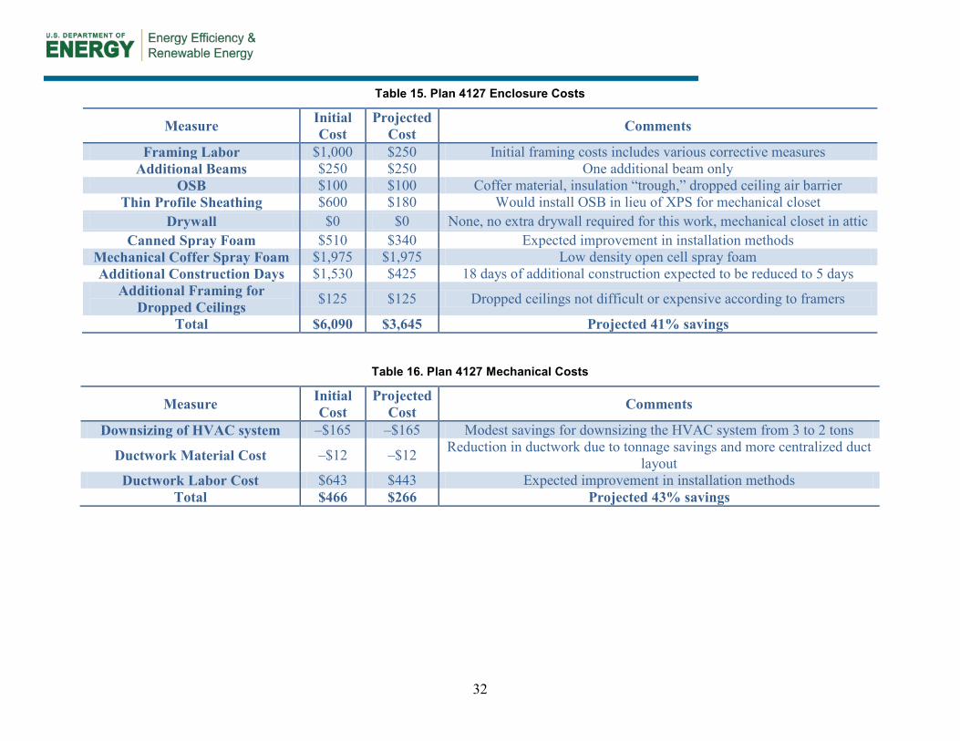
5.1 Plan 4127 Table 15 shows the additional enclosure costs related to moving the ductwork inside conditioned space. The Initial Cost column indicates the actual cost to implement each measure at each house. The Projected Costs correspond to estimated future costs for each measure and include improvements in the implementation of said measure. DWH expects a 41% savings in enclosure related costs should this duct design strategy be implemented in a future Plan 4127.
Table 16 below shows the additional mechanical costs. A reduction in air conditioner tonnage was possible due to the relocation of the entire HVAC system into conditioned space; therefore this reduction in cost is included here. Overall, the HVAC contractor expects a 43% reduction in savings should this duct design strategy be implemented in a future Plan 4127.
The total projected cost for both the enclosure and mechanical measures at Plan 4127 is $3911. BEopt predicts $92 savings in annual utility costs when moving the ductwork into conditioned space (assuming R-8 ducts in the vented attic space with 15% total duct leakage). This results in a payback period of around 42 years for this measure. The other two plans yield very similar paybacks.
32
Table 15. Plan 4127 Enclosure Costs
Measure Initial Cost
Projected Cost Comments
Framing Labor $1,000 $250 Initial framing costs includes various corrective measures Additional Beams $250 $250 One additional beam only
OSB $100 $100 Coffer material, insulation “trough,” dropped ceiling air barrier Thin Profile Sheathing $600 $180 Would install OSB in lieu of XPS for mechanical closet
Drywall $0 $0 None, no extra drywall required for this work, mechanical closet in attic Canned Spray Foam $510 $340 Expected improvement in installation methods
Mechanical Coffer Spray Foam $1,975 $1,975 Low density open cell spray foam Additional Construction Days $1,530 $425 18 days of additional construction expected to be reduced to 5 days
Additional Framing for Dropped Ceilings $125 $125 Dropped ceilings not difficult or expensive according to framers
Total $6,090 $3,645 Projected 41% savings
Table 16. Plan 4127 Mechanical Costs
Measure Initial Cost
Projected Cost Comments
Downsizing of HVAC system –$165 –$165 Modest savings for downsizing the HVAC system from 3 to 2 tons
Ductwork Material Cost –$12 –$12 Reduction in ductwork due to tonnage savings and more centralized duct layout
Ductwork Labor Cost $643 $443 Expected improvement in installation methods Total $466 $266 Projected 43% savings

33
5.2 Plan 4128 Table 17 shows the enclosure related costs for Plan 4128.
Table 18 shows the additional mechanical costs for Plan 4128. The projected savings for Plan 4128 (63%) is quite higher than Plan 4127 (43%), and this is primarily due to Plan 4128 having a single HVAC system that serves both the first and second floors. The complexities associated with ducting both floors to a single furnace led to a higher initial cost than the other houses.

34
Table 17. Plan 4128 Enclosure Costs
Measure Initial Cost
Projected Cost Comments
Framing Labor $1,000 $250 Initial framing costs includes various corrective measures Additional Beams $250 $250 One additional beam only
OSB $100 $100 Coffer material, insulation “trough,” dropped ceiling air barrier Thin Profile Sheathing $1,000 $300 Would install OSB in lieu of XPS for mechanical closet
Drywall $0 $0 None, no extra drywall required for this work Canned Spray Foam $480 $240 Expected improvement in installation methods
Mechanical Coffer Spray Foam $1,771 $1,771 Low density open cell spray foam Additional Construction Days $1,530 $425 18 days of additional construction expected to be reduced to 5 days
Additional Framing for Dropped Ceilings $125 $125 Dropped ceilings not difficult or expensive according to framers
Total $6,256 $3,461 Projected 45% savings
Table 18. Plan 4128 Mechanical Costs
Measure Initial Cost
Projected Cost
Comments
Downsizing of HVAC system –$135 –$135 Modest savings for downsizing the HVAC system from 3 to 2.5 tons Ductwork Material Cost –$109 –$109 Reduction in ductwork due to tonnage savings and more centralized duct
layout Ductwork Labor Cost $1,224 $663 Expected improvement in installation methods
Total $980 $419 Projected 63% savings
35
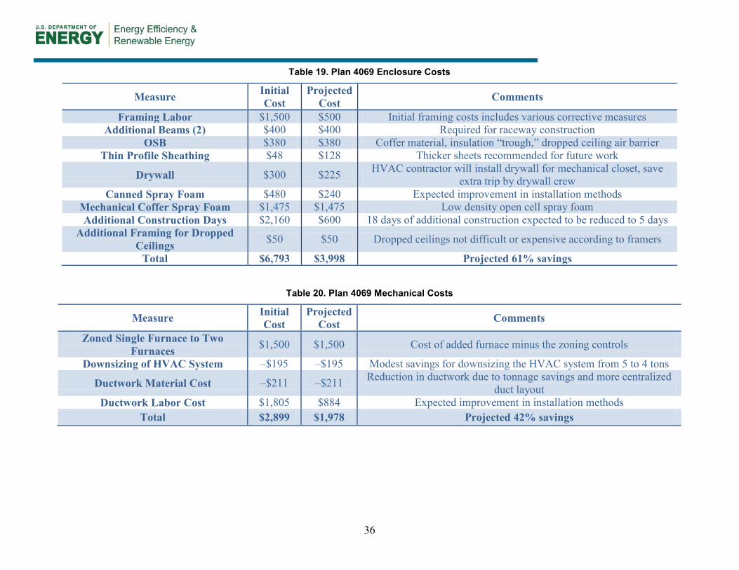
5.3 Plan 4069 Table 19 shows the enclosure related costs for Plan 4069. One item of note is that additional drywall was required for the second mechanical closet (due to the change from one to two HVAC systems).
Table 20 shows the additional mechanical costs for Plan 4069. Included in these costs is the shift from one zoned HVAC system to two separate HVAC systems. The projected savings for Plan 4069 (42%) is very similar to Plan 4127 (43%). The two HVAC systems at Plan 4069 essentially create two single-story floor plans, with separate HVAC systems, stacked on one another.
5.4 Cost Analysis Discussion The mechanical coffer constitutes a major portion of the costs for moving the HVAC system inside conditioned space however, note that the builder believes that the homeowner greatly values the living space that is saved by not having the furnace in a closet in the main living space.
The payback for these homes is high however, ducts inside conditioned space yield significant predicted improvements in efficiency through other metrics. For example, BEopt predicts an overall annual source energy improvement of 5%–6% when moving ductwork inside conditioned space. Additionally, REM/Rate predicts a reduction of around 4–5 HERS Index points for the same measure. These are very significant improvements in predicted performance, as most upgrades typically impact the HERS Index in the range of 1–3 points. Please refer to Section 7 for a parametric HERS Index analysis on one of the floor plans. Also, energy codes such as the 2012 IECC and efficiently programs such as the DOE Challenge Home program require ducts in conditioned space, regardless of the economics. Therefore, moving ducts inside conditioned space is not an elective upgrade for this builder and any other affected by these increasingly stringent codes and rating programs.
36
Table 19. Plan 4069 Enclosure Costs
Measure Initial Cost
Projected Cost Comments
Framing Labor $1,500 $500 Initial framing costs includes various corrective measures Additional Beams (2) $400 $400 Required for raceway construction
OSB $380 $380 Coffer material, insulation “trough,” dropped ceiling air barrier Thin Profile Sheathing $48 $128 Thicker sheets recommended for future work
Drywall $300 $225 HVAC contractor will install drywall for mechanical closet, save extra trip by drywall crew
Canned Spray Foam $480 $240 Expected improvement in installation methods Mechanical Coffer Spray Foam $1,475 $1,475 Low density open cell spray foam Additional Construction Days $2,160 $600 18 days of additional construction expected to be reduced to 5 days
Additional Framing for Dropped Ceilings $50 $50 Dropped ceilings not difficult or expensive according to framers
Total $6,793 $3,998 Projected 61% savings
Table 20. Plan 4069 Mechanical Costs
Measure Initial Cost
Projected Cost Comments
Zoned Single Furnace to Two Furnaces $1,500 $1,500 Cost of added furnace minus the zoning controls
Downsizing of HVAC System –$195 –$195 Modest savings for downsizing the HVAC system from 5 to 4 tons
Ductwork Material Cost –$211 –$211 Reduction in ductwork due to tonnage savings and more centralized duct layout
Ductwork Labor Cost $1,805 $884 Expected improvement in installation methods Total $2,899 $1,978 Projected 42% savings

37
6 Code Compliance Analysis
DWH expressed a desire to better understand the implications of the 2015 IECC code changes with respect to energy performance. BSC speculates that the energy performance threshold for the 2015 IECC will be around 50% of the 2006 IECC provisional mandate. Note that IECC compliance is currently calculated for heating, cooling, and hot water only. Therefore, this analysis is to show how a DWH floor plan can save 50% in heating, cooling, and hot water energy use compared to the IECC 2006. The HERS Index is included in this analysis as an additional metric, as it is useful to raters and builders.
Plan 4127 was chosen for this analysis as it is the smallest floor plan of the three research houses and therefore is the most conservative. REM/Rate version 14.0 was utilized for this work. This software is produced by Architectural Energy Corporation and is one of the most recognizable residential modeling software packages in the industry. The HERS rating organization for DWH – Houston division uses REM/Rate; therefore, this work and methodology are easily transferrable to DWH and its contractors.
The upgrades considered for this analysis were selected in a collaborative effort with BSC and DWH, as DWH best understands what upgrades are easily integrated into its production environment versus others. Therefore, this is not a full parametric analysis in the sense that all possible upgrades are considered. Rather, many upgrades options were eliminated through direct cooperation with the builder such that the end result represents the most economical upgrade package for DWH and the easiest to integrate into current production.
The starting point for the analysis is to begin with Plan 4127 with DWH typical characteristics. This includes:
• R-38 ceiling
• 2 × 6 walls with R-3 XPS
• Vinyl windows U=~0.29, SHGC = ~0.22
• Infiltration rate = 0.25 leak ratio (CFM 50/ft2 enclosure)
• 96% AFUE furnace and R-6 ductwork in vented attic
• 15 SEER air conditioner
• Gas tank water heater EF = 0.62
• CFIS ventilation with 33% duty cycle fan cycling control.
Plan 4127 with typical building characteristics saves 39% versus the 2006 IECC and scores 66 on the HERS Index.
Table 21 outlines the upgrades implemented for each compliance run in this analysis. Table 22 shows the pathway for Plan 4127 to meet at least 50% energy savings versus the 2006 IECC using the current methodology of assessing only heating, cooling and hot water energy use. Note that each run is cumulative. The organization of this chart has been kept like the output from the REM/Rate report module for the sake of consistency.

38
Referring to Table 22 the single largest contributor to energy savings is Run 1: Moving the furnace and ductwork inside conditioned space, which results in 44% energy savings versus the 2006 IECC and a HERS Index of 62. Runs 2–8 apply upgrades that DWH prefers to consider for achieving 50% savings versus the 2006 IECC. Run 8 (100% compact fluorescent and ENERGY STAR® appliances) is an unnecessary step for achieving 50% energy savings versus the 2006 IECC, as only heating, cooling and hot water energy is considered. However, the impact of this improvement on the HERS Index was of interest to the group as DWH estimated the 2015 IECC code mandate to be equivalent to a HERS Index in the low 50s. It is also expected that a similar HERS score must be achieved to qualify for the DOE Challenge Home criteria.

39
Table 21. Plan 4127 IECC 2006 Compliance Analysis Specifications
Run Description of Specification Upgrade Increase in
% Savings Versus IECC 2006
Reduction in HERS
Index Run 1 Furnace and ductwork moved from the vented attic to conditioned space 5 4 Run 2 Infiltration reduced from 0.25 to 0.20 CFM 50/ft2 enclosure 2 1 Run 3 Wall insulating sheathing R-value increased from R-3 to R-5 1 0 Run 4 Ceiling insulation increased from R-38 to R-50 0 1
Run 5 Air conditioner upgraded from 15 SEER single-stage to 16 SEER two-stage condenser 2 1
Run 6 Water heater upgraded from 0.62 EF tank to 0.82 EF tankless water heater 4 3
Run 7 Fluorescent lights increased from 60% to 100% and appliances upgraded to ENERGY STAR –1 5

40
Table 22. Plan 4127 IECC 2006 Energy Cost Compliance Chart
Typical DWH Design HERS 66 Run 1: HVAC Inside HERS 62 Energy Cost Compliance 2006 IECC As Designed % 2006 IECC As Designed %
Heating 228 97 57% 230 93 60% Cooling 382 239 37% 381 209 45%
Water Heating 110 103 6% 110 103 6% Sub Total—Used for Compliance 720 439 39% 721 405 44%
Run 2: 0.20 Leak Ratio HERS 61 Run 3: 2x6 OVE + R-5 HERS 61 Energy Cost Compliance 2006 IECC As Designed % 2006 IECC As Designed %
Heating 230 84 63% 230 79 66% Cooling 381 205 46% 381 202 47%
Water Heating 110 103 6% 110 103 6% Sub Total—Used for Compliance 721 392 46% 721 384 47%
Run 4: R-50 attic HERS 60 Run 5: 16 SEER HERS 59 Heating 230 77 67% 230 75 67% Cooling 381 201 47% 381 191 50%
Water Heating 110 103 6% 110 103 6% Sub Total—Used for Compliance 721 381 47% 721 369 49%
Run 6: 0.82 EF Hot Water HERS 56 Run 7: 100% CFL/ES Apps HERS 51 Heating 230 75 67% 237 80 66% Cooling 381 191 50% 374 184 51%
Water Heating 108 75 31% 115 81 30% Sub Total—Used for Compliance 719 341 53% 726 345 52%

41
7 Conclusions
This work with DWH served to answer the following research questions.
1. What is the most cost-effective, best-performing, and most easily replicable method of locating ducts inside conditioned space for a hot-humid production home builder that constructs one- and two-story single-family detached residences?
DWH believes that this developed strategy for locating ductwork in conditioned space has potential as an economical method for increasing the energy efficiency of its existing production homes. However, the builder does believe that developing new floor plans from scratch will allow for a more economical integration of ductwork inside conditioned space. Most notably, this systems engineering approach could preclude the need for mechanical coffers into the attic space and could allow for the sole use of dropped ceilings for locating ductwork.
DWH has provided positive feedback on the duct designs that were implemented at these three research homes. The development of a design for duct coffers in the attic space allows DWH to embrace the strategy of locating ductwork in conditioned space in its existing housing stock, without having to rely solely on dropped ceilings. The builder does recognize that a full series of dropped ceilings, without any coffers, would be the most economical strategy for locating ducts. However, the builder perceives this design as having a negative impact on aesthetics and could not be attractive to its customer base. This is one of the more important developments in this research work, as DWH (and its customers) greatly value full ceiling height in the majority of spaces and wish to avoid dropped ceilings as much as possible. The main contribution of this research was to provide a working alternative for builders who wish to move their HVAC systems into conditioned spaces without extended dropped ceilings plus a mechanical closet, or converting to a full unvented cathedralized attic.
DWH is confident that the costs for moving ducts into conditioned space can be reduced in future homes, as shown in the cost analysis section. However, this methodology is still considered a “retrofit” in that existing floor plans have to be altered to allow for the implementation of this duct strategy. DWH has expressed interest in working to develop new floor plans that more seamlessly integrate the HVAC system as a part of conditioned space. This work would require more upfront collaboration between the architect and HVAC contractor but could yield a more cost-effective design. It is possible that this design may not require coffers but rather the ducts can be completely located in dropped ceilings in sensible locations. Cost estimates are not available at this time for this integrative approach, and more research is needed to fully quantify the cost of moving ducts into conditioned space by developing new plans from scratch with the architect and HVAC contractor openly collaborating on an efficient duct layout. It is important to note that the changes in code requirements and the criteria of various energy efficiency programs are forcing DWH to quickly integrate ducts into conditioned space in its existing floor plan portfolio. This research work identified the most economical strategy to move ductwork into conditioned space for existing floor plans. DWH does not have the resources to develop new floor plans en masse with ducts inside conditioned space, although this design strategy does represent the most cost-effective approach to moving the HVAC system within conditioned space.

42
Each house was commissioned by BSC and was found to conform to BA specifications. The average infiltration rate for these homes was slightly lower than what is typically constructed by DWH, and DWH maintains that this can be improved on in future homes. No degradation in performance was observed either in the enclosure or mechanical systems during commissioning. All ductwork is installed correctly and proper airflow is being supplied to all the rooms via the mechanical system. Duct leaks to outside measurements have improved dramatically compared to the previous strategy of ducts in the vented attic.
The duct design strategy employed resulted in significant energy savings toward the goal of achieving 50% energy savings versus the 2006 IECC. Moving the HVAC system inside conditioned space saves around 4%–5% in source energy use and can reduce the HERS Index by around 4 points. The costs for implementing this duct design strategy on the three research homes was in the range of $6,000–$10,000; however, the builder expects that this figure can improve in future homes to around $4,000–$6,000. This is more affordable compared to the popular strategy of constructing an unvented cathedralized attic with spray polyurethane foam, which for these plans could cost in the range of $10,000–$15,000, according to DWH.
2. What is a cost-effective and practical method of achieving 50% source energy savings versus the 2006 IECC for a hot-humid production builder?
BSC speculates that the 2015 IECC will mandate an energy efficiency threshold equal to 50% energy savings versus the 2006 IECC. Analysis was performed with REM/Rate to identify the most economical upgrades to achieve 50% savings versus the IECC 2006. Moving the HVAC system to conditioned space was a key improvement for this analysis and in fact constituted the largest increase in efficiency compared to any other individual upgrade. In addition to moving the HVAC system to conditioned space, the builder identified upgrades that are economical to implement in its production environment. This includes upgrades to the wall and ceiling insulation, as well as increases in air conditioner and water heater efficiencies.
3. How accurate are the pre-construction whole-house cost estimates compared to confirmed post-construction actual costs?
The initial cost estimates for moving the HVAC system to inside space were close to the post-construction confirmed costs. DWH does estimate that it can save around 40%–50% in installed costs for both the mechanical and enclosure components of the duct design strategy. This translates to around $2,000–$4,000 in savings per house once the builder and HVAC contractor optimize this strategy.
The predicted cost estimates for the other mechanical and enclosure upgrades unrelated to the duct design strategy are very close to the confirmed costs, as this production builder has extensive experience in costing various options for its product.

43
References
Andrews, J. 2003. “Residential Duct Diagnostics and Repair.” Air Conditioning Contractors of America.
ASTM Standard E779. (2003a), Standard Test Method for Determining Air Leakage Rate by Fan Pressurization. West Conshohocken, PA, ASTM International.
ASTM Standard E1554. (2003b), Standard Test Methods for Determining External Air Leakage of Air Distribution Systems by Fan Pressurization. West Conshohocken, PA, ASTM International.
Bailes III, A. (2012). “Efficiency Programs Struggle to Stay Ahead of Energy Codes.” Green Building Advisor, www.greenbuildingadvisor.com/blogs/dept/building-science/efficiency-programs-struggle-stay-ahead-energy-codes. Accessed June 6, 2012.
Baker, P. (2006). “RR-0604: Incorporating Insulating Sheathing into the Design of the Thermal and Moisture Management System of the Building Enclosure.” Building Science Corporation, www.buildingscience.com/documents/reports/rr-0604-incorporating-insulating-sheathing-into-design-of-thermal-and-moisture-management-system-of-building-enclosure/. Accessed June 6, 2012.
Burdick, A. (2011). “Advanced Strategy Guideline: Air Distribution Basics and Duct Design” DOE/GO-102011-3461. Pittsburgh, PA: IBACOS.
BSC (2007). “Guide to Insulating Sheathing.” Building Science Corporation, www.buildingscience.com/documents/guides-and-manuals/gm-guide-insulating-sheathing/. Accessed June 6, 2012.
BSC (2009). “Info-201: Common Advanced Framing Details.” Building Science Corporation, www.buildingscience.com/documents/information-sheets/2-framing/information-sheet-common-advanced-framing-details/. Accessed June 6, 2012.
BSC (2010). “Designs that Work - Cold Climate: Habitat for Humanity High R-Value Prototype.” Building Science Corporation, www.buildingscience.com/documents/case-studies/cs-ma-westford-hfh/. Accessed June 6, 2012.
Chasar, D.; Withers, C. (2013). “Measured Cooling Performance and Potential for Buried Duct Condensation in a 1991 Central Florida Retrofit Home” FSEC-CR-1946-13. Cocoa, FL: FSEC.
Hendron, R.; Anderson, R.; Barley, D.; Rudd, A.; Townsend, A.; Hancock, E. (2008). “Field Test of Room-to-Room Distribution of Outside Air with Two Residential Ventilation Systems.” Prepared for ASHRAE IAQ 2007 Baltimore, Maryland October 15–17, 2007. NREL/CP-550-41210. Golden, CO: National Renewable Energy Laboratory, 19 pp.
44
Griffiths, D.; Zuluaga, M.; Springer, D.; Aldrich, R. (2004). “Insulation Buried Attic Ducts: Analysis and Field Evaluation Findings.” In Proceedings of the 2004 ACEEE Summer Study on Energy Efficiency in Buildings. Washington, DC: American Council for an Energy-Efficient Economy.
ICC (2012). “International Residential Code for One and Two –Family Dwellings”. International Code Council.
Lstiburek, J.W (2005). Builder’s Guide to Hot-Humid Climates. Westford, MA: Building Science Press.
Lstiburek, J.W.; Grin, A. (2010). “RR-1004: Building America Special Research Project—Advanced Framing Deployment.” Building Science Corporation, www.buildingscience.com/documents/reports/rr-1004-ba-special-research-advanced-framing-deployment/. Accessed June 6, 2012.
Lubliner, M.; Kerr, R.; Gordon, A.; Murray, C. (2008). “Moving Ducts Inside: Big Builders, Scientists Find Common Ground.” In Proceedings of the 2008 ACEEE Summer Study on Energy Efficiency in Buildings. Washington, DC: American Council for an Energy-Efficient Economy.
Rudd, A. (2008). “RR-0304: Central Fan Integrated Supply Ventilation—The Basics.” Building Science Corporation, www.buildingscience.com/documents/reports/rr-0304-central-fan-integrated-supply-ventilation-the-basics/. Accessed June 6, 2012.
Rudd, A. (2006). “Design Process for Sizing: Cooling and Heating System Capacity, Room Air Flows, Trunk and Runout Ducts, and Transfer Air Ducts.” Building Science Corporation, www.buildingscience.com/documents/guides-and-manuals/gm-system-sizing-pro/view. Accessed April 4, 2013.

45
Appendix
Whole-House Energy Analysis BEopt software was utilized to calculate the annual source energy savings versus the BA Benchmark. The BEopt software includes an optimization capability that uses user-supplied cost data and energy use information for a specified set of energy-saving measures to determine combinations of measures that are optimal or near optimal in terms of cost effectiveness. BEopt uses a sequential searching technique so that not every possible combination of options is simulated. BSC compiled cost figures from DWH and updated the BEopt Cost Library.
Table 23 lists the whole unit, new construction, cost data provided by DWH for the characteristics implemented in these three research homes.
Table 23. DWH Cost Data for BEopt Analysis
Component Cost R-50 Blown Fiberglass Ceiling Insulation $0.78/ft2
2 × 6 R19 Fiberglass Batts + ¾-in. XPS $3.76/ft2 R-30 Batts Cantilever Floor $0.72/ft2
Windows (Double Glazed, Argon Filled, U = 0.29, SHGC = 0.22) $25.36/ft2 96% AFUE Furnace $2,365
16 SEER Two-Stage Air Conditioner $3,420 Fan Cycling Controller With Mechanical Damper $345
The following sections list the specific BEopt output for each of the three floor plans. The BEopt parametric function was utilized for each plan in establishing the most cost effective building characteristics out of the options that were discussed with DWH.
Plan 4127 BEopt Figure 36 compares the predicted source energy use to the BA Benchmark, as calculated by BEopt, and is broken down into various end uses. Plan 4127 is estimated to save 36% in source energy use versus the BA Benchmark. This is equivalent to around 56.3 MBtu/yr.

46
Figure 36. Plan 4127 BEopt source energy savings versus the BA Benchmark—end use breakdown
Figure 37 is the BEopt optimization graph that plots the various combinations of characteristic that were calculated. The circled point for the technology package in the swoosh curve is the proposed technology package. This point has the lowest annualized energy related costs and is represented as the most cost-optimized configuration for the options studied.
Figure 37. Plan 4127 BEopt parametric graph

47
Plan 4128 BEopt Figure 38 compares the predicted source energy use to the BA Benchmark, as calculated by BEopt, and is broken down into various end uses. Plan 4128 is estimated to save 32% in source energy use versus the BA Benchmark. This is equivalent to around 52.3 MBtu/yr.
Figure 38. Plan 4128 BEopt source energy savings versus the BA Benchmark—end use breakdown
Figure 39 is the BEopt optimization graph that plots the various combinations of characteristic that were calculated. The circled point for the technology package in the swoosh curve is the proposed technology package. This point has the lowest annualized energy-related costs and is represented as the most cost-optimized configuration for the options studied.
Figure 39. Plan 4128 BEopt parametric graph

48
Plan 4069 BEopt Figure 40 compares the predicted source energy use to the BA Benchmark, as calculated by BEopt, and is broken down into various end uses. Plan 4128 is estimated to save 27% in source energy use versus the BA Benchmark. This is equivalent to around 59.3 MBtu/yr.
Figure 40. Plan 4069 BEopt source energy savings versus the BA Benchmark—end use breakdown
Figure 41 is the BEopt optimization graph that plots the various combinations of characteristics that were calculated. The circled point for the technology package in the swoosh curve is the proposed technology package. This point has the lowest annualized energy-related costs and is represented as the most cost-optimized configuration for the options studied.
Figure 41. Plan 4069 BEopt parametric graph duct layouts

49
Plan 4127
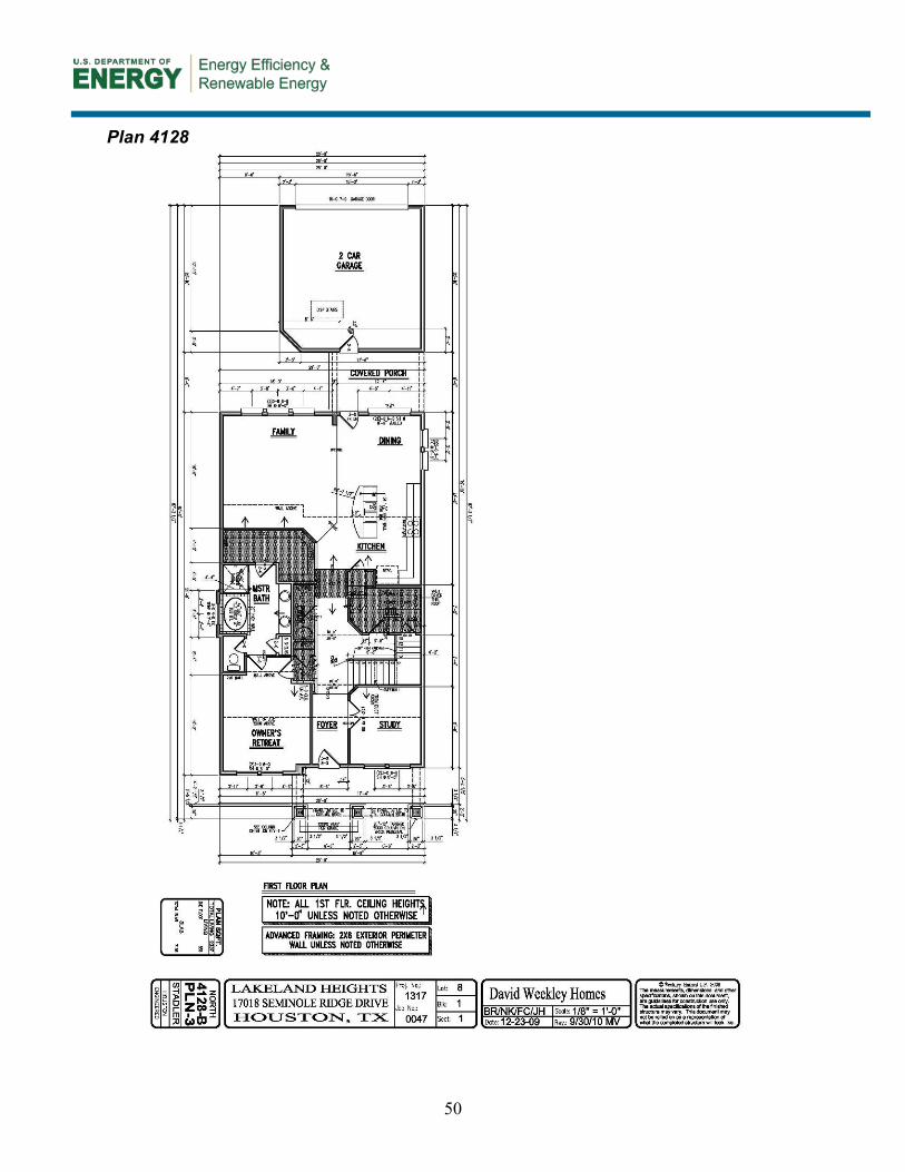
50
Plan 4128

51

52
Plan 4069

53

54

55

buildingamerica.gov
DOE/GO-102014-4364 ▪ March 2014
Printed with a renewable-source ink on paper containing at least 50% wastepaper, including 10% post-consumer waste.