heating and air conditioning - colorado4wheel.com€¦ · heating and air conditioning ......
TRANSCRIPT
D
D
WJ HEATING AND AIR CONDITIONING 24 - 1
HEATING AND AIR CONDITIONING
TABLE OF CONTENTS
page page
ESCRIPTION AND OPERATIONACCUMULATOR . . . . . . . . . . . . . . . . . . . . . . . . . . 2BLOWER MOTOR . . . . . . . . . . . . . . . . . . . . . . . . . 2BLOWER MOTOR CONTROLLER . . . . . . . . . . . . . 2BLOWER MOTOR RESISTOR . . . . . . . . . . . . . . . . 3BLOWER MOTOR SWITCH. . . . . . . . . . . . . . . . . . 3COMPRESSOR . . . . . . . . . . . . . . . . . . . . . . . . . . . 3COMPRESSOR CLUTCH . . . . . . . . . . . . . . . . . . . . 3COMPRESSOR CLUTCH RELAY . . . . . . . . . . . . . . 4CONDENSER. . . . . . . . . . . . . . . . . . . . . . . . . . . . . 4EVAPORATOR COIL . . . . . . . . . . . . . . . . . . . . . . . 4FIXED ORIFICE TUBE . . . . . . . . . . . . . . . . . . . . . . 5HEATER CORE . . . . . . . . . . . . . . . . . . . . . . . . . . . 5HEATER AND AIR CONDITIONER. . . . . . . . . . . . . 5HEATER AND AIR CONDITIONER CONTROL . . . . 6HIGH PRESSURE RELIEF VALVE . . . . . . . . . . . . . 7HIGH PRESSURE SWITCH . . . . . . . . . . . . . . . . . . 7INFRARED TEMPERATURE SENSOR . . . . . . . . . . 7LOW PRESSURE SWITCH . . . . . . . . . . . . . . . . . . 8REFRIGERANT . . . . . . . . . . . . . . . . . . . . . . . . . . . 8REFRIGERANT LINES . . . . . . . . . . . . . . . . . . . . . . 8REFRIGERANT OIL . . . . . . . . . . . . . . . . . . . . . . . . 9REFRIGERANT SYSTEM SERVICE PORTS. . . . . . 9VACUUM CHECK VALVE . . . . . . . . . . . . . . . . . . . . 9VACUUM RESERVOIR . . . . . . . . . . . . . . . . . . . . . 9IAGNOSIS AND TESTINGA/C PERFORMANCE . . . . . . . . . . . . . . . . . . . . . . 10AUTOMATIC ZONE CONTROL SYSTEM . . . . . . . 13BLOWER MOTOR . . . . . . . . . . . . . . . . . . . . . . . . 22BLOWER MOTOR RESISTOR . . . . . . . . . . . . . . . 22BLOWER MOTOR SWITCH. . . . . . . . . . . . . . . . . 22COMPRESSOR . . . . . . . . . . . . . . . . . . . . . . . . . . 23COMPRESSOR CLUTCH COIL . . . . . . . . . . . . . . 23COMPRESSOR CLUTCH RELAY . . . . . . . . . . . . . 24HEATER PERFORMANCE . . . . . . . . . . . . . . . . . . 25HIGH PRESSURE SWITCH . . . . . . . . . . . . . . . . . 25LOW PRESSURE SWITCH . . . . . . . . . . . . . . . . . 25REFRIGERANT SYSTEM LEAKS . . . . . . . . . . . . . 26VACUUM SYSTEM . . . . . . . . . . . . . . . . . . . . . . . 26
SERVICE PROCEDURESREFRIGERANT OIL LEVEL . . . . . . . . . . . . . . . . . 28REFRIGERANT RECOVERY. . . . . . . . . . . . . . . . . 29REFRIGERANT SYSTEM CHARGE . . . . . . . . . . . 29REFRIGERANT SYSTEM EVACUATE. . . . . . . . . . 30REFRIGERANT SYSTEM SERVICE
EQUIPMENT. . . . . . . . . . . . . . . . . . . . . . . . . . . 30REMOVAL AND INSTALLATION
SERVICE WARNINGS AND PRECAUTIONS . . . . 31ACCUMULATOR . . . . . . . . . . . . . . . . . . . . . . . . . 33BLEND-AIR DOOR(S) . . . . . . . . . . . . . . . . . . . . . 34BLOWER MOTOR . . . . . . . . . . . . . . . . . . . . . . . . 36BLOWER MOTOR RESISTOR AND
CONTROLLER . . . . . . . . . . . . . . . . . . . . . . . . . 37COMPRESSOR . . . . . . . . . . . . . . . . . . . . . . . . . . 38COMPRESSOR CLUTCH . . . . . . . . . . . . . . . . . . . 39COMPRESSOR CLUTCH RELAY . . . . . . . . . . . . . 41CONDENSER. . . . . . . . . . . . . . . . . . . . . . . . . . . . 42DISCHARGE LINE . . . . . . . . . . . . . . . . . . . . . . . . 42DUCTS AND OUTLETS . . . . . . . . . . . . . . . . . . . . 44EVAPORATOR COIL . . . . . . . . . . . . . . . . . . . . . . 46HEAT/DEFROST DOOR . . . . . . . . . . . . . . . . . . . . 47HEATER-A/C CONTROL . . . . . . . . . . . . . . . . . . . 49HEATER-A/C HOUSING. . . . . . . . . . . . . . . . . . . . 49HEATER CORE AND TUBES . . . . . . . . . . . . . . . . 51HIGH PRESSURE RELIEF VALVE . . . . . . . . . . . . 52HIGH PRESSURE SWITCH . . . . . . . . . . . . . . . . . 53LIQUID LINE . . . . . . . . . . . . . . . . . . . . . . . . . . . . 54LOW PRESSURE CYCLING CLUTCH SWITCH . . 54MODE DOOR ACTUATORS . . . . . . . . . . . . . . . . . 55PANEL/DEFROST DOOR AND LEVER. . . . . . . . . 57PANEL OUTLET DOOR . . . . . . . . . . . . . . . . . . . . 58RECIRCULATION AIR DOOR . . . . . . . . . . . . . . . 59VACUUM CHECK VALVE . . . . . . . . . . . . . . . . . . . 59VACUUM RESERVOIR . . . . . . . . . . . . . . . . . . . . 60VARIABLE ORIFICE VALVE . . . . . . . . . . . . . . . . . 60
SPECIFICATIONSA/C APPLICATION TABLE . . . . . . . . . . . . . . . . . . 60
D
A
D
pt
O
lucmat
24 - 2 HEATING AND AIR CONDITIONING WJ
ESCRIPTION AND OPERATION
CCUMULATOR
ESCRIPTIONThe accumulator is mounted in the engine com-
artment between the evaporator coil outlet tube andhe compressor inlet.
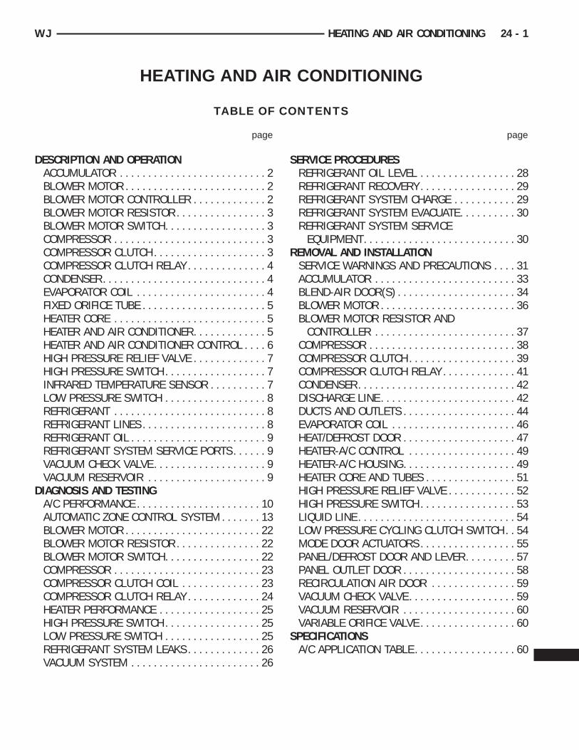
PERATIONRefrigerant enters the accumulator canister as a
ow pressure vapor through the inlet tube. Any liq-id, oil-laden refrigerant falls to the bottom of theanister, which acts as a separator. A desiccant bag isounted inside the accumulator canister to absorb
ny moisture which may have entered and becomerapped within the refrigerant system (Fig. 1).
Fig. 1 Accumulator - Typical1 – LOW PRESSURE CYCLING CLUTCH SWITCH2 – PRESSURE SWITCH FITTING3 – OUTLET TO COMPRESSOR4 – ANTI-SIPHON HOLE5 – DESICCANT BAG6 – OIL RETURN ORIFICE FILTER7 – VAPOR RETURN TUBE8 – ACCUMULATOR DOME9 – O-RING SEAL10 – INLET FROM EVAPORATOR
BLOWER MOTOR
DESCRIPTIONThe blower motor and blower wheel are located in
the passenger side end of the heater-A/C housing,below the glove box module. The blower motor con-trols the velocity of the air flowing through the heat-er-A/C housing by spinning a squirrel cage-typeblower wheel within the housing at the selectedspeed. The blower motor and blower wheel can beserviced from the passenger compartment side of thehousing.
OPERATIONThe blower motor will only operate when the igni-
tion switch is in the On position, and the heater-A/Cmode control switch is in any position, except Off.The blower motor circuit is protected by a fuse in thejunction block. On models with the standard manualtemperature control system, the blower motor speedis controlled by regulating the battery feed throughthe blower motor switch and the blower motor resis-tor. On models with the optional Automatic ZoneControl (AZC) system, the blower motor speed is con-trolled by using Pulse Width Modulation (PWM). Thepower module adjusts the battery feed voltage to theblower motor, based upon an input from the blowermotor switch, through the AZC control module. Pulsewidth modulation of blower power allows the blowerto operate at any speed from stationary, to full speed.
The blower motor and blower motor wheel cannotbe repaired, and if faulty or damaged, they must bereplaced. The blower motor and blower wheel areeach serviced separately.
BLOWER MOTOR CONTROLLER
DESCRIPTIONModels equipped with the optional Automatic Zone
Control (AZC) system have a blower motor controller(power module). The controller allows the selection ofalmost infinitely variable blower motor speeds. Thecontroller is mounted to the heater-A/C housing,under the instrument panel and just inboard of theblower motor, in the same location used for theblower motor resistor on manual temperature controlsystems. It can be accessed without removing anyother components.
OPERATIONThe blower motor controller output to the blower
motor can be adjusted by the blower motor speedswitch knob on the AZC heater-A/C control panel, orit can be adjusted automatically by the logic circuitryand programming of the AZC control module. Ineither case, the AZC control module sends the correct
pos
a
B
D
cbhjf
O
wmtbt
ptsbtttb
i
B
D
rhtsoatCtb
O
bbmt
WJ HEATING AND AIR CONDITIONING 24 - 3
DESCRIPTION AND OPERATION (Continued)
ulse width modulated signal to the power module tobtain the selected or programmed blower motorpeed.The blower motor controller cannot be repaired
nd, if faulty or damaged, it must be replaced.
LOWER MOTOR RESISTOR
ESCRIPTIONModels with the standard manual temperature
ontrol system have a blower motor resistor. Thelower motor resistor is mounted to the bottom of theeater-A/C housing, under the instrument panel and
ust inboard of the blower motor. It can be accessedor service without removing any other components.
PERATIONThe resistor has multiple resistor wires, each ofhich will reduce the current flow to the blowerotor to change the blower motor speed by changing
he resistance in the blower motor ground path. Thelower motor switch directs the ground path throughhe correct resistor wire to obtain the selected speed.
With the blower motor switch in the lowest speedosition, the ground path for the motor is appliedhrough all of the resistor wires. Each higher speedelected with the blower motor switch applies thelower motor ground path through fewer of the resis-or wires, increasing the blower motor speed. Whenhe blower motor switch is in the highest speed posi-ion, the blower motor resistor is bypassed and thelower motor receives a direct path to ground.The blower motor resistor cannot be repaired and,
f faulty or damaged, it must be replaced.
LOWER MOTOR SWITCH
ESCRIPTIONThe heater-A/C blower motor is controlled by a
otary-type blower motor switch, mounted in theeater-A/C control panel. On vehicles with manualemperature control systems, the switch allows theelection of four blower motor speeds, but will onlyperate with the ignition switch in the On positionnd the heater-A/C mode control switch in any posi-ion, except Off. On vehicles with the Automatic Zoneontrol (AZC) systems, the switch allows the selec-
ion of Lo Auto, Hi Auto, and an ten speed settingsetween Lo and Hi.
PERATIONOn manual temperature control systems, the
lower motor switch is connected in series with thelower motor ground path through the heater-A/Code control switch. The blower motor switch directs
his ground path to the blower motor through the
blower motor resistor wires, or directly to the blowermotor, as required to achieve the selected blowermotor speed.
On AZC systems, the blower motor switch is justone of many inputs to the AZC control module. In themanual blower modes, the AZC control moduleadjusts the blower motor speed through the blowermotor power module as required to achieve theselected blower switch position. In the auto blowermodes, the AZC controller is programmed to selectand adjust the blower motor speed through theblower motor power module as required to achieveand maintain the selected comfort level.
The blower motor switch cannot be repaired and, iffaulty or damaged, it must be replaced. The switch isserviced only as a part of the heater-A/C controlassembly.
COMPRESSOR
DESCRIPTIONThe air conditioning system uses a Nippondenso
10PA17 ten cylinder, double-acting swash plate-typecompressor on all models. This compressor has afixed displacement of 170 cubic centimeters (10.374cubic inches), and has both the suction and dischargeports located on the cylinder head. A label identifyingthe use of R-134a refrigerant is located on the com-pressor.
OPERATIONThe compressor is driven by the engine through an
electric clutch, drive pulley and belt arrangement.The compressor is lubricated by refrigerant oil that iscirculated throughout the refrigerant system with therefrigerant.
The compressor draws in low-pressure refrigerantvapor from the evaporator through its suction port. Itthen compresses the refrigerant into a high-pressure,high-temperature refrigerant vapor, which is thenpumped to the condenser through the compressor dis-charge port.
The compressor cannot be repaired. If faulty ordamaged, the entire compressor assembly must bereplaced. The compressor clutch, pulley and clutchcoil are available for service.
COMPRESSOR CLUTCH
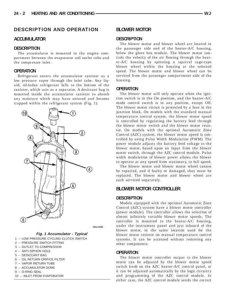
DESCRIPTIONThe compressor clutch assembly consists of a sta-
tionary electromagnetic coil, a hub bearing and pul-ley assembly, and a clutch plate (Fig. 2). Theelectromagnetic coil unit and the hub bearing andpulley assembly are each retained on the nose of thecompressor front housing with snap rings. The clutch
pw
O
mtcccppt
sAcpoecom
C
D
Snvt
24 - 4 HEATING AND AIR CONDITIONING WJ
DESCRIPTION AND OPERATION (Continued)
late is keyed to the compressor shaft and securedith a screw.
PERATIONThe compressor clutch components provide theeans to engage and disengage the compressor from
he engine serpentine accessory drive belt. When thelutch coil is energized, it magnetically draws thelutch into contact with the pulley and drives theompressor shaft. When the coil is not energized, theulley freewheels on the clutch hub bearing, which isart of the pulley. The compressor clutch and coil arehe only serviced parts on the compressor.
The compressor clutch engagement is controlled byeveral components: the A/C switch on the heater-/C control panel, the Automatic Zone Control (AZC)ontrol module (if the vehicle is so equipped), the lowressure cycling clutch switch, the high pressure cut-ff switch, the compressor clutch relay, and the Pow-rtrain Control Module (PCM). The PCM may delayompressor clutch engagement for up to thirty sec-nds. Refer to Group 14 - Fuel System for more infor-ation on the PCM controls.
OMPRESSOR CLUTCH RELAY
ESCRIPTIONThe compressor clutch relay is a International
tandards Organization (ISO) micro-relay. The termi-al designations and functions are the same as a con-entional ISO relay. However, the micro-relayerminal orientation (footprint) is different, the cur-
Fig. 2 Compressor Clutch - Typical1 – CLUTCH PLATE2 – SHAFT KEY3 – PULLEY4 – COIL5 – CLUTCH SHIMS6 – SNAP RING7 – SNAP RING
rent capacity is lower, and the relay case dimensionsare smaller than those of the conventional ISO relay.
OPERATIONThe compressor clutch relay is a electromechanical
device that switches battery current to the compres-sor clutch coil when the Powertrain Control Module(PCM) grounds the coil side of the relay. The PCMresponds to inputs from the A/C compressor switchon the heater-A/C control panel, the Automatic ZoneControl (AZC) control module (if the vehicle is soequipped), the low pressure cycling clutch switch,and the high pressure cut-off switch. See CompressorClutch Relay in the Diagnosis and Testing section ofthis group for more information.
The compressor clutch relay is located in the PowerDistribution Center (PDC) in the engine compart-ment. Refer to the PDC label for relay identificationand location.
The compressor clutch relay cannot be repairedand, if faulty or damaged, it must be replaced.
CONDENSER
DESCRIPTIONThe condenser is located in the air flow in front of
the engine cooling radiator. The condenser is a heatexchanger that allows the high-pressure refrigerantgas being discharged by the compressor to give up itsheat to the air passing over the condenser fins.
OPERATIONWhen the refrigerant gas gives up its heat, it con-
denses. When the refrigerant leaves the condenser, ithas become a high-pressure liquid refrigerant. Thevolume of air flowing over the condenser fins is crit-ical to the proper cooling performance of the air con-ditioning system. Therefore, it is important thatthere are no objects placed in front of the radiatorgrille openings in the front of the vehicle or foreignmaterial on the condenser fins that might obstructproper air flow. Also, any factory-installed air seals orshrouds must be properly reinstalled following radia-tor or condenser service.
The condenser cannot be repaired and, if faulty ordamaged, it must be replaced.
EVAPORATOR COIL
DESCRIPTIONThe evaporator coil is located in the heater-A/C
housing, under the instrument panel. The evaporatorcoil is positioned in the heater-A/C housing so thatall air that enters the housing must pass over thefins of the evaporator before it is distributed throughthe system ducts and outlets. However, air passing
owr
O
ouhhaib
f
F
D
btec
O
mhm(dttb
lpe
WJ HEATING AND AIR CONDITIONING 24 - 5
DESCRIPTION AND OPERATION (Continued)
ver the evaporator coil fins will only be conditionedhen the compressor is engaged and circulating
efrigerant through the evaporator coil tubes.
PERATIONRefrigerant enters the evaporator from the variable
rifice tube as a low-temperature, low-pressure liq-id. As air flows over the fins of the evaporator, theumidity in the air condenses on the fins, and theeat from the air is absorbed by the refrigerant. Heatbsorption causes the refrigerant to boil and vapor-ze. The refrigerant becomes a low-pressure gasefore it leaves the evaporator.The evaporator coil cannot be repaired and, if
aulty or damaged, it must be replaced.
IXED ORIFICE TUBE
ESCRIPTIONThe fixed orifice tube is installed in the liquid line
etween the outlet of the condenser and the inlet ofhe evaporator. The fixed orifice tube is located in thend of the liquid line or liquid line jumper that islosest to the condenser outlet tube.
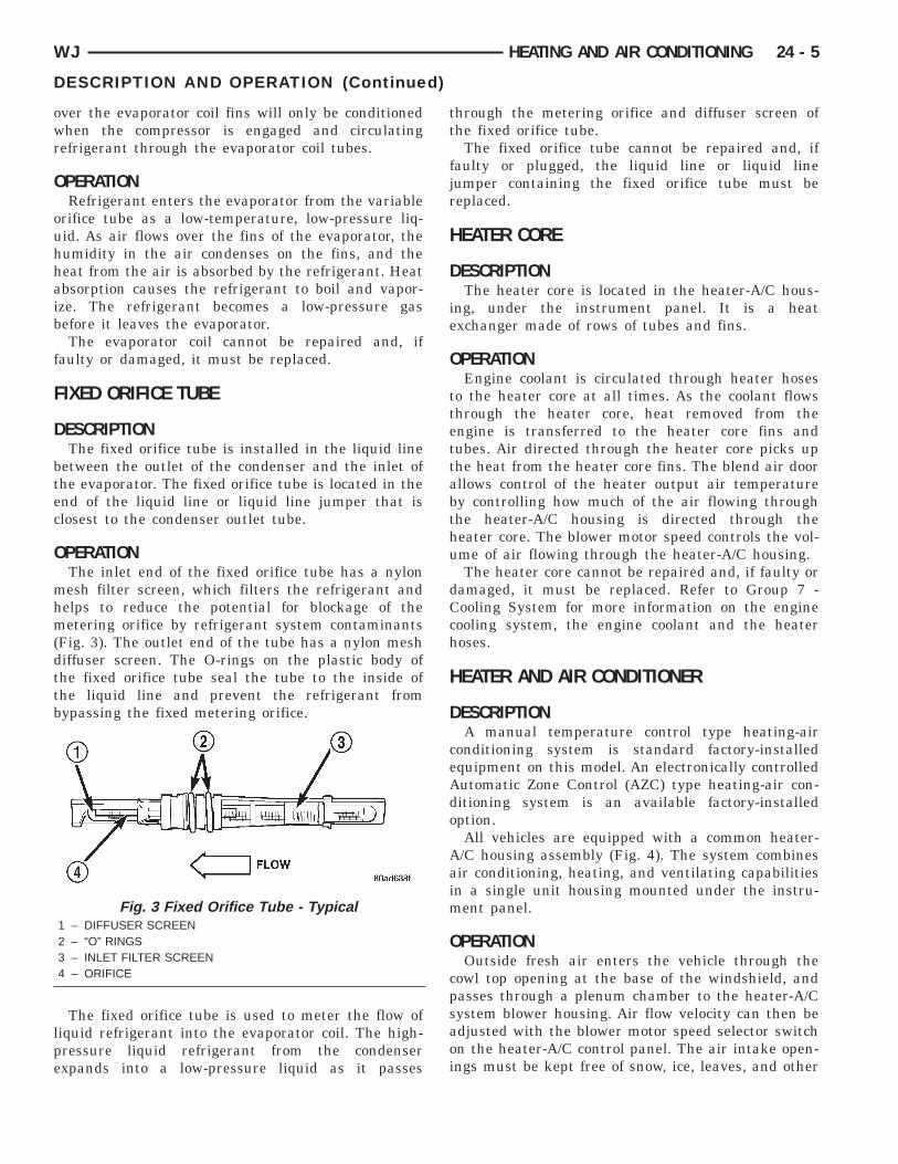
PERATIONThe inlet end of the fixed orifice tube has a nylonesh filter screen, which filters the refrigerant andelps to reduce the potential for blockage of theetering orifice by refrigerant system contaminants
Fig. 3). The outlet end of the tube has a nylon meshiffuser screen. The O-rings on the plastic body ofhe fixed orifice tube seal the tube to the inside ofhe liquid line and prevent the refrigerant fromypassing the fixed metering orifice.
The fixed orifice tube is used to meter the flow ofiquid refrigerant into the evaporator coil. The high-ressure liquid refrigerant from the condenserxpands into a low-pressure liquid as it passes
Fig. 3 Fixed Orifice Tube - Typical1 – DIFFUSER SCREEN2 – “O” RINGS3 – INLET FILTER SCREEN4 – ORIFICE
through the metering orifice and diffuser screen ofthe fixed orifice tube.
The fixed orifice tube cannot be repaired and, iffaulty or plugged, the liquid line or liquid linejumper containing the fixed orifice tube must bereplaced.
HEATER CORE
DESCRIPTIONThe heater core is located in the heater-A/C hous-
ing, under the instrument panel. It is a heatexchanger made of rows of tubes and fins.
OPERATIONEngine coolant is circulated through heater hoses
to the heater core at all times. As the coolant flowsthrough the heater core, heat removed from theengine is transferred to the heater core fins andtubes. Air directed through the heater core picks upthe heat from the heater core fins. The blend air doorallows control of the heater output air temperatureby controlling how much of the air flowing throughthe heater-A/C housing is directed through theheater core. The blower motor speed controls the vol-ume of air flowing through the heater-A/C housing.
The heater core cannot be repaired and, if faulty ordamaged, it must be replaced. Refer to Group 7 -Cooling System for more information on the enginecooling system, the engine coolant and the heaterhoses.
HEATER AND AIR CONDITIONER
DESCRIPTIONA manual temperature control type heating-air
conditioning system is standard factory-installedequipment on this model. An electronically controlledAutomatic Zone Control (AZC) type heating-air con-ditioning system is an available factory-installedoption.
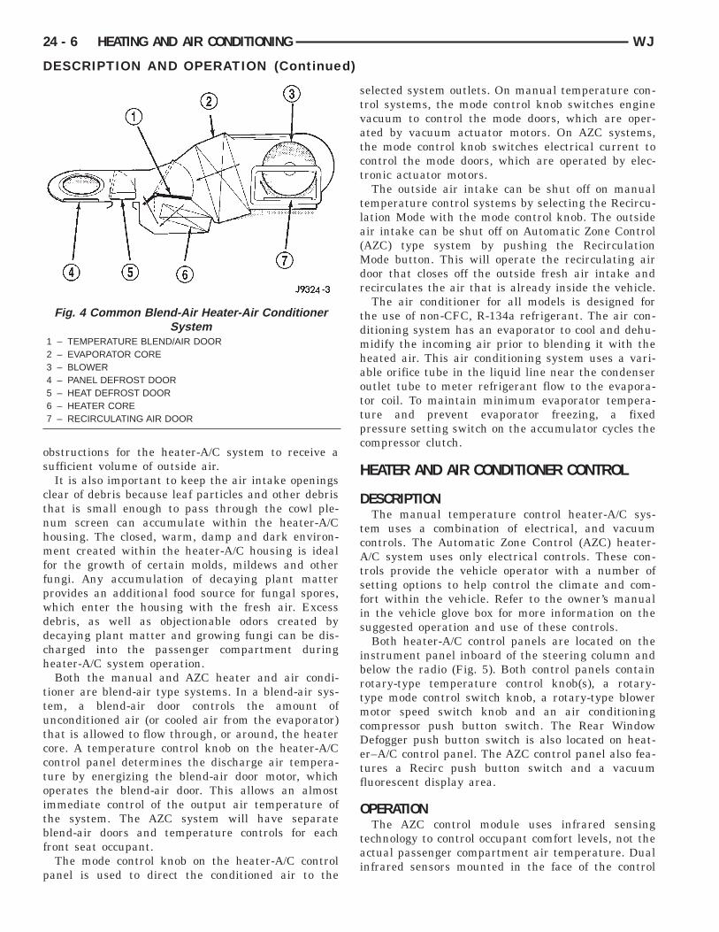
All vehicles are equipped with a common heater-A/C housing assembly (Fig. 4). The system combinesair conditioning, heating, and ventilating capabilitiesin a single unit housing mounted under the instru-ment panel.
OPERATIONOutside fresh air enters the vehicle through the
cowl top opening at the base of the windshield, andpasses through a plenum chamber to the heater-A/Csystem blower housing. Air flow velocity can then beadjusted with the blower motor speed selector switchon the heater-A/C control panel. The air intake open-ings must be kept free of snow, ice, leaves, and other
os
ctnhmffpwddch
ttutcctoitbf
p
24 - 6 HEATING AND AIR CONDITIONING WJ
DESCRIPTION AND OPERATION (Continued)
bstructions for the heater-A/C system to receive aufficient volume of outside air.It is also important to keep the air intake openings
lear of debris because leaf particles and other debrishat is small enough to pass through the cowl ple-um screen can accumulate within the heater-A/Cousing. The closed, warm, damp and dark environ-ent created within the heater-A/C housing is ideal
or the growth of certain molds, mildews and otherungi. Any accumulation of decaying plant matterrovides an additional food source for fungal spores,hich enter the housing with the fresh air. Excessebris, as well as objectionable odors created byecaying plant matter and growing fungi can be dis-harged into the passenger compartment duringeater-A/C system operation.Both the manual and AZC heater and air condi-
ioner are blend-air type systems. In a blend-air sys-em, a blend-air door controls the amount ofnconditioned air (or cooled air from the evaporator)hat is allowed to flow through, or around, the heaterore. A temperature control knob on the heater-A/Control panel determines the discharge air tempera-ure by energizing the blend-air door motor, whichperates the blend-air door. This allows an almostmmediate control of the output air temperature ofhe system. The AZC system will have separatelend-air doors and temperature controls for eachront seat occupant.
The mode control knob on the heater-A/C controlanel is used to direct the conditioned air to the
Fig. 4 Common Blend-Air Heater-Air ConditionerSystem
1 – TEMPERATURE BLEND/AIR DOOR2 – EVAPORATOR CORE3 – BLOWER4 – PANEL DEFROST DOOR5 – HEAT DEFROST DOOR6 – HEATER CORE7 – RECIRCULATING AIR DOOR
selected system outlets. On manual temperature con-trol systems, the mode control knob switches enginevacuum to control the mode doors, which are oper-ated by vacuum actuator motors. On AZC systems,the mode control knob switches electrical current tocontrol the mode doors, which are operated by elec-tronic actuator motors.
The outside air intake can be shut off on manualtemperature control systems by selecting the Recircu-lation Mode with the mode control knob. The outsideair intake can be shut off on Automatic Zone Control(AZC) type system by pushing the RecirculationMode button. This will operate the recirculating airdoor that closes off the outside fresh air intake andrecirculates the air that is already inside the vehicle.
The air conditioner for all models is designed forthe use of non-CFC, R-134a refrigerant. The air con-ditioning system has an evaporator to cool and dehu-midify the incoming air prior to blending it with theheated air. This air conditioning system uses a vari-able orifice tube in the liquid line near the condenseroutlet tube to meter refrigerant flow to the evapora-tor coil. To maintain minimum evaporator tempera-ture and prevent evaporator freezing, a fixedpressure setting switch on the accumulator cycles thecompressor clutch.
HEATER AND AIR CONDITIONER CONTROL
DESCRIPTIONThe manual temperature control heater-A/C sys-
tem uses a combination of electrical, and vacuumcontrols. The Automatic Zone Control (AZC) heater-A/C system uses only electrical controls. These con-trols provide the vehicle operator with a number ofsetting options to help control the climate and com-fort within the vehicle. Refer to the owner’s manualin the vehicle glove box for more information on thesuggested operation and use of these controls.
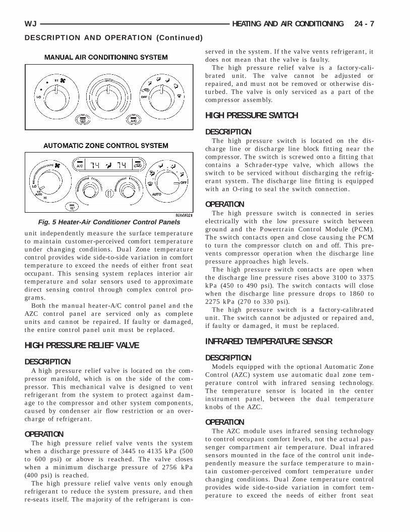
Both heater-A/C control panels are located on theinstrument panel inboard of the steering column andbelow the radio (Fig. 5). Both control panels containrotary-type temperature control knob(s), a rotary-type mode control switch knob, a rotary-type blowermotor speed switch knob and an air conditioningcompressor push button switch. The Rear WindowDefogger push button switch is also located on heat-er–A/C control panel. The AZC control panel also fea-tures a Recirc push button switch and a vacuumfluorescent display area.
OPERATIONThe AZC control module uses infrared sensing
technology to control occupant comfort levels, not theactual passenger compartment air temperature. Dualinfrared sensors mounted in the face of the control
utuctotdg
Aut
H
D
ppracc
O
wtw(
rr
WJ HEATING AND AIR CONDITIONING 24 - 7
DESCRIPTION AND OPERATION (Continued)
nit independently measure the surface temperatureo maintain customer-perceived comfort temperaturender changing conditions. Dual Zone temperatureontrol provides wide side-to-side variation in comfortemperature to exceed the needs of either front seatccupant. This sensing system replaces interior airemperature and solar sensors used to approximateirect sensing control through complex control pro-rams.Both the manual heater-A/C control panel and theZC control panel are serviced only as completenits and cannot be repaired. If faulty or damaged,he entire control panel unit must be replaced.
IGH PRESSURE RELIEF VALVE
ESCRIPTIONA high pressure relief valve is located on the com-
ressor manifold, which is on the side of the com-ressor. This mechanical valve is designed to ventefrigerant from the system to protect against dam-ge to the compressor and other system components,aused by condenser air flow restriction or an over-harge of refrigerant.
PERATIONThe high pressure relief valve vents the systemhen a discharge pressure of 3445 to 4135 kPa (500
o 600 psi) or above is reached. The valve closeshen a minimum discharge pressure of 2756 kPa
400 psi) is reached.The high pressure relief valve vents only enough
efrigerant to reduce the system pressure, and thene-seats itself. The majority of the refrigerant is con-
Fig. 5 Heater-Air Conditioner Control Panels
served in the system. If the valve vents refrigerant, itdoes not mean that the valve is faulty.
The high pressure relief valve is a factory-cali-brated unit. The valve cannot be adjusted orrepaired, and must not be removed or otherwise dis-turbed. The valve is only serviced as a part of thecompressor assembly.
HIGH PRESSURE SWITCH
DESCRIPTIONThe high pressure switch is located on the dis-
charge line or discharge line block fitting near thecompressor. The switch is screwed onto a fitting thatcontains a Schrader-type valve, which allows theswitch to be serviced without discharging the refrig-erant system. The discharge line fitting is equippedwith an O-ring to seal the switch connection.
OPERATIONThe high pressure switch is connected in series
electrically with the low pressure switch betweenground and the Powertrain Control Module (PCM).The switch contacts open and close causing the PCMto turn the compressor clutch on and off. This pre-vents compressor operation when the discharge linepressure approaches high levels.
The high pressure switch contacts are open whenthe discharge line pressure rises above 3100 to 3375kPa (450 to 490 psi). The switch contacts will closewhen the discharge line pressure drops to 1860 to2275 kPa (270 to 330 psi).
The high pressure switch is a factory-calibratedunit. The switch cannot be adjusted or repaired and,if faulty or damaged, it must be replaced.
INFRARED TEMPERATURE SENSOR
DESCRIPTIONModels equipped with the optional Automatic Zone
Control (AZC) system use automatic dual zone tem-perature control with infrared sensing technology.The temperature sensor is located in the centerinstrument panel, between the dual temperatureknobs of the AZC.
OPERATIONThe AZC module uses infrared sensing technology
to control occupant comfort levels, not the actual pas-senger compartment air temperature. Dual infraredsensors mounted in the face of the control unit inde-pendently measure the surface temperature to main-tain customer-perceived comfort temperature underchanging conditions. Dual Zone temperature controlprovides wide side-to-side variation in comfort tem-perature to exceed the needs of either front seat
otdg
am
NnioTa
L
D
alwctc
O
tgTtletot
tpsktcpi
uo
24 - 8 HEATING AND AIR CONDITIONING WJ
DESCRIPTION AND OPERATION (Continued)
ccupant. This sensing system replaces interior airemperature and solar sensors used to approximateirect sensing control through complex control pro-rams.The infrared temperature sensor cannot be
djusted or repaired and, if faulty or damaged, theodule must be replaced.
OTE: The infrared sensor window may be perma-ently damaged if any type of cosmetic vinyl dress-
ngs are allowed to contact the lens. Avoid sprayingr wiping this area with any cleaner or conditioner.his may result in impaired temperature sensingnd control.
OW PRESSURE SWITCH
ESCRIPTIONThe low pressure switch is located on the top of the
ccumulator. The switch is screwed onto an accumu-ator fitting that contains a Schrader-type valve,hich allows the switch to be serviced without dis-
harging the refrigerant system. The accumulator fit-ing is equipped with an O-ring to seal the switchonnection.
PERATIONThe low pressure switch is connected in series elec-
rically with the high pressure switch, betweenround and the Powertrain Control Module (PCM).he switch contacts open and close causing the PCMo turn the compressor clutch on and off. This regu-ates the refrigerant system pressure and controlsvaporator temperature. Controlling the evaporatoremperature prevents condensate water on the evap-rator fins from freezing and obstructing air condi-ioning system air flow.
The low pressure switch contacts are open whenhe suction pressure is approximately 152 kPa (22si) or lower. The switch contacts will close when theuction pressure rises to approximately 234 to 262Pa (34 to 38 psi) or above. Lower ambient tempera-ures, below approximately -1° C (30° F), will alsoause the switch contacts to open. This is due to theressure/temperature relationship of the refrigerantn the system.
The low pressure switch is a factory-calibratednit. It cannot be adjusted or repaired and, if faultyr damaged, it must be replaced.
REFRIGERANT
DESCRIPTIONThe refrigerant used in this air conditioning sys-
tem is a HydroFluoroCarbon (HFC), type R-134a.Unlike R-12, which is a ChloroFluoroCarbon (CFC),R-134a refrigerant does not contain ozone-depletingchlorine. R-134a refrigerant is a non-toxic, non-flam-mable, clear, and colorless liquefied gas.
Even though R-134a does not contain chlorine, itmust be reclaimed and recycled just like CFC-typerefrigerants. This is because R-134a is a greenhousegas and can contribute to global warming.
OPERATIONR-134a refrigerant is not compatible with R-12
refrigerant in an air conditioning system. Even asmall amount of R-12 added to an R-134a refrigerantsystem will cause compressor failure, refrigerant oilsludge or poor air conditioning system performance.In addition, the PolyAlkylene Glycol (PAG) syntheticrefrigerant oils used in an R-134a refrigerant systemare not compatible with the mineral-based refriger-ant oils used in an R-12 refrigerant system.
R-134a refrigerant system service ports, servicetool couplers and refrigerant dispensing bottles haveall been designed with unique fittings to ensure thatan R-134a system is not accidentally contaminatedwith the wrong refrigerant (R-12). There are alsolabels posted in the engine compartment of the vehi-cle and on the compressor identifying to service tech-nicians that the air conditioning system is equippedwith R-134a.
REFRIGERANT LINES
DESCRIPTIONThe refrigerant lines and hoses are used to carry
the refrigerant between the various air conditioningsystem components. A barrier hose design with anylon tube, which is sandwiched between rubber lay-ers, is used for the R-134a air conditioning system onthis vehicle. This nylon tube helps to further containthe R-134a refrigerant, which has a smaller molecu-lar structure than R-12 refrigerant. The ends of therefrigerant hoses are made from lightweight alumi-num or steel, and commonly use braze-less fittings.
itffaIbi
O
titpiap
obkmt
a
R
D
twon
ccNt
O
ecr
mioucn
WJ HEATING AND AIR CONDITIONING 24 - 9
DESCRIPTION AND OPERATION (Continued)
Any kinks or sharp bends in the refrigerant plumb-ng will reduce the capacity of the entire air condi-ioning system. Kinks and sharp bends reduce thelow of refrigerant in the system. A good rule for thelexible hose refrigerant lines is to keep the radius ofll bends at least ten times the diameter of the hose.n addition, the flexible hose refrigerant lines shoulde routed so they are at least 80 millimeters (3nches) from the exhaust manifold.
PERATIONHigh pressures are produced in the refrigerant sys-
em when the air conditioning compressor is operat-ng. Extreme care must be exercised to make surehat each of the refrigerant system connections isressure-tight and leak free. It is a good practice tonspect all flexible hose refrigerant lines at least once
year to make sure they are in good condition androperly routed.The refrigerant lines and hoses are coupled with
ther components of the HVAC system with peanut-lock style fittings. A stat-O seal type flat steel gas-et with a captured compressible O-ring, is used toate plumbing lines with A/C components to ensure
he integrity of the refrigerant system.The refrigerant lines and hoses cannot be repaired
nd, if faulty or damaged, they must be replaced.
EFRIGERANT OIL
ESCRIPTIONThe refrigerant oil used in R-134a refrigerant sys-
ems is a synthetic-based, PolyAlkylene Glycol (PAG),ax-free lubricant. Mineral-based R-12 refrigerantils are not compatible with PAG oils, and shouldever be introduced to an R-134a refrigerant system.There are different PAG oils available, and each
ontains a different additive package. The 10PA17ompressor used in this vehicle is designed to use anD8 PAG refrigerant oil. Use only refrigerant oil of
his same type to service the refrigerant system.
PERATIONwith the same amount of the recommended refrig-
rant oil as was removed. Too little refrigerant oilan cause compressor damage, and too much caneduce air conditioning system performance.PAG refrigerant oil is much more hygroscopic thanineral oil, and will absorb any moisture it comes
nto contact with, even moisture in the air. The PAGil container should always be kept tightly cappedntil it is ready to be used. After use, recap the oilontainer immediately to prevent moisture contami-ation.
After performing any refrigerant recovery or recy-cling operation, always replenish the refrigerant sys-tem
REFRIGERANT SYSTEM SERVICE PORTS
DESCRIPTIONThe two refrigerant system service ports are used
to charge, recover/recycle, evacuate, and test the airconditioning refrigerant system. Unique service portcoupler sizes are used on the R-134a system, toensure that the refrigerant system is not accidentallycontaminated by the use of the wrong refrigerant(R-12), or refrigerant system service equipment.
OPERATIONThe high pressure service port is located on the
discharge line off the side of the compressor. The lowpressure service port is located on the suction linenear the evaporator at the rear of the engine com-partment.
Each of the service ports has a threaded plasticprotective cap installed over it from the factory. Afterservicing the refrigerant system, always reinstallboth of the service port caps.
VACUUM CHECK VALVE
DESCRIPTIONTwo vacuum check valves (non AZC only) are
installed on the vacuum supply system. One is on theaccessory vacuum supply line in the engine compart-ment, near the vacuum tap on the engine intakemanifold. A second vacuum check valve is located onthe bottom of the HVAC unit behind the passengerfront floor duct on the black vacuum line. The vac-uum check valves are designed to allow vacuum toflow in only one direction through the accessory vac-uum supply circuits.
OPERATIONThe use of a vacuum check valve helps to maintain
the system vacuum needed to retain the selectedheater-A/C mode settings. The check valve will pre-vent the engine from bleeding down system vacuumthrough the intake manifold during extended heavyengine load (low engine vacuum) operation.
The vacuum check valve cannot be repaired and, iffaulty or damaged, it must be replaced.
VACUUM RESERVOIR
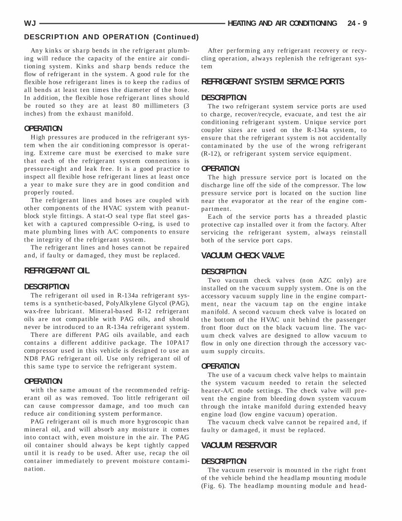
DESCRIPTIONThe vacuum reservoir is mounted in the right front
of the vehicle behind the headlamp mounting module(Fig. 6). The headlamp mounting module and head-
laGn
O
Tceaa
f
D
A
taitttraot
24 - 10 HEATING AND AIR CONDITIONING WJ
DESCRIPTION AND OPERATION (Continued)
amp assembly must be removed from the vehicle toccess the vacuum reservoir for service. Refer toroup 8L - Lamps for more information on compo-ent removal.
PERATIONEngine vacuum is stored in the vacuum reservoir.
he stored vacuum is used to operate the vacuum-ontrolled vehicle accessories during periods of lowngine vacuum such as when the vehicle is climbingsteep grade, or under other high engine load oper-
ting conditions.The vacuum reservoir cannot be repaired and, if
aulty or damaged, it must be replaced.
IAGNOSIS AND TESTING
/C PERFORMANCEThe air conditioning system is designed to provide
he passenger compartment with low temperaturend low specific humidity air. The evaporator, locatedn the heater-A/C housing on the dash panel belowhe instrument panel, is cooled to temperatures nearhe freezing point. As warm damp air passes throughhe cooled evaporator, the air transfers its heat to theefrigerant in the evaporator and the moisture in their condenses on the evaporator fins. During periodsf high heat and humidity, an air conditioning sys-em will be more effective in the Recirculation Mode.
Fig. 6 Vacuum Reservoir1 – FAN RELAY2 – CRUISE SERVO3 – VACUUM RESERVOIR
With the system in the Recirculation Mode, only airfrom the passenger compartment passes through theevaporator. As the passenger compartment air dehu-midifies, the air conditioning system performancelevels improve.
Humidity has an important bearing on the temper-ature of the air delivered to the interior of the vehi-cle. It is important to understand the effect thathumidity has on the performance of the air condition-ing system. When humidity is high, the evaporatorhas to perform a double duty. It must lower the airtemperature, and it must lower the temperature ofthe moisture in the air that condenses on the evapo-rator fins. Condensing the moisture in the air trans-fers heat energy into the evaporator fins and tubing.This reduces the amount of heat the evaporator canabsorb from the air. High humidity greatly reducesthe ability of the evaporator to lower the temperatureof the air.
However, evaporator capacity used to reduce theamount of moisture in the air is not wasted. Wring-ing some of the moisture out of the air entering thevehicle adds to the comfort of the passengers.Although, an owner may expect too much from theirair conditioning system on humid days. A perfor-mance test is the best way to determine whether thesystem is performing up to standard. This test alsoprovides valuable clues as to the possible cause oftrouble with the air conditioning system.
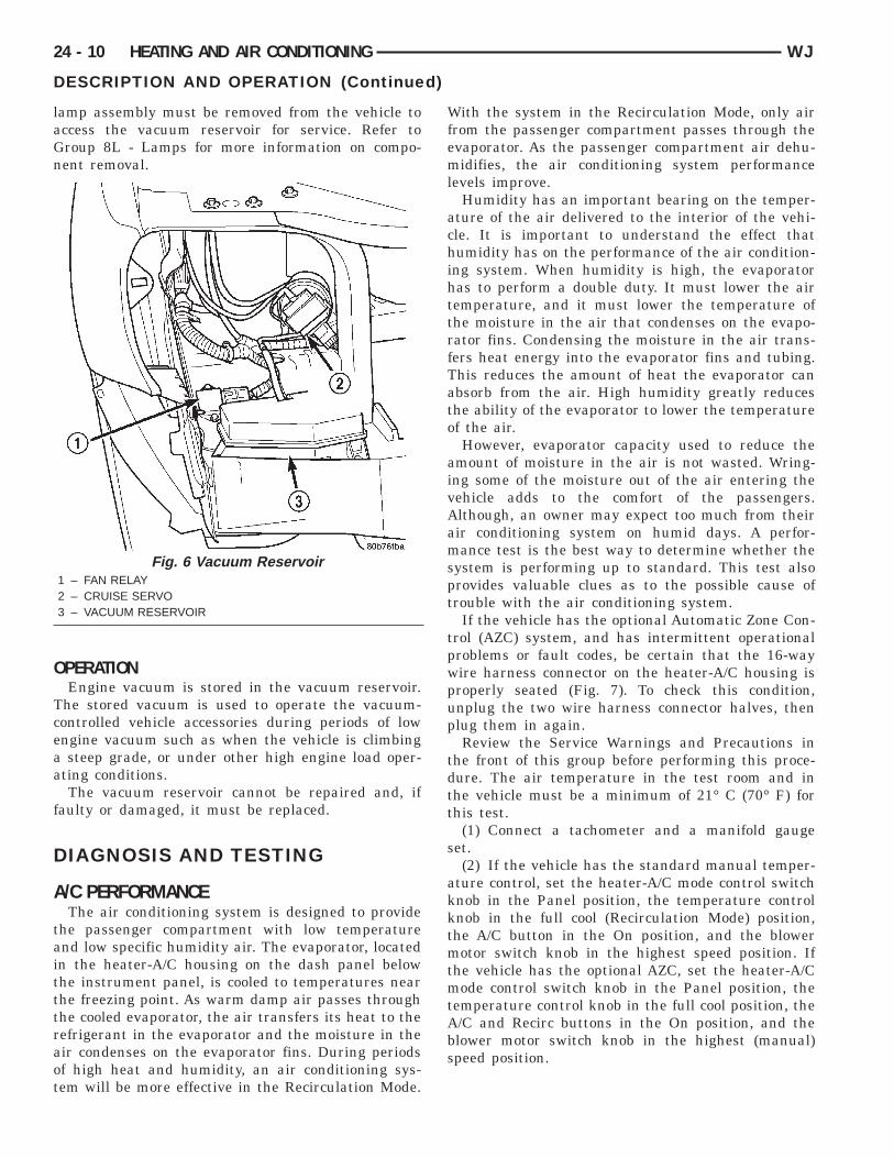
If the vehicle has the optional Automatic Zone Con-trol (AZC) system, and has intermittent operationalproblems or fault codes, be certain that the 16-waywire harness connector on the heater-A/C housing isproperly seated (Fig. 7). To check this condition,unplug the two wire harness connector halves, thenplug them in again.
Review the Service Warnings and Precautions inthe front of this group before performing this proce-dure. The air temperature in the test room and inthe vehicle must be a minimum of 21° C (70° F) forthis test.
(1) Connect a tachometer and a manifold gaugeset.
(2) If the vehicle has the standard manual temper-ature control, set the heater-A/C mode control switchknob in the Panel position, the temperature controlknob in the full cool (Recirculation Mode) position,the A/C button in the On position, and the blowermotor switch knob in the highest speed position. Ifthe vehicle has the optional AZC, set the heater-A/Cmode control switch knob in the Panel position, thetemperature control knob in the full cool position, theA/C and Recirc buttons in the On position, and theblower motor switch knob in the highest (manual)speed position.
w
T
Au
uchatc
WJ HEATING AND AIR CONDITIONING 24 - 11
DIAGNOSIS AND TESTING (Continued)
(3) Start the engine and hold the idle at 1,300 rpmith the compressor clutch engaged.(4) The engine should be at operating temperature.
he doors and windows must be open.(5) Insert a thermometer in the driver side center/C (panel) outlet. Operate the engine for five min-tes.(6) The compressor clutch may cycle, depending
pon the ambient temperature and humidity. If thelutch cycles, unplug the low pressure switch wirearness connector from the switch located on theccumulator (Fig. 8). Place a jumper wire across theerminals of the low pressure switch wire harness
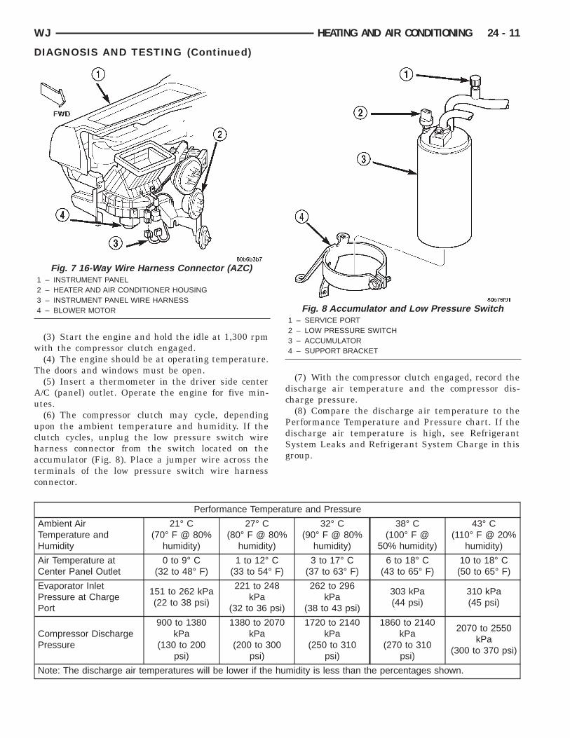
Fig. 7 16-Way Wire Harness Connector (AZC)1 – INSTRUMENT PANEL2 – HEATER AND AIR CONDITIONER HOUSING3 – INSTRUMENT PANEL WIRE HARNESS4 – BLOWER MOTOR
onnector.
(7) With the compressor clutch engaged, record thedischarge air temperature and the compressor dis-charge pressure.
(8) Compare the discharge air temperature to thePerformance Temperature and Pressure chart. If thedischarge air temperature is high, see RefrigerantSystem Leaks and Refrigerant System Charge in thisgroup.
Fig. 8 Accumulator and Low Pressure Switch1 – SERVICE PORT2 – LOW PRESSURE SWITCH3 – ACCUMULATOR4 – SUPPORT BRACKET
Performance Temperature and Pressure
Ambient AirTemperature andHumidity
21° C(70° F @ 80%
humidity)
27° C(80° F @ 80%
humidity)
32° C(90° F @ 80%
humidity)
38° C(100° F @
50% humidity)
43° C(110° F @ 20%
humidity)
Air Temperature atCenter Panel Outlet
0 to 9° C(32 to 48° F)
1 to 12° C(33 to 54° F)
3 to 17° C(37 to 63° F)
6 to 18° C(43 to 65° F)
10 to 18° C(50 to 65° F)
Evaporator InletPressure at ChargePort
151 to 262 kPa(22 to 38 psi)
221 to 248kPa
(32 to 36 psi)
262 to 296kPa
(38 to 43 psi)
303 kPa(44 psi)
310 kPa(45 psi)
Compressor DischargePressure
900 to 1380kPa
(130 to 200psi)
1380 to 2070kPa
(200 to 300psi)
1720 to 2140kPa
(250 to 310psi)
1860 to 2140kPa
(270 to 310psi)
2070 to 2550kPa
(300 to 370 psi)
Note: The discharge air temperatures will be lower if the humidity is less than the percentages shown.
t
24 - 12 HEATING AND AIR CONDITIONING WJ
DIAGNOSIS AND TESTING (Continued)
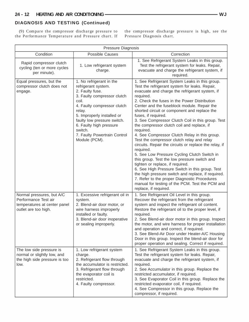
(9) Compare the compressor discharge pressure to
he Performance Temperature and Pressure chart. Ifthe compressor discharge pressure is high, see the
Pressure Diagnosis chart.Pressure Diagnosis
Condition Possible Causes Correction
Rapid compressor clutchcycling (ten or more cycles
per minute).
1. Low refrigerant systemcharge.
1. See Refrigerant System Leaks in this group.Test the refrigerant system for leaks. Repair,
evacuate and charge the refrigerant system, ifrequired.
Equal pressures, but thecompressor clutch does notengage.
1. No refrigerant in therefrigerant system.2. Faulty fuse.3. Faulty compressor clutchcoil.4. Faulty compressor clutchrelay.5. Improperly installed orfaulty low pressure switch.6. Faulty high pressureswitch.7. Faulty Powertrain ControlModule (PCM).
1. See Refrigerant System Leaks in this group.Test the refrigerant system for leaks. Repair,evacuate and charge the refrigerant system, ifrequired.2. Check the fuses in the Power DistributionCenter and the fuseblock module. Repair theshorted circuit or component and replace thefuses, if required.3. See Compressor Clutch Coil in this group. Testthe compressor clutch coil and replace, ifrequired.4. See Compressor Clutch Relay in this group.Test the compressor clutch relay and relaycircuits. Repair the circuits or replace the relay, ifrequired.5. See Low Pressure Cycling Clutch Switch inthis group. Test the low pressure switch andtighten or replace, if required.6. See High Pressure Switch in this group. Testthe high pressure switch and replace, if required.7. Refer to the proper Diagnostic Proceduresmanual for testing of the PCM. Test the PCM andreplace, if required.
Normal pressures, but A/CPerformance Test airtemperatures at center paneloutlet are too high.
1. Excessive refrigerant oil insystem.2. Blend-air door motor, orwire harness improperlyinstalled or faulty.3. Blend-air door inoperativeor sealing improperly.
1. See Refrigerant Oil Level in this group.Recover the refrigerant from the refrigerantsystem and inspect the refrigerant oil content.Restore the refrigerant oil to the proper level, ifrequired.2. See Blend-air door motor in this group. Inspectthe motor, and wire harness for proper installationand operation and correct, if required.3. See Blend-Air Door under Heater-A/C HousingDoor in this group. Inspect the blend-air door forproper operation and sealing. Correct if required.
The low side pressure isnormal or slightly low, andthe high side pressure is toolow.
1. Low refrigerant systemcharge.2. Refrigerant flow throughthe accumulator is restricted.3. Refrigerant flow throughthe evaporator coil isrestricted.4. Faulty compressor.
1. See Refrigerant System Leaks in this group.Test the refrigerant system for leaks. Repair,evacuate and charge the refrigerant system, ifrequired.2. See Accumulator in this group. Replace therestricted accumulator, if required.3. See Evaporator Coil in this group. Replace therestricted evaporator coil, if required.4. See Compressor in this group. Replace thecompressor, if required.

A
hmohcuifta
WJ HEATING AND AIR CONDITIONING 24 - 13
DIAGNOSIS AND TESTING (Continued)
Pressure Diagnosis
Condition Possible Causes Correction
The low side pressure isnormal or slightly high, andthe high side pressure is toohigh.
1. Condenser air flowrestricted.2. Inoperative cooling fan.3. Refrigerant systemovercharged.4. Air in the refrigerantsystem.5. Engine overheating.
1. Check the condenser for damaged fins, foreignobjects obstructing air flow through the condenserfins, and missing or improperly installed air seals.Refer to Group 7 - Cooling System for moreinformation on air seals. Clean, repair, or replacecomponents as required.2. Refer to Group 7 - Cooling System for moreinformation. Test the cooling fan and replace, ifrequired.3. See Refrigerant System Charge in this group.Recover the refrigerant from the refrigerantsystem. Charge the refrigerant system to theproper level, if required.4. See Refrigerant System Leaks in this group.Test the refrigerant system for leaks. Repair,evacuate and charge the refrigerant system, ifrequired.5. Refer to Group 7 - Cooling System for moreinformation. Test the cooling system and repair, ifrequired.
The low side pressure is toohigh, and the high sidepressure is too low.
1. Accessory drive beltslipping.2. Variable orifice tube notinstalled.3. Faulty compressor.
1. Refer to Group 7 - Cooling System for moreinformation. Inspect the accessory drive beltcondition and tension. Tighten or replace theaccessory drive belt, if required.2. See Variable Orifice Tube in this group. Installthe missing orifice tube and line if required.3. See Compressor in this group. Replace thecompressor, if required.
The low side pressure is toolow, and the high sidepressure is too high.
1. Restricted refrigerant flowthrough the refrigerant lines.2. Restricted refrigerant flowthrough the variable orificetube.3. Restricted refrigerant flowthrough the condenser.
1. See Liquid Line and Suction and DischargeLine in this group. Inspect the refrigerant lines forkinks, tight bends or improper routing. Correct therouting or replace the refrigerant line, if required.2. See Variable Orifice Tube in this group.Replace the restricted fixed orifice tube, ifrequired.3. See Condenser in this group. Replace therestricted condenser, if required.
UTOMATIC ZONE CONTROL SYSTEMThe Automatic Zone Control (AZC) control module
as a system self-diagnostic mode which continuouslyonitors various parameters during normal system
peration. If a system fault is detected, a current andistorical fault is recorded. When the current fault isleared, the historical fault remains until reset (man-ally or automatically). Both the current and histor-
cal fault codes can be accessed through either theront panel, or over the Programmable Communica-ions Interface (PCI) bus using a DRBIIIt scan tool,nd the proper Diagnostic Procedures manual.
The AZC control module is capable of three differ-ent types of self-diagnostic tests, as follows:
• Fault Code Tests• Input Circuit Tests• Output Circuit/Actuator TestsThe information that follows describes:• How to read the self-diagnostic display• How to enter the AZC control module self-diag-
nostic test mode• How to select the self-diagnostic test types• How to perform the different tests
E
f
st
tapdavA
Amaede
24 - 14 HEATING AND AIR CONDITIONING WJ
DIAGNOSIS AND TESTING (Continued)
NTERING THE AZC SELF-DIAGNOSTIC MODETo enter the AZC self-diagnostic mode, perform the
ollowing:(1) Depress the A/C and Recirc buttons at the
ame time and hold. Rotate the left temperature con-rol knob clockwise (CW) one detent.
(2) If you continue to hold the A/C and Recirc but-ons depressed, the AZC control module will perform
Segment Test of the vacuum fluorescent (VF) dis-lay. In the Segment Test you should see all of theisplay segments illuminate as long as both buttonsre held. If a display segment fails to illuminate, theacuum fluorescent display is faulty and the heater-/C control must be replaced.(3) After viewing the Segment Test, release the/C and Recirc buttons and the display will clearomentarily. If a 0 is displayed, then no faultsre set in the system. Should there be any faults,ither “current9 or “historical”, all fault codes will beisplayed in ascending numerical sequence (note noffort is made to display fault codes in chronological
order). Each fault code is displayed for one secondbefore the next code is displayed. Once all fault codeshave been displayed, the system will then repeat thefault code numbers. This will continue until the leftside set temperature control is moved at least onedetent position in the CW direction or the ignition isturned “OFF”.
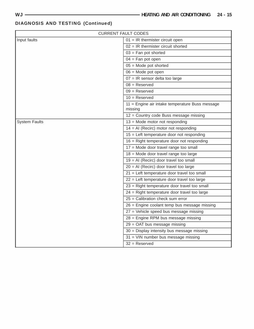
FAULT CODE TESTSFault codes are two-digit numbers that identify a
circuit that is malfunctioning. There are two differ-ent kinds of fault codes.
1. Current Fault Codes - Current means thefault is present right now. There are two types of cur-rent faults: input faults, and system faults.
2. Historical Fault Codes - Historical or storedmeans that the fault occurred previously, but is notpresent right now. A majority of historical fault codesare caused by intermittent wire harness or wire har-ness connector problems.
WJ HEATING AND AIR CONDITIONING 24 - 15
DIAGNOSIS AND TESTING (Continued)
CURRENT FAULT CODES
Input faults 01 = IR thermister circuit open
02 = IR thermister circuit shorted
03 = Fan pot shorted
04 = Fan pot open
05 = Mode pot shorted
06 = Mode pot open
07 = IR sensor delta too large
08 = Reserved
09 = Reserved
10 = Reserved
11 = Engine air intake temperature Buss messagemissing
12 = Country code Buss message missing
System Faults 13 = Mode motor not responding
14 = AI (Recirc) motor not responding
15 = Left temperature door not responding
16 = Right temperature door not responding
17 = Mode door travel range too small
18 = Mode door travel range too large
19 = AI (Recirc) door travel too small
20 = AI (Recirc) door travel too large
21 = Left temperature door travel too small
22 = Left temperature door travel too large
23 = Right temperature door travel too small
24 = Right temperature door travel too large
25 = Calibration check sum error
26 = Engine coolant temp bus message missing
27 = Vehicle speed bus message missing
28 = Engine RPM bus message missing
29 = OAT bus message missing
30 = Display intensity bus message missing
31 = VIN number bus message missing
32 = Reserved
24 - 16 HEATING AND AIR CONDITIONING WJ
DIAGNOSIS AND TESTING (Continued)
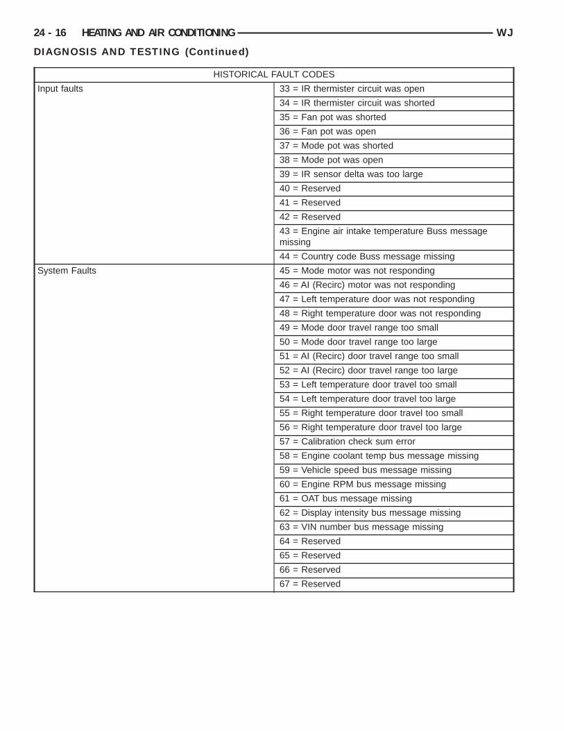
HISTORICAL FAULT CODES
Input faults 33 = IR thermister circuit was open
34 = IR thermister circuit was shorted
35 = Fan pot was shorted
36 = Fan pot was open
37 = Mode pot was shorted
38 = Mode pot was open
39 = IR sensor delta was too large
40 = Reserved
41 = Reserved
42 = Reserved
43 = Engine air intake temperature Buss messagemissing
44 = Country code Buss message missing
System Faults 45 = Mode motor was not responding
46 = AI (Recirc) motor was not responding
47 = Left temperature door was not responding
48 = Right temperature door was not responding
49 = Mode door travel range too small
50 = Mode door travel range too large
51 = AI (Recirc) door travel range too small
52 = AI (Recirc) door travel range too large
53 = Left temperature door travel too small
54 = Left temperature door travel too large
55 = Right temperature door travel too small
56 = Right temperature door travel too large
57 = Calibration check sum error
58 = Engine coolant temp bus message missing
59 = Vehicle speed bus message missing
60 = Engine RPM bus message missing
61 = OAT bus message missing
62 = Display intensity bus message missing
63 = VIN number bus message missing
64 = Reserved
65 = Reserved
66 = Reserved
67 = Reserved
NsAf
R
ald
ptseobptbntpaitd
C
Rfciodicacz
E
bt
rb9ftr
WJ HEATING AND AIR CONDITIONING 24 - 17
DIAGNOSIS AND TESTING (Continued)
OTE: A battery disconnect will erase all faultstored in Random Access Memory (RAM) of theZC control module. It is recommended that all
aults be recorded before they are erased.
ETRIEVING FAULT CODES(1) To begin the fault code tests, depress the A/C
nd Recirc buttons at the same time and rotate theeft temperature control knob clockwise (CW) oneetent, then release the push-button.(2) If there are no fault codes, the “00” dis-
lay value will remain in the VF window. Shouldhere be any codes, each will be displayed for oneecond in ascending numerical sequence (note: noffort is made to display faults in the order theyccurred). The left side set temperature display wille blanked and the right side set temperature dis-lay will indicate current and historical codes (8 his-orical max) presently active. Once all codes haveeen displayed, the system will repeat the fault codeumbers. This will continue until the left side setemperature control is moved at least one detentosition in either direction, by pressing both the A/Cnd Recirc buttons at the same time, or the ignitions turned off. Record all of the fault codes, then seehe Current and Historical Fault Code charts for theescriptions.
LEARING FAULT CODESCurrent faults cannot be electronically cleared.epair must be made to the system to eliminate the
ault causing code. Historical fault codes can beleared manually, or automatically. To clear a histor-cal fault manually, depress and hold either the A/Cr Recirc button for at least three seconds while theisplay is in the fault code mode of operation. Histor-cal fault codes are cleared automatically when theorresponding current fault code has been cleared,nd has remained cleared for a number of ignitionycles. The faults have been cleared when two hori-ontal bars appear in the Test Selector display.
XITING SELF-DIAGNOSTIC MODEThe self-diagnostic mode can be exited by pressing
oth the A/C and Recirc buttons at the same time, or
urning off the ignition.MONITOR CURRENT PARAMETERSWhile in the display fault code mode of operation,
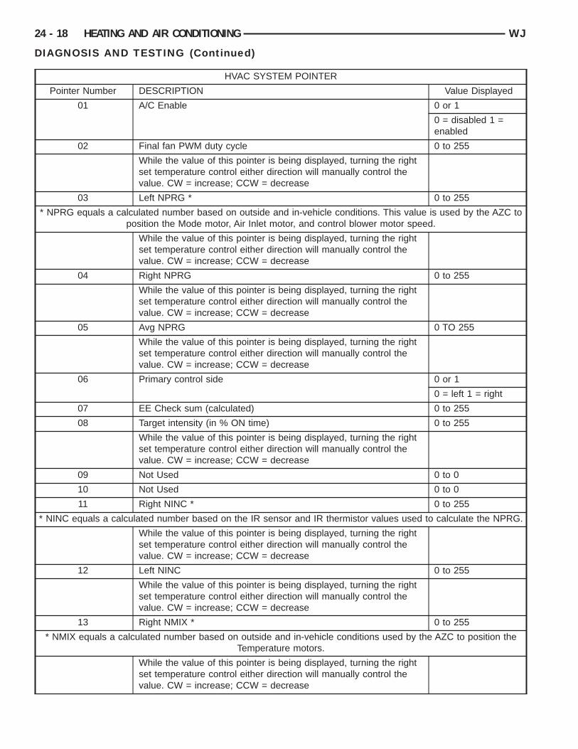
current system parameters can also be monitoredand/or forced. Rotating the left side set temperaturecontrol clockwise will increase the pointer numberwhile rotating the control counter clockwise willdecrease the pointer number. Rotating the right settemperature control will have no impact on pointervalue or the value of the parameter being monitored.Once the desired pointer number has been selected,pressing either the AC or Recirc buttons will displaythe current value of the selected parameter. Theight side set temperature display is only capa-le of displaying only values ranging from 0 to9, the left side set temperature display is usedor values greater than 99. If the value is lesshan 99, the left side set temperature displayemains blanked. While a parameter is being over-
ridden, the system will continue to function normallyexcept for the parameter which is being manuallycontrolled.
For values < 0, the “G” segment in the left side settemperature Most Significant Digit (MSD)(or left-most number in the pair) will be used to indicate anegative number. For values between -01 to -99 theLeast Significant Digit (LSD)(or right-most numberof the pair) in the left side set temperature willremain blank. System control of parameter being dis-played can be overridden by rotating the right settemperature control in either direction. Rotating theright temperature control in the CW direction, theselected parameter value is overridden and incre-mented beginning at the value which was being dis-played. Rotating the right temperature control in theCCW direction, the selected parameter value is over-ridden and decremented beginning at the valuewhich was being displayed. The rate at which incre-menting and decrement occurs is one unit value perset temperature detent position.
24 - 18 HEATING AND AIR CONDITIONING WJ
DIAGNOSIS AND TESTING (Continued)
HVAC SYSTEM POINTER
Pointer Number DESCRIPTION Value Displayed
01 A/C Enable 0 or 1
0 = disabled 1 =enabled
02 Final fan PWM duty cycle 0 to 255
While the value of this pointer is being displayed, turning the rightset temperature control either direction will manually control thevalue. CW = increase; CCW = decrease
03 Left NPRG * 0 to 255
* NPRG equals a calculated number based on outside and in-vehicle conditions. This value is used by the AZC toposition the Mode motor, Air Inlet motor, and control blower motor speed.
While the value of this pointer is being displayed, turning the rightset temperature control either direction will manually control thevalue. CW = increase; CCW = decrease
04 Right NPRG 0 to 255
While the value of this pointer is being displayed, turning the rightset temperature control either direction will manually control thevalue. CW = increase; CCW = decrease
05 Avg NPRG 0 TO 255
While the value of this pointer is being displayed, turning the rightset temperature control either direction will manually control thevalue. CW = increase; CCW = decrease
06 Primary control side 0 or 1
0 = left 1 = right
07 EE Check sum (calculated) 0 to 255
08 Target intensity (in % ON time) 0 to 255
While the value of this pointer is being displayed, turning the rightset temperature control either direction will manually control thevalue. CW = increase; CCW = decrease
09 Not Used 0 to 0
10 Not Used 0 to 0
11 Right NINC * 0 to 255
* NINC equals a calculated number based on the IR sensor and IR thermistor values used to calculate the NPRG.
While the value of this pointer is being displayed, turning the rightset temperature control either direction will manually control thevalue. CW = increase; CCW = decrease
12 Left NINC 0 to 255
While the value of this pointer is being displayed, turning the rightset temperature control either direction will manually control thevalue. CW = increase; CCW = decrease
13 Right NMIX * 0 to 255
* NMIX equals a calculated number based on outside and in-vehicle conditions used by the AZC to position theTemperature motors.
While the value of this pointer is being displayed, turning the rightset temperature control either direction will manually control thevalue. CW = increase; CCW = decrease
WJ HEATING AND AIR CONDITIONING 24 - 19
DIAGNOSIS AND TESTING (Continued)
HVAC SYSTEM POINTER
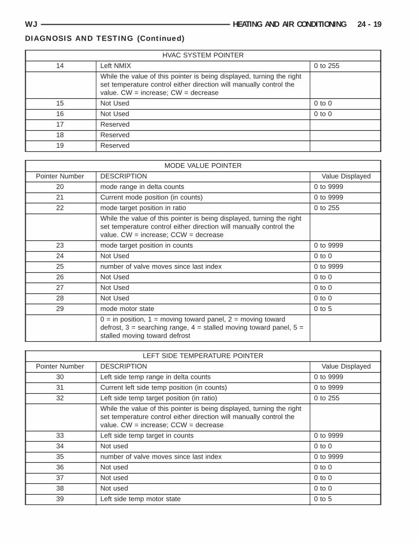
14 Left NMIX 0 to 255
While the value of this pointer is being displayed, turning the rightset temperature control either direction will manually control thevalue. CW = increase; CW = decrease
15 Not Used 0 to 0
16 Not Used 0 to 0
17 Reserved
18 Reserved
19 Reserved
MODE VALUE POINTER
Pointer Number DESCRIPTION Value Displayed
20 mode range in delta counts 0 to 9999
21 Current mode position (in counts) 0 to 9999
22 mode target position in ratio 0 to 255
While the value of this pointer is being displayed, turning the rightset temperature control either direction will manually control thevalue. CW = increase; CCW = decrease
23 mode target position in counts 0 to 9999
24 Not Used 0 to 0
25 number of valve moves since last index 0 to 9999
26 Not Used 0 to 0
27 Not Used 0 to 0
28 Not Used 0 to 0
29 mode motor state 0 to 5
0 = in position, 1 = moving toward panel, 2 = moving towarddefrost, 3 = searching range, 4 = stalled moving toward panel, 5 =stalled moving toward defrost
LEFT SIDE TEMPERATURE POINTER
Pointer Number DESCRIPTION Value Displayed
30 Left side temp range in delta counts 0 to 9999
31 Current left side temp position (in counts) 0 to 9999
32 Left side temp target position (in ratio) 0 to 255
While the value of this pointer is being displayed, turning the rightset temperature control either direction will manually control thevalue. CW = increase; CCW = decrease
33 Left side temp target in counts 0 to 9999
34 Not used 0 to 0
35 number of valve moves since last index 0 to 9999
36 Not used 0 to 0
37 Not used 0 to 0
38 Not used 0 to 0
39 Left side temp motor state 0 to 5
24 - 20 HEATING AND AIR CONDITIONING WJ
DIAGNOSIS AND TESTING (Continued)
LEFT SIDE TEMPERATURE POINTER
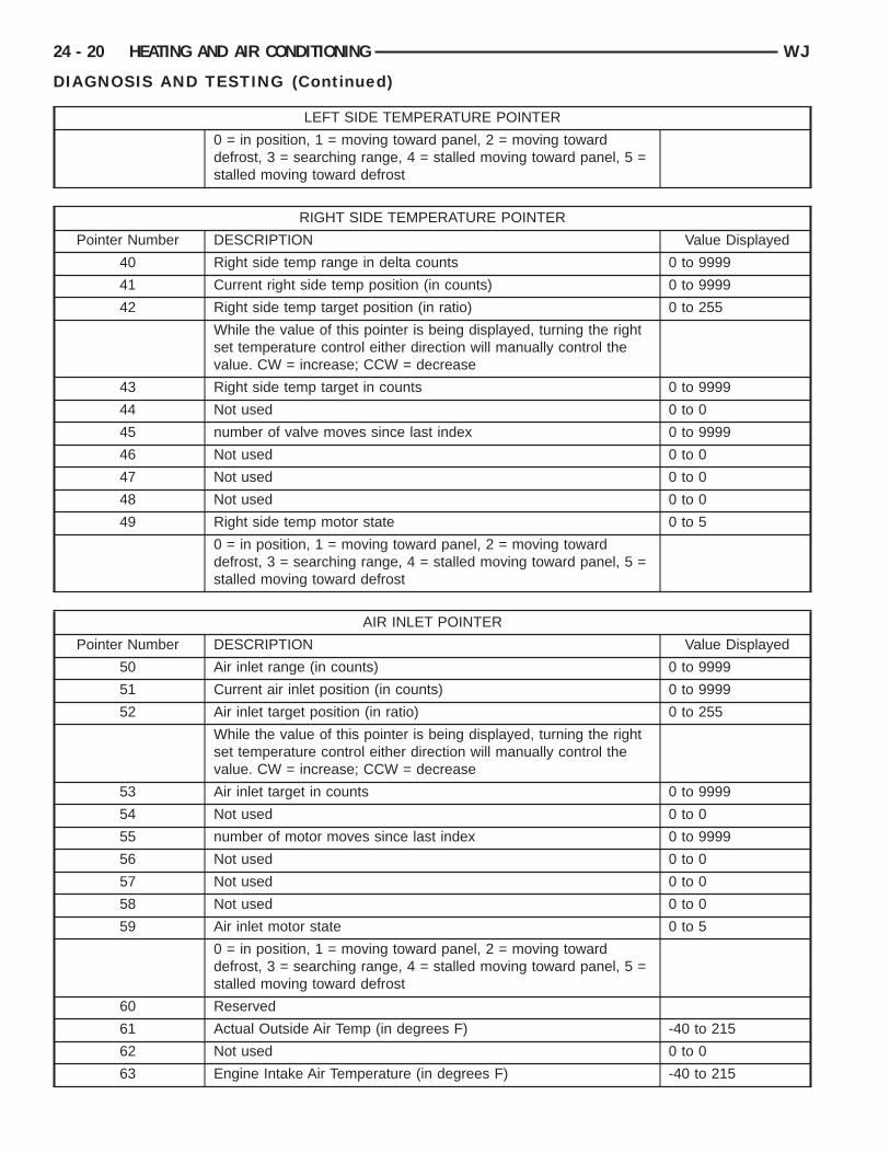
0 = in position, 1 = moving toward panel, 2 = moving towarddefrost, 3 = searching range, 4 = stalled moving toward panel, 5 =stalled moving toward defrost
RIGHT SIDE TEMPERATURE POINTER
Pointer Number DESCRIPTION Value Displayed
40 Right side temp range in delta counts 0 to 9999
41 Current right side temp position (in counts) 0 to 9999
42 Right side temp target position (in ratio) 0 to 255
While the value of this pointer is being displayed, turning the rightset temperature control either direction will manually control thevalue. CW = increase; CCW = decrease
43 Right side temp target in counts 0 to 9999
44 Not used 0 to 0
45 number of valve moves since last index 0 to 9999
46 Not used 0 to 0
47 Not used 0 to 0
48 Not used 0 to 0
49 Right side temp motor state 0 to 5
0 = in position, 1 = moving toward panel, 2 = moving towarddefrost, 3 = searching range, 4 = stalled moving toward panel, 5 =stalled moving toward defrost
AIR INLET POINTER
Pointer Number DESCRIPTION Value Displayed
50 Air inlet range (in counts) 0 to 9999
51 Current air inlet position (in counts) 0 to 9999
52 Air inlet target position (in ratio) 0 to 255
While the value of this pointer is being displayed, turning the rightset temperature control either direction will manually control thevalue. CW = increase; CCW = decrease
53 Air inlet target in counts 0 to 9999
54 Not used 0 to 0
55 number of motor moves since last index 0 to 9999
56 Not used 0 to 0
57 Not used 0 to 0
58 Not used 0 to 0
59 Air inlet motor state 0 to 5
0 = in position, 1 = moving toward panel, 2 = moving towarddefrost, 3 = searching range, 4 = stalled moving toward panel, 5 =stalled moving toward defrost
60 Reserved
61 Actual Outside Air Temp (in degrees F) -40 to 215
62 Not used 0 to 0
63 Engine Intake Air Temperature (in degrees F) -40 to 215
WJ HEATING AND AIR CONDITIONING 24 - 21
DIAGNOSIS AND TESTING (Continued)
AIR INLET POINTER
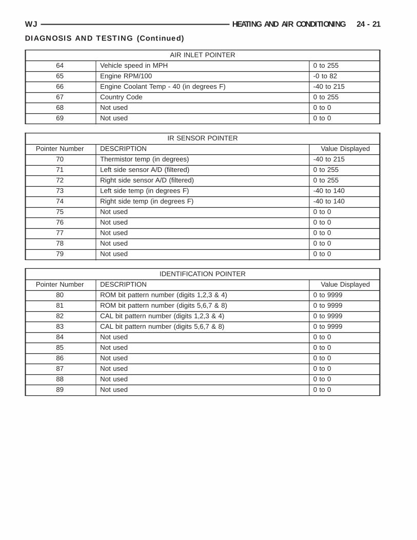
64 Vehicle speed in MPH 0 to 255
65 Engine RPM/100 -0 to 82
66 Engine Coolant Temp - 40 (in degrees F) -40 to 215
67 Country Code 0 to 255
68 Not used 0 to 0
69 Not used 0 to 0
IR SENSOR POINTER
Pointer Number DESCRIPTION Value Displayed
70 Thermistor temp (in degrees) -40 to 215
71 Left side sensor A/D (filtered) 0 to 255
72 Right side sensor A/D (filtered) 0 to 255
73 Left side temp (in degrees F) -40 to 140
74 Right side temp (in degrees F) -40 to 140
75 Not used 0 to 0
76 Not used 0 to 0
77 Not used 0 to 0
78 Not used 0 to 0
79 Not used 0 to 0
IDENTIFICATION POINTER
Pointer Number DESCRIPTION Value Displayed
80 ROM bit pattern number (digits 1,2,3 & 4) 0 to 9999
81 ROM bit pattern number (digits 5,6,7 & 8) 0 to 9999
82 CAL bit pattern number (digits 1,2,3 & 4) 0 to 9999
83 CAL bit pattern number (digits 5,6,7 & 8) 0 to 9999
84 Not used 0 to 0
85 Not used 0 to 0
86 Not used 0 to 0
87 Not used 0 to 0
88 Not used 0 to 0
89 Not used 0 to 0
O
pata
m
ataTiu
Rt
Rk
B
WBRSISCBI
8ib
n
e
c
i
e
(
24 - 22 HEATING AND AIR CONDITIONING WJ
DIAGNOSIS AND TESTING (Continued)
UTPUT CIRCUIT/ACTUATOR TESTSIn the Output Circuit/Actuator Test mode, the out-
ut circuits can be viewed, monitored, overridden,nd tested. If a failure occurs in an output circuit,est the circuit by overriding the system. Test thectuator through its full range of operation.(1) To begin the Output Circuit/Actuator Tests youust be in the Select Test mode.(2) With a “00” value displayed in the Test Selector
nd no stick man, turn the rotary temperature con-rol knob until the test number you are looking forppears in the Test Selector display. See the Circuitesting charts for a listing of the test numbers, testtems, test types, system tested, and displayed val-es.(3) To see the output value, depress the A/C orecirc button. The values displayed will represent
he output from the AZC control module.(4) To enter the actuator test, depress the A/C orecirc button. Then, rotate the right temperature setnob to the desired position.
LOWER MOTOR
ARNING: ON VEHICLES EQUIPPED WITH AIR-AGS, REFER TO GROUP 8M - PASSIVEESTRAINT SYSTEMS BEFORE ATTEMPTING ANYTEERING WHEEL, STEERING COLUMN, OR
NSTRUMENT PANEL COMPONENT DIAGNOSIS ORERVICE. FAILURE TO TAKE THE PROPER PRE-AUTIONS COULD RESULT IN ACCIDENTAL AIR-AG DEPLOYMENT AND POSSIBLE PERSONAL
NJURY.
For circuit descriptions and diagrams, refer toW-42 - Air Conditioning/Heater in Group 8W - Wir-ng Diagrams. Possible causes of an inoperativelower motor include:• Faulty fuse• Faulty blower motor circuit wiring or wire har-
ess connections• Faulty blower motor resistor (if the vehicle is so
quipped)• Faulty blower motor power module (if the vehi-
le is so equipped)• Faulty blower motor switch• Faulty heater-A/C mode control switch• Faulty blower motor.Possible causes of the blower motor not operating
n all speeds include:• Faulty fuse• Faulty blower motor switch• Faulty blower motor resistor (if the vehicle is so
quipped)• Faulty blower motor controller (power module)
if the vehicle is so equipped)
• Faulty AZC module (if the vehicle is soequipped)
• Faulty blower motor circuit wiring or wire har-ness connections.
VIBRATIONPossible causes of blower motor vibration include:• Improper blower motor mounting• Improper blower wheel mounting• Blower wheel out of balance or bent• Blower motor faulty.
NOISETo verify that the blower is the source of the noise,
unplug the blower motor wire harness connector andoperate the heater-A/C system. If the noise goesaway, possible causes include:
• Foreign material in the heater-A/C housing• Improper blower motor mounting• Improper blower wheel mounting• Blower motor faulty.
BLOWER MOTOR RESISTORFor circuit descriptions and diagrams, refer to
8W-42 - Air Conditioning/Heater in Group 8W - Wir-ing Diagrams.
WARNING: ON VEHICLES EQUIPPED WITH AIR-BAGS, REFER TO GROUP 8M - PASSIVERESTRAINT SYSTEMS BEFORE ATTEMPTING ANYSTEERING WHEEL, STEERING COLUMN, ORINSTRUMENT PANEL COMPONENT DIAGNOSIS ORSERVICE. FAILURE TO TAKE THE PROPER PRE-CAUTIONS COULD RESULT IN ACCIDENTAL AIR-BAG DEPLOYMENT AND POSSIBLE PERSONALINJURY.
(1) Disconnect and isolate the battery negativecable.
(2) Unplug the wire harness connector from theblower motor resistor.
(3) Check for continuity between each of theblower motor switch input terminals of the resistorand the resistor output terminal. In each case thereshould be continuity. If OK, repair the wire harnesscircuits between the blower motor switch and theblower motor resistor or blower motor as required. Ifnot OK, replace the faulty blower motor resistor.
BLOWER MOTOR SWITCHFor circuit descriptions and diagrams, refer to
8W-42 - Air Conditioning/Heater in Group 8W - Wir-ing Diagrams.
WBRSISCBI
P2a
DRpccnc
nsCmmbpcsdnn
C
nwwtoaFoma
sdnnmg
WJ HEATING AND AIR CONDITIONING 24 - 23
DIAGNOSIS AND TESTING (Continued)
ARNING: ON VEHICLES EQUIPPED WITH AIR-AGS, REFER TO GROUP 8M - PASSIVEESTRAINT SYSTEMS BEFORE ATTEMPTING ANYTEERING WHEEL, STEERING COLUMN, OR
NSTRUMENT PANEL COMPONENT DIAGNOSIS ORERVICE. FAILURE TO TAKE THE PROPER PRE-AUTIONS COULD RESULT IN ACCIDENTAL AIR-AG DEPLOYMENT AND POSSIBLE PERSONAL
NJURY.
(1) Check for battery voltage at the fuse in theower Distribution Center (PDC). If OK, go to Step. If not OK, repair the shorted circuit or components required and replace the faulty fuse.(2) Turn the ignition switch to the Off position.isconnect and isolate the battery negative cable.emove the heater-A/C control from the instrumentanel. Check for continuity between the ground cir-uit cavity of the heater-A/C control wire harnessonnector and a good ground. There should be conti-uity. If OK, go to Step 3. If not OK, repair the openircuit to ground as required.(3) With the heater-A/C control wire harness con-
ector unplugged, place the heater-A/C mode controlwitch knob in any position except the Off position.heck for continuity between the ground circuit ter-inal and each of the blower motor driver circuit ter-inals of the heater-A/C control as you move the
lower motor switch knob to each of the four speedositions. There should be continuity at each driverircuit terminal in only one blower motor switchpeed position. If OK, test and repair the blowerriver circuits between the heater-A/C control con-ector and the blower motor resistor as required. Ifot OK, replace the faulty heater-A/C control unit.
OMPRESSORWhen investigating an air conditioning related
oise, you must first know the conditions underhich the noise occurs. These conditions include:eather, vehicle speed, transmission in gear or neu-
ral, engine speed, engine temperature, and anyther special conditions. Noises that develop duringir conditioning operation can often be misleading.or example: What sounds like a failed front bearingr connecting rod, may be caused by loose bolts, nuts,ounting brackets, or a loose compressor clutch
ssembly.Drive belts are speed sensitive. At different engine
peeds and depending upon belt tension, belts canevelop noises that are mistaken for a compressoroise. Improper belt tension can cause a misleadingoise when the compressor clutch is engaged, whichay not occur when the compressor clutch is disen-
aged. Check the serpentine drive belt condition and
tension as described in Group 7 - Cooling Systembefore beginning this procedure.
(1) Select a quiet area for testing. Duplicate thecomplaint conditions as much as possible. Switch thecompressor on and off several times to clearly iden-tify the compressor noise. Listen to the compressorwhile the clutch is engaged and disengaged. Probethe compressor with an engine stethoscope or a longscrewdriver with the handle held to your ear to bet-ter localize the source of the noise.
(2) Loosen all of the compressor mounting hard-ware and retighten. Tighten the compressor clutchmounting nut. Be certain that the clutch coil ismounted securely to the compressor, and that theclutch plate and pulley are properly aligned and havethe correct air gap. See Compressor and CompressorClutch in the Removal and Installation section of thisgroup for the procedures.
(3) To duplicate a high-ambient temperature condi-tion (high head pressure), restrict the air flowthrough the condenser. Install a manifold gauge setto be certain that the discharge pressure does notexceed 2760 kPa (400 psi).
(4) Check the refrigerant system plumbing forincorrect routing, rubbing or interference, which cancause unusual noises. Also check the refrigerant linesfor kinks or sharp bends that will restrict refrigerantflow, which can cause noises. See Suction and Dis-charge Line in the Removal and Installation sectionof this group for more information.
(5) If the noise is from opening and closing of thehigh pressure relief valve, evacuate and recharge therefrigerant system. See Refrigerant System Evacuateand Refrigerant System Charge in the Service Proce-dures section of this group. If the high pressure reliefvalve still does not seat properly, replace the com-pressor.
(6) If the noise is from liquid slugging on the suc-tion line, replace the accumulator. See Accumulatorin the Removal and Installation section of this groupfor the procedures. Check the refrigerant oil leveland the refrigerant system charge. See RefrigerantOil Level and Refrigerant System Charge in the Ser-vice Procedures section of this group. If the liquidslugging condition continues following accumulatorreplacement, replace the compressor.
(7) If the noise continues, replace the compressorand repeat Step 1.
COMPRESSOR CLUTCH COILFor circuit descriptions and diagrams, refer to
8W-42 - Air Conditioning/Heater in Group 8W - Wir-ing Diagrams. The battery must be fully-chargedbefore performing the following tests. Refer to Group8A - Battery for more information.

s(tc
AOem
wvwcrtptnb
t
ca1aiid
C
8i
tPRl
hnt
24 - 24 HEATING AND AIR CONDITIONING WJ
DIAGNOSIS AND TESTING (Continued)
(1) Connect an ammeter (0 to 10 ampere scale) ineries with the clutch coil terminal. Use a voltmeter0 to 20 volt scale) with clip-type leads for measuringhe voltage across the battery and the compressorlutch coil.(2) With the heater-A/C mode control switch in any/C mode, the heater-A/C control A/C switch in then position, and the blower motor switch in the low-st speed position, start the engine and run it at nor-al idle.(3) The compressor clutch coil voltage should readithin two volts of the battery voltage. If there isoltage at the clutch coil, but the reading is notithin two volts of the battery voltage, test the
lutch coil feed circuit for excessive voltage drop andepair as required. If there is no voltage reading athe clutch coil, use a DRBIIIt scan tool and theroper Diagnostic Procedures manual for testing ofhe compressor clutch circuit. The following compo-ents must be checked and repaired as requiredefore you can complete testing of the clutch coil:• Fuses in the junction block and the Power Dis-
ribution Center (PDC)• Heater-A/C mode control switch• Compressor clutch relay• High pressure switch• Low pressure switch• Powertrain Control Module (PCM)(4) The compressor clutch coil is acceptable if the
urrent draw measured at the clutch coil is 2.0 to 3.9mperes with the electrical system voltage at 11.5 to2.5 volts. This should only be checked with the workrea temperature at 21° C (70° F). If system voltages more than 12.5 volts, add electrical loads by turn-ng on electrical accessories until the system voltagerops below 12.5 volts.
(a) If the clutch coil current reading is fouramperes or more, the coil is shorted and should bereplaced.
(b) If the clutch coil current reading is zero, thecoil is open and should be replaced.
OMPRESSOR CLUTCH RELAYFor circuit descriptions and diagrams, refer to
W-42 - Air Conditioning/Heater in Group 8W - Wir-ng Diagrams.
The compressor clutch relay (Fig. 9) is located inhe Power Distribution Center (PDC). Refer to theDC label for relay identification and location.emove the relay from the PDC to perform the fol-
owing tests:(1) A relay in the de-energized position should
ave continuity between terminals 87A and 30, ando continuity between terminals 87 and 30. If OK, goo Step 2. If not OK, replace the faulty relay.
(2) Resistance between terminals 85 and 86 (elec-tromagnet) should be 75 6 5 ohms. If OK, go to Step3. If not OK, replace the faulty relay.
(3) Connect a battery to terminals 85 and 86.There should now be continuity between terminals30 and 87, and no continuity between terminals 87Aand 30. If OK, see the Relay Circuit Test procedurein this group. If not OK, replace the faulty relay.
RELAY CIRCUIT TESTFor circuit descriptions and diagrams, refer to
8W-42 - Air Conditioning/Heater in Group 8W - Wir-ing Diagrams.
(1) The relay common feed terminal cavity (30) isconnected to fused battery feed. There should be bat-tery voltage at the cavity for relay terminal 30 at alltimes. If OK, go to Step 2. If not OK, repair the opencircuit to the fuse in the PDC as required.
(2) The relay normally closed terminal (87A) is notused in this application. Go to Step 3.
(3) The relay normally open terminal cavity (87) isconnected to the compressor clutch coil. There shouldbe continuity between this cavity and the A/C com-pressor clutch relay output circuit cavity of the com-pressor clutch coil wire harness connector. If OK, goto Step 4. If not OK, repair the open circuit asrequired.
(4) The relay coil battery terminal (86) is con-nected to the fused ignition switch output (run/start)circuit. There should be battery voltage at the cavityfor relay terminal 86 with the ignition switch in theOn position. If OK, go to Step 5. If not OK, repair the
TERMINAL LEGEND
NUMBER IDENTIFICATION
30 COMMON FEED
85 COIL GROUND
86 COIL BATTERY
87 NORMALLY OPEN
87A NORMALLY CLOSED
Fig. 9 Compressor Clutch Relay
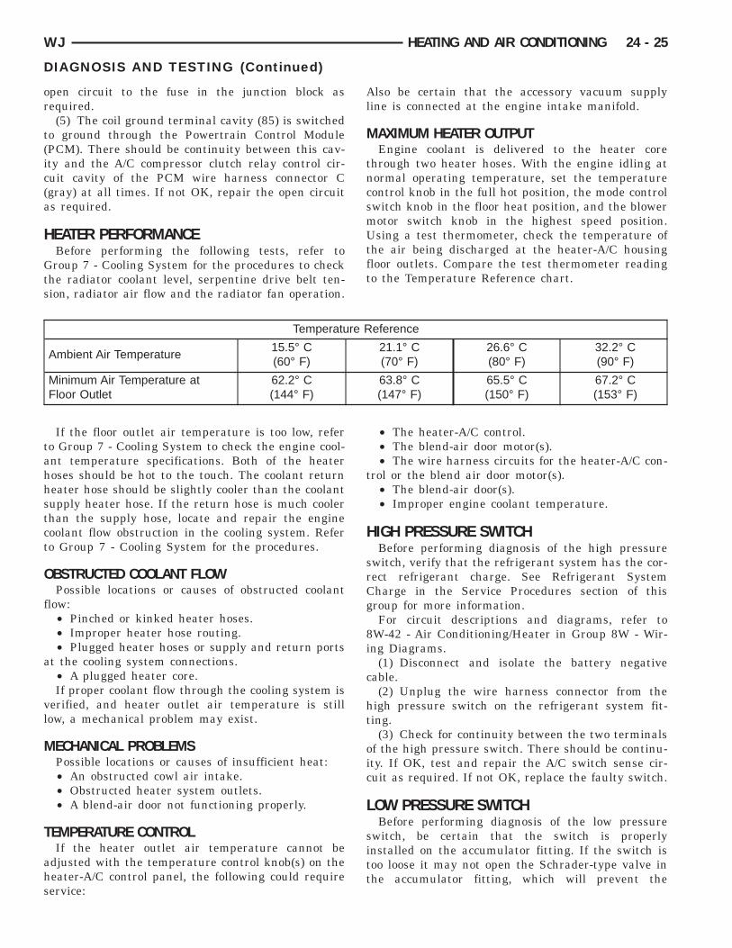
or
t(ic(a
H
Gts
tahhstct
O
f
a
vl
M
T
ahs
WJ HEATING AND AIR CONDITIONING 24 - 25
DIAGNOSIS AND TESTING (Continued)
pen circuit to the fuse in the junction block asequired.(5) The coil ground terminal cavity (85) is switched
o ground through the Powertrain Control ModulePCM). There should be continuity between this cav-ty and the A/C compressor clutch relay control cir-uit cavity of the PCM wire harness connector Cgray) at all times. If not OK, repair the open circuits required.
EATER PERFORMANCEBefore performing the following tests, refer toroup 7 - Cooling System for the procedures to check
he radiator coolant level, serpentine drive belt ten-ion, radiator air flow and the radiator fan operation.
Also be certain that the accessory vacuum supplyline is connected at the engine intake manifold.
MAXIMUM HEATER OUTPUTEngine coolant is delivered to the heater core
through two heater hoses. With the engine idling atnormal operating temperature, set the temperaturecontrol knob in the full hot position, the mode controlswitch knob in the floor heat position, and the blowermotor switch knob in the highest speed position.Using a test thermometer, check the temperature ofthe air being discharged at the heater-A/C housingfloor outlets. Compare the test thermometer readingto the Temperature Reference chart.
Temperature Reference
Ambient Air Temperature15.5° C(60° F)
21.1° C(70° F)
26.6° C(80° F)
32.2° C(90° F)
Minimum Air Temperature atFloor Outlet
62.2° C(144° F)
63.8° C(147° F)
65.5° C(150° F)
67.2° C(153° F)
If the floor outlet air temperature is too low, refero Group 7 - Cooling System to check the engine cool-nt temperature specifications. Both of the heateroses should be hot to the touch. The coolant returneater hose should be slightly cooler than the coolantupply heater hose. If the return hose is much coolerhan the supply hose, locate and repair the engineoolant flow obstruction in the cooling system. Refero Group 7 - Cooling System for the procedures.
BSTRUCTED COOLANT FLOWPossible locations or causes of obstructed coolant
low:• Pinched or kinked heater hoses.• Improper heater hose routing.• Plugged heater hoses or supply and return ports
t the cooling system connections.• A plugged heater core.If proper coolant flow through the cooling system is
erified, and heater outlet air temperature is stillow, a mechanical problem may exist.
ECHANICAL PROBLEMSPossible locations or causes of insufficient heat:• An obstructed cowl air intake.• Obstructed heater system outlets.• A blend-air door not functioning properly.
EMPERATURE CONTROLIf the heater outlet air temperature cannot be
djusted with the temperature control knob(s) on theeater-A/C control panel, the following could requireervice:
• The heater-A/C control.• The blend-air door motor(s).• The wire harness circuits for the heater-A/C con-
trol or the blend air door motor(s).• The blend-air door(s).• Improper engine coolant temperature.
HIGH PRESSURE SWITCHBefore performing diagnosis of the high pressure
switch, verify that the refrigerant system has the cor-rect refrigerant charge. See Refrigerant SystemCharge in the Service Procedures section of thisgroup for more information.
For circuit descriptions and diagrams, refer to8W-42 - Air Conditioning/Heater in Group 8W - Wir-ing Diagrams.
(1) Disconnect and isolate the battery negativecable.
(2) Unplug the wire harness connector from thehigh pressure switch on the refrigerant system fit-ting.
(3) Check for continuity between the two terminalsof the high pressure switch. There should be continu-ity. If OK, test and repair the A/C switch sense cir-cuit as required. If not OK, replace the faulty switch.
LOW PRESSURE SWITCHBefore performing diagnosis of the low pressure
switch, be certain that the switch is properlyinstalled on the accumulator fitting. If the switch istoo loose it may not open the Schrader-type valve inthe accumulator fitting, which will prevent the
st
rC
8i
c
c
o
sE
i
oipstr
R
WTL
ecpan
riif
ccebc
o
24 - 26 HEATING AND AIR CONDITIONING WJ
DIAGNOSIS AND TESTING (Continued)
witch from correctly monitoring the refrigerant sys-em pressure.
Also verify that the refrigerant system has the cor-ect refrigerant charge. See Refrigerant Systemharge in this group for the procedures.For circuit descriptions and diagrams, refer to
W-42 - Air Conditioning/Heater in Group 8W - Wir-ng Diagrams.
(1) Disconnect and isolate the battery negativeable.(2) Unplug the low pressure switch wire harness
onnector from the switch on the accumulator fitting.(3) Install a jumper wire between the two cavities
f the low pressure switch wire harness connector.(4) Connect a manifold gauge set to the refrigerant
ystem service ports. See Refrigerant System Servicequipment in this group for the procedures.(5) Connect the battery negative cable.(6) Place the heater-A/C mode control switch knob
n any A/C position and start the engine.(7) Check for continuity between the two terminals
f the low pressure switch. There should be continu-ty with a suction pressure reading of 262 kPa (38si) or above, and no continuity with a suction pres-ure reading of 141 kPa (20.5 psi) or below. If OK,est and repair the A/C switch sense circuit asequired. If not OK, replace the faulty switch.
EFRIGERANT SYSTEM LEAKS
ARNING: REVIEW THE WARNINGS AND CAU-IONS IN THE FRONT OF THIS GROUP BEFOREEAK TESTING THE SYSTEM.
If the air conditioning system is not cooling prop-rly, determine if the refrigerant system is fully-harged. See A/C Performance in this group for therocedures. If the refrigerant system is low or empty;leak at a refrigerant line, connector fitting, compo-
ent, or component seal is likely.An electronic leak detector designed for R-134a
efrigerant is recommended for locating and confirm-ng refrigerant system leaks. Refer to the operatingnstructions supplied by the equipment manufactureror proper care and use of this equipment.
An oily residue on or near refrigerant system lines,onnector fittings, components, or component sealsan indicate the general location of a possible refrig-rant leak. However, the exact leak location shoulde confirmed with an electronic leak detector prior toomponent repair or replacement.To detect a leak in the refrigerant system, perform
ne of the following procedures:
SYSTEM EMPTY(1) Evacuate the refrigerant system. See Refriger-
ant System Evacuate in this group for the proce-dures.
(2) Connect and dispense 0.283 kilograms (0.625pounds or 10 ounces) of R-134a refrigerant into theevacuated refrigerant system. See Refrigerant Sys-tem Charge in this group for the procedures.
(3) Position the vehicle in a wind-free work area.This will aid in detecting small leaks.
(4) With the engine not running, use a electronicR-134a leak detector and search for leaks. BecauseR-134a refrigerant is heavier than air, the leak detec-tor probe should be moved slowly along the bottomside of all refrigerant lines, connector fittings andcomponents.
(5) To inspect the evaporator coil for leaks, insertthe electronic leak detector probe into the centerinstrument panel outlet. Set the blower motor switchto the lowest speed position, the A/C button in theOn position, and select the Recirculation Mode.
SYSTEM LOW(1) Position the vehicle in a wind-free work area.
This will aid in detecting small leaks.(2) Bring the refrigerant system up to operating
temperature and pressure. This is done by allowingthe engine to run with the air conditioning systemturned on for five minutes.
(3) With the engine not running, use a electronicR-134a leak detector and search for leaks. BecauseR-134a refrigerant is heavier than air, the leak detec-tor probe should be moved slowly along the bottomside of all refrigerant lines, connector fittings andcomponents.
(4) To inspect the evaporator coil for leaks, insertthe electronic leak detector probe into the centerinstrument panel outlet. Set the blower motor switchto the lowest speed position, the A/C button in theOn position, and select the Recirculation Mode.
VACUUM SYSTEMVacuum control is used to operate the mode doors
in the standard equipment manual temperature con-trol system heater-A/C housing. Testing of the heat-er-A/C mode control switch operation will determineif the vacuum, and electrical controls are functioning.However, it is possible that a vacuum control systemthat operates perfectly at engine idle (high enginevacuum) may not function properly at high enginespeeds or loads (low engine vacuum). This can becaused by leaks in the vacuum system, or a faultyvacuum check valve.
A vacuum system test will help to identify thesource of poor vacuum system performance or vac-uum system leaks. Before starting this test, stop the
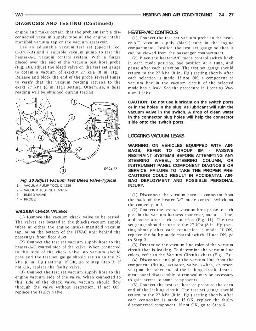
ecm
Chp(tRter
V
Tttp
htpkn
ettr
WJ HEATING AND AIR CONDITIONING 24 - 27
DIAGNOSIS AND TESTING (Continued)
ngine and make certain that the problem isn’t a dis-onnected vacuum supply tube at the engine intakeanifold vacuum tap or the vacuum reservoir.Use an adjustable vacuum test set (Special Tool-3707-B) and a suitable vacuum pump to test theeater-A/C vacuum control system. With a fingerlaced over the end of the vacuum test hose probeFig. 10), adjust the bleed valve on the test set gaugeo obtain a vacuum of exactly 27 kPa (8 in. Hg.).elease and block the end of the probe several times
o verify that the vacuum reading returns to thexact 27 kPa (8 in. Hg.) setting. Otherwise, a falseeading will be obtained during testing.
ACUUM CHECK VALVES(1) Remove the vacuum check valve to be tested.
he valves are located in the (black) vacuum supplyubes at either the engine intake manifold vacuumap, or on the bottom of the HVAC unit behind theassenger front floor duct.(2) Connect the test set vacuum supply hose to the
eater-A/C control side of the valve. When connectedo this side of the check valve, no vacuum shouldass and the test set gauge should return to the 27Pa (8 in. Hg.) setting. If OK, go to step Step 3. Ifot OK, replace the faulty valve.(3) Connect the test set vacuum supply hose to the
ngine vacuum side of the valve. When connected tohis side of the check valve, vacuum should flowhrough the valve without restriction. If not OK,eplace the faulty valve.
Fig. 10 Adjust Vacuum Test Bleed Valve-Typical1 – VACUUM PUMP TOOL C-42892 – VACUUM TEST SET C-37073 – BLEED VALVE4 – PROBE
HEATER-A/C CONTROLS(1) Connect the test set vacuum probe to the heat-
er-A/C vacuum supply (black) tube in the enginecompartment. Position the test set gauge so that itcan be viewed from the passenger compartment.
(2) Place the heater-A/C mode control switch knobin each mode position, one position at a time, andpause after each selection. The test set gauge shouldreturn to the 27 kPa (8 in. Hg.) setting shortly aftereach selection is made. If not OK, a component orvacuum line in the vacuum circuit of the selectedmode has a leak. See the procedure in Locating Vac-uum Leaks.
CAUTION: Do not use lubricant on the switch portsor in the holes in the plug, as lubricant will ruin thevacuum valve in the switch. A drop of clean waterin the connector plug holes will help the connectorslide onto the switch ports.
LOCATING VACUUM LEAKS
WARNING: ON VEHICLES EQUIPPED WITH AIR-BAGS, REFER TO GROUP 8M - PASSIVERESTRAINT SYSTEMS BEFORE ATTEMPTING ANYSTEERING WHEEL, STEERING COLUMN, ORINSTRUMENT PANEL COMPONENT DIAGNOSIS ORSERVICE. FAILURE TO TAKE THE PROPER PRE-CAUTIONS COULD RESULT IN ACCIDENTAL AIR-BAG DEPLOYMENT AND POSSIBLE PERSONALINJURY.
(1) Disconnect the vacuum harness connector fromthe back of the heater-A/C mode control switch onthe control panel.
(2) Connect the test set vacuum hose probe to eachport in the vacuum harness connector, one at a time,and pause after each connection (Fig. 11). The testset gauge should return to the 27 kPa (8 in. Hg.) set-ting shortly after each connection is made. If OK,replace the faulty mode control switch. If not OK, goto Step 3.
(3) Determine the vacuum line color of the vacuumcircuit that is leaking. To determine the vacuum linecolors, refer to the Vacuum Circuits chart (Fig. 12).
(4) Disconnect and plug the vacuum line from thecomponent (fitting, actuator, valve, switch, or reser-voir) on the other end of the leaking circuit. Instru-ment panel disassembly or removal may be necessaryto gain access to some components.
(5) Connect the test set hose or probe to the openend of the leaking circuit. The test set gauge shouldreturn to the 27 kPa (8 in. Hg.) setting shortly aftereach connection is made. If OK, replace the faultydisconnected component. If not OK, go to Step 6.
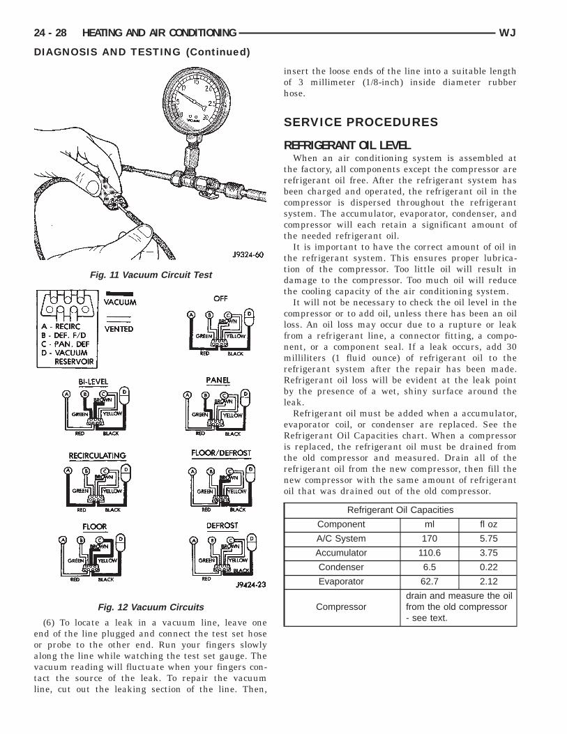
eoavtl
24 - 28 HEATING AND AIR CONDITIONING WJ
DIAGNOSIS AND TESTING (Continued)
(6) To locate a leak in a vacuum line, leave onend of the line plugged and connect the test set hoser probe to the other end. Run your fingers slowlylong the line while watching the test set gauge. Theacuum reading will fluctuate when your fingers con-act the source of the leak. To repair the vacuumine, cut out the leaking section of the line. Then,
Fig. 11 Vacuum Circuit Test
Fig. 12 Vacuum Circuits
insert the loose ends of the line into a suitable lengthof 3 millimeter (1/8-inch) inside diameter rubberhose.
SERVICE PROCEDURES
REFRIGERANT OIL LEVELWhen an air conditioning system is assembled at
the factory, all components except the compressor arerefrigerant oil free. After the refrigerant system hasbeen charged and operated, the refrigerant oil in thecompressor is dispersed throughout the refrigerantsystem. The accumulator, evaporator, condenser, andcompressor will each retain a significant amount ofthe needed refrigerant oil.
It is important to have the correct amount of oil inthe refrigerant system. This ensures proper lubrica-tion of the compressor. Too little oil will result indamage to the compressor. Too much oil will reducethe cooling capacity of the air conditioning system.
It will not be necessary to check the oil level in thecompressor or to add oil, unless there has been an oilloss. An oil loss may occur due to a rupture or leakfrom a refrigerant line, a connector fitting, a compo-nent, or a component seal. If a leak occurs, add 30milliliters (1 fluid ounce) of refrigerant oil to therefrigerant system after the repair has been made.Refrigerant oil loss will be evident at the leak pointby the presence of a wet, shiny surface around theleak.
Refrigerant oil must be added when a accumulator,evaporator coil, or condenser are replaced. See theRefrigerant Oil Capacities chart. When a compressoris replaced, the refrigerant oil must be drained fromthe old compressor and measured. Drain all of therefrigerant oil from the new compressor, then fill thenew compressor with the same amount of refrigerantoil that was drained out of the old compressor.
Refrigerant Oil Capacities
Component ml fl oz
A/C System 170 5.75
Accumulator 110.6 3.75
Condenser 6.5 0.22
Evaporator 62.7 2.12
Compressordrain and measure the oilfrom the old compressor- see text.
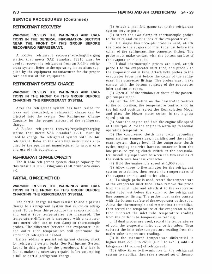
R
WTNR
suepc
R
WTC
liCc
surpa
R
te
P
WTC
ceattpaa
fLfa
WJ HEATING AND AIR CONDITIONING 24 - 29
SERVICE PROCEDURES (Continued)
EFRIGERANT RECOVERY
ARNING: REVIEW THE WARNINGS AND CAU-IONS IN THE GENERAL INFORMATION SECTIONEAR THE FRONT OF THIS GROUP BEFOREECOVERING REFRIGERANT.
A R-134a refrigerant recovery/recycling/chargingtation that meets SAE Standard J2210 must besed to recover the refrigerant from an R-134a refrig-rant system. Refer to the operating instructions sup-lied by the equipment manufacturer for the properare and use of this equipment.
EFRIGERANT SYSTEM CHARGE
ARNING: REVIEW THE WARNINGS AND CAU-IONS IN THE FRONT OF THIS GROUP BEFOREHARGING THE REFRIGERANT SYSTEM.
After the refrigerant system has been tested foreaks and evacuated, a refrigerant charge can benjected into the system. See Refrigerant Chargeapacity for the proper amount of the refrigerantharge.A R-134a refrigerant recovery/recycling/charging
tation that meets SAE Standard J2210 must besed to charge the refrigerant system with R-134aefrigerant. Refer to the operating instructions sup-lied by the equipment manufacturer for proper carend use of this equipment.
EFRIGERANT CHARGE CAPACITYThe R-134a refrigerant system charge capacity for
his vehicle is 0.680 kilograms (1.50 pounds/24 ounc-s).
ARTIAL CHARGE METHOD
ARNING: REVIEW THE WARNINGS AND CAU-IONS IN THE FRONT OF THIS GROUP BEFOREHARGING THE REFRIGERANT SYSTEM.
The partial charge method is used to add a partialharge to a refrigerant system that is low on refrig-rant. To perform this procedure the evaporator inletnd outlet tube temperatures are measured. Theemperature difference is measured with a tempera-ure meter with one or two clamp-on thermocouplerobes. The difference between the evaporator inletnd outlet tube temperatures will determine themount of refrigerant needed.Before adding a partial refrigerant charge, check
or refrigerant system leaks. See Refrigerant Systemeaks in this group for the procedures. If a leak is
ound, make the necessary repairs before attemptingfull or partial refrigerant charge.
(1) Attach a manifold gauge set to the refrigerantsystem service ports.
(2) Attach the two clamp-on thermocouple probesto the inlet and outlet tubes of the evaporator coil.
a. If a single thermocouple probe is used, attachthe probe to the evaporator inlet tube just before thecollar of the refrigerant line connector fitting. Theprobe must make contact with the bottom surface ofthe evaporator inlet tube.
b. If dual thermocouple probes are used, attachprobe 1 to the evaporator inlet tube, and probe 2 tothe evaporator outlet tube. Attach both probes to theevaporator tubes just before the collar of the refrig-erant line connector fittings. The probes must makecontact with the bottom surfaces of the evaporatorinlet and outlet tubes.
(3) Open all of the windows or doors of the passen-ger compartment.
(4) Set the A/C button on the heater-A/C controlsto the on position, the temperature control knob inthe full cool position, select the Recirculation Mode,and place the blower motor switch in the highestspeed position.
(5) Start the engine and hold the engine idle speedat 1,000 rpm. Allow the engine to warm up to normaloperating temperature.
(6) The compressor clutch may cycle, dependingupon ambient temperature, humidity, and the refrig-erant system charge level. If the compressor clutchcycles, unplug the wire harness connector from thelow pressure cycling clutch switch on the accumula-tor. Install a jumper wire between the two cavities ofthe switch wire harness connector.
(7) Hold the engine idle speed at 1,000 rpm.(8) Allow three to five minutes for the refrigerant
system to stabilize, then record the temperatures ofthe evaporator inlet and outlet tubes.
a. If a single probe is used, record the temperatureof the evaporator inlet tube. Then remove the probefrom the inlet tube and attach it to the evaporatoroutlet tube just before the collar of the refrigerantline connector fitting. The probe must make contactwith the bottom surface of the evaporator outlet tube.Allow the thermocouple and meter time to stabilize,then record the temperature of the evaporator outlettube. Subtract the inlet tube temperature readingfrom the outlet tube temperature reading.
b. If dual probes are used, record the temperaturesof both the evaporator inlet and outlet tubes. Thensubtract the inlet tube temperature reading from theoutlet tube temperature reading.
(9) If the measured temperature differential ishigher than 22° C to 26° C (40° F to 47° F), add 0.4kilograms (14 ounces) of refrigerant.
(10) Allow three to five minutes for the refrigerantsystem to stabilize, then take a second set of thermo-
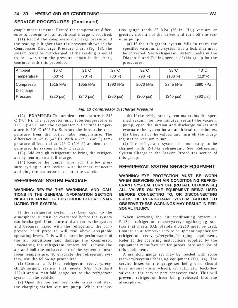
ce
tCstc
C1apdpp
a
sa
R
WTNU
acapotEart
cJs
t
Dis
24 - 30 HEATING AND AIR CONDITIONING WJ
SERVICE PROCEDURES (Continued)
ouple measurements. Record the temperature differ-nce to determine if an additional charge is required.(11) Record the compressor discharge pressure. If
he reading is higher than the pressure shown in theompressor Discharge Pressure chart (Fig. 13), theystem could be overcharged. If the reading is equalo, or lower, than the pressure shown in the chart,ontinue with this procedure.
(12) EXAMPLE: The ambient temperature is 21°(70° F). The evaporator inlet tube temperature is
2° C (54° F) and the evaporator outlet tube temper-ture is 10° C (50° F). Subtract the inlet tube tem-erature from the outlet tube temperature. Theifference is -2° C (-4° F). With a -2° C (-4° F) tem-erature differential at 21° C (70° F) ambient tem-erature, the system is fully charged.(13) Add enough refrigerant to bring the refriger-
nt system up to a full charge.(14) Remove the jumper wire from the low pres-
ure cycling clutch switch wire harness connectornd plug the connector back into the switch.
EFRIGERANT SYSTEM EVACUATE
ARNING: REVIEW THE WARNINGS AND CAU-IONS IN THE GENERAL INFORMATION SECTIONEAR THE FRONT OF THIS GROUP BEFORE EVAC-ATING THE SYSTEM.
If the refrigerant system has been open to thetmosphere, it must be evacuated before the systeman be charged. If moisture and air enters the systemnd becomes mixed with the refrigerant, the com-ressor head pressure will rise above acceptableperating levels. This will reduce the performance ofhe air conditioner and damage the compressor.vacuating the refrigerant system will remove their and boil the moisture out of the system at nearoom temperature. To evacuate the refrigerant sys-em, use the following procedure:
(1) Connect a R-134a refrigerant recovery/recy-ling/charging station that meets SAE Standard2210 and a manifold gauge set to the refrigerantystem of the vehicle.(2) Open the low and high side valves and start
he charging station vacuum pump. When the suc-
Ambient 16°C 21°C 2
Temperature (60°F) (70°F) (8
Compressor 1515 kPa 1655 kPa 179
Discharge
Pressure (220 psi) (240 psi) (26
Fig. 13 Compressor
tion gauge reads 88 kPa (26 in. Hg.) vacuum orgreater, close all of the valves and turn off the vac-uum pump.
(a) If the refrigerant system fails to reach thespecified vacuum, the system has a leak that mustbe corrected. See Refrigerant System Leaks in theDiagnosis and Testing section of this group for theprocedures.
(b) If the refrigerant system maintains the spec-ified vacuum for five minutes, restart the vacuumpump, open the suction and discharge valves andevacuate the system for an additional ten minutes.(3) Close all of the valves, and turn off the charg-
ing station vacuum pump.(4) The refrigerant system is now ready to be
charged with R-134a refrigerant. See RefrigerantSystem Charge in the Service Procedures section ofthis group.
REFRIGERANT SYSTEM SERVICE EQUIPMENT
WARNING: EYE PROTECTION MUST BE WORNWHEN SERVICING AN AIR CONDITIONING REFRIG-ERANT SYSTEM. TURN OFF (ROTATE CLOCKWISE)ALL VALVES ON THE EQUIPMENT BEING USEDBEFORE CONNECTING TO, OR DISCONNECTINGFROM THE REFRIGERANT SYSTEM. FAILURE TOOBSERVE THESE WARNINGS MAY RESULT IN PER-SONAL INJURY.
When servicing the air conditioning system, aR-134a refrigerant recovery/recycling/charging sta-tion that meets SAE Standard J2210 must be used.Contact an automotive service equipment supplier forrefrigerant recovery/recycling/charging equipment.Refer to the operating instructions supplied by theequipment manufacturer for proper care and use ofthis equipment.
A manifold gauge set may be needed with somerecovery/recycling/charging equipment (Fig. 14). Theservice hoses on the gauge set being used shouldhave manual (turn wheel), or automatic back-flowvalves at the service port connector ends. This willprevent refrigerant from being released into theatmosphere.
32°C 38°C 43°C
) (90°F) (100°F) (110°F)
Pa 2070 kPa 2345 kPa 2690 kPa
si) (300 psi) (340 psi) (390 psi)
charge Pressure
7°C
0°F
0 k
0 p
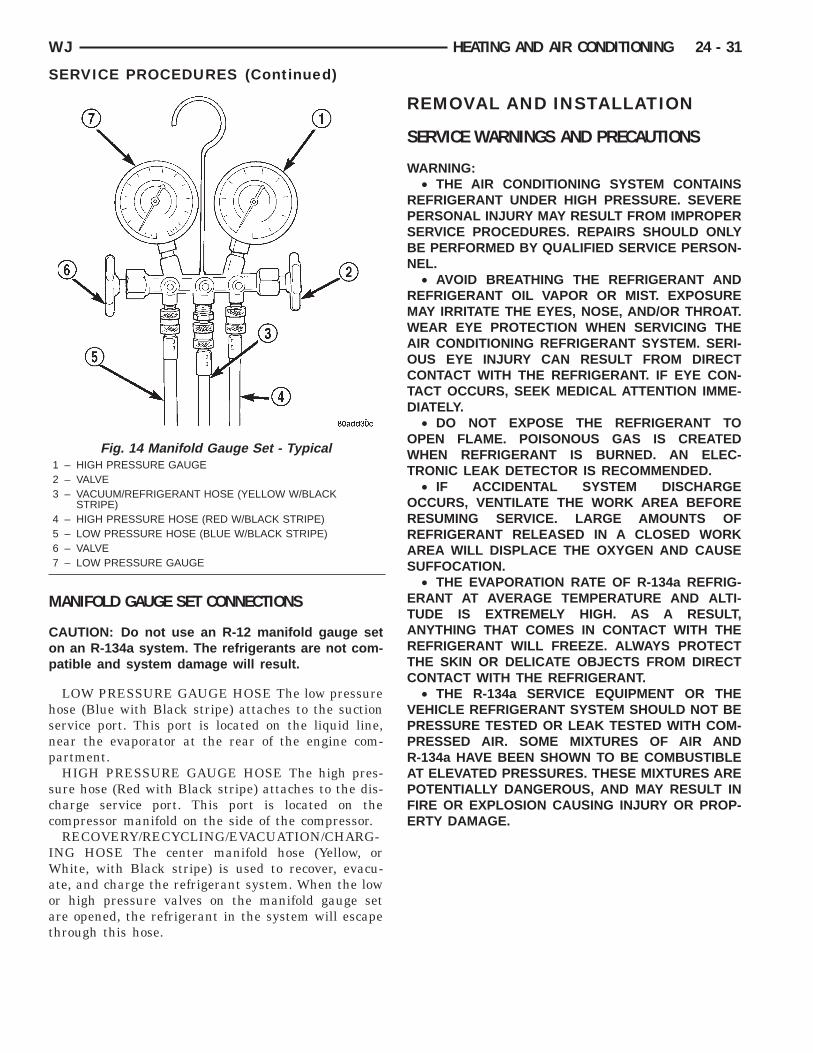
M
Cop
hsnp
scc
IWaoat
WJ HEATING AND AIR CONDITIONING 24 - 31
SERVICE PROCEDURES (Continued)
ANIFOLD GAUGE SET CONNECTIONS
AUTION: Do not use an R-12 manifold gauge setn an R-134a system. The refrigerants are not com-atible and system damage will result.
LOW PRESSURE GAUGE HOSE The low pressureose (Blue with Black stripe) attaches to the suctionervice port. This port is located on the liquid line,ear the evaporator at the rear of the engine com-artment.HIGH PRESSURE GAUGE HOSE The high pres-
ure hose (Red with Black stripe) attaches to the dis-harge service port. This port is located on theompressor manifold on the side of the compressor.RECOVERY/RECYCLING/EVACUATION/CHARG-
NG HOSE The center manifold hose (Yellow, orhite, with Black stripe) is used to recover, evacu-
te, and charge the refrigerant system. When the lowr high pressure valves on the manifold gauge setre opened, the refrigerant in the system will escapehrough this hose.
Fig. 14 Manifold Gauge Set - Typical1 – HIGH PRESSURE GAUGE2 – VALVE3 – VACUUM/REFRIGERANT HOSE (YELLOW W/BLACK
STRIPE)4 – HIGH PRESSURE HOSE (RED W/BLACK STRIPE)5 – LOW PRESSURE HOSE (BLUE W/BLACK STRIPE)6 – VALVE7 – LOW PRESSURE GAUGE
REMOVAL AND INSTALLATION
SERVICE WARNINGS AND PRECAUTIONS
WARNING:• THE AIR CONDITIONING SYSTEM CONTAINS
REFRIGERANT UNDER HIGH PRESSURE. SEVEREPERSONAL INJURY MAY RESULT FROM IMPROPERSERVICE PROCEDURES. REPAIRS SHOULD ONLYBE PERFORMED BY QUALIFIED SERVICE PERSON-NEL.
• AVOID BREATHING THE REFRIGERANT ANDREFRIGERANT OIL VAPOR OR MIST. EXPOSUREMAY IRRITATE THE EYES, NOSE, AND/OR THROAT.WEAR EYE PROTECTION WHEN SERVICING THEAIR CONDITIONING REFRIGERANT SYSTEM. SERI-OUS EYE INJURY CAN RESULT FROM DIRECTCONTACT WITH THE REFRIGERANT. IF EYE CON-TACT OCCURS, SEEK MEDICAL ATTENTION IMME-DIATELY.
• DO NOT EXPOSE THE REFRIGERANT TOOPEN FLAME. POISONOUS GAS IS CREATEDWHEN REFRIGERANT IS BURNED. AN ELEC-TRONIC LEAK DETECTOR IS RECOMMENDED.
• IF ACCIDENTAL SYSTEM DISCHARGEOCCURS, VENTILATE THE WORK AREA BEFORERESUMING SERVICE. LARGE AMOUNTS OFREFRIGERANT RELEASED IN A CLOSED WORKAREA WILL DISPLACE THE OXYGEN AND CAUSESUFFOCATION.
• THE EVAPORATION RATE OF R-134a REFRIG-ERANT AT AVERAGE TEMPERATURE AND ALTI-TUDE IS EXTREMELY HIGH. AS A RESULT,ANYTHING THAT COMES IN CONTACT WITH THEREFRIGERANT WILL FREEZE. ALWAYS PROTECTTHE SKIN OR DELICATE OBJECTS FROM DIRECTCONTACT WITH THE REFRIGERANT.
• THE R-134a SERVICE EQUIPMENT OR THEVEHICLE REFRIGERANT SYSTEM SHOULD NOT BEPRESSURE TESTED OR LEAK TESTED WITH COM-PRESSED AIR. SOME MIXTURES OF AIR ANDR-134a HAVE BEEN SHOWN TO BE COMBUSTIBLEAT ELEVATED PRESSURES. THESE MIXTURES AREPOTENTIALLY DANGEROUS, AND MAY RESULT INFIRE OR EXPLOSION CAUSING INJURY OR PROP-ERTY DAMAGE.
C
fw
dr
R
R
wa
teor
frrcsa
a
rvt
ot
fw
aai
m
brnl
ta
wv
24 - 32 HEATING AND AIR CONDITIONING WJ
REMOVAL AND INSTALLATION (Continued)
AUTION:• Liquid refrigerant is corrosive to metal sur-
aces. Follow the operating instructions suppliedith the service equipment being used.• Never add R-12 to a refrigerant system
esigned to use R-134a. Damage to the system willesult.
• R-12 refrigerant oil must not be mixed with-134a refrigerant oil. They are not compatible.• Do not use R-12 equipment or parts on the
-134a system. Damage to the system will result.• Do not overcharge the refrigerant system. This
ill cause excessive compressor head pressurend can cause noise and system failure.• Recover the refrigerant before opening any fit-
ing or connection. Open the fittings with caution,ven after the system has been discharged. Neverpen or loosen a connection before recovering theefrigerant.
• Do not remove the secondary retention cliprom any spring-lock coupler connection while theefrigerant system is under pressure. Recover theefrigerant before removing the secondary retentionlip. Open the fittings with caution, even after theystem has been discharged. Never open or loosenconnection before recovering the refrigerant.• The refrigerant system must always be evacu-
ted before charging.• Do not open the refrigerant system or uncap a
eplacement component until you are ready to ser-ice the system. This will prevent contamination inhe system.
• Before disconnecting a component, clean theutside of the fittings thoroughly to prevent con-
amination from entering the refrigerant system.• Immediately after disconnecting a component
rom the refrigerant system, seal the open fittingsith a cap or plug.• Before connecting an open refrigerant fitting,
lways install a new seal or gasket. Coat the fittingnd seal with clean refrigerant oil before connect-
ng.• Do not remove the sealing caps from a replace-ent component until it is to be installed.• When installing a refrigerant line, avoid sharp
ends that may restrict refrigerant flow. Position theefrigerant lines away from exhaust system compo-ents or any sharp edges, which may damage the
ine.• Tighten refrigerant fittings only to the specified
orque. The aluminum fittings used in the refriger-nt system will not tolerate overtightening.• When disconnecting a refrigerant fitting, use a
rench on both halves of the fitting. This will pre-ent twisting of the refrigerant lines or tubes.
• Refrigerant oil will absorb moisture from theatmosphere if left uncapped. Do not open a con-tainer of refrigerant oil until you are ready to use it.Replace the cap on the oil container immediatelyafter using. Store refrigerant oil only in a clean, air-tight, and moisture-free container.
• Keep service tools and the work area clean.Contamination of the refrigerant system throughcareless work habits must be avoided.
COOLING SYSTEM REQUIREMENTSTo maintain the performance level of the heating-
air conditioning system, the engine cooling systemmust be properly maintained. The use of a bugscreen is not recommended. Any obstructions in frontof the radiator or condenser will reduce the perfor-mance of the air conditioning and engine cooling sys-tems.
The engine cooling system includes the heater coreand the heater hoses. Refer to Group 7 - Cooling Sys-tem for more information before the opening of, orattempting any service to the engine cooling system.
REFRIGERANT HOSES/LINES/TUBESPRECAUTIONS
Kinks or sharp bends in the refrigerant plumbingwill reduce the capacity of the entire system. Highpressures are produced in the system when it is oper-ating. Extreme care must be exercised to make surethat all refrigerant system connections are pressuretight.
A good rule for the flexible hose refrigerant lines isto keep the radius of all bends at least ten times thediameter of the hose. Sharp bends will reduce theflow of refrigerant. The flexible hose lines should berouted so they are at least 80 millimeters (3 inches)from the exhaust manifold. It is a good practice toinspect all flexible refrigerant system hose lines atleast once a year to make sure they are in good con-dition and properly routed.
There are two types of refrigerant fittings:• All fittings with O-rings need to be coated with
refrigerant oil before installation. Use only O-ringsthat are the correct size and approved for use withR-134a refrigerant. Failure to do so may result in aleak.
• Refrigerant line connections with Stat-O sealtype gaskets cannot be serviced with O-rings. Thegaskets are not reusable and should be replaced anytime the connection has been opened for service.
Using the proper tools when making a refrigerantplumbing connection is very important. Impropertools or improper use of the tools can damage therefrigerant fittings. Always use two wrenches whenloosening or tightening tube fittings. Use one wrench
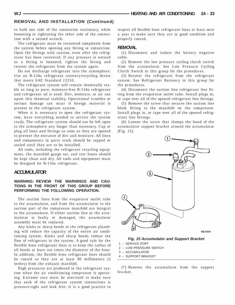
tlt
tOear
Ut
bausp
trtptas
mbb
A
WTP
tstma
itffaIbi
titp
WJ HEATING AND AIR CONDITIONING 24 - 33
REMOVAL AND INSTALLATION (Continued)
o hold one side of the connection stationary, whileoosening or tightening the other side of the connec-ion with a second wrench.
The refrigerant must be recovered completely fromhe system before opening any fitting or connection.pen the fittings with caution, even after the refrig-rant has been recovered. If any pressure is noticeds a fitting is loosened, tighten the fitting andecover the refrigerant from the system again.Do not discharge refrigerant into the atmosphere.se an R-134a refrigerant recovery/recycling device
hat meets SAE Standard J2210.The refrigerant system will remain chemically sta-
le as long as pure, moisture-free R-134a refrigerantnd refrigerant oil is used. Dirt, moisture, or air canpset this chemical stability. Operational troubles orerious damage can occur if foreign material isresent in the refrigerant system.When it is necessary to open the refrigerant sys-
em, have everything needed to service the systemeady. The refrigerant system should not be left openo the atmosphere any longer than necessary. Cap orlug all lines and fittings as soon as they are openedo prevent the entrance of dirt and moisture. All linesnd components in parts stock should be capped orealed until they are to be installed.All tools, including the refrigerant recycling equip-ent, the manifold gauge set, and test hoses should
e kept clean and dry. All tools and equipment muste designed for R-134a refrigerant.
CCUMULATOR
ARNING: REVIEW THE WARNINGS AND CAU-IONS IN THE FRONT OF THIS GROUP BEFOREERFORMING THE FOLLOWING OPERATION.
The suction lines from the evaporator outlet tubeo the accumulator, and from the accumulator to theuction port of the compressor manifold are integralo the accumulator. If either suction line or the accu-ulator is faulty or damaged, the accumulator
ssembly must be replaced.Any kinks or sharp bends in the refrigerant plumb-
ng will reduce the capacity of the entire air condi-ioning system. Kinks and sharp bends reduce thelow of refrigerant in the system. A good rule for thelexible hose refrigerant lines is to keep the radius ofll bends at least ten times the diameter of the hose.n addition, the flexible hose refrigerant lines shoulde routed so they are at least 80 millimeters (3nches) from the exhaust manifold.
High pressures are produced in the refrigerant sys-em when the air conditioning compressor is operat-ng. Extreme care must be exercised to make surehat each of the refrigerant system connections isressure-tight and leak free. It is a good practice to
inspect all flexible hose refrigerant lines at least oncea year to make sure they are in good condition andproperly routed.
REMOVAL(1) Disconnect and isolate the battery negative
cable.(2) Remove the low pressure cycling clutch switch
from the accumulator. See Low Pressure CyclingClutch Switch in this group for the procedures.
(3) Recover the refrigerant from the refrigerantsystem. See Refrigerant Recovery in this group forthe procedures.
(4) Disconnect the suction line refrigerant line fit-ting from the evaporator outlet tube. Install plugs in,or tape over all of the opened refrigerant line fittings.
(5) Remove the screw that secures the suction lineblock fitting to the manifold on the compressor.Install plugs in, or tape over all of the opened refrig-erant line fittings.
(6) Loosen the screw that clamps the band of theaccumulator support bracket around the accumulator(Fig. 15).
(7) Remove the accumulator from the supportbracket.
Fig. 15 Accumulator and Support Bracket1 – SERVICE PORT2 – LOW PRESSURE SWITCH3 – ACCUMULATOR4 – SUPPORT BRACKET
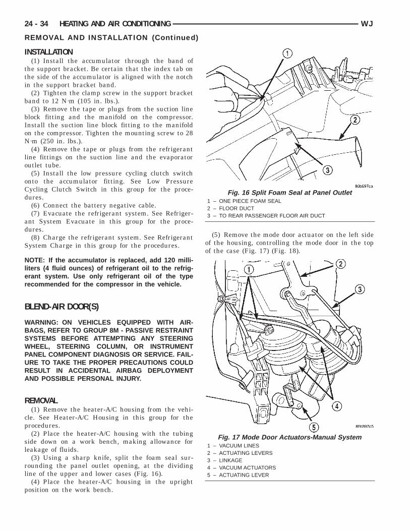
I
tti
b
bIoN
lo
oCd
ad
S
Nler
B
WBSWPURA
R
cp
sl
rl
p
24 - 34 HEATING AND AIR CONDITIONING WJ
REMOVAL AND INSTALLATION (Continued)
NSTALLATION(1) Install the accumulator through the band of
he support bracket. Be certain that the index tab onhe side of the accumulator is aligned with the notchn the support bracket band.
(2) Tighten the clamp screw in the support bracketand to 12 N·m (105 in. lbs.).(3) Remove the tape or plugs from the suction line
lock fitting and the manifold on the compressor.nstall the suction line block fitting to the manifoldn the compressor. Tighten the mounting screw to 28·m (250 in. lbs.).(4) Remove the tape or plugs from the refrigerant
ine fittings on the suction line and the evaporatorutlet tube.(5) Install the low pressure cycling clutch switch
nto the accumulator fitting. See Low Pressureycling Clutch Switch in this group for the proce-ures.(6) Connect the battery negative cable.(7) Evacuate the refrigerant system. See Refriger-
nt System Evacuate in this group for the proce-ures.(8) Charge the refrigerant system. See Refrigerant
ystem Charge in this group for the procedures.
OTE: If the accumulator is replaced, add 120 milli-iters (4 fluid ounces) of refrigerant oil to the refrig-rant system. Use only refrigerant oil of the typeecommended for the compressor in the vehicle.
LEND-AIR DOOR(S)
ARNING: ON VEHICLES EQUIPPED WITH AIR-AGS, REFER TO GROUP 8M - PASSIVE RESTRAINTYSTEMS BEFORE ATTEMPTING ANY STEERINGHEEL, STEERING COLUMN, OR INSTRUMENT
ANEL COMPONENT DIAGNOSIS OR SERVICE. FAIL-RE TO TAKE THE PROPER PRECAUTIONS COULDESULT IN ACCIDENTAL AIRBAG DEPLOYMENTND POSSIBLE PERSONAL INJURY.
EMOVAL(1) Remove the heater-A/C housing from the vehi-
le. See Heater-A/C Housing in this group for therocedures.(2) Place the heater-A/C housing with the tubing
ide down on a work bench, making allowance foreakage of fluids.
(3) Using a sharp knife, split the foam seal sur-ounding the panel outlet opening, at the dividingine of the upper and lower cases (Fig. 16).
(4) Place the heater-A/C housing in the uprightosition on the work bench.
(5) Remove the mode door actuator on the left sideof the housing, controlling the mode door in the topof the case (Fig. 17) (Fig. 18).
Fig. 16 Split Foam Seal at Panel Outlet1 – ONE PIECE FOAM SEAL2 – FLOOR DUCT3 – TO REAR PASSENGER FLOOR AIR DUCT
Fig. 17 Mode Door Actuators-Manual System1 – VACUUM LINES2 – ACTUATING LEVERS3 – LINKAGE4 – VACUUM ACTUATORS5 – ACTUATING LEVER
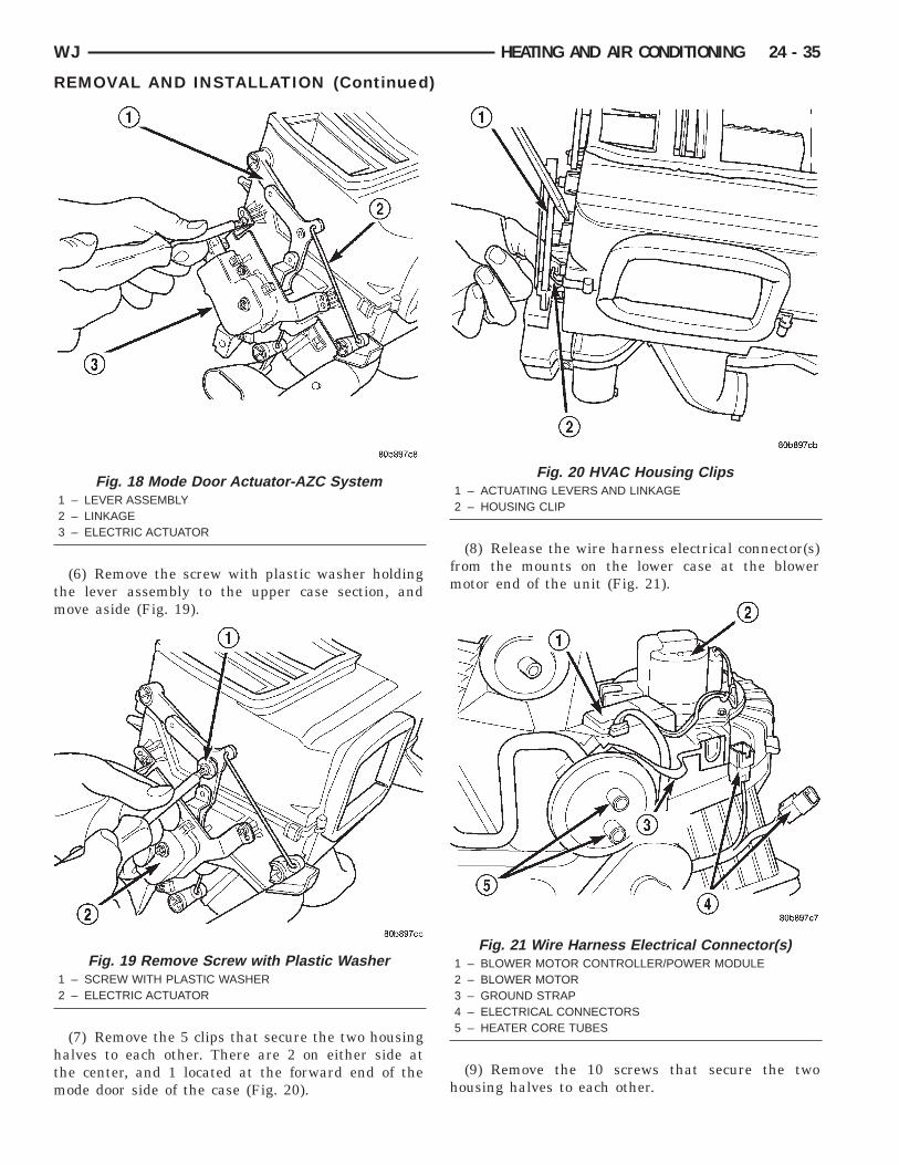
tm
htm
WJ HEATING AND AIR CONDITIONING 24 - 35
REMOVAL AND INSTALLATION (Continued)
(6) Remove the screw with plastic washer holdinghe lever assembly to the upper case section, andove aside (Fig. 19).
(7) Remove the 5 clips that secure the two housingalves to each other. There are 2 on either side athe center, and 1 located at the forward end of theode door side of the case (Fig. 20).
Fig. 18 Mode Door Actuator-AZC System1 – LEVER ASSEMBLY2 – LINKAGE3 – ELECTRIC ACTUATOR
Fig. 19 Remove Screw with Plastic Washer1 – SCREW WITH PLASTIC WASHER2 – ELECTRIC ACTUATOR
(8) Release the wire harness electrical connector(s)from the mounts on the lower case at the blowermotor end of the unit (Fig. 21).
(9) Remove the 10 screws that secure the twohousing halves to each other.
Fig. 20 HVAC Housing Clips1 – ACTUATING LEVERS AND LINKAGE2 – HOUSING CLIP
Fig. 21 Wire Harness Electrical Connector(s)1 – BLOWER MOTOR CONTROLLER/POWER MODULE2 – BLOWER MOTOR3 – GROUND STRAP4 – ELECTRICAL CONNECTORS5 – HEATER CORE TUBES
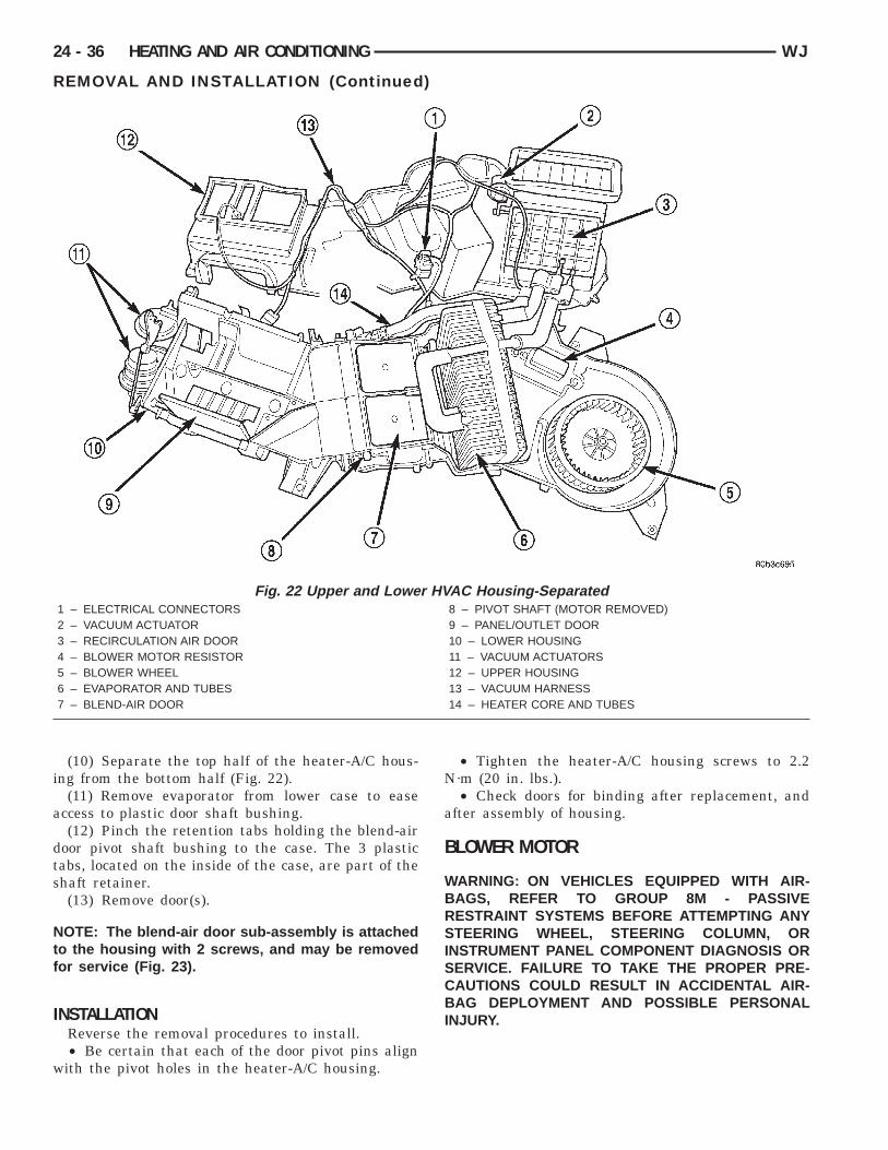
i
a
dts
Ntf
I
w
24 - 36 HEATING AND AIR CONDITIONING WJ
REMOVAL AND INSTALLATION (Continued)
(10) Separate the top half of the heater-A/C hous-ng from the bottom half (Fig. 22).
(11) Remove evaporator from lower case to easeccess to plastic door shaft bushing.(12) Pinch the retention tabs holding the blend-air
oor pivot shaft bushing to the case. The 3 plasticabs, located on the inside of the case, are part of thehaft retainer.(13) Remove door(s).
OTE: The blend-air door sub-assembly is attachedo the housing with 2 screws, and may be removedor service (Fig. 23).
NSTALLATIONReverse the removal procedures to install.• Be certain that each of the door pivot pins alignith the pivot holes in the heater-A/C housing.
Fig. 22 Upper and Lower1 – ELECTRICAL CONNECTORS2 – VACUUM ACTUATOR3 – RECIRCULATION AIR DOOR4 – BLOWER MOTOR RESISTOR5 – BLOWER WHEEL6 – EVAPORATOR AND TUBES7 – BLEND-AIR DOOR
• Tighten the heater-A/C housing screws to 2.2N·m (20 in. lbs.).
• Check doors for binding after replacement, andafter assembly of housing.
BLOWER MOTOR
WARNING: ON VEHICLES EQUIPPED WITH AIR-BAGS, REFER TO GROUP 8M - PASSIVERESTRAINT SYSTEMS BEFORE ATTEMPTING ANYSTEERING WHEEL, STEERING COLUMN, ORINSTRUMENT PANEL COMPONENT DIAGNOSIS ORSERVICE. FAILURE TO TAKE THE PROPER PRE-CAUTIONS COULD RESULT IN ACCIDENTAL AIR-BAG DEPLOYMENT AND POSSIBLE PERSONALINJURY.
C Housing-Separated8 – PIVOT SHAFT (MOTOR REMOVED)9 – PANEL/OUTLET DOOR10 – LOWER HOUSING11 – VACUUM ACTUATORS12 – UPPER HOUSING13 – VACUUM HARNESS14 – HEATER CORE AND TUBES
HVA
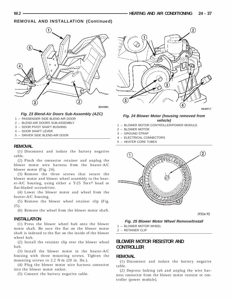
R
c
bb
bef
h
2
I
msw
h
hm
i
WJ HEATING AND AIR CONDITIONING 24 - 37
REMOVAL AND INSTALLATION (Continued)
EMOVAL(1) Disconnect and isolate the battery negative
able.(2) Pinch the connector retainer and unplug the
lower motor wire harness from the heater-A/Clower motor (Fig. 24).(3) Remove the three screws that secure the
lower motor and blower wheel assembly to the heat-r-A/C housing, using either a T-25 Torxt head orlat-bladed screwdriver.
(4) Lower the blower motor and wheel from theeater-A/C housing.(5) Remove the blower wheel retainer clip (Fig.
5).(6) Remove the wheel from the blower motor shaft.
NSTALLATION(1) Press the blower wheel hub onto the blowerotor shaft. Be sure the flat on the blower motor
haft is indexed to the flat on the inside of the blowerheel hub.(2) Install the retainer clip over the blower wheel
ub.(3) Install the blower motor in the heater-A/C
ousing with three mounting screws. Tighten theounting screws to 2.2 N·m (20 in. lbs.).(4) Plug the blower motor wire harness connector
nto the blower motor socket.(5) Connect the battery negative cable.
Fig. 23 Blend-Air Doors Sub-Assembly (AZC)1 – PASSENGER SIDE BLEND-AIR DOOR2 – BLEND-AIR DOORS SUB-ASSEMBLY3 – DOOR PIVOT SHAFT BUSHING4 – DOOR SHAFT LEVER5 – DRIVER SIDE BLEND-AIR DOOR
BLOWER MOTOR RESISTOR ANDCONTROLLER
REMOVAL(1) Disconnect and isolate the battery negative
cable.(2) Depress locking tab and unplug the wire har-
ness connector from the blower motor resistor or con-troller (power module).
Fig. 24 Blower Motor (housing removed fromvehicle)
1 – BLOWER MOTOR CONTROLLER/POWER MODULE2 – BLOWER MOTOR3 – GROUND STRAP4 – ELECTRICAL CONNECTORS5 – HEATER CORE TUBES
Fig. 25 Blower Motor Wheel Remove/Install1 – BLOWER MOTOR WHEEL2 – RETAINER CLIP
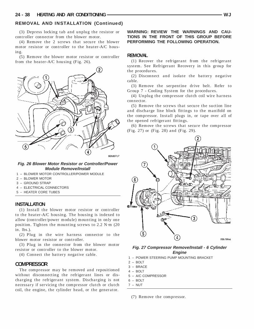
c
mi
f
I
tapi
b
r
C
wcnc
24 - 38 HEATING AND AIR CONDITIONING WJ
REMOVAL AND INSTALLATION (Continued)
(3) Depress locking tab and unplug the resistor orontroller connector from the blower motor.(4) Remove the 2 screws that secure the blowerotor resistor or controller to the heater-A/C hous-
ng.(5) Remove the blower motor resistor or controller
rom the heater-A/C housing (Fig. 26).
NSTALLATION(1) Install the blower motor resistor or controller
o the heater-A/C housing. The housing is indexed tollow (controller/power module) mounting in only oneosition. Tighten the mounting screws to 2.2 N·m (20n. lbs.).
(2) Plug in the wire harness connector to thelower motor resistor or controller.(3) Plug in the connector from the blower motor
esistor or controller to the blower motor.(4) Connect the battery negative cable.
OMPRESSORThe compressor may be removed and repositionedithout disconnecting the refrigerant lines or dis-
harging the refrigerant system. Discharging is notecessary if servicing the compressor clutch or clutchoil, the engine, the cylinder head, or the generator.
Fig. 26 Blower Motor Resistor or Controller/PowerModule Remove/Install
1 – BLOWER MOTOR CONTROLLER/POWER MODULE2 – BLOWER MOTOR3 – GROUND STRAP4 – ELECTRICAL CONNECTORS5 – HEATER CORE TUBES
WARNING: REVIEW THE WARNINGS AND CAU-TIONS IN THE FRONT OF THIS GROUP BEFOREPERFORMING THE FOLLOWING OPERATION.
REMOVAL(1) Recover the refrigerant from the refrigerant
system. See Refrigerant Recovery in this group forthe procedures.
(2) Disconnect and isolate the battery negativecable.
(3) Remove the serpentine drive belt. Refer toGroup 7 - Cooling System for the procedures.
(4) Unplug the compressor clutch coil wire harnessconnector.
(5) Remove the screws that secure the suction lineand discharge line block fittings to the manifold onthe compressor. Install plugs in, or tape over all ofthe opened refrigerant fittings.
(6) Remove the screws that secure the compressor(Fig. 27) or (Fig. 28) and (Fig. 29).
(7) Remove the compressor.
Fig. 27 Compressor Remove/Instal l - 6 CylinderEngine
1 – POWER STEERING PUMP MOUNTING BRACKET2 – BOLT3 – BRACE4 – BOLT5 – A/C COMPRESSOR6 – BOLT7 – NUT
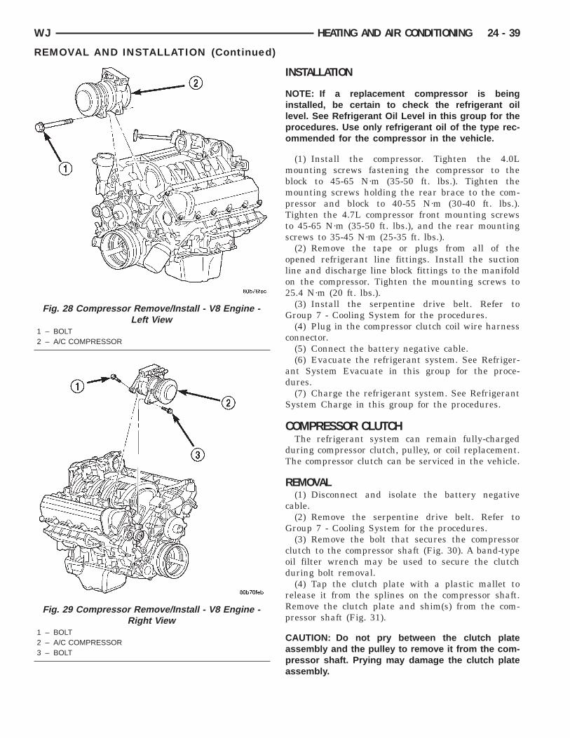
WJ HEATING AND AIR CONDITIONING 24 - 39
REMOVAL AND INSTALLATION (Continued)
INSTALLATION
NOTE: If a replacement compressor is beinginstalled, be certain to check the refrigerant oillevel. See Refrigerant Oil Level in this group for theprocedures. Use only refrigerant oil of the type rec-ommended for the compressor in the vehicle.
(1) Install the compressor. Tighten the 4.0Lmounting screws fastening the compressor to theblock to 45-65 N·m (35-50 ft. lbs.). Tighten themounting screws holding the rear brace to the com-pressor and block to 40-55 N·m (30-40 ft. lbs.).Tighten the 4.7L compressor front mounting screwsto 45-65 N·m (35-50 ft. lbs.), and the rear mountingscrews to 35-45 N·m (25-35 ft. lbs.).
(2) Remove the tape or plugs from all of theopened refrigerant line fittings. Install the suctionline and discharge line block fittings to the manifoldon the compressor. Tighten the mounting screws to25.4 N·m (20 ft. lbs.).
(3) Install the serpentine drive belt. Refer toGroup 7 - Cooling System for the procedures.
(4) Plug in the compressor clutch coil wire harnessconnector.
(5) Connect the battery negative cable.(6) Evacuate the refrigerant system. See Refriger-
ant System Evacuate in this group for the proce-dures.
(7) Charge the refrigerant system. See RefrigerantSystem Charge in this group for the procedures.
COMPRESSOR CLUTCHThe refrigerant system can remain fully-charged
during compressor clutch, pulley, or coil replacement.The compressor clutch can be serviced in the vehicle.
REMOVAL(1) Disconnect and isolate the battery negative
cable.(2) Remove the serpentine drive belt. Refer to
Group 7 - Cooling System for the procedures.(3) Remove the bolt that secures the compressor
clutch to the compressor shaft (Fig. 30). A band-typeoil filter wrench may be used to secure the clutchduring bolt removal.
(4) Tap the clutch plate with a plastic mallet torelease it from the splines on the compressor shaft.Remove the clutch plate and shim(s) from the com-pressor shaft (Fig. 31).
CAUTION: Do not pry between the clutch plateassembly and the pulley to remove it from the com-pressor shaft. Prying may damage the clutch plateassembly.
Fig. 28 Compressor Remove/Install - V8 Engine -Left View
1 – BOLT2 – A/C COMPRESSOR
Fig. 29 Compressor Remove/Install - V8 Engine -Right View
1 – BOLT2 – A/C COMPRESSOR3 – BOLT
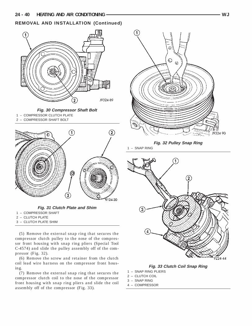
csCp
ci
cfa
24 - 40 HEATING AND AIR CONDITIONING WJ
REMOVAL AND INSTALLATION (Continued)
(5) Remove the external snap ring that secures theompressor clutch pulley to the nose of the compres-or front housing with snap ring pliers (Special Tool-4574) and slide the pulley assembly off of the com-ressor (Fig. 32).(6) Remove the screw and retainer from the clutch
oil lead wire harness on the compressor front hous-ng.
(7) Remove the external snap ring that secures theompressor clutch coil to the nose of the compressorront housing with snap ring pliers and slide the coilssembly off of the compressor (Fig. 33).
Fig. 30 Compressor Shaft Bolt1 – COMPRESSOR CLUTCH PLATE2 – COMPRESSOR SHAFT BOLT
Fig. 31 Clutch Plate and Shim1 – COMPRESSOR SHAFT2 – CLUTCH PLATE3 – CLUTCH PLATE SHIM
Fig. 32 Pulley Snap Ring1 – SNAP RING
Fig. 33 Clutch Coil Snap Ring1 – SNAP RING PLIERS2 – CLUTCH COIL3 – SNAP RING4 – COMPRESSOR
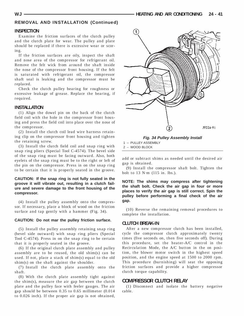
I
asi
aRtisr
er
I
fit
it
soett
Cguc
ss
C
(Tt
aus
s
tpgt
WJ HEATING AND AIR CONDITIONING 24 - 41
REMOVAL AND INSTALLATION (Continued)
NSPECTIONExamine the friction surfaces of the clutch pulley
nd the clutch plate for wear. The pulley and platehould be replaced if there is excessive wear or scor-ng.
If the friction surfaces are oily, inspect the shaftnd nose area of the compressor for refrigerant oil.emove the felt wick from around the shaft inside
he nose of the compressor front housing. If the felts saturated with refrigerant oil, the compressorhaft seal is leaking and the compressor must beeplaced.Check the clutch pulley bearing for roughness or
xcessive leakage of grease. Replace the bearing, ifequired.
NSTALLATION(1) Align the dowel pin on the back of the clutch
ield coil with the hole in the compressor front hous-ng and press the field coil into place over the nose ofhe compressor.
(2) Install the clutch coil lead wire harness retain-ng clip on the compressor front housing and tightenhe retaining screw.
(3) Install the clutch field coil and snap ring withnap ring pliers (Special Tool C-4574). The bevel sidef the snap ring must be facing outward. Also, bothyelets of the snap ring must be to the right or left ofhe pin on the compressor. Press in on the snap ringo be certain that it is properly seated in the groove.
AUTION: If the snap ring is not fully seated in theroove it will vibrate out, resulting in a clutch fail-re and severe damage to the front housing of theompressor.
(4) Install the pulley assembly onto the compres-or. If necessary, place a block of wood on the frictionurface and tap gently with a hammer (Fig. 34).
AUTION: Do not mar the pulley friction surface.
(5) Install the pulley assembly retaining snap ringbevel side outward) with snap ring pliers (Specialool C-4574). Press in on the snap ring to be certainhat it is properly seated in the groove.
(6) If the original clutch plate assembly and pulleyssembly are to be reused, the old shim(s) can besed. If not, place a stack of shim(s) equal to the oldhim(s) on the shaft against the shoulder.(7) Install the clutch plate assembly onto the
haft.(8) With the clutch plate assembly tight against
he shim(s), measure the air gap between the clutchlate and the pulley face with feeler gauges. The airap should be between 0.35 to 0.65 millimeter (0.014o 0.026 inch). If the proper air gap is not obtained,
add or subtract shims as needed until the desired airgap is obtained.
(9) Install the compressor shaft bolt. Tighten thebolt to 13 N·m (115 in. lbs.).
NOTE: The shims may compress after tighteningthe shaft bolt. Check the air gap in four or moreplaces to verify the air gap is still correct. Spin thepulley before performing a final check of the airgap.
(10) Reverse the remaining removal procedures tocomplete the installation.
CLUTCH BREAK-INAfter a new compressor clutch has been installed,
cycle the compressor clutch approximately twentytimes (five seconds on, then five seconds off). Duringthis procedure, set the heater-A/C control in theRecirculation Mode, the A/C button in the on posi-tion, the blower motor switch in the highest speedposition, and the engine speed at 1500 to 2000 rpm.This procedure (burnishing) will seat the opposingfriction surfaces and provide a higher compressorclutch torque capability.
COMPRESSOR CLUTCH RELAY(1) Disconnect and isolate the battery negative
cable.
Fig. 34 Pulley Assembly Install1 – PULLEY ASSEMBLY2 – WOOD BLOCK
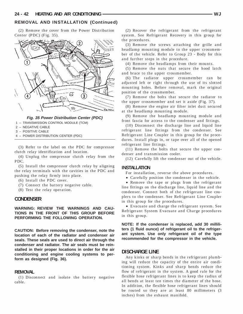
C
c
P
tp
C
WTP
Clscscf
R
c
24 - 42 HEATING AND AIR CONDITIONING WJ
REMOVAL AND INSTALLATION (Continued)
(2) Remove the cover from the Power Distributionenter (PDC) (Fig. 35).
(3) Refer to the label on the PDC for compressorlutch relay identification and location.(4) Unplug the compressor clutch relay from the
DC.(5) Install the compressor clutch relay by aligning
he relay terminals with the cavities in the PDC andushing the relay firmly into place.(6) Install the PDC cover.(7) Connect the battery negative cable.(8) Test the relay operation.
ONDENSER
ARNING: REVIEW THE WARNINGS AND CAU-IONS IN THE FRONT OF THIS GROUP BEFOREERFORMING THE FOLLOWING OPERATION.
AUTION: Before removing the condenser, note theocation of each of the radiator and condenser aireals. These seals are used to direct air through theondenser and radiator. The air seals must be rein-talled in their proper locations in order for the aironditioning and engine cooling systems to per-orm as designed (Fig. 36).
EMOVAL(1) Disconnect and isolate the battery negative
able.
Fig. 35 Power Distribution Center (PDC)1 – TRANSMISSION CONTROL MODULE (TCM)2 – NEGATIVE CABLE3 – POSITIVE CABLE4 – POWER DISTRIBUTION CENTER (PDC)
(2) Recover the refrigerant from the refrigerantsystem. See Refrigerant Recovery in this group forthe procedures.
(3) Remove the screws attaching the grille andheadlamp mounting module to the upper crossmem-ber of the vehicle. Refer to Group 23 - Body for thisand further steps in the procedure.
(4) Remove the headlamps from their mounts.(5) Remove the nuts that secure the hood latch
and brace to the upper crossmember.(6) The radiator upper crossmember can be
adjusted left or right through the use of its slottedmounting holes. Before removal, mark the originalposition of the crossmember.
(7) Remove the bolts that secure the radiator tothe upper crossmember and set it aside (Fig. 37).
(8) Remove the engine air filter inlet duct securedat the headlamp mounting module.
(9) Remove the headlamp mounting module andfront fascia for access to the condenser and fittings.
(10) Disconnect the discharge line and liquid linerefrigerant line fittings from the condenser. SeeRefrigerant Line Coupler in this group for the proce-dures. Install plugs in, or tape over all of the openedrefrigerant line fittings.
(11) Remove the bolts that secure the upper con-denser and transmission cooler.
(12) Carefully lift the condenser out of the vehicle.
INSTALLATIONFor installation, reverse the above procedures.• Carefully position the condenser in the vehicle.• Remove the tape or plugs from the refrigerant
line fittings on the discharge line, liquid line and thecondenser. Connect both of the refrigerant line cou-plers to the condenser. See Refrigerant Line Couplerin this group for the procedures.
• Evacuate and charge the refrigerant system. SeeRefrigerant System Evacuate and Charge proceduresin this group.
NOTE: If the condenser is replaced, add 30 millili-ters (1 fluid ounce) of refrigerant oil to the refriger-ant system. Use only refrigerant oil of the typerecommended for the compressor in the vehicle.
DISCHARGE LINEAny kinks or sharp bends in the refrigerant plumb-
ing will reduce the capacity of the entire air condi-tioning system. Kinks and sharp bends reduce theflow of refrigerant in the system. A good rule for theflexible hose refrigerant lines is to keep the radius ofall bends at least ten times the diameter of the hose.In addition, the flexible hose refrigerant lines shouldbe routed so they are at least 80 millimeters (3inches) from the exhaust manifold.
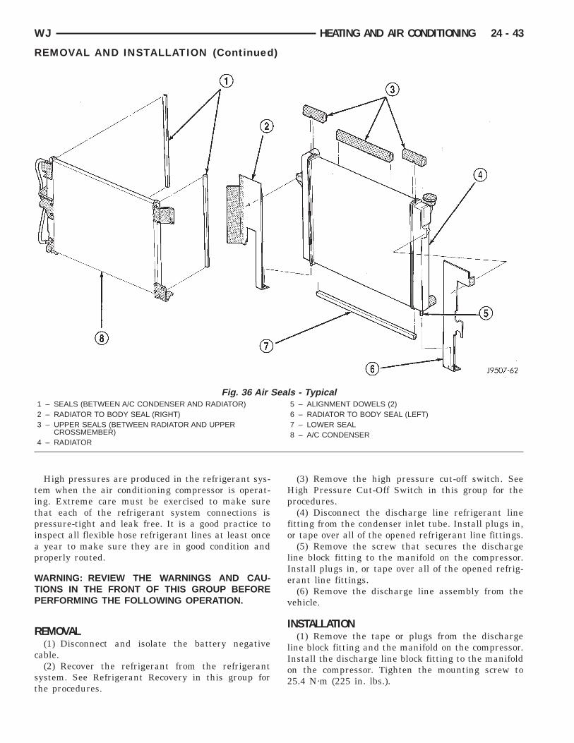
titpiap
WTP
R
c
st
WJ HEATING AND AIR CONDITIONING 24 - 43
REMOVAL AND INSTALLATION (Continued)
High pressures are produced in the refrigerant sys-em when the air conditioning compressor is operat-ng. Extreme care must be exercised to make surehat each of the refrigerant system connections isressure-tight and leak free. It is a good practice tonspect all flexible hose refrigerant lines at least once
year to make sure they are in good condition androperly routed.
ARNING: REVIEW THE WARNINGS AND CAU-IONS IN THE FRONT OF THIS GROUP BEFOREERFORMING THE FOLLOWING OPERATION.
EMOVAL(1) Disconnect and isolate the battery negative
able.(2) Recover the refrigerant from the refrigerant
ystem. See Refrigerant Recovery in this group forhe procedures.
Fig. 36 Air S1 – SEALS (BETWEEN A/C CONDENSER AND RADIATOR)2 – RADIATOR TO BODY SEAL (RIGHT)3 – UPPER SEALS (BETWEEN RADIATOR AND UPPER
CROSSMEMBER)4 – RADIATOR
(3) Remove the high pressure cut-off switch. SeeHigh Pressure Cut-Off Switch in this group for theprocedures.
(4) Disconnect the discharge line refrigerant linefitting from the condenser inlet tube. Install plugs in,or tape over all of the opened refrigerant line fittings.
(5) Remove the screw that secures the dischargeline block fitting to the manifold on the compressor.Install plugs in, or tape over all of the opened refrig-erant line fittings.
(6) Remove the discharge line assembly from thevehicle.
INSTALLATION(1) Remove the tape or plugs from the discharge
line block fitting and the manifold on the compressor.Install the discharge line block fitting to the manifoldon the compressor. Tighten the mounting screw to25.4 N·m (225 in. lbs.).
- Typical5 – ALIGNMENT DOWELS (2)6 – RADIATOR TO BODY SEAL (LEFT)7 – LOWER SEAL8 – A/C CONDENSER
eals
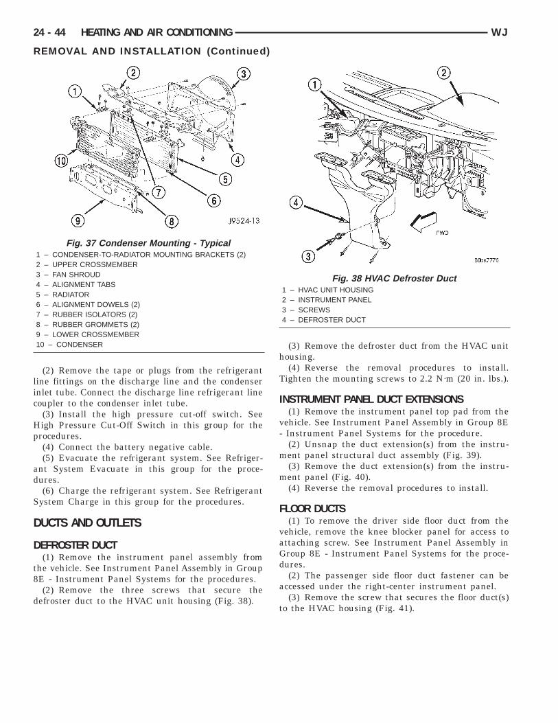
lic
Hp
ad
S
D
D
t8
d
24 - 44 HEATING AND AIR CONDITIONING WJ
REMOVAL AND INSTALLATION (Continued)
(2) Remove the tape or plugs from the refrigerantine fittings on the discharge line and the condensernlet tube. Connect the discharge line refrigerant lineoupler to the condenser inlet tube.(3) Install the high pressure cut-off switch. Seeigh Pressure Cut-Off Switch in this group for therocedures.(4) Connect the battery negative cable.(5) Evacuate the refrigerant system. See Refriger-
nt System Evacuate in this group for the proce-ures.(6) Charge the refrigerant system. See Refrigerant
ystem Charge in this group for the procedures.
UCTS AND OUTLETS
EFROSTER DUCT(1) Remove the instrument panel assembly from
he vehicle. See Instrument Panel Assembly in GroupE - Instrument Panel Systems for the procedures.(2) Remove the three screws that secure the
efroster duct to the HVAC unit housing (Fig. 38).
Fig. 37 Condenser Mounting - Typical1 – CONDENSER-TO-RADIATOR MOUNTING BRACKETS (2)2 – UPPER CROSSMEMBER3 – FAN SHROUD4 – ALIGNMENT TABS5 – RADIATOR6 – ALIGNMENT DOWELS (2)7 – RUBBER ISOLATORS (2)8 – RUBBER GROMMETS (2)9 – LOWER CROSSMEMBER10 – CONDENSER
(3) Remove the defroster duct from the HVAC unithousing.(4) Reverse the removal procedures to install.
Tighten the mounting screws to 2.2 N·m (20 in. lbs.).
INSTRUMENT PANEL DUCT EXTENSIONS(1) Remove the instrument panel top pad from the
vehicle. See Instrument Panel Assembly in Group 8E- Instrument Panel Systems for the procedure.
(2) Unsnap the duct extension(s) from the instru-ment panel structural duct assembly (Fig. 39).
(3) Remove the duct extension(s) from the instru-ment panel (Fig. 40).
(4) Reverse the removal procedures to install.
FLOOR DUCTS(1) To remove the driver side floor duct from the
vehicle, remove the knee blocker panel for access toattaching screw. See Instrument Panel Assembly inGroup 8E - Instrument Panel Systems for the proce-dures.
(2) The passenger side floor duct fastener can beaccessed under the right-center instrument panel.
(3) Remove the screw that secures the floor duct(s)to the HVAC housing (Fig. 41).
Fig. 38 HVAC Defroster Duct1 – HVAC UNIT HOUSING2 – INSTRUMENT PANEL3 – SCREWS4 – DEFROSTER DUCT
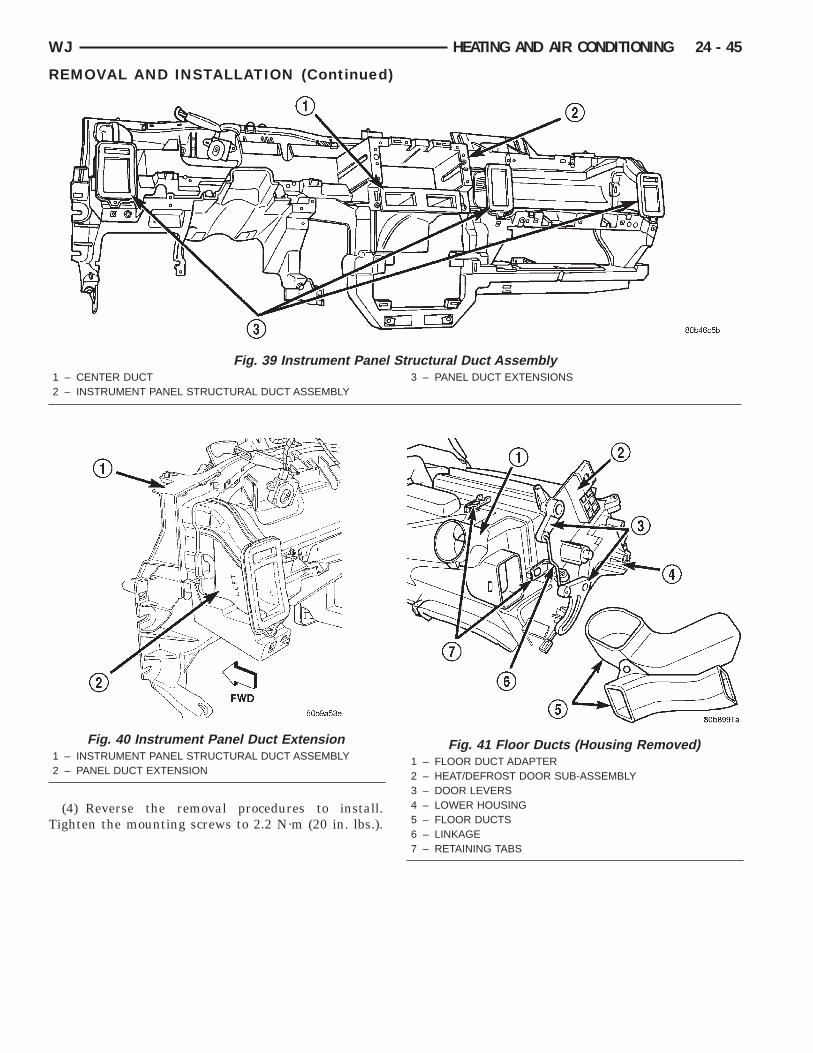
T
WJ HEATING AND AIR CONDITIONING 24 - 45
REMOVAL AND INSTALLATION (Continued)
(4) Reverse the removal procedures to install.ighten the mounting screws to 2.2 N·m (20 in. lbs.).
Fig. 39 Instrument Panel1 – CENTER DUCT2 – INSTRUMENT PANEL STRUCTURAL DUCT ASSEMBLY
Fig. 40 Instrument Panel Duct Extension1 – INSTRUMENT PANEL STRUCTURAL DUCT ASSEMBLY2 – PANEL DUCT EXTENSION
Structural Duct Assembly3 – PANEL DUCT EXTENSIONS
Fig. 41 Floor Ducts (Housing Removed)1 – FLOOR DUCT ADAPTER2 – HEAT/DEFROST DOOR SUB-ASSEMBLY3 – DOOR LEVERS4 – LOWER HOUSING5 – FLOOR DUCTS6 – LINKAGE7 – RETAINING TABS
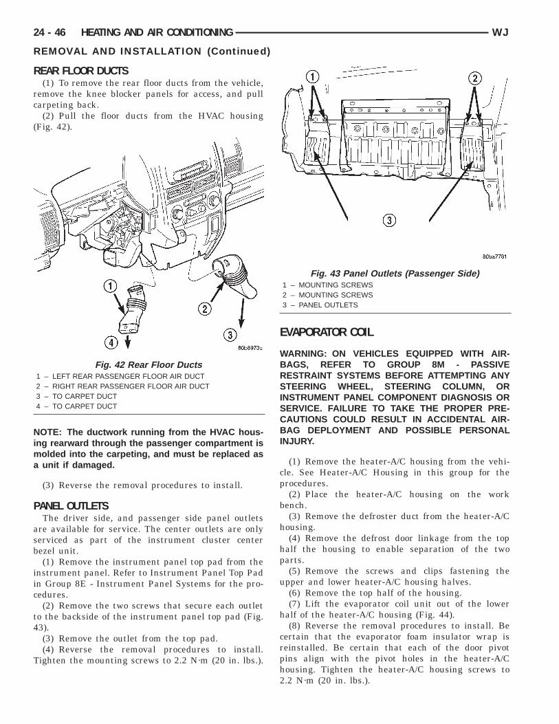
R
rc
(
Nima
P
asb
iic
t4
T
24 - 46 HEATING AND AIR CONDITIONING WJ
REMOVAL AND INSTALLATION (Continued)
EAR FLOOR DUCTS(1) To remove the rear floor ducts from the vehicle,
emove the knee blocker panels for access, and pullarpeting back.(2) Pull the floor ducts from the HVAC housing
Fig. 42).
OTE: The ductwork running from the HVAC hous-ng rearward through the passenger compartment is
olded into the carpeting, and must be replaced asunit if damaged.
(3) Reverse the removal procedures to install.
ANEL OUTLETSThe driver side, and passenger side panel outlets
re available for service. The center outlets are onlyerviced as part of the instrument cluster centerezel unit.(1) Remove the instrument panel top pad from the
nstrument panel. Refer to Instrument Panel Top Padn Group 8E - Instrument Panel Systems for the pro-edures.(2) Remove the two screws that secure each outlet
o the backside of the instrument panel top pad (Fig.3).(3) Remove the outlet from the top pad.(4) Reverse the removal procedures to install.
ighten the mounting screws to 2.2 N·m (20 in. lbs.).
Fig. 42 Rear Floor Ducts1 – LEFT REAR PASSENGER FLOOR AIR DUCT2 – RIGHT REAR PASSENGER FLOOR AIR DUCT3 – TO CARPET DUCT4 – TO CARPET DUCT
EVAPORATOR COIL
WARNING: ON VEHICLES EQUIPPED WITH AIR-BAGS, REFER TO GROUP 8M - PASSIVERESTRAINT SYSTEMS BEFORE ATTEMPTING ANYSTEERING WHEEL, STEERING COLUMN, ORINSTRUMENT PANEL COMPONENT DIAGNOSIS ORSERVICE. FAILURE TO TAKE THE PROPER PRE-CAUTIONS COULD RESULT IN ACCIDENTAL AIR-BAG DEPLOYMENT AND POSSIBLE PERSONALINJURY.
(1) Remove the heater-A/C housing from the vehi-cle. See Heater-A/C Housing in this group for theprocedures.
(2) Place the heater-A/C housing on the workbench.
(3) Remove the defroster duct from the heater-A/Chousing.
(4) Remove the defrost door linkage from the tophalf the housing to enable separation of the twoparts.
(5) Remove the screws and clips fastening theupper and lower heater-A/C housing halves.
(6) Remove the top half of the housing.(7) Lift the evaporator coil unit out of the lower
half of the heater-A/C housing (Fig. 44).(8) Reverse the removal procedures to install. Be
certain that the evaporator foam insulator wrap isreinstalled. Be certain that each of the door pivotpins align with the pivot holes in the heater-A/Chousing. Tighten the heater-A/C housing screws to2.2 N·m (20 in. lbs.).
Fig. 43 Panel Outlets (Passenger Side)1 – MOUNTING SCREWS2 – MOUNTING SCREWS3 – PANEL OUTLETS
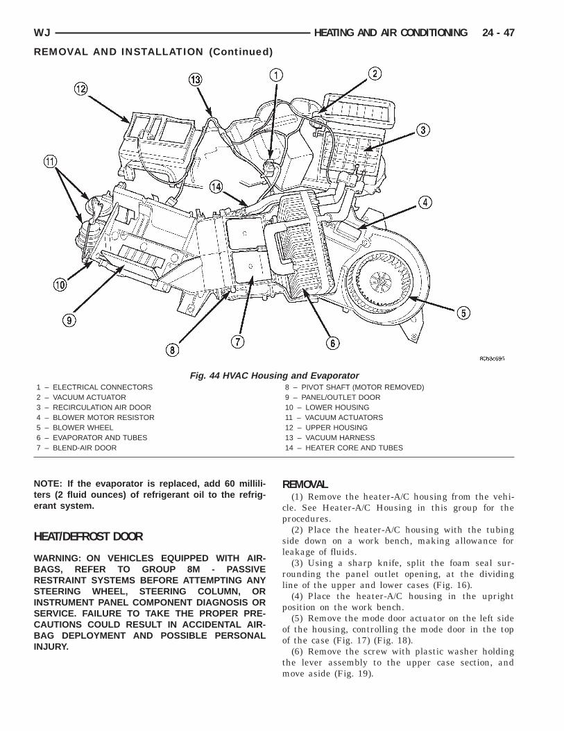
Nte
H
WBRSISCBI
WJ HEATING AND AIR CONDITIONING 24 - 47
REMOVAL AND INSTALLATION (Continued)
OTE: If the evaporator is replaced, add 60 millili-ers (2 fluid ounces) of refrigerant oil to the refrig-rant system.
EAT/DEFROST DOOR
ARNING: ON VEHICLES EQUIPPED WITH AIR-AGS, REFER TO GROUP 8M - PASSIVEESTRAINT SYSTEMS BEFORE ATTEMPTING ANYTEERING WHEEL, STEERING COLUMN, OR
NSTRUMENT PANEL COMPONENT DIAGNOSIS ORERVICE. FAILURE TO TAKE THE PROPER PRE-AUTIONS COULD RESULT IN ACCIDENTAL AIR-AG DEPLOYMENT AND POSSIBLE PERSONAL
NJURY.
Fig. 44 HVAC Hou1 – ELECTRICAL CONNECTORS2 – VACUUM ACTUATOR3 – RECIRCULATION AIR DOOR4 – BLOWER MOTOR RESISTOR5 – BLOWER WHEEL6 – EVAPORATOR AND TUBES7 – BLEND-AIR DOOR
REMOVAL(1) Remove the heater-A/C housing from the vehi-
cle. See Heater-A/C Housing in this group for theprocedures.
(2) Place the heater-A/C housing with the tubingside down on a work bench, making allowance forleakage of fluids.
(3) Using a sharp knife, split the foam seal sur-rounding the panel outlet opening, at the dividingline of the upper and lower cases (Fig. 16).
(4) Place the heater-A/C housing in the uprightposition on the work bench.
(5) Remove the mode door actuator on the left sideof the housing, controlling the mode door in the topof the case (Fig. 17) (Fig. 18).
(6) Remove the screw with plastic washer holdingthe lever assembly to the upper case section, andmove aside (Fig. 19).
and Evaporator8 – PIVOT SHAFT (MOTOR REMOVED)9 – PANEL/OUTLET DOOR10 – LOWER HOUSING11 – VACUUM ACTUATORS12 – UPPER HOUSING13 – VACUUM HARNESS14 – HEATER CORE AND TUBES
sing
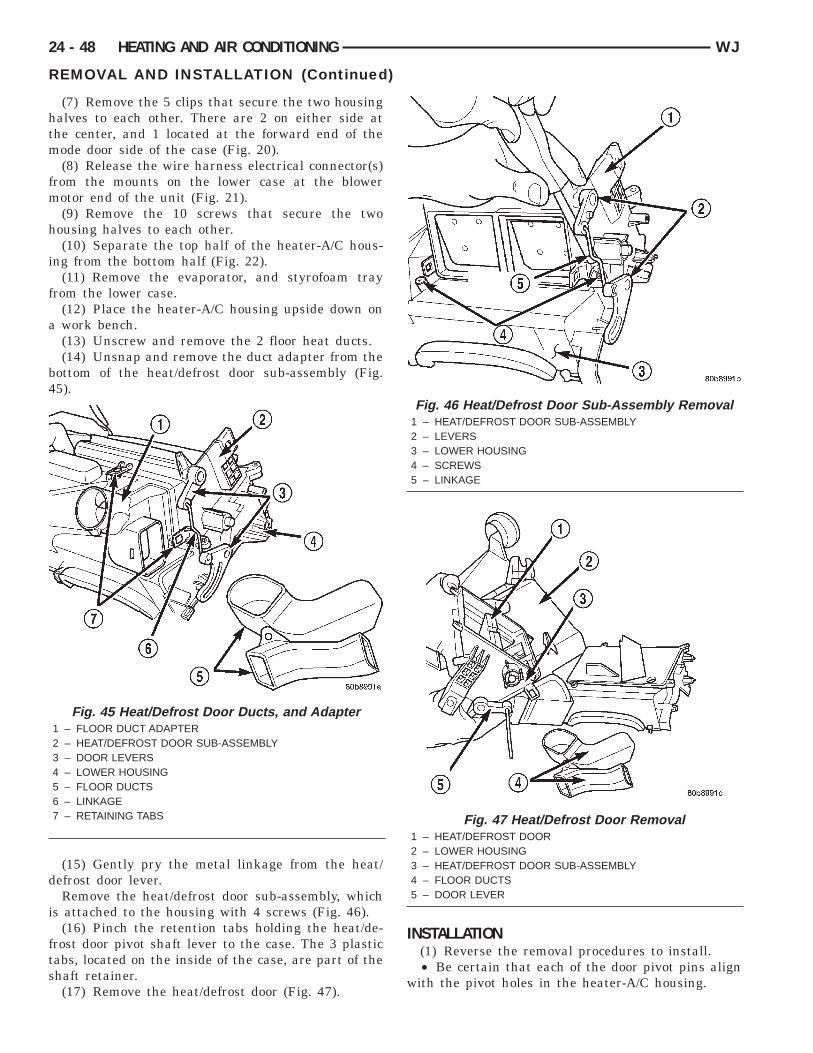
htm
fm
h
i
f
a
b4
d
i
fts
24 - 48 HEATING AND AIR CONDITIONING WJ
REMOVAL AND INSTALLATION (Continued)
(7) Remove the 5 clips that secure the two housingalves to each other. There are 2 on either side athe center, and 1 located at the forward end of theode door side of the case (Fig. 20).(8) Release the wire harness electrical connector(s)
rom the mounts on the lower case at the blowerotor end of the unit (Fig. 21).(9) Remove the 10 screws that secure the two
ousing halves to each other.(10) Separate the top half of the heater-A/C hous-
ng from the bottom half (Fig. 22).(11) Remove the evaporator, and styrofoam tray
rom the lower case.(12) Place the heater-A/C housing upside down onwork bench.(13) Unscrew and remove the 2 floor heat ducts.(14) Unsnap and remove the duct adapter from the
ottom of the heat/defrost door sub-assembly (Fig.5).
(15) Gently pry the metal linkage from the heat/efrost door lever.Remove the heat/defrost door sub-assembly, which
s attached to the housing with 4 screws (Fig. 46).(16) Pinch the retention tabs holding the heat/de-
rost door pivot shaft lever to the case. The 3 plasticabs, located on the inside of the case, are part of thehaft retainer.
Fig. 45 Heat/Defrost Door Ducts, and Adapter1 – FLOOR DUCT ADAPTER2 – HEAT/DEFROST DOOR SUB-ASSEMBLY3 – DOOR LEVERS4 – LOWER HOUSING5 – FLOOR DUCTS6 – LINKAGE7 – RETAINING TABS
(17) Remove the heat/defrost door (Fig. 47).
INSTALLATION(1) Reverse the removal procedures to install.• Be certain that each of the door pivot pins align
with the pivot holes in the heater-A/C housing.
Fig. 46 Heat/Defrost Door Sub-Assembly Removal1 – HEAT/DEFROST DOOR SUB-ASSEMBLY2 – LEVERS3 – LOWER HOUSING4 – SCREWS5 – LINKAGE
Fig. 47 Heat/Defrost Door Removal1 – HEAT/DEFROST DOOR2 – LOWER HOUSING3 – HEAT/DEFROST DOOR SUB-ASSEMBLY4 – FLOOR DUCTS5 – DOOR LEVER
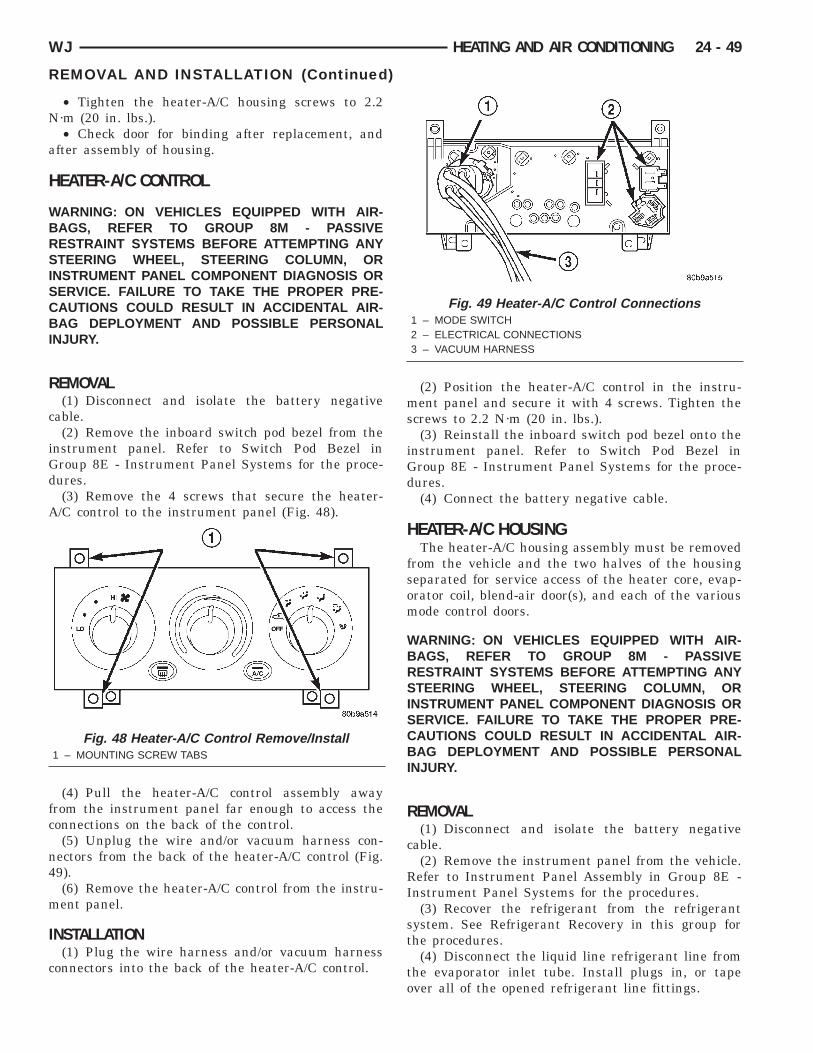
N
a
H
WBRSISCBI
R
c
iGd
A
fc
n4
m
I
c
WJ HEATING AND AIR CONDITIONING 24 - 49
REMOVAL AND INSTALLATION (Continued)
• Tighten the heater-A/C housing screws to 2.2·m (20 in. lbs.).• Check door for binding after replacement, and
fter assembly of housing.
EATER-A/C CONTROL
ARNING: ON VEHICLES EQUIPPED WITH AIR-AGS, REFER TO GROUP 8M - PASSIVEESTRAINT SYSTEMS BEFORE ATTEMPTING ANYTEERING WHEEL, STEERING COLUMN, OR
NSTRUMENT PANEL COMPONENT DIAGNOSIS ORERVICE. FAILURE TO TAKE THE PROPER PRE-AUTIONS COULD RESULT IN ACCIDENTAL AIR-AG DEPLOYMENT AND POSSIBLE PERSONAL
NJURY.
EMOVAL(1) Disconnect and isolate the battery negative
able.(2) Remove the inboard switch pod bezel from the
nstrument panel. Refer to Switch Pod Bezel inroup 8E - Instrument Panel Systems for the proce-ures.(3) Remove the 4 screws that secure the heater-/C control to the instrument panel (Fig. 48).
(4) Pull the heater-A/C control assembly awayrom the instrument panel far enough to access theonnections on the back of the control.(5) Unplug the wire and/or vacuum harness con-
ectors from the back of the heater-A/C control (Fig.9).(6) Remove the heater-A/C control from the instru-ent panel.
NSTALLATION(1) Plug the wire harness and/or vacuum harness
onnectors into the back of the heater-A/C control.
Fig. 48 Heater-A/C Control Remove/Install1 – MOUNTING SCREW TABS
(2) Position the heater-A/C control in the instru-ment panel and secure it with 4 screws. Tighten thescrews to 2.2 N·m (20 in. lbs.).
(3) Reinstall the inboard switch pod bezel onto theinstrument panel. Refer to Switch Pod Bezel inGroup 8E - Instrument Panel Systems for the proce-dures.
(4) Connect the battery negative cable.
HEATER-A/C HOUSINGThe heater-A/C housing assembly must be removed
from the vehicle and the two halves of the housingseparated for service access of the heater core, evap-orator coil, blend-air door(s), and each of the variousmode control doors.
WARNING: ON VEHICLES EQUIPPED WITH AIR-BAGS, REFER TO GROUP 8M - PASSIVERESTRAINT SYSTEMS BEFORE ATTEMPTING ANYSTEERING WHEEL, STEERING COLUMN, ORINSTRUMENT PANEL COMPONENT DIAGNOSIS ORSERVICE. FAILURE TO TAKE THE PROPER PRE-CAUTIONS COULD RESULT IN ACCIDENTAL AIR-BAG DEPLOYMENT AND POSSIBLE PERSONALINJURY.
REMOVAL(1) Disconnect and isolate the battery negative
cable.(2) Remove the instrument panel from the vehicle.
Refer to Instrument Panel Assembly in Group 8E -Instrument Panel Systems for the procedures.
(3) Recover the refrigerant from the refrigerantsystem. See Refrigerant Recovery in this group forthe procedures.
(4) Disconnect the liquid line refrigerant line fromthe evaporator inlet tube. Install plugs in, or tapeover all of the opened refrigerant line fittings.
Fig. 49 Heater-A/C Control Connections1 – MODE SWITCH2 – ELECTRICAL CONNECTIONS3 – VACUUM HARNESS
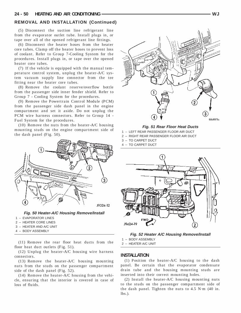
ft
coph
ptf
fG
fcPF
mt
f
c
ns
cl
24 - 50 HEATING AND AIR CONDITIONING WJ
REMOVAL AND INSTALLATION (Continued)
(5) Disconnect the suction line refrigerant linerom the evaporator outlet tube. Install plugs in, orape over all of the opened refrigerant line fittings.
(6) Disconnect the heater hoses from the heaterore tubes. Clamp off the heater hoses to prevent lossf coolant. Refer to Group 7-Cooling System for therocedures. Install plugs in, or tape over the openedeater core tubes.(7) If the vehicle is equipped with the manual tem-
erature control system, unplug the heater-A/C sys-em vacuum supply line connector from the teeitting near the heater core tubes.
(8) Remove the coolant reserve/overflow bottlerom the passenger side inner fender shield. Refer toroup 7 - Cooling System for the procedures.(9) Remove the Powertrain Control Module (PCM)
rom the passenger side dash panel in the engineompartment and set it aside. Do not unplug theCM wire harness connectors. Refer to Group 14 -uel System for the procedures.(10) Remove the nuts from the heater-A/C housingounting studs on the engine compartment side of
he dash panel (Fig. 50).
(11) Remove the rear floor heat ducts from theloor heat duct outlets (Fig. 51).
(12) Unplug the heater-A/C housing wire harnessonnectors.(13) Remove the heater-A/C housing mounting
uts from the studs on the passenger compartmentide of the dash panel (Fig. 52).(14) Remove the heater-A/C housing from the vehi-
le, ensuring that the interior is covered in case ofoss of fluids.
Fig. 50 Heater-A/C Housing Remove/Install1 – EVAPORATOR LINES2 – HEATER CORE LINES3 – HEATER AND A/C UNIT4 – BODY ASSEMBLY
INSTALLATION(1) Position the heater-A/C housing to the dash
panel. Be certain that the evaporator condensatedrain tube and the housing mounting studs areinserted into their correct mounting holes.
(2) Install the heater-A/C housing mounting nutsto the studs on the passenger compartment side ofthe dash panel. Tighten the nuts to 4.5 N·m (40 in.lbs.).
Fig. 51 Rear Floor Heat Ducts1 – LEFT REAR PASSENGER FLOOR AIR DUCT2 – RIGHT REAR PASSENGER FLOOR AIR DUCT3 – TO CARPET DUCT4 – TO CARPET DUCT
Fig. 52 Heater A/C Housing Remove/Install1 – BODY ASSEMBLY2 – HEATER A/C UNIT
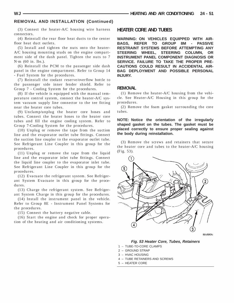
c
f
AmN
p-
tG
ptn
ttG
ltSp
ltSp
ad
a
Rt
t
WJ HEATING AND AIR CONDITIONING 24 - 51
REMOVAL AND INSTALLATION (Continued)
(3) Connect the heater-A/C housing wire harnessonnectors.(4) Reinstall the rear floor heat ducts to the center
loor heat duct outlets.(5) Install and tighten the nuts onto the heater-/C housing mounting studs on the engine compart-ent side of the dash panel. Tighten the nuts to 7·m (60 in. lbs.).(6) Reinstall the PCM to the passenger side dash
anel in the engine compartment. Refer to Group 14Fuel System for the procedures.(7) Reinstall the coolant reserve/overflow bottle to
he passenger side inner fender shield. Refer toroup 7 - Cooling System for the procedures.(8) If the vehicle is equipped with the manual tem-
erature control system, connect the heater-A/C sys-em vacuum supply line connector to the tee fittingear the heater core tubes.(9) Unclamp/unplug the heater core hoses and
ubes. Connect the heater hoses to the heater coreubes and fill the engine cooling system. Refer toroup 7-Cooling System for the procedures.(10) Unplug or remove the tape from the suction
ine and the evaporator outlet tube fittings. Connecthe suction line coupler to the evaporator outlet tube.ee Refrigerant Line Coupler in this group for therocedures.(11) Unplug or remove the tape from the liquid
ine and the evaporator inlet tube fittings. Connecthe liquid line coupler to the evaporator inlet tube.ee Refrigerant Line Coupler in this group for therocedures.(12) Evacuate the refrigerant system. See Refriger-
nt System Evacuate in this group for the proce-ures.(13) Charge the refrigerant system. See Refriger-
nt System Charge in this group for the procedures.(14) Install the instrument panel in the vehicle.efer to Group 8E - Instrument Panel Systems for
he procedures.(15) Connect the battery negative cable.(16) Start the engine and check for proper opera-
ion of the heating and air conditioning systems.
HEATER CORE AND TUBES
WARNING: ON VEHICLES EQUIPPED WITH AIR-BAGS, REFER TO GROUP 8M - PASSIVERESTRAINT SYSTEMS BEFORE ATTEMPTING ANYSTEERING WHEEL, STEERING COLUMN, ORINSTRUMENT PANEL COMPONENT DIAGNOSIS ORSERVICE. FAILURE TO TAKE THE PROPER PRE-CAUTIONS COULD RESULT IN ACCIDENTAL AIR-BAG DEPLOYMENT AND POSSIBLE PERSONALINJURY.
REMOVAL(1) Remove the heater-A/C housing from the vehi-
cle. See Heater-A/C Housing in this group for theprocedures.
(2) Remove the foam gasket surrounding the coretubes.
NOTE: Notice the orientation of the irregularlyshaped gasket on the tubes. The gasket must beplaced correctly to ensure proper sealing againstthe body during reinstallation.
(3) Remove the screws and retainers that securethe heater core and tubes to the heater-A/C housing(Fig. 53).
Fig. 53 Heater Core, Tubes, Retainers1 – TUBE-TO-CORE CLAMPS2 – GROUND STRAP3 – HVAC HOUSING4 – TUBE RETAINERS AND SCREWS5 – HEATER CORE

f
h
rf
I
iai
NbPtt
h
h
24 - 52 HEATING AND AIR CONDITIONING WJ
REMOVAL AND INSTALLATION (Continued)
(4) Remove the mode door actuator if necessary,or clearance to remove the core.
(5) Lift the heater core straight up and out of theeater-A/C housing (Fig. 54).(6) When replacing individual tubes, loosen and
emove the round tube-to-core clamp, and pull tuberom core.
NSTALLATION(1) When installing individual tubes, insert tube
nto core ensuring that tube O-ring is seated in corend not pinched. Hold tube in seated position whilenstalling the round tube-to-core clamp (Fig. 55).
OTE: The round tube-to-heater-core clamp shoulde left loose enough to turn the tube in the core.osition the core in the housing, and then tighten
he tube-to-heater-core clamp after orienting theubes to the molded heater-A/C housing.
(2) Lower the heater core into the heater-A/Cousing.(3) Install the mode door actuator, if removed from
ousing for core removal.
Fig. 54 Heater1 – ELECTRICAL CONNECTORS2 – EVAPORATOR FITTINGS (CAPPED)3 – ELECTRIC ACTUATOR4 – OUTLET TO DEFROSTER DUCTS5 – ELECTRIC ACTUATOR6 – FLOOR DUCT7 – TO REAR PASSENGER FLOOR AIR DUCTS
(4) Position the retainers over the heater coretubes. Install and tighten the screws that secure theheater core and retainers to the heater-A/C housing.Tighten the screws to 2.2 N·m (20 in. lbs.).
NOTE: The grounding strap is to be attached to thelower heater core tube retainer.
(5) Reinstall the heater-A/C housing to the vehicle.See Heater-A/C Housing in this group for the proce-dures.
HIGH PRESSURE RELIEF VALVE
WARNING: REVIEW THE WARNINGS AND CAU-TIONS IN THE FRONT OF THIS GROUP BEFOREPERFORMING THE FOLLOWING OPERATION.
REMOVAL(1) Disconnect and isolate the battery negative
cable.(2) Recover the refrigerant from the refrigerant
system. See Refrigerant Recovery in this group forthe procedures.
e and Tubes8 – FLOOR DUCT9 – HEATER CORE AND TUBES10 – HOUSING DRAIN11 – BLOWER MOTOR CONTROLLER/POWER MODULE12 – BLOWER MOTOR13 – GROUND STRAP
Cor
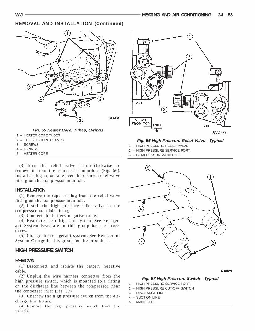
rIf
I
f
c
ad
S
H
R
c
hot
c
v
WJ HEATING AND AIR CONDITIONING 24 - 53
REMOVAL AND INSTALLATION (Continued)
(3) Turn the relief valve counterclockwise toemove it from the compressor manifold (Fig. 56).nstall a plug in, or tape over the opened relief valveitting on the compressor manifold.
NSTALLATION(1) Remove the tape or plug from the relief valve
itting on the compressor manifold.(2) Install the high pressure relief valve in the
ompressor manifold fitting.(3) Connect the battery negative cable.(4) Evacuate the refrigerant system. See Refriger-
nt System Evacuate in this group for the proce-ures.(5) Charge the refrigerant system. See Refrigerant
ystem Charge in this group for the procedures.
IGH PRESSURE SWITCH
EMOVAL(1) Disconnect and isolate the battery negative
able.(2) Unplug the wire harness connector from the
igh pressure switch, which is mounted to a fittingn the discharge line between the compressor, nearhe condenser inlet (Fig. 57).
(3) Unscrew the high pressure switch from the dis-harge line fitting.(4) Remove the high pressure switch from the
ehicle.
Fig. 55 Heater Core, Tubes, O-rings1 – HEATER CORE TUBES2 – TUBE-TO-CORE CLAMPS3 – SCREWS4 – O-RINGS5 – HEATER CORE
Fig. 56 High Pressure Relief Valve - Typical1 – HIGH PRESSURE RELIEF VALVE2 – HIGH PRESSURE SERVICE PORT3 – COMPRESSOR MANIFOLD
Fig. 57 High Pressure Switch - Typical1 – HIGH PRESSURE SERVICE PORT2 – HIGH PRESSURE CUT-OFF SWITCH3 – DISCHARGE LINE4 – SUCTION LINE5 – MANIFOLD
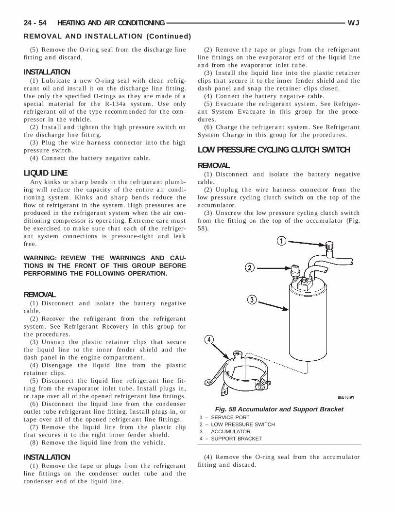
f
I
eUsrp
t
p
L
itfpdbaf
WTP
R
c
st
td
r
to
ot
t
I
lc
24 - 54 HEATING AND AIR CONDITIONING WJ
REMOVAL AND INSTALLATION (Continued)
(5) Remove the O-ring seal from the discharge lineitting and discard.
NSTALLATION(1) Lubricate a new O-ring seal with clean refrig-
rant oil and install it on the discharge line fitting.se only the specified O-rings as they are made of a
pecial material for the R-134a system. Use onlyefrigerant oil of the type recommended for the com-ressor in the vehicle.(2) Install and tighten the high pressure switch on
he discharge line fitting.(3) Plug the wire harness connector into the high
ressure switch.(4) Connect the battery negative cable.
IQUID LINEAny kinks or sharp bends in the refrigerant plumb-
ng will reduce the capacity of the entire air condi-ioning system. Kinks and sharp bends reduce thelow of refrigerant in the system. High pressures areroduced in the refrigerant system when the air con-itioning compressor is operating. Extreme care muste exercised to make sure that each of the refriger-nt system connections is pressure-tight and leakree.
ARNING: REVIEW THE WARNINGS AND CAU-IONS IN THE FRONT OF THIS GROUP BEFOREERFORMING THE FOLLOWING OPERATION.
EMOVAL(1) Disconnect and isolate the battery negative
able.(2) Recover the refrigerant from the refrigerant
ystem. See Refrigerant Recovery in this group forhe procedures.
(3) Unsnap the plastic retainer clips that securehe liquid line to the inner fender shield and theash panel in the engine compartment.(4) Disengage the liquid line from the plastic
etainer clips.(5) Disconnect the liquid line refrigerant line fit-
ing from the evaporator inlet tube. Install plugs in,r tape over all of the opened refrigerant line fittings.(6) Disconnect the liquid line from the condenser
utlet tube refrigerant line fitting. Install plugs in, orape over all of the opened refrigerant line fittings.
(7) Remove the liquid line from the plastic cliphat secures it to the right inner fender shield.
(8) Remove the liquid line from the vehicle.
NSTALLATION(1) Remove the tape or plugs from the refrigerant
ine fittings on the condenser outlet tube and theondenser end of the liquid line.
(2) Remove the tape or plugs from the refrigerantline fittings on the evaporator end of the liquid lineand from the evaporator inlet tube.
(3) Install the liquid line into the plastic retainerclips that secure it to the inner fender shield and thedash panel and snap the retainer clips closed.
(4) Connect the battery negative cable.(5) Evacuate the refrigerant system. See Refriger-
ant System Evacuate in this group for the proce-dures.
(6) Charge the refrigerant system. See RefrigerantSystem Charge in this group for the procedures.
LOW PRESSURE CYCLING CLUTCH SWITCH
REMOVAL(1) Disconnect and isolate the battery negative
cable.(2) Unplug the wire harness connector from the
low pressure cycling clutch switch on the top of theaccumulator.
(3) Unscrew the low pressure cycling clutch switchfrom the fitting on the top of the accumulator (Fig.58).
(4) Remove the O-ring seal from the accumulatorfitting and discard.
Fig. 58 Accumulator and Support Bracket1 – SERVICE PORT2 – LOW PRESSURE SWITCH3 – ACCUMULATOR4 – SUPPORT BRACKET
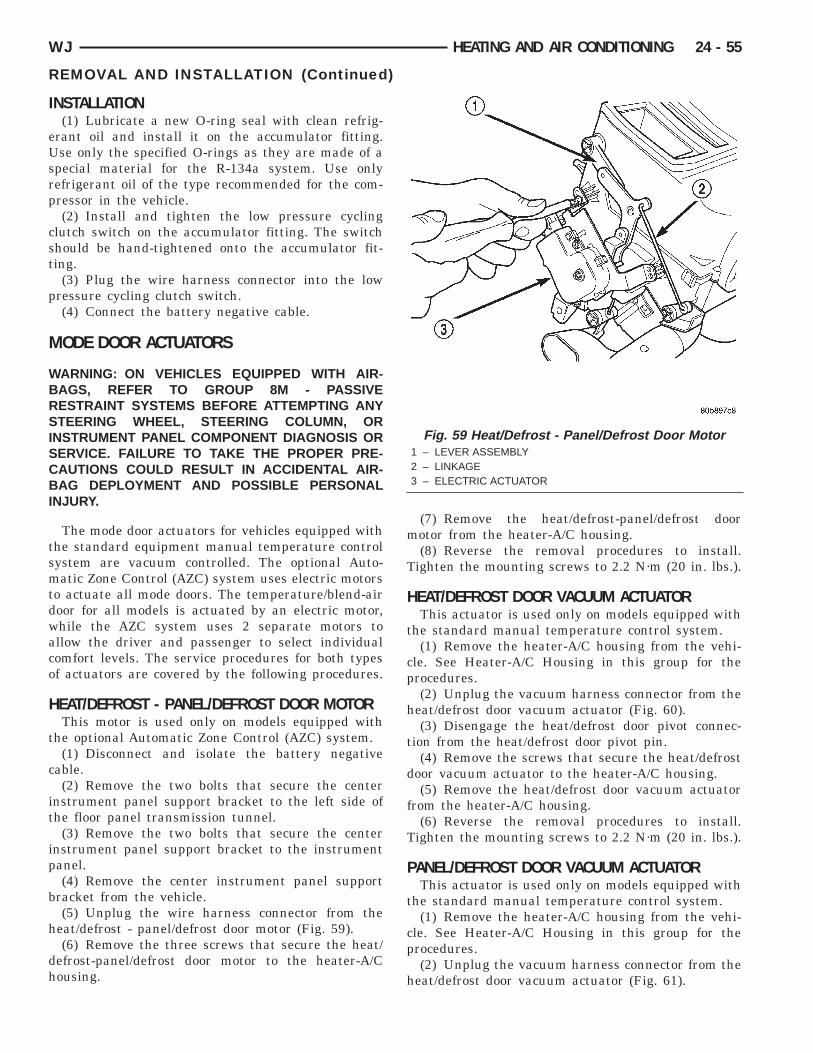
I
eUsrp
cst
p
M
WBRSISCBI
tsmtdwaco
H
t
c
it
ip
b
h
dh
WJ HEATING AND AIR CONDITIONING 24 - 55
REMOVAL AND INSTALLATION (Continued)
NSTALLATION(1) Lubricate a new O-ring seal with clean refrig-
rant oil and install it on the accumulator fitting.se only the specified O-rings as they are made of a
pecial material for the R-134a system. Use onlyefrigerant oil of the type recommended for the com-ressor in the vehicle.(2) Install and tighten the low pressure cycling
lutch switch on the accumulator fitting. The switchhould be hand-tightened onto the accumulator fit-ing.
(3) Plug the wire harness connector into the lowressure cycling clutch switch.(4) Connect the battery negative cable.
ODE DOOR ACTUATORS
ARNING: ON VEHICLES EQUIPPED WITH AIR-AGS, REFER TO GROUP 8M - PASSIVEESTRAINT SYSTEMS BEFORE ATTEMPTING ANYTEERING WHEEL, STEERING COLUMN, OR
NSTRUMENT PANEL COMPONENT DIAGNOSIS ORERVICE. FAILURE TO TAKE THE PROPER PRE-AUTIONS COULD RESULT IN ACCIDENTAL AIR-AG DEPLOYMENT AND POSSIBLE PERSONAL
NJURY.
The mode door actuators for vehicles equipped withhe standard equipment manual temperature controlystem are vacuum controlled. The optional Auto-atic Zone Control (AZC) system uses electric motors
o actuate all mode doors. The temperature/blend-airoor for all models is actuated by an electric motor,hile the AZC system uses 2 separate motors tollow the driver and passenger to select individualomfort levels. The service procedures for both typesf actuators are covered by the following procedures.
EAT/DEFROST - PANEL/DEFROST DOOR MOTORThis motor is used only on models equipped with
he optional Automatic Zone Control (AZC) system.(1) Disconnect and isolate the battery negative
able.(2) Remove the two bolts that secure the center
nstrument panel support bracket to the left side ofhe floor panel transmission tunnel.
(3) Remove the two bolts that secure the centernstrument panel support bracket to the instrumentanel.(4) Remove the center instrument panel support
racket from the vehicle.(5) Unplug the wire harness connector from the
eat/defrost - panel/defrost door motor (Fig. 59).(6) Remove the three screws that secure the heat/
efrost-panel/defrost door motor to the heater-A/Cousing.
(7) Remove the heat/defrost-panel/defrost doormotor from the heater-A/C housing.
(8) Reverse the removal procedures to install.Tighten the mounting screws to 2.2 N·m (20 in. lbs.).
HEAT/DEFROST DOOR VACUUM ACTUATORThis actuator is used only on models equipped with
the standard manual temperature control system.(1) Remove the heater-A/C housing from the vehi-
cle. See Heater-A/C Housing in this group for theprocedures.
(2) Unplug the vacuum harness connector from theheat/defrost door vacuum actuator (Fig. 60).
(3) Disengage the heat/defrost door pivot connec-tion from the heat/defrost door pivot pin.
(4) Remove the screws that secure the heat/defrostdoor vacuum actuator to the heater-A/C housing.
(5) Remove the heat/defrost door vacuum actuatorfrom the heater-A/C housing.
(6) Reverse the removal procedures to install.Tighten the mounting screws to 2.2 N·m (20 in. lbs.).
PANEL/DEFROST DOOR VACUUM ACTUATORThis actuator is used only on models equipped with
the standard manual temperature control system.(1) Remove the heater-A/C housing from the vehi-
cle. See Heater-A/C Housing in this group for theprocedures.
(2) Unplug the vacuum harness connector from theheat/defrost door vacuum actuator (Fig. 61).
Fig. 59 Heat/Defrost - Panel/Defrost Door Motor1 – LEVER ASSEMBLY2 – LINKAGE3 – ELECTRIC ACTUATOR
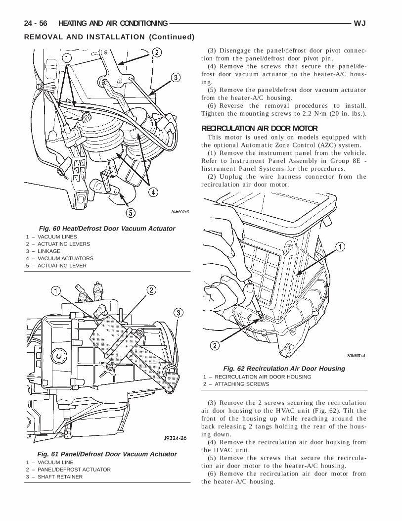
24 - 56 HEATING AND AIR CONDITIONING WJ
REMOVAL AND INSTALLATION (Continued)
(3) Disengage the panel/defrost door pivot connec-tion from the panel/defrost door pivot pin.
(4) Remove the screws that secure the panel/de-frost door vacuum actuator to the heater-A/C hous-ing.
(5) Remove the panel/defrost door vacuum actuatorfrom the heater-A/C housing.
(6) Reverse the removal procedures to install.Tighten the mounting screws to 2.2 N·m (20 in. lbs.).
RECIRCULATION AIR DOOR MOTORThis motor is used only on models equipped with
the optional Automatic Zone Control (AZC) system.(1) Remove the instrument panel from the vehicle.
Refer to Instrument Panel Assembly in Group 8E -Instrument Panel Systems for the procedures.
(2) Unplug the wire harness connector from therecirculation air door motor.
(3) Remove the 2 screws securing the recirculationair door housing to the HVAC unit (Fig. 62). Tilt thefront of the housing up while reaching around theback releasing 2 tangs holding the rear of the hous-ing down.
(4) Remove the recirculation air door housing fromthe HVAC unit.
(5) Remove the screws that secure the recircula-tion air door motor to the heater-A/C housing.
(6) Remove the recirculation air door motor fromthe heater-A/C housing.
Fig. 62 Recirculation Air Door Housing1 – RECIRCULATION AIR DOOR HOUSING2 – ATTACHING SCREWS
Fig. 60 Heat/Defrost Door Vacuum Actuator1 – VACUUM LINES2 – ACTUATING LEVERS3 – LINKAGE4 – VACUUM ACTUATORS5 – ACTUATING LEVER
Fig. 61 Panel/Defrost Door Vacuum Actuator1 – VACUUM LINE2 – PANEL/DEFROST ACTUATOR3 – SHAFT RETAINER
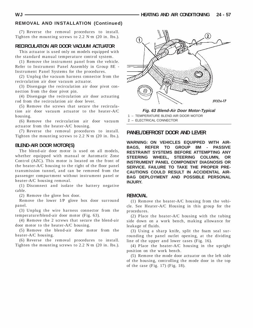
T
R
t
RI
r
n
r
th
a
T
B
wCttph
c
p
t
d
h
T
WJ HEATING AND AIR CONDITIONING 24 - 57
REMOVAL AND INSTALLATION (Continued)
(7) Reverse the removal procedures to install.ighten the mounting screws to 2.2 N·m (20 in. lbs.).
ECIRCULATION AIR DOOR VACUUM ACTUATORThis actuator is used only on models equipped with
he standard manual temperature control system.(1) Remove the instrument panel from the vehicle.efer to Instrument Panel Assembly in Group 8E -
nstrument Panel Systems for the procedures.(2) Unplug the vacuum harness connector from the
ecirculation air door vacuum actuator.(3) Disengage the recirculation air door pivot con-
ection from the door pivot pin.(4) Disengage the recirculation air door actuating
od from the recirculation air door lever.(5) Remove the screws that secure the recircula-
ion air door vacuum actuator to the heater-A/Cousing.(6) Remove the recirculation air door vacuum
ctuator from the heater-A/C housing.(7) Reverse the removal procedures to install.
ighten the mounting screws to 2.2 N·m (20 in. lbs.).
LEND-AIR DOOR MOTOR(S)The blend-air door motor is used on all models,hether equipped with manual or Automatic Zoneontrol (AZC). This motor is located on the front of
he heater-A/C housing to the right of the floor panelransmission tunnel, and can be removed from theassenger compartment without instrument panel oreater-A/C housing removal.(1) Disconnect and isolate the battery negative
able.(2) Remove the glove box door.Remove the lower I/P glove box door surround
anel.(3) Unplug the wire harness connector from the
emperature/blend-air door motor (Fig. 63).(4) Remove the 2 screws that secure the blend-air
oor motor to the heater-A/C housing.(5) Remove the blend-air door motor from the
eater-A/C housing.(6) Reverse the removal procedures to install.
ighten the mounting screws to 2.2 N·m (20 in. lbs.).
PANEL/DEFROST DOOR AND LEVER
WARNING: ON VEHICLES EQUIPPED WITH AIR-BAGS, REFER TO GROUP 8M - PASSIVERESTRAINT SYSTEMS BEFORE ATTEMPTING ANYSTEERING WHEEL, STEERING COLUMN, ORINSTRUMENT PANEL COMPONENT DIAGNOSIS ORSERVICE. FAILURE TO TAKE THE PROPER PRE-CAUTIONS COULD RESULT IN ACCIDENTAL AIR-BAG DEPLOYMENT AND POSSIBLE PERSONALINJURY.
REMOVAL(1) Remove the heater-A/C housing from the vehi-
cle. See Heater-A/C Housing in this group for theprocedures.
(2) Place the heater-A/C housing with the tubingside down on a work bench, making allowance forleakage of fluids.
(3) Using a sharp knife, split the foam seal sur-rounding the panel outlet opening, at the dividingline of the upper and lower cases (Fig. 16).
(4) Place the heater-A/C housing in the uprightposition on the work bench.
(5) Remove the mode door actuator on the left sideof the housing, controlling the mode door in the topof the case (Fig. 17) (Fig. 18).
Fig. 63 Blend-Air Door Motor-Typical1 – TEMPERATURE BLEND AIR DOOR MOTOR2 – ELECTRICAL CONNECTOR
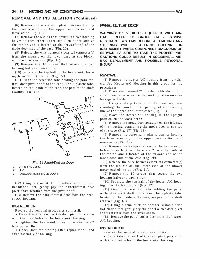
tm
htm
fm
h
i
flr
fp
e
I
w
N
a
24 - 58 HEATING AND AIR CONDITIONING WJ
REMOVAL AND INSTALLATION (Continued)
(6) Remove the screw with plastic washer holdinghe lever assembly to the upper case section, andove aside (Fig. 19).(7) Remove the 5 clips that secure the two housing
alves to each other. There are 2 on either side athe center, and 1 located at the forward end of theode door side of the case (Fig. 20).(8) Release the wire harness electrical connector(s)
rom the mounts on the lower case at the blowerotor end of the unit (Fig. 21).(9) Remove the 10 screws that secure the two
ousing halves to each other.(10) Separate the top half of the heater-A/C hous-
ng from the bottom half (Fig. 22).(11) Pinch the retention tabs holding the panel/de-
rost door pivot shaft to the case. The 3 plastic tabs,ocated on the inside of the case, are part of the shaftetainer (Fig. 64).
(12) Using a trim stick or another suitable widelat-bladed tool, gently pry the panel/defrost doorivot shaft retainer from the pivot shaft.(13) Remove the panel/defrost door from the heat-
r-A/C housing.
NSTALLATIONReverse the removal procedures to install.• Be certain that each of the door pivot pins alignith the pivot holes in the heater-A/C housing.• Tighten the heater-A/C housing screws to 2.2·m (20 in. lbs.).• Check door for binding after replacement, and
fter assembly of housing.
Fig. 64 Panel/Defrost Door1 – UPPER HOUSING2 – LEVER3 – PANEL/DEFROST MODE DOOR
PANEL OUTLET DOOR
WARNING: ON VEHICLES EQUIPPED WITH AIR-BAGS, REFER TO GROUP 8M - PASSIVERESTRAINT SYSTEMS BEFORE ATTEMPTING ANYSTEERING WHEEL, STEERING COLUMN, ORINSTRUMENT PANEL COMPONENT DIAGNOSIS ORSERVICE. FAILURE TO TAKE THE PROPER PRE-CAUTIONS COULD RESULT IN ACCIDENTAL AIR-BAG DEPLOYMENT AND POSSIBLE PERSONALINJURY.
REMOVAL(1) Remove the heater-A/C housing from the vehi-
cle. See Heater-A/C Housing in this group for theprocedures.
(2) Place the heater-A/C housing with the tubingside down on a work bench, making allowance forleakage of fluids.
(3) Using a sharp knife, split the foam seal sur-rounding the panel outlet opening, at the dividingline of the upper and lower cases (Fig. 16).
(4) Place the heater-A/C housing in the uprightposition on the work bench.
(5) Remove the mode door actuator on the left sideof the housing, controlling the mode door in the topof the case (Fig. 17) (Fig. 18).
(6) Remove the screw with plastic washer holdingthe lever assembly to the upper case section, andmove aside (Fig. 19).
(7) Remove the 5 clips that secure the two housinghalves to each other. There are 2 on either side atthe center, and 1 located at the forward end of themode door side of the case (Fig. 20).
(8) Release the wire harness electrical connector(s)from the mounts on the lower case at the blowermotor end of the unit (Fig. 21).
(9) Remove the 10 screws that secure the twohousing halves to each other.
(10) Separate the top half of the heater-A/C hous-ing from the bottom half (Fig. 22).
(11) Pinch the retention tabs holding the paneloutlet door pivot shaft to the case. The 3 plastic tabs,located on the inside of the case, are part of the shaftretainer (Fig. 65).
(12) Using a trim stick or another suitable wideflat-bladed tool, gently pry the panel outlet door pivotshaft retainer from the pivot shaft.
(13) Remove the panel outlet door from the heater-A/C housing.
INSTALLATIONReverse the removal procedures to install.• Be certain that each of the door pivot pins align
with the pivot holes in the heater-A/C housing.
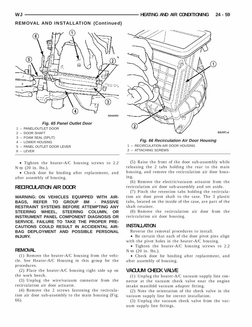
N
a
R
WBRSISCBI
R
cp
t
r
t6
WJ HEATING AND AIR CONDITIONING 24 - 59
REMOVAL AND INSTALLATION (Continued)
• Tighten the heater-A/C housing screws to 2.2·m (20 in. lbs.).• Check door for binding after replacement, and
fter assembly of housing.
ECIRCULATION AIR DOOR
ARNING: ON VEHICLES EQUIPPED WITH AIR-AGS, REFER TO GROUP 8M - PASSIVEESTRAINT SYSTEMS BEFORE ATTEMPTING ANYTEERING WHEEL, STEERING COLUMN, OR
NSTRUMENT PANEL COMPONENT DIAGNOSIS ORERVICE. FAILURE TO TAKE THE PROPER PRE-AUTIONS COULD RESULT IN ACCIDENTAL AIR-AG DEPLOYMENT AND POSSIBLE PERSONAL
NJURY.
EMOVAL(1) Remove the heater-A/C housing from the vehi-
le. See Heater-A/C Housing in this group for therocedures.(2) Place the heater-A/C housing right side up on
he work bench.(3) Unplug the wire/vacuum connector from the
ecirculation air door actuator.(4) Remove the 2 screws fastening the recircula-
ion air door sub-assembly to the main housing (Fig.6).
Fig. 65 Panel Outlet Door1 – PANEL/OUTLET DOOR2 – DOOR SHAFT3 – FOAM SEAL (SPLIT)4 – LOWER HOUSING5 – PANEL OUTLET DOOR LEVER6 – LEVER
(5) Raise the front of the door sub-assembly whilereleasing the 2 tabs holding the rear to the mainhousing, and remove the recirculation air door hous-ing.
(6) Remove the electric/vacuum actuator from therecirculation air door sub-assembly and set aside.
(7) Pinch the retention tabs holding the recircula-tion air door pivot shaft to the case. The 3 plastictabs, located on the inside of the case, are part of theshaft retainer.
(8) Remove the recirculation air door from therecirculation air door housing.
INSTALLATIONReverse the removal procedures to install.• Be certain that each of the door pivot pins align
with the pivot holes in the heater-A/C housing.• Tighten the heater-A/C housing screws to 2.2
N·m (20 in. lbs.).• Check door for binding after replacement, and
after assembly of housing.
VACUUM CHECK VALVE(1) Unplug the heater-A/C vacuum supply line con-
nector at the vacuum check valve near the engineintake manifold vacuum adapter fitting.
(2) Note the orientation of the check valve in thevacuum supply line for correct installation.
(3) Unplug the vacuum check valve from the vac-uum supply line fittings.
Fig. 66 Recirculation Air Door Housing1 – RECIRCULATION AIR DOOR HOUSING2 – ATTACHING SCREWS
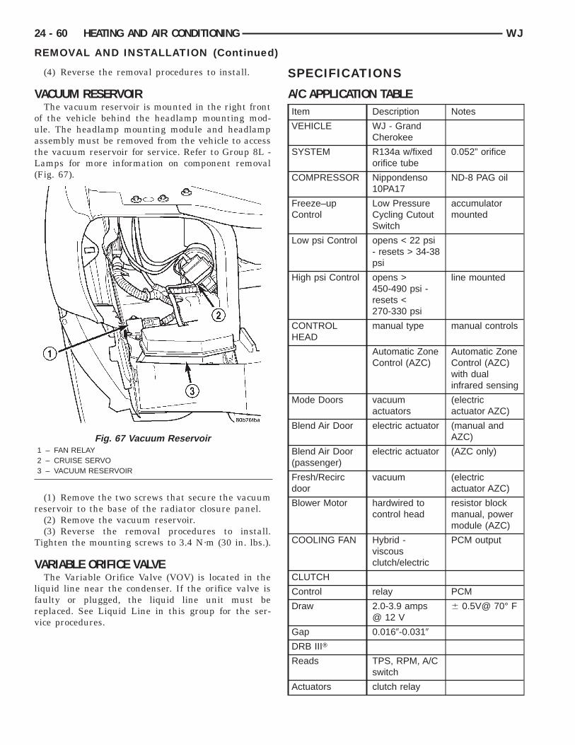
V
ouatL(
r
T
V
lfrv
24 - 60 HEATING AND AIR CONDITIONING WJ
REMOVAL AND INSTALLATION (Continued)
(4) Reverse the removal procedures to install.
ACUUM RESERVOIRThe vacuum reservoir is mounted in the right front
f the vehicle behind the headlamp mounting mod-le. The headlamp mounting module and headlampssembly must be removed from the vehicle to accesshe vacuum reservoir for service. Refer to Group 8L -amps for more information on component removal
Fig. 67).
(1) Remove the two screws that secure the vacuumeservoir to the base of the radiator closure panel.(2) Remove the vacuum reservoir.(3) Reverse the removal procedures to install.
ighten the mounting screws to 3.4 N·m (30 in. lbs.).
ARIABLE ORIFICE VALVEThe Variable Orifice Valve (VOV) is located in the
iquid line near the condenser. If the orifice valve isaulty or plugged, the liquid line unit must beeplaced. See Liquid Line in this group for the ser-ice procedures.
Fig. 67 Vacuum Reservoir1 – FAN RELAY2 – CRUISE SERVO3 – VACUUM RESERVOIR
SPECIFICATIONS
A/C APPLICATION TABLEItem Description Notes
VEHICLE WJ - GrandCherokee
SYSTEM R134a w/fixedorifice tube
0.052” orifice
COMPRESSOR Nippondenso10PA17
ND-8 PAG oil
Freeze–upControl
Low PressureCycling CutoutSwitch
accumulatormounted
Low psi Control opens < 22 psi- resets > 34-38psi
High psi Control opens >450-490 psi -resets <270-330 psi
line mounted
CONTROLHEAD
manual type manual controls
Automatic ZoneControl (AZC)
Automatic ZoneControl (AZC)with dualinfrared sensing
Mode Doors vacuumactuators
(electricactuator AZC)
Blend Air Door electric actuator (manual andAZC)
Blend Air Door(passenger)
electric actuator (AZC only)
Fresh/Recircdoor
vacuum (electricactuator AZC)
Blower Motor hardwired tocontrol head
resistor blockmanual, powermodule (AZC)
COOLING FAN Hybrid -viscousclutch/electric
PCM output
CLUTCH
Control relay PCM
Draw 2.0-3.9 amps@ 12 V
6 0.5V@ 70° F
Gap 0.0169-0.0319
DRB IIIT
Reads TPS, RPM, A/Cswitch
Actuators clutch relay