heathkit of the month #32: by bob eckweiler, af6c of the month #32: by bob eckweiler, af6c the...
TRANSCRIPT
Heathkit of the Month #32:by Bob Eckweiler, AF6C
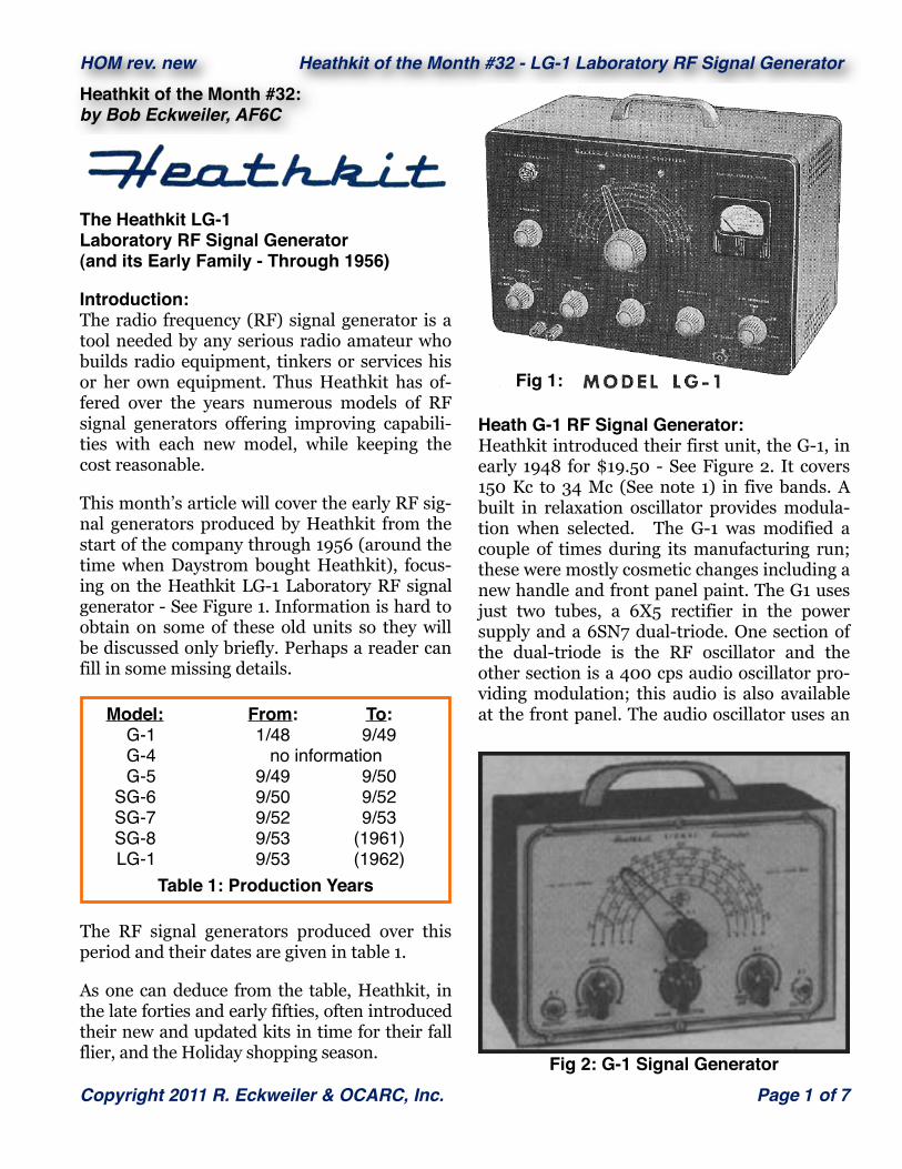
The Heathkit LG-1Laboratory RF Signal Generator(and its Early Family - Through 1956)
Introduction:The radio frequency (RF) signal generator is a tool needed by any serious radio amateur who builds radio equipment, tinkers or services his or her own equipment. Thus Heathkit has of-fered over the years numerous models of RF signal generators offering improving capabili-ties with each new model, while keeping the cost reasonable.
This month’s article will cover the early RF sig-nal generators produced by Heathkit from the start of the company through 1956 (around the time when Daystrom bought Heathkit), focus-ing on the Heathkit LG-1 Laboratory RF signal generator - See Figure 1. Information is hard to obtain on some of these old units so they will be discussed only briefly. Perhaps a reader can fill in some missing details.
The RF signal generators produced over this period and their dates are given in table 1.
As one can deduce from the table, Heathkit, in the late forties and early fifties, often introduced their new and updated kits in time for their fall flier, and the Holiday shopping season.
Model: From: To: G-1 1/48 9/49 G-4 no information G-5 9/49 9/50 SG-6 9/50 9/52 SG-7 9/52 9/53 SG-8 9/53 (1961) LG-1 9/53 (1962)
Table 1: Production Years
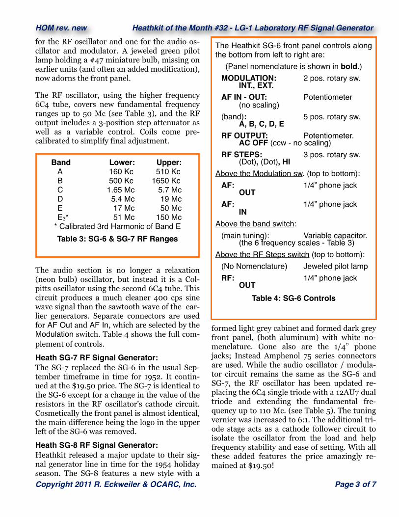
Heath G-1 RF Signal Generator:Heathkit introduced their first unit, the G-1, in early 1948 for $19.50 - See Figure 2. It covers 150 Kc to 34 Mc (See note 1) in five bands. A built in relaxation oscillator provides modula-tion when selected. The G-1 was modified a couple of times during its manufacturing run; these were mostly cosmetic changes including a new handle and front panel paint. The G1 uses just two tubes, a 6X5 rectifier in the power supply and a 6SN7 dual-triode. One section of the dual-triode is the RF oscillator and the other section is a 400 cps audio oscillator pro-viding modulation; this audio is also available at the front panel. The audio oscillator uses an
HOM rev. new Heathkit of the Month #32 - LG-1 Laboratory RF Signal Generator
Copyright 2011 R. Eckweiler & OCARC, Inc. Page 1 of 7Fig 2: G-1 Signal Generator
Fig 1:

NE-51 neon bulb in a relaxation type circuit. Front panel controls are simple. A 5-band switch (see table-two for the frequency ranges), a tuning control with a plastic graticule over a front panel 5-band scale, an RF level control with power switch, an audio level control with modulation switch, and 1/4” phone jacks for RF and audio output. The G-1 tuning knob is direct drive so adjustment is a bit challenging.
Heath G-4 HF-AM Signal Generator:Here is a mystery kit. I found some references to this kit, but no schematic or description other than the title. I even found one place sell-ing a photo copy of the manual, which I’d buy if I actually had the unit. Heathkit made a G-2 Audio Oscillator and a G-3 Sweep Generator, so the existence of a G-4 is a given.
Band Lower: Upper: A 150 Kc 450 Kc B 450 Kc 1300 Kc C 1.3 Mc 4.0 Mc D 4 Mc 12 Mc E 12 Mc 34 Mc E3* 34 Mc 102 Mc
(* G-5 only)Table 2: G-1 & G5 Band Ranges
Heath G-5 RF Signal Generator:Electrically, the G-5 is similar to the G-1 with just a few component refinements. It features 5:1 vernier tuning and a new scale that now in-cludes the third harmonic of band E (36 Mc to 102 Mc). The G-5’s audio circuit was altered to allow external modulation, making the audio-out phone jack also the audio-in connector. The AF IN - OUT control is marked INT. MOD. at its fully counterclockwise position and EXT. MOD. at its fully clockwise position. When turned fully CCW the switch controlling modulation type is switched to the internal position, where it remains until the control is moved fully CW where it switches to the external position. There it remains until again moved fully CCW. Thus the control acts as both audio output level, audio input level and audio in / out selector.
Heath SG-6 RF Signal Generator:In time for the 1951 updates, Heathkit changed their nomenclature; the G line became the more distinguishable SG line. Heath entered this dec-ade with the SG-6 signal generator (Figure 3) that still sold for the $19.50 price of the G-1. It is a completely redesigned RF signal generator.
The power supply in the SG-6 uses a selenium rectifier; gone is the 6X4 tube rectifier. It also uses two miniature seven-pin 6C4 triodes, one
HOM rev. new Heathkit of the Month #32 - LG-1 Laboratory RF Signal Generator
Page 2 of 7 Copyright 2008 - 2010, R. Eckweiler & OCARC, Inc.
Fig 3: Fall 1950 Ad for the New SG-6 RF Signal Generator
for the RF oscillator and one for the audio os-cillator and modulator. A jeweled green pilot lamp holding a #47 miniature bulb, missing on earlier units (and often an added modification), now adorns the front panel.
The RF oscillator, using the higher frequency 6C4 tube, covers new fundamental frequency ranges up to 50 Mc (see Table 3), and the RF output includes a 3-position step attenuator as well as a variable control. Coils come pre-calibrated to simplify final adjustment.
The audio section is no longer a relaxation (neon bulb) oscillator, but instead it is a Col-pitts oscillator using the second 6C4 tube. This circuit produces a much cleaner 400 cps sine wave signal than the sawtooth wave of the ear-lier generators. Separate connectors are used for AF Out and AF In, which are selected by the Modulation switch. Table 4 shows the full com-plement of controls.
Heath SG-7 RF Signal Generator:The SG-7 replaced the SG-6 in the usual Sep-tember timeframe in time for 1952. It contin-ued at the $19.50 price. The SG-7 is identical to the SG-6 except for a change in the value of the resistors in the RF oscillator’s cathode circuit. Cosmetically the front panel is almost identical, the main difference being the logo in the upper left of the SG-6 was removed.
Heath SG-8 RF Signal Generator:Heathkit released a major update to their sig-nal generator line in time for the 1954 holiday season. The SG-8 features a new style with a
Band Lower: Upper: A 160 Kc 510 Kc B 500 Kc 1650 Kc C 1.65 Mc 5.7 Mc D 5.4 Mc 19 Mc E 17 Mc 50 Mc E3* 51 Mc 150 Mc
* Calibrated 3rd Harmonic of Band ETable 3: SG-6 & SG-7 RF Ranges
formed light grey cabinet and formed dark grey front panel, (both aluminum) with white no-menclature. Gone also are the 1/4” phone jacks; Instead Amphenol 75 series connectors are used. While the audio oscillator / modula-tor circuit remains the same as the SG-6 and SG-7, the RF oscillator has been updated re-placing the 6C4 single triode with a 12AU7 dual triode and extending the fundamental fre-quency up to 110 Mc. (see Table 5). The tuning vernier was increased to 6:1. The additional tri-ode stage acts as a cathode follower circuit to isolate the oscillator from the load and help frequency stability and ease of setting. With all these added features the price amazingly re-mained at $19.50!
HOM rev. new Heathkit of the Month #32 - LG-1 Laboratory RF Signal Generator
Copyright 2011 R. Eckweiler & OCARC, Inc. Page 3 of 7
The Heathkit SG-6 front panel controls along the bottom from left to right are:
(Panel nomenclature is shown in bold.) MODULATION: 2 pos. rotary sw. INT., EXT. AF IN - OUT: Potentiometer (no scaling) (band): 5 pos. rotary sw. A, B, C, D, E RF OUTPUT: Potentiometer. AC OFF (ccw - no scaling) RF STEPS: 3 pos. rotary sw. (Dot), (Dot), HIAbove the Modulation sw. (top to bottom): AF: 1/4” phone jack OUT AF: 1/4” phone jack INAbove the band switch: (main tuning): Variable capacitor. (the 6 frequency scales - Table 3)Above the RF Steps switch (top to bottom): (No Nomenclature) Jeweled pilot lamp RF: 1/4” phone jack OUT
Table 4: SG-6 Controls

All the generators covered thus far provide RF output at a level in excess of 100,000 µV and an audio output around 400 cps at a level of 2 to 3 volts. They all feature transformer oper-ated power supplies. These units are designed for experimenters and radio-TV shops for trou-bleshooting and calibration. They all leak RF and the control over output and modulation levels is not very precise. These problems are addressed in higher priced laboratory grade RF signal generators such as the Heathkit LG-1.
Heath LG-1 Laboratory RF Signal Generator:In 1953, at the same time as the SG-8 was in-troduced, Heathkit introduced its laboratory RF signal generator, the LG-1 with the same new paint scheme as the SG-8. This generator, while more limited in frequency range, offers calibrated output levels and modulation per-centage measured on a front panel meter. Be-ing more advanced the LG-1 commanded a higher price, $39.50; about twice the price of the other models discussed.
Heath LG-1 Features:The LG-1 covers 100 Kc to 30 Mc in five bands. The RF output level can be controlled accu-rately by a calibrated step attenuator as well as a fine attenuation control, and the value read out on a front panel meter. The user can set the signal level accurately down to less than one microvolt. Extensive shielding virtually elimi-nates undesired RF leakage. RF output imped-ance is 50Ω and a terminated output cable with a built-in termination resistor is provided.
Modulation is either from an internal 400 cps Colpitts oscillator or an external audio signal. Modulation depth can be adjusted between 0% and 50% and read on the front panel meter. There is no external output for the internal 400 cps audio oscillator. The 100 Kc to 30 Mc output is divided into five ranges as shown in table 6
Heath LG-1 Circuit Description:Figure 4 shows the circuit of the four-tube LG-1. The transformer power supply provides about 160 volts DC that is divided down for the vari-ous circuits. The selenium rectifier power sup-ply includes a filter choke to provide a higher degree of 60 cps ripple removal than found in the less expensive signal generators. An 0B2 gas voltage regulator tube produces a stable 105 VDC for the oscillator and buffer screen grid. Filament and pilot lamp voltage is pro-vided by a separate winding on the trans-former. There is a Standby position on the Function switch that allows filament voltage to be supplied without high voltage. An RF filter in the AC power leads prevents RF from enter-ing or exiting the signal generator by the power cord.
The oscillator section is mounted within its own shielded compartment. The frequency de-termining coils and band switch are mounted in a separate shielded can within the shielded oscillator section. The RF oscillator consists of two tubes, a miniature 6AF4 tube wired as a Colpitts RF oscillator and an octal 6AV5 tetrode that buffers the oscillator and provides a low impedance 50Ω output through the Fine Attenuator control. A sample of the RF level is
Band Lower: Upper: A 100 Kc 290 Kc B 280 Kc 1000 Kc C 0.95 Mc 3.1 Mc D 2.9 Mc 9.5 Mc E 9.0 Mc 30 Mc
Table 6: LG-1 RF Ranges
HOM rev. new Heathkit of the Month #32 - LG-1 Laboratory RF Signal Generator
Page 4 of 7 Copyright 2008 - 2010, R. Eckweiler & OCARC, Inc.
Band Lower: Upper: A 160 Kc 500 Kc B 500 Kc 1650 Kc C 1.65 Mc 6.5 Mc D 6.5 Mc 25 Mc E 25 Mc 110 Mc E2* 110 Mc 220 Mc
* Calibrated 2nd Harmonic of Band ETable 5: SG-8 RF Ranges
measured at the output of this control for the meter circuit.
RF output from the buffer is connected by co-axial cable to a separately shielded five-position step attenuator and then to an Am-phenol type 75 RF output connector. Each posi-tion of the step attenuator reduces the RF sig-nal voltage by a factor of 10 (20 dB) while keep-ing the circuit impedance at 50Ω.
The modulator circuit consists of a dual triode 12AU7 tube. The first triode section is a 400 cps Colpitts oscillator similar to the one used in the SG-6 RF generator. The second section is a cathode follower that grid modulates the RF buffer stage. The Function switch allows the choice of no modulation, internal oscillator modulation or external modulation. A pair of banana jacks on the front panel provide input for an external modulation signal. External modulation bandwidth is 60 cps to 10 Kc.
The meter circuit has a two-position Meter ro-tary switch to select either Modulation or RF Carrier; the meter itself has a sensitive 50µA movement. In the Modulation position a half bridge circuit consisting of two crystal diodes rectifies a sample of the AF voltage presented to the buffer. This voltage is read on the meter on a 0 - 50% marked scale. Note that in many tests a requirement for 30% modulation is standard; this can easily be set. When the me-ter switch is in the RF Carrier position a sepa-
LG-1 Specifications:Frequency ..................... 100 kc - 30 mc in 5 calibrated bands.Output............................ up to 100,000 microvolts.Attenuation ................... 10:1 ratio in 5 steps, 10:1 ratio continuous, metered.Modulation .................... 0-50% metered, 400 cps internal, or 60-10,000 cps external.Termination ................... 50 ohms.Tubes ............................. 1-6AF4, 1-6AV5, 1-12AU7, 1-0B2.Power ............................ 105-125 volts AC, 50-60 cps.Dimensions ................... 13" wide, 8" high, 7" deep.
Table 7: LG-1 Specifications
rate crystal diode rectifies a sample of the RF after the variable attenuator control, and this is read on the meter. Both meter circuits have a calibration potentiometer. The crystals diodes used are the Hughes HD-2257.
All of these sections are further shielded by the outer cabinet. And the chassis and shields are copper plated to further improve shielding.
HOM rev. new Heathkit of the Month #32 - LG-1 Laboratory RF Signal Generator
Copyright 2011 R. Eckweiler & OCARC, Inc. Page 5 of 7
The row of front panel controls near the bot-tom from left to right are: FUNCTION: 5 pos. rotary sw. AC OFF, STANDBY, CW, MCW, EXT METER: 2 pos. rotary sw. MOD, RF CARRIER RANGE: 5 pos. rotary sw. A, B, C, D, E FINE ATTENUATOR: Potentiometer. (no scaling - read on meter) STEP ATTENUATOR: 5 pos. rotary sw. X1, X10, X100, X1K, X10KBelow and between the Function and Meter switches: EXT. MOD.: Dual Banana JacksBelow and between the Fine and Step at-tenuator controls: RF OUTPUT: Amphenol 75 conn.Above the Function switch (top to bottom): (No Nomenclature) Jeweled pilot lamp MODULATION: Potentiometer. (unmarked scale)Above the band switch: (main tuning knob): Variable capacitor. (the 5 frequency scales - Table 6)Meter above the Step Attenuator switch: CARRIER LEVEL (µV) 0 - 10 in 50 divisions % MODULATION 0 - 50 in 25 divisions
Table 8: LG-1 Controls
HOM rev. new Heathkit of the Month #32 - LG-1 Laboratory RF Signal Generator
Page 6 of 7 Copyright 2008 - 2010, R. Eckweiler & OCARC, Inc.
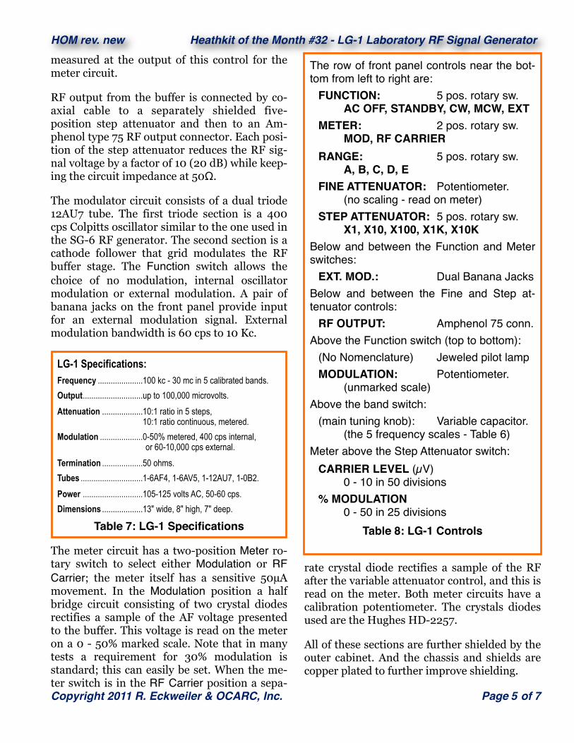
Fig. 4: LG-1 Schematic
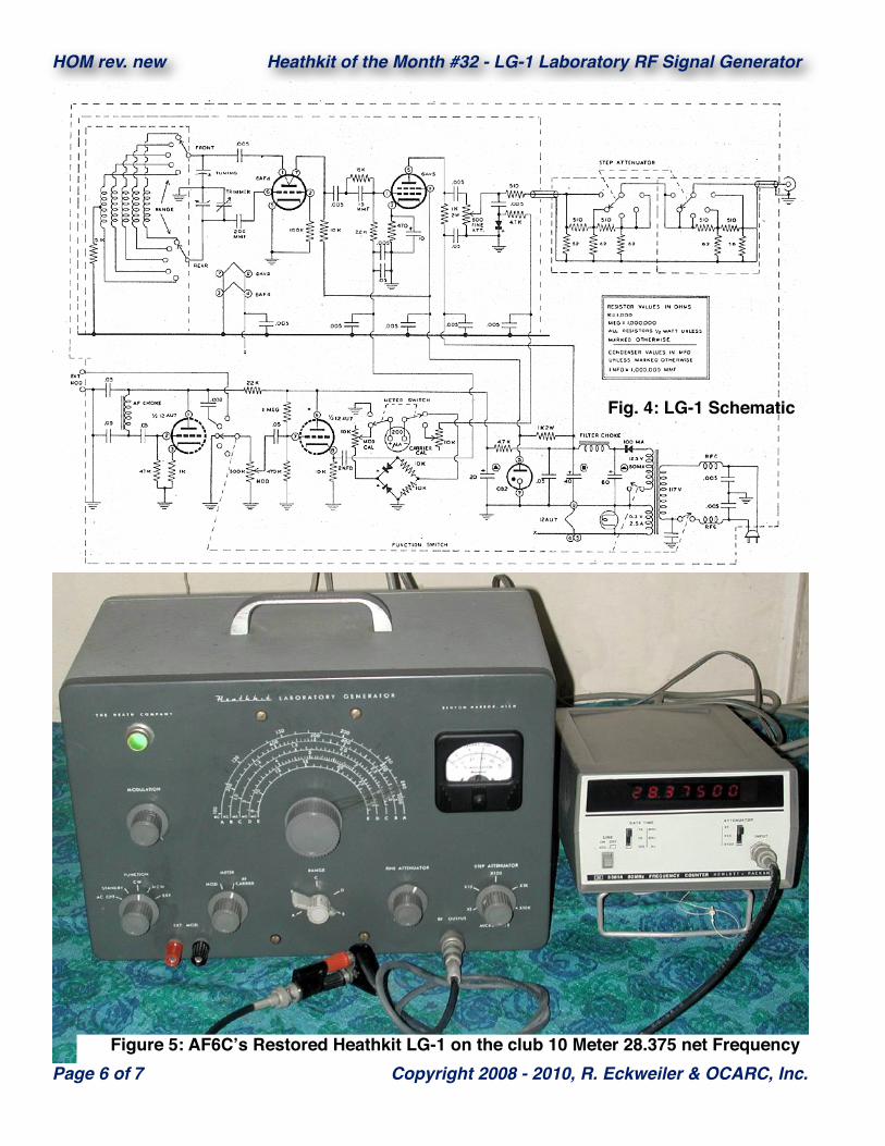
Figure 5: AF6Cʼs Restored Heathkit LG-1 on the club 10 Meter 28.375 net Frequency

Heath LG-1 Operation:Operation of the LG-1 is quite simple. Set the Range switch to the range covering the desired test signal and the dial to the desired fre-quency. Next set the desired level: Assume, say, you want a level of 500 µV; set the Fine Attenu-ator until the meter reads 5.0; then turn the Step Attenuator to the X100 position.
Setting the modulation, is as simple. On the Function switch select CW if no modulation is needed, MCW if you’d like internal 400 modu-lation or EXT if you want modulation from an external source. External modulation requires a few volts of audio be applied to the front panel EXT. MOD. banana jacks. Finally, if modulation is selected adjust the Modulation control until the meter reads the desired modu-lation percent.
Figure 5 shows a recently restored Heathkit LP-1, previously owned by Ray Davis - W6NT, connected to an HP frequency counter and set on the club 10 meter net frequency of 28.375 Mc. Notice the RF output cable that ends in a small black plastic case holding a 50Ω termi-nating resistor and dual binding posts.
Cleaning and lubricating switches and potenti-ometers is a big part or restoration. Restoring the LP-1 was a challenge due mainly to the ex-tensive shielding. To get access to certain com-ponents requires removing shields which in turn requires unsoldering components. It is important to take good notes or have the full manual. Many of the manuals that once fre-quented places on the web like BAMA (Boat Anchor Manual Archive) were only partial manuals and didn’t cover the step-by-step as-sembly with its component and wiring layout. Most of these are gone now that a company is said to have bought the copyright to all the old Heathkit manuals and has worked successfully to remove copies of the free manuals that used to be available in many places on the Internet.
Another challenge restoring this kit involved the vernier dial. The lubricant had dried out
and the vernier action was frozen causing the knob to operate the tuning capacitor directly. The vernier was removed and carefully cleaned. Unfreezing the vernier mechanism took a lot of patience and soakings in solvents and penetrat-ing oils. Finally when it freed up, the mecha-nism was carefully re-lubricated using a Lubri-Plate like white lithium grease. It has since worked smoothly and flawlessly.
Final Comments:Heathkit continued to build RF Generator kits. The RF-1 and later IG-102 are updated versions of the SG-8; the is IG-42, is a cosmetically up-dated version of the LP-1. These RF generators continued to be sold into the late seventies. Heathkit also make a low-end IG-5280 RF gen-erator as part of their low-cost 5280 series test bench up to the time they began phasing out kits.
Finally I’d like to thank John - W6JOR who passed some old Heathkit manuals along, in-cluding the GC-1A Mohican communications receiver and OL-1 3” Oscilloscope. We’ll be covering some of those kits in future articles.
Notes:1. Iʼve used the old frequency nomenclature of Mc and Kc and cps instead of MHz, KHz and Hz, since they were the nomenclature of the time period covered.
73, from AF6C
Remember if you come across any old Heathkit Manuals or Catalogs that you do not need, please pass them along to me.
Thanks - AF6C
This article originally appeared in the August 2011 issue of RF, the newsletter of the Or-ange County Amateur Radio Club - W6ZE.
HOM rev. new Heathkit of the Month #32 - LG-1 Laboratory RF Signal Generator
Copyright 2011 R. Eckweiler & OCARC, Inc. Page 7 of 7