heat transfer characteristics of multi-walled carbon nanotubes suspension in a developing channel...
TRANSCRIPT
ORIGINAL
Heat transfer characteristics of multi-walled carbon nanotubessuspension in a developing channel flow
Emad Elnajjar • Yousef Haik • Mohammad O. Hamdan •
Saud Khashan
Received: 29 October 2012 / Accepted: 27 July 2013 / Published online: 7 August 2013
� Springer-Verlag Berlin Heidelberg 2013
Abstract The present study experimentally investigates
the effect of multi wall carbon nanotubes (MWCNT) sus-
pensions on the convective heat transfer coefficients. The
MWCNT suspensions used in this study were prepared by
dispersing MWCNTs in deionized water 0.25 wt% arab
gum solution. The heat transfer characteristics were mea-
sured for thermally developing laminar flow in a finite
length horizontal circular pipe under isothermal wall con-
ditions. The study was conducted over a range of Reynolds
number of 300–2,300, based on 0.8 mm tube diameter.
Results indicate enhancements of the convective heat
transfer coefficient as a function of Reynolds number and
volume fractions. An average enhancement of heat transfer
coefficient of 50 % was observed over the base fluid. An
overall increase of pumping force varying from 20 to 30 %
over the flowing range is observed. The results suggest an
optimum MWCNT volume fraction point of 0.1 % which
gives the best heat transfer enhancement.
1 Introduction
Fluids in general have lower thermal conductivity com-
pared to solids; therefore, one of the promising methods of
enhancing heat exchanger efficiency is by improving the
thermo-physical properties of flowing fluids. Suspending
solid particles in a base fluid at very low concentrations is
used by different investigators to increase the overall
thermal conductivity [1]. The drawback of using suspended
millimeter particles in the fluid, is the development of a
high-pressure drop, which requires more pumping force.
Other shortcomings depending on the particles size and
concentration levels, include: clogging, abrasion and the
instability of the suspended particles. In the early nineties,
and after the recent development of nanotechnology, many
researchers [2–7, 15–18], studied the possibility of using
suspended nanoparticles in the base fluid (nanofluids), to
enhance the heat exchanger’s performance and reduce the
effect of these nanoparticles on the flow.
A number of theoretical and experimental studies that
investigate the heat transfer augmentation, thermo-physical
properties, and the increase of pumping force of nanofluids
are reported in the coming paragraphs.
Mohammed et al. [2], reviewed the theoretical and the
experimental work of the heat transfer using nanofluids,
and the flow characteristics in microchannel heat
exchangers. The study discussed the effects of channel
geometry, the fluid inlet and outlet arrangement, the
method of construction, type of nanofluids, method of
preparation, and mechanisms of enhancement. They stated
that the amount of work related to such an important and
promising topic and its applications is limited. They
stressed that the mechanism behind the heat transfer phe-
nomena in nanofluids is still not fully understood. And the
main reason behind the deviation in the researcher’s results
is due to the lack of standardization among different
studies.
Lee et al. [3], studied the effectiveness of using of
nanofluids in electronic cooling applications; where they
defined it as the scaling between the increase in the con-
vection augmentation factor and the adversary increase in
pumping power. By a direct measurement of thermal
conductivity and viscosity of different nanofluids types:
Al2O3, ZnO, and CuO and Carbon nanotubes, at different
volume percentage concentration levels, they reported an
E. Elnajjar (&) � Y. Haik � M. O. Hamdan � S. Khashan
Mechanical Engineering Department, United Arab Emirates
University, Al Ain, United Arab Emirates
e-mail: [email protected]
123
Heat Mass Transfer (2013) 49:1681–1687
DOI 10.1007/s00231-013-1212-1
increase in the effective convection coefficient of 5 % for
the 3 % volume fraction of Al2O3 nanoparticles in deion-
ized water (DW) nanofluid, 13.3 % for the 4 % volume
fraction of CuO nanoparticles dispersed in water nanofluid,
and 11.6 % for 0.2 % volume fraction of CNT suspended
in DW nanofluid.
Yang et al. [4], studied experimentally the heat transfer
of several nanoparticles dispersed in the transmission fluid,
and synthetic base-oils. The used nanoparticles were gra-
phitic in nature, within the aspect ratio of (l/d = 0.02), and
low loading ratio ranging from 2 to 2.5 wt%, flowing in a
horizontal laminar flow heat exchanger. The study shows a
low increase in the convective heat transfer coefficient as
compared to that predicted by other conventional heat
transfer correlations for homogenous nanofluids. They
conclude the need for more studies to develop an appro-
priate heat transfer correlation for the non-spherical nano-
particle dispersions.
Fotukian and Esfahany [5], experimentally studied the
convective heat transfer enhancement and pressure drop of
suspended CuO nanoparticles in a water base nanofluid.
The study was carried out with a turbulent flow inside a
5 mm circular tube. The study covered a range of flow
Reynolds number from 5,000 to 35,000, and nanoparticles
concentration range of 0.015–0.236 %. The study reported
a 25 % increase in the convective heat transfer coefficient
with a 20 % penalty in pressure drop.
Ding et al. [6], experimentally studied the heat transfer
of the aqueous suspension of multiwall carbon nanotubes
flowing through a horizontal tube. Arabic gum was used as
the dispersant in this work. The study suggested a signifi-
cant improvement of the convective heat transfer coeffi-
cient, the enhancements were related to the flow
conditions: Reynolds number (800–1,200), CNT concen-
tration (0, 0.1, 0.25, and 0.5 %.), and pH levels. The author
reported that the pH level shows the smallest effect on the
convective heat transfer coefficient. An enhancement of
350 % in the convective heat transfer coefficient for the
case of Reynolds number of 800 at CNT concentration of
0.5 %. Under similar operation condition the present work
reported an enhancement of 150 % of the heat transfer
coefficient. It is believed that the enhancement is due to the
increase of the thermal conductivity of the MWCNT sus-
pension, the particles re-arrangement, the shear which
induced thermal conduction enhancement, and the reduc-
tion in the thermal boundary layer due to the presence of
nanoparticles/MWCNT.
The present work is concerned on studying experimen-
tally the effect of different loading ratios of MWCNT
dispersed in a base fluid prepared using DW with 0.25 wt%
Arab Gum solution on the enhancement of the convective
heat transfer coefficient flowing in a thermally developing
flow in a straight horizontal finite length circular tube
subjected to constant surface temperature. This study
covers a range of flow Reynolds number of 300–2,300,
based on 0.8 mm tube diameter.
2 Experimental work
2.1 MWCNT suspension solution
The multi wall carbon nanotubes (MWCNT) used in the
present study were made by Carbon nanotubes Powder
Nano Lab, Inc. The nanotubes had a specified average
outside diameter of 10–30 nm, length of 0.5–20 lm and
purity of above 85 wt%, which was purchased from
NanoLab, Incorporation. In order to help dispersing the
MWCNT in DW and due to its hydrophobic nature [6],
surfactant agent is added to the MWCNT suspension,
which is used to change the wetting and the adhesion
behavior of the solution. Two types of surfactants were
used calcium chloride (CaCl), and arabic gum (AG), the
CaCl failed to produce a homogeneous MWCNT suspen-
sion for long period of time, where the MWCNT is sepa-
rated from the DW after a few minutes of preparation time.
Meanwhile, adding AG powder to the MWCNT suspension
with controlled ultrasonication and magnetic stirrers for
specific periods of time produces a stable, homogeneous
suspended solution for more than a month long period;
similar behavior is reported by other researchers [6, 7].
Ultrasonication and magnetic stirrer for controlled periods
of time were used to guarantee having untangled non
clustered MWCNT in the solution. The next paragraph
explains in details how the MWCNT suspension was
prepared.
In order to prepare 1 l of the MWCNT suspension with
0.1 wt% MWCNT, a 0.25 wt% solution of AG was added
to the DW where: 1 g of MWCNT and 2.5 g of AG were
dispersed in 996.5 g of DW. The mixture was put in a
magnetic stirrer for 10 min using (WiseStir MSH 20D) at
800 rpm, then the resulting composition was ultrasonicated
for 10 min using a 150 W, 20 kHz ultrasonic processor
(Branson SoniFier 450). The process of alternating
between the magnetic stirrer and ultrasonication is 10 min
periods within a total of a 40 min period. For more than a
month long period of preparing the MWCNT suspension
samples, using the above described technique for MWCNT
loading ratio of 0.05, 0.1, 0.15 and 0.2 % the MWCNT
suspension exhibited a stable and homogeneous mixture
without any signs of settling.
Figure 1 shows the zeta potential measurement using
Zetasizer Nano-ZS by Malvern Instruments for the base
fluid (DW), and the MWCNT suspension samples. The
results indicate that the base solution (DW) has a negative
charge, and the MWCNT suspension sample has a similar
1682 Heat Mass Transfer (2013) 49:1681–1687
123

charge which will create a repulsive force that keep the
MWCNT suspended in the base fluid. Figure 2 is an SEM
image for dried samples of 0.1 wt% MWCNT suspension
using JEOL JSM-5600 Scanning Electron Microscope at
10 kV for 15,000 magnifications. The SEM image suggests
that the MWCNTs are adsorbed with AG solution, which
prevents the agglomeration of the MWCNT and keeps it
suspended in the solution.
2.2 Experiment setup
To study the heat transfer performance of the MWCNT
suspension, a test setup was developed. A straight
0.8 mm diameter circular copper tube with a total length
of 52 cm is used. The tube was heated in a constant
temperature water bath of 100 �C constant temperature.
The water bath was controlled with a set of heaters and a
temperature controller to maintain a boiling water bath
temperature of 100 �C. A DC-pump is used to deliver the
fluid into the test tube; the pump has capacity range of
flow from 2 to 70 ml/s, which corresponds to a range of
Reynolds number of 800–2,500 respectively. The Rey-
nolds Number is defined as (U dp/mnf), where the U is the
average pipe flow velocity, dp is pipe diameter which is
equal to 0.8 mm and mnf is nanofluids kinematic viscos-
ity. The flow rate was metered directly by measuring the
time required for filling 100 ml glass vessel, the flow rate
was measured three times: during stabilization, at the
beginning of the run and at the end of the run. A k-type
thermocouple (Omega KT-12-39) was used to measure
the temperature of the hot bath, the inlet, and the outlet
flow. In order to minimize the error of the thermocouple,
all temperature measurements are performed using the
same thermocouple. The outlet flow is cooled by con-
necting the flow to a helical heat exchanger, to guarantee
a constant inlet flow temperature of 27 �C during the
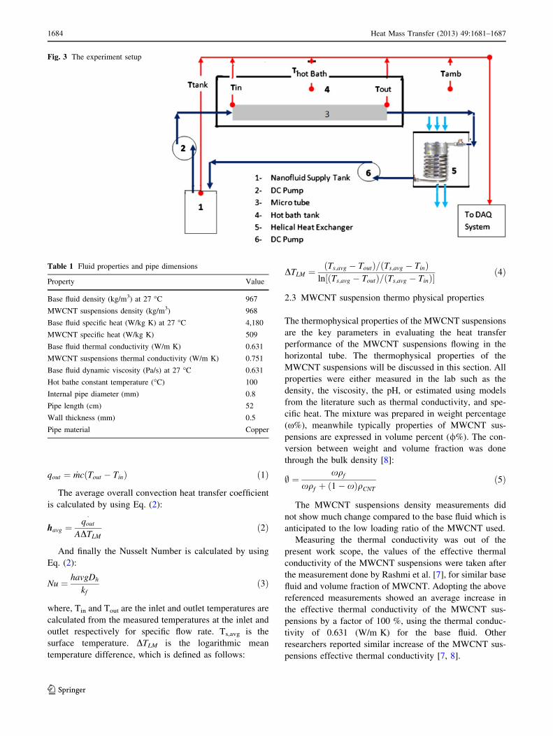
duration of the runs. Figure 3 shows a schematic diagram
of the experiment setup, with all used components. The
mean bulk properties of the base fluid and the MWCNT
are listed in Table 1. It is worth mentioning that the
reported uncertainty of the K-type OmegaTM thermo-
couples is ±0.3 �C, whereas, the uncertainty of the flow
rate measurements is estimated to be around
±0.001 LPM. Accordingly, the uncertainty with calcu-
lated Nusselt number averages to be ±5 %.
In this paragraph some the calculations and definitions
are described. The absorbed heat energy by the fluid is
calculated using Eq. (1):
Fig. 1 The zeta potential
measurement for a the base fluid
sample and b 0.05 % MWCNT
suspensions sample
Fig. 2 SEM image 10 kV, 915,000 of 0.05 % MWCNT, 2.5 wt%
AG/DI solution
Heat Mass Transfer (2013) 49:1681–1687 1683
123
qout ¼ _mcðTout � TinÞ ð1Þ
The average overall convection heat transfer coefficient
is calculated by using Eq. (2):
havg ¼qout�
ADTLM
ð2Þ
And finally the Nusselt Number is calculated by using
Eq. (2):
Nu ¼ havgDh
kf
ð3Þ
where, Tin and Tout are the inlet and outlet temperatures are
calculated from the measured temperatures at the inlet and
outlet respectively for specific flow rate. Ts,avg is the
surface temperature. DTLM is the logarithmic mean
temperature difference, which is defined as follows:
DTLM ¼ðTs;avg � ToutÞ=ðTs;avg � TinÞ
ln½ðTs;avg � ToutÞ=ðTs;avg � TinÞ�ð4Þ
2.3 MWCNT suspension thermo physical properties
The thermophysical properties of the MWCNT suspensions
are the key parameters in evaluating the heat transfer
performance of the MWCNT suspensions flowing in the
horizontal tube. The thermophysical properties of the
MWCNT suspensions will be discussed in this section. All
properties were either measured in the lab such as the
density, the viscosity, the pH, or estimated using models
from the literature such as thermal conductivity, and spe-
cific heat. The mixture was prepared in weight percentage
(x%), meanwhile typically properties of MWCNT sus-
pensions are expressed in volume percent (/%). The con-
version between weight and volume fraction was done
through the bulk density [8]:
; ¼xqf
xqf þ ð1� xÞqCNT
ð5Þ
The MWCNT suspensions density measurements did
not show much change compared to the base fluid which is
anticipated to the low loading ratio of the MWCNT used.
Measuring the thermal conductivity was out of the
present work scope, the values of the effective thermal
conductivity of the MWCNT suspensions were taken after
the measurement done by Rashmi et al. [7], for similar base
fluid and volume fraction of MWCNT. Adopting the above
referenced measurements showed an average increase in
the effective thermal conductivity of the MWCNT sus-
pensions by a factor of 100 %, using the thermal conduc-
tivity of 0.631 (W/m K) for the base fluid. Other
researchers reported similar increase of the MWCNT sus-
pensions effective thermal conductivity [7, 8].
Fig. 3 The experiment setup
Table 1 Fluid properties and pipe dimensions
Property Value
Base fluid density (kg/m3) at 27 �C 967
MWCNT suspensions density (kg/m3) 968
Base fluid specific heat (W/kg K) at 27 �C 4,180
MWCNT specific heat (W/kg K) 509
Base fluid thermal conductivity (W/m K) 0.631
MWCNT suspensions thermal conductivity (W/m K) 0.751
Base fluid dynamic viscosity (Pa/s) at 27 �C 0.631
Hot bathe constant temperature (�C) 100
Internal pipe diameter (mm) 0.8
Pipe length (cm) 52
Wall thickness (mm) 0.5
Pipe material Copper
1684 Heat Mass Transfer (2013) 49:1681–1687
123

The dynamic and kinematic viscosity of the base fluid
were measured by a SVM 300 Stabinger Viscometer at
three temperatures 30, 50 and 80 �C, the results suggest
that the base fluid viscosity is significantly dependent on
temperature. Unfortunately due to clogging problems in the
Viscometer, the MWCNT suspension’s viscosity was not
measured. It is approximated by adopting the model
developed by Xie and Chen [9]. It is assumed that the
effective MWCNT suspensions viscosity is a function of
the base fluid viscosity and the MWCNT volume fraction
which is given by the relation (6).
The effective heat capacity for the MWCNT suspen-
sions is calculated using the model developed by Liu et al.
[10], as expressed in Eq. (7), where / the MWCNT volume
fraction percentage and densities are measured for both
basic fluid and the MWCNT suspensions.
leff ¼lf
ð1� ;Þ2:5ð6Þ
Ceff ¼ Cf ð1� ;Þ þ ;CCNT ð7Þ
3 Results and discussion
Different researchers reported an improvement in the
convective heat coefficient, with insignificant increase of
the required pumping force, when using nanoparticles/CNT
with very small volume percentage to the base fluid. The
enhancement was mainly due to significant increases in the
thermal conductivity of the mixture (nanoparticles/CNT–
base fluid) which varies from 10 to 100 depending on the
type and the concentration of the nanoparticles/CNT
[3, 11].
An average increase in pumping force is estimated at
about 20–30 % for all flow cases covering a Reynolds
number range 300–2,300. The increase in pumping force is
evaluated by measuring the increase in input DC power of
the DC-pump.
The tube’s wall temperature, the inlet and the outlet flow
mixed cup temperatures for all the cases are showing in
Fig. 4. The results illustrate that to a large extent, the
micro-tube surface temperature is kept constant at 100 �C
during the experiment. The outlet flow temperatures of the
MWCNT suspensions are larger than the one for the basic
fluid for the same mass flow rate, and same wall temper-
ature. This demonstrates clearly that the MWCNT sus-
pensions absorbed more heat than when compared to the
basic fluid, and as a result, having higher effective thermal
conductivity and higher heat capacity of the MWCNT
suspensions than the ones for the basic fluid, this is
expected and reported with other investigators [6, 12, 13].
The results suggested a consistent enhancement of the
MWCNT suspensions compared to the basic fluid.
The average convective heat transfer coefficient results
as a function of different Reynolds number for the
MWCNT suspensions cases and the base fluid case are
displayed in Fig. 5. The average convective heat transfer
coefficient is calculated as a function of following mea-
sured parameters: the mass flow rate, the absorbed heat,
and the inlet, the outlet, the wall temperature and the sur-
face area of the micro-tube. The results show a clear
enhancement of the convective heat transfer above 45 %
compared to the base fluid case for all Reynolds number
range. Despite the fact that enhancement of the heat
transfer of MWCNT suspensions is documented by many
investigators, until now, no clear mechanism is claimed to
justify this enhancement; many factors may lead to such
behavior. To begin with, the change in effective thermal
conductivity can be a direct reason of this increase. Even
after stating this finding, the thermal conductivity of the
mixture is controlled by many parameters (the type, the
shape and the aspect ratio of nanoparticles/MWCNT,
the agglomeration, the liquid layering around the
0.0
0.2
0.4
0.6
0.8
1.0
300 700 1,100 1,500 1,900 2,300
T ou
t/T
wal
l
Re
Twall/Twall Tin/TwallBase Fluid 0.05%CNT0.1%CNT 0.15%CNT
Fig. 4 The micro-tube mixed cup outlet, inlet and surface normalized
temperature for different Reynolds numbers MWCNT suspensions
flow
0
1000
2000
3000
4000
5000
6000
7000
300 700 1,100 1,500 1,900 2,300
h (
W/m
2k)
Re
Base Fluid 0.05%CNT 0.1%CNT
0.15%CNT 0.2%CNT
Fig. 5 The experimental average convective heat transfer coefficient
versus Reynolds numbers for the MWCNT suspensions flow
Heat Mass Transfer (2013) 49:1681–1687 1685
123
nanoparticles/MWCNT, and the Browning motion) which
can have a positive or negative effect on its value.
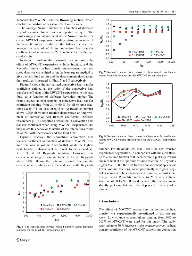
The average Nusselt number as a function of different
Reynolds number for all cases is reported in Fig. 6. The
results suggest an enhancement of the Nusselt number for
certain MWCNT suspensions loading ratios, the increase of
the Nusselt number is due to the balance between an
average increase of 45 % in convective heat transfer
coefficient and an increase in 22 % in the effective thermal
conductivity.
In order to analyze the measured data and study the
effect of MWCNT suspensions volume fraction, and the
Reynolds number on heat transfer enhancement, the mea-
sured data was curve fitted using the least square method to
give the best fitted results and the data is manipulated to get
the results as illustrated in Figs. 7 and 8 respectively.
Figure 7 shows the normalized convective heat transfer
coefficient defined as the ratio of the convective heat
transfer coefficient of the MWCNT suspensions to the base
fluid, as a function of different Reynolds number The
results suggest an enhancement of convective heat transfer
coefficient ranging from 20 to 60 % for all volume frac-
tions except for the case of 0.05 %. At Reynolds number
above 1,200 all volume fraction demonstrate an improve-
ment of convective heat transfer coefficient. Different
researchers [1, 14], reported a reduction in convective heat
transfer coefficient when using MWCNT suspensions and
they relate this behavior to nature of the interactions of the
MWCNT with themselves and the fluid flow.
Figure 8 displays the normalized convective heat
transfer coefficient as function of different MWCNT vol-
ume fractions. A volume fraction that yields the highest
heat transfer enhancement is found to be around /& 0.1 % at all Reynolds numbers. However, this
enhancement ranges from 42 to 55 % for all Reynolds
above 1,000. Below the optimum volume fraction, the
enhancement exhibits a clear dependence on the Reynolds
number. For Reynolds less than 1,000, the heat transfer
experiences degradation, in comparison with the clear flow,
up to a volume fraction of 0.05 % before it picks up toward
enhancement at the optimum volume fraction. At Reynolds
higher than 1,000, the heat transfer enhancement appears at
lower volume fractions, more profoundly at higher Rey-
nolds numbers. The enhancements diminish, almost iden-
tically for all Reynolds numbers, to 25 % at a volume
fraction of 0.15 %. Beyond which, the enhancement
slightly picks up but with less dependence on Reynolds
number.
4 Conclusions
The effect of MWCNT suspensions on convective heat
transfer was experimentally investigated in this present
work. Low volume concentrations ranging from 0.05 to
0.2 % of MWCNT were used for this study. The study
reported up to 50 % increase in the average convective heat
transfer coefficient of the MWCNT suspensions comparing
0
1
2
3
4
5
6
7
8
300 700 1,100 1,500 1,900 2,300
Nu
Re
Base Fluid 0.05%CNT 0.1%CNT
0.15%CNT 0.2%CNT
Fig. 6 The experimental average Nusselt number versus Reynolds
numbers for the MWCNT suspensions flow
0.0
0.2
0.4
0.6
0.8
1.0
1.2
1.4
1.6
1.8
300 700 1,100 1,500 1,900 2,300
h nf/
hf
Re
0.05%CNT 0.1%CNT0.15%CNT 0.2%CNT
Fig. 7 Normalize curve fitted convective heat transfer coefficient
versus Reynolds numbers for the MWCNT suspensions flow
0
4
0
4
0.
0.2
0.
0.6
0.8
1.
1.2
1.
1.6
1.8
h nf/
hf
0.00 0.05
Re=600Re=1800
0.10
%
Re=1000Re=2200
0.15 0.20
Re=1400
0.25
Fig. 8 Normalize curve fitted convective heat transfer coefficient
versus MWCNT volume fraction ratio for the MWCNT suspensions
flow
1686 Heat Mass Transfer (2013) 49:1681–1687
123
to the base fluid case, for flow Reynolds number above
1,200 for the case of 0.1 % volume fraction. The results
show that both volume fraction and Reynolds number are
major parameters affecting the augmentation of the heat
transfer in a laminar pipe flow. An optimum volume
fraction point of 0.1 % is observed for all used ranges of
Reynolds numbers which give the best heat transfer
enhancement. An average enhancement of 30 % is reported
for the Nusselt number of the MWCNT suspensions com-
paring to the base fluids case. Furthermore, our study
indicates for conditions at which there is enhancement and
others with degradation. For instance, the flow at Reynolds
number of 600 shows a degradation under dilute condi-
tions, while flows at Reynolds above 1,000 were showed
enhancement but with non-monotonic dependence with the
volume fraction.
References
1. Kakac S, Pramuanjaroenkij A (2009) Review of convective heat
transfer enhancement with nanofluids. Int J Heat Mass Transf
52:3187–3196
2. Mohammed HA, Bhaskaran G, Shuaib NH, Saidur R (2011) Heat
transfer and fluid flow characteristics in microchannels heat
exchanger using nanofluids: a review. Renew Sustain Energ Rev
15:1502–1512
3. Lee J, Gharagozloo PE, Kolade B, Eaton JK, Goodson KE (2010)
Nanofluid convection in microtubes. J Heat Transf 132:
092401–092405
4. Yang Y, Zhang G, Grulke E, Anderson W, Wu G (2005) Heat
transfer properties of nanoparticle-in-fluid dispersions (nanofl-
uids) in laminar flow. Int J Heat Mass Transf 48:1107–1116
5. Fotukian SM, Esfahany MN (2010) Experimental study of tur-
bulent convective heat transfer and pressure drop of dilute CuO/
water nanofluid inside a circular tube. Int Commun Heat Mass
Transf 37:214–219
6. Ding Y, Alias H, Wen D, Williams RA (2006) Heat transfer of
aqueous suspensions of carbon nanotubes (CNT nanofluids). Int J
Heat Mass Transf 49:240–250
7. Rashmi W, Ismail AF, Sopyan I, Jameel AT, Yusof F, Khalid M,
Mubarak NM (2011) Stability and thermal conductivity
enhancement of carbon nanotube nanofluid using gum Arabic.
J Exp Nanosci 6(6):567–579
8. Brinkman HC (1952) The viscosity of concentrated suspensions
and solutions. J Chem Phys 20:571–581
9. Xie H, Chen L (2009) Adjustable thermal conductivity in carbon
nanotube nanofluids. Phys Lett A 373:1861–1864
10. Liu M-S, Lin MC-C, Huang I-T, Wang C-C (2005) Enhancement
of thermal conductivity with carbon nanotube for nanofluids. Int
Commun Heat Mass Transf 32:1202–1210
11. Assael MJ, Chen CF, Metaxa I, Wakeham WA (2004) Thermal
conductivity of suspensions of carbon nanotubes in water. Int J
Thermophys 25(4):971–985
12. Amrollahi A, Rashidi AM, Lotfi R, Meibodi ME, Kashefi K
(2010) Convection heat transfer of functionalized MWNT in
aqueous fluids in laminar and turbulent flow at the entrance
region. Int Commun Heat Mass Transf 37:717–723
13. Keblinski P, Phillpot SR, Choi SUS, Eastman JA (2002) Mech-
anisms of heat transfer flow in suspensions of nano-sized particles
(nanofluids). Int J Heat Transf 45:855–863
14. Rea U, McKrell T, Hu L, Buongiorno J (2009) Laminar con-
vective heat transfer and viscous pressure loss of alumina–water
and zirconia–water nanofluids. Int J Heat Mass Transf 52:
2042–2048
15. Assael MJ, Metaxa I, Arvanitidis J, Christofilos D, Lioustas C
(2005) Thermal conductivity enhancement in aqueous suspen-
sions of carbon multi-walled and double-walled nanotubes in the
presence of two different dispersants. Int J Thermophys 26(3):
647–664
16. Choi SUS, Zhang ZG, Yu W, Lockwood FE, Grulke EA (2001)
Anomalous thermal conductivity enhancement in nanotube sus-
pensions. Appl Phys Lett 79(14):2252–2254
17. Garg P, Alvarado JL, Marsh C, Carlson TA, Kessler DA, An-
namalai K (2009) An experimental study on the effect of ultra-
sonication on viscosity and heat transfer performance of multi-
wall carbon nanotube-based aqueous nanofluids. Int J Heat Mass
Transf 52:5090–5101
18. Wen D, Ding Y (2004) Effective thermal conductivity of aqueous
suspensions of carbon nanotubes (carbon nanotube nanofluids).
J Thermophys Heat Transf 18(4):481–485
Heat Mass Transfer (2013) 49:1681–1687 1687
123