heat transfer and fluid flow characteristic in banks flat
TRANSCRIPT

Tikrit Journal of Engineering. Sciences/Vol.18/No.4/December 2011, (88-103)
Heat Transfer and Fluid Flow Characteristic in banks Flat Tubes Amer Jameel Shareef Abdulmajeed A. Ramadhan
Assistant Lecturer Assistant Lecturer
Mechanical Engineering Dept.- AL-Anbar University
Abstract
In this research a study effect of the length ratio (L/Da) and the height ratio (H/Da)
for banks flat tube heat exchanger In-Line and staggered arrangement on force
convection heat transfer and friction coefficient by (Fluent-CFD) numerical program.
The governing equations (mass, momentum and energy) are solving by using
Finite Volume (Fluent-CFD) software for considering steady state, two dimensional, at
constant heat flux with Reynold’s number (100≤Re≤8000).
The results show that increasing (H/Da), (L/Da) lead to decreasing friction coefficient
and enhancement of (Nu) is at (H/Da=2) for all (L/Da) values In-line arrangement and
at (H/Da =2, L/Da =5) for staggered arrangement.
Key words: banks flat tubes, convection heat transfer, and fluid flow.
انتقال الحرارة وجريان مائع لحزمة من الأنابيب المستوية الخلاصة
( لمبةةد رةاارذ و اابةب ة H/Da( والشةةو ل L/Daتضمن البحث دراسة تةير ا البةةب البة ة الة ل ة ج المةةح في تات خةةي وتخاةةللا ابخلةة الحةاارل مةلحمةس اللةةاذ وتلاةتةس اارخطةة الةةةحي ميسةخاما البابةةت
(. Fluent-CFDاللامدذ تةةح رةةس الملاةةةداك الحةعمةة تلاةدلةة ااسةةخماارل والةةطخح والةةوةة ( مةاللةة الح ةة المحةةمدل ب اسةةة البابةةةتج
ال الةةة ربةةةلي البلاةةم لاحةلةة المةةةخلال بةةم ربةة ك الاةة الحةةاارذ ابةب ةة المةةور را م تةةخ ااخةةو ببتةةا اا خبةةةر ا .(Re≤8000≥100)مالمبةد لممى مد رلب ل
( يؤدذ الى ابااةض في و م تلاةتس اارخطةك الةةحي, رمةة ا افضةس L/Da(و H/Daاظهاك البخةلج ا زلةدل H/Da =2 ,L/Da)( لاخات الاةي واتة لاخات المخاةللا L/Daل م خ و ح (H/Da=2)و م للامد بةات بم
=5). الكلمات الدالة: حزمة الانابيب المستوية, انتقال الحر ارة بالحمل القصري, جريان الموائع
88

Tikrit Journal of Engineering. Sciences/Vol.18/No.4/December 2011, (88-103)
Introduction
Tubular heat exchangers are used
in many energy conversion and
chemical reaction systems ranging from
nuclear reactors to refinery condensers.
The most important design variables of
tubular heat exchangers are the heat
transfer coefficient of the tube and the
pressure drop of the fluid flowing
externally. Based on previous studies
reported in the literature, the effects of
tube shape and arrangement have
indicated that they could have a positive
influence on heat transfer [1]. Flat tube
heat exchangers are expected to have
lower air-side pressure drop and better
air-side heat transfer coefficients
compared to circular tube heat
exchangers. The pressure drop is
expected to be lower than that for
circular tubes because of a smaller wake
area. For the same reason. A brief
preview of different studies involving
flow over a variety of shapes with
various types of flow conditions is
worth mentioning at this time for the
reader.
Merker and Hanke (1986)[2] found
experimentally the heat transfer and
pressure drop performance of staggered
oval tube banks with different
transversal and longitudinal spacing.
They showed that an exchanger with
oval-shaped tubes had smaller frontal
areas on the shell-side compared to
those with circular tubes. Chang, et al.
(1989)[3] has developed a numerical (by
finite element technique) to predict the
heat transfer and pressure drop
coefficient in cross flow through rigid
tube bundles. Results for heat transfer
and pressure drop coefficients are
obtained for tube arrays of pitch ratios
of 1.5 and 2 are very good agreement of
the predicted numerical results and
experimental data obtained. Chen, et al.
(1990)[4] numerically studied flow and
thermal fields in forced convection over
a heated cylinder for both
incompressible and compressible flow,
the governing equations included two-
dimensional Navier-Stokes momentum,
energy, and continuity equations in
body-fitted coordinates. The finite
Units Meaning Symbol Units Meaning Symbol
Pa Pressure P - Skin friction coefficient Cf
- Turbulent Prandtl
number Preff
m Small diameter Da
- Reynolds number ReDh
oC Temperature T m Long diameter Db
- Surface upper, lower
flat tube WU,WL m Hydraulic diameter Dh
/s
Cartesian velocity
components in x & y
axis ux,uy m Height H
kg/m3 Air density ρ W/m2.oC Heat transfer coefficient h
kg/s.m Viscosity µ W/m2.oC Thermal conductivity K
kg/s.m Effected Viscosity µeff m Length L
W/m2 Constant heat flux Hq - Average Nusselt Number Nu ave.
89
90
Tikrit Journal of Engineering. Sciences/Vol.18/No.4/December 2011, (88-103)
difference approximation for the
transformed conservation equation was
obtained by the integration over the
control volume. The velocity and
pressure fields were linked by the Semi-
Implicit Method for Pressure Linked
Equation (SIMPLE) algorithm. Kundu,
et al. (1991a)[5] numerically studied heat
transfer and fluid flow over a row of in-
line cylinders placed between two
parallel plates. Incompressible, two
dimensional, and laminar flow was
considered. The spacing between
cylinders causes three different
separation patterns, when the spacing is
small; the separated flow between
cylinders is stable. As the spacing
increases, flow in the separated zone
becomes periodic. At higher values of
spacing, the separated flow is local and
does not extend to the next cylinder.
The heat transfer data for different
aspect ratios and Reynolds numbers are
reduced to form a single formula for
ease of interpolation. Grannis and
Sparrow (1991)[6], for the fluid flow in a
heat exchanger consisting of an array of
diamond shaped pin-fins. The model
that underlines the solutions was based
on the concept of the periodically fully
developed regime, where by the
velocity field repeats itself from row to
row and the pressure drop per module
remains constant, the result included
representative streamline maps and
isobar and an in depth display of
pressure drop information. Yu, et al.
(1995)[7] applied the weighted residuals
method to analyze mixed convection
heat transfer in a 3x3 in-line horizontal
tube bundles placed between two
vertical parallel plates. The flow
regimes of Reynolds numbers up to 500
and Grashof numbers up to 53000 were
investigated and the local data of the
different geometries were reported. The
average Nusselt number for the array
increases 20-30% when stream wise
spacing was increased by 50%. Ertan
buyruk (1999)[8] an experimental study
was carried out to investigate heat
transfer and flow characteristics from
one tube within a staggered tube bundle
and within a row of similar tubes. The
tube spacing examined the longitudinal
pitches (St) and transverse pitches (Sl)
are (1.5-1.5), (1.5-1.25) respectively.
The variation of local Nusselt number
was predicted with Reynolds number
(4.8*104). The aim of the second part of
the investigation was to examine the
influence of the blockage of a single
tube in a duct and transverse pitch for a
single tube row with Reynolds number
range of (7960) to (47770). For single
tube row experiments, if the blockage
ratio is less than 0.5, the general shape
of local Nusselt number distribution
around the cylinder varies only slightly
with blockage. Castiglia, et al (2001)[9] the subcritical flow over an array of
elliptic cylinders with an axis ratio of
(1:2) was studied both experimentally
and numerically. The mean velocities,
turbulence levels and the vortex
dynamics of the array were determined
experimentally by flow visualization
and using a Laser Doppler Anemometer
(LDA) and the flow was modeled using
three-dimensional Large Eddy
Simulation (LES). The experimental
results were compared with results
obtained previously using circular
cylinders and with numerical
predictions of the flow. The study
indicated that the flow past such a
widely spaced array is characterized by
low turbulence levels, poor lateral
mixing compared with conventional
circular cylinder arrays, the predicted
mean, and velocities, as well as the flow
periodicity, were in good agreement
with the experimental results. Vikas
Kumar, et al (2003)[10] three
dimensional numerical simulation study
has been carried out to predict airflow
Tikrit Journal of Engineering. Sciences/Vol.18/No.4/December 2011, (88-103)
and temperature distribution in the tube
type heat exchanger. Due to symmetry
in geometrical construction, a section of
heat exchanger has been considered for
CFD analysis by using PHOENICS
software. The k - ε turbulence model
has been used to solve the transport
equations for turbulent flow energy and
the dissipation rate. The simulated
results predict the temperature
distribution reasonably at different
locations of heat exchanger. The CFD
model may be used to optimize its
thermal performance by varying the
location of baffles & partition plate in
the heat exchanger. Andrej , Borut
(2006)[11] Transient numerical
simulations of heat and fluid flow were
performed for eight heat exchanger
segments with cylindrical and wing-
shaped tubes in staggered arrangement.
Their hydraulic diameters were from
(0.5824 to 3.899) cm for the cylindrical
tubes, and from (0.5413 to 3.594) cm
for the wing-shaped tubes. In general,
the drag coefficient and the Stanton
number are smaller for the wing shaped
tubes than for the cylindrical tubes.
However, with an increasing hydraulic
diameter, these differences between
both forms of tubes diminish. Liang,
Papadakis (2007)[12]The Large Eddy
Simulation (LES) technique is used to
study the vortex shedding
characteristics inside a staggered tube
array consisting of six rows with
intermediate spacing (SL/D=1.6,
ST/D=3.6) at the subcritical Reynolds
number of 8600 (based on the gap
velocity). The filtered equations are
using the finite volume method in an
unstructured, collocated grid
arrangement with second-order accurate
methods in space and time. The
predictions of mean velocities and
Reynolds stresses are in very good
agreement with detailed LDA
measurements performed in 17 stations
along the depth of the array. The low
frequency component was present
behind all rows, the high component
was detected behind the first and second
rows only. Clearly, the fact that the flow
was allowed to develop along multiple
rows was instrumental for the
successful prediction of these two
shedding frequencies.
The main objective of this work is
numerical study to predict heat transfer
and friction coefficient characteristics of
flows around or through rigid complex
geometry (flat tube, Db=2Da), which
two-dimensional model created and
meshed in (Gambit) software. The
effects of various independent
parameters such as Reynolds number
(Re=100-8000), length ratio (L/Da= 5,
6, 7), and height ratio (H/Da= 2, 3, 4)
on friction coefficient and heat transfer
were studied by (Fluent-CFD) software.
Mathematical model
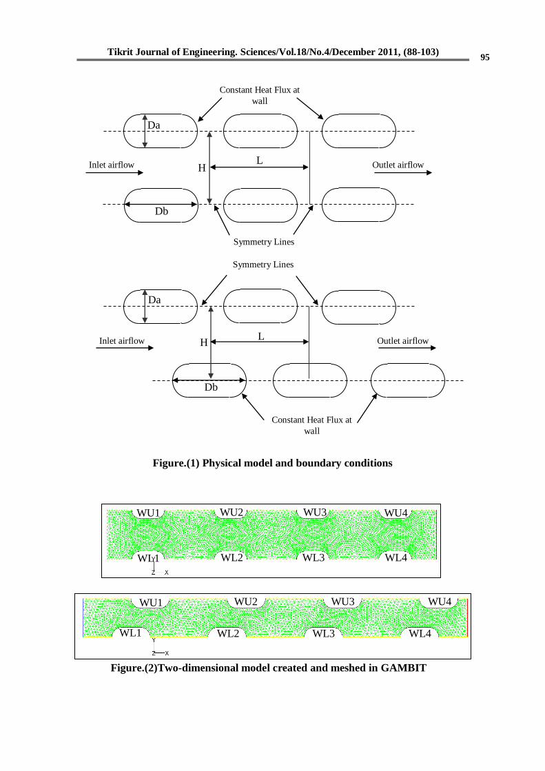
Consider banks tubes ranging
from a flat tube placed at in-lined and
staggered arrangement with cross
airflow. The wall of the flat tube is
heated under constant heat flux qH, and
air inlet at variable velocity Vx. The
physical model of the present problem
is illustrated in Fig. (1). The force
convection heat transfer between heated
flat tube surface and inlet airflow in a
horizontal x-y plane. The two-
dimensional governing equations were
summarized as follows under the
following assumptions [13, 14 and 15]
Steady state, the laminar, turbulent
flow, the fluid is incompressible, and
the viscous dissipation is negligible in
the energy equation, constant heat flux
at surface flat tube.
Key modeling equations in Fluent for
fluid flow and heat transfer from force
91
94
92
Tikrit Journal of Engineering. Sciences/Vol.18/No.4/December 2011, (88-103)
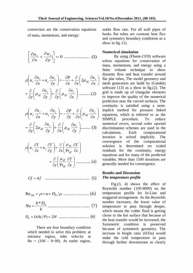
convection are the conservation equations
of mass, momentum, and energy:
)1(....................0
y
u
x
u yx
)2..(..........
2
x
u
yy
u
y
x
u
xx
P
y
uu
x
uu
y
eff
y
eff
xeff
xy
xx
)3(..........2
y
u
xy
u
y
x
u
xy
P
y
uu
x
uu
xeff
y
eff
y
eff
y
y
y
x
4...............Pr
Pr
y
T
y
x
T
xy
Tu
x
Tu
eff
eff
eff
eff
yx
5..............................................4 fCf
8................................2)4( HPAcDh
There are four boundary condition
which needed to solve this problem: at
entrance region, inlet velocity at
Re = (100 - 8000). At outlet region,
outlet flow rate. For all wall pipes of
banks flat tubes are constant heat flux
and symmetry boundary conditions as a
show in fig. (1).
Numerical simulation
By using (Fluent-CFD) software
solves equations for conservation of
mass, momentum, and energy using a
finite volume technique to show
dynamic flow and heat transfer around
flat plat tubes, The model geometry and
mesh generation are build by (Gambit)
software [13] as a show in fig.(2). The
grid is made up of triangular elements
to improve the quality of the numerical
prediction near the curved surfaces. The
continuity is satisfied using a semi-
implicit method for pressure linked
equations, which is referred to as the
SIMPLE procedure. To reduce
numerical errors, second order upwind
discrimination schemes are used in the
calculations. Each computational
iteration is solved implicitly. The
convergence of the computational
solution is determined on scaled
residuals for the continuity, energy
equations and for many of the predicted
variables. More than 1500 iterations are
generally needed for convergence.
Results and Discussion
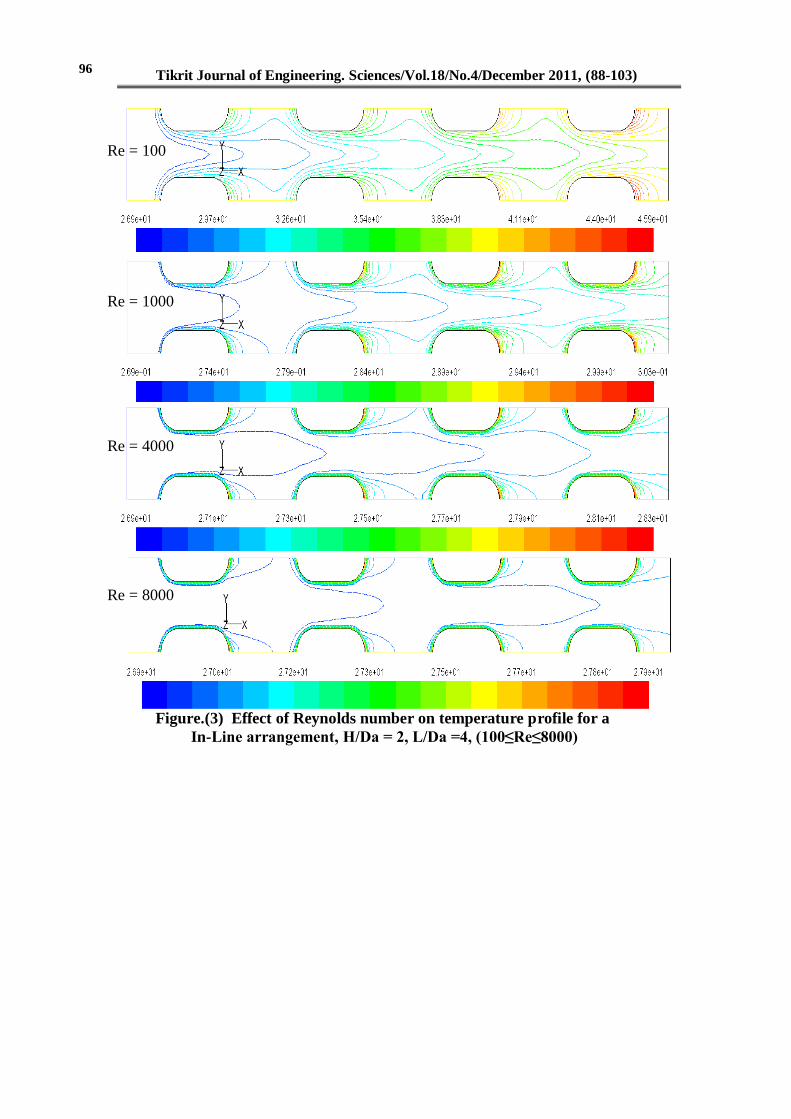
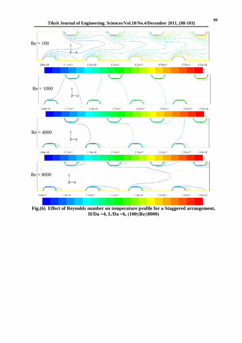
The temperature profile
Fig.(3, 4) shows the effect of
Reynolds number (100-8000) on the
temperature profile for In-Line and
staggered arrangement. As the Reynolds
number increases, the lower value of
temperature to pass through deeper,
which means the colder fluid is getting
closer to the hot surface that because of
the heat transfer would be increased, the
Symmetric condition is preserved
because of symmetric geometry. The
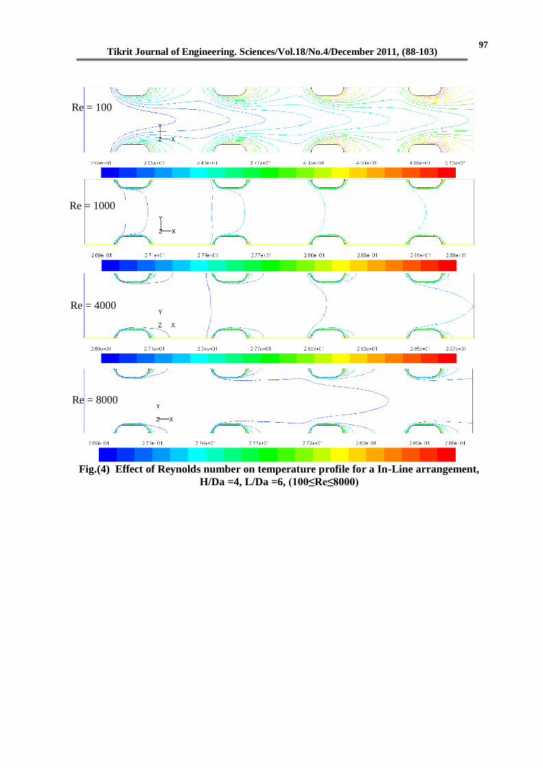
increase in height ratio (H/Da) would
make the cold temperature to pass
through further downstream as clearly
6.......................Re hDh Du
7......................................*
k
DhNu h
Tikrit Journal of Engineering. Sciences/Vol.18/No.4/December 2011, (88-103)
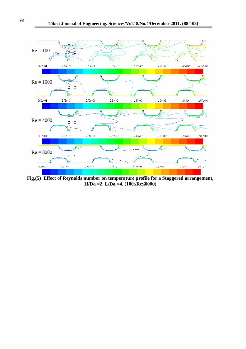
shown in Fig. (5). the effect of varying
length ratio (L/Da) is minimal on
temperature profile and thus does not
have much of an effect on heat transfer.
This behavior is more clear at higher
Reynolds numbers (Re = 8000). For the
staggered arrangement as shown in
Figs. (5, 6) It is marked that the lower
value of temperature to pass through
deeper compared with In-Line
arrangement.
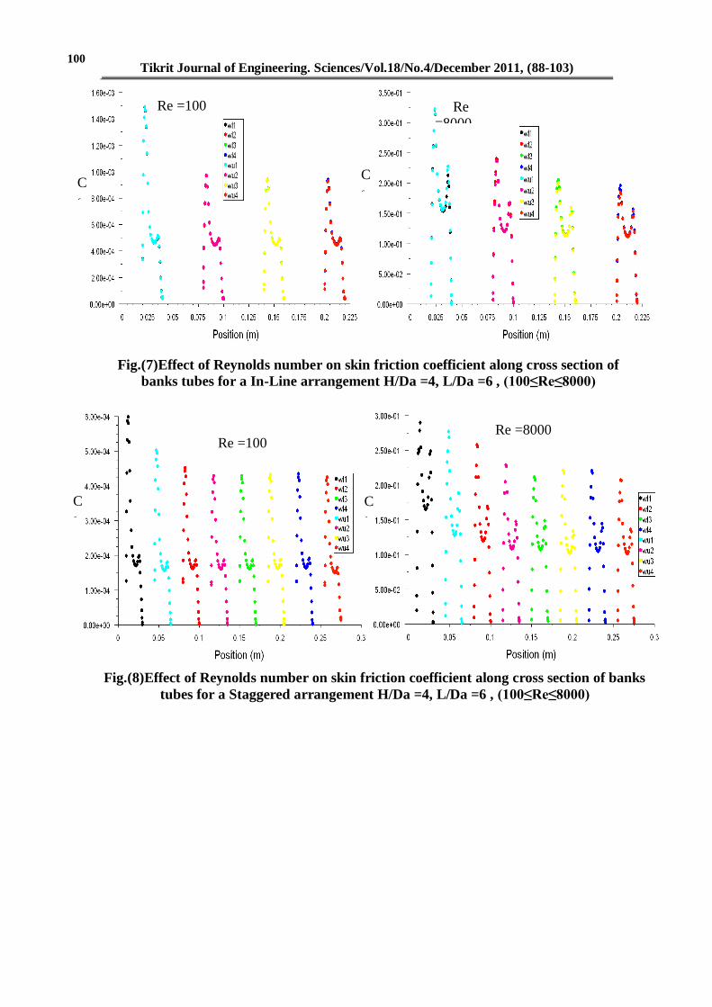
Skin friction coefficient (Cf)
Fig. (7, 8) show the effect of
Reynolds number (100-8000) flow on
Skin friction coefficient (Cf) for In-line
and staggered arrangement (H/Da=4,
L/Da=6). A higher (Cf) at first column
flat tube (WU1, WL1) and a lower (Cf)
at fourth column flat tube (WU4, WL4).
When increase (Re), Skin friction
coefficient is increased reaching
turbulent flow the value of (Cf)
approximation is the same for all
columns.
When increase height ratio (H/Da)
and length ratio (L/Da), the value of
(Cf) decrease because increasing in
distance between tubes of heat
exchanger that lead to fluid flow easily
and than low-pressure drop.
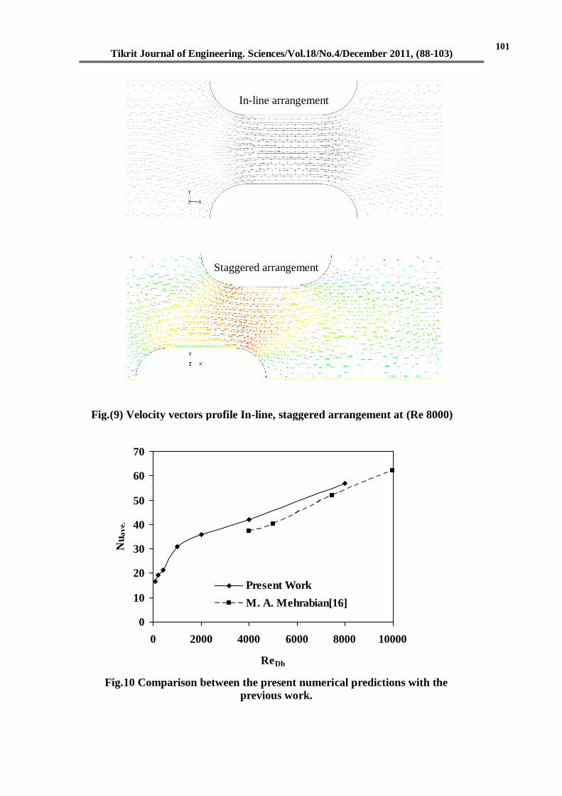
Fig. (9) indicate velocity vector
profile and made vortexes at end of
tubes are increase with increase (Re).
Average Nusselt Number
Fig. (10) Comparison between the
present numerical predictions with M.
A. Mehrabian, (2007) [16] and then
obtained a good agreement with this
previous work.
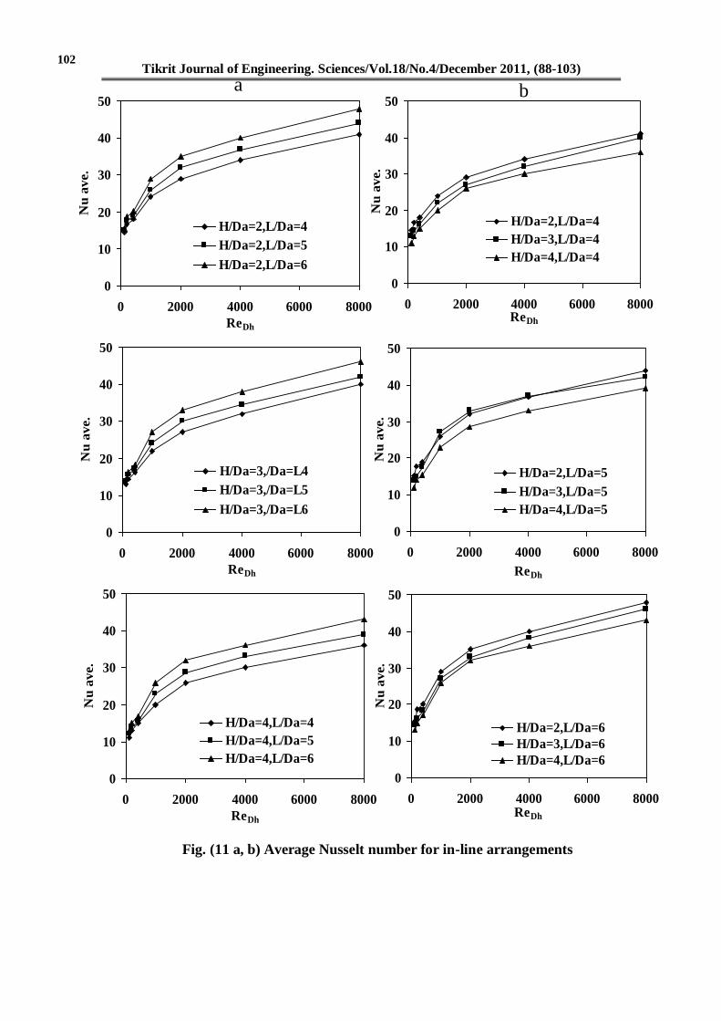
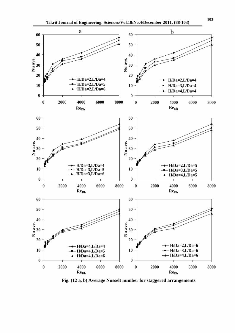
Fig. (11 a, b)(12 a, b) shows the
average Nusselt number (Nu) as a
function of Reynolds number (Re=100-
8000) for In-Line and staggered
arrangements, Fig. (11a)(12a) show the
effect of ratio length on the average
Nusselt number for fixed height ratios,
Fig. (11b)(12b) show the effect of ratio
height on the average Nusselt number
for fixed length ratios.
In general, the average Nusselt
number increases with an increase in
Reynolds number. The overall
performance of an in-line arrangement
with a lower height ratio (H/Da = 2) is
preferable since it provides higher heat
transfer rate for all length ratios and
Reynolds numbers as shown in
Fig.(11 a, b).
When increase of the length ratio
would result in a slight increase in
average Nusselt number at a lower
height ratio (H/Da = 2).
In staggered arrangement, the one
with minimum spacing between the
upper and lower tubes appears to give a
higher average Nusselt number if the
height and length ratios are maintained
at the lowest value (H/Da = 2 and L/Da
= 5) and at higher height and length
ratios (H/Da = 4 and L/Da = 6) the
staggered arrangement with the higher
spacing gives also a higher module
average Nusselt number as shown in
Fig. (12 a, b).
Conclusions
1- When increasing ratio (H/Da), the
cold temperature to pass through further
downstream but effect (L/Da) is
minimal on temperature profile.
2- For In-line arrangement,
enhancement of (Nu) is at (H/Da=2) for
all length ratios and Reynolds numbers;
as increase of (L/Da), a slight increase
in (Nu).
3- For staggered arrangement,
enhancement of (Nu) is at
(H/Da=2, L/Da = 4).
4- Skin friction coefficient is decreasing
when increasing ratios (H/Da), (L/Da).
References
1- Ota T., Nishiyama H., Kominami J.,
Sato K., 1986, "Heat Transfer Two
95
96
93
94

Tikrit Journal of Engineering. Sciences/Vol.18/No.4/December 2011, (88-103)
Elliptic Cylinder in Tandem
Arrangement" J. Heat
Transfer,Vol.108,PP. 525-531.
2- G. P. Merker, H. Hanke, 1986,
"Heat transfer and Pressure Drop on
the Shell-Side of Tube-Banks Having
Oval-Shaped Tubes" International
Journal of Heat and Mass Transfer,
Vol .29 (12), PP. 1903–1909.
3- Chang Y., Beris A.N., Michaelides
E.E., 1989, "A Numerical Study of
Heat and Momentum Transfer for
Tube Bundles in Cross-Flow” Int. J.
Num. Methods in Fluids Vol. 9,
PP.1381-1394.
4- Chen, Chiun-Hsun, Weng, Fang-Bor,
1990, "Heat Transfer for
Incompressible and Compressible
Fluid Flows Over a Heated Cylinder"
Num. Heat Transfer, Part A Vol. 18,
PP.325-349.
5- Kundu D., Haji-Sheikh A., Lou
D.Y.S., 1991a, "Heat Transfer
Predictions in Cross Flow Cver
Cylinders Between Two Parallel
Plates". Num. Heat Transfer, Part A
Vol. 19, PP. 361-377.
6- Grannis V.B., Sparrow E.M., 1991,
"Numerical Simulation of Fluid Flow
Through an Array of Diamond-
Shaped Pin Fins" Num. Heat
Transfer Part A Vol. 19, PP. 381-
403.
7- Yu, D., Barron, R.F., Ameel, T.A.,
Warrington, R.O., 1995, "Mixed
Convection From Horizontal Tube
Banks Between Two Vertical
Parallel Plates" Num. Heat Transfer,
Part A Vol. 27, PP.473-486.
8- Ertan Buyruk, 1997, "Heat Transfer
and Flow Structures Around Circular
Cylinders in Cross-Flow" Tr. J. of
Engineering and Environmental
Science Vol.23, PP.299 - 315.
9- D Castiglia, S Balabani, G Papadakis
and M Yianneskis, 2001, "An
Experimental and Numerical Study
of the Flow Past Elliptic Cylinder
Arrays" IMechE 2001 Proc Instn
Mech Engrs Part C Vol. 215.
10- Vikas Kumar1, D.
Gangacharyulu, Parlapalli MS Rao
and R. S. Barve, 2003, "CFD
Analysis of Cross Flow Air to Air
Tube Type Heat Exchanger".
11- Andrej Horvat and Borut
Mavko, 2006, "Drag Coefficient and
Stanton Number Behavior in Fluid
Flow a Cross a Bundle of Wing-
Shaped Tubes" Journal of Heat
Transfer Vol. by ASME 128 / 969.
12- C. Liang, G. Papadakis, 2007,
"Large Eddy Simulation of Cross-
Flow Through a Staggered Tube
Bundle at Subcritical Reynolds
Number" Journal of Fluids and
Structures Vol. 23, PP.1215–1230
13- Fluent 6.2, "FLUENT user’s
guide", Lebanon, Fluent Inc., USA,
2005.
14- Pantankar SV., 1980,
"Numerical Heat Transfer and Fluid
Flow" Hemisphere McGraw-Hill.
15- Launder B. E. and Spalding
D.B., 1974, "The Numerical
Computation of Turbulent Flows"
Computer Methods in Applied
Mechanics Engineering Vol. 3 PP.
269-289.
16- M. A. Mehrabian, 2007, "Heat
Transfer and Pressure Drop
Characteristic of Cross Flow of Air
Over a Circular Tube in Isolation
and/or in a Tube Bank" The Arabian
Journal for Science and Engineering,
Vol. 32, Number 2B.
Tikrit Journal of Engineering. Sciences/Vol.18/No.4/December 2011, (88-103)
Inlet airflow
Constant Heat Flux at
wall
Symmetry Lines
Outlet airflow L H
Db
Da
Figure.(1) Physical model and boundary conditions
L H Outlet airflow Inlet airflow
Db
Da
Constant Heat Flux at
wall
Symmetry Lines
Figure.(2)Two-dimensional model created and meshed in GAMBIT
WU4 WU3 WU2 WU1
WL1 WL2 WL3 WL4
WU4 WU3 WU2 WU1
WL1 WL2 WL3 WL4
95
Tikrit Journal of Engineering. Sciences/Vol.18/No.4/December 2011, (88-103)
Re = 100
Re = 4000
Re = 1000
Figure.(3) Effect of Reynolds number on temperature profile for a
In-Line arrangement, H/Da = 2, L/Da =4, (100≤Re≤8000)
Re = 8000
96
Tikrit Journal of Engineering. Sciences/Vol.18/No.4/December 2011, (88-103)
Fig.(4) Effect of Reynolds number on temperature profile for a In-Line arrangement,
H/Da =4, L/Da =6, (100≤Re≤8000)
Re = 100
Re = 1000
Re = 4000
Re = 8000
97
Tikrit Journal of Engineering. Sciences/Vol.18/No.4/December 2011, (88-103)
Fig.(5) Effect of Reynolds number on temperature profile for a Staggered arrangement,
H/Da =2, L/Da =4, (100≤Re≤8000)
Re = 100
Re = 1000
Re = 4000
Re = 8000
98
Tikrit Journal of Engineering. Sciences/Vol.18/No.4/December 2011, (88-103)
Fig.(6) Effect of Reynolds number on temperature profile for a Staggered arrangement,
H/Da =4, L/Da =6, (100≤Re≤8000)
Re = 100
Re = 1000
Re = 4000
Re = 8000
99
Tikrit Journal of Engineering. Sciences/Vol.18/No.4/December 2011, (88-103)
C
f
Re =100 Re =8000
C
f
Fig.(8)Effect of Reynolds number on skin friction coefficient along cross section of banks
tubes for a Staggered arrangement H/Da =4, L/Da =6 , (100≤Re≤8000)
Re =100
C
f
C
f
Fig.(7)Effect of Reynolds number on skin friction coefficient along cross section of
banks tubes for a In-Line arrangement H/Da =4, L/Da =6 , (100≤Re≤8000)
Re
=8000
100
Tikrit Journal of Engineering. Sciences/Vol.18/No.4/December 2011, (88-103)
In-line arrangement
Staggered arrangement
Fig.(9) Velocity vectors profile In-line, staggered arrangement at (Re 8000)
Fig.10 Comparison between the present numerical predictions with the
previous work.
0
10
20
30
40
50
60
70
0 2000 4000 6000 8000 10000
ReDh
Nu
av
e.
Present Work
M. A. Mehrabian[16]
101
Tikrit Journal of Engineering. Sciences/Vol.18/No.4/December 2011, (88-103)
0
10
20
30
40
50
0 2000 4000 6000 8000
ReDh
Nu
av
e.
H/Da=2,L/Da=4
H/Da=2,L/Da=5
H/Da=2,L/Da=6
0
10
20
30
40
50
0 2000 4000 6000 8000
ReDh
Nu
av
e.
H/Da=3,/Da=L4
H/Da=3,/Da=L5
H/Da=3,/Da=L6
0
10
20
30
40
50
0 2000 4000 6000 8000
ReDh
Nu
av
e.
H/Da=4,L/Da=4
H/Da=4,L/Da=5
H/Da=4,L/Da=6
0
10
20
30
40
50
0 2000 4000 6000 8000ReDh
Nu
av
e.
H/Da=2,L/Da=4
H/Da=3,L/Da=4
H/Da=4,L/Da=4
0
10
20
30
40
50
0 2000 4000 6000 8000
ReDh
Nu
av
e.
H/Da=2,L/Da=5
H/Da=3,L/Da=5
H/Da=4,L/Da=5
0
10
20
30
40
50
0 2000 4000 6000 8000ReDh
Nu
av
e.
H/Da=2,L/Da=6
H/Da=3,L/Da=6
H/Da=4,L/Da=6
a b
Fig. (11 a, b) Average Nusselt number for in-line arrangements
102
Tikrit Journal of Engineering. Sciences/Vol.18/No.4/December 2011, (88-103)
0
10
20
30
40
50
60
0 2000 4000 6000 8000
ReDh
Nu
av
e.
H/Da=2,L/Da=4
H/Da=2,L/Da=5H/Da=2,L/Da=6
0
10
20
30
40
50
60
0 2000 4000 6000 8000
ReDh
Nu
av
e.
H/Da=3,L/Da=4H/Da=3,L/Da=5H/Da=3,L/Da=6
0
10
20
30
40
50
60
0 2000 4000 6000 8000
ReDh
Nu
av
e.
H/Da=4,L/Da=4H/Da=4,L/Da=5H/Da=4,L/Da=6
0
10
20
30
40
50
60
0 2000 4000 6000 8000
ReDh
Nu
av
e.
H/Da=2,L/Da=4
H/Da=3,L/Da=4
H/Da=4,L/Da=4
0
10
20
30
40
50
60
0 2000 4000 6000 8000
ReDh
Nu
av
e.
H/Da=2,L/Da=5H/Da=3,L/Da=5H/Da=4,L/Da=5
0
10
20
30
40
50
60
0 2000 4000 6000 8000
ReDh
Nu
av
e.
H/Da=2,L/Da=6
H/Da=3,L/Da=6H/Da=4,L/Da=6
a b
Fig. (12 a, b) Average Nusselt number for staggered arrangements
103