heart rate estimation using wrist-acquired photoplethysmography under different...
TRANSCRIPT

Heart Rate Estimation Using Wrist-acquiredPhotoplethysmography Under Different Types of
Daily Life Motion ArtifactZhe Lin§, Jin Zhang†,Yanjiao Chen§, and Qian Zhang§
§Department of Computer Science and Engineering, Hong Kong University of Science and Technology†Department of Electrical and Electronic Engineering South University of Science and Technology of China
Email: [email protected], [email protected], [email protected], [email protected]
Abstract—Reflective wrist photoplethysmograph (PPG), ob-tained by a watch or wristband, can provide a natural andunconstrained way for daily life heart rate monitoring. However,reflective wrist PPG often suffers from poor signal quality andvarious distortions due to daily life motion artifact. In this paper,we analyze the influence of motion artifact on reflective wristPPG signals, and propose a method to extract reliable heartrate from such distorted PPG signals. The proposed methodconsists of adaptive filtering, heart rate selection, and motionidentification. Experimental results show that our proposedmethod can generate reliable heart rate values from wrist PPGsignals with different types of motion artifact.
I. INTRODUCTION
A. Background
Heart rate is one of the most significant physical signsthat are related to human health. Heart rate monitoring areoften conducted in the clinical environment where the heartrate of the patient is recorded for doctor to give diagnosis.Monitoring heart rate is not only important for the patient butalso beneficial for common people. With the development ofthe sensor technology, some simple portable devices [1], [2]emerged on the market, enabling people to measure their ownheart rate at home. Some products are developed for long-term heart rate monitoring in daily life [3]. Wearable devicesfor health monitoring would be a trend for telehealth in thefuture.
Photoplethysmography (PPG) is often used for heart ratemeasurement [4]. The basic principle of PPG is that differentlight absorption rate caused by changes of blood flow in themicrovascular vessel could be detected by photodiode (PD).According to different traverse path of the received light,PPG could be classified into two different modes: reflectedmode and transmitted mode. In the transmitted mode, the lighttransmits through the tissue, and is received by the PD placedon the opposite side of the body. In the reflected mode, thePD and the light source are located on the same side of thebody. PD receives the light reflected by the skin. Comparedwith reflected mode, transmitted mode can achieve a relatively
better signal. Since the light needs to transmit through thetissue, PPG obtained by the transmitted mode can only bemeasured from limited parts of the body, such as fingertip andearlobe.
B. Related Work
Reflected mode PPG does not have the limited placementproblem of the transmitted mode PPG. However, reflectedmode is more sensitive to motion artifact and pressure dis-turbances. Physical activity introduces motion artifact whichdistorts the PPG signal and makes it harder to extract usefulphysiological parameters. In [5], the authors designed anearpiece PPG sensor to record the PPG signal from ear. In[6], the authors used forehead reflectance PPG to monitor heartrate. In [7], the authors analyzed the correlation of the PPGand the acceleration signal in frequency domain, and proposeda method to estimate heart rate using the reflective PPGsignal acquired from the finger. Their method could producean acceptable heart rate under motion artifact. However, afingertip is needed to acquire PPG signal acquired fromthe finger. Wearing a fingertip will greatly affect the user’scomfort level as many of our daily life activities involve fingermovement.
Amongst all the common body parts for PPG measurement,wrist is an ideal site for long-term measurement in ourdaily life. PPG sensor could be embedded into a watch ora wristband that are worn by the users most naturally. Itneither make people look odd (like the sensors on the earlobeor head), nor limit users’ activities (like the sensors on thefingertip). In [8], the authors tried to estimate heart rate fromthe PPG signals obtained from the wrist during walking. Theirmethod is similar to the method in [7], which compares theacceleration and PPG in frequency domain to eliminate motionartifact.
C. Challenges and Contributions
The major challenge to extract heart rate from the PPGobtained from the wrist is to deal with the motion artifact.

Fig. 1. Flow chart of the proposed method
In [9], the author compared the motion artifact effect ondifferent measurement site and reported that PPG signal fromthe wrist has the worst signal quality in terms of motionartifact compared with finger, upper arm and forearm. Variousmethods had been proposed to deal with motion artifact in PPGsuch as singular value decomposition (SVD) [10], independentcomponent analysis (ICA) [11], wavelet decomposition [12],and active noise cancellation [13]. These methods are onlyapplied to the PPG from the finger which had much lessmotion artifact than the wrist. They may not be able to handlePPG from the wrist with various daily life motion artifact. Inrecent works [7], [8], acceleration signal had been leveraged todeal with motion artifact in PPG in the frequency domain. Theauthors only validated their method under running scenario.Whether the proposed method is useful for other types ofmotion artifact is unknown.
In some preliminary tests we conducted, we gained thefollowing observation. In most motion distorted PPG signal’sspectrum, heart rate component still exists clearly. If we coulddifferentiate heart rate component from the motion artifact, wecould extract reliable heart rate from the distorted PPG signal.Our major contribution are three folds:• We design a novel heart rate detection algorithm which
could identify heart rate component under various typesof motion artifact.
• We leverage active noise cancellation method to enhancethe signal quality for the postprocessing of our algorithm.
• Experimental results show that our proposed method cangenerate reliable heart rate values from wrist PPG signalswith different types of motion artifact.
II. METHODOLOGY
A. Overall Design
Fig. 1 shows the main procedures of our heart rate extractionmethod. To start with, raw PPG and acceleration signals arecaptured simultaneously. Raw PPG signals are then fed intothe adaptive filter to reduce the noise outside the heart ratefrequency band. After that, filtered signals are divided intosmall segments for Fast Fourier Transform (FFT) to obtainthe spectrum of the filtered PPG segments. Meanwhile theacceleration signals go through a walking detection algorithmto identify whether the user is walking. Based on the resultfrom the walking detection algorithm, we will select a heartrate detection algorithm to process the generated filtered PPGspectrum. Finally, we will get the estimated heart rate fromthe heart rate detection algorithm. Next, we will describe eachprocedure in detail.
B. Active Noise CancellationTo enhance the signal quality for postprocessing the algo-
rithm, we leverage the active noise cancellation technique. The
Algorithm 1 Heart Rate Search Algorithm1: Incoming PPG signals with body status tag.2: if Body status is non-walking then3: Update 1s PPG and Conduct 30s FFT.4: Select 0.83− 3.33Hz band of spectrum.5: Let P denote the set of frequency values in the band,
and Pmax denote the frequency in P with the maximummagnitude.
6: P1 = Pmax,P = P \ {P1}.7: P2 = Pmax,P = P \ {P2}.8: while |P1 − P2| < 0.3 do9: P2 = Pmax,P = P \ {P2}.
10: end while11: P3 = Pmax,P = P \ {P3}.12: while |P1 − P3| < 0.3 and |P2 − P3| < 0.3 do13: P3 = Pmax,P = P \ {P3}.14: end while15:
Pi = argminp∈{P1,P2,P3}
|p− Pi−1|
16: Smooth Pi as: Pi = 2−9Pi−9 +∑8
j=0 Pi−j2−j−1
17: if |Pi − Pi−1| > 0.5 then18: Pi = Pi−119: end if20: Calculate heart rate Hri by Pi
21: else22: if Body status is walking then23: Let P0 be the last stable frequency before walking.24: if Walking duration is fewer than 100s then25: Record PPG.26: end if27: if Walking duration is 100s then28: Conduct 60s FFT on 40s-100s PPG during walk-
ing.29: Select 1− 2Hz band of spectrum.30: P stable = Pmax.31: Calculate walking stable heart rate Hrstable by
P stable for 40s-100s during walking.32: Calculate walking rising heart rate Hrrising for
0s-40s during walking by linear fitting on P0 andP stable.
33: end if34: if Walking duration is greater than 100s then35: Update 10s PPG and conduct 60s FFT.36: Select 1-2Hz band of spectrum.37: P stable
i = Pmax
38: Calculate walking stable heart rate Hrstablei byP stablei for these 10s during walking.
39: end if40: end if41: end if
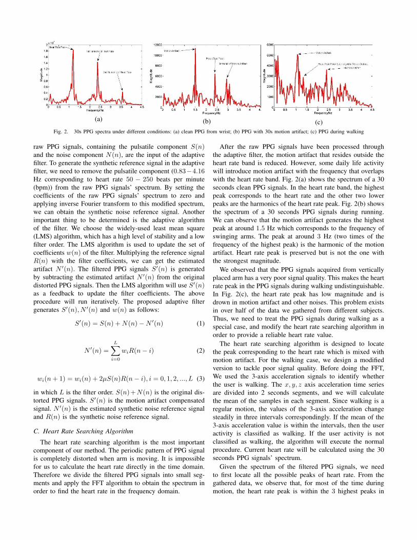
(a) (b) (c)Fig. 2. 30s PPG spectra under different conditions: (a) clean PPG from wrist; (b) PPG with 30s motion artifact; (c) PPG during walking
raw PPG signals, containing the pulsatile component S(n)and the noise component N(n), are the input of the adaptivefilter. To generate the synthetic reference signal in the adaptivefilter, we need to remove the pulsatile component (0.83−4.16Hz corresponding to heart rate 50 − 250 beats per minute(bpm)) from the raw PPG signals’ spectrum. By setting thecoefficients of the raw PPG signals’ spectrum to zero andapplying inverse Fourier transform to this modified spectrum,we can obtain the synthetic noise reference signal. Anotherimportant thing to be determined is the adaptive algorithmof the filter. We choose the widely-used least mean square(LMS) algorithm, which has a high level of stability and a lowfilter order. The LMS algorithm is used to update the set ofcoefficients w(n) of the filter. Multiplying the reference signalR(n) with the filter coefficients, we can get the estimatedartifact N ′(n). The filtered PPG signals S′(n) is generatedby subtracting the estimated artifact N ′(n) from the originaldistorted PPG signals. Then the LMS algorithm will use S′(n)as a feedback to update the filter coefficients. The aboveprocedure will run iteratively. The proposed adaptive filtergenerates S′(n), N ′(n) and w(n) as follows:
S′(n) = S(n) +N(n)−N ′(n) (1)
N ′(n) =
L∑i=0
wiR(n− i) (2)
wi(n+ 1) = wi(n) + 2µS(n)R(n− i), i = 0, 1, 2, ..., L (3)
in which L is the filter order. S(n)+N(n) is the original dis-torted PPG signals. S′(n) is the motion artifact compensatedsignal. N ′(n) is the estimated synthetic noise reference signaland R(n) is the synthetic noise reference signal.
C. Heart Rate Searching Algorithm
The heart rate searching algorithm is the most importantcomponent of our method. The periodic pattern of PPG signalis completely distorted when arm is moving. It is impossiblefor us to calculate the heart rate directly in the time domain.Therefore we divide the filtered PPG signals into small seg-ments and apply the FFT algorithm to obtain the spectrum inorder to find the heart rate in the frequency domain.
After the raw PPG signals have been processed throughthe adaptive filter, the motion artifact that resides outside theheart rate band is reduced. However, some daily life activitywill introduce motion artifact with the frequency that overlapswith the heart rate band. Fig. 2(a) shows the spectrum of a 30seconds clean PPG signals. In the heart rate band, the highestpeak corresponds to the heart rate and the other two lowerpeaks are the harmonics of the heart rate peak. Fig. 2(b) showsthe spectrum of a 30 seconds PPG signals during running.We can observe that the motion artifact generates the highestpeak at around 1.5 Hz which corresponds to the frequency ofswinging arms. The peak at around 3 Hz (two times of thefrequency of the highest peak) is the harmonic of the motionartifact. Heart rate peak is preserved but is not the one withthe strongest magnitude.
We observed that the PPG signals acquired from verticallyplaced arm has a very poor signal quality. This makes the heartrate peak in the PPG signals during walking undistinguishable.In Fig. 2(c), the heart rate peak has low magnitude and isdrown in motion artifact and other noises. This problem existsin over half of the data we gathered from different subjects.Thus, we need to treat the PPG signals during walking as aspecial case, and modify the heart rate searching algorithm inorder to provide a reliable heart rate value.
The heart rate searching algorithm is designed to locatethe peak corresponding to the heart rate which is mixed withmotion artifact. For the walking case, we design a modifiedversion to tackle poor signal quality. Before doing the FFT,We used the 3-axis acceleration signals to identify whetherthe user is walking. The x, y, z axis acceleration time seriesare divided into 2 seconds segments, and we will calculatethe mean of the samples in each segment. Since walking is aregular motion, the values of the 3-axis acceleration changesteadily in three intervals correspondingly. If the mean of the3-axis acceleration value is within the intervals, then the useractivity is classified as walking. If the user activity is notclassified as walking, the algorithm will execute the normalprocedure. Current heart rate will be calculated using the 30seconds PPG signals’ spectrum.
Given the spectrum of the filtered PPG signals, we needto first locate all the possible peaks of heart rate. From thegathered data, we observe that, for most of the time duringmotion, the heart rate peak is within the 3 highest peaks in

the heart rate band. Thus, we begin by finding the highest peakP1 and the second highest peak P2. If the distance betweenP2 and P1 is smaller than the threshold 0.3 Hz, P2 will bediscarded, and we will find the next highest peak for P2. Thedistance threshold is set to avoid selecting peaks that are tooclose to each other. P3 is the next highest peak after P2, alsoconforming with the distance condition. After P1, P2, P3 areselected, the one with the shortest distance to the previousselected peak Pi−1 will be chosen. Because the algorithmupdate heart rate second by second, within such short period oftime, the heart rate is not likely to change dramatically. If wechoose the heart rate peak entirely based on Pi−1, there willbe high chance that the selection error will propagate throughthe following selections. So we smooth Pi by the exponentialweighted average of the last 10 seconds’ heart rate, and add asaltation penalty to avoid dramatic heart rate change within ashort period of time. Finally, the heart rate is calculate by thefrequency of the modified Pi.
For the PPG signals during walking, the above algorithmwill result in great error because the heart rate peak is usuallydrown in the motion artifact and other noises. We handlethis problem based on the following observation. Duringregular motion like walking, the heart rate will go throughtwo stages: rising period and stable period. During the risingperiod, the heart rate will go up rapidly within the first 30seconds. The duration of rising period varies in differentindividuals and for different motion intensity. If the motionintensity does not change much, such as walking with a steadyvelocity, the heart rate will enter a stable period that only haslittle heart rate variation. As the heart rate changes rapidlyduring rising period, the energy of heart rate disperses andcannot accumulate a strong magnitude in the spectrum. Butin the stable period, heart rate varies little so it can form adistinguishable peak in the spectrum. We differentiate risingperiod and stable period at the point of 40 seconds duringwalking. Then we will conduct FFT using the first 60 secondsof PPG during stable period (40 seconds to 100 seconds).We can not locate the heart rate by finding the peak withthe shortest distance with the previous peak, because duringwalking, heart rate is updated less frequently. However, thenormal heart rate during walking is between 60-120 bpm. Withthis knowledge, we can narrow the searching range to 1-2Hz.Also, the major motion artifact caused by walking is mostlyless than 1Hz, so the heart rate peak will be the dominantcomponent within the 1-2Hz band. Thus, we will select thehighest peak within a 1-2Hz to generate the heart rate in thestable period. The first 60 seconds’ heart rate during stableperiod will be all set to the same value. After that, heart ratewill be updated every 10 seconds using the same strategy. Wecompromise the updating frequency for a reliable heart ratevalue. The 40 seconds rising period heart rate will be calulatedby using the last heart rate before walking and the first heartrate in the stable period. Since the rising period lasts less thana minute and the heart rate is monotonically increasing, it issufficient to use the above two values and the linear fitting toreconstruct the heart rate in the rising period.
III. EXPERIMENTS
A. Materials and Setup
The experimental PPG monitoring system consists of twoPPG sensors, two control boards and one 3-axis accelerometer.The PPG sensor we used is called Pulse Sensor, which is aplug-and-play device developed by an open source hardwareproject. We chose Bluno Nano as the control board, whichis designed based on another open source hardware ArduinoUno. It is embedded with BT 4.0 (BLE) module so that the ac-quired data can be exported via Bluetooth. The accelerometerwe used is ADXL345 module from Analog Devices.
Fig. 3 shows the experiment scenario. One Pulse Sensor isattached on the left arm wrist to record the wrist PPG signals.It is connected to the Bluno Nano control board throughdupont wire. The accelerometer is also attached on the leftwrist next to the Pulse Sensor and connected to the BlunoNano control board. Another Pulse Sensor is attached on theright hand finger, also connected to the Bluno Nano controlboard. The other Bluno Nano control board is connected tothe laptop. The analog signals acquired by the Pulse Sensorand the accelerometer will be processed by the MCU’s ADCfunction of the control board with a sampling rate of 125Hz.Then the signals will be transmitted out and received bythe Bluno Nano that connected to the laptop. The laptopwill record the data and perform offline processing usingMATLAB.
Fig. 3. Experiment scenarioB. Motion Classification
Daily life activities contain various sophisticated motions.We mainly focus on the motions that will affect wrist PPGsignals. We classify daily life motions into two categories: armmotion and body motion. The arm motion does not containthe motions from other parts of the body and it only lastsfor a shorts period of time (a few seconds). The intensity ofarm motion is relatively low compared to body motion. Forbody motion, we refer to walking and running. Body motionis regular, and usually lasts from tens of seconds to severalminutes, or even longer.

Fig. 4. (a) Fig. 5. (b) Fig. 6. (c)
Fig. 7. Comparison of heart rate generated by our proposed algorithm and a naive heart rate searching algorithm in different experiments: (a)arm motionexperiment, red curve: reference heart rate, green curve:heart rate estimated by our proposed algorithm, blue curve: heart rate estimated a naive algorithm;(b)running experiment, red curve: reference heart rate, green curve:heart rate estimated by our proposed algorithm, blue curve: heart rate estimated a naivealgorithm; (c)walking experiment, red curve: reference heart rate, green curve:heart rate estimated by the walking part of our proposed algorithm, blue curve:heart rate estimated by the normal part of our proposed algorithm.
(a) (b) (c)Fig. 8. Bland − Altman plots of heart rate errors in different experiments (a) arm motion experiment; (b) running experiment; (c) walking experiment.
We further divide arm motion into six types. For the firstthree types, the motion of the forearm is only driven by theelbow joint, while the upper arm remains steady.• Arm motion 1: move the forearm horizontally.• Arm motion 2: move the forearm up and down.• Arm motion 3: move the forearm in circle.
The other three types of arm motion involve both forearmand upper arm. The shoulder joint and elbow joint participatesimultaneously.• Arm motion 4: move the arm left and right (similar to
wiping window).• Arm motion 5: move the arm up and down (similar to
shaking hand).• Arm motion 6: move the arm front and back (similar to
punching).In arm motion experiment, we record a seven minutes
consecutive PPG signals containing the above six types of armmotion. Each motion is performed for four to six seconds atthe start of each minute and repeated once at half the minute.The arm keeps static at the remaining time.
For walking and running experiments, we asked the subjectsto walk and run in a comfortable style as they normally do.The duration of the recorded PPG signals is seven minuteslong. At the beginning of the second second the subject startswalking or running for three minutes. In the last three minutes,the subject sits statically. As the Bluetooth has a limited
transmission range, walking and running is performed in situ.In total, there are sixteen healthy subjects (6 female 10
male) participating in the preliminary and formal test. Weacquired at least five subjects’ data in each of the formal armmotion, walking and running experiments.
IV. EVALUATION RESULTS
To generate the correct heart rate as reference, we collectedthe PPG from right hand’s finger. The finger PPG is acquiredwith the wrist PPG simultaneously and the right hand isremained motionless during the whole experiment. Heart rateis calculated by a naive heart rate searching algorithm whichselect the highest peak within the heart rate band from theFFT spectrum. Since the PPG signal collected from finger isclean and with good quality, such naive algorithm is capableof generating a reliable heart rate. Fig. 7 and Fig. 8 showthe qualitative and quantitative performance of our proposedmethod, respectively.
We apply the naive heart rate searching algorithm on thewrist PPG of arm motion and running and compare it to thedesigned algorithm to illustrate how the motion artifact affectthe estimation of heart rate. Fig. 7(a)(b) show the estimatedheart rate in the case of arm motion and running respectively.The red curve is the reference heart rate estimated by thefinger PPG using the naive algorithm, green curve is heartrate estimated by our proposed algorithm with wrist PPG andblue curve is heart rate estimated by naive algorithm with
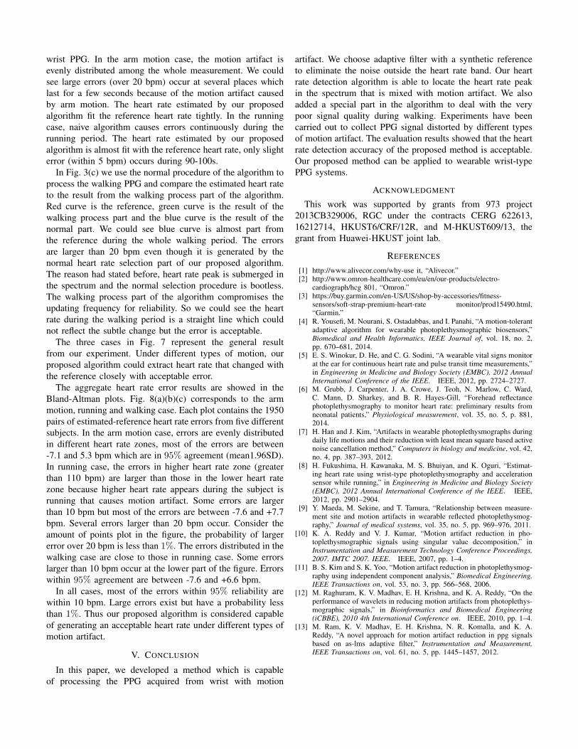
wrist PPG. In the arm motion case, the motion artifact isevenly distributed among the whole measurement. We couldsee large errors (over 20 bpm) occur at several places whichlast for a few seconds because of the motion artifact causedby arm motion. The heart rate estimated by our proposedalgorithm fit the reference heart rate tightly. In the runningcase, naive algorithm causes errors continuously during therunning period. The heart rate estimated by our proposedalgorithm is almost fit with the reference heart rate, only slighterror (within 5 bpm) occurs during 90-100s.
In Fig. 3(c) we use the normal procedure of the algorithm toprocess the walking PPG and compare the estimated heart rateto the result from the walking process part of the algorithm.Red curve is the reference, green curve is the result of thewalking process part and the blue curve is the result of thenormal part. We could see blue curve is almost part fromthe reference during the whole walking period. The errorsare larger than 20 bpm even though it is generated by thenormal heart rate selection part of our proposed algorithm.The reason had stated before, heart rate peak is submerged inthe spectrum and the normal selection procedure is bootless.The walking process part of the algorithm compromises theupdating frequency for reliability. So we could see the heartrate during the walking period is a straight line which couldnot reflect the subtle change but the error is acceptable.
The three cases in Fig. 7 represent the general resultfrom our experiment. Under different types of motion, ourproposed algorithm could extract heart rate that changed withthe reference closely with acceptable error.
The aggregate heart rate error results are showed in theBland-Altman plots. Fig. 8(a)(b)(c) corresponds to the armmotion, running and walking case. Each plot contains the 1950pairs of estimated-reference heart rate errors from five differentsubjects. In the arm motion case, errors are evenly distributedin different heart rate zones, most of the errors are between-7.1 and 5.3 bpm which are in 95% agreement (mean1.96SD).In running case, the errors in higher heart rate zone (greaterthan 110 bpm) are larger than those in the lower heart ratezone because higher heart rate appears during the subject isrunning that causes motion artifact. Some errors are largerthan 10 bpm but most of the errors are between -7.6 and +7.7bpm. Several errors larger than 20 bpm occur. Consider theamount of points plot in the figure, the probability of largererror over 20 bpm is less than 1%. The errors distributed in thewalking case are close to those in running case. Some errorslarger than 10 bpm occur at the lower part of the figure. Errorswithin 95% agreement are between -7.6 and +6.6 bpm.
In all cases, most of the errors within 95% reliability arewithin 10 bpm. Large errors exist but have a probability lessthan 1%. Thus our proposed algorithm is considered capableof generating an acceptable heart rate under different types ofmotion artifact.
V. CONCLUSION
In this paper, we developed a method which is capableof processing the PPG acquired from wrist with motion
artifact. We choose adaptive filter with a synthetic referenceto eliminate the noise outside the heart rate band. Our heartrate detection algorithm is able to locate the heart rate peakin the spectrum that is mixed with motion artifact. We alsoadded a special part in the algorithm to deal with the verypoor signal quality during walking. Experiments have beencarried out to collect PPG signal distorted by different typesof motion artifact. The evaluation results showed that the heartrate detection accuracy of the proposed method is acceptable.Our proposed method can be applied to wearable wrist-typePPG systems.
ACKNOWLEDGMENT
This work was supported by grants from 973 project2013CB329006, RGC under the contracts CERG 622613,16212714, HKUST6/CRF/12R, and M-HKUST609/13, thegrant from Huawei-HKUST joint lab.
REFERENCES
[1] http://www.alivecor.com/why-use it, “Alivecor.”[2] http://www.omron-healthcare.com/eu/en/our-products/electro-
cardiograph/hcg 801, “Omron.”[3] https://buy.garmin.com/en-US/US/shop-by-accessories/fitness-
sensors/soft-strap-premium-heart-rate monitor/prod15490.html,“Garmin.”
[4] R. Yousefi, M. Nourani, S. Ostadabbas, and I. Panahi, “A motion-tolerantadaptive algorithm for wearable photoplethysmographic biosensors,”Biomedical and Health Informatics, IEEE Journal of, vol. 18, no. 2,pp. 670–681, 2014.
[5] E. S. Winokur, D. He, and C. G. Sodini, “A wearable vital signs monitorat the ear for continuous heart rate and pulse transit time measurements,”in Engineering in Medicine and Biology Society (EMBC), 2012 AnnualInternational Conference of the IEEE. IEEE, 2012, pp. 2724–2727.
[6] M. Grubb, J. Carpenter, J. A. Crowe, J. Teoh, N. Marlow, C. Ward,C. Mann, D. Sharkey, and B. R. Hayes-Gill, “Forehead reflectancephotoplethysmography to monitor heart rate: preliminary results fromneonatal patients,” Physiological measurement, vol. 35, no. 5, p. 881,2014.
[7] H. Han and J. Kim, “Artifacts in wearable photoplethysmographs duringdaily life motions and their reduction with least mean square based activenoise cancellation method,” Computers in biology and medicine, vol. 42,no. 4, pp. 387–393, 2012.
[8] H. Fukushima, H. Kawanaka, M. S. Bhuiyan, and K. Oguri, “Estimat-ing heart rate using wrist-type photoplethysmography and accelerationsensor while running,” in Engineering in Medicine and Biology Society(EMBC), 2012 Annual International Conference of the IEEE. IEEE,2012, pp. 2901–2904.
[9] Y. Maeda, M. Sekine, and T. Tamura, “Relationship between measure-ment site and motion artifacts in wearable reflected photoplethysmog-raphy,” Journal of medical systems, vol. 35, no. 5, pp. 969–976, 2011.
[10] K. A. Reddy and V. J. Kumar, “Motion artifact reduction in pho-toplethysmographic signals using singular value decomposition,” inInstrumentation and Measurement Technology Conference Proceedings,2007. IMTC 2007. IEEE. IEEE, 2007, pp. 1–4.
[11] B. S. Kim and S. K. Yoo, “Motion artifact reduction in photoplethysmog-raphy using independent component analysis,” Biomedical Engineering,IEEE Transactions on, vol. 53, no. 3, pp. 566–568, 2006.
[12] M. Raghuram, K. V. Madhav, E. H. Krishna, and K. A. Reddy, “On theperformance of wavelets in reducing motion artifacts from photoplethys-mographic signals,” in Bioinformatics and Biomedical Engineering(iCBBE), 2010 4th International Conference on. IEEE, 2010, pp. 1–4.
[13] M. Ram, K. V. Madhav, E. H. Krishna, N. R. Komalla, and K. A.Reddy, “A novel approach for motion artifact reduction in ppg signalsbased on as-lms adaptive filter,” Instrumentation and Measurement,IEEE Transactions on, vol. 61, no. 5, pp. 1445–1457, 2012.