health technical memorandum 06-01: electrical services ... · iii preface about health technical...
TRANSCRIPT

Health Technical Memorandum 06-01 Electrical services supply and distribution2017 edition
May 2016

Health Technical Memorandum 06-01: Electrical services supply and distribution2017 edition

ii
Health Technical Memorandum 06-01: Electrical services supply and distribution (2017 Edition)
© Crown copyright 2017
You may re-use this information (not including logos) free of charge in any format or me-dium, under the terms of the Open Government Licence. To view this licence, visit www.nationalarchives. gov.uk/doc/open-government-licence/ or write to the Information Policy Team, The National Archives, Kew, London TW9 4DU, or email: [email protected].
This document is available from our website.

iii
Preface
About Health Technical MemorandaHealth Technical Memoranda (HTMs) give comprehensive advice and guidance on the design, installation and operation of specialised building and engineering technology used in the delivery of healthcare.
The focus of Health Technical Memorandum guidance remains on healthcare-specific elements of standards, policies and up-to-date established best practice. They are applicable to new and existing sites, and are for use at various stages during the whole building lifecycle (see diagram below).
Healthcare providers have a duty of care to ensure that appropriate governance arrangements are in place and are managed effectively. The Health Technical Memorandum series provides best practice engineering standards and policy to enable management of this duty of care.
It is not the intention within this suite of documents to unnecessarily repeat international or European standards, industry standards or UK Government legislation. Where appropriate, these will be referenced.
Healthcare-specific technical engineering guidance is a vital tool in the safe and efficient operation of healthcare facilities. Health Technical Memorandum guidance is the main source of specific healthcare-related guidance for estates and facilities professionals.
The core suite of nine subject areas provides access to guidance which:
• is more streamlined and accessible;
• encapsulates the latest standards and best practice in healthcare engineering, technology and sustainability;
•provides a structured reference for healthcare engineering.
DESIGN & IDENTIFYOPERATIONAL REQUIREMENTS
SPECIFICATIONS TECHNICAL & OUTPUT
PROCUREMENTCOMMISSIONING
MAINTENANCE
OPERATIONALMANAGEMENT
CONCEPTDISPOSAL
Ongoing Review
CONSTRUCTIONINSTALLATION
RE-USE

iv
Health Technical Memorandum 06-01: Electrical services supply and distribution (2017 Edition)
Structure of the Health Technical Memorandum suiteThe series contains a suite of nine core subjects:
Health Technical Memorandum 00 Policies and principles (applicable to all Health Technical Memoranda in this series)
Choice Framework for local Policy and Procedures 01 Decontamination
Health Technical Memorandum 02 Medical gases
Health Technical Memorandum 03 Heating and ventilation systems
Health Technical Memorandum 04 Water systems
Health Technical Memorandum 05 Fire safety
Health Technical Memorandum 06 Electrical services
Health Technical Memorandum 07 Environment and sustainability
Health Technical Memorandum 08 Specialist services
All Health Technical Memoranda are supported by the initial document Health Technical Memorandum 00 which embraces the management and operational policies from previous documents and explores risk management issues.
Some variation in style and structure is reflected by the topic and approach of the different review working groups.
HTM 07Environment &Sustainability
HTM 08SpecialistServices
HTM 01Decontamination
HTM 02MedicalGases
HTM 06ElectricalServices
HTM 03Heating &VentilationSystems
HTM 04WaterSystems
HTM 05FireSafety
Policies andPrinciples
INTE
RNAT
IONAL& EUROPEANSTANDARDS
INTERNATIONAL& EUROPEAN STAND
ARDS
INDUSTRY STANDARDS
INDUSTRY STA NDARDS
HEALTH SPECIFIC DOCUM ENTSH
EA
LTH
SPECIFIC
DO
CUM ENTS HEALTH
SPECIFIC
DO
CU
ME
NT
S
HTM 00

v
DH Estates and Facilities Division wishes to acknowledge the contribution made by professional bodies, engineering consultants, healthcare specialists and NHS staff who have contributed to the production of this guidance.
Other resources in the DH Estates and Facilities knowledge series
Health Building Notes
Health Building Notes give best practice guidance on the design and planning of new healthcare buildings and on the adaptation/extension of existing facilities.
They provide information to support the briefing and design processes for individual projects in the NHS building programme.
All Health Technical Memoranda should be read in conjunction with the relevant parts of the Health Building Note series.
NHS Premises Assurance Model (NHS PAM)
The NHS PAM is a tool that allows NHS organisations to better understand the efficiency, effectiveness and level of safety with which they manage their estate and how that links to patient experience. The NHS PAM has two distinct but complementary parts:
•Self-assessment questions: supporting quality and safety compliance;
•Metrics: supporting efficiency of the estate and facilities.
For further information, visit the NHS PAM website.
How to obtain publicationsHealth Technical Memoranda are available from the UK Government’s website at:
https://www.gov.uk/government/collections/health-technical-memorandum-disinfection-and-sterilization
Health Building Notes are available from the same site at:
https://www.gov.uk/government/collections/health-building-notes-core-elements

vi
Health Technical Memorandum 06-01: Electrical services supply and distribution (2017 Edition)
Executive summary
PreambleChanges in application, design and statutory requirements have led to the introduction of a new generation of equipment and new standards of reliability, hence, the need for an update to Health Technical Memorandum 06-01
This current review and update of Health Technical Memorandum 06-01 builds on the previous version of the Health Technical Memorandum by enabling users of the revised guidance to provide safer, more resilient electrical systems within their healthcare premises that support the requirements of regulators and ensure a safe environment for patients and staff.
IntroductionHealthcare premises are dependent on electrical power supplies not only to maintain a safe and comfortable environment for patients and staff, but also to give greater scope for treatment using sophisticated medical equipment at all levels of clinical and surgical care.
Interruptions in electrical power supplies to equipment can seriously disrupt the delivery of healthcare, with serious consequences for patient well-being. Healthcare organisations should therefore ensure that their electrical installation provides maximum reliability and integrity of supplies. Every effort must be made to reduce the probability of equipment failure due to loss of power.
Aims of this guidanceThe current review and update of Health Technical Memorandum 06-01 has been written to promote good practice for those responsible for the design, installation, commissioning, operation and maintenance of electrical services in healthcare premises, by:
• emphasising and addressing the need for robust governance and management, particularly through the introduction of an Electricity Safety Group and its supporting role in the provision of a resilient and safe electrical infrastructure;
• identifying key design, commissioning and maintenance requirements for referral by designers, installers, operators and management;
•providing a point of reference to legislation, standards and other guidance pertaining to electrical systems;
•providing typical distribution system layouts for a range of healthcare sites.
Main changes from the 2006 edition of Health Technical Memorandum 06-01
• This edition of Health Technical Memorandum 06-01 introduces the concept of the Electrical Safety Group in healthcare organisations (similar to the Water Safety Group in Health Technical Memorandum 04-01 on water safety). This is a multidisciplinary group responsible for ensuring that all electrical

vii
safety issues are monitored, recorded and acted on in line with the relevant legislation and guidance. Most organisations should already have an electrical health and safety committee or similar group in place to manage electrical safety. The Electrical Safety Group should take over this role, but with a more holistic remit. The Health Technical Memorandum recommends that the Group report to the responsible person at Board level and be led and chaired by a person who has appropriate management responsibility, knowledge, competence and experience. This is in keeping with the recommendations in Health Technical Memorandum 00 – ‘Policies and principles of healthcare engineering’.
• The previous edition’s clinical risk categories 1–5 and the business risk categories 1–4 (both of which are based on the type of services the healthcare facility provides/will provide) have been amended and reclassified into “risk grades” to aid clarity. The aim of the Health Technical Memorandum’s risk-grading system is to reinforce the importance of continuity of supply for the whole site and to help to assess the level of consequence of a power failure – that is, an increase in patient risk or business risk needs to have a corresponding increase in the integrity and resilience of the electrical distribution providing that service. These risk grades can then be used by designers as a basic methodology to select the most cost-effective and proportionate distribution strategy for the whole healthcare facility based on the types of clinical services the healthcare facility provides or intends to provide. It needs to be emphasised that this strategy may include high voltage (HV) and low voltage (LV) distribution networks depending on the size and complexity of the healthcare site – such is the scope of this Health Technical Memorandum. Furthermore, the clinical risk grades have been reclassified from A
(high risk) to E (low risk) and the business risk grades from I (high risk) to IV (low risk) which all in all provide a unique grading system that can be applied to, and provide for, any circumstance in healthcare.
• This edition of the Health Technical Memorandum officially confirms that the Medicines and Healthcare products Regulatory Agency’s (MHRA) guidance document MEIGaN (Medical Electrical Installation Guidance Notes) has been superseded and withdrawn by the MHRA. Electrical installation and testing in clinical areas formerly covered by MEIGaN are now covered by BS 7671. All references to MEIGaN have been removed.
•Part B on operational maintenance has now been incorporated into this design document so that Health Technical Memorandum 06-01 is a single document – there is no longer a Part A and Part B. This is considered important as construction, design and maintenance of healthcare projects are now captured in one single document.
•Guidance on emergency lighting has been updated in line with BS 5266. The most significant change is the extension of its scope to encompass “emergency safety lighting” which covers the need to protect occupants of premises who are not evacuated in a major incident or supply failure.
• The chapter on final circuits has been substantially updated to align with BS 7671.
• The chapter on electromagnetic compatibility requirements has been thoroughly reviewed and updated in line with changes to legislative requirements and standards. The chapter has also been rationalised and some of the original tables covering selected EMC criteria have been removed as these are subject

viii
Health Technical Memorandum 06-01: Electrical services supply and distribution (2017 Edition)
to constant change and dependent on test methods and other constraints.
• The chapter on wiring systems has now been removed as most of this guidance can be found in BS 7671.
•Guidance on mains extension leads has been included as a new Appendix recommending that such leads should not be used with medical electrical
equipment without a full assessment being performed by a competent person who understands the requirements given in clause 16 and the associated guidance in BS EN 60601-1.
•Guidance on the environmental effects of climate change has been provided.

ix
Acknowledgements
The Department of Health would like to thank the Steering Group for their advice and support, and all those who contributed to the consultation phase of the document.Mohammed Al-rufaie Institution of Engineering and Technology (IET)
Phil Ashcroft Department of Health (NHS Estates & Facilities Policy Division)
Michael Bernard Association of Healthcare Technology Providers for Imaging, Radiotherapy and Care (AXREM)
Ian Chell Department of Health (Emergency Preparedness and Health Protection Policy Directorate)
Eugene Conroy Institute of Healthcare Engineering and Estate Management (IHEEM)
Gerard Dean Institute of Physics and Engineering in Medicine (IPEM)
Graeme Dell British Electrotechnical and Allied Manufacturers’ Association (BEAMA)
Darren Griffiths IHEEM
Paul Harris IHEEM
Chris Holme Coordinating author
Sue Johnson Society of Radiographers
Graham Kenyon IET
Samad Khan IET
Justin McCarthy IPEM
Ken Morton Health & Safety Executive
Alan Newman Troup Bywaters + Anders
Mark Richards IHEEM
Michael Robinson ProCure22 (P22) construction procurement framework
Simon Russell NHS Wales Shared Services Partnership – Specialist Estates Services
Ian Storrar Health Facilities Scotland
David Wilson Department of Health, Northern Ireland

x
Health Technical Memorandum 06-01: Electrical services supply and distribution (2017 Edition)
Contents
Preface ...................................................................................................................................... iii
Executive summary .................................................................................................................. vi
Acknowledgements .................................................................................................................. ix
1 Scope of Health Technical Memorandum 06-01 .................................................................. 1
2 Introduction ........................................................................................................................... 7
3 Governance and risk management ....................................................................................... 9
4 Understanding the risk from loss of supply ........................................................................14
5 Initial design considerations ................................................................................................24
6 Power quality ....................................................................................................................... 32
7 Distribution strategy for resilience ...................................................................................... 35
8 Primary power – distribution centres .................................................................................. 49
9 Secondary power centres and plant ................................................................................... 58
10 Protection and switchgear ................................................................................................ 73
11 Tertiary power supplies ..................................................................................................... 85
12 Electromagnetic compatibility .......................................................................................... 98
13 Earthing .............................................................................................................................105
14 Containment and cables................................................................................................... 114
15 Final circuits ......................................................................................................................123
16 Validation and commissioning .........................................................................................136
17 Maintenance and operational management ....................................................................143
Appendix 1: Maximum interruption times to the primary supply.........................................156
Appendix 2: Sample test record sheets ...............................................................................157
Appendix 3: Drawing symbols ..............................................................................................167
Appendix 4: Use of mains extension leads (trailing sockets) with medical equipment ......168
References .............................................................................................................................170

1 Scope of Health Technical Memorandum 06-01
1
1 Scope of Health Technical Memorandum 06-01
1.1 This edition of Health Technical Memorandum 06-01 – ‘Electrical services supply and distribution’ supersedes both parts of the 2007 edition.
1.2 It provides guidance for all works associated with the electrical infrastructure within healthcare premises. The document should be used for all forms of electrical design work ranging from a new greenfield site to modifying existing electrical installations.
1.3 This document provides guidance to designers and managers of healthcare premises on how European and British Standards relating to electrical safety such as BS 7671, the Building Regulations and the Electricity at Work Regulations can be used to fulfil their duty of care in relation to the Health and Safety at Work etc. Act.
1.4 Health Technical Memorandum 00 – ‘Policies and principles of healthcare engineering’ should be read in conjunction with this document.
1.5 The requirements for medical electrical (ME) equipment and ME systems, including any testing, is outside of the scope of this document. This is covered by the Medical Devices Regulations, the BS EN 60601 series and BS EN 62353.
Note:
Any value given throughout this document may be superseded by changes in the relevant regulation/standard. Anyone using this document should confirm the validity of any value used.
Abbreviations and definitions AC: alternating current
ACB: air circuit breaker
AMD: assumed maximum demand
AP: Authorised Person
BEMS: building energy management system
BMS: building management system
BSRIA: Building Services Research and Information Association
CDM: Construction (Design and Management) [Regulations]
CENELEC: European Committee for Electrotechnical Standardization
CHP: combined heat and power
CIBSE: Chartered Institution of Building Services Engineers
CPC: circuit protective conductor
CT: current transformer
DC: direct current
DCLG: Department for Communities and Local Government
DNO: distribution network operator
Note: DNOs may change to DSOs (distribution system operators).
DRUPS: diesel rotary uninterruptible power supply

2
Health Technical Memorandum 06-01: Electrical services supply and distribution (2017 Edition)
DSR: demand side response
EBB: Equipotential bonding busbar (also known as earth reference bar (ERB)).
ELV: extra low voltage
EMC: electromagnetic compatibility
EMI: electromagnetic interference
EPO: emergency power off
ERIC: Estates Return Information Collection
ESQCR: Electricity Safety, Quality and Continuity Regulations
GSM: global system for mobile communication
HBN: Health Building Note
HRC: high rupturing capacity
HV: high voltage
HVAC: heating, ventilation and air-conditioning
IDMT: inverse definite minimum time
IEC: International Electrotechnical Commission
IET: Institution of Engineering and Technology
IGBT: Insulated-gate bipolar transistor
IMD: insulation-monitoring device
IP: ingress protection (rating)
IPS: isolated power supplies (also known as Medical IT system)
ISO: International Standards Organisation
ISS: intake substation
LBTC: logbook template customisable
LBTS: logbook template standard
LPS: lightning protection system
LV: low voltage
M&E: mechanical and electrical
MCB: miniature circuit breaker
MCC: motor control centre
MCCB: moulded-case circuit breaker
[Medical] IT: isolated terra
ME: medical electrical
MET: main earth terminal
MRI: magnetic resonance imaging
OCB: oil circuit breaker
PEI: primary electrical infrastructure
PELV: protective extra-low voltage (system)
PES: primary electrical supply
PET: positron emission tomography
PF: power factor
PFC: power-factor correction
PFI: Private Finance Initiative
PPE: personal protective equipment
PSCC: prospective short-circuit current
PV: photovoltaic
PVC: polyvinyl chloride
RCBO: residual current breaker with overcurrent
RCD: residual current device
SCADA: supervisory control and data acquisition
SELV: separated extra-low voltage (system)
SF6: sulphur hexafluoride

1 Scope of Health Technical Memorandum 06-01
3
SPD: surge protection device
SPS: secondary power supply
TETRA: trans-European trunked radio access
TLF: time fuses links may also be referred to as tlf time-lag fuses
THD: total harmonic distortion
TN: a system having one or more points of the source of energy directly earthed, the exposed conductive parts of the installation being connected to that point by protective conductors.
TN-S: a system having separate neutral and protective conductors throughout the system.
UMTS: universal mobile telecommunications service
UPS: uninterruptible power supply
VRLA: valve regulated lead acid (battery)
VT: voltage transformer
XLPE: cross-linked polyethylene
Applied part: part of a medical electrical equipment that in normal use necessarily comes into physical contact with the patient for medical electrical equipment or a medical electrical system to perform its function (source: BS 7671). See also BS EN 60601-1.
Authorising Engineer: acts as an independent professional adviser to the healthcare organisation. The Authorising Engineer should be appointed by the organisation with a brief to provide services in accordance with the HTM 06 suite of documents.
Authorised Person (HV): a person appointed to take responsibility for the management of the HV electrical system in accordance with Health Technical Memorandum 06-03 – ‘Electrical safety guidance for high voltage systems’.
Authorised Person (LV): a person appointed to take responsibility for the management of the LV electrical systems in accordance with Health Technical Memorandum 06-02 – ‘Electrical safety guidance for low voltage systems’.
Clinical area/environment: any area in a healthcare facility where there is observation and treatment of patients by one or more practitioners (see Health Building Note 00-03 – ‘Clinical and clinical support spaces’).
Designer: a person (or organisation) with the responsibility to design the electrical services in a technically correct and safe manner. The designer need not be a staff member of the healthcare organisation. See the Construction (Design and Management) Regulations for a more comprehensive definition.
Electrical Safety Group: (in a healthcare organisation) a multidisciplinary group responsible for ensuring that all electrical safety issues are monitored, recorded and acted on, in line with the relevant legislation and guidance (see Chapter 3 for a more comprehensive description).
Emergency escape lighting: that part of emergency lighting that provides illumination for the safety of people leaving a location or attempting to terminate a potentially dangerous process before doing so (source: BS 5266).
Emergency safety lighting: that part of emergency lighting that provides illumination for the safety of people staying in premises when the supply to the normal lighting fails (source: BS 5266).
Escape lighting: lighting provided for use when the supply to the normal lighting fails (source: BS 5266).
Escape route: route designated for escape to a place of safety in the event of an emergency (source: BS 5266).
Essential: any part of the electrical distribution and/or final circuit that needs, and is able, to be
4
Health Technical Memorandum 06-01: Electrical services supply and distribution (2017 Edition)
automatically transferred between either the PES or the SPS.
Extra-low voltage: normally not exceeding AC 50 V alternating current or DC 120 V ripple-free direct current whether between conductors or to earth. Lower limits apply in Medical Locations (see Table 1).
Final circuit: defined by BS 7671 as: “a circuit connected directly to current-using equipment, or to a socket-outlet or socket-outlets or other outlet points for the connection of such equipment”.
Healthcare facility/building: all buildings, infrastructure, equipment, plant, embedded systems and related items that support the delivery of healthcare and services of all types, irrespective of their ownership or operation by third parties.
Healthcare organisation: organisation that provides or intends to provide healthcare services for the purposes of the NHS.
High risk task lighting: that part of emergency lighting that provides illumination for the safety of people involved in a potentially dangerous process or situation and to enable proper shutdown procedures for the safety of the operator and other occupants of the premises (source: BS 5266).
High voltage: normally exceeding AC 1000 V or DC 1500 V (see Table 1).
Intertripping: a method in which operation of protection equipment at one end of a circuit causes a signal to be transmitted to trip a circuit breaker at the remote end of the circuit.
Life-safety system: any system incorporated into a building whose purpose is the protection and preservation of human life during an emergency or failure of a critical building system (for example, sprinkler system or fire lift).
Low voltage: normally not exceeding AC 1000 V or DC 1500 V (see Table 1).
Medical electrical (ME) equipment: electrical equipment having an applied part or transferring energy to or from the patient or detecting such energy transfer to or from the patient and which is:
•provided with not more than one connection to a particular supply mains; and
• intended by its manufacturer to be used:
– in the diagnosis, treatment, or monitoring of a patient; or
– for compensation or alleviation of disease, injury or disability.
Note:
Medical electrical equipment is not covered by this Health Technical Memorandum. The Medicines and Healthcare products Regulatory Agency (MHRA) is the government agency that is responsible for ensuring that medical equipment works and is acceptably safe.
Medical electrical system: a combination, as specified by its manufacturer, of items of equipment, at least one of which is medical electrical equipment.
Medical IT (isolated terra): IT electrical system having specific requirements for medical installations. The system will include a monitoring device to provide an alarm on loss of IMD connections, insulation failure, overload and high temperature (sometimes referred to as isolated power supply (IPS)).
Medical Location: location intended for purposes of diagnosis, treatment including cosmetic treatment, monitoring and care of patients:
Group 0. Medical Location where no applied parts are intended to be used and where discontinuity (failure) of the supply cannot cause danger to life.

1 Scope of Health Technical Memorandum 06-01
5
Group 1. Medical Location where discontinuity (failure) of the supply does not represent a threat to the safety of the patient and applied parts are intended to be used:
•externally
•invasively to any part of the body except where Group 2 applies
Group 2. Medical Location where applied parts are intended to be used, and where discontinuity (failure) of the supply can cause danger to life, in applications such as:
• intracardiac procedures
• vital treatments and surgical operations.
For a further explanation of Medical Locations Group 0, 1 and 2, see IET Guidance Note 7 – ‘Special locations’.
No-break: automatic supply available with no break.
Normal (non-essential): any part of the electrical distribution and/or final circuits connected only to the primary distribution and with no means of being connected to the essential (secondary) distribution. Note: in some distributions, manual reconfiguration may allow the normal circuits to be temporarily connected to the essential (secondary) distribution.
Open area lighting: that part of emergency lighting provided to avoid panic and provide illumination allowing people to reach a place where an escape route can be identified (source: BS 5266).
Patient connection: individual point on the applied part through which current can flow between the patient and the ME equipment in normal or single fault condition.
Patient environment: any volume in which intentional or unintentional contact can occur between patient and parts of the system or between patient and other persons touching parts of the system. This applies when the
patient’s position is predetermined; if not, all possible patient positions should be considered (see Figure 33 on page 122).
Patient: living person undergoing healthcare, therapy or diagnostic investigation (including dental and cosmetic).
Point of use: electrical distribution points where electrical equipment may be connected. This may be an accessory, for example, an isolator or socket-outlet.
Primary electrical infrastructure: comprises the primary electrical supply (PES) and electrical distribution system equipment for the facilities.
Primary electrical supply: main electricity supply generally coming from the DNO or energy supply company.
Protective extra-low voltage (system). An extra-low voltage system which is not electrically separated from earth, but which otherwise satisfies all the requirements for SELV (see Table 1).
Residual risk: a risk that has not been fully mitigated by the design process.
Secondary power supply: (in this document) any supply which supplements the PES and typically could be a generator or batteries. It could also be a CHP, solar panels or wind turbines although these should not be used solely as the secondary power supply.
Separated extra-low voltage (system): an extra-low voltage system which is electrically separated from earth and from other systems in such a way that a single fault cannot give rise to the risk of electric shock (see Table 1).
Single point of failure: a connection point (other than a point of use) where any upstream single fault will cause the loss of supply to the downstream parts of the distribution.

6
Health Technical Memorandum 06-01: Electrical services supply and distribution (2017 Edition)
Stakeholder: a person (or organisation including the Electrical Safety Group) with vested interest (not necessarily pecuniary) in the electrical services quality and provision at healthcare premises.
Standby lighting: that part of emergency lighting provided to enable normal activities to continue unchanged (source: BS 5266).
Tertiary power supply: a third supply that supplements the PES and SPS, usually in the form of a UPS or battery system.
Uninterruptible power supply (UPS): combination of convertors, switches and energy storage devices (such as batteries), constituting a power system for maintaining continuity of load power, within the limits specified for the load, in case of input power failure.
Note on the withdrawal of MEIGaN
In 2005 the Medicines and Healthcare products Regulatory Agency’s (MHRA) guidance document MEIGaN (Medical Electrical Installation Guidance Notes) was published in the form of a model specification to standardise the pre-installation requirements and standard of workmanship in electrical imaging installations.
MEIGaN partly came about as earlier versions of BS 7671 had no mention of Medical Locations. A contemporaneous CENELEC European standard HD 60364-7-710 existed, which covered electrical installations in Medical Locations, but up to 2011 was not incorporated into BS 7671.
In July 2011 the first amendment of BS 7671:2011 was published that incorporated the CENELEC harmonised document HD 60364-7-710 into the standard. Since electrical installation and testing in Medical Locations is now covered by BS 7671, MEIGaN was superseded and withdrawn by the MHRA. This status has been officially confirmed by the Health Technical Memorandum 06-01 working group in 2017.

2 Introduction
7
2 Introduction
Overview2.1 Health Technical Memorandum 06-01 provides best practice guidance on:
•design considerations for the electrical services supply and distribution within any healthcare facility;
• the operational management and maintenance of the electrical services supply and distribution within any healthcare facility.
2.2 This document has been written in a top-down format – that is, from point of supply to point of use. The design process for new builds is likely to follow a similar planning, design and construction order to that of this document.
2.3 Designers, stakeholders and the Electrical Safety Group should consider all chapters in relation to the nature of the particular project.
2.4 Throughout the document, the content of standards and guidance has been taken into account but the year of publication is not cited. This is taken as meaning the current version of the cited document when the Health Technical Memorandum was published (March 2017). Full citations are given in the References section at the end of the Health Technical Memorandum. Standards and other specification documents are continually being updated, and readers should ensure that they consult the latest editions of such documents, including any amendments issued after publication, to keep abreast of changing requirements.
2.5 Throughout this document, the voltages listed in Table 1 are used (see BS 7671 for the defined voltage bands): from the various distribution centres to the final circuits and point-of-use locations.
Non-Medical Locations Medical Locations
Extra-low voltage AC 50 V or DC 120 V ripple-free AC 25 V/DC 60 V
Separated extra-low voltage (SELV)
AC 50 V or DC 120 V ripple-free AC 25 V/DC 60 V
Protective extra-low voltage (PELV)
AC 50 V or DC 120 V ripple-free AC 25 V/DC 60 V
Low voltage Normally not exceeding AC 1000 V or DC 1500 V
High voltage Normally exceeding AC 1000 V or DC 1500 V (typically for AC this will be 11 kV, 6.6 kV or 3.3 kV).
Table 1 Voltage bands commonly used in healthcare premises

8
Health Technical Memorandum 06-01: Electrical services supply and distribution (2017 Edition)
2.6 This document has been divided into 17 chapters:
•Chapters 1 and 2 set out the structure of the Health Technical Memorandum;
•Chapter 3 details the remit and structure of the Electrical Safety Group and gives guidance on governance and risk assessments;
•Chapter 4 categorises the clinical risks and business continuity risks with regard to loss of electrical supply; it grades risks according to the dependence certain departments have on the sustainability of the electrical supply;
•Chapters 5 to 12 deal with design issues. Although this Health Technical Memorandum is written for new works and developments on a greenfield site, it should be used for all works and adaptations to the fixed wiring of any healthcare facility;
•Chapters 13 to 16 describe how the electrical services should be installed and brought together;
•Chapter 17 outlines maintenance and operational considerations. (This was previously Health Technical Memorandum 06-01 Part B of the 2007 edition.)

9
3 Governance and risk management
3 Governance and risk management
This chapter should also be read in conjunction with HTM 00 – ‘Policies and principles of healthcare engineering’.
Introduction3.1 This chapter deals with the governance and assessment of risk and the need to provide safe electrical systems in healthcare premises through the design, operation and maintenance of the electrical infrastructure to adequately protect the end-user, and in particular patients, from electrical failures. It promotes a collaborative multidisciplinary approach to both the design and operational management of the PEI and introduces the Electrical Safety Group (which includes medical professionals, clinicians, and engineering and operational staff) to the design process and overall management of electrical safety.
3.2 Most organisations should already have an electrical health and safety committee or similar group in place to manage electrical safety. The Electrical Safety Group should take over this role, but with a more holistic remit.
3.3 Healthcare organisations have an explicit duty under the Health and Safety at Work etc. Act and the Electricity at Work Regulations to assess and manage the risks posed by electrical systems on their premises. These organisations should make use of risk assessments and safe methods of operation, to ensure the safety of patients, staff and visitors with regard to electrical systems. Ensuring these elements are in place will assist the organisation to fulfil its duties in relation to the
provision of safe and robust electrical systems. A programme of audit should be in place to ensure that key policies and practices are being implemented appropriately. This will inform the organisation’s assurance framework.
3.4 Responsibility and, more specifically, the duty of care within a healthcare organisation are vested in the board of directors and its supporting structure. Though compliance with this guidance may be delegated to staff or undertaken by contractors (including PFI), accountability cannot be delegated.
Note:
Where the provision of estates and facilities services are part of a contract (including PFI), it is essential that these providers participate fully in all those aspects of estate and facilities management that can affect the safety of patients. This includes responding to specific requests from the healthcare organisation’s Electrical Safety Group, which may be in addition to relevant guidance and documentation.
The Electrical Safety Group3.5 Each healthcare organisation, through its Electrical Safety Group, should be able to demonstrate that they have suitable governance, competence and accountability arrangements in place to provide safe electrical systems in healthcare premises.
3.6 The Electrical Safety Group is a multidisciplinary group formed to assess all
10
Health Technical Memorandum 06-01: Electrical services supply and distribution (2017 Edition)
aspects of electrical safety and resilience required for the safe development and operation of healthcare premises, and it should inform the following areas:
• the design process for new healthcare premises;
• the design process for modifications to existing premises;
• commissioning;
• operational management;
•maintenance;
•decommissioning and removal of equipment.
3.7 The Electrical Safety Group, through engagement with designers, should inform the development of safe and resilient electrical distribution systems used within the healthcare environment, including redundancy and duplication as necessary (see Chapter 7). It should oversee the maintenance and operation of the system by monitoring, recording and acting on all electrical safety issues in accordance with the appropriate legislation and guidance.
3.8 The Electrical Safety Group should provide a forum in which people with a range of competencies can be brought together to share responsibility and take collective ownership for:
• identifying electrical safety issues;
• assessing risks; and
•developing and implementing control measures and incident protocols.
3.9 The Electrical Safety Group should have clearly defined roles and responsibilities, should be part of a healthcare organisation’s governance structure and should report to the designated person at Board level. It should be led and chaired by a person who has appropriate management responsibility, knowledge, competence and experience (for example, the head of estates operations).
3.10 The Group should provide assurance to the board of directors that appropriate expertise and relevant personnel are available so that policies and actions agreed by the Group are being fully implemented. This will also require assurance to the Group from designers, installers, maintainers and Authorising Engineers with regard to the safety of the electrical infrastructure.
3.11 It is important that decisions affecting the resilience, safety and integrity of electrical distribution and supply systems and associated equipment do not go ahead without being agreed by the Electrical Safety Group. In that regard, the Electrical Safety Group should ensure that sufficient, appropriate expertise and competence is always available when making such decisions.
3.12 As and when required, the local security management specialist (LSMS) should provide input. The LSMS should be consulted where information technology systems control and/or monitor the electrical systems so that a risk assessment can be undertaken. This will allow proportionate security measures to be implemented to address the threats and vulnerabilities from cyber-attacks and other network issues.
3.13 Contribution made by the Electrical Safety Group to a design, assessment or maintenance consideration should be documented and held on record.
3.14 The Electrical Safety Group may typically comprise (see Figure 1):
• estates (operations and projects) staff;
• an Authorising Engineer/independent adviser for electrical services;
• the Authorised Person(s) for electrical services;
• staff from clinical engineering (alternatively called medical equipment service unit (MESU) or electro-biomedical engineering (EBME), medical engineering, medical electronics, medical physics);

11
3 Governance and risk management
• clinicians and specialist departments (for example, radiology and/or radiotherapy);
• specialist users of medical electrical (ME) equipment (according to the clinical activity within the medical location/s under consideration);
•designers who are conversant with the design principles and the requirements of electrical systems in healthcare settings;
•personnel from the finance department with accountability for capital and revenue evaluation;
• other stakeholders as appropriate.
Note:
From time to time certain projects may require specific expert knowledge. The terms of reference should permit the chair of the Electrical Safety Group to co-opt members for the specific task reviews as appropriate.
Remit of the Electrical Safety Group3.15 The following is a typical list of tasks assigned to the Electrical Safety Group:
• to support and provide assurance to the board of directors for the safe provision of
Externaladvisers
Specialistdepartment
heads
Finance
Procurement
Fire safetyadvisers
Electricalor principalcontractors
Designers (capital and
revenue schemes)
ELECTRICAL SAFETY GROUP
The Board
AuthorisingEngineer
AP &Senior AP
AP = Authorised Person
Figure 1 The Electrical Safety Group

12
Health Technical Memorandum 06-01: Electrical services supply and distribution (2017 Edition)
electrical services for the premises/organisation;
• to undertake effective ownership of the electrical safety management of the organisation and inform the required business continuity risk assessments;
• to ensure that the electrical operational and management policy is kept under review including the risk register and other associated documentation;
• to ensure all tasks indicated by the risk assessments have been allocated and accepted;
• to ensure new builds, refurbishments, modifications and equipment are designed, installed, commissioned and maintained to the required electrical standards and the needs of the healthcare organisation;
• to ensure maintenance and monitoring procedures are in place;
• to ensure any risks pertaining to electrical safety and quality of the supply (for example, imaging equipment requirements) are addressed;
• to determine best use of available resources;
• to monitor the training and communication of relevant staff groups on electrical-related issues;
• to ensure adequate monitoring of the status of electrical safety systems and their associated alarms (for example, Medical IT/UPS systems);
• to review any proposed developments, considering whether they minimise the risk to patients – especially those treated in critical care areas – by maintaining resilience and ensuring they are compliant with all current legislation and Department of Health policy and guidance.
3.16 Detailed minutes of the group meetings should be recorded, distributed and retained in
accordance with the management policy to demonstrate good management, appropriate and timely actions and good governance.
3.17 The Electrical Safety Group should always act in an appropriate and timely manner. Individual responsibilities should not be restricted by the need to hold formal meetings.
Need for risk assessment3.18 Healthcare organisations are required to comply with the Health and Safety at Work etc. Act (HSWA), the Management of Health and Safety at Work Regulations (MHSWR), the Electricity at Work Regulations (EWR) and, where applicable, the Electricity Safety, Quality and Continuity Regulations (ESQCR). In carrying out a risk assessment process involving all key partners, the organisation can demonstrate its understanding of its duties in relation to these regulations.
3.19 The risk assessment process should identify any residual risks from the design which should be added to the healthcare organisation’s risk register. The overall assessment will enable the healthcare organisation to manage its collective ownership of risk management and hence make appropriate non-electrical and/or fixed-wiring operational and emergency contingency plans in accordance with Health Building Note 00-07 – ‘Planning for a resilient healthcare estate’ (Chapter 5 of HBN 00-07 deals with designing a resilient electricity distribution system). The risk assessment outcome should provide the necessary information to meet the requirements of the Construction (Design and Management) (CDM) Regulations.
3.20 Risk management carefully balances the approach to a design strategy with the cost/benefit relationships, where cost represents investment, business continuity and operational risk. An inappropriate level of resilience or response to a failure may compromise patient safety. See Chapter 4 for detailed guidance.

13
3 Governance and risk management
3.21 When conducting risk assessments for new and existing electrical systems, designers and the Electrical Safety Group need to be aware of the impact of climate change on electrical infrastructure (for example, environmental impacts such as flooding, water adsorption and condensation and the ambient temperature of spaces in which equipment and cables are installed). Where environmental characteristics of the installation have changed, the risk assessment needs to be reviewed accordingly. The Committee on Climate Change (2017) has compiled a report that draws together and interprets the evidence regarding current and future threats (and opportunities) for the UK posed by the impacts of climate up to the year 2100.
3.22 The risk assessment should be reviewed regularly by the Electrical Safety Group, especially when a room or space is to undergo a change in function or clinical activity.
Ownership and design3.23 The duties of the stakeholders involved in the design, assessment, operation and maintenance of a new or an existing infrastructure should ensure (so far as reasonably practicable) that all risk levels and the likelihood of an electrical failure are balanced against the consequences of such failures for each site within the organisation.
3.24 Designers, stakeholders and the Electrical Safety Group should understand and accept the intended operation, limitations and possible failure of the electrical system. Where necessary, they should implement contingency arrangements where risks of electrical failures cannot be, or are not, mitigated within or by the electrical system. These residual risks will include those inherent from the design strategy (see Chapter 7). For example, it may be agreed that an acceptable risk such as lower grade
functions may not need any embedded secondary power supply (SPS) to cover an outage/failure of the electrical system.
3.25 In accordance with the CDM Regulations, designers should ensure their designs can be maintained safely and that foreseeable risks to the health and safety of maintenance personnel are eliminated or reduced. The design should consider and facilitate equipment maintenance with minimum disruption to continuity of supply and business (see Chapter 17).
3.26 If healthcare organisations, PFI management contractors, contractors and their designers, and estate operation managers choose not to implement some of the recommendations of Health Technical Memorandum 06-01, the residual risks that arise from this approach should be recorded and managed appropriately. Any proposed departures, including any equivalent or mitigating measures to be applied, should be discussed with the relevant stakeholders including the Electrical Safety Group. Any departures – including the measures implemented – should provide a degree of safety that is not less than that obtained by compliance with this document. Any such departures should be recorded in the operating and maintenance manuals/documentation, and on the electrical installation certificate as appropriate, and should include the details and reasoning for the intended departure along with the associated measures applied. Significant residual risks should be recorded on the healthcare organisation’s risk register.
3.27 For new facilities the final design option, including any residual risks, must be agreed with, and signed off by, all stakeholders involved in the commissioning, design and operation of healthcare facilities. This will include the Electrical Safety Group on behalf of any healthcare organisation.

14
Health Technical Memorandum 06-01: Electrical services supply and distribution (2017 Edition)
4 Understanding the risk from loss of supply
Introduction4.1 An electrical system failure can occur at any point or at any time in any electrical system, regardless of the design standards employed. The design and installation of electrical systems inherently allows failure (by operation of a protective device) to minimise the risk of danger and/or risk of injury. This is true of internal PEI systems as well as the wider primary electrical supply (PES) network delivered by the distribution network operator (DNO). The effects of accidental damage and the need for maintenance and training should not be overlooked. It is essential that an appropriate level of risk management is considered and practical emergency contingency plans are always available and ready to implement. The design approach should be mindful of the need to maintain an electrical supply within specific time periods for the safety of patients and staff (see also Chapter 7). These times can be defined as a supply restored within:
• greater than 15 s;
• less than 15 s, but greater than 5 s;
• less than 5 s, but greater than 0.5 s;
• less than 0.5 s;
• no-break.
The above times need to be aligned with the distribution strategy (see Chapter 7) and final circuit configurations (see Chapter 15). (See also the IET’s Guidance Note 7 – ‘Special locations’ for further discussion on changeover times.)
Note:
It is important that healthcare organisations establish a formal working relationship with the electricity supplier. This may mean registering as a priority user. Normally this will be with a nominated client manager.
4.2 The design process should verify that single points of failure leading to loss of electricity supply are minimised by providing the appropriate level of resilience at the point of use.
4.3 All potential points of failure should be considered during the design process. Failures of the PEI system are commonly considered as a consequential effect of the failure of the incoming DNO supply, main transformer, main switchboard, etc. In all of these scenarios, it is assumed that the SPS (secondary and/or tertiary power supply) becomes available. However, failure of the PEI itself is also possible. The SPS design may be different for each type of failure.
Risk to loss of supply4.4 This Health Technical Memorandum considers risk of loss of supply in two main elements:
• clinical risk (subdivided into patient and non-patient areas); and
• non-clinical business continuity risks (subdivided into medical services and engineering services).

15
4 Understanding the risk from loss of supply
Designers and stakeholders should consult with clinical and technical staff by way of the Electrical Safety Group (especially clinical engineers, Authorising Engineers and Authorised Persons, where already appointed) to evaluate the overall risk and the measures proposed to address the perceived outcomes. Most critical within this assessment is the mobility and degree of healthcare support provided to the patient, including clinical procedures, critical care and continuity of treatment.
4.5 This chapter is intended to inform the electrical infrastructure strategy early in the design phase. Thereafter specific Medical Location groups will need to be assigned in accordance with BS 7671.
4.6 Small healthcare premises such as GP practices and health clinics/centres may have areas that fall into the lower grades of risk. Community hospitals may have departments in the low- and mid-grading of risk, but are unlikely to be in the higher grades of an acute hospital. Large acute healthcare premises and above may well have departments in all grades. There is no rule that definitively places healthcare premises in any one grade or defines one grade for a particular healthcare site.
4.7 The assessment and application of risk can be a simple or complex approach depending on size and nature of the services being provided. Each step change in the supply resilience needed will identify a response from the supply infrastructure. This may also be associated with a business continuity risk which may alter the risk being assessed. A diagrammatical representation of the process is shown in Figure 2 where a change in colour from green to red represents the movement from very low (where there is no alternative supply in the event of a power failure) to very high (where there should be several layers of support to sustain an uninterrupted supply in the event of a power failure or distribution fault) for clinical risk and similarly for business continuity risk. The graduation of the assessment should be associated with the step
changes identified either in clinical risk or business continuity risk terms, together with the distribution structure available.
Assessment process4.8 The business and clinical/patient elements described in paragraphs 4.11–4.30 are not definitive nor exhaustive but are given to guide the selection process. While the text may suggest five clinical risk grades (A–E) and four business risk grades (I–IV), it is not unreasonable to either simplify these or make them more extensive. In each case it should aid the assessment process, not stifle it. The final assessment may also be influenced by the available supply and distribution solutions.
4.9 Consideration of the categories should establish a minimum acceptable risk option at the point of treatment or care. For the purpose of this guidance, the patient levels described are not intended to be exhaustive, but rather an aid to consider the issues.
4.10 Each healthcare facility will have a mixture of grades (clinical risks and non-clinical business continuity risks) in varying ratios. The assessed higher clinical or non-clinical and business continuity risk for any particular area will determine the adopted electrical infrastructure strategy for that area. Designers, stakeholders and the Electrical Safety Group should evaluate the economics of providing different distribution strategies (see Chapter 7) for each area or of applying an appropriate distribution strategy for the highest-order risk to many or all areas.
Clinical risk4.11 Within any healthcare environment, there are wide ranges of departments with complex requirements and potential risks. The risk management process should assess each department in terms of susceptibility to risk from total (or partial) loss of the electrical supply.
4.12 The consequence of a power failure is assessed and graded against some broad

16
Health Technical Memorandum 06-01: Electrical services supply and distribution (2017 Edition)
Low risk
Grade EExample: Support services and
circulation
Grade BExample: complex treatment and
diagnostics
Grade CExample: General patient care
Grade DExample: Ambulant care
High riskGrade A
Example: Life support/complexsurgery
Risk to patient due to loss of
supply
High risk
Note: the risk grading system A–E and I–IV is only used as a guide and may differ for each project depending on risk assessment
Low risk
Risk tobusiness continuity due to loss of supply
Grade IVExample: Business support
services
Grade IIIExample: Building services
safety and security
Grade IIExample: Building services
environmental control
Grade IExample: Medical support
services
Distribution strategy (refer to Chapter 7)
LOW
HIGH
Resilience needed to support th
e risk
Fig. 10
Fig. 11
Fig. 12
Fig. 13
Fig. 14
Figure 2 Grading of risk in relation to loss of supply

17
4 Understanding the risk from loss of supply
clinical patient groups and patient care plans. This is on a scale from ambulant through to critical care. Consequence is also related to the organisation in terms of contingency arrangements, emergency preparedness and business continuity, all of which have a financial implication. There is also the operational consequence of the electrical system in terms of the operation and maintenance of the infrastructure from the point of view of both its physical construction and installation, and the managerial and technical staff structure in place to operate the electrical infrastructure.
4.13 The level of consequence of a power failure may be evaluated as increasing with the level of dependency upon the electrical supply that a patient’s care requires, and will be equally dependent on the duration and extent of the failure.
4.14 It is important to assess the dependence certain healthcare departments have on the sustainability of the electrical supply. It relates to the reliability of electrical supplies and their subsequent safety requirements. The resilience options can be ranked in time performance (seconds) to re-establishing a supply following an interruption, whether controlled or otherwise.
4.15 Within a GP practice or health centre, it may be assessed as acceptable to have single points of failure in a system, given that ambulant patients are likely to be more mobile than
patients in critical care areas and staff will be able to move away from the affected area in the event of a power failure. At the other end of the scale, for example in critical care areas or operating theatres, the consequence of a prolonged, or even a very short, power failure could result in serious health disabilities or, in the worst cases, fatality. In this instance, a more resilient infrastructure with additional levels of secondary and/or tertiary power supplies is appropriate.
4.16 While it is not intended to be absolute, this chapter should be sufficient to prompt the necessary discussion at all stages of the design process. The grading approach given is intended to demonstrate a range of patient risk from an electrical fault or loss of electrical supply.
Grading of patient risk with regard to loss of supply4.17 The measures established through discussions of risk grading may result in a very simple set of requirements; however, it may well also present a very complex range of needs and considerations. The important factor is that it should be discussed over a wide range of stakeholders and that the resultant selections are fully understood. It is the Electrical Safety Group’s responsibility to determine the range of grades to be used (see Figure 3 for examples).
RISK TO PATIENT DUE TO LOSS OF SUPPLY
E D C B ASupport services
and circulationAmbulant care General patient
care Complex treatment
and diagnosticsLife support/
complex surgery
Figure 3 Risk to patient safety due to loss of supply

18
Health Technical Memorandum 06-01: Electrical services supply and distribution (2017 Edition)
Risk grade E: typically – support services and circulation4.18 As examples, these areas may include circulation spaces, waiting areas, offices and non-patient care areas such as pharmacies (non-manufacturing) or finance departments. Consequently, loss of the electrical supply does not have an immediate effect on the clinical treatment or safety of patients (notwithstanding the requirements of escape lighting, fire alarm systems, etc. that may be provided from a local tertiary power source).
Risk grade D: typically – ambulant care 4.19 As examples, these areas may include patients in consultation (excluding examination) or general out-patient areas. Loss of supply may give rise to disruption, inconvenience and a reduced environmental quality but would not directly compromise clinical treatment and safety. The loss of electrical power to other engineering services (for example, ventilation) will not cause concern for the immediate safety of the patient or staff. There may be a business continuity risk if these areas are not connected to the SPS for failures that last for several hours (notwithstanding the requirements of escape lighting, fire alarm systems, etc. that may be provided from a local tertiary power source).
Risk grade C: typically – general patient care 4.20 In these areas, patients will generally not be connected to ME equipment over 24-hour periods. However, medical monitoring or medical test equipment may be used and connected externally to the patient’s body for a short or intermittent time (for example, electrocardiogram or ultrasound machines). Clinical treatment and patient safety will not be immediately compromised by an interruption of electrical power. However, the interruption of electrical power should be limited to less than 15 s together with other engineering services used in the support of the clinical treatment such as medical gases, hot and cold water, heating, ventilation and air-conditioning (HVAC), and communications (notwithstanding the requirements of escape lighting, fire alarm systems, etc. which may be provided from a local tertiary power source).
Risk grade B: typically – complex treatment and diagnostics 4.21 As examples, these areas may include LDRP (labour, delivery, recovery, post-partum) areas (maternity), endoscopy rooms, accident & emergency general/minors, haemodialysis areas, nuclear medicine, radiography diagnostic, magnetic resonance imaging (MRI), urology treatment areas, or therapy rooms and ultrasound. Patients may have ME equipment, medical monitoring or medical test equipment connected externally to their body for a prolonged period. Clinical treatment and patient safety may be compromised (but not endangered) by any minor interruption of electrical supply. Any interruption of the electrical supply to medical equipment should be limited to within 15 s. Consideration may be given to providing an alternative electrical supply (tertiary power supply) with a no-break or within 0.5 s subject to the range of patient treatment and resilience of equipment used. Other engineering services used in support of clinical treatment should be connected to the SPS within 15 s of any interruption of the electrical supply (notwithstanding the requirements of the escape lighting, fire alarm systems, etc. that may be provided from a local tertiary power source).
Note:
Some ME equipment may require a no-break tertiary supply if risk assessment indicates that uninterrupted functionality is essential.
Risk grade A: typically – life support or complex surgery 4.22 As examples, these areas may include operating theatre suites, critical care areas, cardiac wards, catheterising rooms, accident & emergency resuscitation units, MRI, interventional angiographic rooms, and PET and computed tomography scanner rooms. Where the disconnection of the supply represents a threat to life an alternative source (tertiary power supply) must be available within 0.5 s or as a no-break supply if critical ME equipment to be used will not continue to function without a reset after

19
4 Understanding the risk from loss of supply
a 0.5 break (see Note below). The provision of a Medical IT system will be required for socket-outlets connecting life critical equipment. However, a Medical IT system may not be required for a computed tomography, MRI or angiographic room if life support equipment is not used. The supplies for computed tomography, MRI, PET and angiographic systems may not require switching to an alternative source within 0.5 s as they are not life supporting and have a power rating that exceeds what a Medical IT system could supply. A clinical risk assessment should be performed and the equipment manufacturers consulted as some may include mandatory backup sources (for example, interventional angiographic systems with a tilting table must be able to return the table to a level CPR (cardiac pulmonary resuscitation) position in the event of a mains supply failure). A UPS may be specified to just provide backup for returning a table to CPR position, allow basic fluoroscopy for catheter removal or allow full system operation. Only a proper clinical assessment can determine the level of power supply needed, balanced against the costs of such systems. Other engineering services used in support of clinical treatment should be connected to the SPS within 15 s of any interruption of the electrical supply (notwithstanding the requirements of escape lighting, fire alarm systems, etc. which may be provided from a local tertiary power source).
Note:
Many types of ME equipment incorporate internal batteries that allow continuous uninterrupted function in the event of a mains power failure. Those that do not may default to a standby mode or may be reset to default to operational/alarm settings in the event of mains failure as short as 0.5 s, and thus require clinical staff intervention to restore appropriate settings (though it may not be immediately apparent to staff that interruption has occurred). The clinical risk of this interruption should be assessed and agreed with the Electrical Safety Group but will be completely mitigated by having no-break tertiary supplies.
4.23 Tertiary power supplies such as a UPS (see paragraphs 11.25–11.62) or a battery (within the equipment) may be considered as a method to limit the interruption of electrical supply. Standby generator(s) (see Chapter 9) may be considered as a method of limiting the interruption of electrical supply within 15 s. In areas where a patient may be at risk from both a general loss of supply and a local final-circuit fault, enhanced levels of resilience for the provision of patient therapies may be required. This may be provided by interleaved circuits at the bedhead or pendant or internal equipment configuration. Such arrangements will also assist in the ability to perform maintenance with minimal disruption.
Grading of business continuity risk with regard to loss of supply4.24 While clinical risk is the important factor in the design of PEI in healthcare premises, it does not just relate to the criticality of patients. There are numerous supporting elements and departments essential to continuity of care and business continuity.
4.25 The failure of these services should be assessed on the same basis as the clinical risk. The increasing reliance on information technology and electronic medical records is an obvious example of this, where the loss of electrical power could affect essential diagnosis of a patient or the ability to operate a clinic. Essential items of building services and plant may also necessitate the closure of departments in the event of a power failure where these services are not adequately protected by a resilient electrical system.
4.26 For the purpose of this guidance, the non-clinical and business continuity described is not intended to be exhaustive, but an aid to consider the issues (see Figure 4).
Risk grade IV: typically – business support services4.27 The business support areas are departments such as finance, stores, laundries and workshop areas. In general, an interruption

20
Health Technical Memorandum 06-01: Electrical services supply and distribution (2017 Edition)
of the electrical supply may not immediately compromise the treatment or welfare of patients. It may be appropriate to provide a single-conversion UPS (see Chapter 11) to allow certain systems such as computer applications to shut down safely. Electrical load management systems may prove useful where the interruption to the electrical supply (for these areas) is for more than 4 h (see paragraphs 9.15–9.18; notwithstanding non-patient safety measures such as emergency lighting with the provision of a tertiary power source).
Risk grade III: typically – building services life safety and security4.28 The requirements for these facilities are covered by various applicable standards and legislative documents. Typically, battery packs or single-conversion UPS systems will support such requirements. An interruption of the electrical supply could compromise the safety and welfare of patients. These facilities may be included on the load provided by the SPS, where the sum of their respective loads would only represent a very small percentage of the SPS. An understanding of the need for maintenance and the capacities of any such battery packs employed on these facilities will be required (notwithstanding the requirements of escape lighting which may be provided from a local tertiary power source).
Risk grade II: typically – building services environmental control4.29 The building services environmental control systems will include HVAC systems, hot water services, energy centres and building energy management systems. In general, an interruption of the electrical supply would represent a compromise to the treatment or welfare of patients. A single-conversion UPS should be provided to allow certain systems such as computer applications to be shut down safely. Electrical load management systems should be considered where the interruption to the electrical supply (to, say, chilled water systems) gives an unacceptable rise in the internal space temperature by internal heat gains (see paragraphs 9.15–9.18; notwithstanding the requirements of escape lighting which may be provided from a local tertiary power source).
Risk grade I: typically – medical support services4.30 The medical support areas are departments such as sterile services departments, laboratories medical records, and physiotherapy. An interruption of the electrical supply may represent a disruption to the treatment or welfare of patients. A single-conversion UPS (see Chapter 11) should be
RISK TO BUSINESS CONTINUITY DUE TO LOSS OF SUPPLY
IVBusiness support
servicesBuilding services
III
safety and security
IIBuilding services
and environmentalcontrol
IMedical support
services
Figure 4 Risk to business continuity due to loss of supply

21
4 Understanding the risk from loss of supply
provided to allow certain systems such as computer applications to be shut down safely. Electrical load management systems may prove useful where the interruption to the electrical supply (for these areas) is for long periods, say more than 2 h (see paragraphs 9.15–9.18; notwithstanding the requirements of escape lighting which may be provided from a local tertiary power source).
Electrical infrastructure system selection4.31 A number of different elements link together to form the primary and secondary electrical infrastructure system (see Figure 5). Some of the elements will be optional dependent on design strategy (see Chapter 7) and required resilience issues based on assessed risk from power failures. Dependency can also be provided at final-circuit stage (see Chapter 15). All possible configurations of the electrical infrastructure elements will have risk-mitigation strategies associated with the possibility of power failures occurring. Similarly, each element will link to other elements, and the links and interactions between them will present additional risk minimisation. The overall risk of a power failure occurring can be mitigated by the correct selection of element configurations and interconnections. Standard system and component configurations at appropriate infrastructure sections can be broadly categorised in terms of their resilience and therefore residual risks. Evaluating the cause and effect can make selection of the appropriate configurations apparent at the point of use (deepest part) of the infrastructure.
4.32 The electrical infrastructure can be considered in terms of the supply of electricity, either primary (usually the incoming supply from the DNO) or secondary (generators, combined heat and power (CHP), etc.) for on-site support in the event that the primary supply fails. Distribution within the healthcare site may further consider resilience through
backup configurations and final-circuit support (batteries) at or near the point of use.
4.33 Business continuity risk assessments evaluated by cause-and-effect models may be used to analyse the impact of electrical failures on departments that are reliant on the services provided. Within the integrated departmental model, consideration should be given to the cause and effect of electrical failures which escalate exponentially with time.
4.34 Cause-and-effect risk models of the electricity supply may be used to analyse the global electrical infrastructure from intake to point-of-use equipment. The risk evaluation should consider single electrical faults that cascade into multiple electrical faults and unrelated simultaneous multiple faults (see Chapter 7 and Chapter 10).
4.35 A distribution strategy should be developed that drives the risk of failure of an electrical supply (at the point of use) to a low or residual risk which can be agreed and managed (see Figure 2).
Resilience4.36 The resilience required to maintain essential supply in the event of not only primary failures but also secondary failures should be considered. A suitable assessment of the likelihood of concurrent failures occurring within a foreseeable period should be made, and therefore the operation and interrelationship of the system and its component parts should be fully understood. With regard to the consequence and risk, any reasonably foreseeable secondary failures should be appropriately protected against. An example here may be a standby generator failing to start (second-line fault) on a supply blackout (first-line fault).
4.37 Incoming electrical supplies may be constrained by what the DNO is able to provide or what has been assessed as cost-effective for the type of healthcare facility. The distribution strategy should maintain the

22
Health Technical Memorandum 06-01: Electrical services supply and distribution (2017 Edition)
SOURCE OF ELECTRICAL SUPPLY
PRIMARYPRIMARY ELECTRICAL SUPPLYDISTRIBUTION NETWORKOPERATOR
LV HV
LOW
VO
LTA
GE
NET
WO
RK
(S)
HIG
HVO
LTA
GE
NET
WO
RK
(S)
High Voltage Substation
Low Voltage Distribution Switch Panel
THE
ELEC
TRIC
AL
SYST
EM
Low Voltage Main (single cable) Distribution Board
Low Voltage Main
Distribution Board
Low Voltage Main (dual cables 100%
Distribution Board
TERTIARY POWER SUPPLY
UNINTERRUPTIBLEPOWER SUPPLY
MEDICAL IT
SECONDARYHEALTHCARE PREMISES
INTERNAL ELECTRICAL INFRASTRUCTURE
AlternativeEnergyPlant
CombinedHeat and
Power (CHP)
StandbyPower Plant
Alternative if provided at LV
(dual cables 50% rated) rated)
Increasing resilience with regard to patient risk
Increasing resilience with regard to business continuity risk
Figure 5 Electrical infrastructure generic flow diagram

23
4 Understanding the risk from loss of supply
required resilience level to support the internal electrical system.
4.38 An iterative design process will help stakeholders and the Electrical Safety Group to assess the distribution strategy. The process may be used to determine the location of the first single point of failure in addition to the method used to mitigate the risks on the distribution downstream of that point. The provision of tertiary supplies (UPS) on final distribution boards or the ability to manually reconfigure the distribution may be suitable risk mitigation.
4.39 The effects of electrical power failures due to faults at any level can be designed out by the robustness of the network. The distribution strategy should include adequate resilience and access space so that routine testing and maintenance can be carried out safely, without placing patients, staff and users at unnecessary risk. Such strategies may call for a redundancy in certain electrical equipment, for example generators, UPS systems and Medical IT. The provision of resilience to support maintenance is considered best practice.

24
Health Technical Memorandum 06-01: Electrical services supply and distribution (2017 Edition)
5 Initial design considerations
Regardless of the method of project procurement (design, design and build or design, build and facilities management), the design team should collaborate with the Electrical Safety Group at the initial design stage of the project and before any fundamental decisions are taken on the electrical infrastructure. Regular progress meetings should be convened by the chair of the Electrical Safety Group with all stakeholders throughout the life of the project (including the operational phase) to address any issues and record risk.
5.1 This chapter introduces the design element of the document. The intent is to assist designers, stakeholders and the Electrical Safety Group to develop the design of electrical networks for new builds, but equally it applies to modifications to existing installations. It is important to refer to the risk-assessment considerations detailed in Chapter 3 and Chapter 4 which will help to establish the overall and detailed design requirements. Some sections of this chapter should be addressed prior to or during the outline design stage, but all sections can be addressed before the detailed electrical design stage.
5.2 In accordance with the CDM Regulations, healthcare organisations should source only those designers and installers who have the skills, knowledge and experience necessary to fulfil the role that they are appointed to undertake, in a manner that secures the health and safety of any person affected by the project.
Note:
ME equipment is not the subject of this Health Technical Memorandum: equipment meeting the requirements of the BS EN 60601 series of standards is considered safe in the context of its connection to and use with patients. Non-medical equipment should not be used in a patient environment (see Definitions) unless it meets the electrical safety requirements of BS EN 60601-1 with particular regard to touch and leakage currents. Appropriate safety measures are required for electrical installations in Medical Locations, in particular with regard to resilience and to simultaneously accessible voltages arising from transient fault currents (such requirements for Group 1 and Group 2 Medical Locations are detailed in BS 7671).
5.3 While important to determine the requirements of a healthcare project in terms of overall support for lighting, power, equipment, etc., it is particularly important to identify those areas or functions that will require special consideration, for example Medical Locations of Group 0, Group 1 or Group 2. See also Chapter 15.
25
5 Initial design considerations
Note:
Healthcare organisations are required to comply with the Health and Safety at Work etc. Act (HSAW) and the Electricity at Work Regulations (EWR). In carrying out a risk assessment process involving all key partners, the organisation can demonstrate its understanding. See also the Health & Safety Executive’s (2015) guidance to the regulations (HSR25, paragraphs 62–65), particularly in the design aspects of the installation so that it can be safely maintained throughout its use.
Sources of supply5.4 All healthcare premises require an electrical connection to the PES. Electrical supplies to large healthcare premises are mainly at 11 kV (high voltage), while smaller healthcare premises may be supplied at 0.4 kV (low voltage). The supply frequency at both voltage levels will be 50 Hz. Within this Health Technical Memorandum, the connection to the PES will be referred to as the “primary source of supply”. Any embedded generating plant supported by CHP plant can supplement the main source of supply, provided appropriate measures for resilience, maintenance and safety have been included.
5.5 Many healthcare premises will require resilience of the internally distributed electrical installation, which should be provided according to the overall risk assessment (see Chapter 3). The resilience may be provided by distribution networks and embedded sources of electrical power from plant such as:
a. a secondary power supply:
(i) standby generators;
(ii) CHP systems;
b. a tertiary power supply:
(iii) rotary UPS;
(iv) static UPS;
(v) battery packs.
5.6 Adequate stocks of the fuel used by standby generators and/or CHP will need to be maintained (see Health Building Note 00-07 – ‘Resilience planning for the healthcare estate’).
5.7 UPS systems use batteries as a power source, which have a specified autonomy dependent on the connected load. A UPS and battery supplies can only be considered as a short-term measure and should be supported by a resilient primary/secondary mains network.
5.8 The PES connection may be used as the secondary source of supply where appropriate measures for capacity, resilience, maintenance and safety have been included with the embedded sources of electrical power. However, it may be less viable to provide a dual PES connection than it is to provide an additional on-site SPS (for example, standby generators).
Resilience5.9 To help achieve the higher level of resilience, healthcare premises should, if possible, be supplied by a dual PES (ideally both at 100% fully rated) arranged with either an automatic or a manual changeover system. In order to maximise the resilience of dual supply arrangements and minimise the actual single point of failure, the supplies should be diverse. Where possible, they should originate from separate DNO substations, in turn ideally fed from separate parts of the National Grid, with independent cable routes to and across the healthcare site to the substations. For larger premises two separate HV supply feeders should be considered as an additional safeguard; whether this is practicable largely depends on the local distribution system and the DNO.

26
Health Technical Memorandum 06-01: Electrical services supply and distribution (2017 Edition)
Tariff negotiations and private generation
Note:
If power is exported to the network or if power is supplied to a third party through a metered commercial contract, the requirements of the ESQCR need to be taken into account.
5.10 At an early stage of the design process, designers and stakeholders should assess the capacity of the new electrical load. Negotiations with an electrical energy supplier should be initiated at this early stage. Where the building services operator is responsible for the purchase of electrical energy, they will also be responsible for the negotiations. However, in the more usual case where the electrical energy is a pass-through cost, or where the building services operator is the healthcare organisation, the healthcare organisation will be responsible for the above negotiations.
New supplies and amendments to existing systems5.11 When submitting an application for a new electricity supply and/or undertaking redevelopment work, the designer must determine the supply capacity required or in the case of redevelopment work establish the available capacity currently under contract. The energy account bill should not be used to verify the supply capacity as errors can occur.
Note:
In 2018, excess capacity penalties will be introduced for electricity supplies where the maximum demand exceeds the available capacity level (charges will vary by region). The Electrical Safety Group should carry out regular reviews of available capacity and maximum demand levels.
5.12 The opportunities for alternative energy sources should be explored wherever practical. For example, sources such as CHP, photovoltaics (PV) or wind power will reduce the net carbon emissions and potentially provide an improved economic solution. Where alternative energy sources are used, the resilience of such plant should be considered. This may be in the form of N+1 CHP plant or suitable alternative supply from the DNO (see paragraph 7.10 for an explanation of N+1).
5.13 Healthcare organisations should consider using the BREEAM environmental assessment model and refer to Health Technical Memorandum 07-02 – ‘Encode: making energy work in healthcare’, both to help find out how their facilities and services impact on the environment and to estimate the level of environmental impact taking place.
5.14 Where the proposed alterations are for modification and/or adaptations to the internal electrical infrastructure, tariff negotiations may not be required. Nevertheless, the use of alternative power sources should still be considered to offset the increased electrical demand.
5.15 Guidance on the environmental benefits of alternative energy sources can be obtained from:
•Building Research Establishment’s Environmental Assessment (BREEAM);
•Building Services Research and Information Association (BSRIA);
•Chartered Institute of Building Services (CIBSE);
•Association for Decentralised Energy (ADE);
•Department for Environmental Food & Rural Affairs (Defra);
• The Carbon Trust.
See also Health Technical Memorandum 07-02 – ‘Encode: making energy work in healthcare’.

27
5 Initial design considerations
Demand side response framework
The Crown Commercial Service provides an income-generation opportunity for the public-sector estate via its Demand Side Response Framework. Demand side response (DSR) is a method of providing support to the National Grid during times of peak demand by turning down demand or switching to backup generation.
The framework provides sites with a revenue stream in return for responding to calls at times of system stress for periods of up to an hour at a time, several times a year. Healthcare organisations can utilise and optimise existing assets through:
•backup generation to drop total demand from the grid;
• shedding non-essential load;
•backup generation to supply to the grid.
In addition to the revenues achievable, sites benefit from more resilient asset-testing and monitoring regimes.
Healthcare organisations need to understand the design and operational implications of participating in the DSR framework and such decisions need to be discussed with the Electrical Safety Group. Issues to consider include:
•Backup generators should be designed or retrofitted for synchronous operation with the grid using G59 protection relays; the necessary permissions from the DNO should be obtained either for short-term parallel running (site load replacement) or for long-term parallel running and any generation exported where possible. This allows for seamless transfer from grid to generator power, and also simplifies regular generator testing.
•Backup generators should be designed with standard remote control interfaces for integration into DSR systems (Modbus or any other standard protocols).
•Building management systems (BMS) should be designed or retrofitted for granular and real-time control of controllable flexible assets such as HVAC and variable speed drives (not just on/off control and not just time scheduled control). A framework for BMS modifications should be agreed with the system installer/integrator to reduce future costs to the site.
•Any on-site renewables, such as solar, should have commissioning certificates issued by the meter operator and these should be kept as a matter of record.
•Main incoming meters should have pulse outputs enabled by the meter operator for integration into DSR systems.
• Installations in electrical cabinets should have some spare space on DIN railing to facilitate future installation of control and metering equipment, and around cable installations for installation of current transformers (CTs).
•Where possible, Wi-Fi connectivity (with secure passwords) should be provided near flexible assets for integration with future control and monitoring equipment.
• The potential for increased generator operating and maintenance costs.

28
Health Technical Memorandum 06-01: Electrical services supply and distribution (2017 Edition)
Supply voltages5.16 The DNO will deliver the PES at the customer’s intake terminals at a declared voltage in accordance with the requirements of the ESQCR. Each healthcare facility will have an electrical supply up to the following voltages:
• 11 kV – large acute hospital, typical floor area greater than 8500 m2;
• 11 kV/0.4 kV – medium-sized acute hospital, typical floor area 5500 m2 to 8500 m2;
• 0.4 kV three-phase and neutral – general/community hospitals, health centres, large off-site clinics, off-site administrative buildings, stores and decontamination facilities;
• 230 V single-phase and neutral – GP and dental practices, small off-site clinics.
The types of healthcare facility in the above list are for illustration and are not definitive. For voltage tolerances in the above list, see BS 7671 and the ESQCR.
5.17 Some larger sites may have multiple feeds (at the intake point) with an internal distribution network (see Chapters 7–9). In such cases, the declared voltage will be up to either 11 kV or 0.4 kV. Such connection arrangements provide an improved resilience of supply.
5.18 Some healthcare sites, particularly older sites that have expanded over a number of years, may have multiple intake points (which may not all be at the same supply voltage). The various intake points should be consolidated to a single or multiple feeds at a common point. Such arrangements will provide economies with tariff and standing charges.
5.19 The DNO may arrange with the healthcare facility (under a wayleave agreement) to have the DNO electrical equipment, including transformer, on-site. This arrangement is frequently used in rural areas where the healthcare facility is some distance from the nearest DNO substation. In such cases, the
DNO’s electrical equipment will be at a higher voltage (up to 11 kV) to that supplied at the healthcare site’s intake terminals (0.4 kV).
Design of installations for growth and change5.20 Changes in medical technology and healthcare practice have had an effect on the requirements for electrical power in healthcare. Examples include:
• increase in diagnostic imaging (computed tomography and MRI) and patient monitoring at the bed;
• electronic patient records and patient entertainment systems – although these have a very low electrical power requirement, such systems require a significant increase in containment and space (see also Health Technical Memorandum 08-03 – ‘Bedhead services’).
5.21 Alterations to existing installations, unless planned and allowed for during the original construction, can be costly, particularly when structural changes are involved.
5.22 Healthcare premises are frequently remodelled within the economic life of an electrical installation. Designers, stakeholders and the Electrical Safety Group should identify means of remodelling the electrical distribution and determine to what extent any flexibility for remodelling should be incorporated within the initial design. This should include the provision of structural or architectural allowances such as safe adequate access or risers.
5.23 Each electrical distribution board should include space for retrofitting of switches, protective devices, etc. This space should be in accordance with the projected clinical strategy.
5.24 The designers and the Electrical Safety Group should evaluate, by risk assessment, the degree of remodelling and natural expansion that will be incorporated into the initial

29
5 Initial design considerations
installation. The risk assessment should reflect both clinical and commercial risks.
5.25 This allowance for growth and remodelling should be incorporated into the adopted distribution strategy (see Chapter 7).
Assessment of existing electrical systems5.26 The electrical load allowance should be agreed with the client and be based on the site’s clinical strategy and the practical limitations of what the site can accommodate.
5.27 Designers, in association with the Electrical Safety Group, should make a reasonable assessment of any existing electrical services that are to be modified or connected to as part of the proposed works. It is not acceptable to rely on “rules of thumb”, and the designer should assess accurately the anticipated load. For existing sites, the building-site records should provide details of the existing electrical systems, periodic test results (including fault levels), applied diversity, load profile and schematic drawings of the electrical system and/or network. Examination of the settings on all adjustable protection devices will identify the extent of any tolerance within the grading and discrimination of such protective devices.
Greenfield site5.28 Where the proposed work is a new building site, the assessment of existing electrical systems may be limited to an understanding of the DNO’s infrastructure in the area. This knowledge will help in determining the cost associated with any reinforcements (for example, additional transformers and cabling infrastructure).
New build on existing site5.29 Where the proposed work is a new building on an existing site or an extension of an existing facility, the assessment of existing electrical systems will determine the extent of
any spare capacity at the proposed connection point. This knowledge will help to determine the practicalities and cost associated with any reinforcements of switchgear, protection devices and cables.
New equipment on existing site5.30 Where the proposed work is limited to the installation of new equipment or the modifications of distribution and final circuits, the power requirements and an understanding of the existing distribution (including final circuits) will determine the most appropriate connection point and any reinforcements of switchgear, protection devices and cables.
Load profile5.31 Designers and the Electrical Safety Group should understand the electrical profile of the healthcare facility at an early stage. This will prove invaluable in assessing the viability of any secondary and/or tertiary power (for example, CHP plant). Where the healthcare facility is an existing site, electrical demand data records should be available. Data will be available from:
• any in-house energy management tools;
• the meter operator;
• the electricity supplier;
• the local DNO.
Assessing electrical energy consumption
5.32 Estates Return Information Collection (ERIC) data enables the analysis of estates data such as energy consumption. Statistics taken from the healthcare organisation’s annual ERIC returns are a good basis for assessment and can be used to indicate its performance relative to its peers. Most importantly, ERIC should be treated as the standard first step when analysing such data.
5.33 In addition, Health Technical Memorandum 07-02 – ‘Encode: making energy work in healthcare’ presents results based on actual energy use according to buildings’ display

30
Health Technical Memorandum 06-01: Electrical services supply and distribution (2017 Edition)
energy certificates (DECs) which can be used as benchmarking for different types of healthcare buildings. It compares its findings to CIBSE TM46’s benchmarking figures on electricity consumption.
5.34 Also, CIBSE’s TM22 – ‘Energy assessment and reporting method’ uses a benchmarking system for comparing and assessing building energy consumption. Designers can use the software tool accompanying TM22 at the briefing stage of a project to discuss a healthcare facility’s likely energy profile and use that information to set realistic performance targets. Modules in TM22 enable electricity load profiles to be reviewed regularly.
Diversity factors5.35 The electrical diversity factor is the ratio of instantaneous power to the total installed power. Diversity factors can be applied to each element of the electrical service (for example, the lighting load or low-power load) or to a whole department. Where the healthcare site is large and has multiple substations, the diversity factors can be calculated for each individual substation. It should be clear that the diversity factor for a particular service (for example, lighting) may differ during the day and year, while the diversity of, say, the chiller plant may have a different cycle. Similarly, the diversity variation for one department (for example, radiology) may be higher on weekday mornings than in the afternoon, while the accident & emergency department may peak in the early evenings.
5.36 The above variations in actual diversity will reflect the true load profile.
5.37 Designers should assess the actual diversity factors for each service and department to make an assessment of the site-wide normalised diversity. This figure can then be applied to the total installed power and the allowance for growth to determine the electrical capacity of the DNO’s connection.
Consideration for EMC requirements5.38 Refer to Chapter 12 for further guidance.
Access for maintenance5.39 In order to comply with the CDM Regulations, designers need to give due account for safe, adequate access and maintenance at a very early stage of the design, irrespective of the size, complexity and extent of the proposed installation.
5.40 Electrical services should not compromise the space and access routes for other services such as HVAC, mechanical and drainage as it is imperative that maintenance tasks should be able to be carried out with the minimum disruption to continuity of supply and business.
5.41 The following documents provide additional general information:
•Health Technical Memorandum 00 – ‘Policies and principles of healthcare engineering’;
•BSRIA’s (2011) BG 9 – ‘Rules of Thumb – guidelines for building services’;
• the BS EN 547 series;
•manufacturers’ operating and maintenance manuals.
Commissioning procedures5.42 Designers, in association with the Electrical Safety Group, should consider how the installation will be commissioned and how the required test measurements should be made. This will include the inspection of services that may be hidden at the time of handover. It will also include the implications of any phased occupation (see Chapter 16 for more information). See also Chapter 4 of Health Technical Memorandum 00 for guidance on validation of engineering installations.
5.43 The design team should make an application to connect the new works to the

31
5 Initial design considerations
DNO or healthcare site prior to doing so. At this point, the installation should be suitably safe and ready to be energised.
Connection to the DNO5.44 Where the new installation will be connected directly to the DNO’s network (PES), the DNO will be entitled to conduct a range of tests to be satisfied that the installation is safe for energising and that any fault currents which may arise are cleared before connecting to the DNO’s network.
5.45 In cases where the new installation includes embedded generation sources (including CHP or PV cells), the DNO will need to understand the methods used to clear any faults from the internal energy sources so that they are not reflected on to the DNO’s network.
5.46 For greenfield sites, it may be necessary to coordinate the activities of the DNO, meter operator and energy supplier before a connection can be completed.
5.47 The DNO will reserve the right not to connect a new installation where the installation fails to comply with its criteria.
Connection to the healthcare site’s network5.48 Where the new installation will be connected into part of the healthcare site’s existing network, the healthcare facility will be entitled to conduct a range of tests to be
satisfied that the installation is safe for energising and that any fault currents which may arise are cleared before reflecting on to the remaining part of the healthcare site’s network.
5.49 The healthcare organisation’s Authorised Person may reserve the right not to support connection of a new installation where the installation is not considered safe or compromises the distribution strategy of any other part of the electrical network.
5.50 At an early stage of the design (or if appropriate, procurement planning), the designer should assess the power requirement and subsequently make a request for a suitable supply.
Supply from the DNO5.51 Where the new supply will be direct from the DNO, the designer should contact the DNO for the appropriate forms. The cost of the supply will reflect the level of infrastructure reinforcement.
Supply from internal connection point5.52 Where the new supply will be connected to part of the healthcare facility’s existing internal distribution, the designer should liaise with the site engineer to determine the most appropriate connection point and the required method and degree of reinforcement of the internal distribution.

32
Health Technical Memorandum 06-01: Electrical services supply and distribution (2017 Edition)
6 Power quality
6.1 The quality of the electrical supply is the responsibility of the DNO, which will comply with the requirements of the ESQCR. However, the use of electrical energy within healthcare premises can affect the quality of the internal distribution in terms of power factor and harmonics. The normal supply frequency is 50 Hz with a tolerance of ±1%. The nature of the electrical equipment used throughout the site can create secondary frequencies that cause significant disturbances to the internal distribution and the supply. The majority of the secondary frequencies, known as harmonics, are generated from short surge currents and transient currents arising from non-linear electrical loads such as switch-mode power supplies, rotating machinery and variable speed drives found in a wide range of electrical and electronic equipment.
6.2 The designer should make suitable provision for power-factor/harmonic issues to maintain regulatory compliance, for example:
•Healthcare premises have numerous switch-mode power supplies and inherently high inductive electrical loads and, unless corrected, the power factor will be poor, requiring large transformers, cables and high-energy cost.
•Where large quantities of IT equipment are present (for example, data centres and human resources departments), significant harmonics may be generated. These result in large peak currents and high crest factors.
•Where variable speed drives are present, significant odd harmonics in the order of 5th, 7th, 9th, etc. may be generated.
•Where diagnostic equipment is installed (for example, MRI and catheter laboratories), large transient currents are introduced which will impose stresses on the electrical infrastructure.
6.3 Consideration should be given to fixed monitoring and reporting of power quality and harmonics.
6.4 At the design stage of new builds and refurbishments, it is difficult to determine the requirements for power-factor correction and harmonic filters. Therefore, the designer should provide evidence with regard to what funding, physical space allowance and electrical connection points (with associated current transformers) are needed for all power-factor correction and harmonic filters. The Electrical Safety Group should engage with the contractor/designer to evaluate how this is incorporated within the contract. This evaluation should include a post-completion survey and potential installation works.
Power-factor correction6.5 The usual method of correcting a low power factor uses capacitive reactance to oppose the inductive reactance. Using capacitor banks with automatic step changes will ensure that the net reactance does not produce a leading power factor. There are three basic locations for power-factor correction equipment. Consideration should be given to using detuned capacitors where harmonics may be an issue.

33
6 Power quality
Located at the intake point6.6 Power-factor correction can be installed at the main distribution intake point, in which case the entire electrical system will be corrected. The power-factor correction equipment should be automatically disconnected if the primary supply is interrupted; if used in conjunction with the standby generator plant (or CHP plant), it should be adjusted to suit the generator (or CHP plant) manufacturer’s recommendations. Where the only power-factor correction equipment is located at the intake, the appropriate cable sizes for the higher currents should be used on the distribution cables.
Located at main distribution boards6.7 Power-factor correction can be installed at the main distribution board, in which case only the outgoing circuits will be corrected. The advantage of power-factor correction units installed at main distribution boards is that several inductive loads can be corrected with one common unit. This will save on the capital cost and space required. Where the power-factor correction equipment is located at the intake and main distribution boards, the appropriate cable sizes for the higher currents should be used on the distribution cables. Similarly, the rating of the main distribution board and protective equipment may need oversizing.
Located on the electrical equipment6.8 Where individual pieces of equipment generate a high inductive reactance such as large motors and chillers, it is advisable to install the power-factor correction direct to the motor. This arrangement has the advantage of reducing the voltage drop on the motor supply cable(s) and hence smaller distribution cables can be used.
6.9 Power-factor correction equipment may generate harmonic currents as well as allowing the downstream harmonics to pass through. Therefore, consideration should be given to the use of detuning inductors and capacitors within the power-factor correction equipment.
6.10 Power-factor correction equipment requires natural ventilation to remove the small amount of heat it generates. Further information on the amount of natural ventilation should be available from the manufacturer.
Harmonics6.11 Even-order harmonic frequencies are self-negating and do not cause a real disturbance to the electrical distribution. Odd-order harmonics with zero rotation effect, known as “TripleN” harmonic frequencies (3rd-, 9th- and 15th-order), and odd-order harmonics (5th, 7th and 11th) can cause significant disturbances leading to high currents and voltages, and overheating of cables and equipment, particularly transformers.
6.12 Electrical systems should comply with the Energy Networks Association’s Engineering Recommendations G.5/4, which limits the reflected total harmonic distortion (THD) at the point of common coupling. For voltages up to 0.4 kV, the THD is 5%, whereas up to 11 kV the THD is 4%. Designers should evaluate the sources of harmonic disturbances within the healthcare site’s electrical network and the methods to mitigate the effects. Harmonics can be controlled by the use of harmonic filters (active or passive). The use of oversized neutral conductors will carry the harmonic current back to the transformer, which then should be sized for such currents and heat. Consideration should also be given to the use of low-noise earth conductors for power supplies to items such as computer server and hub rooms. A single-phase third-harmonic current on a balanced three-phase circuit can produce high currents which flow within the neutral conductor. If the harmonic currents reach the distribution transformer, they will be reflected into the primary delta winding and circulate. The unchecked harmonic current in the primary winding of a distribution transformer will be dissipated as unwanted heat and noise.
6.13 The network analysis of harmonic currents propagated within the electrical systems should be made and communicated to the supplier of

34
Health Technical Memorandum 06-01: Electrical services supply and distribution (2017 Edition)
any standby generator. The generator design will need to reflect the anticipated harmonic currents. Harmonic currents not allowed for within the generator design may cause excessive heating, high torque loads and vibration within the generator while running. Only active harmonic filters or isolating passive harmonic filters should be used while the generator is online (see paragraph 6.16).
6.14 The electrical load of a typical healthcare facility with many modern medical facilities and support services may have non-linear loads (propagating harmonic disturbances) at 40% of the overall load. Unless the harmonics are controlled and eliminated downstream from the transformer’s primary winding, the transformer may need to be derated by the “factor-K method” (as defined in BS EN 50464-3), which may typically be 70% of the transformer nameplate kVA rating to avoid transformer damage.
6.15 Alternative methods may include using oversized neutral conductors, using separate transformers for linear circuits and using inductive loads or preferably harmonic filters. Active or passive filters can be located at the following three locations (paragraphs 6.16–6.18)depending on the severity of the disturbance.
Located at the intake point6.16 Harmonic filters can be installed at the main distribution intake point, in which case the entire electrical system will be corrected. Any passive harmonic filters should be automatically disconnected when any standby generator plant is supplying the load.
Note:
The intake point means the HV/LV substation’s LV switchboard. Alternatively, where the site has an internal HV network, the intake point means each such substation’s LV distribution board.
Located at main distribution boards6.17 Harmonic filters may be installed at the main distribution board, in which case only the outgoing circuits will be corrected. The advantage of harmonic filters installed at main distribution boards is that several sources of harmonic inductive loads can be corrected with one common unit. This will minimise the harmonic disturbance reflected on the main distribution cables and save on the capital cost and space required.
Located on the electrical equipment6.18 Where an individual piece of equipment generates a high transient current or voltage from a switch-mode power supply, it is advisable to install active harmonic filters direct to the equipment. This arrangement has the advantage of reducing the harmonic disturbances on the final distribution cables.
Transient voltages and currents6.19 Transient over-voltages or surges are also caused by lightning strikes and electrical switching events. Further details on lightning strikes and surge protection devices (SPDs) can be found in paragraphs 13.33–13.61.

35
7 Distribution strategy for resilience
7 Distribution strategy for resilience
7.1 It can be reasonably assumed that the highest distributed voltage in any healthcare facility will be up to 11 kV. DNO connections to healthcare facilities may be at elevated voltages such as 33 kV, but it is considered that such voltages are not distributed within the healthcare site. Where healthcare facilities do have a DNO connection at voltages above 11 kV, the strategy for such connections (and if appropriate, distribution) should follow the distribution philosophy described in this chapter. This Health Technical Memorandum only considers any electrical energy used at low voltage as a three-phase or single-phase connection. It also recognises that some electrical energy used in healthcare premises will be at SELV or PELV, but is only concerned with the fixed wiring at low voltage. In a similar way, electrical energy used at high voltage, for some large vapour compression chillers for example, is acknowledged.
7.2 When designing the strategy for the electrical network(s), it is essential to take a holistic approach. The electrical system may include HV and LV distribution networks, or just LV distribution networks, depending on the size of the site.
7.3 The topology of the LV network(s) can provide the most resilient service at the point of use. The cost of such security of supply will be compromised if the HV system is not equally resilient. Best practice is achieved when the distribution strategy places the first single point of failure as close to the final circuits as practical to satisfy the critical nature of the healthcare facility.
7.4 The required system resilience can be achieved in two basic ways: first, by having an alternative power supply and, second, by having alternative distribution cables and/or routes; both may be engaged by automatic changeover with manual bypass.
7.5 Standby generators can be connected at the intake point or may be connected at specific LV switchboards. While this chapter describes the resilience provided by generators, it does not describe the starting or control methods, which can be found in Chapter 9.
7.6 The resilience can be enhanced at the final distribution board with the use of tertiary power supplies such as a UPS (see Chapter 11). Alternatively, the resilience can be enhanced by the use of medical equipment such as intravenous pumps which incorporate internal battery packs. Further guidance on alternative supplies can be found in Chapter 9. This section deals with the strategy and design of the fixed distribution network to achieve the desired resilience.
7.7 To determine the required level of resilience for an electrical distribution system, all stakeholders, including the Electrical Safety Group, and designers should contribute to the risk assessment as described in Chapter 3. The level of risk mitigation provided by the level of resilience of the design should be agreed by all stakeholders including (depending on the project procurement route) project commissioners, the Electrical Safety Group, contractors and design consultants.
36
Health Technical Memorandum 06-01: Electrical services supply and distribution (2017 Edition)
7.8 The available electrical supply rating should be verified with the DNO. It is important to work with the DNO to establish the most resilient position possible (see also HBN 00-07 – ‘Planning for a resilient healthcare estate’). Most DNOs will provide between 500 kVA and 800 kVA as a single LV (0.4 kV) connection. Supply ratings between 750 kVA and 12 MVA should be supplied at high voltage (up to 11 kV). Where a healthcare facility has an assumed maximum demand (AMD) greater than 12 MVA, the DNO connection should be at 33 kV or above. Clearly, where the healthcare facility has an AMD of less than 500 kVA, the internal electrical infrastructure will only be at low voltage; other AMDs will require an HV and LV internal infrastructure.
7.9 When establishing the PES to be provided by the DNO it is important to understand the distribution network from which any proposed supply may be provided. Direct supplies from a 33 kV/11 kV substation may be more resilient than a single supply from an 11 kV local network. Where two 11 kV supplies are provided, it is more beneficial for them to be from different networks.
Design for resilience7.10 Throughout this Health Technical Memorandum (and in common parlance) resilience is expressed in terms of “N+1”. This Health Technical Memorandum considers N+1 to mean the normal total requirement plus one resilient unit. For example, where the electrical demand is 1000 kVA, two transformers at 1000 kVA carrying 50% load would satisfy the N+1 definition.
Essential/non-essential supplies7.11 There is an increasing reliance on electrical supplies to meet a healthcare organisation’s operational needs.
7.12 The need for more resilient supplies increases the demand on the SPS. Electrical demand in the healthcare sector is typically growing at a rate of between 3% and 6% year
on year. A suitable philosophy should be agreed with the organisation’s Electrical Safety Group to reflect this growth before sizing the SPS and distribution strategy.
7.13 A risk-orientated approach should be adopted, and the different requirements established, to assign appropriate SPS provision. For higher grade risk areas, there should be 100% load provision.
7.14 The provision of two separate systems, each of smaller power capacity, should be balanced against having one larger power system in terms of economics and reliability in emergencies. The availability of the distribution and final circuits for testing, validation and upgrading of systems should also be taken into consideration.
7.15 In systems that employ a separate secondary supply, thought should be given to the space needed for separate feeders, independent risers and stand-alone distribution board enclosures so as to reinforce the system resilience. This will help to ensure that a local failure will not compromise the entire system.
7.16 Even when two separate systems are provided (primary and secondary), an emergency coupling should be normally locked open between them. This allows the standby generator to be connected to both systems if necessary; for example, during a prolonged outage, some normally non-supported services may become essential, such as catering and laundry. In addition, with the coupling it is possible to provide a larger test load.
7.17 Where primary and secondary circuits are installed, diverse cable routes should be provided. The possibility of a single cable fault or single incident damaging both circuit cables should be minimised as much as possible.

37
7 Distribution strategy for resilience
Note:
Busbar distribution systems can add to the overall risk due to single point of failure compared with multiple cable circuits, and their use needs to be accepted by the Electrical Safety Group.
7.18 In areas where there are many primary and secondary circuits, where space allows, separate cable trays should be used for the routing of cables to minimise the risk of multiple damage. Where possible, power and protection/control cables should be segregated to minimise the risk of loss of protection/control due to consequential damage in the event of a power-cable failure.
7.19 Consideration should be given to the requirements for fire-protected cables or cable routes (see also Health Technical Memorandum 05-02 (Firecode) – ‘Fire safety in the design of healthcare premises’).
Supply connections7.20 In electrical supplies to large healthcare premises (in electrical terms this means greater than 2 MVA), a general arrangement with two PES connections should be adopted, arranged with either an autochangeover or manual-selection. Two supplies with diverse routes may be considered an economic strategy to maximise the resilience and minimise the actual single point of failure. They should originate, if possible, from separate DNO substations, ideally fed from separate parts of the National Grid, with independent cable routes to the healthcare site’s substations.
Risk of transformer failures7.21 The only moving part of a transformer is the tap-changing mechanism, which may be discounted when considering transformer reliability. As a result, transformer reliability can be as high as 99.999% (or 0.001% unreliable), which could mean 5.25 minutes of unavailability per year. However, the issue is the time to repair
or replace a faulty transformer. Distribution strategies that have two transformers, both 100% rated, supplied from a common primary supply, but have their secondary distribution linked by a normally open switch, would provide a transformer system resilience of N+1. While both transformers are on duty, they would share the load of the distribution network, approximately 50% being provided by each transformer. In the event of failure or for maintenance opportunities, either of the transformers can carry the full load. Such arrangements are shown for the intake substation (ISS) in Figure 9 on page 41. Transformers connected in parallel or operating transformers on no load are not recommended.
Risk of generator failures7.22 Generators have many moving parts requiring lubrication, cooling and control. The standby generator controls are electronic and electromechanical devices used to modulate the output in response to the demand inputs. Standby generators should be maintained in an operational readiness state in order to provide their principal function of the SPS. Generator reliability may be of the order of 99.95% (or 0.05% unreliable), which equates to 4.5 h of unavailability per year. The majority of generator failures are a result of the generator not starting or occur during the first five minutes after starting.
7.23 Distribution strategies that have two standby generators (each rated at full load) with a common point of coupling at the distribution network would provide generator system resilience of N+1. Three standby generators, similarly connected, all rated at 50% of the connected design load, would also provide a generator system resilience of N+1. Opportunities for standby generator and associated primary/secondary maintenance are improved, as well as improved continuity of supply following a generator outage (while the sets are on line). Such arrangements are shown in Figure 13 on page 46.

38
Health Technical Memorandum 06-01: Electrical services supply and distribution (2017 Edition)
Other reasons for failure of electricity supply7.24 The following list provides further reasons for failure of the main internal electrical distribution systems, all of which are minimised by adopting the guidance within this Health Technical Memorandum and the guidance given in Health Technical Memorandum 06-02 – ‘Electrical safety guidance for low voltage systems’ and Health Technical Memorandum 06-03 – ‘Electrical safety guidance for high voltage systems’:
• cable faults within the private distribution system;
• inappropriate grading of protection devices;
•poorly designed network with common points of failure;
• reliance on one form of SPS;
• accidental isolation;
•poor maintenance on the LV system, in particular changeover systems;
• lack of familiarity with the operation of switchgear under the control of the healthcare organisation.
Site distribution system – HV7.25 Healthcare premises with an AMD greater than 800 kVA will require an internal HV network. There are two basic forms: radial networks (for AMDs up to, say, 3.5 MVA) and ring networks (for AMDs above 3.5 MVA).
7.26 The following simplified schematics are provided to show the main HV supply arrangements. They are arranged generally in order of resilience from low to high, but their selection as a design solution will be dependent on the supply arrangement available from the DNO, the type of healthcare facility, and the level of assessed risk with regard to end-users. Where typical HV distribution arrangements are shown connected to the LV distribution, these are included only to assist in the understanding of
the LV arrangements. LV distribution arrangements are considered more fully in paragraphs 7.42–7.68. This section does not describe the control of any standby generator system (see Chapter 9 for details).
HV network resilience – one radial circuit with one substation only7.27 In Figure 6, a single HV supply from the DNO feeds on to the healthcare site’s HV-switchboard part of the substation. This would typically be up to, say, 1500 kVA.
7.28 This type of distribution strategy is appropriate for a small-to-medium-sized hospital. As there is only one primary source of supply, this system creates a single point of failure right through to the LV distribution switchboard(s). Designers and the Electrical Safety Group should consider the benefits afforded by the additional resilience that may be required, dependent on the assessed risks (see Chapter 3 and Chapter 4).
7.29 The resilience of the HV supply of Figure 6 may be enhanced by including a secondary source of supply at the intake, as a second DNO connection, or an LV standby generator at the LV switchpanel (see Figure 12 and Figure 13). Generators at the LV switchpanels add resilience to the internal distribution and allow maintenance of the incoming HV board.
Substation ISS
DNO or healthcare premisesconnection
Figure 6 HV network – one radial circuit, one substation
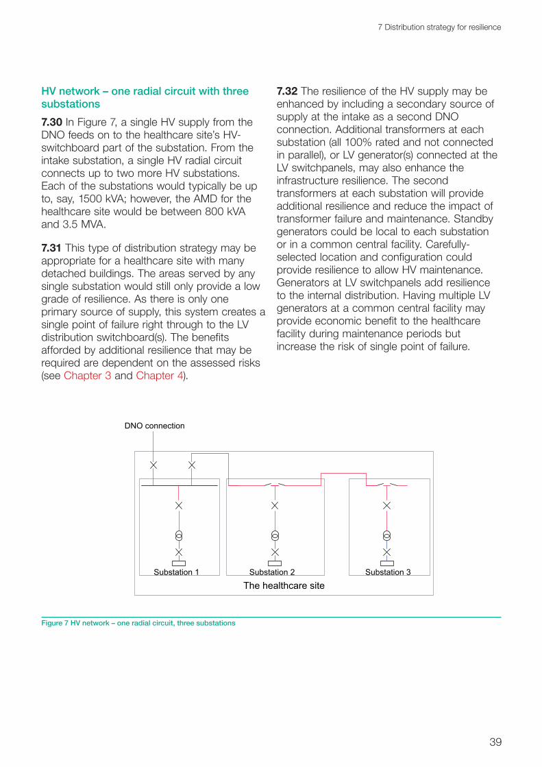
39
7 Distribution strategy for resilience
HV network – one radial circuit with three substations7.30 In Figure 7, a single HV supply from the DNO feeds on to the healthcare site’s HV-switchboard part of the substation. From the intake substation, a single HV radial circuit connects up to two more HV substations. Each of the substations would typically be up to, say, 1500 kVA; however, the AMD for the healthcare site would be between 800 kVA and 3.5 MVA.
7.31 This type of distribution strategy may be appropriate for a healthcare site with many detached buildings. The areas served by any single substation would still only provide a low grade of resilience. As there is only one primary source of supply, this system creates a single point of failure right through to the LV distribution switchboard(s). The benefits afforded by additional resilience that may be required are dependent on the assessed risks (see Chapter 3 and Chapter 4).
7.32 The resilience of the HV supply may be enhanced by including a secondary source of supply at the intake as a second DNO connection. Additional transformers at each substation (all 100% rated and not connected in parallel), or LV generator(s) connected at the LV switchpanels, may also enhance the infrastructure resilience. The second transformers at each substation will provide additional resilience and reduce the impact of transformer failure and maintenance. Standby generators could be local to each substation or in a common central facility. Carefully-selected location and configuration could provide resilience to allow HV maintenance. Generators at LV switchpanels add resilience to the internal distribution. Having multiple LV generators at a common central facility may provide economic benefit to the healthcare facility during maintenance periods but increase the risk of single point of failure.
Substation 3Substation 2Substation 1
The healthcare site
DNO connection
Figure 7 HV network – one radial circuit, three substations

40
Health Technical Memorandum 06-01: Electrical services supply and distribution (2017 Edition)
HV network – three radial circuits each with one substation7.33 In Figure 8, a single HV supply from the DNO feeds on to the healthcare site’s HV-switchboard part of the substation. From the intake substation, three HV radial circuits, each with one substation, are connected. Each of the substations would typically be up to 1500 kVA; however, the AMD for the healthcare site would be between 800 kVA and 3.5 MVA. This distribution network is an enhancement of that in Figure 7 above, as failure of any part of the internal HV electrical infrastructure (other than the main ISS) will affect a smaller area. The two 100%-rated transformers (not operated in parallel) of substation 2 will provide improved transformer and switchgear maintenance opportunities for that area.
7.34 This type of distribution strategy may be appropriate for a healthcare premises with many detached buildings. As there is only a
primary source of supply, this system creates a single point of failure right through to the LV distribution switchboard(s).
7.35 The resilience of the HV supply of Figure 8 may be enhanced by including a secondary source of supply at the intake as a second DNO connection. Standby LV generator(s) connected at the LV switchpanels will enhance the infrastructure resilience and facilitate improved transformer maintenance opportunities. Standby generators could be local to each substation or in a common central facility, depending on the spread of the site. A standby generator at a LV switchpanel adds resilience to the internal distribution. Having multiple LV generators at a common central facility may provide economic benefit to the healthcare facility during maintenance periods but may increase the risk of single point of failure.
Substation 1 Substation 3
Substation ISS
The healthcare site
Substation 2
DNO or site connection
Figure 8 HV network – three radial circuits each with one substation

41
7 Distribution strategy for resilience
HV ring network – ring with four substations7.36 In Figure 9, a single HV supply from the DNO feeds on to the healthcare site’s HV-switchboard part of the substation. From the intake substation one HV ring circuit connects to all other internal HV substations (which may be more than the four shown here). Each of the substations would typically be up to, say, 1500 kVA; however, the AMD for the healthcare site would be greater than, say, 3.5 MVA. This distribution network is an enhancement of that in paragraphs 7.33–7.35, as failure of any part of the internal HV ring electrical infrastructure will affect a smaller area. Following a ring distribution fault, the manual or automatic operation (where the switchgear has suitable
controls) of network ring switch positions will restore the inherent resilience.
7.37 The HV ring network of Figure 9 indicates the four basic types of HV substation: single and dual ring main units, single or dual circuit breakers. The intake substation should consist of circuit breakers, and all field substations should have a common switch type. See Chapter 10 for additional details of HV protection and switchgear details.
7.38 This type of distribution strategy may be appropriate for a large acute hospital with several other support facilities on the same site. The areas served by the ISS and substation 3 may include high grade risk
Substation ISS
Substation 4Substation 3Substation 2
The healthcare site
PES DNO connection
Figure 9 HV ring network – ring with four substations
42
Health Technical Memorandum 06-01: Electrical services supply and distribution (2017 Edition)
assessments and the areas served by substation 2 and substation 4 may include lesser grade risk assessments. As there is only one primary source of supply, this system creates a single point of failure right through to the LV distribution switchboard(s).
7.39 The resilience of the HV supply of Figure 9 may be enhanced by including a secondary source of supply at the intake, as a second and carefully positioned DNO connection. Additional transformers at each substation (all 100% rated and not connected in parallel), or standby LV generator(s) connected at the LV switchpanels, may also enhance the infrastructure resilience. The transformers at each substation may provide resilience and assist in transformer failure and/or maintenance. Standby generators could be local to each substation or in a common central facility, depending on the spread of the site. The generator at a LV switchpanel would add resilience to the internal distribution. Having multiple LV standby generators at a common central facility may provide economic benefit to the healthcare facility during maintenance periods but may increase the risk of single point of failure.
7.40 The resilience of the HV ring network can also be enhanced if the ring normally operates in a “closed ring” control. Electrical faults may then be isolated to a discrete section of the ring (typically one substation leg or between two substations) and hence not affect the supply to any part of the healthcare site. An alternative level of resilience may be available by the introduction of a switch control monitoring and management system to the HV ring switch. Such a system can automatically reconfigure the HV network open position of the closed ring, and hence restore power to all areas, well within a few minutes (see Chapter 10).
7.41 The resilience of the HV ring network can be enhanced if one substation is equipped with a different type of switchgear from that used in the other substations. In the event of a failure mode requiring an operational restriction
on HV switchgear, this will enable remedial action to be taken without a complete network shutdown.
Primary and secondary LV distribution systems7.42 All LV distributions should be configured as TN systems.
Note:
The ESQCR prohibits consumers from combining neutral and earth in a single conductor within the installation.
7.43 The following simplified schematics are provided to show the main LV distribution arrangements. They are arranged in order of resilience from low to high, but their selection as a design solution will be dependent on the supply arrangement available from the DNO, the type of healthcare facility, and the level of assessed risk with regard to end-users.
7.44 A method of fire protection should be considered for essential distribution circuits and associated distribution board equipment. Essential circuits associated with life-safety systems should be either fire-rated or fire-protected.
7.45 Single-line representation is used in the diagrams for single- and three-phase distribution. Where typical HV distribution arrangements are shown connected to the LV distribution, these are included only to assist in the understanding of the LV arrangements. HV distribution arrangements are considered more fully in paragraphs 7.25–7.41.

43
7 Distribution strategy for resilience
Primary LV supply – single-cable distribution7.46 Figure 10 shows the simplest form of LV infrastructure with a primary supply only, direct either from the DNO or from a single HV transformer arrangement, feeding a single-cable LV distribution network. The transformer switchgear and main cables should be rated to take the AMD and an allowance for growth (see paragraphs 5.20–5.25).
7.47 The first single point of failure will be the connection point (to the DNO healthcare site’s transformer). A LV infrastructure of this kind is appropriate for low grade risk (see paragraphs 4.11–4.23). This infrastructure does not provide for inconvenience-free maintenance opportunities. Therefore, the infrastructure lends itself to healthcare premises that do not operate 24 hours a day/7 days a week (24/7) facilities, and hence give opportunities for maintenance windows that do not affect business continuity.
7.48 Enhancing the infrastructure resilience and adding a facility to connect a mobile generator plant at the intake may improve the maintenance opportunities and business continuity. Alternatively, a single-conversion UPS (see Chapter 11) may be connected to dedicated equipment such as computer systems or network hub cabinets.
7.49 An assessment of the potential for expansion and/or remodelling of the healthcare premises should be made to understand how the LV distribution of Figure 10 could accommodate such adaptations.
7.50 This simple arrangement may be appropriate for GP practices, health centres and office accommodation, dependent on the assessed level of risk posed by a failure.
Substation ISS
Risk grade E/D
Risk grade E/D
Risk grade E/D
Note:LV incoming supply – no resilience available except a point could be provided to connect a mobile generator if needed to support planned maintenance or a scheduled supply interruption.
Figure 10 Primary LV supply – single-cable distribution

44
Health Technical Memorandum 06-01: Electrical services supply and distribution (2017 Edition)
Primary and partial secondary LV supply – introduces secondary supply support to part of network7.51 This form of LV infrastructure (see Figure 11) has a primary supply connected directly to either the DNO or the healthcare site’s transformer and a secondary supply connected at an internal LV switchboard. The transformer, switchgear and main cables should be rated to take the AMD and an allowance for growth (see paragraphs 5.20–5.25). However, the standby generator is rated only for the specifically supported part of the healthcare site’s electrical demand.
7.52 The first single point of failure will be the connection point (to the DNO site’s transformer) for the single-cable circuits. However, the dual distribution circuits have a single point of failure much nearer the point of use. This infrastructure does not fully provide for inconvenience-free maintenance opportunities to all areas.
Therefore, the infrastructure lends itself to healthcare premises that have part 24/7 facilities and part non-24/7 facilities. Enhancing the infrastructure resilience and adding additional standby generator units to the essential circuits may improve the maintenance opportunities and business continuity. Alternatively, a manual load management system coupled with the facility to interconnect the essential and non-essential circuit (via cables or a manual bus coupler) may offer a similar increased resilience (see Chapter 10).
7.53 An assessment of the potential for expansion and/or remodelling the healthcare premises should be made to understand how the LV distribution of Figure 11 could accommodate such adaptations.
Substation ISS
Risk grade C
Risk grade D
Risk grade D
G1
Note:LV incoming supply – minimal resilience achieved by grade D areas. Grade C area has partial secondary support from a generator with the ability (by manual switching) to be fully supported if a suitably rated generator is available.
Figure 11 Primary and partial secondary LV supply – single cable with partial primary/secondary distribution

45
7 Distribution strategy for resilience
Primary and fully-rated secondary LV supply – single and dual (100% rated) cable distribution7.54 This form of LV infrastructure (see Figure 12) has a primary supply connected directly to either the DNO or the healthcare site’s transformer, and an SPS also connected at the intake LV switchboard. The transformer, standby generator, switchgear and main cables should all be rated to take the full AMD and an allowance for growth (see paragraphs 5.20–5.25).
7.55 The first single point of failure will be at the main LV switchboard for the single-cable circuits and at the point of use for the dual cable circuits. An LV infrastructure of this kind is appropriate for assessed risk, including business risk, that cannot sustain a prolonged loss of primary supply. This infrastructure may provide for inconvenience-free maintenance opportunities in the dual-cable distribution. However, the same opportunities do not exist in the single-cable distribution areas, where the infrastructure resilience is only achieved by the standby generator subject to the operating demand.
There is no further distribution resilience with the single distribution cables and/or switchgear. The single-cable circuit infrastructure lends itself to that part of the healthcare premises that do not operate 24/7, but the dual-cable circuit infrastructure lends itself to those which do operate 24/7.
7.56 Enhancing the infrastructure resilience may be achieved by adding a tertiary power source at the point of final distribution. A single-conversion UPS may be connected to dedicated final circuits of the single-cable distribution. Adding a suitably-situated additional standby generator unit may improve the maintenance opportunities and business continuity.
7.57 An assessment of the potential for expansion and/or remodelling the healthcare premises should be made, to understand how the LV distribution could accommodate such adaptations. This arrangement may be appropriate for a general acute or large acute hospital with additional support services, dependent on the assessed level of risk posed by a failure.
G1
From healthcare site’s network or DNO connection
Risk grade CRisk grade D
Risk grade E
Substation on a healthcare site
Load control
Note:HV incoming supply – improved resilience from an HV supply for grade D and E areas. Grade C area has improved secondary support from a generator and autochangeover to full area support from a suitably rated generator. Grade D and E areas may also be supported from an SPS by manual extension and load control.
Figure 12 Primary and secondary LV supply – single and dual (100% rated) cable distribution

46
Health Technical Memorandum 06-01: Electrical services supply and distribution (2017 Edition)
Dual-primary and dual-secondary LV supply – with single-cable and dual-cable infrastructure (autochange) distribution7.58 The LV infrastructure shown in Figure 13 has a dual-primary supply connected directly to either the DNO or the healthcare site’s transformer and a dual-secondary power supply also connected at the intake LV
switchboard. The transformer, standby generator, switchgear and main cables should all be rated to take the AMD and an allowance for growth.
7.59 The first single point of failure will be at the point of use for the dual-cable distribution circuits. An LV infrastructure of this kind is appropriate for clinical risk grades C/B
G2
HV network
Risk grade C/B
Risk grade D
Risk grade D
CHP
G1
Areas served from substation
Substation on ahealthcare site
Note:HV ring main supply – further improved resilience from an HV supply to all areas together with resilient secondary supplies to all areas. Dual distribution supply to grade C/B area, normally each providing 50% load but 100% load rated for resilience.
LV distribution may also be configured as shown in Figure 14.
Figure 13 Dual-primary and dual-secondary LV supply – with single-cable and dual-cable infrastructure (autochange) distribution

47
7 Distribution strategy for resilience
(see Chapter 4). This infrastructure may provide for inconvenience-free maintenance opportunities. However, the same opportunities do not exist in the grade D risk areas, where there is no resilience with the distribution cables and/or switchgear.
7.60 Enhancing the infrastructure resilience may be achieved by adding a tertiary power source. A single-conversion UPS (see Chapter 11) may be connected to dedicated final circuits of the single-cable distribution infrastructure. Enhancing the dual infrastructure resilience and adding additional standby generator units may improve the maintenance opportunities and business continuity for the higher risk areas.
7.61 An assessment should be made of the potential for expansion and/or remodelling of the healthcare premises and how the LV distribution of Figures 12 and 13 could accommodate such adaptations. This arrangement may be appropriate for general acute or large acute hospitals with additional support services, dependent on the assessed level of risk posed by failures.
7.62 Figure 13 shows a potential connection point for a CHP plant. The schematic only provides one of many potential electrical connections for the CHP plant. Designers should assess the ideal CHP connection based on the opportunity to “black start” the CHP sets, and to synchronise the CHP with the PES supply and/or standby generator supply.
7.63 In reality, the CHP location may be driven by the thermal and environmental requirements rather than the electrical connection. For example, locating the CHP plant close to the boiler plant may provide a more beneficial connection for the reclaimed heat energy into the boiler return pipework. In addition, the CHP engine exhaust can be ducted alongside the boiler flues.
Dual-primary and dual HV secondary supply – with single-cable and dual-interleaved (autochange) and local UPS-supported distribution7.64 The LV infrastructure illustrated in Figure 14 has a dual-primary supply connected to a healthcare site’s HV switchboard which supplies two healthcare site transformers, and two SPS dual distributed cables connected directly to the HV switchboard. The transformer, standby generators (which may be LV and connected through step-up transformers), switchgear and main cables should all be rated to take the full assumed maximum demand and an allowance for growth (see paragraphs 5.20–5.25).
7.65 Having multiple HV/LV generators at a common central facility may provide economic benefit to the healthcare facility during maintenance periods but increase the risk of single point of failure.
7.66 The first single point of failure will be at the point of use for all circuits. An LV infrastructure of this kind is appropriate for high-risk clinical areas and has the added installed resilience of tertiary power supplies, double-conversion UPS and Medical IT systems. This infrastructure may provide for inconvenience-free maintenance opportunities in all areas, particularly when the final circuits are interleaved (see Chapter 15).
7.67 The potential for expansion and/or remodelling of the healthcare premises should be assessed in terms of how the LV distribution could accommodate such adaptations. The arrangement may be appropriate for a large acute hospital with additional support services, dependent on the assessed level of risk posed by a failure.
7.68 Many large healthcare premises will have a mixture of clinical risk areas (see paragraphs 4.11–4.23) and consequently may require an overall distribution strategy based on a mixture of the above examples. Designs with a single distribution strategy, best suited to the highest category of clinical risk across the whole healthcare site, are less complex and easier to control. The design strategy principles promoted by this Health Technical Memorandum achieve the best opportunities for flexibility and remodelling.

48
Health Technical Memorandum 06-01: Electrical services supply and distribution (2017 Edition)
Substation ISS
Risk grade B and A
Risk grade D
Risk grade D
G1 G2
HV generator substation
The healthcare site
The
heal
thca
re s
ite n
etw
ork
Service 1 Service 2
MedicalIT
UPS
DNO DNO
MedicalIT
UPS
Risk grade C/B
Areas served from substation
Generators may also be configured as LV generators with step up to HV
Note:Dual distribution to grade C risk areas and above with interleaved supply to risk grade B and A areas where final circuits are also supported by a UPS and Medical IT system.
Figure 14 Dual-primary and dual HV secondary supply – with single-cable and dual-interleaved (autochange) and local UPS-supported distribution

49
8 Primary power – distribution centres
8 Primary power – distribution centres
Substations, transformers and switchrooms8.1 Guidance on the number, type and location of any HV substations incorporated within the site’s electrical distribution is given in Chapter 7. This chapter provides guidance on the design of HV substations and main LV switchrooms owned by the healthcare organisation (or nominated agent). This Health Technical Memorandum does not govern substations that are owned by the external DNO, usually limited to the main intake point. However, designers and stakeholders, including the Electrical Safety Group, should liaise with the external DNO to ensure that such substations have suitable access and space provision. HV substations and LV switchrooms that include an integral space for the external DNO’s HV or LV cables and equipment may be appropriate, providing that adequate control and areas of responsibility can be clearly defined. For the purpose of this guidance, HV substations are deemed to be the total area of the HV switchgear and transformer enclosure.
Location8.2 External and internal locations can be used for HV substations and LV switchrooms. External HV substations can be located at ground or roof level. Internal HV substations and LV switchrooms can be located on any level; however, access and egress (see paragraphs 8.21–8.23) and where applicable DNO requirements need to be considered when designing locations.
8.3 HV substation and LV switchroom locations should be subject to an environmental assessment particularly with regard to flooding, drainage-system overflows, ventilation, etc.
8.4 The potential for harmonic interference, fault level and zone of protection should be addressed when locating transformers. The transformer should be located within 1 to 3 m from the respective HV switchgear, and as close as possible to the respective LV switchgear.
8.5 HV substations located in close proximity to the principal LV switchboard afford the best opportunity to regulate earth faults between the two items
8.6 External HV switchgear and transformers should be located away from any live vegetation by a minimum distance of 3 m. The clear zone includes the area above and below the substation. Low-maintenance grassed areas are an acceptable derogation from this requirement.
8.7 The location of main HV and LV switchgear should be in accordance with the recommendations given in Table 1 of Health Technical Memorandum 05-02 (Firecode) – ‘Fire safety in the design of healthcare premises’ and the adjacencies described within the document.
8.8 HV substations and LV switchrooms should not be located under bulk water (or any other fluid) storage areas or wet distribution systems.

50
Health Technical Memorandum 06-01: Electrical services supply and distribution (2017 Edition)
Construction8.9 External HV substations within enclosed compounds should be constructed on well-drained surfaces (with catchments slightly greater than the volume of oil, for any spilled oil, as appropriate). The electrical equipment should be placed beyond the reach of personnel stood external to the substation and/or transformer compound.
8.10 External HV substations can be constructed from brick, concrete or glass-reinforced plastic, or be of steel fabrication to the same enclosure standard of an internal HV substation.
8.11 Where external substations have a metallic enclosure construction or the substation is open and surrounded by a metallic fence, see BS 7430 for earthing arrangements. Reference should also be made to BS EN 62271-202.
8.12 The construction of internal HV substations should be sufficiently robust to contain the effects of an electrical explosion emanating from within, and should provide suitable acoustic attenuation. External HV substations should be fitted with a pressure-relief facility to allow controlled venting in the event of an electrical explosion.
8.13 HV substations should be constructed to minimise the effect of electrical interference.
8.14 Walls, floors and ceilings forming the HV substation should be constructed from fire-resisting materials and must comply with the Department for Communities and Local Government’s (DCLG) Approved Document Part B on fire safety.
8.15 Construction of internal HV substations, transformer rooms and LV switchrooms should include adequate fire precautions to satisfy the recommendations given in Health Technical Memorandum 05-02 (Firecode).
8.16 Where a fluid-filled transformer is installed, a bund area should be provided sufficient to
hold more than the capacity of fluid within the transformer.
8.17 Internal walls should have a suitable finish to reduce dust formation and facilitate cleaning. Floors should have a non-slip dust-reducing finish.
8.18 HV substations and LV switchrooms should be constructed to prevent the ingress of water or flooding. Specific precautions are required where cables enter from external areas (including subterranean).
8.19 HV and LV switchroom doors should open outwards and have a total clear opening to allow replacement of switchgear and transformers
8.20 Minimising and mitigating against the effects of heat gain should be assessed when considering the construction and location of substations.
Access and egress8.21 External substations should have good access for road vehicles to facilitate plant replacement and maintenance. External substations should be so arranged and constructed as to prevent unauthorised access. Gates or other purpose-made openings should provide adequate clearance for plant replacement, inclusive of any manual handling equipment and personnel. There should be a minimum of two sets of gates, on opposite sides, to provide suitable escape routes. For external substations, additional gates will be required to ensure that the maximum travel distance to a safe haven is no greater than 9 m.
8.22 Internal substations and main LV switchrooms should have good access for road vehicles to facilitate plant replacement and maintenance. This will generally mean that they are located on the perimeter of the ground floor or in separated dedicated buildings. Where internal substations are not at ground-floor level, a clear method statement describing the arrangements for plant replacement and maintenance should be provided, without the

51
8 Primary power – distribution centres
need to dismantle individual switches, circuit breakers or transformers. Internal substations should be so arranged and constructed to prevent unauthorised access (see Health Technical Memoranda 06-02 and 06-03). Door openings should provide adequate clearance for plant replacement, inclusive of any manual handling equipment and personnel. There should be a minimum of two sets of door openings connecting directly to a safe haven, on opposite sides, to provide suitable escape routes. Additional door openings will be required to ensure that the maximum travel distance to a safe haven is no greater than 9 m.
8.23 The access to any HV substation, including the HV side of a transformer, should be arranged so as to prevent unauthorised access (see Health Technical Memorandum 06-03).
Layout
See also BS EN 61936-1.
8.24 The layout of HV substations will depend partially on the distribution strategy employed (see Chapter 7). Internal HV substations should have level room height of 1 m greater than the equipment height. Maintenance space on the sides, rear and front of the equipment should be at least 1 m plus the equipment depth required for withdrawal. The requirement may be derogated where the HV equipment is combined on to a switchboard or close-coupled with a transformer, although the design clearance requirements for safe internal arc-venting of the switchgear should be maintained. However, it is essential to ensure that all cables and equipment can be serviced and replaced without any modification to the room. Where the distribution strategy has dual supplies and multiple transformers per substation, a physical fire barrier between each section may improve the fire precautions and inherent system resilience. Where the HV equipment includes a withdrawable section (see Chapter 10), the depth of the equipment should be added to the clear maintenance space. The maintenance
space will include the headroom above all HV equipment and transformer. The headroom should be a minimum of 1 m measured between the soffit (and the underside of any drop beam) and the highest point of the equipment. The minimum clearances required for maintenance/replacement of HV switchgear components should also be maintained. Designers should liaise with the structural engineer for the coordination of services within the HV substation. Risk assessments should be undertaken to determine the amount of space to be set aside for future expansion and flexibility (see Chapter 3).
8.25 HV cables used for the supply and interconnection of HV equipment and transformers (including the LV secondary side cables) are best laid in a cable trench or duct. Suitably-installed busbars would be an acceptable derogation from this requirement. Cable trenches or ducts should be of adequate cross-section to facilitate the pulling-in and replacement of additional cables. Cables should be positively fixed to the sidewalls of cable trenches and ducts, and so arranged as to prevent the need for cable crossover.
8.26 HV equipment should sit partially over the cable trench to facilitate final cable connection. Such arrangements will require adequate sidewall construction and edge-wall protection.
8.27 HV substations should not be used for any purpose other than HV equipment and cables. The room should not be used for the storage of other items at any time. The room should not be used as a conduit for other engineering services, including drainage.
8.28 Cable trenches and ducts should have a natural drainage fall, and be sealed to prevent the ingress of water, where they pass through walls. Similarly, the cable trench/duct should provide the same fire integrity as the wall, where the trench/duct passes under the wall, that is, preventing ingress of gas or foam fire-extinguishing fluids.

52
Health Technical Memorandum 06-01: Electrical services supply and distribution (2017 Edition)
8.29 LV switchrooms should not be used for any purpose other than LV equipment and cables. The room should not be used for the storage of other items at any time. The room should not be used as a conduit for other engineering services, including drainage.
8.30 LV switchrooms should have a clear maintenance space of a minimum 0.8 m on all sides of equipment contained therein. The room height should be even, and at least 1 m greater than the equipment height. It is essential that all cables and equipment can be serviced and replaced without modification to the room. Where the distribution strategy has dual supplies and/or interleaved distribution, a physical fire barrier between each section may improve the fire precautions and inherent system resilience. Where the LV switchgear includes a withdrawable section (see Chapter 10), the depth of the switchgear should be added to the clear maintenance space. A risk assessment to determine the amount of space set aside for future expansion (see Chapter 3) should be undertaken. LV switchrooms should not be used for any purpose other than LV switchgear, controls and cables. The room should not be used for the storage of other items at any time except for equipment used for switching and testing. The room should not be used as a conduit for other engineering services, including drainage.
Fire precautions8.31 HV substation and LV switchroom construction must satisfy the requirements of DCLG’s Approved Document Part B on fire safety. Designers should comply with the medical adjacencies as defined in Table 1 of Health Technical Memorandum 05-02 (Firecode) – ‘Fire safety in the design of healthcare premises’. Designers and the Electrical Safety Group (in conjunction with the healthcare premises’ Fire Safety Adviser, the local authority’s fire officer and a specialist fire consultant) should carry out a full risk assessment, to address the form of suitable firefighting equipment and precautions.
8.32 The risk of a fire should also be determined by the effect of an electrical fault causing explosions. Such electrical faults will include those that can be assumed to happen and those that may arise from unauthorised interference. The fire-extinguishing equipment should include an audible and visual alarm system within the substation area, immediately outside the substation, and within a suitable 24-hour staffed location (telephonist).
8.33 Automatic fire-extinguishing equipment should be provided where internally-located transformers contain flammable material (for example, mineral oil). Specialist fire engineers should undertake the design of such firefighting equipment.
8.34 Automatic fire-extinguishing equipment of the halon or CO2 type should be replaced and not considered for new installations.
Note:
As halon is associated with the depletion of the ozone layer, the decommissioning of halon systems must be undertaken in a controlled manner and the halon collected and disposed of by a certified agent.
8.35 Transformers suitably rated for external location and located in the open air of a compound may not require any specific fire precautions or extinguishing equipment.
8.36 Where a HV substation is part of a ring network or main intake substation with dual supplies, consideration may be given to having the two network incomers in two rooms separated by a suitably fire-rated partition wall, the two sections being linked by a fully-rated cable.
Environmental requirements8.37 External open-air HV substations do not require any environmental requirements. Lighting should be provided for security and possible emergency working. Maintenance staff

53
8 Primary power – distribution centres
should be protected from bad weather during emergency working. External HV substations located in an enclosure should have the same environmental conditions as an internal HV substation.
8.38 Internal HV substations and LV switchrooms should be illuminated by maintained lighting to an average level of 200 lux at floor level. The illumination should not cast shadows on any instrumentation and working surfaces of the equipment. Escape lighting should provide an average of 15 lux at floor level for 3 h, and be supported by a secondary source.
8.39 It is important to control both the temperature and relative humidity in HV enclosures, as high levels of relative humidity are known to promote the development of partial discharge. Transformers typically radiate between 1.5% and 2% of their rating as heat, which should be removed by means of natural ventilation, where possible, to maintain environmental conditions. Where natural ventilation is considered unable to meet requirements, supply and extract ventilation
connected directly to an external wall and arranged to prevent short-circuiting should be installed. Room temperatures should be maintained above 10°C and within the maximum permissible equipment operating temperature. Any low-level background heating required should be thermostatically-controlled.
8.40 Natural ventilation may be achieved by a crossflow of air as illustrated in Figure 15 with specific consideration also being given to the impact of ambient temperatures due to climate change. The total area of an opening may be calculated from a typical formula, for example:
0.90S1 = S = (0.18P/(√H))
where
S and S1 = lower and upper total opening areas, respectively (m2)
P = sum of the no-load and full-load losses of the transformer (kW)
H = height difference between the centre lines of the two openings (m).
S
S1
H
Figure 15 Air flow through a transformer room

54
Health Technical Memorandum 06-01: Electrical services supply and distribution (2017 Edition)
8.41 The above formula should be corrected for ambient room temperatures above 20°C and/or altitudes above 1000 m.
8.42 Where natural ventilation cannot be secured, designers may wish to consider forced ventilation with an airflow rate (q) calculated by:
q = 0.081P (for fluid transformers)
q = 0.05P (for dry-type cast-resin transformers)
where
P = total losses of the transformer (kW).
8.43 An alternative to the crossflow arrangement may be to have the external wall fully louvred such that there is a 40%–60% free-air area. Provisions for adequate ventilation rates of transformer rooms are a significant factor in determining the location of internal transformer rooms.
Equipment and notices provided8.44 HV substations and main LV switchrooms should include the following equipment as a minimum set (see Health Technical Memoranda 06-02 and 06-03):
• safety posters as identified by Health Technical Memoranda 06-02 and 06-03 as appropriate, including first aid/electric shock treatment;
• up-to-date single-line diagrams as identified by Health Technical Memoranda 06-02 and 06-03;
• a mimic board – intake substation only (including where appropriate key locks, keys, safety key boxes, safety signs and site logbook);
• cabinet containing key locks, keys and site logbook
• a sign positively identifying the LV earthing system;
• a battery charger (for the instruments and power-driven switches, including trip circuits) and on-load test facility;
• storage space for maintenance tools and test equipment;
• appropriate fixed lifting equipment.
8.45 Consideration may be given to the provision of LV or SELV socket-outlets, derived from a resilient routed secondary source (standby generator) for the use of competent persons (see Health Technical Memorandum 06-02).
8.46 Note that a sign positively identifying the LV earthing system should also be located at each final distribution board, motor control centre and similar locations.

55
9 Secondary power centres and plant
9 Secondary power centres and plant
For earthing requirement standards, see BS 7430 and BS EN 50522.
9.1 This chapter deals with secondary power supplies (SPSs) and their connection to the electrical infrastructure.
9.2 The use and operating configurations of CHP plant are comparable with standby generators; but with CHP, the thermal energy produced can be harnessed. It is for this reason that CHP plant may not be considered as the only SPS. The electrical connection and operating arrangements for CHP plant are discussed in this Health Technical Memorandum only as a generator operating in parallel with the PES. Installation with PV and/or wind turbines as an SPS is set out in the Energy Network Association’s Engineering Recommendations G.83/1.
9.3 Opportunities exist to allow secondary electrical power supplies to become the prime power source and the PES to become the SPS. Designers, in consultation with the Electrical Safety Group, should consider the overall risk strategy for such arrangements. Non-technical issues can influence the operating viability of alternative energies such as CHP, including reduced carbon emissions and the rejection of excess thermal energy. The design process should evaluate the resilience of generating plant (such as CHP plant) with multiple sets running at below full duty, or having spare capacity on the DNO connection to the PES.
9.4 The chapter concentrates on standby generators supporting either single-cable, dual-
cable or combined electrical infrastructures. The configurations are presented generally in order of resilience, from low to high. The selection of a particular configuration will be dependent on the overall risk assessment (see Chapter 3). The selected configuration should be consistent with the distribution strategy (see Chapter 7).
9.5 The configurations presented in this chapter should not be taken as being definitive, prescriptive or restrictive. The selected configurations and assessment are intended as a guide to best practice, which should not restrict any design innovation. Healthcare organisations may not have any control over their DNO configuration, and therefore the reliability of a duplicated PES, as an SPS, should be the subject of a risk assessment. Areas within a healthcare facility (or the whole healthcare facility) where the overall risk assessment identifies a need for resilience will always require some form of SPS. The Electrical Safety Group should agree where SPSs are required.
9.6 Where a permanent SPS is installed, the addition of strategically-located mobile generator plug-in points may be an alternative solution for the maintenance provision of embedded units. Such arrangements may be particularly useful where the electrical infrastructure is a single-cable distribution network. Where mobile generators are considered as part of the electrical resilience, consideration should be given to the hook-up location and the ease of installing potentially very long, tri-rated cables. Designers and users should remain mindful of the fact that mobile
56
Health Technical Memorandum 06-01: Electrical services supply and distribution (2017 Edition)
generators are in fact “mobile” and should be physically secured.
Secondary power general arrangements9.7 The use of alternative or supplementary electrical energy sources has become more viable over time as healthcare organisations become more aware of the need for carbon reduction measures or carbon offset opportunities.
Photovoltaic (PV) power 9.8 PV cells may be a useful background supplementary energy source. Over the normal range of weather conditions, these units may provide an average of 10% to 12% of their total rated output. The use of PV cells is therefore likely to be limited to smaller healthcare premises, or dedicated small applications of larger healthcare premises.
9.9. Any PV system that is used on the site’s electrical systems should run only in parallel with the PES supply. There should be a form of positive isolation between the PV output and the incoming PES to prevent island-mode operation and/or back-feeding into the PES via the DNO. These requirements are set out in the Energy Networks Association’s Engineering Recommendations G.83/1. CIBSE technical memorandum TM 25 provides a useful guide to the current applications of PV cells. See also the IET’s ‘Code of practice for grid connected solar photovoltaic systems’.
Wind turbine power 9.10 Any wind turbine system that is used on the site’s electrical systems should run only in parallel with the PES supply. There should be a form of positive isolation between the wind turbine output and the incoming PES to prevent island-mode operation and/or back-feeding into the PES via the DNO. These requirements are set out in the Energy Networks Association’s Engineering Recommendations G.75/1 and G.83/1 and Technical Report ETR 113.
9.11 The use of wind turbines should include an assessment of the available wind and potential output of any wind turbine that may be on-site, including the space and access requirements. A local impact and planning assessment should also be undertaken to ensure acceptance.
General – SPS location9.12 An approach to the DNO should be made to establish an indicative reliability factor for the PES. This will place the design team in an auditable position when determining the SPS locations.
9.13 Where the distribution strategy has placed the first single point of failure (see Chapter 7) nearer to the point of use, the standby generators should be connected at the intake point. Where the first single point of failure is much nearer the intake point, distributed secondary power centres should be provided.
9.14 Where the SPS is a standby generator, the environmental conditions include exhaust terminations (the Clean Air Act) and noise emission (see paragraphs 9.90–9.92). Where the healthcare site includes a CHP plant, the CHP plant should be located close to the boiler plant to minimise the water distribution pipework (and hence distribution losses). Locating the CHP plant close to the boiler plant will provide other benefits, including a common location for boiler flue and exhaust locations to comply with the Clean Air Act, as well as a common location for the fuel.
SPS power capacity9.15 An assessment of the SPS power requirement should be made from an understanding of the overall risk profile which should consider areas that require power to be restored within 15 s (see Chapter 4). Further consideration should be given to important risk areas that have certain items that should be reconnected within 0.5 s. Such items may initially remain connected to a supply by either internal batteries or a UPS. Within all clinical risk areas, there will inevitably be some equipment

57
9 Secondary power centres and plant
of a non-clinical or business continuity risk category. Such risks might compromise the provision of healthcare treatment if they were not also connected to the SPS within 15 s (for example, building services environmental control and medical support services).
9.16 Assessments for SPS power requirements for new developments should be based on the ratings of the above equipment and the general power density of the healthcare premises with an acceptable allowance for growth. Actual detailed load profiles of existing sites may be a useful audit of the essential power capacity assessment, where the profile covers at least one year.
9.17 The design strategy and plant sizing should take account of the load to be supplied within 15 s of cold start.
9.18 When assessing the size and type of plant for an SPS, designers and the Electrical Safety Group should be aware that electrical outages can be very short (less than a few minutes) or for many hours. Consequently, all generator sets should be designed and rated to provide continuous full load for prolonged periods. Where the SPS is not connected to the full electrical load, thought should be given to the temporary connections of plant such as the chilled water systems. The provision may require a manual or automatic control system with the ability to “load shed” a limited number of the secondary services such as non-essential lighting. The schedule should be reviewed annually as part of the maintenance regime.
SPS power provision9.19 SPSs should always be available to provide electrical power to those areas that will enable the healthcare facility to carry out essential functions and meet patient safety requirements. The designation of these areas within the healthcare facility should be decided at design stage with involvement of all the stakeholders, including the Electrical Safety Group. The framework of such decision-making should include the risk gradings identified in Chapter 4.
Consequently, the design team should contribute towards the clinical planning process.
9.20 Developments in clear separate phases should design-in the SPS for the final steady state, as far as practicable, at the initial design stage. This will enable the total SPS requirement to be assessed in the planning stages and appropriate areas of accommodation to be allocated.
9.21 For AC generator power supplies in island mode required to supply only segregated essential services, a fully-rated four-pole main autochangeover arrangement is required. This should be designed to supply power to the healthcare facility from two sources:
• either from the DNO’s normal supply via the main switchboard to the essential services switchboard; or
• in an emergency, from the AC generator power supply to only the essential services switchboard.
Thought should be given to the rating of all associated cables with the respective loads and mode of operating the essential power source (island or parallel).
Standby generators
Design criteria9.22 A range of system designs is considered below for both LV and HV systems. In small healthcare premises, the most economical and convenient arrangement may be a single diesel standby generator set to supply power. However, for larger premises the better arrangement is to share the load between two or more machines. A system of two or more standby generators, with interlocked and interconnected switching, may be necessary to ensure only a single running supply to essential loads.
9.23 The choice between LV and HV generation is usually dependent on the nature of the total site supplies; generators up to 11 kV have a higher unit cost but can be cheaper or more convenient to distribute electricity to the points

58
Health Technical Memorandum 06-01: Electrical services supply and distribution (2017 Edition)
of use. However, this may provide a single point of failure at the 11 kV network which cannot readily be supported.
9.24 The design criteria for the standby generator system should consider the advantages of managing the maximum demand profile (from the PES) by operating the generators in parallel. This may be achieved by running any one of the multiple sets in parallel with the PES during high maximum demand periods.
9.25 LV standby generators connected to the HV network may provide a practical solution. However, consideration needs to be given to the space required for the additional transformer(s) and earthing arrangements. Standby generator arrangements including step-up transformers should comply with the Energy Networks Association’s (2005) Engineering Recommendation G.84. Designers, stakeholders and the Electrical Safety Group should also consider the capital and life-cycle costs of such transformers and associated switchgear and equipment (see also paragraphs 9.23–9.24).
Component parts9.26 In its basic form, the generating-set configuration is formed by an engine, alternator and control panel with associated bed frame. Failure of any of these items will cause the generator set to fail.
9.27 A generator set represents a single point of failure, and maintenance routines should be developed to reduce the risk of failure. Some of the commonest reasons for failure are given in Table 2. Best practice is that the generators should have an N+1 configuration. That is, either two generators each capable of full load or three generators each capable of 50% load. This not only provides opportunity for maintenance but improves overall resilience. This should be discussed with necessary designers, the Electrical Safety Group, design consultants and/or contractors at an early stage of design in line with the risk assessment
undertaken to determine the necessary electrical distribution strategy.
Fault Typical cause
Overload Inadequate testing on to actual site load
Cold engine Engine heater turned off or heater failed
Flat batteries Battery charger turned off, charger failed, or batteries too cold
Cold room Room heater turned off or when the generator set is at standby, room air change rate set too high
Table 2 Typical causes of generator set failure
Generator configuration9.28 Standby generators can be arranged in various ways as described below. Each configuration provides different opportunities for routine testing of the generator. Full electrical system tests for a PES failure (blackout) are described in Chapter 17.
Mobile plug-in generator island operation9.29 A basic LV system comprising one PES and a mobile secondary generator is illustrated in block format in Figure 16. This is a simple single-cable distribution system, with SPS provision likely to be via a plug-in point for a mobile standby generator. Such a simple system may provide a backup supply to healthcare premises where the overall assessed risk is low. Where there is no requirement for an SPS within 15 s and life-safety systems are provided by a UPS or battery units, a plug-in point for a mobile generator may be adequate. The benefit of having a mobile plug-in point – either for a simple system or as an addition for any other supply configuration – is the facility it offers to effect planned maintenance of the fixed wiring system or downtime of permanent standby generators. The design process should reconcile the availability and security of mobile generators with the benefits of embedded distribution and standby generator resilience. When evaluating the clinical risks against viability of fixed generator provision, the realistic response time to collect and connect a mobile generator (for any

59
9 Secondary power centres and plant
scenario) should be considered, particularly if the generator has to be hired. Where it is considered advantageous to provide a mobile plug-in point, managers should consider the purchase of a mobile unit to be kept at a central location, or make emergency arrangements for mobile generators of suitable rating to be obtainable elsewhere at short notice. In planning an installation, it is desirable to reserve a dedicated fenced-off location for mobile generators where they may be easily connected to an allocated switch or plug-in point.
9.30 The connecting of a mobile generator should comply with the Energy Networks Association’s (2005) Engineering Recommendation G.84, and may be achieved by a plug-in facility (up to 175 kVA) rated to BS EN 60309-1, IEC 60309-1. An external earth lead connection to the generator star point and, separately, to the generator metalwork should be provided. An earth bar connection should be available for connection to the earth terminal of the generator base plate, regardless of its type and size.
9.31 The ESQCR do not permit a mobile generator to feed back into the PES, as such connections may feed a fault into the PES. Therefore, it is essential that positive isolation from the PES be made before and while any healthcare organisation’s mobile generator set is
used to energise any part of the electrical network.
Generator(s) in island operation9.32 Island operation represents the simplest generator control arrangement requirements. Each AC generator will supply electrical power to a discrete, segregated part of the network. There will be no facility or opportunity to connect the generator output to the normal DNO connection.
9.33 Designers, stakeholders and the Electrical Safety Group should consider the implications of not being able to test the generators in parallel with the DNO supply. This may mean that the unsupported circuits have to be turned off when the supported load is used to test the generators. The alternative to this (preferred) strategy will be to test the generators with a load bank. All generator testing and power restoring (after a PES outage) will require a short interruption to the electrical power. Designers should consider providing a no-break return. Standby generators operating in island mode will not require compliance with the Energy Networks Association’s Engineering Requirements G.59/3-2.
9.34 Operating standby generating power plant in island mode may be considered for all risk category areas.
DNOsupply
Changeovercontactor/switch
Healthcaresiteload
Isolator(generator)Isolator
(main)
G
Suitably rated socket matched to generator and environment
Figure 16 Mobile generator connection

60
Health Technical Memorandum 06-01: Electrical services supply and distribution (2017 Edition)
9.35 Figure 17 shows a classic LV system comprising a single PES with an SPS (the standby generator). The generator(s) is configured to operate in island mode only.
9.36 The overall electrical system resilience will be N+1 as there is an embedded SPS (the generator). Where the higher grade risk areas form only a small part of the healthcare premises, the generator control may be adjusted such that the lower risk grade areas are only connected to the standby generator when the actual demand is less than the generator rating (see Figure 17). Where a significant percentage of floor area is used for higher risk grade purposes, an additional generator – rated so that the full AMD can be supported while one standby generator is not available (due to maintenance or faults) – should be considered. Under such circumstances, the generator resilience would also be defined as N+1.
Generator(s) operating in parallel with PES9.37 Parallel operation represents a more refined control arrangement in the mode of standby generator running. Each AC generator will supply electrical power to any part of the internal electrical infrastructure depending on voltage and the type of parallel operation. For parallel operation with the PES, the generator control regime should be compliant with the Energy Networks Association’s Engineering Requirements G.59/3-2 (short- or long-term).
9.38 Short-term parallel operation requirements of G59/3-2 allow the embedded generators to run (synchronised) in parallel with the PES for periods between 1 and 5 min, subject to approval of the local DNO. Designers and stakeholders should consider the advantage of this arrangement as a means of having a no-break return to the normal PES supply following an outage.
G1
The healthcare site
Healthcare site substation
Risk grade C or BRisk
grade DRisk
grade D
ClosedOpen
Energised but with no load connected
Generator running in island mode
Generator and PES not synchronised
DNO or healthcare site network connection
On line and connected to the load
Power and energised
Open
Power andenergised
No power No power
Closed Closed Closed Closed
Closed Closed Closed Closed
Distribution may also be configured as shown in Figure 14 of Chapter 7
Figure 17 Generator(s) in island operation

61
9 Secondary power centres and plant
9.39 The long-term parallel operation requirements of G59/3-2 allow the embedded standby generators to run (synchronised) in parallel with the PES for any unspecified period of time. Designers, stakeholders and the Electrical Safety Group should also consider the benefit of long-term paralleling to enable the testing of generators on the supported circuit load without a break to the supply. Where the standby generator capacity is less than 100% of the AMD, the generators will run up and synchronise with the PES (for the test regime), and consequently there will not be a need to isolate any part of the electrical system while testing the generators.
9.40 Best-practice standby-generator connecting arrangements should allow for long-term parallel operation with the PES (that is, fully compliant with G59/3-2). Assessments of the advantages for business continuity with the additional control and switchgear regulation should be made. When the standby generators have a design potential to allow for parallel operation, the electrical system should include neutral-earth switching contactors.
9.41 Operating standby generating power plant in short- or long-term parallel operation may be considered for all clinical risk categories provided that any high-risk grade areas have an intermediate tertiary-power UPS.
G1
The healthcare site
Risk grade C or BRiskgrade D
Riskgrade D
Energised andwith the load connected
On line and connected to the load
Healthcare site substation
Closed
Generator running in parallel mode
Generator and PES are synchronised
Closed
Closed
Closed Closed Closed Closed
Closed Closed Closed Closed
DNO or healthcare site network connection
Power and energised
Power and energised
Power and energised
Power and energised
Figure 18 Generator(s) operating in parallel with PES
62
Health Technical Memorandum 06-01: Electrical services supply and distribution (2017 Edition)
9.42 Figure 18 shows a classic LV system comprising a single PES with an SPS (in this case a standby generator). The generator(s) is configured to operate in parallel mode.
9.43 This chapter has discussed the various operating configurations for standby generators based on the generators having a terminal voltage up to 11 kV and/or each generator having an output of less than 5 MW (see Figures 17 and 18; also see Figure 14, which can be used as the configuration for an HV generator connection). Where the site has generators above 20 kV and/or 5 MW, its design should ensure that the generators are fully compliant with the Energy Networks Association’s Engineering Requirements G.75/1.
LV generators feeding HV ring main9.44 Where sufficient space is available, the design process may consider using LV (0.4 kV) standby generators connected to the HV network (11 kV) via step-up transformers, where the distribution strategy includes for an HV network. Generators in this configuration can operate either in parallel or in island mode as described in paragraphs 9.28–9.43. Having multiple LV generators at a common central facility may provide economic benefit to the healthcare facility during maintenance periods but may increase the risk of single point failure.
Generator control
Generator set management9.45 The generator sets are defined as an SPS. The modes of operation should be well-defined and clearly stated.
9.46 Where the healthcare facility has SPSs including power sources from alternative energy plant (CHP, wind turbines, photovoltaic), designers should liaise with the local DNO to ensure compliance with the requirements of the Energy Networks Association’s Engineering Requirements G.83/1.
9.47 Designers are required to prevent secondary power sources feeding back into the PES in the event of loss of PES supply. CHP secondary power sources may be arranged to continue to supply the internal distribution through synchronisation with the standby generating plant in the event of a loss of the PES.
Note:
Subject to the rating and step load response of the CHP, such arrangements may require the non-essential loads to be isolated, while the standby generators are initialised and connected.
9.48 Detection of any under-voltage on any phase should be made at the input terminals of the point of common coupling of the primary supply and secondary supply (generator).
9.49 Where the generator(s) cover the full essential load, the phase failure detection will be at the intake point.
9.50 Where the generator(s) provide cover to only part of the electrical load, this will be at the respective switchboard.
9.51 Detection monitoring is required on all phases of the normal supply such that any single-phase voltage failure in the normal supply initiates a start signal to the essential generator controls.
9.52 The engine-driven generator set for the supply of essential circuit power and lighting should be designed for automatic starting in the event of either a total failure of supply or a prolonged variation in supply voltage from its specified limits. A short delay of between 0.5 and 6.0 s is normally chosen at the voltage detector device to discriminate against a fall in normal voltage due to a voltage transient or auto-reclose switching operation (that is, a time delay to establish that the under-voltage is an outage rather than a disturbance). When the chosen time delay confirms the loss of normal

63
9 Secondary power centres and plant
supply voltage, the engine start is initiated. A time delay of up to 15 s (following the initial confirmation time) is allowed between loss of normal supply and connection of the standby generator to the supported circuits. These circuits are defined as those which cannot accept an interruption of electrical energy greater than 15 s plus the detection time. The AC standby generator circuit breaker should close when the generated voltage and frequency are at 95% of nominal values and before the autochangeover load switch operates. The initial step load applied to the generator should be less than the maximum acceptance factor to prevent the generator’s protection shutting the set down again.
9.53 The time-delayed start of the motor and high inductive loads may be achieved by the individual motor controls or by a centralised network control (see Chapter 10).
9.54 Regardless of the actual duration of the outage (PES or internal distribution), provision should be made to ensure a minimum run-time of 20 minutes to allow the generator-engine lubrications to reach operating temperatures and fully circulate. The minimum run-time will also facilitate the recharging of the batteries. The minimum run-time should be exclusive of the time required to establish a returned and stable PES supply. Where the mains supply has been restored prior to load transfer, this will mean the generator may be operated off-load. Where the mains supply has been re-established within the minimum run-time, the load will be transferred back to the PES supply and the generator will continue to run off-load until completing the minimum run-time.
9.55 The source of run/stop signals should be clear to ensure that the set automatically runs when mains failures occur at points in the systems that are to be supplied by the set. The position of any simulate-mains-failure switches and mains-return push-buttons should be decided with respect to the system as a whole and in particular the needs of the operator.
9.56 The opportunities to maintain and/or test will affect the management control requirements. For example, the maintenance requirements may require a level of redundancy in sets, which will then require sequencing controls (see paragraphs 9.57–9.60). Parallel operation may allow test regimes to operate without the need for loss of supply and the subsequent interruption to business continuity and high-risk clinical areas. Consideration should be given to monitoring all generator alarms on the BMS.
Multi-set operation9.57 For standby generators connected to different points within the network, arrangements with parallel-operated sets (which have collective redundancy) should be adopted. Where the clinical risk areas are risk grade B or above, arrangements with multiple generator sets that have inbuilt redundancy should be adopted.
9.58 Where the SPS is via multiple standby generator sets, the total run-up time (detection time of between 0.5 and 6.0 s plus run-up of less than 15 s) should include the time it will take to synchronise sufficient sets so that their combined acceptance load is greater than the assessed load to be supported.
9.59 In applications where the system is operating with an N+1 capacity, it should be decided whether the resilient set should operate continuously throughout a mains failure or only run on the failure of a running set. All sets should be started at the instance of a mains failure. After the generator operation has stabilised (normally less than 5 min), the number of online sets may be adjusted to suit the actual demand.
9.60 If the number of sets that operate is to be varied to match the required load, care should be exercised in defining the power levels that disconnect a set from load. This figure, which may vary over months or years, should be reviewed regularly. The risk of stopping a running set due to light load running, compared

64
Health Technical Memorandum 06-01: Electrical services supply and distribution (2017 Edition)
with the reduced risk of operating with excess capacity, should be considered.
Mains return9.61 To return the electrical power source back to the PES, there should be a minimum delay to allow the PES to be established and stabilised, otherwise the risk of repeated outages (caused by the number of auto-reclose devices) may follow. This should be a minimum of 5 min and determined by local experience.
9.62 Designers should give further consideration to how the load is actually transferred, either manually or under an automated control system. Where the load is transferred manually, a key switch will be required for this function, and the transfer can be coordinated to the benefits of the healthcare premises. This mode of operation may only require a short-term (less than five minutes) parallel operation under the G59/3-2 requirements. The load transfer under an automated control system should be gradual to minimise transient voltages, which may otherwise cause an outage of either the PES or the running standby generators. Where the load transfer from the generator(s) to the PES is gradual, a long-term (greater than 5 min) parallel-operation agreement under the G59/3-2 regulations may be required.
9.63 Long-term parallel operation of generators with the PES as described by the G59/3-2 regulations has clear advantages for testing generators with the minimum inconvenience to end-users. See the routine online testing of SPSs in paragraphs 17.81–17.97.
9.64 Additional information can be found in Chapter 10 for the automated management and control of a stage transfer system.
9.65 When all electrical loads have been transferred back to the PES, the standby generator(s) should be allowed to run on for a period to facilitate natural cooling of the engine. This period can be a pre-set time of, say, 10 min or at pre-set return temperatures of the lubricant and/or water cooling systems.
Computerised load management of generators9.66 The electrical infrastructure and distribution strategy may minimise the effect of an electrical fault to the standby generator supported areas. However, even the most resilient system cannot eliminate all risk. The highest risk of generator failure is during the first five minutes of the set starting online.
9.67 While the standby generators are providing the only electrical power, variation in demand may result in the generators running on a light load. This is particularly the case with multiple sets. Similarly, the demand variations may cause the generator to become overloaded.
9.68 Where the standby generators do not provide support for the total electrical system of the site, problems may arise during prolonged outages (of the PES). For example, where the chiller plant is not supported by default, the building’s internal temperatures may rise above acceptable levels.
9.69 The design process may consider supervisory control and data acquisition (SCADA) computer systems to automatically control the generators and switchgear status and connected load. This function may also be provided using a programmable logic controller system, ideally with controllers in an N+1 arrangement to support resilience.
Standards and references9.70 Generator sets should be specified that are compliant with the relevant parts of the following specifications. Particular attention should be given to the governing system of the engine and the voltage regulation system of the alternator:
• generator sets are specified in the BS 7698, ISO 8528 series;
• engines are specified in the BS ISO 3046 series;
• alternators are specified in the BS EN 60034 series.

65
9 Secondary power centres and plant
Generator engines9.71 The choice of generator engine type is determined by the required output and speed. For generators up to 50 kVA, the prime mover may be either a petrol or a diesel engine with four or six cylinders. Generators between 50 kVA and up to 500 kVA are best driven by diesel engines with six or eight cylinders in V formation. Generators in the range of 500 kVA to 1500 kVA are best driven by diesel engines having 12 or 16 cylinders in V formation. From the early 2000s some engine manufacturers have been making 20-cylinder engines used to drive 1500 kVA to 2 MVA generators. The advantage here is that with more cylinder displacement and equal engine speed, a greater load acceptance factor can be applied to the generator. Designers and the Electrical Safety Group should aim for a high initial load acceptance factor (see paragraphs 9.73–9.74).
9.72 The larger engines should all have turbocharged units fitted while the smaller sets (less than 100 kVA) may be more economical with natural aspiration.
9.73 Engines should be specified prime-rated. They should be capable of operating at the rated load for a period of 12 consecutive hours inclusive of an overload of 10% for a period not exceeding 1 h, the prescribed maintenance having been carried out. This is known as a Class A rating.
9.74 Diesel or gas engines should generally be manufactured in accordance with BS ISO 3046. Four categories of load acceptance are available for various types of engine operation on the basis of percentage load acceptance for the Class A rating:
•Category 1 – 100% load acceptance;
•Category 2 – 80% load acceptance;
•Category 3 – 60% load acceptance;
•Category 4 – 25% load acceptance.
9.75 The advantages of higher load acceptance factors should be reconciled with the increased
cost of larger generator sets and the time taken to reach acceptance point with synchronised sets. Naturally-aspirated generators have a higher acceptance factor for a given output rating but are also physically larger. Generators that can satisfy the Category 2 of a Class A specification to the BS ISO 3046 series may be more economic and appropriate for most healthcare premises.
Batteries and battery-charging9.76 For most generator sets, the means of starting is by an electric starter motor. Air start is available, but for economic reasons is generally restricted to generators greater than 2 MVA for sets at 0.4 kV or greater than 3 MVA for sets at 11 kV.
9.77 The reliability and maintenance of batteries is extremely important. For a generator set to start consistently, the batteries should be in good condition and maintained fully charged while the set is both running and stationary. The maintenance procedures should include the requirements given by the particular battery manufacturer.
9.78 Usually, two battery-charging systems are supplied with a generator set:
• a charger for operation while the set is stationary, usually in the control panel;
• a belt-driven charge alternator that maintains the battery when the set is running.
9.79 For both charging systems the battery should be charged at the correct “float voltage”, and for engine starting the battery should be adequately sized for the “breakaway” (initial starting) voltage to be acceptable to the engine manufacturer. Consideration should be given to monitoring the following alarms on the battery charger by the BMS:
• charger off (no AC on input, switch turned to “off”);
• temperature sensor out of range;

66
Health Technical Memorandum 06-01: Electrical services supply and distribution (2017 Edition)
•DC voltage out of range;
• short-circuit on output;
• voltage sense (cable loss more than 3 V);
• general malfunction of the charger.
9.80 Table 3 gives a range of battery types in ascending cost order. The type of battery to be selected should be assessed with regard to the risk, cost and planned maintenance. The length of battery life should be checked with the battery manufacturer.
Type of battery Typical life
Lead acid 3 to 5 years
Sealed lead acid 3 to 7 years
Planté 5 to 10 years
Ni-Cad (nickel cadmium) >10 years
Table 3 Battery types
Fuel and fuel storage9.81 The design process should evaluate the fire and pollution implications of storing diesel fuel (the generators’ prime energy source). Further advice is available from Defra’s website. Designers should refer to the Health Technical Memorandum 05-03 Firecode series and the adjacencies given in Health Technical Memorandum 05-02 (Firecode) – ‘Fire safety in the design of healthcare premises’ when determining the location of any bulk fuel storage. The volume of diesel fuel oil stored within the day tank and arranged for gravity feed to the engine should be no more than the greater of 750 L or the equivalent of 10 h full-load (maximum capacity) running of the generator set. In addition, a fuel oil main reserve for 200 h full-load running for each standby generator set should be available on-site. Where the standby generators are decentralised, fuel should be pumped from the centralised storage area.
9.82 Under normal storage conditions, diesel fuel can be expected to stay in a usable condition for:
• 12 months or longer at an ambient temperature of 20ºC;
• 6–12 months at an ambient temperature higher than 30ºC.
The ageing process can be accelerated by:
• the presence of water;
• exposure to dust and dirt;
• fuel composition (some components in diesel fuel (especially biodiesel) naturally age quickly).
9.83 Where rate of use is low, designers and operators can address contamination problems by implementing a fuel-conditioning programme, for example:
• fuel testing;
• fuel cleaning;
• fuel polishing;
• fuel stabilisation.
9.84 Where the fuel is not pumped to decentralised standby generator(s), a hand-operated semi-rotary oil pump should be available for transferring fuel oil from oil drums or other vessels to the standby generator(s) day tank. The hand pump should have a filter fitted with screw caps to prevent ingress of dirt when in storage. Where the oil-fired boiler plant can use the same low-sulphur fuel as the generators, designers may wish to consider sharing the bulk fuel storage. Under such strategies, the stored fuel volume should be assessed on the worst-case demand of 200 h continuous full-load generator(s) demand or 10 days’ continuous peak thermal boiler-plant demand. Designers should consider how to minimise the effect of stratifying fuel oil where the stored generator fuel is not shared with the boiler plant, which may mitigate such effects. There are ranges of systems for fuel storage and supply that can be considered, and a brief description of some follows.
9.85 Day tanks can be filled using the bulk fill point or via the hand pump from fuel brought to

67
9 Secondary power centres and plant
the side of the day tank. However, the generator has no automatic means of maintaining the fuel tank full.
9.86 The addition of bulk tank storage as well as a day tank, as in Figure 19, allows extra capacity to be kept on-site. The day tank can now be filled either from the bulk tank or via the hand pump from fuel brought to the side of the day tank. The bulk tank can fill the day tank either by gravity feed or as a pumped supply. Where the day tank is automatically maintained full by the transfer pumps, at least one pump powered by a battery, diesel or by hand should be considered. This may assist when the day tank is empty, the generator has stopped and there is no mains electricity.
9.87 Where fuel can be dumped from day tank to bulk tank, it is important to reduce, by
design, the chance of accidental system operation. The entire generator set installation is at risk if the fuel dump is accidentally released, since the day tank would be empty, and during a mains failure there is no supply available to operate the transfer pumps. Where a DC 24 V supply is required to maintain the dump valve closed, the source of that supply should be carefully considered, as a reduction or failure of this voltage would also cause all fuel to be dumped from the day tank. Operation of the dump valve should also be monitored and alarmed. The bulk tank capacity should maintain sufficient empty space to receive the full contents of the day tank.
9.88 The addition of the fire safety valve and fire dump valve needs to be carefully considered and risk-assessed against the potential disruption of a premature generator set failure. If
Engine Alternator
FeedReturn
Isolatingvalve
Isolatingvalve
Hand pump
Day tank
Firevalve
Firedumpvalve
Thermal link
Bulk tank
Isolatingvalve
Bulk filltank
Duty/standbyelectric pumps
Leakagecontainment
Leakagecontainment
Double skin on day tank
Figure 19 Fuel day and bulk tanks with dual pumps and fire dump

68
Health Technical Memorandum 06-01: Electrical services supply and distribution (2017 Edition)
the generator is sited away from other buildings and provided with automatic fire detection, the ability to maintain electrical supply while making a managerial decision regarding the fire condition may be preferential in terms of risk. In addition to the guidance given by Defra, installations must comply with local regulations from the fire and rescue authority, district surveyor and local authority. For large generator sets, the quantity of fuel to be stored could become significant in both the day and bulk tanks. Both the size and the location of bulk fuel tanks should be carefully considered. Fuel in the bulk tank can remain unused for significant periods and may deteriorate. It should be subject to routine testing. The risk associated with fuel leakage should be assessed. Containment may be required for day tank, bulk tank and associated fuel transfer pipework, both from the bulk tank to the day tank and from the day tank to the engine. The use of tank bunds and double-skinned transfer pipes should be considered. To reduce the possibility of fuel spillage, controls should be included to ensure that should a day tank become overfilled, any fuel transfer systems are automatically switched off; similarly, if a bulk tank is overfilled, visual indication is given at the fill point.
Exhaust systems 9.89 The exhaust system associated with a generator set should include a silencing system that reduces the noise level to acceptable limits at the point of discharge. Due consideration should also be given to the position of the discharged gases with particular regard to proximity of adjacent buildings, smell and gas condensation temperatures and the effect on possible adjoining clinical areas. The engine exhaust will be the hottest part of the generator set and will operate in the region of 450°C at full load. The system should be lagged where it is considered to present a safety hazard or heating problem. Design of exhaust systems should take due consideration of the possibility of condensation from the exhaust gases at the final exit to avoid the possibility of corrosion.
Where the discharge point of the gases is remote from the generator set, it may be necessary to increase the diameter of the pipework to overcome any back-pressure. Exhaust gases are a fire and pollution hazard, and are increasingly regulated, with the need to fit catalytic converters and particulate filters. Installations must comply with local regulations for environmental health, must comply with local regulations from the fire and rescue authority, district surveyor and local authority, and must comply with the Clean Air Act. The final termination point of the exhaust should be kept away from any fenestration and/or air intakes.
Environmental considerations9.90 A generator set should be configured to operate on low-sulphur fuels. Noise from standby generators can cause significant disturbance if not attenuated. In compliance with the Control of Noise at Work Regulations, designers should address the air intake and extract noise by suitable attenuation so that the sound pressure noise 1 m from the enclosure/house is less than 85 dBA. This may need to be lower in certain areas depending on the positioning and the local environmental conditions. This will require an understanding of the night-time background noise near the generator house. A work risk assessment should be undertaken to assess the need for PPE.
9.91 The following is a list of typical conditions in a generator set that will require operational procedures to provide a safe environment:
• hot surfaces:
− a running engine operates at approximately 90°C and the exhaust at 550°C, which requires guarding;
• rotating parts:
− all moving parts should be protected by guards;
•batteries filled with acid:

69
9 Secondary power centres and plant
− leakage, venting, filling together with electrical connection and disconnection should be controlled;
− procedure for cleaning a spill, together with controlled disposal of waste materials;
• antifreeze that can spill:
− procedure for cleaning a spill, together with controlled disposal of waste materials;
• noise levels that typically exceed 105 dBA in close proximity to set:
− the use of ear protection is essential;
• electricity generation at voltages of 0.4 kV or 11 kV:
− all protective cover plates should be in position.
9.92 The maintenance of a generator set will periodically result in batteries, lube oil and antifreeze requiring to be replaced. Each of these items has environmental consequences, and a safe disposal policy should be enforced that includes an audit trail documenting the controlled disposal.

70
Health Technical Memorandum 06-01: Electrical services supply and distribution (2017 Edition)
10 Protection and switchgear
10.1 This chapter considers the various types of HV and LV switchgear that may be appropriate for healthcare premises. It is important to review the distribution strategy (see Chapter 7) before selecting switchgear and protection types. This is of particular importance when making modifications to existing electrical network(s). An understanding of the implications for maintenance and the spare-part requirements should be ensured before selecting different generic types of switchgear. Details of spatial planning for switchgear are provided in Chapter 8 and Chapter 9.
HV switchgear
Note:
For further information and guidance, see the Health & Safety Executive’s ‘HSG230 – Keeping electrical switchgear safe’ and ‘INDG372 – Electrical switchgear safety: guide for owners and users’ and the BS EN 62271 series on HV switchgear and controlgear.
10.2 The type of HV switchgear selected should be comparable with the type of HV substation. While this statement may seem obvious, many manufacturers are making compact ingress protection-rated enclosures for internal switchgear to be used semi-externally. Similarly, some installers are housing typical external switchgear (ring main units) inside buildings due to the competitive pressures for available land space and reduced component cost.
10.3 Switchgear assemblies (functional units) can be in the form of a single component or multiple units, linked via a busbar, to form a composite HV switchpanel. Functional units can be withdrawable, semi-withdrawable or fixed-pattern. The difference offered by each system is the compactness and opportunities for servicing or replacing faulty functional units. (Many devices include two functions: for example, disconnector and circuit breaker in one device except the switch is often a single-function device.)
10.4 Consideration should be given to HV switchgear incorporating a remote switching facility, where possible, either via a local lanyard control system or centrally based SCADA-type computer control system.
10.5 As part of the healthcare management and control policy, consideration should be given to providing HV/LV intertripping with an “emergency power off” break-glass positioned in the LV switchroom to enable tripping of the associated HV supply in an emergency. The break-glass should be carefully positioned and protected to avoid accidental operation. This principle should be agreed with the Electrical Safety Group.
Withdrawable units10.6 Some 11 kV HV switchgear can be supplied as withdrawable units, which are generally truck-mounted components that sit in a specific chamber and connect between the common busbar and cableway. Withdrawable units tend to have the largest physical size of all switchgear for a given rating. The units have an

71
10 Protection and switchgear
interlock and shutter mechanism that prevents access to live parts when the truck is removed. The truck can be located in the “cable busbar” position, “cable earth” position or “busbar earth” position, by the switching mechanism within the truck and by the relative position of the truck in the housing. To replace a withdrawable unit, the unit is lowered from its normal in-service position and wheeled away from the chamber. Withdrawable units can be replaced (with a spare unit) within half an hour. With withdrawable units it is possible to prove a circuit dead, while the truck has been removed, with the aid of a purpose-built “voltage indicating stick”. There is no equivalent method of proving a circuit dead on the other types of HV switchgear. Where the withdrawable unit includes electrical interlocks, the electrical interlock integrity to other withdrawable units should be maintained when the device has been withdrawn.
Semi-withdrawable units10.7 Semi-withdrawable units are generally frame-mounted components which sit in a specific chamber and connect between the common busbar and cableway. Semi-withdrawable units tend to have the medium physical size of all switchgear for a given rating. The units have an interlock and shutter mechanism that prevents access to live parts when the unit is withdrawn from its frame. The unit only has one service position and provision for cable earthing. To replace a semi-withdrawable unit, the unit is released from its normal in-service position; fixing bolts have to be removed before the unit can be fully removed. Semi-withdrawable units can be replaced (with a spare unit) within 1–2 h. In order to prove a circuit dead, specially-connected indicating lamps are connected between cable and busbar. However, there is not a 100% foolproof method of proving the lamp circuit.
Fixed-pattern units10.8 Fixed-pattern units are frame-mounted components which sit in a specific chamber
and connect between the common busbar and cableway. Fixed-pattern units tend to have the smallest physical size of all switchgear for a given rating. The units have an interlock and shutter mechanism that prevent access to live parts. However, the units cannot be withdrawn or used for cable/busbar earthing, as the unit only has one service position. To replace a fixed-pattern unit, the full switchpanel has to be isolated and stripped down. Fixed-pattern units will therefore take the longest time of all switch assembly types to replace. In order to prove dead, specially-connected indicating lamps are connected between cable and busbar. However, there is not a 100% foolproof method of proving the lamp circuit. Consideration should be given to the method of cable earthing where fixed-pattern units are used. Cable earths may be difficult when fixed-pattern units are used at both ends of the cable. The availability of busbar earthing switches should be considered when specifying new switchboards.
10.9 Where the switchgear device includes a circuit-breaker function, thought should be given to the type of arc-interrupting medium (usually vacuum) in terms of the environment, health and safety, and maintenance requirements.
10.10 Many installations still have oil switchgear. The oil circuit breaker device (OCB) should be serviced after any three fault operations of the breaker. Mineral oils are not environmentally friendly, and special disposal requirements should be observed. Silicon oil is a suitable replacement for mineral oil, but the switchgear maintenance requirement remains unchanged.
10.11 SF6 switchgear uses the properties of sulphur hexafluoride (SF6) for arc interruption and hence is smaller than the OCB for the same rating. Under normal use, SF6 is a colourless, odourless, non-toxic and non-flammable gas, giving advantages for internally-located switchgear. The switchgear maintenance requirements are related to a fault condition or a lowering of the gas pressure (normally held at 1 bar g). The SF6 circuit

72
Health Technical Memorandum 06-01: Electrical services supply and distribution (2017 Edition)
breaker can still operate satisfactorily with a reduced gas pressure. The disadvantage of SF6 is that the gas can dissociate and produce an odour when exposed to a high-energy spark of a fault condition. The dissociated gas can produce particulate dust and other by-products that are a skin irritant. The health and safety aspects of SF6 have tended to drop this form of circuit breaker from favour. Where SF6 switchgear is used, appropriate hazard signs should be fixed to the switchroom doors. Wherever possible, all SF6 breakers should have a gas-pressure monitoring device and an alarm to the BMS to warn of low gas pressure.
10.12 SF6 is listed as a fluorinated greenhouse gas in Regulation (EC) 842/2006, the requirements of which are referred to in the Fluorinated Greenhouse Gases Regulations. As such, SF6 is subject to strict requirements governing its use, which are intended to prevent and minimise any release into the atmosphere. The Fluorinated Greenhouse Gases Regulations require individuals who carry out recovery of SF6 gas from HV switchgear to be appropriately trained and assessed and to hold a written qualification issued by a certification body.
10.13 Vacuum switchgear uses a vacuum chamber to interrupt the arc generated by the circuit breaker tripping or automatically opening under fault conditions. The disadvantage of vacuum switchgear is the instability of the arc under fault conditions. As the vacuum bellows opens, the spark can collapse and remake three or four times before the energy is sufficiently lowered to effect isolation. The repetitive arcing may cause HV transients in the load circuit. In light of this, risk assessment and appropriate control for elimination of the danger from arc flash in HV and LV switching should be considered. Appropriate control measures may consist of:
• correct PPE;
• remote switching by SCADA;
• use of an umbilical cord behind a refuge area; or
•dead-switching only operations.
10.14 The selection of any particular switchgear type should include a review of the life-cycle costs, including ease of maintenance of the respective types. However, best-practice designs are focused on the implications of a fire arising from any explosion within the HV equipment. Equally important will be the protection type that can be used and the method of reconfiguring the HV network following a fault. The selection of the particular switchgear type should also consider the means of earthing the cable (at both ends).
HV busbar sections10.15 As mentioned in the previous section, certain switchgear types allow for earthing cables and busbars. In addition, they provide a means to positively prove dead. Where the selected type of switchgear does not allow this function, the HV switchpanel should be split into two sections separated by a cable length. If the cable terminates on to each section of the switchpanel via a disconnector circuit breaker combination, it may be possible to replicate the advantages of the withdrawable device (except, that is, the opportunity for fast replacement times).
10.16 One clear advantage of the cable link on the HV bus section is the opportunity to build a fire barrier between the two sections of the panel. Similar facilities can be achieved with two ring main units used on a common substation.
HV protection devices10.17 On HV networks, the protective devices are fuse-links or relays which automatically operate local or remote circuit breakers. At high voltage the opportunities to grade fuse-links and provide a level of discrimination are significantly less than those for the LV fuse-link, particularly as the HV current approaches 45 A (800 kVA). Relays can have very fast operating time compared with fuses, which explains why relays are the preferred protective device for voltages above low voltage, typically 50 ms, 2.5 cycles (digital/numerical relays) and for

73
10 Protection and switchgear
electromechanical relays 150 ms (7 cycles). Time fuse-links are used for some HV applications.
High-rupture-capacity (HRC) fuse-links to BS 88 DIN and IEC standards 60282-1, 60269 and 6078710.18 These fuse-links are suitable for fitting into HV ring main units. They are equipped with a striker pin (actuated by a small pyrotechnic device) which is used to operate a trip mechanism disconnecting all phases. The speed of the device at large currents is such that they are able to limit the current to the fault. The size of the fuse is determined by the transformer size and its inrush current (normally 12 times transformer full load for 0.1 s). The range of fuses available are from 5 A to 125 A, covering transformer sizes from 50 kVA to 1600 kVA. To assist with network discrimination, it is recommended that HRC fuses are limited to protection of transformers up to and including 800 kVA.
Time fuse-links to EDS 05-400110.19 Time fuse-links, also known as time-lag fuses (TLF), are designed to Engineering Design Standard EDS 05-4001 (UK Power Networks, 2013). The links are used in conjunction with a current transformer (CT) to operate an HV circuit breaker via an AC trip coil. The range of fuses available is 3 A, 5 A, 7.5 A, 10 A, 12.5 A and 15 A. When used with the appropriate CT ratio they can be used to protect transformers having a range from 200 kVA to 2000 kVA. TLFs are normally designed to protect against overcurrent and earth faults. A single phase is used for earth fault protection and the fuse on this phase is either reduced or omitted; this makes grading between TLFs in series with each other very difficult.
Inverse definite minimum time (IDMT) relays10.20 The two previous devices are current-operated only. The IDMT relay in its basic electromechanical form is adjustable both in the current setting known as a plug setting (PS) and
a time setting know as a time multiplier setting. The relay is fed via CTs by varying the CT ratio. Plug and time settings enable the relay to be used in any part of the distribution network and in series with each other. The modern relays are electronic; these have the added advantage of more settings and curves, enabling them to mimic HRC fuses, time fuse-links and LV ACBs. They can also be configured to display HV current, removing the need for ammeters. The latest IDMT relay can also be connect to BMSs or connected to the Internet for remote interrogation or operation.
Bias differential relays10.21 Bias differential relays are used in unit protection schemes. They are configured in pairs at either end of a feeder cable or at a transformer. They will only operate if the fault is within their zone of protection; all other faults will cause no action. Unit protection schemes are used on closed ring networks and on interconnectors, that is, cables connecting two sources of supply (primary and secondary).
Earth fault passage indicators10.22 Earth fault passage indicators are devices which are connected to cable entry points on HV switchgear. They are used to indicate when an earth fault has passed through the cable. Early versions dropped a coloured disc on the unit, and the Authorised Person (HV) would then walk the system and disconnect the faulty section. The latest devices can be individually connected to a central location and used as part of an automatic restoration system.
Grading of protection systems10.23 Grading of protection systems is carried out to ensure, so far as is possible, that only the faulty equipment is disconnected when a fault occurs. The system protection and grading should be reviewed on any change to the HV infrastructure.
10.24 Discrimination by time separation is achieved by making the protective devices, which all detect and respond to the fault current,

74
Health Technical Memorandum 06-01: Electrical services supply and distribution (2017 Edition)
progressively slower to operate the further they are from the point of fault. This is the normal method of ensuring grading on open ring or radial distribution systems using HRC fuses, time fuse-links and IDMT relays. In order to ensure that grading is achieved there are typical minimum acceptable time separations between the various devices, and these are as shown in Table 4 and Figure 20. However, fixed grading margins are only appropriate at high fault levels that lead to short relay operating times. At lower fault current levels with longer operating times, typically when the healthcare site is supported using standby generators, relays may fail to grade correctly.
10.25 Discrimination with stability is achieved by making the protective devices detect, and
respond to, only faults which require their operation, thus ensuring that only the faulty equipment is isolated. This is the normal method of ensuring grading on closed ring distribution systems using unit protection relays. As the unit protection relays detect, and respond to, only faults calling for their operation, there is no necessity to build in time delays for time separation purposes.
Network reconfiguration after a fault or outage10.26 The HV protection system should be designed to disconnect the faulty part of the system with minimum disruption. The type of HV distribution strategy (see paragraphs 7.36–7.41) and the type of functional unit used will
Smaller protective device (nearer to fault)
Larger protective device (further from fault)
Minimum time separation (seconds)
HRC fuse HRC fuse Limited options for grading using I2t (i.e. let-through energy) values
HRC fuse Time fuse-links 0.2
HRC fuse IDMT relay 0.4
Time fuse-links Time fuse-links Will not grade satisfactorily
Time fuse-links IDMT relay 0.4
IDMT relay IDMT relay 0.25–0.3
Table 4 Time separation of protective systems
1.0 s 0.6 s 0.2 s 0.0 s
0.4 s 0.4 s 0.2 s
Figure 20 Progressive time separation

75
10 Protection and switchgear
determine the time taken to restore supplies to the healthy section of the network.
10.27 A fault on a radial circuit will cause all users on the circuit to be affected until the system can be reconfigured, and any users downstream of the fault will be disconnected until the fault has been repaired. On ring circuits utilising ring main units, users on the affected parts of the ring (depending on the position of any open point) will be disconnected until the fault is located. Normally all users will be restored after reconfiguration of the system. Protection control units are now available that will reconfigure the network automatically using fault detection systems and powered switches on ring main units and circuit breakers, restoring power in minutes rather than the normal manual restoration which can take up to an hour – even longer when staff are not in attendance.
10.28 Networks with a closed ring topology using circuit breakers and unit protection will disconnect the section of the ring under fault, normally leaving all users unaffected.
10.29 The design of the HV protection should be consistent with the distribution strategy. The protection systems relate to the network type, and should not be the principal selection process. The advantage of using IDMT relays with adjustable settings to allow for the remodelling of the HV network is that they may also provide greater flexibility for future developments of the healthcare site.
10.30 Where the SPS consists of HV generators, it will be essential to incorporate an automatic control system to reconfigure the network(s) after any HV fault conditions. HV protection systems that include facilities to reconfigure the network automatically should be associated with the clinical risk and business continuity assessment.
Distribution transformer types
Reference should also be made to the BS EN 60076 series on power transformers.
10.31 The number and rating of transformers should be determined by the distribution strategy (see Chapter 7). The transformer rating should also be selected according to the AMD, fault level, and the prospective short-circuit current (PSCC). The transformer rating should be limited to 2000 kVA. The parallel operation of power transformers is not recommended by this Health Technical Memorandum. Transformers may be operated in parallel only with due care and consideration for the increased fault level. Where more than one transformer is used in a common substation (either independent or in parallel), they should all be of the same vector group, same voltage transformation, and have a percentage impedance within 10% of each other, for example 6% and 5.4% or 6.6%.
10.32 Transformers of all types are denoted by their winding configuration, phase displacement between primary and secondary windings, and percentage impedance. The notations start with the HV winding configuration, followed by the LV winding configuration, and then phase displacement expressed in clock-hour positions. Capital letters are used to denote the higher voltage. The most common type of distribution transformer used in healthcare premises is a Dyn11. This means the primary windings are delta-connected, the secondary windings are star-connected, and the secondary windings lag the primary windings by 30°. “Zigzag” transformers have a Z as the winding notation.
10.33 Transformers used in healthcare premises fall into one of two types, defined by the method of cooling the windings. The types are fluid-cooled (either mineral or synthetic oils), cast resin, and air-cooled or exposed winding type.
10.34 Transformers used for Medical IT systems are discussed in Chapter 15.

76
Health Technical Memorandum 06-01: Electrical services supply and distribution (2017 Edition)
Fluid-type transformers10.35 The windings are ideally insulated to Class F (that is, allow a 100°C differential temperature between the winding and the adjacent area). The windings are cooled by circulating oil, usually synthetic silicon oils. The oil transfers the winding heat to the external face of the transformer where it is radiated by air. This type of cooling is referred to as “oil natural circulation, air natural flow” (ONAN). Silicon oils are a dielectric fluid (K3), which are preferred because of their high flash point (greater than 300°C).
10.36 Fluid-cooled transformers less than 1600 kVA are generally free-breathing or hermetically-sealed. This requires the transformer oil tank to take up any expansion in oil volume due to the heating. Larger oil-cooled transformers have an oil conservator located on the top of the transformer. Expansion of the oil is controlled by the volume of dried and filtered air allowed into the conservator.
10.37 Designers may wish to consider a further advantage of the oil-cooled transformer with conservator. A gas detector can be used in the conservator to operate a relay that disconnects the primary side supply if the oil contains gases caused by faults or air impurities. This type of relay is known as a “Buchholz relay”. However, the conservator and Buchholz relay tend not to be viable on transformers less than 10 MVA. For transformer ratings less than 10 MVA, alternatives such as the distribution strategy given in Figure 13 may be appropriate.
10.38 Where the transformer oil tank contains more than 50 L of silicon oil, the transformer should be enclosed in a two-hour fire-compartmented enclosure. Where the fluid is a dielectric such as mineral oil (O1), high hydrocarbons (K1) or esters (K2), fire compartmentation is required with fluid capacities above 25 L.
10.39 See paragraphs 8.2–8.20 for details of the transformer room location and construction.
Dry-type transformers10.40 The windings are ideally insulated to Class F (that is, allow a 100°C differential temperature between the winding and the adjacent area). The resin transfers the winding heat to the transformer outer casing where the heat is radiated in much the same way as with the fluid-cooled transformer. This type of cooling is referred to as “no inner circulation and air natural flow secondary” (AN).
10.41 Cast-resin transformers may be totally enclosed in their own housing, or of the open-winding type. Clearly, the open-winding type cannot be used externally. Further safety precautions regarding access to the transformer room are required for open-winding dry-type transformers. Cast-resin transformers should be appropriately located as they tend to vibrate and hum more than fluid-cooled transformers.Open-winding cast-resin-type transformers require regular cleaning, say annually (see Chapter 17).
10.42 See paragraphs 8.2–8.20 for details of the transformer room location and construction.
Package substation10.43 Package substations are composite units with the HV switchgear close-coupled to the transformer side. In some cases the LV switchgear is also close-coupled to the transformer.
10.44 Designers and stakeholders, including the Electrical Safety Group, should consider package substations, which offer a cost-effective solution in terms of the requirements and access for maintenance. Due to the close-coupled arrangement, maintenance may take longer and will affect larger parts of the systems. Care should be taken to ensure that only Authorised Persons (HV) have access to the HV equipment.
10.45 Package substations may provide an effective solution for dedicated single loads such as large chiller stations. Package substations may also provide effective solutions

77
10 Protection and switchgear
where the distribution strategy has a high resilience (see Chapter 7).
10.46 See Chapter 8 for details of the package substation’s location and construction.
Transformer protection10.47 For a general overview of transformer protection systems, see paragraphs 10.17– 10.30. HRC fuse-links are suitable for transformers rated up to 800 kVA, while IDMT relays and TLF fuse-links, which can also provide earth fault protection, are a more appropriate protection form for transformers in the range of 200 kVA to 2 MVA. Unit protection is not economic or effective on transformers less than 10 MVA. Protection of fluid-filled transformers can be achieved with a Buchholz relay. Dry-type cast-resin transformers have a thermistor integral with the windings which will isolate the transformer on high winding temperatures caused by a fault current or other reasons. The most common faults with transformers used in healthcare premises are more to do with the cables connecting the primary and secondary windings to the network. An IDMT relay with the sensing CTs configured to give “earth fault and protection” can monitor either the HV connecting cables or the LV connecting cables. (Note that overcurrent/overload protection will be provided by the LV circuit breaker.) By connecting pilot wires between the HV and LV circuit breaker, a system known as “intertripping” can be used to ensure that no power can be supplied into the fault, regardless of the IDMT relay being on the HV or LV side.
10.48 Transformer temperature monitoring should be considered.
Generator protection10.49 Generators are essentially provided to maintain a supply when part of the internal distribution has failed, or the PES has failed. Therefore, the protection design intent should be different, and more tolerant of fault
conditions, before operating any generating isolating devices.
10.50 Designers should consult with manufacturers regarding the generator damage curve and short-circuit decrement curve before calibrating the protective devices.
10.51 The main fault condition to be considered in relation to a generator is the earth fault. Generators should be able to generate adequate fault currents to clear a system earth fault without shutting down. However, an earth fault on the local cable between the generator and network should be cleared instantly. An IDMT relay with two separate relays – one configured for restricted earth fault and the other affording overcurrent and overload protection and network earth-fault protection – can be considered. However, care needs to be taken in their grading, as the generator short-circuit decrement current may influence the operation of any other IDMT relays on the network.
LV switchboards10.52 The type of LV switchgear selected should be comparable with the type of LV substation. While this statement may seem obvious, many manufacturers are making compact IP-rated enclosures for internal switchboards to be used semi-externally.
10.53 The main feature of LV switchboard switchpanels is the form of construction (form of separation). The forms are defined in BS EN 61439-2 for final distribution boards (see BEAMA’s “Guide to forms of separation: low voltage switchgear and controlgear assemblies to BS EN 61439-2”, which can assist in selecting the most appropriate form of separation for a given application). Designers and stakeholders, with reference to the Electrical Safety Group, should assess the opportunities for maintenance and remodelling of the distribution when selecting the form of separation. The selection of a switchboard switchpanel form can be related to clinical risks and business continuity risks. Note that any

78
Health Technical Memorandum 06-01: Electrical services supply and distribution (2017 Edition)
work on a switchboard of any type should be managed under the Electricity at Work Regulations. See Health Technical Memorandum 06-02 – ‘Electrical safety guidance for low voltage systems’.
10.54 Designers should select the form of separation for switchboards, switchpanels or final distribution boards based on the area covered and type of load connected to the outgoing circuits. Switchboards may serve more than one function and therefore the opportunity to isolate the switchboard/switchpanel (for any form of maintenance) is reduced. Form 4 type 6 and 7 switchboards may provide best practice solutions for healthcare premises with clinical risk grades A and B.
10.55 Where space is available, all LV switchboard switchpanels should be located in dedicated electrical switchrooms, electrical risers or plantrooms with controlled access. Where this is not achievable, electrical switchboard switchpanels should have lockable devices to prevent unauthorised access or interference. See Health Technical Memorandum 06-02 – ‘Electrical safety guidance for low voltage systems’. The benefits of design flexibility cannot be understated when selecting switchboard switchpanel form and type.
Motor control centre (MCC)10.56 Motor control centres tend to include an LV protection section and a control section. Control technology continues to advance, from electromechanical devices to pneumatic controls to electronic numeric controls and so on.
10.57 Designers should therefore consider the main safety requirements and opportunities to isolate small sections of the MCC. Best-practice solutions separate any LV protection devices from the control section, making the two sections a minimum of Form 3 separation. Within the LV section, the form of separation should be at least Form 4. Where the protection
and control sections are in one composite panel, it should be possible to open the control section without providing direct access to the protection section.
10.58 An MCC should be located within a plantroom (which itself has controlled access). The supply to the MCC should be limited to 250 A in accordance with BS EN 61439-3.
Consumer units and distribution boards10.59 Consumer units and distribution boards do not fall into the same forms of separation construction requirements of BS EN 61439-1 and BS EN 61439-2. Their requirements are identified in BS EN 61439-3 and the minimum should be IP2X.
10.60 They should be located within dedicated electrical switchrooms, risers or plantroom areas. Where this is impractical, they should be enclosed in a lockable fire-proof cupboard/enclosure. They should have up-to-date circuit charts, LV schematics and test certificates located adjacent/inside fixed to door.
LV protection devices10.61 The type of LV switchgear selected should be comparable with the type of LV substation. While this statement may seem obvious, many manufacturers are making compact IP-rated enclosures for internal switchgear to be used semi-externally.
10.62 The main forms of LV switchgear are air circuit breaker (ACB), high rupturing capacity (HRC) fuse, high breaking capacity (HBC) fuse, moulded-case circuit breaker (MCCB) and miniature circuit breaker (MCB). These forms of protective device can be assembled in the moving part or fixed part of the respective switchgear. Assemblies can be in the form of a single component or multiple units, linked via a busbar, to form a composite LV switchpanel. Switchpanel components can be withdrawable, semi-withdrawable or fixed-pattern. The difference offered by each system is the compactness and opportunities for servicing or
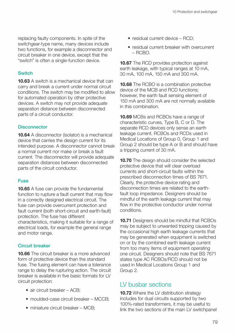
79
10 Protection and switchgear
replacing faulty components. In spite of the switchgear-type name, many devices include two functions, for example a disconnector and circuit breaker in one device, except that the “switch” is often a single-function device.
Switch10.63 A switch is a mechanical device that can carry and break a current under normal circuit conditions. The switch may be modified to allow for automated operation by other protective devices. A switch may not provide adequate separation distance between disconnected parts of a circuit conductor.
Disconnector10.64 A disconnector (isolator) is a mechanical device that carries the design current for its intended purpose. A disconnector cannot break a normal current nor make or break a fault current. The disconnector will provide adequate separation distances between disconnected parts of the circuit conductor.
Fuse10.65 A fuse can provide the fundamental function to rupture a fault current that may flow in a correctly designed electrical circuit. The fuse can provide overcurrent protection and fault current (both short-circuit and earth-fault) protection. The fuse has different characteristics, making it suitable for a range of electrical loads, for example the general range and motor range.
Circuit breaker10.66 The circuit breaker is a more advanced form of protective device than the standard fuse. The fusing element can have a tolerance range to delay the rupturing action. The circuit breaker is available in five basic formats for LV circuit protection:
• air circuit breaker – ACB;
•moulded-case circuit breaker – MCCB;
•miniature circuit breaker – MCB;
• residual current device – RCD;
• residual current breaker with overcurrent – RCBO.
10.67 The RCD provides protection against earth leakage, with typical ranges at 10 mA, 30 mA, 100 mA, 150 mA and 300 mA.
10.68 The RCBO is a combination protective device of the MCB and RCD functions; however, the earth fault sensing element of 150 mA and 300 mA are not normally available in this combination.
10.69 MCBs and RCBOs have a range of characteristic curves, Type B, C or D. The separate RCD devices only sense an earth leakage current. RCBOs and RCDs used in Medical Locations of Group 0, Group 1 and Group 2 should be type A or B and should have a tripping current of 30 mA.
10.70 The design should consider the selected protective device that will clear overload currents and short-circuit faults within the prescribed disconnection times of BS 7671. Clearly, the protective device rating and disconnection times are related to the earth-fault loop impedance. Designers should be mindful of the earth leakage current that may flow in the protective conductor under normal conditions.
10.71 Designers should be mindful that RCBOs may be subject to unwanted tripping caused by the occasional high earth leakage currents that may be generated when equipment is switched on or by the combined earth leakage current from too many items of equipment operating one circuit. Designers should note that BS 7671 states type AC RCBOs/RCD should not be used in Medical Locations Group 1 and Group 2.
LV busbar sections10.72 Where the LV distribution strategy includes for dual circuits supported by two 100%-rated transformers, it may be useful to link the two sections of the main LV switchpanel

80
Health Technical Memorandum 06-01: Electrical services supply and distribution (2017 Edition)
via a “bus coupler-bus-tie” (see Figure 14). However, maintenance access to the bus coupler may require the full isolation of the switchpanel. Although such devices have low maintenance requirements, it may also be useful to consider splitting the LV switchpanel into two sections, linked by a cableway and two four-pole ACBs with Castell key interlocks. An advantage of such an arrangement would allow a fire barrier wall to be installed between the two sections increasing resilience.
Discrimination of protective devices10.73 BS 7671 requires that the characteristics and setting of a protective device for overcurrent should provide any intended discrimination within its operation. A protection study should be carried out by the designer or an independent protection specialist to ensure that all HV and LV protection devices are correctly discriminated to meet the agreed distribution strategy.
Note:
The use of MCBs on some final circuits may cause unwanted tripping (for example, using MCBs (or RCBOs) on lighting circuits, where the non-linear transient current of the inductive control circuit may cause early tripping of the protective device by its magnetic trip.
10.74 RCDs will provide earth fault protection. In order to discriminate between two RCDs as the upstream and downstream protective devices, designers need to use the time-delay setting on the upstream device.
10.75 Designers may wish to consider that full discrimination may not be required on all circuits. Opportunities exist to take advantage of a grading between fuse element curves. Where the discrimination is a little uncertain and the risk of such relative high fault currents are low, the circuit is said to have “limited” discrimination and may be acceptable. The
advantage here would be the reduced size of protective devices, especially with the more upstream devices.
Automatic load management of switchgear (HV, LV)10.76 Design of the electrical infrastructure and distribution strategy should minimise the effect of an electrical fault to the clinical risk areas, but the most resilient system cannot totally eliminate the risk. The fundamental reasons electrical systems have protective devices is to limit the effect of a fault. Effective discrimination and correct selection of protective devices will isolate the smallest appropriate section of the infrastructure. Best-practice distribution strategies may provide an alternative supply route which could be initiated more quickly or safely than replacement of a protective device.
10.77 The distribution system may initiate the standby generator plant until the fault is rectified or isolated. The reconfiguration of an electrical network may be made manually or automatically.
10.78 Where the network is an HV ring circuit (open or closed), the operation of a protective device may result in the standby generators supplying some areas.
10.79 Healthcare premises with significant sections of clinical risk grade C areas and above (see Chapter 4) may benefit from quick reconfigurations of the electrical distribution following a fault on the network. Therefore the use of a supervisory control and data acquisition (SCADA) computer system to automatically control the switchgear status and reconfigure the network(s) would be useful. Resilience will be improved by providing N+1 controller configuration. SCADA systems are modular in design and may be added to retrospectively. The SCADA system can be applied to any part of the HV and/or LV networks including all power sources.
10.80 SCADA systems should be hard-wired with monitored circuits wherever they are used.

81
11 Tertiary power supplies
11 Tertiary power supplies
11.1 Tertiary power supplies should not be considered as a long-term energy source in the same way that primary supplies or secondary supplies are used. Tertiary power supplies are generally used as a backup supply for a given period of time (autonomy) or to start SPSs. The batteries considered are those used for a UPS, battery inverter units and batteries used to start standby generator engines.
11.2 Batteries used in control systems such as motor drives or electric vehicles have been excluded from this Health Technical Memorandum. The foregoing exclusions are justified, as their respective systems do not form part of the fixed wiring systems of healthcare premises.
11.3 The tertiary power supplies considered are:
•batteries for UPS systems, inverter units and generators;
•HV/LV tripping/closing batteries;
•UPS systems;
• inverter units for central battery units and theatre operating lights.
Batteries for UPS systems, inverter units and generators
Batteries for UPS systems
Battery type
11.4 There are a number of battery-cell types in use today for UPS applications. The most
appropriate are the valve-regulated lead-acid (VRLA) battery types, which are more commonly known as sealed lead-acid cells. The VRLA battery is a near-zero-gassing battery cell, and hence presents a lower environmental hazard to the UPS or surrounding area. With no toxic gases emitted from the battery, there are no special venting requirements for the battery unit. The VRLA battery is almost universally used for modern UPS systems due to its low maintenance and reduced requirements for vented gas extraction.
11.5 While ten-year VRLA batteries have higher initial investment costs than standard five-year-life batteries, they offer significant long-term benefits in terms of security of function and reduced long-term costs. VRLA batteries should comply with BS EN 60896 Parts 21 and 22 and incorporate threaded-insert connection posts and flame-retardant case materials.
Battery life and environment
11.6 Battery life is a function not only of load cycling, but of charging methods and the environment. VRLA batteries will function for a short time period over a wide range of temperatures typically from –15°C to +50°C. However, for normal continuous use their ambient operating temperature should be ≈20°C, otherwise their life expectancy will be reduced considerably, typically to 50% at 30°C and to 25% at 40°C. With continued operation at high temperatures, these batteries can also become a fire hazard as the casing can split causing acid to spill, which in turn may result

82
Health Technical Memorandum 06-01: Electrical services supply and distribution (2017 Edition)
in uncontrolled battery DC earth faults. It is therefore very important that the battery location has a suitable environment with adequate ventilation/cooling to maximise battery life. Note that in practical terms, even with the recommended regular maintenance, VRLA batteries are normally changed at 80% of their designed life. Battery life should be in accordance with the range given in Table 3 of Chapter 9.
11.7 Correct charging of batteries is very important; therefore any charger should meet appropriate standards and conform with the battery manufacturer’s requirements.
11.8 Consideration should be given to monitoring the temperature (remote alarm) of the environment in locations containing batteries so rapid action can be taken in the event of a problem.
Battery arrangements
11.9 Designers should consider the opportunities for maintenance of the UPS battery assembly. Batteries can be arranged as single or split banks. The use of split battery banks allows the UPS to remain online (at reduced battery autonomy) while half of the battery system is being serviced.
Battery autonomy
11.10 Single-conversion UPS units are generally used for small personal computers, IT network hub and switch cabinets or computerised processors dedicated to medical/laboratory equipment. Battery autonomy is typically in minutes up to, say, 15 min, depending on the particular application. Single-conversion UPS units are most commonly used to safely shut down systems following an outage of the PES or, depending on the particular need, between the period of mains failure and SPS standby generators becoming available.
11.11 Double-conversion UPS units are most commonly used for tertiary power supplies to dedicated final-circuit outlets, used for example
in clinical risk grade A or B areas (see Chapter 4). The most common application of a double-conversion UPS is to provide tertiary power for Medical IT systems. The UPS batteries maintain an electrical supply following an outage of the PES and prior to the SPS standby generators becoming available. When used as a tertiary power supply to clinical areas requiring a changeover period less than or equal to 0.5 s, typically in Medical Location Group 2, a battery autonomy of 3 h is required. This may be reduced to 1 h if an SPS is available within 15 s. Where the UPS battery provides tertiary power to other applications in operating theatres, the battery autonomy should provide operating theatre staff enough time to facilitate “patient closure” for all theatre cases. Consideration should be given to providing a warning when on battery power so that, for example, new procedures are not started.
11.12 Designers should consult with stakeholders and clinical staff who form part of the Electrical Safety Group to determine the most appropriate battery autonomy in line with the required standards and procedures being performed.
Batteries for inverter units
Battery arrangements
11.13 Three main types of battery arrangement can be found in healthcare premises:
•Batteries within self-contained items such as emergency escape lighting and signage, which are generally in small packs with cells connected in series or parallel series groups. Their physical size allows these battery packs to be replaced in a single step, taking only minutes and affecting only a single unit. This is also a typical arrangement for small single-conversion UPS units.
• The second most common arrangement found is those within self-contained cabinets, often used for central battery units (theatre and emergency lighting),

83
11 Tertiary power supplies
dual-conversion UPS units for Medical IT systems and for inverters used to support general or medical data processing systems.
• The third type of arrangement is where the batteries are contained in racks in plantrooms or other dedicated spaces. These are also for theatre lighting (central battery units) but may also be for large UPS systems intended to maintain a whole interventional X-ray system.
11.14 Battery-cell or battery-string monitoring and alarm facilities should be considered where appropriate.
11.15 Designers should consider the provisions of battery replacement during operation to minimise disruption. For example, the use of split battery banks allows the inverter units to remain online (at reduced battery autonomy) while half of the battery system is being serviced.
Battery autonomy
11.16 Battery inverter units used for self-contained emergency escape lighting and signage have a battery autonomy of 3 h as required by BS EN 1838 and BS 5266. Central battery units for emergency escape lighting should also have a battery autonomy of 3 h.
11.17 Battery inverter units for theatre operating lamps should, in accordance with BS 7671, have a minimum battery autonomy of 3 h.
11.18 Battery autonomy for fire alarm and detection systems, or other alarm systems, should meet the requirements of BS 5839-1. Currently this requires sufficient autonomy to drive the systems (in quiescent mode) for 24 h, followed by a 30-minute period where all sounders, indicators and communications are operated with the normal sound pressure level outputs. For a healthcare facility that may be closed over a weekend and bank-holiday period, an autonomy of 100 h may be more appropriate. This requirement is independent of any SPS that may be available.
Generator batteries
Battery autonomy
11.19 Generator batteries are normally specified for x ampere-hours (Ah), where the battery capacity x should be able to provide sufficient power when discharged by 25% to attempt three successive starts each of ten-second duration with a three-second interval, while the ambient temperature is 0°C. Generator battery systems should be capable of turning the generator engine continuously for 60 s at an ambient temperature of 0°C.
11.20 Usually two battery-charging systems are supplied with a generator set:
• the constant charger is a charger for operation while the set is stationary, usually in the control panel; and
• a belt-driven charge alternator maintains the battery when the set is running.
11.21 For both charging systems the battery should be charged at the correct float voltage. For engine starting, the battery should be adequately sized for the breakaway (initial starting) voltage to be acceptable to the engine manufacturer.
Batteries and chargers for HV/LV switchgear protection and control11.22 Battery tripping and charger units can be used for HV and/or LV circuit-breaker tripping and closing supplies of switchgear.
11.23 The battery and charging arrangement should be suitable for the protection and control system it is supplying, and selected and sized in conjunction with the switchgear manufacturer to cover all switching and protection operations. The design of the battery tripping and charger units should incorporate a system for testing the batteries for charge available as well as terminal voltage and battery condition.
11.24 The tripping/closing batteries should be fully rated and include an overload capacity to
84
Health Technical Memorandum 06-01: Electrical services supply and distribution (2017 Edition)
support the full burden of the complete load with battery autonomy for 8 h. Due to the critical nature of the protection system, the tripping/closing DC system consideration should be given to the provision of dual-rectifier–dual-battery systems. As a minimum, the designer should consider dual rectifiers. The alarm outputs from the rectifier should be relayed to the BMS.
Uninterruptible power supplies11.25 This section deals with UPS arrangements for the emergency protection of final outlets, circuits and equipment. The configurations are presented generally in order of resilience from low to high. The selection of a particular configuration will be dependent on the specific factors of each individual design. The selected configuration should be based on a risk analysis to determine the appropriate level of resilience.
Standards11.26 UPS systems should be to, but not be limited to, the following design and manufacturing standards:
•BS EN 62040-1;
•BS EN 60146-1-1;
•BS EN 61439-6;
• the Energy Networks Association’s G5/4-1.
Rating11.27 UPS system ratings range from 250 VA up to several hundred kVA; the small units may be single-phase units used to support a single circuit, and the larger UPS systems may be single- or three-phase units for supporting a complete department.
11.28 Central UPS systems may be considered where the need covers several small distributed areas. Designers should be aware that providing central UPS systems may increase the risk of single points of failure affecting a larger area (and potentially more departments). Risks to consider include the routing, location and segregation of
UPS distribution cabling and switchboard configuration designed to avoid a single fire or fault affecting the whole system. These should all be carefully considered in consultation with appropriate stakeholders from the Electrical Safety Group, weighing the potential cost benefit against higher risk.
11.29 Where centralised UPS systems are considered, a diesel rotary UPS (DRUPS) may provide an economic solution. The location of DRUPSs should be based on the same environmental criteria used for the standby generators and/or CHP plant.
11.30 Other types of rotary UPS, which use the stored energy of a flywheel under full torque connected to a motor, may also be used. The autonomy of these UPS devices is essentially time-based and largely independent from the actual load. These so-called silent rotary UPS currently have high kVA ratings and are more suited to a centralised system.
UPS environment11.31 Designers should consider the local space and location of the UPS in terms of floor loading, access for maintenance, the heat generated, and room conditions such as dust and proximity to wet services (especially when located above), which may affect equipment life, reliability and resilience. Depending on the UPS type, single- or double-conversion, a UPS will radiate about 3% to 8% of its input power, which will need to be vented. Ideally, the ventilation should be natural. The environmental conditions should control the room space to the limits recommended by the manufacturer.
UPS description and configurations11.32 The UPS module should comprise five principal components:
a. rectifier module (converts alternating voltage to DC voltage) to a DC bus;
b. inverter module (converts DC voltage to alternating voltage);
c. battery (provides uninterruptible power to a DC bus);

85
11 Tertiary power supplies
d. static bypass switch;
e. maintenance bypass switch (to enable maintenance of principal components).
11.33 The rectifier output should maintain the battery in a fully-charged condition.
11.34 The inverter should reconvert the rectifier output (or battery output) to a synthetic sinusoidal waveform output (either single- or three-phase according to the input).
11.35 The static bypass will electronically divert the normal UPS load output from the rectifier inverter line through the static switch whenever a fault in the UPS conversion occurs and/or should a fault occur in the load side of the UPS. The static bypass operates at such a high speed that it is considered as a no-break supply switch.
11.36 Single-conversion UPS units are configured so that the supply is normally via the static switch and, on loss of supply or when the supply quality falls, the static switch connects the battery output to the load. The battery is held fully charged by a trickle charger supplied from the normal supply. The battery autonomy of single-conversion UPS working offline is typically up to 15 min.
11.37 Double-conversion UPS units are configured so that the supply is normally via the rectifier and inverter line and, on loss of supply (or poor supply quality), the battery output supplies the load via the inverter. The static switch will also bypass the rectifier inverter if the UPS circuit develops a fault. The battery is held fully charged by a trickle charger supplied from the normal supply.
11.38 The rectifier and bypass may have a common supply connection. The ideal connection should provide separate connections for the rectifier and bypass line. Where, for resilience purposes, UPS units are fed from different PES transformers, the UPS may experience neutral referencing problems. This should be discussed with the manufacturer at the time of design and appropriate measures introduced.
UPS load considerations11.39 Diagnostic systems vary in functionality and operation. The majority of diagnostic systems when in operation draw large and varying transient currents.
11.40 These transient currents vary in both magnitude and time duration. As UPS systems are generally rated to provide full rated output with a limited overload capability but in magnitude and time duration, any transient current in excess of the specified threshold, may trigger the UPS to switch to its static bypass to protect itself.
11.41 If this occurs, then the main function of the UPS is compromised and uninterruptible power supply will not be assured should a power failure occur during the transient event.
11.42 The designer should consult with the medical diagnostic manufacturers/suppliers to establish the full operating characteristics of the proposed equipment.
UPS fault condition design11.43 UPS protective devices should be capable of clearing downstream circuit faults in similar fashion to other distribution boards. UPS output-circuit protective devices should discriminate from upstream devices. Designers should consider the effect of overload and short-circuit fault conditions. Short circuits in the UPS load are isolated either by a downstream protective device or by the insulated-gate bipolar transistor (IGBT) control circuit of the inverter. UPS units may tolerate overloads of 125% for 10 min, 150% for 1 min, or 200% for 100 ms (depending on the manufacturer’s selected internal protective device). The actual overload characteristics vary from manufacturer to manufacturer. Designers should verify the coordination of fault conditions when selecting the UPS type.
11.44 Designers need to consider carefully the protection systems used by the UPS. The UPS final-circuit protective devices should provide adequate discrimination with the inverter/static switch protection. If the inverter/static switch

86
Health Technical Memorandum 06-01: Electrical services supply and distribution (2017 Edition)
protection operates before the final-circuit protection, the UPS may shut down. Clearly, this would then isolate all the final circuits and not just the faulty circuit.
11.45 With three-phase UPS units, designers may wish to consider the use of a zigzag transformer on the UPS bypass lines. Such transformers provide a local earth point, may help to ensure that an adequate fault current is developed, and assist in harmonic control. The actual earth-loop impedance at the load end will vary significantly depending on how far the UPS system is from the source transformer neutral-earth connection. As a result, higher than accepted earth-loop impedances can be recorded and the test results may not satisfy the requirements of BS 7671 disconnection times. To maintain the integrity of the neutral-earth reference, UPS manufacturers will request three-pole protective devices in the supply lines supplying the UPS systems. In accordance with BS 7671 where a UPS is used as an electrical source for life-safety systems, it should be able to operate distribution circuit protective devices.
11.46 Where the UPS is supported by the SPS, a transformer with a double-wound secondary may assist with the limiting of the initial acceptance load as the harmonic currents have been reduced.
11.47 Where the changeover arrangement utilises four-pole devices from primary source to the secondary source, the neutral-earth reference will be lost for the period that actual changeover takes place. The risk of an unstable output will depend on the load distribution of the UPS. The more unbalanced, the higher the risk. The optimum solution is to provide a dedicated zero-phase shift transformer on the UPS system.
11.48 The isolation transformer can be located in a number of points on the UPS system which can be as follows:
a. input supply to the UPS module (complete module);
b. input supply to static and maintenance bypass;
c. output of the UPS system.
Item (c) is the optimum option although it comes with added costs and may impose on available space. Therefore all options should be discussed with the equipment supplier at design stage.
11.49 UPS systems should be designed to provide multiple alarm outputs to enable remote monitoring and status indication.
UPS power quality11.50 A UPS is a significant source of non-linear current and may have a significant effect on the electrical supply system it is connected to. The rectification stage provides a pulsed ripple DC circuit, and the inversion stage provides a synthetic sinusoidal AC circuit. Thought should be given to UPS units which use IGBTs and to the duration and value of any inrush currents.
11.51 The output of the rectifier will be a ripple DC voltage. The ripple effect is normally smoothed by the use of IGBT devices. However, the IGBT circuitry will reflect a harmonic current into the supply line. The level of harmonic currents should be controlled such that the net harmonic current reflected to the PES is in accordance with the Energy Networks Association’s Engineering Recommendations G.5/4-1. See also paragraphs 6.11–6.19.
UPS resilience11.52 UPS units can be grouped as multiple units connected to provide N+1 resilience as described in paragraphs 7.10– 7.41. With redundant UPS arrangements, each UPS should be able to fully support the full load.
11.53 There are several configurations for UPS systems, all of which depend on the application – for example, Group 2 Medical Locations, diagnostics and information processing systems. The UPS configurations shown in Figures 21–25 are provided for guidance only and the designer should demonstrate that any solution provided is the optimum solution to maintain both patient safety and their associated systems where loss of power will have an effect on normal operation of the healthcare facility.

87
11 Tertiary power supplies
11.54 Figure 21 shows a typical basic configuration of a UPS system and demonstrates the extent of isolation for a simple single-phase unit. The isolation transformer is indicative for design consideration only. In a new building, the electrical infrastructure for Group 2 Medical Locations, or where support systems are considered high risk, the electrical supply should be designed around a dual distribution system and the UPS should follow the same principle, that is a dual system
11.55 For resilience, Figure 22 demonstrates a configuration that will support a dual UPS system where each UPS is rated for 50% of the load required through two Medical IT systems. For greater resilience, each UPS may be rated at 100% load with interleaved autochangeover provided to support the full load to all the Medical IT requirements (see Figure 23).
Staff base
Figure 21 Basic UPS system showing bypass panel: single module (typical)

88
Health Technical Memorandum 06-01: Electrical services supply and distribution (2017 Edition)
Mains Bypass Breaker c/w Interlock to
UPS Static Bypass
UPS Supported Load
Mains Bypass Breaker c/w Interlock to
UPS Static Bypass
UPS Supported Load
Breaker Isolator BreakerIsolator
A BMedical IT socketnumber as specified
50%+50%
Isolator
Isolator Isolator
Isolator
K Inter-locking KeyDrive UPS to bypass
K Receptor
KInter-locking KeyDrive UPS to bypass
KReceptor
R I RI
Dual String Battery with protective device if separate from UPS
Alternative Location forZero Phase Shift TransformerSeek Manufacturers Advice
Group 2Medical Location
Zero-phase shift transformer to be considered at design stage if loss of neutral-earth reference during upstream mains generator changeover considered a risk to downstream devices and/or equipment. Manufacturers should be consulted.
UPS mains supply UPS mains supply
Medical ITA
Medical ITB
UPS input – output panel A UPS input – output panel B
Figure 22 Basic UPS system: single module

89
11 Tertiary power supplies
Figure 23 UPS system N+1
Mains bypass Breaker c/w Interlock to UPS Static Bypass
UPS Supported Load
Mains Bypass Breaker c/w
Interlock to UPS Static Bypass
UPS Supported Load
Breaker Isolator BreakerIsolator
A BsocketsNumber as specified
100%UPS+Medical IT
Isolator
Isolator
Isolator Isolator
Isolator
K Inter-locking KeyDrive UPS to bypass
K Receptor
KInter-locking KeyDrive UPS to bypass
--
R I RI
Dual String Battery with protective device if separate from UPS
Dual String Battery with protective device if separate from UPS
Alternative Location forZero Phase Shift TransformerSeek Manufacturers Advice
Alternative Location forZero Phase Shift TransformerSeek Manufacturers Advice
Medical IT
Medical ITGroup 2
Medical Location
UPS mains supply UPS mains supply
UPS input – output panel A UPS input – output panel B
Auto no-break switch
AMedical IT
B
Zero-phase shift transformer to be considered at design stage if loss of neutral-earth reference during upstream mains generator changeover considered a risk to downstream devices and/or equipment. Manufacturers should be consulted.

90
Health Technical Memorandum 06-01: Electrical services supply and distribution (2017 Edition)
11.56 The configuration in Figure 24 (N+N) for both UPS and Medical IT systems should be considered for Medical Locations of Group 2. Other configurations may suit other individual areas such as information processing centre (IPC) systems where parallel synchronous systems may be more appropriate.
11.57 The configuration in Figure 25 can suit the application for IPC/information technology where the N+1 solution offers increased resilience/redundancy. Designers should consult with the IPC/information technology stakeholder through the Electrical Safety Group as to the level of UPS support they require.
11.58 In existing buildings where UPS systems are mostly retrofit, a desktop design – while appearing the optimum solution – may not work due to space limitations, lack of alternative supplies, weight limits on structural floors, etc. A bespoke design solution will need to be considered. Therefore, in all cases the designer should demonstrate that the optimum solution has been provided. The configuration in Figure 25 giving (N+1) can be a solution where space is at a premium and/or where growth is possible. Modular systems are available with options to expand when required depending on the load needed.
Mains Bypass Breaker c/w
Interlock to UPS Static Bypass
Dual String Battery With Protective device if separate from UPS
UPS Input – Output Panel
UPS “Mains” Supply-Source
UPS Supported Load
Breaker Isolator
Load 1(A)
Isolator
Isolator
UPS Supported Load
Isolator
Load 1 (B)
KInter-locking KeyDrive UPS to bypass
K
IR
R I
Dual String Battery with protective device if separate from UPS
Alternative Location forZero Phase Shift TransformerSeek Manufacturers’ advice
Zero-phase shift transformer to be considered at design stage if loss of neutral-earth reference during upstream mains generator changeover considered a risk to downstream devices and/or equipment. Manufacturers should be consulted.
Figure 24 Dual UPS N+N

91
11 Tertiary power supplies
11.59 In all configurations, additional operational status may be provided by an autochangeover resilient supply to the SPS and/or manual changeover to an alternative supply in the event of distribution failure.
11.60 Bypassing and isolating a UPS system under emergency conditions is an important requirement. This may be the last option that the Authorised Person has in restoring power supplies to critical areas in an emergency.
11.61 Facilities should be provided to enable the Authorised Person to quickly and safely
bypass the UPS system in the event of catastrophic failure.
11.62 Where appropriate, the UPS should have the facility to be completely withdrawn from service and replaced with no impact on normal service during the change.
Inverter units
Central battery units11.63 The wiring used in central battery units should be of an enhanced grade as defined by BS 5839-1.
Mains Bypass Breaker c/w
Interlock to UPS Static Bypass
–
UPS “Mains” Supply-Source
UPS Supported Load
Breaker Isolator
Load 1(A)
Isolator
Isolator
Dual String Battery with protective device if separate from UPS (Note1)
UPS Supported Load
Isolator
Load 1 (B)
K
Removal ofInter-locking KeyDrive UPS to bypass
K
R I
S/Switch
IR
R I
Zero-phase shift transformer to be considered at design stage if loss of neutral-earth reference during upstream mains generator changeover considered a risk to downstream devices and/or equipment. Manufacturers should be consulted. Note: transformers can be located at different points of the UPS.
Figure 25 Dual UPS: parallel synchronous mode

92
Health Technical Memorandum 06-01: Electrical services supply and distribution (2017 Edition)
11.64 Central battery inverter units should be directly connected to the SPS and be so arranged that the output can energise all connected emergency escape lighting and signage within 5 s as required by BS 5266.
11.65 Central battery inverter units should be constructed with maintenance bypass switches. The switch should isolate the battery-charging unit and the batteries from the output, but maintain a normal supply to the output.
Note:
If there were to be an outage of the primary supply during the maintenance of a central battery inverter unit, there would be no output supply until the SPS were available. This period of approximately 15 s is beyond the 5 s requirement of BS 5266. See paragraph 11.16 for details of the battery capacity relating to central battery inverter units. See also Chapter 17.
Theatre operating lamps11.66 Each separate operating theatre should have its own inverter battery unit, external to the theatre, exclusively for the operating lamp(s).
11.67 See paragraph 11.17 for details of the battery capacity relating to inverter units for theatre operating lamps.

12 Electromagnetic compatibility
93
12 Electromagnetic compatibility
Introduction12.1 Electrical installations must be compliant with the requirements of the Electromagnetic Compatibility (EMC) Regulations. The regulations describe the electrical installation requiring suitable design, erection and maintenance to be in place to ensure electromagnetic compatibility, and BS 7671 contains requirements for electromagnetic compatibility that should be considered. Procurement contracts for electrical equipment associated with the distribution of the electrical installation should stipulate that the equipment must be compliant with the EMC Regulations and all relevant legislation.
12.2 From the point of view of the legislation, it is not sufficient to integrate CE-marked equipment and claim that the large “system” complies simply because compliant equipment has been used. Compliance of the large “system” should be demonstrated either by testing and/or by presentation of a rationale as to why the system complies. EMC surveys and compliance testing may involve pre-design, commissioning and post-handover EMC measurements, and such activities in areas such as plantrooms and switchrooms will require a limitation-of-access safety document as per Health Technical Memorandum 06-02.
12.3 Other legislation contains EMC requirements, including the Medical Devices Regulations and the Radio Equipment and Telecommunications Terminal Equipment Regulations, and may take precedence over the EMC Regulations. These may impose additional or alternative requirements for a particular
product dependent on its use. Critically for the healthcare environment, it is important to ensure that any equipment that can be classified as ME equipment complies with the relevant standards and regulations, which are often more stringent than contemporary product standards for equipment in other environments.
Note:
The new Medical Devices Regulations are expected to come into force in May 2017. There may be a transition period for product standards identified in the legislation.
Roles and responsibilities12.4 The EMC Regulations describe who is responsible for meeting compliance.
12.5 It will not always be possible to design-in equipment that is CE-marked to show compliance with the Regulations. An installation may comprise CE-marked and non-CE-marked equipment. Supply of non-CE-marked equipment is acceptable providing the installer who is integrating them into the system can be sure that they will not cause undue interference to the installation or be overly sensitive to the electromagnetic environment where the equipment will be used.
12.6 The designer should obtain a technical file from the installer demonstrating that good engineering practice has been applied, and should show details of any concessions granted to items that are not compliant with the

94
Health Technical Memorandum 06-01: Electrical services supply and distribution (2017 Edition)
installation specification, but which may be used without detrimental effects.
12.7 ME equipment supplied for operation in clinical areas should have sufficient immunity to operate successfully in that environment, and it should not emit excessive radiation.
Standards for equipment12.8 The EMC Regulations require that those who supply relevant equipment show that:
• it conforms to the protection requirements;
• it meets the conformity assessment requirements;
• the CE-marking is properly applied;
• it has a declaration of conformity certificate (DOC) conforming to BS EN ISO/IEC 17050-1.
12.9 Data should also be provided for the end-user to ensure that these requirements are satisfied throughout the operational life of the equipment.
Procurement requirements for equipment and installations12.10 Problems from electromagnetic interference (EMI) will be minimised by procuring equipment that:
• complies with relevant standards;
• is supplied with a relevant EMC DOC; and
• is installed and maintained using good EMC practices.
12.11 It is essential that those designing and specifying equipment and installations for use in the healthcare environment give their relevant purchase departments an EMC specification that is sufficiently detailed for suppliers to be aware of their contractual obligations with respect to EMC.
12.12 Procurers, system integrators and designers should be knowledgeable about the EMC performance levels that equipment is expected to meet when correctly installed and operated. To be able to distinguish between the requirements and declarations of compliance statements for the various pieces of legislation, a procurement document should be written that covers such legislation.
12.13 EMC requirements should consider appropriate standards. The relevant websites should be consulted for harmonised standards, reference to which has been published in the Official Journal of the European Union (OJEU).
Electromagnetic environment12.14 The environment within a building is made up of sources that are located within the building (that is, equipment that is the source of electromagnetic radiation, for example transformers, MRI suites) and sources that are generated externally to the building. The external sources will usually be intentional transmitters, together with strong radiating unintentional transmitters such as any railway infrastructure adjacent to the premises (see Table 5).
12.15 BS EN 60601-1-2 has radiated immunity test requirements up to the 5800 MHz band; however, that does not mean that assessment of the impact of these on ME equipment can be ignored, as the product tests only demonstrate immunity to limited disturbance levels, and may omit certain bands as technology advances.
12.16 Emergency services’ mobile units (PMR and TETRA) operate at much higher transmission levels than GSM mobiles and can be expected to be present in the non-specialist areas of healthcare premises, that is, clinical risk grades C–E inclusive (see Chapter 4). Building and system control panels located in corridors will be subject to these higher levels.
12.17 In hospitals particularly, cable lengths in excess of 30 m, running either horizontally or vertically, will be encountered. These lengths

12 Electromagnetic compatibility
95
are ideal for picking up and conducting frequencies up to around 400 MHz. System designers should always consider the use of screened cables, metal trunking and cable ladders to minimise interference into plant or building systems equipment.
Designing systems for EMC control12.18 EMI does not stop at interfaces, either conducted on cables or radiated. The positioning of mechanical and electrical (M&E) systems within the building has the potential to affect the performance of other installed systems.
12.19 The electromagnetic environment should be divided into zones where equipment will be compatible for both emissions and immunity. At boundaries, a risk assessment will be required to determine whether mitigation measures need to be implemented to reduce the potential cross-boundary interference or whether a product is suitable for use in a particular electromagnetic environment.
12.20 Cabling, containment, screening, separation and earthing, and installation practices should follow, as a minimum, BS IEC 61000-5-2, BS 7671, BS EN 50310 and the BS EN 50174 series.
EMC control for power systems12.21 It is important that the electrical installation meets the expected EMC standard for the ME equipment that is to be connected, for example, total harmonic distortion below 5%.
12.22 UPS systems and battery rectifiers are a source of mains-injected harmonic interference. For this reason, they should be located in zones away from equipment which may be affected by their emissions, for example IT systems.
12.23 Power transformers are a concentrated source of low-frequency magnetic interference. For each type, their location and cubicle screening should be considered in relation to sensitive equipment (that is, those likely to be affected by radiated magnetic fields). This particularly applies to theatres where cathode ray tube systems are used, as on-screen distortion effects will occur. The influence of the transformer and the route of unscreened or single-core main LV cables should not be ignored. There may be magnetic coupling with
Frequency (MHz) Description
70–85 Fire and rescue radio
122.15 Air band communications
153.675 Pagers
170.65 PMR mobiles
197.325 PMR mobiles
380–430 TETRA 400
430-470 PMR, GMRS 460, FRS 460
461.65 PMR mobiles
450 Police radio
486–606 TV broadcasting band
704-787 Future mobile data network allocation (LTE Bands 13, 17)
800-960 2G, 3G and 4G mobiles. GSM 800/900, TETRA 800, iDEN 820, CDMA 850, LTE Band 5
1700-1990 2G, 3G and 4G mobiles and cordless phones. GSM 1800; CDMA 1900; GSM 1900; DECT; LTE Band 1, 3,
4, 25; UMTS
2400-2570 Wi-Fi wireless networking, public access points, Bluetooth, radio frequency identification systems, 4G mobiles. Bluetooth, WLAN, 802.11 b/g/n, RFID 2450, LTE Band 7
2500-2690 UK 3G UMTS and 4G LTE Data Networks
3480-3690 4G LTE Data Networks
3650-3700 Wireless data transmission networks.
4915-5825 Wi-Fi wireless networking, public access points. WLAN
802.11 a/n
Table 5 Electromagnetic sources

96
Health Technical Memorandum 06-01: Electrical services supply and distribution (2017 Edition)
the steel and reinforcement bars of the building structure, thus inducing a network of currents flowing in the steel to earth with associated localised secondary magnetic fields.
EMC control for cables and cable-containment systems12.24 Single-phase power cables, including power feeds and lighting circuits, carrying up to 250 V should not be grouped with sensitive cables (that is, data cables).
12.25 No data, telecommunications or any other sensitive cabling should be placed near three-phase cables, as these are normally used for heavy electrical inductive loads (for example, air-conditioning, welding equipment and motors).
12.26 All cabling should avoid any close proximity to radio or television transmitters, beacons and overhead transmission lines.
12.27 Cables carrying high-level impulse energy produce a large frequency distribution of disturbances due to their fast rise times. Special precautions need to be taken with these types of cabling: efficient screening, earthing at both ends, and an increase in the separation with adjacent cables would need to be implemented.
12.28 The characteristic impedance of cables should be selected to match closely the impedance of the terminating equipment. This reduces the amplitude of standing waves created by reflections due to mismatches in impedance transition.
12.29 All power-cable screens or armour should be bonded at both ends of the run to an earth plate using 360-degree peripheral glands.
EMC control for general systems12.30 Personal transmitters/receivers, main transmitters and local radar devices should be evaluated to ensure that they do not cause random operations or failure of electronically controlled equipment. Personal transmitter/receivers are particularly likely to cause this problem.
Intentional apertures
12.31 Apertures are always required in rooms to allow services to enter and leave. Rooms that are required to have a screen to prevent EMI in the healthcare environment can use similar techniques for screening apertures to allow services to enter.
Cable segregation and separation12.32 To reduce the possibility of power-cable to signal-cable coupling and the associated EMC risks, the best approach is to use separation between power and sensitive service cables. Fire-alarm cables should be run in a separate conduit from other service types. Signal and telecommunications cables should not be run in the same tray as power cables.
12.33 Minimum separation between power and signal cables, under various conditions, are specified in BS 7671, BS EN 50174-2 and BS EN 50174-3. These are minimum separation distances for certain specified conditions, and a particular application may require a greater separation. These standards include specific criteria and circumstances where zero separation may be acceptable. Where zero separation is to be adopted, the designer should be satisfied that the conditions for zero separation will continue to be maintained during the service life of the installation. Where power and signal cables are required to cross, the angle of their crossing should be maintained at 90 degrees on either side of the crossing for a distance no less than the applicable minimum separation requirement.
Note:
Cable screening should be bonded to an earth return at both ends of the cable; this is supplemented by a common bonding network, as described in BS EN 50310, adequately specified and implemented to ensure that earth-loop effects are eliminated.

12 Electromagnetic compatibility
97
12.34 For signal cabling between buildings, BS EN 50174-3 should be followed. Signal cables installed outside or beneath buildings should also be physically separated from earth electrodes of power systems in accordance with BS EN 50174-3. Where signal cables pass between buildings, the safety requirements in BS 7671 should be met for conductors connecting the earthing systems of installations with separate earthing arrangements.
Cable screening, trunking and trays12.35 Various types of cable tray or conduit may be used and run in parallel over an appreciable distance. The crosstalk between the cables they contain may be important.
Crosstalk characteristics12.36 Cables with a low crosstalk may require shielding against the (magnetic) fields causing the crosstalk currents.
12.37 Using trays or racks of sufficient wall thickness to separate cables can provide both a parallel earth path and a reduction in crosstalk. They can often be laid next to each other.
12.38 Solid trays or slotted trays with slots parallel to the tray are preferred. Caged trays constructed with large gaps in the screen should certainly not be used where electromagnetic screening is an issue, as they offer no screening benefits.
Trunking and tray interconnection and termination12.39 When a metallic cable tray or trunking system is implemented, inevitably sections will need to be interconnected for extended runs. Particular care will be necessary in order to maintain electrical continuity between the various sections.
Using conductive structural supports as runs for cables12.40 Metallic structural support elements in buildings can also serve EMC objectives where room for cable trays or trunking is limited. Steel beams of L-, H-, U- or T-section can form a continuous earthed structure that offers relatively large cross-sections and therefore low impedance and large surfaces with many potential intermediate connections to earth. Cables can be laid against such beams as shown in Figure 26.
Systems and cabling impacted by metallic containment, supports and services12.41 Certain systems by their very nature may have their performance severely impaired or completely curtailed by metallic containment, cable/containment supports, structural elements and services.
12.42 The location of cables for audio-frequency induction loops and leaky-feeder-type transmissions should be carefully considered in
Recommended Acceptable Not recommended
Figure 26 Location of cables inside metallic structural supports

98
Health Technical Memorandum 06-01: Electrical services supply and distribution (2017 Edition)
light of the performance requirements of the system. Audio-frequency induction loops should be assessed in accordance with BS 7594 and BS EN 60118-4.
12.43 Signals to and from systems that rely on radio transmission (for example, wireless data networking and internet access points (Wi-Fi)) are impaired or sometimes blocked by absorption in nearby metalwork of any kind. The location of metallic containment and services should consider the impact on radio and wireless signals for such systems.
Identification of critical systems12.44 M&E equipment is designed to comply with either generic industrial standards or product-specific standards. Such equipment will be generally immune when located in its intended environment. Designers should identify environments where levels higher than those specified in standards will be encountered and apply mitigating measures (for example, prevention of the use of mobile phones close to control systems while screening enclosure doors are open). Many M&E systems not normally considered critical are critical when their malfunction causes reduced operational efficiency (for example, heating and ventilation systems and fire-alarm systems).
Earthing and bonding12.45 Earthing is the connection of the exposed conductive parts of an installation to the main earthing terminal of that installation. Bonding is an electrical connection maintaining various exposed conductive parts and extraneous conductive parts at substantially the same potential. Earthing arrangements are described in detail in Chapter 13. Good EMC practice for earthing and bonding of installations should follow BS IEC 61000-5-2, BS 7671 and BS EN 50310.
12.46 Earthing is also used to contribute to the mitigation of disturbances for installations with sensitive and interconnected electronic and
electrical systems. The following EMC implementation rules should be used.
12.47 Wherever possible, the TN system should be used. Exceptions exist with IT-configured systems or where a high continuity of supply is required.
12.48 Non-linear loads (fluorescent lamps, switched-mode power supplies, etc.) on distribution networks can generate harmonic currents which may overload the neutral conductor. Correction methods for such systems are provided in Chapter 6. The controlled earth return current of a TN system is shown in Figure 27.
12.49 Good earthing practice utilises dedicated earth conductors, which are fed back to the main earth terminal (MET), in addition to, and reinforcing, protective earthing conductors selected on the grounds of safety. This helps to minimise potential differences between parts of an installation, which affects interconnections between locations, particularly telecommunications and control cabling. Protective conductors of cables formed purely from ferrous metal (for example, steel wire armour) may exhibit high inductive impedances and should be reinforced with lower impedance cabling to make an effective common bonding network to manage higher frequencies.
12.50 Maintaining an equipotential between all the cabinets in an equipment room, data centre or similar location where high concentrations of electronic equipment can be found is important for EMC control. The likelihood that this can be achieved is increased by a localised connection to the mesh bonding network or grid of the room.

12 Electromagnetic compatibility
99
PE
NL
TN earthing network
Controlled flow ofreturn currents
Cabinet frameground
Main distribution boardearth bar
Main buildingearth mat
Common bonding network including trays, pipes and ducts.Connection via PE
Figure 27 Controlled returned current flow in a TN installation

100
Health Technical Memorandum 06-01: Electrical services supply and distribution (2017 Edition)
13 Earthing
13.1 The earthing arrangements and protective conductors for the electrical system should comply with the requirements of BS 7671, BS 7430 and BS EN 50522.
HV earthing (see BS EN 50522)13.2 Where the PES is rated at high voltage (up to 11 kV) and the termination point is at low voltage (0.4 kV), the responsibility of the HV earthing will lie with the DNO. Where the healthcare organisation meters and purchases electricity at a high voltage, but has no internal HV network, the DNO will remain responsible for the earthing provision of the HV earthing. Designers will need to liaise with the DNO whenever any new development or significant internal remodelling of the healthcare facility’s electrical services is undertaken. Managers of healthcare premises will be required to provide the DNO with full access rights to any part of the facility that they may require to access to maintain the HV earthing systems. Where the electrical distribution strategy includes an HV network, the designer of the electrical system should ensure that the electrical systems are adequately earthed. Where the healthcare facility includes more than one HV substation, each substation should be linked by an HV earth conductor. This will be particularly important where a single building is served from more than one HV substation.
13.3 A suitably-sized copper conductor will collectively bond all exposed metalwork associated with HV equipment at an HV substation. The bonding conductor should have a green-yellow sheath and be buried at a depth of 600 mm within the substation area. Where
the substation is not at ground or at subterranean level, the substation’s exposed metalwork will be earthed via a copper drain wire of the HV network cable.
HV network cables13.4 All HV cables forming part of the HV distribution network should have a copper wire as part of the armouring of the cable. HV cable glands should be rated above the prospective fault current of the system to which they are assembled. The glands should have integral earth lugs from which equipotential bonding copper strip connects to the main copper earth bar. Consideration may be given, if required, to the cable armour secured at the cable gland being isolated or separated from the equipment by an island-type insulating gland. To prevent dangerous high earth-fault currents circulating within the structure of the healthcare facility, the HV cable earths should not come into direct contact with any exposed conductive part of the facility.
HV generator earths13.5 All HV generators will be earthed. Designers should evaluate the earthing by a neutral-earth resistor or an earthing transformer. Thought should be given to the potential for circulating neutral currents and/or harmonic currents in the delta-wound generator stator, and how these may be negated with the addition of an earthing transformer. The generator earthing arrangements should ensure that an adequate fault current can be developed to operate any protective device within the electrical network.

13 Earthing
101
LV main earthing methods13.6 Where the PES is rated at low voltage (0.4 kV), designers should liaise with the DNO to determine responsibility for earthing the PES supply cable.
13.7 A suitable supplementary equipotential bonding copper conductor will collectively bond all exposed metalwork and conductive parts associated with the LV switchpanels in the switchroom to the local earth terminal. The bonding conductors should be in accordance with BS 7671. A suitable copper earth cable or tape will bond each earthing terminal to the respective LV substation’s main earthing terminal (MET). A suitable supplementary equipotential bonding copper conductor will collectively bond all exposed metalwork and conductive parts associated with the LV substation to the local MET. All extraneous metalwork will be bonded and either directly or indirectly connected to the MET. The MET will be directly connected to the star point of the respective distribution transformer secondary winding. All transformers associated with the primary and secondary electrical distribution (see Chapter 8 and Chapter 9) should have a dedicated MET directly connected to the earth electrode with the earthing conductor. The earthing conductor will be sized to carry, without risk of danger, the greatest earth fault current and earth leakage currents likely to occur, having due regard for the thermal and electromechanical stresses. An earthing conductor and demountable link will interconnect each MET where the substation has multiple distribution transformers.
13.8 Where appropriate, any information management and technology main earths will be bonded to the MET of the respective LV substation in accordance with BS EN 50310.
13.9 Where the electrical system includes both HV and LV networks, designers can interconnect the earths from the two earthing systems. This may be required where the LV system is completely within the zone of influence of the HV system. Methods of
determining whether to separate, or combine, HV and LV earths are given in BS EN 50522. Requirements for combined and separated HV/LV earthing systems are given in BS EN 50522 (see also BS 7671).
13.10 The safe interconnection of HV and LV earthing systems requires the designer or an independent earthing specialist to design and provide modelling results of disconnection time, ground potential rise, stress voltage, transfer step and touch voltage to verify that the resulting combined system meets the safety criteria given in BS EN 50522, BS 7671 and BS 7430. The soil resistivity should be measured and a two-layer analysis should be made available to the designer or the independent specialist.
LV generator earths13.11 It should be ensured that an adequate fault current can be developed to operate any protective device within the electrical network.
Switchroom earths13.12 All LV distribution switchrooms should have a visible earth terminal or bar made from hard-drawn bare copper.
13.13 A suitably-sized copper conductor will collectively bond all extraneous and exposed conductive parts associated with the switchroom LV switchgear to the local earthing terminal. The circuit protective conductor (CPC) from each final distribution board should be bonded to the local earthing terminal and covered by a green-yellow sheath. All extraneous metalwork will be bonded and either directly or indirectly connected to the earth terminal or bar.
13.14 Where appropriate, any fixed equipment earths will be bonded to the earth terminal or bar of the respective LV switchroom.

102
Health Technical Memorandum 06-01: Electrical services supply and distribution (2017 Edition)
Medical Locations of Group 1 and Group 213.15 In Medical Locations of Group 1 and Group 2, additional earthing requirements are set out in Section 710 of BS 7671. These include supplementary equipotential bonding and supplementary equipotential bonding connection points along with an associated equipotential bonding busbar (EBB). These additional measures are intended to reduce the simultaneously accessible voltages to below AC 25 V or DC 60 V in a fault situation. Additional guidance is also provided in the IET’s Guidance Note 7 – ‘Special locations’.
13.16 Although not all ME equipment is fitted with equipotential bonding connection points, where fitted, they can be also used for additional safety in case the ME equipment’s protective conductor breaks.
13.17 The size of the EBB (cross-sectional area) should be in line with the maximum expected fault current. Therefore, in areas with imaging and radiological equipment (X-ray, computed tomography, MRI, etc.), the bar should be designed to allow for the maximum expected fault currents.
13.18 The EBB should be in accordance with Section 710 of BS 7671. Consideration should be given to the EBB’s construction so that it satisfies reliability, safety and testing requirements. The EBB should be enclosed for safety to prevent tampering, damage and unauthorised access. The terminals or connections should be secure but removable (push connections are not permitted or recommended) for ease of testing or fault-finding, and the connections should be clearly marked as indicated in BS 7671. Given the need for reliability, the requirements of BS 7671 for the installation of equipment having high protective-conductor currents should be considered. Where the EBB requires multiple busbars to accommodate all connected equipment, the connections between busbars should be secure and, if required, removable to facilitate testing. A dedicated busbar should be considered when a medical device requires multiple earths.
13.19 BS 7671 requires the EBB to be located in or near the Medical Location. Connections should be so arranged that they are accessible, labelled, clearly visible and can easily be disconnected individually. Although an EBB could be placed nearby out of direct sight, consideration needs to be given for easy accessibility to allow routine testing. Where the EBB is not easily visible within the Medical Location, it should be identified by signs, labels or technical drawings and documentation.
13.20 Where the Medical Location has high electromagnetic emissions (EMI) or is sensitive to such emissions, such as in an MRI suite, the room should be provided with a Faraday cage to isolate any EMI from the building structure and surrounding rooms. The earth arrangements in these locations should follow the guidance of the ME equipment manufacturer and that of the Faraday cage manufacturer/supplier.
13.21 The Faraday cage should have suitable apertures for the provision of any EMI/EMC filter equipment for conductors of any electrical or communication system. The ME equipment manufacturer/supplier should specify the detail of the filter equipment.
13.22 BS 7671 specifies the resistance of the protective conductors and assigns maximum values depending on the Group rating (1 or 2). However, actual design values may need to be lower than the stated values depending on the fault current arising and should consider any connected ME equipment manufacturers’ requirements. It is therefore important to have accurate documentation so that the correct values are known and can be confirmed during periodic testing.
Note:
The testing of the protective conductors and exposed conductive parts of the ME equipment should only be performed by those with the required knowledge of BS EN 62353 and BS EN 60601-1.

13 Earthing
103
13.23 Typically the earthing arrangement in a Medical Location of Group 1 or Group 2 should consist of the following:
• The CPCs from all final circuits in the Medical Location should be returned to the earth bar in the local distribution board from which they originate (for example, Medical IT or essential/non-essential distribution boards).
•Supplementary equipotential bonding conductors installed for the purpose of equalising potential differences in the patient environment (see Definitions) should be connected to the local EBB and various parts as detailed in BS 7671 (see the example schematic in Figure 28).
13.24 The sizing of the various bonding conductors should be designed such that the maximum values in Section 710 of BS 7671 are not exceeded. Designers should undertake calculations to determine the appropriate bonding conductor size so that touch voltages do not exceed AC 25 V under fault condition. These values should be subsequently proven during the installation and verification stage
Medical IT systems (isolated power supply)13.25 A Medical IT system should have an earthing/bonding arrangement as specified by BS 7671.
Note:
Although the mains supply source is isolated from earth, it is essential that the protective earth conductor for equipment (including the socket-outlet earth) is connected to the protective bonding system to maintain safety.
13.26 Figure 28 shows an example schematic of supplementary equipotential bonding arrangements in a Group 2 location.
Circuit protective conductors13.27 All parts of the LV distribution including final circuits should have a separate circuit protective conductor (CPC). The size of the conductor will be assessed from the prospective short-circuit current (PSCC) and the current-carrying capacity of the conductor. See chapter 54 of BS 7671 for the design and selection of an appropriate CPC.
13.28 Where circuit cables or conductors have an integral metallic sheath, ideally the sheath will not be used as the sole earth return path since the termination may not provide a stable and reliable earth connection. Designers should consider the use of multi-core cables with an earth conductor or, where this is not possible, install a separate CPC.
Functional earth13.29 Functional earthing systems are a method used to provide a reference point or a signalling path for communications equipment. A functional earth does not provide any protection against electric shock or danger.
13.30 The functional earth conductor may be connected directly or indirectly to the MET in an installation where earth currents flow due to the normal function of load equipment.
13.31 Dedicated functional earths for telecommunication systems should be installed with a cream-coloured sheath (conductors that combine (a) protective and functional earthing and (b) functional earthing conductors for general common bonding networks are coloured green and yellow as protective conductors). The telecommunications engineer should determine the functional earth conductor size and install it in accordance with BS 6701.
Monitored earthing systems13.32 Where it is assessed that a high protective-conductor current may arise (see chapter 54 in BS 7671), an earth monitoring

104
Health Technical Memorandum 06-01: Electrical services supply and distribution (2017 Edition)
Note:For typical final circuit arrangements in a Group 2 Medical Location, see Figure 32.
Figure 28 Example of supplementary equipotential bonding arrangements in a Group 2 location

13 Earthing
105
system can provide one means of maintaining a high degree of confidence in the continuity of the protective conductor.
Note:
As the monitoring disconnects the supply without warning, this arrangement may be unsuitable for Medical Locations where the continuity of supply is critical.
Lightning protection13.33 The energy of a lightning flash can be very high, with typical strike currents in excess of 20 kA within the UK.
13.34 Lightning poses a growing threat to the increasing number of systems that use electrical and electronic equipment. The secondary effects of lightning – the short-duration high-voltage transients (or surges) – cause equally catastrophic, if less visually obvious, damage to the electronic systems inside a building.
13.35 The four-part BS EN 62305 standards series addresses protection of electrical and electronic systems within structures directly as a fundamental element of lightning protection and introduces a comprehensive risk assessment of which surge protection measures have a direct influence. BS 7671 includes a simplified risk assessment for the use of surge protection devices (SPDs).
Structural lightning protection13.36 BS EN 62305 advises strict adherence to the provision of a conventional (or Faraday cage) lightning protection system (LPS).
External LPS
13.37 An external LPS is termed:
• isolated – typically a catenary system suspended over the structure;
• non-isolated – typically a mesh system located directly on the structure’s roof.
13.38 An external LPS consists of:
• an air termination system;
•down conductors;
• an earth termination system.
13.39 These individual elements of an LPS should be connected together using appropriate lightning protection components complying with the BS EN 62561 series of standards. This will ensure that in the event of a lightning current discharge to the structure, the correct design and choice of components will minimise any potential damage.
Internal LPS
13.40 The fundamental role of the internal LPS is to ensure that dangerous sparking is avoided within the structure to be protected. Following a lightning discharge, this could be due to lightning current flowing in the external LPS (or other conductive parts of the structure) and attempting to flash or spark over to internal metallic installations.
13.41 Carrying out appropriate equipotential bonding measures or ensuring there is a sufficient electrical insulation distance between the metallic parts can avoid dangerous sparking between different metallic parts.
Lightning equipotential bonding13.42 Equipotential bonding is the electrical interconnection of all appropriate metallic installations/parts such that – in the event of lightning currents flowing – no metallic part is at a different voltage potential with respect to one another. If the metallic parts are essentially at the same potential, the risk of sparking or flash over is nullified. Electrical interconnection can be achieved by natural/fortuitous bonding or by using specific bonding conductors.
13.43 In accordance with BS EN 62305, the use of lightning current/equipotential bonding SPDs is required where the direct connection with bonding conductors is not suitable (for

106
Health Technical Memorandum 06-01: Electrical services supply and distribution (2017 Edition)
example, metallic power and telecommunication lines).
Classes of LPS13.44 There are four classes of LPS (I, II, III, IV) which have corresponding mesh conductor sizes, down conductor spacings and (where appropriate) different rolling sphere radii.
Down conductors13.45 The down conductor spacings range from 10 m for a class I LPS up to 20 m for a class IV LPS. BS EN 62305 permits the use of “natural conductors” such as rebars and structural steelwork, provided that they are electrically continuous and adequately earthed.
Earth termination system13.46 The earth termination system is vital for the dispersion of the lightning current safely and effectively into the ground. Although lightning current discharges are a high-frequency event, at present most measurements taken of the earthing system are carried out using low-frequency proprietary instruments. BS EN 62305-3 advocates a low earthing resistance requirement and points out that this can be achieved with an overall earth termination system of 10 W or less.
13.47 BS EN 62305-3 further recommends a single integrated earth termination system for a structure, combining lightning protection and power and telecommunication systems.
13.48 Two basic earth electrode arrangements are used:
• Type A arrangement: this consists of horizontal or vertical earth electrodes (rods) connected to each down conductor fixed on the outside of the structure.
• Type B arrangement: this arrangement is essentially a ring earth electrode that is sited around the periphery of the structure and is in contact with the surrounding soil for a minimum 80% of its total length (that is, 20% of its overall
length may be housed in, for example, the basement of the structure and not in direct contact with the earth). The ring electrode should preferably be buried at a minimum depth of 0.5 m and about 1 m away from the external walls of the structure. Where bare solid rock conditions are encountered, the Type B earthing arrangement should be used.
13.49 The Type B ring earth electrode is highly suitable for:
• conducting the lightning current safely to earth;
•providing equipotential bonding between down conductors at ground level;
• controlling the potential in the vicinity of conductive building walls.
13.50 Earthing equipment includes solid copper, stainless steel and copper bond earth rods and accessories, high copper alloy bonds and clamps, earth pits, solid copper plates, lattice mats, earth rod seals and exothermic welding systems. Where the soil resistivity is high, the earth electrode can consist of a high-conductive metal plate testing of the LPS.
Protection of electrical and electronic systems13.51 BS EN 62305-4 defines the protection against lightning electromagnetic impulse. The basic protection measures (cumulatively forming surge protection measures) include:
• earthing and bonding;
•magnetic shielding and line routing;
•SPDs (tested to BS EN 61643 series).
Earthing and bonding
13.52 Sensitive electronic systems housed within a structure require a Type B earthing arrangement. A low impedance-bonding network is required to avoid dangerous potential differences between all equipment housed within the inner zones of the structure.

13 Earthing
107
Magnetic shielding and line routing
13.53 The following measures will significantly reduce the surges/transient overvoltages entering the structure:
• use of reinforcing bars, stanchions, etc. to create a spatial shield or screen;
• suitable routing of internal lines minimises induction loops and reduces internal surges;
• shielding of cabling and equipment using metallic cable ducts and metallic enclosures.
Surge protection devices (SPDs)
Note:
Consideration should be given to the provision of voltage surge protection at the LV intake point, where equipment which may be sensitive to such voltage surges is connected to the distributed installation from the intake.
13.54 Damaging transient overvoltages caused by lightning (or electrical switching) can be conducted into electronic equipment on mains power, data communication, and signal and telephone lines. Therefore, SPDs should be fitted to all metallic cables that enter a building or should travel between buildings in accordance with the lightning protection zone concept in BS EN 62305.
13.55 To provide effective protection, an SPD should:
• have a low “let-through” voltage or voltage protection level for all combinations of conductors;
•be compatible with the system it is protecting;
• survive the transient;
• not leave the user unprotected as a result of SPD end-of-life;
•be properly installed.
Let-through voltage (voltage protection level of SPDs)
13.56 The larger the transient overvoltage reaching the electronic equipment, the greater the risk of disruption, degradation or physical damage to its components. Thus, the let-through voltage of the SPD should be lower than the level at which interference or component degradation may occur.
13.57 The let-through voltage should be equally low between any two conductors. Because transients can exist between any pair of conductors (phase and neutral, phase and earth, neutral and earth on mains power supplies, and line to line and line to screen/earth on data communication, signal and telephone lines), the let-through voltage between any pair should be below the level at which the system can suffer damage. BS EN 62305 recognises SPDs with low let-through voltages as enhanced SPDs, which further minimise the risk of damage and disruption.
SPD system compatibility
13.58 It is important that the SPD does not interfere with or restrict the system’s normal operation:
•Mains power SPDs should not disrupt or corrupt the continuity of the supply nor introduce high earth leakage currents.
•Data communication, and signal and telephone SPDs should not impair or restrict the system’s data or signal transmission as a result of, for example, the SPD’s maximum operating voltage, current rating, in-line impedance or bandwidth.

108
Health Technical Memorandum 06-01: Electrical services supply and distribution (2017 Edition)
SPD survival
13.59 Lightning is a multiple pulse event and so the SPD should not fail after the first transient. The correct SPD should be chosen based on the surge environment it is located in as defined by BS EN 62305.
SPD end-of-life and safe disconnection
13.60 When in-line SPDs fail (for example, those used on data communication, and signal and telephone lines), they take the line out of commission, thereby preventing damage to the system. However, it is unacceptable for SPDs on mains power distribution systems to fail by short circuit. It is therefore important that SPDs
for mains power distribution systems have a properly indicated pre-failure warning while protection is still present.
SPD installation
13.61 The performance of SPDs is heavily dependent on their correct installation. For example, to gain maximum protection, the length of the SPD’s connecting leads needs to be kept as short as possible to minimise the additive inductive voltage dropped by these leads. Thus, SPDs should be supplied with detailed installation instructions (in line with section 534 of BS 7671) and installed as per these instructions.

14 Containment and cables
109
14 Containment and cables
Containment14.1 Due diligence should be given to the protection of all cable routes throughout the healthcare facility. This chapter addresses the method of installation. Where the primary distribution cables are installed external to any building, the cables should be direct-buried. The various types of cable and busbar system are described in paragraphs 14.49–14.81.
14.2 Electrical services of any type and/or voltage band installed on or in any containment type should have a current-carrying capacity for the grouping of cables and local environment of the containment system. Advice for de-rating a cable’s current-carrying capacity from the nominal values is given in BS 7671. Additional information can be obtained from the cable manufacturer.
14.3 Where single-core cables are used for heavy-current three-phase circuits, the cables of the three phases should be laid in close proximity in trefoil or flat formation, mechanically braced and tied along the route. Eddy currents should be reduced (for example, by using non-ferrous clamps, fittings, spacers, non-ferrous gland plates and cable terminations).
14.4 Wiring systems should be supported such that they will not be liable to premature collapse in the event of a fire.
14.5 Wiring systems hanging across access or egress routes may hinder evacuation and firefighting activities. Non-metallic cable clips or cable ties should not be used where cables are clipped directly to exposed surfaces or
suspended under tray work. Non-metallic cable trunking should not be used as the sole means of support of the cables therein. Suitably-spaced steel or copper clips, saddles or ties are examples of appropriate supports.
14.6 The routing of any containment system should preserve the recommended segregation distances from other services including other electrical services. General containment routes should not be installed in lift shafts including dumb-waiters (see BS EN 81 for more information). Containments should not be routed in laundry shafts.
14.7 All wiring and containment systems including trunking, trays, baskets, conduit, pattresses and cables penetrating fire-rated construction should be adequately fire-stopped to the same period of fire resistance as the element through which they pass.
14.8 Small containment systems may not require internal sealing as detailed in BS 7671, albeit external sealing will be required. Reference should be made to the fire strategy drawings for details and locations of fire-rated elements of construction.
Note:
BS EN 81-1 has been superseded by BS EN 81-50, although there is a period of grace as 81-1 will not be withdrawn until end of August 2017.

110
Health Technical Memorandum 06-01: Electrical services supply and distribution (2017 Edition)
Service tunnels and ducts14.9 Where cables of any type and/or voltage band are installed in a service tunnel or duct, they should be installed on other containment types such as ladder-rack or tray work. The arrangement of the secondary containment should keep the cables out of any accumulated water and not impede access along the tunnel/duct. Service tunnels and ducts should be self-draining. Where dual cables are provided, diverse routes should be followed to avoid common damage.
14.10 Where the cable route passes under roadways, the cables should be installed in ducts of not less than 100 mm diameter. Appropriate inspection chambers should also be provided. Main cables, where direct-buried in open ground, should be initially laid in, covered by sifted soil or sand, and over-covered with reinforced interlocking fibreboards or concrete tiles (see the National Joint Utilities Group (NJUG) guidelines). Boards or tiles afford protection against hand tools but not against mechanical excavators. Red warning tapes for HV cable routes and yellow warning tapes for LV cable routes should be provided and placed 300 mm above the tile or cable. Accurately located concrete surface markers should be provided at intervals of approximately 6.5 m (where practicable) in open ground, at road crossings along the cable route and at any change of direction or entry to buildings. For information on preventing damage to buried cables, see appendix 5 in BS 7671.
14.11 Where the containment system is used for other services, the space should have natural ventilation. The effect that other services, such as heating pipes, in the same duct may have on the local environment should be taken into account including de-rating of cabling due to ambient temperatures.
14.12 Chapter 12 gives guidance on cable segregation and separation.
14.13 HV cables should not be routed in enclosed areas close to flammable gases or piped medical oxygen.
14.14 When sizing a tunnel/duct, consideration for maintenance access should be assessed. The recommended minimum clearances are given in the Ministry of Defence’s (1996) Defence Works Functional Standard DMG 08 – ‘Space requirements for plant access operation and maintenance’. Manholes or access holes should be provided for entry into cable tunnels and ducts. SELV lighting and a power supply at entrances to service tunnels should be provided. Portable forced ventilation systems for use by maintenance staff may be required under the Health and Safety at Work etc. Act.
14.15 On main cable routes where additional cables may subsequently be required, spare cable ducts or service tunnel space should be provided.
14.16 Where HV cables are installed, they should be identified with “DANGER 11,000 Volts” notices provided at points where access to HV cables can be obtained.
14.17 Open trenches are not a recommended containment system for electrical services.
Ladder-rack – tray – basketry14.18 Steel cable trays and aluminium or steel ladder-rack can simplify installation where several cables are to be installed in close proximity. In damp areas and in order to reduce the risk of corrosion by electrolytic or water action, the containment should have a galvanised finish.
14.19 Such containments should only carry cables of one voltage band. Basketry can be considered for a mixture of cables at low voltage and voltage bands below, provided all such cables are insulated to LV grades.
14.20 Where these types of containment are installed in a common service route, each containment system should preserve the segregation of the various voltage bands. The highest voltage band should be installed on the lowest containment rail. The containments

14 Containment and cables
111
should not be used to support any other services.
14.21 Manufacturers’ data should be used to assess the maximum mechanical loading and fixing arrangements of each containment system.
14.22 Such fixings should not be connected to any demountable building element (for example ceiling tiles, wall partitions) or other engineering services.
14.23 Metallic ladder-rack, tray or basketry should be electrically continuous and may be used as a supplementary earth return path. Each length of the containment should be mechanically joined with overlapping fillets on all three sides, and it is recommended that these are supplemented with copper links to ensure earth continuity. Where the installation topology prohibits the mechanical jointing of the containment system, an earth cable (of 6 mm2 minimum size) should be used to provide the earth continuity.
14.24 In order to limit the effect of electromagnetic radiation and reduce high fault currents, the containment system should not form the only earth return path of any circuit on the containment.
Trunking and conduits14.25 Cable trunking should meet the requirements of BS EN 50085 and conduits BS EN 61386-1.
14.26 Steel trunking for cables represents the most satisfactory type of installation where a number of circuits can conveniently follow the same path. Cable trunking is suitable for use in voids, above suspended ceilings, in surface applications and in service risers. Trunking layouts should be predetermined and be dimensionally coordinated with other building components to enable standard prefabricated lengths to be used whenever practicable.
14.27 In installations with segregated essential and non-essential circuits, complete segregation
of non-essential and essential circuit wiring is desirable, but may not be possible in all instances. Where either the essential or the non-essential wiring is less than, say, 30% of the total wiring, separate containment systems may not be practical or justified. See Chapter 7 for more information.
14.28 Circuits for emergency and escape lighting from a central battery system should always be segregated from both essential and non-essential circuits (guidance is given in BS 5266), and those circuits should be wired in an appropriate fire-resistant cable.
14.29 Extra LV circuits can be installed with LV circuits operating at the mains potential providing that the insulation is equally rated to the maximum circuit voltage present. Wires of mixed service should be suitably screened to reduce inter-circuit electromagnetic interference.
14.30 Small three-phase and neutral cables installed in trunking should be tied or clipped together in small convenient bunches. Groups of four single-core larger cables, comprising a three-phase supply and neutral, should be laid in trefoil, interleaved at suitable intervals and labelled to assist identification of circuits. The number and size of any cable bunch in any trunking should not exceed that allowed in the IET’s Guidance Note 1 – ‘Selection and erection’.
14.31 A passivated galvanised Class 4 finish should be specified where damp conditions are likely.
14.32 All equipotential contact surfaces should be free of rust or corrosion to ensure electrical continuity to earth and between trunking sections. Tinned copper bonding links should be used across all trunking section joints to complete the equipotential bond and earth connection. The metallic trunking or metal conduits should not be used as the sole earth return path of the circuits within the containment.
14.33 All conduits and trunking systems should be permanently fixed. Such fixings should exclude the use of demountable building elements (for example ceiling tiles and wall

112
Health Technical Memorandum 06-01: Electrical services supply and distribution (2017 Edition)
partitions) or other engineering services. All fixing systems should be suitable for the mass of the containment and wiring systems.
14.34 Fire barriers and penetration seals should be provided for all cable installations entering/leaving switchrooms and plant cubicles where gland plate sealing is not provided. Underfloor trunkings or flush lay-in trunkings are a useful containment system for services to “island” (mid-floor area) equipment such as radiography units and theatre tables, computer hub rooms and laboratory benches. In such locations, it is essential that the manufacturer, structural engineer and architect all be consulted.
14.35 Where large quantities of data and computer equipment are installed, such as hub room and floor-distribution patch cupboards, raised floors with removable square sections to permit sub-floor access for any later cable works are recommended.
14.36 Cables bunched in steel conduit of 20 mm, 25 mm or 32 mm diameter are economical. Conduits less than 20 mm in diameter are not recommended.
14.37 The number and sizes of cables pulled into any trunking and/or conduit should not exceed the circuit-loading guidance given in the IET’s Guidance Note 1 – ‘Selection and erection’ and BS 7671. The conduit system for each distribution board should be kept separate, and cables from different distribution boards should not be enclosed in the same conduit.
14.38 Conduit should be heavy-gauge quality to BS EN 61386-1. Enamel finish is satisfactory for indoor dry locations. The use of only passivated galvanised Class 4 finishes may be more cost-effective, as it will negate the need of any retrospective touch-up painting of installed metallic conduits and trunking. Where plastic conduits which incorporate a metal sheathing as part of their construction are used, they should meet the requirements of BS EN 61386-1.
14.39 The effect of electromagnetic interference from non-metallic trunking and conduits should be evaluated before they are used.
Electromagnetic energy can be radiated from or absorbed by wiring systems unless they are adequately screened and earthed (see Chapter 12). Electrical containments should be resilient to effects from thermal and/or mechanical impact. The risks may be acceptable in risk grade D and C areas, but is unlikely to be acceptable in risk grade B and A areas (see paragraphs 4.11–4.23 for more information on risk gradings). It is best practice to use metallic trunking and/or conduits.
Prefabricated wiring containment
See also paragraphs 15.104–15.118.
14.40 These systems of wiring are generically known as “modular wiring solutions”. The use of modular wiring solutions should be carefully considered on any healthcare project where the integrity of supply is to be maintained. Wiring systems that are intended to provide resilient supplies should not use modular wiring solutions where plug-in connectors are used anywhere throughout the wiring network’s length. Where used, the system is delivered with pre-made terminations and in standard lengths (primary runs are 40–50 m while final circuits are 3 m, 4 m and 5 m). The systems allow for lighting and low power. Lighting circuits can have additional control wires for switching and lighting control systems. Low-power circuits can be wired as radial or ring circuits. Prefabricated wiring systems tend to be sized at 50 mm diameter, while the final runs are typically 20 mm diameter. The number of multi-circuits in any one length of prefabricated system may be dependent on the installation. However, all conductors of any one circuit should be installed in the same wiring lengths. The system sheath should not be relied on for any part of the earth-loop impedance.
Layout considerations
14.41 Designers should consider how to provide for any flexibility and/or spare capacity within the system. As the systems are prefabricated, it is not possible to cut into an existing length and the installed routes follow the building room layouts.

14 Containment and cables
113
Designers should therefore consider providing the spare capacity at local distribution points or at the fuse box. A spare capacity of 25% should be made available, partly at the distribution boards and partly at the ends of the primary routes. Alternatively, consideration can be given to all spare capacity being available at one location only.
Remodelling and extensions
14.42 Prefabricated wiring systems do not provide an easy way for additional circuits to be pulled into existing wiring systems. Hence, any circuits to be added retrospectively will require additional prefabricated lengths, which in turn erodes the spare capacity. Consideration can be given to providing facilities for remodelling by allowing other cabling systems to be installed (retrospectively) from a common distribution board used for prefabricated wiring systems.
Circuit segregation
14.43 Designers should consider the holistic coordinated installation with all other electrical and non-electrical services within the installation area. Designers should obtain the manufacturer’s data on the system’s compliance with electromagnetic radiation and absorption, which will need to be specific for the particular environment (see Chapter 12 for additional information).
14.44 All primary prefabricated wiring systems that may be used should be secured on secondary containments such as tray work. Similarly, all final runs of prefabricated wiring systems should be solidly fixed. Such fixings should exclude the use of demountable building elements (for example ceiling tiles and wall partitions) or other engineering services. Clearly, all fixing systems should be suitable for the mass of the prefabricated wiring system.
14.45 Wiring systems installed within a risk grade A area should be exclusive to the use of equipment and fittings in that location.
Access for maintenance
14.46 Designers, stakeholders and the Electrical Safety Group should consider the risks associated with the installed routes for prefabricated wiring and the need to provide suitable access for maintenance. (See Health Technical Memorandum 00 – ‘Policies and principles of healthcare engineering’ and the Ministry of Defence’s (1996) Defence Works Functional Standard DMG 08 – ‘Space requirements for plant access’ for additional information.)
Suitable locations
14.47 Designers and stakeholders should consider the risk associated with installing the systems in certain locations. Clinical risk grade E areas should not be adversely affected by prefabricated wiring systems. The risks may be acceptable in clinical risk grade D and C areas, but may present a higher risk in clinical risk grade B and A areas (see Chapter 4 for definitions of risk grades).
Visible containment for bedhead services14.48 Where containment systems that are visible in the completed clinical environment are used for bedhead services (for example, a bedhead unit, pendant or other containment solution), the design and installation of the selected containment (known generically as a medical supply unit) should meet the requirements of BS ISO 11197. This requirement also covers joinery that is prefabricated or assembled on-site and which incorporates cabled services. Care should be taken to ensure that – where such joinery assemblies are used – they meet the performance and testing requirements of the standard while ensuring the compliance characteristics in Health Technical Memorandum 08-03 – ‘Bedhead services’ are met.
Cables14.49 All current-carrying conductors (cables, busbars, etc.) should be suitably sized to carry their design load after the application of any

114
Health Technical Memorandum 06-01: Electrical services supply and distribution (2017 Edition)
de-rating factors generated by their installation environment and in accordance with manufacturers’ data. All cables should be of an approved type tested by an external body such as the British Approvals Services for Electrical Cables (BASEC). The conductor size should limit the volt drop between the network origin and point of use to the values given in BS 7671. Designers should optimise the conductor power dissipation (I2R losses) by designing the final circuits to carry most of the permissible volt drop.
14.50 Environmental protection grades and electrical properties can be found in BS 7671.
14.51 Each condition of external influence is designated by a code comprising a group of two capital letters and a number, as follows. The first letter relates to the general category of external influence:
A Environment
B Utilisation
C Construction of buildings
The second letter relates to the nature of the external influence:
. . . A
. . . B
. . . C
The number relates to the class within each external influence:
. . . . . . 1
. . . . . . 2
. . . . . . 3
14.52 For example, the code AA4 signifies:
A = Environment
AA = Environment – Ambient temperature
AA4 = Environment – Ambient temperature – range –5°C to +40°C.
14.53 Further advice should be obtained from cable manufacturers’ data sheets to validate the appropriateness of the cable for the intended application.
14.54 Cross-linked polyethylene (XLPE) is well established at higher voltages and is the preferred type of cable construction. XLPE cables have an improved operating temperature (90°C) over PVC, which means that XLPE cables do not require de-rating (for temperature) as much as an equivalent PVC cable. This can be a particular advantage in plantroom and energy-centre locations. Significantly higher symmetrical short-circuit ratings are also possible, corresponding to a conductor temperature of 250°C during fault conditions. This is compared to 150°C for PVC cables. XLPE will ignite and burn readily, but has low-smoke and fume-emission characteristics.
Note 1:
BS 7671 states that switchgear, protective devices and accessories, and other types of equipment should not be connected to conductors intended to operate at a temperature exceeding 70°C at the equipment in normal service unless the equipment manufacturer has confirmed that the equipment is suitable for such conditions.
Note 2:
Depending upon installation conditions, XLPE cables may take on moisture when left de-energised for significant periods of time, and will need re-testing before energising.
14.55 Elastomeric (or thermoset) materials return to their original shape and dimensions after deformation. They tend to have a wider operational temperature range and superior
14 Containment and cables
115
mechanical properties compared with general-purpose thermoplastic materials. This makes them particularly suited to cable sheathing applications, especially in harsh environments. Elastomeric materials are suitable for all cable applications. Ethylene vinyl acetate forms the basis of most modern low-smoke zero-halogen cable sheaths.
14.56 Designers should evaluate whether the cable will be suitable for all normal and fault conditions. The fault calculations should include both overload and short-circuit conditions (between live conductors and/or live conductor phase to earth). The fault conditions should be modelled for all circuit conditions, which will vary according to the number of motors running. Cables should be suitable for power supplies from the PES as well as any SPS.
14.57 Where the PES is supported by parallel-running CHP plant, the fault calculations should reflect various power supply ratios of no CHP, 25% CHP and, say, 50% CHP.
14.58 Designers should consider the use of computer software applications to simulate all scenarios for fault calculation and cable selection. Any software used for such purposes should have an auditable quality control system such as BS EN ISO 9001.
14.59 Where there is large radiographic equipment which derives radiation from short-impulse high voltages, the distribution cables may not be required to be rated at the full load. Designers should liaise with the radiographic equipment suppliers to determine any opportunity to use under-sized cables.
14.60 Paragraphs 14.61–14.81 address the various cable types available for each system within the electrical network of healthcare premises.
HV distribution14.61 HV cables have a higher power density than the equivalent-sized LV cable; therefore, where an electrical network includes an HV system, the HV system should be made to
cover as large an area as is practical (see Chapter 7).
14.62 HV cables may be direct-buried, laid in a trench or, where practical, installed on heavy-duty cable trays.
14.63 HV cable boxes should be made of fabricated steel and terminations should be air-insulated up to 11 kV. Spacing between the terminals should conform to BS 4999-145 or the requirements of IEC standards for the rated voltage.
14.64 All HV terminations and terminating cable tails should also be encapsulated in heat-shrinkable voltage-graded plastic insulation, approved and guaranteed by a reputable manufacturer for the rated voltage.
14.65 Steel cable boxes for the HV terminations of rotating machines should be provided with an aluminium foil explosion diaphragm and, as a safety precaution, the boxes should preferably be orientated to face a nearby reinforced concrete vertical surface or 200 mm brick wall. A splash-protected breather hole with an external replaceable silica-gel dryer with screwed insert should be provided to prevent the accumulation of condensed water vapour within the cable box.
14.66 All cables should be marked and terminated in an approved manner to indicate phases. The far- and near-phase cable ends should be checked by a continuity meter to confirm identical phase markings.
LV distribution14.67 Multi-core LV distribution cables should have a black outer sheath to denote their voltage rating.
14.68 The core colours should be defined by BS 7671.
14.69 LV distribution conductors are made from copper or aluminium. Aluminium cables as rated are larger, require greater space, are difficult to lay and require larger glands and

116
Health Technical Memorandum 06-01: Electrical services supply and distribution (2017 Edition)
cable lugs for terminations. Copper conductors have a better thermal and mechanical impact resistance and are more durable.
Note:
In accordance with Section 710 of BS 7671, any wiring system within Group 2 Medical Locations should be exclusive to the use of equipment and fittings in that location. Where single-core cables are installed for LV distribution, all conductors of a common circuit should be enclosed in the same metallic containment such as trunking.
Cable identification
14.70 The colour of the conductor sheath of multi-core LV three-phase distribution cables should be as illustrated in Figure 29.
14.71 Where single-core LV distribution cables are installed, the phase colour should be brown with a blue neutral conductor as in Figure 30.
14.72. The terminations of single-core LV conductors should be identified by the appropriate colour or notation, which may include Medical IT circuit identification.
14.73 Existing installations may continue to use the pre-April 2004 BS 7671 conductor sheath phase colours (red, yellow and blue), black neutral and yellow-green protective conductors. When alterations are carried out, small lengths of old colours should be replaced, but if large sections of the installation remain then care should be taken to identify conductors correctly, as per BS 7671.
Note:
Table 51 in BS 7671 identifies conductors as brown–blue. When the conductors forming a Medical IT circuit are coloured brown–brown, they should be identified as L1 and L2 at the points of termination, or in composite cables of brown–blue, the blue conductor should be sleeved brown and labelled L2.
BrownL1
BlackL2
GreyL3
BlueN
BrownL1
BrownL2
BrownL3
BlueN
Or
Figure 29 LV three-phase multi-core cable identification
BrownL1
BlueN
Figure 30 LV single-core cable identification

14 Containment and cables
117
14.74 The LV distribution strategy should focus on the cable size with a view to installing the cable and giving access for maintenance. Designers should allow adequate space for the bending radius of cables (including the respective containment system – see paragraphs 14.1–14.48).
14.75 Distribution and main cables above 240 mm2 are difficult to install, which means either having smaller distribution circuits (which in turn means more switchgear) or installing single-core cables. Where the distribution uses single-core cables, each core should be laid in a trefoil arrangement. In order to limit electromagnetic radiation (see Chapter 12), the group should be 0.75 diameters from a wall or any other distribution cable (cable group).
Busbar distribution
14.76 LV busbar distribution systems are becoming a cost-effective solution for high-current circuits. LV busbar systems with current ratings from 63 A to 2.5 kA (depending on type) are available, with the insulation being air or cast-resin encapsulation. Some systems provide insulated bars only. The main advantages of LV busbar distribution are the reduced space and the standard tap-off facility to add additional outgoing circuits later (via fused switches). Note that busbar distribution increases the risk of single point of failure. Where dual distribution is used, they should use diverse routes.
Control alarm and communication cables14.77 This Health Technical Memorandum is only concerned with fixed wiring. However, designers, stakeholders and the Electrical Safety Group should consider the effects of wireless systems and electromagnetic compatibility (see Chapter 12). The use of any wireless systems in clinical risk grade C areas and above should be the subject of a risk
assessment. Although the wireless signals may not have any common frequency or side-frequency with ME equipment, the clinical risk may be high.
Control communication and non-fire-alarm cables
14.78 Designers should liaise with system suppliers before selecting the type of cabling used for general communication and alarm systems.
14.79 The distribution and installation of alarm and communication systems should follow (as far as practical) the general route of containment used for power systems, provided a suitable segregation distance (100 mm to 300 mm depending on voltage screening bands) is maintained.
Information technology cables
14.80 The construction and type of cable used for IT systems fall outside the scope of this Health Technical Memorandum. Designers should liaise with IT staff at an early stage to coordinate the containment routing for such systems. IT containments should be in separate vertical risers to any other building services containment route. Horizontal containment used for IT should be at least 300 mm to 600 mm from other building services containment, subject to the voltage band of any distributed power-cabling system. The IT distribution strategy and separation distance are exclusive of any maintenance access requirements that should also be considered.
Fire alarm cables
14.81 Cables associated with the fire-alarm system should be of either enhanced or standard fire resistance depending upon the system application as required in BS 5839-1 and Health Technical Memorandum 05-03 Part B (Firecode) – ‘Fire detection and alarm systems’.

118
Health Technical Memorandum 06-01: Electrical services supply and distribution (2017 Edition)
15 Final circuits
This chapter should be read in conjunction with BS 7671.
General15.1 This chapter deals with final circuits and point-of-use connections of the electrical installation that present standard configurations for final circuits. UPS and Medical IT systems may also be provided to improve the resilience of the electrical supply.
15.2 The configuration of final circuits will depend on the specific factors of each individual design. The selected configuration should be based on a risk analysis to determine the appropriate level of resilience and the load
to be connected (see Figure 31 and also Chapter 4).
15.3 The design process should identify any areas within which there is increased risk by virtue of the nature of the activities conducted within them. Appropriate modifying or supplementary safety measures should be determined and implemented accordingly. Examples of non-clinical areas requiring particular consideration include mortuaries, decontamination facilities, water treatment plants and medical engineering workshops.
15.4 Trailing multi-outlet extension leads should not be used in Medical Locations Group 1 and Group 2; a single instance of damage to the trailing cord can expose a patient to the
Low Voltage Main (single cable) Distribution Board
Low Voltage Main (dual cable 50% rated) Distribution Board
Low Voltage Main (dual cable 100%
rated) Distribution Board
TERTIARY POWER SUPPLY
UNINTERRUPTIBLE POWER SUPPLY
MEDICALIT
Increasing resilience with regard to patient risk
Increasing resilience with regard to business continuity risk
Figure 31 Final-circuit connectivity

15 Final circuits
119
cumulative earth leakage currents of all items of connected ME equipment (in the event of damage to the protective earth conductor), or the simultaneous loss of power to several items of ME equipment (in the event of damage to live conductors). Therefore, to eliminate the need for using mains extension leads, it is important that sufficient fixed-installation socket-outlets are provided to meet the needs within a given clinical area, and that such socket-outlets are appropriately located with due consideration to the operational deployment of electrical equipment depending on the activities to be undertaken (see also Appendix 4).
15.5 Classification of electrical supply reinstatement is contained in Section 710 and in chapter 56 of BS 7671.
TN systems15.6 When designing final circuits, it is important to consider the number of outlets and the type of load in the design of each individual final circuit to avoid unwanted tripping of the protective device.
15.7 In Group 2 Medical Locations, all final circuits (excluding the Medical IT system) should be protected by an RCD having an I∆n not exceeding 30 mA. This also applies for final circuits up to 63 A in Group 1 Medical Locations. In Group 0 Medical Locations, the general requirements of BS 7671 apply.
15.8 In Group 1 and Group 2 Medical Locations, RCDs should be type A to BS EN 61008 and BS EN 61009 or type B to BS EN 62423 depending on the possible fault current arising. Type AC RCDs are not permitted.
15.9 In Group 1 Medical Locations, the socket-outlet provision should be supplied from two different circuits, one of which should be supported by an SPS. The use of two interleaved TN systems is recommended.
UPS-supported supplies15.10 A UPS-backed electrical system means that there will be a no-break electrical supply provided either to the relevant distribution or a final-circuit cable depending on configuration.
15.11 Circuits derived from a UPS or a distribution board supported by a UPS, unless through an isolation transformer, should be considered a TN circuit.
15.12 Disconnection times and energy let-through values of UPS-backed TN circuits should be considered for both mains power and batteries.
15.13 Designers, in consultation with the Electrical Safety Group, should consider the arrangement of UPS systems (for example, N+1). This is used to improve resilience and enable maintenance to be carried out. UPS resilience and autonomy are dealt with in Chapter 11.
Medical IT systems – final circuits15.14 Medical IT systems are electrical systems which are isolated from earth and enable fault monitoring. These systems are used in specialist areas to minimise risk of failure so that in the event of a first fault to earth, supply continuity is maintained.
15.15 The transformer of a Medical IT system needs to comply with BS EN 61558-2-15 so that in the event of a first fault to earth the current is limited to 0.5 mA, which is the single fault limit of BS EN 60601-1.
15.16 In order to provide a level of resilience to a final circuit where the availability of the electrical supply is critical to life, the use of a UPS, suitable to the load requirements, to supply the Medical IT system is recommended (see Chapter 11).
15.17 A Medical IT system requires an insulation monitor to be fitted to alert clinical staff when a first fault to earth occurs. In a typical fault, such as a burst saline bag on to a piece of medical
120
Health Technical Memorandum 06-01: Electrical services supply and distribution (2017 Edition)
equipment, although the first fault to earth has been identified, it may only be a matter of time before a second fault occurs. Therefore, upon second fault there is a risk that the final circuit will be lost along with any alarm signals.
Note:
It is recommended as part of any end-user training that the users appreciate the value of immediate identification of faults once the alarm is initiated.
15.18 An insulation fault location system to BS EN 61557-9 (which is also referred to as an earth detection system) should be considered to provide rapid, detailed earth-fault-location information to clinical staff at the staff base; generally, this should be in the form of a simple text message, which for example would state “IT 1 Earth (Insulation) Fault, ITU bed 4, left side”.
15.19 The LV distribution system including the final circuit of the Medical IT system and any associated UPS equipment should be deemed a safety circuit as defined by BS 7671.
15.20 The final circuit of a Medical IT system should take into account the characteristics of the load and equipment connected. This should include any cyclic or transient values including the inrush current of any portable medical equipment.
15.21 As mentioned in paragraph 15.4, in Medical Locations of Group 1 or Group 2, trailing multi-outlet extension leads should not be allowed. Use of extension leads could compromise the safety value of the circuits to which they are connected and affect patient safety (see Appendix 4).
15.22 Where Medical IT systems are employed, the use of two interleaved circuits or Medical IT systems should be provided subject to a risk assessment made in conjunction with the Electrical Safety Group. This may be reduced to two separate Medical IT system final circuits
from a single Medical IT transformer arrangement.
Note:
Where automatic transfer systems are used, they should be assessed for their safety integrity level in accordance with BS EN 61508 Parts 1–3.
15.23 The construction and design of the Medical IT system should provide adequate access for maintenance.
15.24 Figure 32 shows an example Medical IT system arrangement showing typical socket-outlet final circuits for the supply of ME equipment.
15.25 In Medical Locations of Group 2, socket-outlets associated with ME equipment that is critical to patient safety should be connected to the Medical IT system.
15.26 Circuit provision in Medical Locations of Group 2 should also be made for the connection of equipment including fixed equipment not compatible with a Medical IT system or specifically excluded by manufacturers’ instructions or BS 7671.
15.27 Socket-outlets in Medical Location of Group 2 that are connected to the Medical IT system should be unswitched, coloured blue and permanently identified as “Medical Equipment Only”.
15.28 A means of identifying individual circuits of Medical IT or TN final circuits should be provided at each socket-outlet to enable clinical staff to distinguish between them easily. (The healthcare facility may have its own preferred method of achieving this but the designer should agree the principle to be followed with the Electrical Safety Group.)
15.29 In Medical Locations, lamp/neon/LED indicators on socket-outlets should not be used.

15 Final circuits
121
15.30 Electric bed motors, patient warming systems, etc. that do not require a Medical IT system supply should be connected to a TN socket-outlet.
The patient environment15.31 The patient environment is defined by BS EN 60601-1 as:
“Any volume in which intentional or unintentional contact can occur between a patient and parts of the medical electrical equipment or medical electrical system or between a patient and other persons touching parts of the medical electrical equipment or medical electrical system.”
Figure 33 relates to the patient treatment location. This diagram can apply to either a Group 1 or Group 2 location (see Definitions). The purpose of the diagram is to indicate the fact that the patient environment is not necessarily fixed.
15.32 In Figure 33 the dark grey area represents the theatre table/bed, while the light grey shows the patient environment (effectively the treatment area). In order to maintain the potential difference of AC 25 V or DC 60 V
between simultaneously accessible exposed or extraneous conductive parts within the patient environment, supplementary equipotential bonding should be applied (see paragraphs 13.15–13.24.
Medical supply units15.33 Many healthcare facilities use surface-mounted or recessed containment systems and enclosures for accommodating and displaying essential patient care services (see Health Technical Memorandum 08-03 – ‘Bedhead services’). These are known as medical supply units. These units are outside the scope of this guidance and are defined in detail within BS ISO 11197. This standard applies to the basic safety, testing and essential performance characteristics of medical supply units which should be followed.
Also see Figure 28 for earthing and bonding arrangements
Figure 32 Example arrangement for final circuits supplying ME equipment in a Group 2 Medical Location

122
Health Technical Memorandum 06-01: Electrical services supply and distribution (2017 Edition)
Note:
Health Technical Memorandum 08-03 advises that the use of plastic enclosures/ducting and surface cabling for bedhead services installations is not recommended. The stringent requirements of EMC legislation need to be met, and the use of metal installation components enclosing wiring and equipment will contribute significantly to this end. EMC requirements for clinical areas are defined in Chapter 12.
Socket-outlets15.34 All socket outlets should be suitable for the environment in which they are installed.
Consideration should be given to special requirements (for example, IP ratings for areas such as kitchens, laboratories, general circulation and plantrooms). Metal-finished socket-outlets may be considered for other areas but should be agreed with the ESG
1.5 m 1.5 m
2.5 m
1.5 m
Patient environment
The patient environment should take into account all reasonablepositions when the patient position is not fixed
Figure 33 The patient environment: Group 1 and Group 2 Medical Locations

15 Final circuits
123
Note:
The provision of switches, outlets and controls at a patient location are primarily for nursing care and not provided for use by the general public. A risk assessment should be undertaken by the designer to advise the Electrical Safety Group on establishing policy on the application of the Equality Act in respect of installing socket-outlets with a tonal contrast and the suitability of mounting heights in the clinical location, while giving due consideration to the mounting height requirements in Health Technical Memorandum 08-03 – ‘Bedhead services’ and Health Technical Memorandum 02-01 – ‘Medical gas pipeline systems’.
15.35 Socket-outlets and switches, regardless of the location, should be installed at a distance of at least 0.2 m from the centre of any medical gas terminal unit including oxidising medical gases, anaesthetic scavenging systems, plume evacuation systems and liquids.
Switches, outlets and controls15.36 Switches, outlets and controls (in any location) connected to different sources of supply should be visually identifiable to enable clinical staff to distinguish between them easily. The healthcare facility may have its own preferred method of achieving this but the designer should agree the principle to be followed with the Electrical Safety Group.
Fixed USB charging devices15.37 USB charging devices integrated within a 13 A socket-outlet assembly should not be installed in healthcare premises. Where USB charging devices are supplied for patient use and are connected as part of the PEI, these should be stand-alone USB charging points that are wired on a final circuit in series with an appropriate fuse carrier to BS 5733. The USB device should be manufactured to accept a nominal input voltage of AC 100–240 V and wired as part of a 240 V final circuit.
15.38 USB charging devices should comply with BS EN 62684.
15.39 USB circuits intended for charging portable devices should conform to the requirements for dedicated charging ports of BS EN 62680-1-1 and provide a nominal output voltage not exceeding DC 5 V.
15.40 The following marking of any fascia plate should be visible after the USB outlet has been installed:
• symbol for nature of supply, for DC only;
• rated current, in milliamperes or amperes;
• rated output voltage; and
• for non-medical use only.
Note:
The output of the USB circuit should be SELV or equivalent.
The sensitive circuitry within a USB may be damaged if not disconnected from the final circuit when conducting insulation testing as required by BS 7671. The provision of the in-line fuse affords suitable protection and isolation.
Socket-outlets for other healthcare-specific locations15.41 There may be areas that require special electrical installations, providing additional safety measures for specific purposes. Consideration should be given to the particular requirements of mortuary and post-mortem rooms, dialysis water treatment plants, sterile services departments and medical engineering workshops.
15.42 Areas subject to external influences such as water and humidity (wet areas) (for example, hydrotherapy pools) will need to meet the additional requirements set out in chapter 7 of BS 7671.

124
Health Technical Memorandum 06-01: Electrical services supply and distribution (2017 Edition)
15.43 Healthcare premises may include engineering workshops for mechanical, electrical and medical engineering repairs. The maintenance of electrical equipment and medical equipment may require testing with the supply connected, that is, working live. These areas may have specialist detailed requirements that should be agreed with the Electrical Safety Group.
Socket-outlets for operating theatre suites15.44 The patient environment of an operating theatre is a Group 2 Medical Location. The socket-outlets may be served from a UPS and/or Medical IT circuit. Consideration, subject to compliance with the relevant clauses of BS 7671, may be given to connecting the full theatre suite from a UPS supported by the SPS. Sufficient appropriately located non-medical socket-outlets should also be provided. These should be connected to the TN wiring system and have an appropriately rated RCD.
Socket-outlets for mobile X-ray units15.45 Mobile X-ray units supplied since the mid-1980s do not present any real disturbance to the electrical distribution. Most modern mobile X-ray units can utilise any standard 13 A socket-outlet with RCD protection; however, designers should enquire whether any special provision should be made for mobile X-ray units that derive their high ionisation voltage by inductive means and provide dedicated socket-outlet circuits accordingly. However, where Medical IT systems are used, a dedicated TN socket-outlet should be provided for mobile X-ray units.
Number of socket-outlets15.46 Guidance on the number of socket-outlets to be provided for particular clinical areas can be found in Health Technical Memorandum 08-03 – ‘Bedhead services’.
15.47 In a Group 2 Medical Location there are a large number of socket-outlets required to serve clinical needs. This provision is generally
duplicated so that the socket-outlet provision is an N+1 arrangement.
15.48 In Group 1 and Group 2 Medical Locations, each of the circuits should be interleaved, allowing sufficient socket-outlets in case one circuit should fail or be out of service for maintenance works.
15.49 The steady-state earth leakage current expected on a TN final-circuit protective-conductor current should not exceed 25% of the residual current rating (I∆n) of any RCD used. Designers may therefore wish to consider this when designing final circuits to avoid unwanted tripping.
Fixed equipment15.50 Large fixed equipment such as lifts, compressors, air-handling units, laundries, engineering workshops and medical imaging equipment can cause disturbances to the distribution network. Therefore, they generally need placing as close to the supply source as possible.
15.51 Where the electrical supplies are for high inductive motors, “soft-start” or inverter speed drives should be used. All such inductive loads should have local power-factor correction and harmonic filtering (see Chapter 6).
15.52 Designers should carefully consider how to provide resilience of the final circuit to critical fixed equipment such as interventional X-ray systems. Alternatively, a UPS could be provided that would provide sufficient power for the procedures to be completed in the event of power failure. The risk and proposed design should be agreed with the Electrical Safety Group.
15.53 Where the electrical supplies are for medical imaging diagnostic and treatment facilities, designers and stakeholders should liaise with the equipment manufacturer/provider before designing the electrical services to these areas.

15 Final circuits
125
15.54 The equipment manufacturer/provider should be consulted to agree an impedance for the supply. For single-phase systems, total impedance is measured from phase to neutral. For three-phase systems the impedance is measured between phases. This value will be much lower than that required to meet the disconnection times. Failure to meet the manufacturer’s specified value may lead to equipment faults or poor diagnostic images.
15.55 Dedicated distribution circuits should be used in facilities for diagnostic imaging and interventional radiology. The use of dedicated protective conductors between the radiography switchboard and the LV switchpanel earth or the MET at the transformer should be considered.
15.56 In imaging, diagnostic treatment and other similar areas, designers should allow a means of manually isolating/switching and locking off all power supplies to electrical equipment in accordance with BS 7671.
Theatre control panels15.57 Where theatre control panels are provided, their power supply could be derived from a dedicated tertiary battery supply or off the local theatre UPS.
15.58 The theatre control panel should be interfaced with the SPS to relay information to the theatre staff, and these may typically include (not exhaustive):
• generator available;
•building running on generator;
•UPS available;
•mains fail/UPS running.
Emergency power off switches15.59 Some permanently installed (fixed) ME equipment, according to the manufacturer’s instructions, require emergency power off (EPO) mushroom buttons to be provided. These
switches are intended to remove all power in the event of a serious incident such as fire, flood or electric shock, which is very rare. It is important to protect these switches from accidental operation, such as an operator leaning on the button or a trolley pushed against it.
15.60 Protection against accidental operation of the EPO can be achieved by careful positioning of the button and using one fitted with a shroud (often a semi-circular protrusion over the top). Care should be taken to avoid making the button too difficult to operate; therefore, covers that need to be lifted should be avoided.
15.61 The EPO button(s) may require a double-pole contact to enable two circuits to be formed. One will remove the power to the equipment supply contactor and the other circuit may be needed to shut down any UPS the system is using in order to fully isolate the source of power.
15.62 EPO buttons should also be clearly marked (labelled) to indicate their function and the related equipment. For example, “X-ray system Emergency Power Off”.
Contactor controls15.63 It should be noted that some ME equipment requires a continuous supply, even when switched off via the equipment controls, to maintain cooling and heating circuits in order to operate safely (for example, MRI, gamma cameras and digital X-ray). In the event of a supply loss, even momentarily, the supply contactor will isolate the circuit. Some ME equipment manufacturers will therefore specify an automatic reset system to restore the circuit after the supply returns. This system should not restore the supply if the contactor is turned off manually by the operator (OFF button pressed) or when the EPO is operated. The safety integration level rating of any solution implemented should be considered.
15.64 For information on MRI quench circuits, see the MHRAs guidance ‘Safety guidelines for

126
Health Technical Memorandum 06-01: Electrical services supply and distribution (2017 Edition)
magnetic resonance imaging equipment in clinical use’.
Supplies to external buildings15.65 Some healthcare premises have small annexes used as stores and/or plantrooms not intended to be occupied for long periods. The standard of electrical installations for these buildings should be the same as for the main healthcare building. Electrical installation standards should reflect the nature of the stores, which may contain medical gases or flammable material. In such cases the electrical equipment, including containments, cabling, luminaires and accessories, may need to be intrinsically safe.
Temporary supplies15.66 Designs that comply with the guidance given in this Health Technical Memorandum should avoid the need for temporary supplies. Where they are needed, the electrical standards should be the same as for the permanent supply.
Connections for mobile trailer units15.67 Where mobile treatment units (for example, MRI scanners) or similar units are connected to the electrical distribution of the healthcare facility, it is important to maintain a high degree of electrical safety. This will include suitable protection to any cables and switchgear that might be more readily accessible to unauthorised persons. Any connection between the healthcare premises building and the mobile unit should be in accordance with BS 7671 and Section 717.
15.68 Stakeholders should confirm that the electrical system used within mobile and transportable Medical Locations meets the requirements of BS 7671 including Section 717 and Section 710.
Lighting15.69 Medical Locations of Group 2 require lighting circuits to be given additional protection by the use of an RCD having a I∆n not exceeding 30 mA. This requirement is one of protection against faults to earth and does not relate to one of availability of supply which is considered in the resilience of the system including the final circuit.
15.70 All switches, outlets and controls should include a permanent form of circuit identification to assist in fault-finding and maintenance activities. Permanent forms may include traffolyte labels and UV-stabilised polyurethane resin labels.
15.71 Designers should ensure that the front plate of all switches, outlets, controls and accessories contrast visually with their background and satisfy the requirements of Building Regulations.
General lighting15.72 The design of the lighting systems and lighting levels are outside the scope of this Health Technical Memorandum. See CIBSE’s LG2 for guidance and information. In addition, see BS EN 12464-1.
15.73 Lighting circuits used should be wired as a radial circuit with a maximum protective device rating of 10 A.
15.74 In areas where lighting control systems are proposed to be used, the operational functionality should be agreed in principle with all stakeholders. Stakeholder consultation should include the local Electrical Safety Group.
15.75 Selection of a lighting control system should give consideration to the ease of maintenance and any future system modification.
15.76 Where lighting control systems are installed, the installation should be such that a failure of a lighting controller, or associated switch or sensor or circuit, does not affect both

15 Final circuits
127
lighting circuits (where installed). Additionally, when normal mains power is lost and subsequently restored (either mains or generator), the luminaires (and associated controls) should return to the state they were in prior to the outage.
15.77 Lighting control in the clinical environment should be in accordance with CIBSE’s LG2 and the EMC Regulations. Any automatic lighting control should be risk-assessed and agreed with stakeholders including the Electrical Safety Group.
15.78 In any room of clinical risk grade C and above (and as required in BS 7671 for Medical Locations of Group 1 and Group 2), at least two lighting circuits should be provided from two different sources of supply. One of the sources should be connected to an SPS.
15.79 Lighting circuits within clinical areas should be supported by the SPS to ensure that standby lighting is achieved in accordance with CIBSE’s LG2 and BS 7671 (for Medical Locations of Group 1 and Group 2).
Note:
BS 5266 was updated in 2016 and now introduces three areas of emergency lighting to be considered (which also includes standby lighting). See paragraphs 15.83–15.97.
15.80 In areas where non-interruption of the general lighting is considered essential, connection of a percentage of general luminaires to a static inverter or UPS may be considered good practice.
15.81 Lighting circuits should not be connected to a Medical IT system.
Operating theatre lights15.82 Operating theatre lights require a dedicated tertiary power supply capable of sustaining adequate lighting levels for a
minimum of 3 h following failure of the electrical supply. These units should not be connected to a Medical IT system or the associated UPS. However, a dedicated UPS may be used as one of the supplies to the theatre-light system’s tertiary power supply unit.
Emergency lighting15.83 Emergency lighting should be designed in accordance with BS 5266-1 and BS EN 1838. There are three areas of emergency lighting to be considered: escape, safety and standby (see Figure 34).
15.84 The 2016 revision of BS 5266:1 introduced a new category of lighting “emergency safety lighting”, which is intended to provide additional safety for premises where occupants need not evacuate immediately in the event of failure of the supply to the normal lighting.
15.85 Emergency escape lighting consists only of escape-route emergency lighting throughout the healthcare facility. This is the minimum requirement for all healthcare facilities.
15.86 Where progressive horizontal evacuation strategies are adopted (as defined in Health Technical Memorandum 05-02 (Firecode) – ‘Fire safety in the design of healthcare premises’), at least two lighting circuits should be provided with emergency lighting backup.
15.87 Emergency escape lighting power should be derived from integral battery packs (tertiary power). Consideration can be given to central emergency battery units; however, additional costs for fire-rated cabling should be taken into account in any option appraisal. Where central battery units are used, two emergency lighting circuits should be provided at muster points for progressive horizontal evacuation.
15.88 If, due to the nature of healthcare operations on a site, there is a requirement for persons to remain on the premises on failure of supply and for the building not to be evacuated, a safe level of standby and/or emergency safety

128
Health Technical Memorandum 06-01: Electrical services supply and distribution (2017 Edition)
lighting may be required in addition to emergency escape lighting.
15.89 Emergency safety lighting should enable the occupants to remain safely on the premises in the event of a loss of supply. Emergency safety lighting power should be derived from integral battery packs (tertiary power). Consideration can be given to central emergency battery units; however, additional costs for fire-rated cabling should be taken into account in any option appraisal.
15.90 Standby lighting is lighting that derives its power from the SPS. Depending on the level of clinical and business risk in an area, the level of standby lighting provision may meet normal lighting requirements sufficient to operate the premises safely for a short period of time until normal service is restored.
15.91 The installation of standby and/or emergency safety lighting should be determined by a risk-assessed approach between designers, stakeholders and the Electrical Safety Group. Consideration should be given to
the level of electrical infrastructure resilience present and the associated risk with persons remaining on the premises.
15.92 For example, it may be determined that a facility having an electrical infrastructure with SPS and dual final-circuit arrangement would provide sufficient resilience to ensure adequate lighting in an emergency situation without the need for additional emergency safety lighting depending on the tasks performed in any area.
15.93 In general, clinical risk grade A and B areas should have their complete lighting distribution installation connected to the SPS in order to provide 100% standby lighting.
15.94 In addition to the requirements of BS 7671 for lighting, consideration may also be given to the complete lighting distribution installation being connected to the SPS to provide 100% standby lighting to all areas.
15.95 Designers should be aware that operating theatres, which are risk grade A, should have an independent tertiary power
Notes:See Definitions for an explanation of the terms used.
The necessity for emergency safety lighting should be determined by a risk assessment led by the Electrical Safety Group considering the electrical infrastructure resilience of the healthcare premises.
Emergencylighting
High risk task lighting
Standbylighting
Open area lighting
Emergencysafety lighting
Emergencyescape lighting
Figure 34 Types of emergency lighting

15 Final circuits
129
source (battery inverter unit) for the operating theatre lamp(s) and satellite lamps. The battery autonomy should be at least 3 h. In addition to the inverter unit, the electrical distribution supply to the operating theatre lamp(s) should be derived from the SPS.
15.96 All emergency escape lighting should have a minimum duration of 3 h and should incorporate fully automatic network-testing facilities.
15.97 In general, where a secondary source is available, self-contained or central battery emergency luminaires should be connected to circuits supplied from the secondary source.
Fire alarm, security circuits and critical alarms15.98 Designers should provide an independent tertiary power supply (battery inverter unit) for the fire alarm system. The battery autonomy should be compliant with the requirements of BS 5839-1. The fire alarm systems should be connected to the SPS and supported by a distribution strategy. Consideration should be given to connecting any electrically operated devices to the SPS which are interfaced and controlled by the fire alarm system and need to continue to operate under loss of normal supply to enable the clinical function to continue (such as door detents, smoke dampers and access-controlled doors).
15.99 Cables associated with the fire alarm system should be of either enhanced or standard fire resistance depending upon the system application as required in BS 5839-1, and should be installed as defined by BS 7671.
15.100 Cables used for security and other alarm systems should be installed as per the manufacturers’ requirements.
15.101 Designers should provide an independent tertiary power source (battery inverter unit) for the central control of a security system and the main control panel of a nurse-
call system. The system suppliers should specify the battery autonomy. Designers and stakeholders should liaise with the Electrical Safety Group when determining which, if any, security detection and alarm and nurse-call component parts are supported by the SPS. As a minimum, if there is a pharmacy on-site with controlled and/or dangerous drugs, the security system should be connected to the standby generators.
15.102 Designers should provide an independent tertiary power source (battery inverter unit) to any blood-bank alarm system. The system suppliers should specify the battery autonomy.
15.103 Where independent tertiary power sources are provided for critical systems such as nurse-call and blood-bank systems, an alarm should be generated on the main control panel to alert staff to the failure of normal power or tertiary power source.
Prefabricated wiring systems15.104 Prefabricated wiring systems are sometimes known as modular wiring systems. These systems are provided as part of an off-site modularisation of a construction project.
15.105 In Medical Locations of Group 1 and 2 where prefabricated wiring systems are proposed, designers need to satisfy themselves and the Electrical Safety Group that the proposed system fully meets the requirements for safety circuits and wiring systems as set out in BS 7671 along with the requirements of BS 8488.
15.106 Where modifications to existing prefabricated systems are required, the designer should demonstrate how compliance with all the relevant requirements of BS 7671 and BS 8488 can be achieved. This should be agreed by the Electrical Safety Group before any modification works are implemented.

130
Health Technical Memorandum 06-01: Electrical services supply and distribution (2017 Edition)
15.107 Prefabricated wiring systems should comply with BS 8488.
15.108 Couplers to BS EN 61535 or BS 5733 with a rated voltage up to and including 500 V should be used and should be IP4X rated as a minimum requirement for fixed wiring. The coupler securing arrangement should be so arranged that it cannot be accidentally disconnected by works occurring adjacent to the circuit or home-run box. Couplers requiring the use of a tool to disconnect the connection are preferred.
15.109 The system and wiring configuration should be designed such that the cables can be terminated safely into the couplers without causing stress damage or any form of deformation to the cabling. The system should be accessible for future maintenance, inspection and testing.
15.110 The maximum temperature of any cabling in a prefabricated wiring system should not exceed 70°C. The prefabricated wiring system should not be grouped with cables designed to operate at temperatures in excess of 70°C.
15.111 Prefabricated wiring systems are intended to be installed by skilled persons (electrically) or suitably instructed persons; therefore, the installer of any such system should provide the relevant training certification for all installing operatives.
15.112 The cable’s cross-sectional area should be compatible with the design rating of the wiring system including the relevant coupler. Where prefabricated wiring systems are offered as a project benefit, the system should follow as closely as possible the original design concept or philosophy (for example, if ring final circuits are originally designed, the prefabricated wiring system should follow this configuration).
15.113 In addition to the requirements set out in BS 8488, a prefabricated wiring system should
be installed in accordance with BS 7671. It should be adequately supported throughout its length. Resilience requirements should be the same as a conventional installation.
15.114 The length of a conductor between points should not contain excessive cable which is required to be diverted throughout containment systems. It should not be looped or coiled locally in order to contain excessive cabling, but should be of sufficient length that undue mechanical stress is not imposed on the connections and be accessible.
15.115 The connections of different types of circuit (for example, lighting, power and Medical IT circuits) should not be interchangeable.
15.116 The protective conductors in any prefabricated cabling system will need to be identified so the correct value of R2 can be obtained as part of the initial and periodic inspection and testing of the system.
15.117 Prefabricated systems should be configured so that the connections are not made or unmade while under current-carrying conditions (live)
15.118 Following completion of the installation, the prefabricated wiring system should be tested in accordance with BS 8488 and BS 7671.
Communication and control wiring systems for building energy management systems (BEMS)15.119 Designers should provide an independent tertiary power source (battery inverter unit) for the central control of any system used for these facilities. BEMS outstations should have an integral battery unit to maintain internal software parameters. The BEMS equipment should at least operate in the fail-safe position. More critical plant and service (controlled through the BEMS) should be connected to the SPS.

132
Health Technical Memorandum 06-01: Electrical services supply and distribution (2017 Edition)
16 Validation and commissioning
This chapter does not cover the validation and commissioning requirements for specialist systems such as emergency lighting, fire alarms, nurse call, security, access controls systems, etc. These should be validated and commissioned following the guidance provided in the relevant British standards and HTMs.
16.1 This chapter describes the level of validation and commissioning required for all new and modified fixed wiring systems. The chapter does not provide a fully comprehensive scope of works, but gives a general overview. Designers, stakeholders and the Electrical Safety Group may wish to consider acceptance of standard equipment factory or type test certificate items, rather than repeat the test after installation, which in certain circumstances may be difficult to perform.
16.2 Procurement of projects, which includes electrical installations (and others), should include adequate time and organisation to perform the required validation and commissioning programme for any works associated with the fixed wiring of the site. Clearly, for the range of fixed wiring schemes within healthcare premises, it is not possible to provide a general rule of thumb. Design teams should consult with the contractor and planners when allocating resources to the validation and commissioning process. Inappropriate validation and commissioning may lead to failure of the fixed wiring system.
16.3 The CIBSE Commissioning Codes provide guidance in general commissioning strategies.
These specifically include:
• ‘Lighting Code L’ (CIBSE, 2003);
• ‘Automatic controls Code C’ (CIBSE, 2001); and
• ‘Management code M’ (CIBSE, 2003).
CIBSE also offers guidance on such issues as energy efficiency (CIBSE (2012)) together with a sustainability overview for carbon emissions and adaptations to climate change.
Validation of specific plant
Generators and CHP plant16.4 Generating plant, including wind turbines, PV cells and CHP, should be tested as a complete system, including the actual equipment control panel and functionality of the controls. Plant should be tested in accordance with the relevant British Standards:
• the BS ISO 3046 series;
• the BS EN 60034 series;
•BS 7698.
Factory testing
16.5 The manufacturer should conduct a full set of tests as described for site and dynamic tests below. For verification of dynamic load tests, a reactive and resistive load bank should be used. The project engineer should witness all factory testing where possible. The generator should be located in an environment similar to that of the main site during any factory test.

16 Validation and commissioning
133
Site testing
16.6 Before any dynamic tests are carried out on a new engine, the following procedures and static tests should be carried out:
• all generator lubrication and cooling circulation systems should be fully filtered;
• after descaling the circulation, systems should be sealed;
• the oil circulation systems should be filtered; and
• the filters should be replaced after all tests have been completed and prior to handover.
Checks on the engine crankshaft deflection (at the bearings) should be made and recorded for operational maintenance records. Verification of the stator insulation resistance with the manufacturer’s type test records should be made. The ratio of the one-minute reading and ten-minute reading (polarisation index PI) should be at least 2. The installation resistance of all control circuits should be measured. Verification of the contract documents with installed plant should be made, with all appropriate indications, including fault and control indication lamps and alarms.
Dynamic tests
16.7 The dynamic tests on-site should include the following witnessed observations:
• lubricating oil pressure and pressure trip;
• lubricating oil and jacket water bypass automatic valves opening during engine warm-up including a series of test starts and checks, as follows:
– the ability to start up within the specified time;
– overspeed trip;
– speed variation within specified limits;
– voltage regulation and open-circuit characteristic;
– electrical trips of generator by overcurrent, reverse power protection relays at minimum plug settings with generator below 25% full load (or primary injection);
– a full-load run of not less than 4 h followed by a one-hour 10% overload test and full-load protection trip – the test full load should be obtained by either a ballast load bank, or synchronised to the normal supply;
– fuel-oil inlet pressure;
– fuel-oil injector settings;
– temperature rise of jacket cooling water;
– temperature rise of lubricating oil;
– temperature rise of charge air across turbocharger, if fitted;
– temperature of exhaust gases at each cylinder head;
– 240 V stator winding heater disconnects when circuit breaker closes;
– ambient conditions;
– noise acoustic levels, engine/background;
– verification of the generator voltage rise.
Voltage regulation
16.8 The generator terminal voltage should be verified to be within ±2.5% from no load to 110% load conditions. The voltage regulation should be checked with the applied load varied up and down in the range from no load to 110% load several times, hence simulating actual conditions. The generator terminal voltage on starting should not overshoot the nominal terminal voltage by more than 15%, and return to within 3% of the rated voltage within 0.15 s. The generator terminal voltage should not vary by more than 15% following a step load

134
Health Technical Memorandum 06-01: Electrical services supply and distribution (2017 Edition)
increase from no load to 60% load, and then return to within 3% of the rated voltage within 0.5 s.
Multiple generators
16.9 It should be verified that multiple generators, running in parallel (whether with the PES supply or not), share the connected load in equal proportions. The connected load should be varied and a measure of each generator terminal voltage made. The generator engine speeds should also be equal. Excessive differences in generator field currents may lead to the generators drifting out of synchronisation.
Parallel operation with the PES
16.10 Where generators are intended to operate in parallel with the PES, tests to verify that the generator speed varies in conjunction with any change in the PES frequency should be made. When the supply frequency varies, the generator’s fuel governor should modulate similarly and adjust the fuel input accordingly. The governor speed characteristic over a speed range of 100%–105% should be at synchronous speed, given a load change from full load to no load respectively. From no load to 110%, the governor should be stable and sensitive, and should respond to prevent overspeed excursions reaching 110%. If a speed of 110% is reached, the governor overspeed protection should close the engine fuel rack, cutting off the fuel supply to the engine.
Power-factor correction
16.11 Any installed power-factor correction (PFC) units connected to any part of the generator-supplied network should be able to be isolated when the generator is supplying the load. Verification of this control should be demonstrated at commissioning. Where the PFC units continue to be connected across the generator output, a reduced field excitation current may result, making the generator output become unstable. PFC units may be fitted with enhanced modulation control such that the PFC does not produce a leading power factor while
the generators are connected to any part of the network.
Operational tests
16.12 After the generator has been fully tested as identified above, an assessment of the actual fuel consumption should be made, and checks to verify that there is adequate fuel storage (on-site) for 200 h of continuous full-load operation. The manufacturer should hand over all test records and insurance certificates, which should be held in the building logbook and operating and maintenance manuals. The generator should be run against the building load, and verification of all phase failure and control devices established. Where the generator is arranged to synchronise with other generators, this should be demonstrated within the required time, voltage and frequency tolerances. Where the generator is designed to operate in parallel with the PES, verification of the G59/3-2 relay should be established. The commissioning and operational testing of generators will require the DNO’s engineer to witness and authorise.
Uninterruptible power supplies16.13 The UPS should provide a no-break supply rated to the load equipment for the required endurance period. The equipment should continue to function normally when the normal supply is disconnected. The battery-endurance capacity in ampere-hours should be verified under load conditions.
16.14 Typical commissioning tasks should include:
•A test to verify that the supply changeover occurs within specified time limits or where so configured provides a no-break supply.
•Verifications to ensure that the UPS’s synthetic sinusoidal output is within specification tolerance of the normal mains sinusoidal AC waveform.

16 Validation and commissioning
135
•Verification of the THD, which should be within the tolerance given in the design specification.
•A test at full load with the use of a load bank to establish the true battery autonomy.
Environment
16.15 The commissioning of the environment systems of the UPS room should be coordinated with all parties to establish that design conditions have been satisfied. Deviations from the design conditions may be best achieved by changes to the ventilation system rather than replacing a UPS. This part of commissioning is essential to protect the operational life of the batteries.
Indications and alarms
16.16 All local and remote indications and associated alarm combinations for normal use or failure in operation should be demonstrated and recorded.
Medical IT systems16.17 Medical IT systems should be commissioned and validated in accordance with the requirements of Section 710 of BS 7671 and manufacturers’ recommendations.
16.18 Commissioning and validation checks should ensure that the Medical IT system’s integral distribution board has the correct protective devices as per the system design and specification and that it is correctly labelled.
16.19 Verification of alarm indicators, local and remote, should be demonstrated.
16.20 Measurements of all individual circuits’ insulation resistances should be made as part of the general testing and commissioning stage carried out by the electrical installations contractor and as required by BS 7671. The results should be compared with the reading indicated on the insulation-monitoring device (IMD). The IMD should be tested by decreasing
the circuit’s insulation resistance to prove the alarm system.
16.21 The leakage current of the isolation transformer should be tested when the transformer is energised and with the secondary open circuit. The value should be <0.5 mA.
16.22 Where the Medical IT system is connected to a primary supply and an SPS (for example, generator), a test should verify that the supply changeover (at the point of common coupling) occurs as no-break or within 0.5 s or 15 s (depending on the actual circuit intention). This test will require the input of the main electrical contractor and Medical IT contractor.
16.23 Supplementary equipotential bonding should be checked and measured and the results recorded to ensure compliance with BS 7671. The test values should include those from extraneous metalwork and socket-outlets relative to the EBB.
Fixed wiring distribution, switchgear and protection16.24 The initial verification of the fixed wiring should be in accordance with the version of BS 7671 current at the time of installation. Periodic inspection and testing (as detailed within an electrical installation conditional report) of the fixed wiring system should be in accordance with the version of BS 7671 current at the time of inspection.
16.25 All testing, verification and commissioning should only be undertaken by suitably qualified and competent personnel (see Health Technical Memorandum 06-02). It is important that the signatories for the design construction, inspection and testing recognise their responsibilities.
16.26 Information on the initial and periodic inspection and testing of the fixed wiring system is given in BS 7671 and IET Guidance Note 3 (IET, 2015). The frequency of periodic testing requires careful consideration as some parts of

136
Health Technical Memorandum 06-01: Electrical services supply and distribution (2017 Edition)
the fixed wiring system will require more frequent inspection and testing than others. Consideration should also be given to the disruption occurring when performing such inspection and testing. Therefore, careful planning will be required and should be communicated with the appropriate affected staff/departments (see Chapter 17).
16.27 Verification and commissioning of the fixed wiring system should demonstrate that the earthing systems used comply with BS 7671. (The only exception to such earthing systems would be an IT earthing system provided within the installation side, which is precluded from use in public distribution by ESQCR.)
16.28 Supplementary equipotential bonding in Group 1 and Group 2 Medical Locations should be checked and measured and the results recorded to ensure compliance with BS 7671. The test values should include those from extraneous metalwork and socket-outlets relative to the EBB.
16.29 Verification and commissioning should demonstrate that consistent voltages and phase rotation is used throughout the electrical infrastructure, including the connection to the PES and any SPS, which may include generators or tertiary power sources. Section 710 of BS 7671 specifies additional and more frequent inspection and testing should be carried out at both initial and periodic stages.
Records to be kept16.30 Full handover documentation as required under the CDM Regulations should be provided to the client/end-user on completion and handover of the installation. As a minimum, the records detailed in paragraphs 16.31–16.34 are required.
16.31 All tests and inspections should be recorded and kept in accordance with local governance requirements agreed with the Electrical Safety Group. Manufacturers of all plant, switchgear and protective devices should provide certification to current standards at the
time of installation. For fixed wiring installation systems, inspections and tests should be recorded in line with BS 7671, which includes sample model forms. Designers and test engineers may wish to adopt other forms and certificate types.
16.32 Records for initial installations, refurbishments and small works should include all test certificates relating to electrical tests and pressure tests. Records of all manufactured items, whether manufactured off-site or assembled on-site, should be retained including all declarations of conformity with the relevant EU directive, and should show compliance with European Union legislation (for example, CE marking) as appropriate. Examples of records to be kept include:
•design standards and date (including year of publication) used for the installation;
•details of any intended design departures (see paragraph 3.26);
•design data and project design models including cable calculations;
• electrical installation certificates;
• supplementary equipotential bonding certification for all Medical Locations of Group 1 and Group 2;
•prefabricated wiring details (also known as modular wiring) factory assembly and test standards;
•drawings showing areas of Medical Locations of Group 0, Group 1 and Group 2 and their change of use;
• lighting, power, Medical Locations Group 1 and Group 2 earthing drawings for the area;
•mains schematics and earthing schematics;
• operating and maintenance manuals and maintenance schedules;
• site-specific requirements and specifications;

16 Validation and commissioning
137
•maintenance logs detailing any pre-handover or initial problems;
•details of site-specific specialised equipment, Medical IT systems, UPS systems, generators, panels, etc.
16.33 A comprehensive operating and maintenance manual for all plant and accessories, including protection and switchgear items, should be provided at project handover or during the validation and commissioning period. The operating and maintenance manual should describe how the design satisfies the design strategy and should indicate the intended mode of operation. The operating and maintenance manual should include the operational switching philosophy, cause-and-effect scenarios and local operational procedures including details of load shedding requirements to change from the distribution for power supplied from the PES and any SPS, generators or tertiary power supplies within the installation.
16.34 The operating and maintenance manual should include diagrams to show all points of isolation (with panel cabinet/way numbers, room name/number references detailed).
As-installed drawings16.35 Schematics should be provided in all HV/LV panel locations and (in case of emergency switching requirements) show all points of isolation including interconnection points between all distribution power supplied from the PES and any SPS, generators or tertiary power supplies within the installation.
16.36 The following list provides a minimum acceptable level for the as-installed drawings. Project contract documentation should be written and agreed with the healthcare organisation and should clearly indicate which drawings are relevant to the particular project and any additional drawings that form part of the installation as required:
•HV network – layout and single-line schematic to cover the whole site:
– the drawings should include substation and equipment references.
•HV switching and transformer schedule to cover the whole site on one drawing:
– comprehensive equipment details with CT and VT relay settings.
•Principal earthing drawing – layout and single-line schematic to cover the whole site on one drawing:
– the layout drawings should use the site’s general arrangement as a background and show all main earthing points, regardless of whether they are an HV earth, an LV earth or a generator earth or are from the LPS;
– the schematic drawing should clearly show the interconnectivity of all earthing systems and the measured resistances of each earth electrode.
• LV main distribution – layout and single-line schematic – one drawing per substation:
– the layout drawings should use the building’s general arrangement as background. The layout drawing should show all containment sizes;
– the schematic drawing should indicate all cable sizes, protective device ratings and settings, switchgear and fault levels at switchboards.
• LV main distribution – layout and single-line schematic per switchroom:
– the layout drawings should use the building’s general arrangement as background. The layout drawing should show all containment sizes;
– the schematic drawing should indicate all cable sizes, protective device ratings and settings, switchgear and fault levels at switchboards.
• LV final-circuit distribution – layout and single-line schematic per distribution board:

138
Health Technical Memorandum 06-01: Electrical services supply and distribution (2017 Edition)
– the layout drawings should use the building’s general arrangement as background. The layout drawing should show all containment sizes;
– the schematic drawing should indicate all cable sizes, protective device ratings and settings, switchgear and fault levels at distribution boards.
•General arrangement drawings of 1:20:
– all substation HV rooms;
– all substation transformer rooms;
– all substation LV rooms;
– all generator house/enclosures;
– all rooms with CHP or other alternative power sources;
– all LV main distribution switchrooms or rooms with LV distribution equipment;
– all LV distribution switchrooms;
– all electrical risers;
– typical cross-section ceiling voids showing principal routes and areas of high service density.
•System and control wiring:
– where the project includes any associated electrical services (for example, fire alarms, nurse-call systems, emergency lighting, building management), then layout drawings (using the building’s general arrangement drawing as a background) showing the location of any associated devices and a single-line schematic of the system should be provided, including any associated panel wiring diagrams;
•Medical Location classifications: full site drawing.
Building logbook16.37 The building logbook is a standard requirement for all new buildings throughout the construction industry and is referenced in the Building Regulations. The items identified throughout this chapter fulfil the requirements of the building logbook. Where the capital project relates to only part of the site or adaptations of existing electrical circuits, the existing building logbook should be updated.
16.38 The purpose of the building logbook is to provide a single collection of all relevant information relating to the architecture and building services at the site. The information should facilitate a source of all data to enable modifications to any part of the building services, and to operate the plant and services in an energy-efficient way homogeneous to the design intent.
16.39 The building logbook will fulfil some of the designer’s duties for compliance with the CDM Regulations.
CIBSE TM31 ‘Building logbook toolkit’ (CIBSE, 2006) provides a validated guide template. The CIBSE Building Logbook CD-ROM, logbook template standard (LBTS) or logbook template customisable (LBTC) may prove more useful when the project relates to a new build. The CD-ROMs contain electronic templates. LBTSs are the standard templates, which may or may not dovetail into the project, while LBTC contains customisable templates that may be user-adjusted to suit the specific job.

17 Maintenance and operational management
139
17 Maintenance and operational management
Introduction
Note:
There are numerous British standards, codes of practice and guidance documents which provide guidance on operational management and maintenance of electrical switchgear. In particular, reference should be made to:
• the Health & Safety Executive’s HSG230 – ‘Keeping electrical switchgear safe’.
•BS EN 6626 – ‘Maintenance of electrical switchgear and control gear for voltages above 1 kV and up to and including 36 kV’.
•BS 6423 – ‘Code of practice for maintenance of low-voltage switchgear and control gear’.
•BS EN 60422 – ‘Mineral insulating oils in electrical equipment. Supervision and maintenance guidance’.
It is a legal requirement of the Electricity at Work Regulations that all electrical equipment is maintained.
17.1 This chapter introduces the assessment and development of electrical maintenance work ranging from testing of plant such as generators, UPS systems and earthing to the periodic testing and inspection of the electrical network(s) and final circuits. It provides
guidance on the maintenance requirements rather than the actual maintenance.
17.2 The maintenance guidance has been transferred from Health Technical Memorandum 06-01 Part B (2006 edition) to reflect the importance of maintenance consideration during the design stage of any new build, to support the delivery of commissioning data on completion of new work or alteration. It also embraces the need to maintain the design values, functions and performance from initial installation and throughout the building life.
17.3 The responsibility for safety, delivery of function and the role of maintenance to electrical services should be embedded in the structure and responsibility framework of the healthcare organisation. This should be supported by the “Professional support and operational policy” outlined in Health Technical Memorandum 00 – ‘Policies and principles of healthcare engineering’, Chapter 3 of this document, and the specific guidance given in Health Technical Memorandum 06-02 – ‘Electrical safety guidance for low voltage systems’ and Health Technical Memorandum 06-03 – ‘Electrical safety guidance for high voltage systems’.
17.4 It is important to embrace all levels of management, care delivery and functional support in a coordinated approach to ensure patient safety and service continuity. Where testing/maintenance will involve the shutdown of services and in particular the PES or SPS, discussion and assessment should be carried out to minimise the risk to patient care.

140
Health Technical Memorandum 06-01: Electrical services supply and distribution (2017 Edition)
17.5 Electrical services are a complex provision. Healthcare staff need to be fully aware of the measures that are available in the event of a failure at the point of use (socket-outlet) up to a full PES failure. This is especially important with regard to staff involved in critical care areas. Agency and new staff should be made aware of safety and alternative provision and how to identify these.
17.6 The healthcare organisation’s management should engage the Electrical Safety Group (see Chapter 3). Its role should be to understand and evaluate any risk and maintenance requirements that may affect electrical safety. This should include the frequency and arrangements necessary to carry out effective and safe maintenance.
17.7 Suitably qualified staff should advise on manufacturers’ technical specifications and the legal requirements of the Health and Safety at Work etc. Act and other associated guidance and legislation.
17.8 The overall approach should ensure that the requirements of the NHS Premises Assurance Model can be fulfilled and that the governance of the healthcare organisation is fully supported.
Operational and maintenance strategy
Responsibility17.9 Within the organisation that is responsible for carrying out maintenance on a healthcare facility, it is important to ensure that trained and qualified staff are available to fulfil the necessary functions identified and that these staff are supported and approved by the organisation’s authorised staff. Regular checks on contracted staff who may occasionally visit sites should also be carried out by the healthcare organisation’s Authorised Persons.
17.10 The fixed wiring and electrical plant within healthcare premises in normal use should prevent injury and/or danger to staff and patient
care as required by the Electricity at Work Regulations. This is supported by the adoption of procedures recognised by the Department of Health and included in Health Technical Memorandum 06-02 – ‘Electrical safety guidance for low voltage systems’ and Health Technical Memorandum 06-03 – ‘Electrical safety guidance for high voltage systems’ (for example, the use of a permit-to-work system for work on the electrical infrastructure or components and the use of other control documents to control access to specified areas regulated by a limitation-of-access system). See also HSG85 – ‘Electricity at work – safe working practices’.
17.11 It is important to maintain electrical services provision at the highest status of availability, and it is a requirement for the healthcare organisation that measures are put in place to respond to loss of services at any level (through, for example, business continuity plans). This may range from a loss of supply from the National Grid network through to an internal distribution system or failure at the final point of delivery (for example, an appliance connection, lighting circuit or socket-outlet). See also HBN 00-07 – ‘Planning for a resilient healthcare estate’.
17.12 The maintenance strategy adopted should minimise the opportunity for failure but there should be a communication and response framework in place to act as appropriate on a failure of the electrical services. The overall design strategy should minimise the impact of an electrical circuit failure due to an electrical fault, appliance fault or accidental damage by isolating the fault and causing minimum disruption. Such incidents should be investigated and systems restored by trained personnel, at the earliest opportunity.
Overall maintenance approach17.13 This section considers electrical operational management and maintenance requirements for the hard-wired electrical systems and fixed power plant at voltages up to and including high voltage (11 kV). The electrical

17 Maintenance and operational management
141
system may include both HV and LV distribution networks depending on the size of the healthcare premises.
17.14 All forms of electrical operation procedures should be carried out in accordance with the healthcare organisation’s operational policy documents. Maintenance tasks should also adhere to the safety procedures and guidance given in Health Technical Memorandum 06-02 – ‘Electrical safety guidance for low voltage systems’ and Health Technical Memorandum 06-03 – ‘Electrical safety guidance for high voltage systems’.
17.15 An overall maintenance approach should be agreed and approved at the design stage of a new-build facility, when extending an existing facility or at a change in management responsibility of an existing facility. In all cases, there should be a clearly defined review period to ensure that lessons learned or changes made can be embraced.
17.16 There should be safe means of access to, and sufficient space around, all plant to enable maintenance and replacement to be carried out safely.
17.17 Completion of any maintenance activity should be followed by a visual inspection of the work carried out. The relevant documentation should be signed off and recorded in the healthcare organisation’s planned maintenance software system.
Framework for maintenance17.18 There are essentially five basic elements which may be used to support operational management and maintenance of electrical services at healthcare facilities.
• response to failures;
• visual inspection;
•planned preventative maintenance;
• service/test/recorded information/feedback;
• condition-based maintenance.
Response to failures17.19 It is essential that plans are in place to respond to unexpected/unexplained failure to any part of the electrical service infrastructure. Design of the electrical network in accordance with this document should minimise the impact of such failures through resilience of service to critical areas; however, less critical areas may also need urgent support.
17.20 Measures should be in place for all staff to be able to raise immediate awareness to the failure and gain assurance that appropriate action is underway. These typically could be the establishment of dedicated phone numbers which are available 24/7.
17.21 The response should come from person/s who have an understanding of any risks to patients or staff, an understanding of the electrical network and knowledge of the resources available to restore the failure.
Visual inspection17.22 Although visual inspection may also be considered as part of planned preventative maintenance, there is significant non-programmed feedback that can be achieved from casual observation and awareness. Non-electrical elements such as ambient temperature, noise, vibrations and smell can give indications of a developing problem and provide an opportunity for investigation. This together with observation of status lights, pressure gauges and other indicators can provide valuable early warnings of failure. Maintenance staff should be encouraged to give such feedback. In the same way, observations during planned maintenance can provide valuable feedback not just from the task being undertaken but also from any other elements that interact and support to provide an overall service.
17.23 Observation should also extend to the use of extension leads; in Medical Locations of

142
Health Technical Memorandum 06-01: Electrical services supply and distribution (2017 Edition)
Group 1 and Group 2, their unauthorised use is unacceptable (see Appendix 4).
Planned preventative maintenance17.24 Effective planned preventative maintenance regimes should minimise the opportunity for the electrical plant and/or distribution systems to degrade into a faulty status. This is particularly important where the electrical infrastructure does not have high resilience.
17.25 An informed and considered overall programme should be developed and established which is based on knowledge of the electrical network – from incoming supply to point of use, the equipment supported, the services being provided and the overall reliance on meeting the needs of the service. The programme should address frequency of service, the nature of the service, the necessary skill levels to undertake the work and the impact on staff/patient care that may arise through short-term isolation/disconnections. This in turn will also define the need for any permit-to-work or limitation-of-access to be raised.
Service/test/recorded information/feedback17.26 Maintenance audits and feedback are an important means of supporting the maintenance processes. They highlight whether statutory and legal maintenance obligations are being met and provide feedback on the performance of the workforce, which can then be evaluated against set benchmarks. They should lead to improvements in maintenance processes, should inform maintenance strategies and should assist in delivering cost improvements through best practice and maximisation of the resources employed
17.27 Maintenance feedback is an important element of the overall programme. Test results, condition observations, performance statistics and records of parts/components replaced can provide useful information to support an evaluation. It is also important to record completion of tasks; any consistent non-completions should be noted, reviewed and
reported to management. This is important information and should be safely stored for future reference and trend analysis
Condition-based maintenance17.28 The condition statements and performance analysis included in maintenance feedback can give advice on the need for replacement parts, servicing difficulties and function. This should be used to inform, if necessary, a replacement schedule so that a planned service interruption can be assessed and implemented with minimum disruption. Other issues such as non-availability of spares and falling performance can also feed in to the replacement schedule.
Spares and tools17.29 Maintenance organisations should consider the range of spares and tools needed to adequately maintain a normal service and consult with manufacturers for their recommendations. With regard to available spares, consideration should also be given to the particular clinical risk and business continuity risk of the healthcare facility (see Chapter 4). Operational and estates managers should ensure that designers and installers standardise on a limited range of electrical plant types such that the overall volume of spares may be kept as small as practicable.
Particular maintenance17.30 While not exhaustive, the following may be considered indicative of significant elements for consideration.
Electromagnetic compatibility17.31 Adequate training of maintenance personnel is recommended with regard to good practice during EMC maintenance activities. For example, when replacing components and parts, maintenance personnel need to be aware that a product’s EMC class certification can change, which could have a major impact on EMC integrity (see also Chapter 12).

17 Maintenance and operational management
143
Switchgear and protection17.32 All inspections and tests involving switching devices should be performed in a manner that does not cause injury or danger to the maintenance operator or end-users. See Health Technical Memorandum 06-03 – ‘Electrical safety guidance for high voltage systems’ and Health Technical Memorandum 06-02 – ‘Electrical safety guidance for low voltage systems’.
17.33 All switchgear and protection maintenance tasks (including visual inspections) should be arranged as planned preventative maintenance. For maintenance planning purposes, it is important to demonstrate and confirm that the original commissioning tests are repeatable, and at the same time examine the switching device.
17.34 The inspection should include checks for damage, including labels the status of all instrumentation, environmental conditions and general tidiness of the switchroom.
17.35 The manufacturer’s operational and maintenance switchgear and protection manuals should be adopted as far as is reasonably practical. The guidance here is only intended to supplement the manufacturer’s data or provide a guide where a broader understanding is required.
17.36 Consideration should be given to the use of partial discharge testing for HV equipment and to the use of thermal imaging on all distribution systems to provide early indications of possible failure.
Visual inspection of HV systems and protection17.37 Maintenance tasks should include visual inspection of any HV switchgear and protection systems at a frequency not exceeding three-monthly intervals. Transformers and their enclosures may be considered for inspection at yearly intervals.
17.38 The visual inspection should include checks for leakage of coolants, lubricants, the status of all instrumentation, protection system batteries, indicators, cable termination gland boxes, pressure gauge readings on SF6 switchgear, etc. and general tidiness of the area surrounding the equipment with particular attention given to the environmental conditions, ventilation and cooling fans.
17.39 Thermal imaging equipment is a useful supplementary method for understanding the condition of HV switchgear and protection systems. This will show any high-resistant hot spots without opening the switchgear.
17.40 A limitation-of-access document should be raised for any visual inspection of the HV switchgear, transformer and protection systems.
Partial discharge testing
17.41 The leading cause of electrical failures is insulation breakdown. Partial discharges are the first indication of insulation deterioration. Cables, switchgear and transformers suffer the greatest losses from insulation failure.
17.42 Partial discharge testing of HV systems can be a cost-effective technique that helps to improve reliability and performance of critical electrical assets. Data obtained through partial discharge testing and monitoring can provide critical information on the quality of insulation and its impact on overall equipment health. The non-invasive cost-effective tests can identify local stress concentrations in the insulation or contacts of HV electrical equipment which may lead to catastrophic failure. All partial discharge measuring systems should comply with BS EN 60270.
HV switchgear and protection17.43 A maintenance programme for HV switchgear should be discussed with reference to the manufacturer’s recommendations and the Health & Safety Executive’s HSG230 – ‘Keeping electrical switchgear safe’. The programme should be agreed with the

144
Health Technical Memorandum 06-01: Electrical services supply and distribution (2017 Edition)
healthcare organisation’s Authorising Engineer (HV). Opportunity should be taken to ensure that the healthcare organisation’s Authorised Persons (HV) are familiar with all the requirements for maintenance and compliance with Health Technical Memorandum 06-03 – ‘Electrical safety guidance for high voltage systems’.
17.44 Particular care should be given to the planning of HV switchgear maintenance and the impact that may be imposed on resilience of supply. Standby generators may be used to allow HV switchgear to be isolated but any risk to patient care should be minimised. A regular operational switching routine should be established to ensure that function is being maintained and opportunity is available for trained and competent staff to maintain their familiarity and competency with the equipment and operational requirements.
17.45 Maintenance of HV switchgear should be carried out in accordance with the manufacturer’s instructions. The setting and movement of all circuit-breaker actuating linkages using the “slow close” lever should be measured where the manufacturer gives guidance.
17.46 An HV grading study and site loading study to check protection settings and discrimination should be undertaken when any changes to the distribution network takes place. The Electrical Safety Group should consider initiating a review when an appropriate opportunity arises or within a five-year period.
17.47 Maintenance of HV transformers may also be considered at the same time as associated switchgear is isolated (see paragraphs 17.51–17.63 on transformers).
17.48 Secondary injection tests to verify the integrity of protection should be carried out at regular intervals. The frequency of this test is dependent on the number of breaker operations and the environment. A maximum time limit should be decided on, beyond which the breaker protection should be
comprehensively inspected and tested. The frequency should not be arbitrarily decided on the basis of human resources. Plant history, wider experience of other similar installations, and the manufacturer’s guidance on protection should be the criteria.
17.49 When circuit breakers have been out of service for an extended period, the protection/alarms should be proof-checked with the breaker in the isolated position before returning to service.
17.50 Depending on the type of HV distribution strategy, a “permission for disconnection/interruption of electrical services” document should be raised for programmed maintenance of HV switchgear and transformers together with a permit-to-work document.
Transformers17.51 The maintenance strategy should include non-intrusive visual inspection of transformers with a frequency not exceeding yearly intervals. Where applicable the inspection should include checks for coolant and lubricant leakages, the correct fluid level within the transformer and general tidiness of the transformer enclosure.
17.52 The inspection should also include a visual check of the cable-termination gland boxes, the cleaning of the transformer room/enclosure, and verification that any ventilation system is clear and tidy.
17.53 External transformer enclosures should also be cleared of weeds and undergrowth.
17.54 HV cable boxes should be inspected for indication of any deterioration in the terminations and bushings. Checks for any signs of oil or liquid penetration from the tank, or ingress from the environment, should be made.
17.55 LV cable boxes should be inspected for loosening of any multi-lug terminations. Checks for any signs of overheating, and where applicable, external ingress of tank oil or water should be made.

17 Maintenance and operational management
145
17.56 To assist with preventing the ingress of moisture and particles, fluid-filled transformers with breathers should have desiccant breathers fitted. These should be inspected as part of the maintenance schedule (non-intrusive and intrusive) and changed when the crystal colour change indicates the breather cartridge requires replacement.
17.57 Cleaning of external insulators, the painting of the transformer tank and cooling fins, and checking the accuracy of temperature gauges and alarms should be undertaken.
17.58 Air-cooled transformers should be inspected annually for the build-up of dust and other debris and where required isolated and under a permit-to-work vacuumed.
17.59 A limitation-of-access document should be raised for any non-intrusive visual inspection of transformers.
17.60 Maintenance of off-load tap change selection should be carried out, when required, to confirm operations.
17.61 Samples should be taken annually from fluid-filled transformers to establish the internal status and condition of the transformer and its coolant. This will help to identify trends and whether any deterioration has taken place since the previous sample and if remedial action is required.
17.62 Measurements of the continuity of the earth protective conductor should be taken.
17.63 Thermal-imaging equipment may provide a convenient method to understand the condition of the transformers.
LV switchgear and protection
17.63 Maintenance tasks should include a visual inspection of any LV switchgear and surge/protection systems, at a frequency not exceeding six-monthly intervals.
17.64 The routine maintenance programme for LV switchgear and ACBs/MCCBs should
include tests on the protection relays, battery units (on load), auxiliary relays, timer relays, coils, terminations and linkages forming the open/close mechanism together with busbar shutter mechanisms and sliding/plug contacts where fitted.
17.65 The main contacts and auxiliary contacts mounted on the mechanism should be routinely inspected for misalignment, contact wear, burning and spring tension, together with changeover mechanisms associated with the SPS.
17.66 Fuse-switches and isolators should be inspected and operated annually to ensure smooth operation, safety of door interlocks and greasing of mechanical gear.
17.67 Thermal imaging equipment is a useful supplementary method for understanding the condition of LV switchgear and protection systems. This will show any high-resistant hot spots without opening the switchgear.
17.68 A limitation-of-access document should be raised for any visual inspection of transformers.
Service/test/record documentation17.69 All testing of any part of the HV and LV switchgear and protection systems should be recorded on a test form similar to that used in the validation process (see Appendix 2).
17.70 By maintaining good records, estate managers should be in a position to detect whether any maintenance may be deferred, based on the condition and past test records of the equipment. However, it is recommended that no more than three consecutive routine tests be deferred.
Busbars, cables and containment17.71 Busbars cables and containment systems are an important part of the distribution network; however, it is not necessarily beneficial to allow disconnection of busbar systems for

146
Health Technical Memorandum 06-01: Electrical services supply and distribution (2017 Edition)
the purpose of inspection unless visible signs of stress or damage are indicated. Regular maintenance should therefore be limited to visible inspection and where available aided by infrared scanning to highlight hot spots that may indicate problems.
Earthing17.72 The need to maintain a stable and appropriately valued earthed environment within a healthcare facility is important. Critical care areas require a high level of electrical safety including earthing.
17.73 Specific requirements for earthing in patient treatment areas are given in Chapter 13. It is important that the methods of testing and equipment used are fully documented to allow accurate future testing and maintenance.
17.74 Supplementary equipotential bonding connections should be checked annually and the results recorded in the operating and maintenance manuals. This information should be made available to the electrical inspector when periodic inspections are due to take place so that a compliant electrical installation condition report can be obtained.
17.75 This approach should be applied to all high-risk clinical areas where invasive procedures take place. Validation should take place at regular intervals not exceeding 12 months and when any alteration works or similar takes place in, or adjacent to, the high-risk area. The test readings to be recorded should include the resistance values of bonding connections, extraneous metalwork and socket-outlets relative to the EBB. Any variation between commissioning readings and test results should be investigated.
17.76 Particular consideration should be given to the main incoming supply and any SPS to ensure that when engaged they do not adversely affect the overall earth platform.
17.77 When mobile facilities are brought to a healthcare facility, special attention should be
given to the supply connection. This should be tested on each occasion that the mobile service is connected. A test certificate for the facility being connected should be made available prior to connection.
17.78 Special care should be taken where a mobile generator is brought on-site for temporary support. It is necessary to ensure that the earth and impedance values, when tested, are adequate for the services being supported.
17.79 Lightning conductor systems should be regularly inspected and annually tested in accordance with BS EN 62305 to ensure that the resistance to earth of each electrode is satisfactory and that the overall collective resistance does not exceed 10 Ω. An extra month should be added to the annual interval between tests to allow all seasons to be experienced.
Disconnection of earth connections associated with secondary power supplies17.80 Special arrangements should be made if main earth connections are being disconnected due to alterations or other purposes. A monitored jumper lead should be applied to ensure no undue current is present before disconnection. The jumper lead should be capable of carrying any fault current that may arise during the disconnection. A permit-to-work authorisation should be raised for this type of work
Secondary power supplies17.81 SPS systems may take the form of generators, CHP, rotary UPS or static UPS. A UPS is usually restricted to supporting critical care and essential services rather than being a main (whole site) SPS (see Chapter 9).
17.82 The configuration and agreement with the DNO will influence the requirements for maintenance.

17 Maintenance and operational management
147
17.83 All standby generator plant should be tested online with the building load every month. The duration of the online test should be at least one hour, but preferably two hours. The method of initiating the start of such a test will depend on the healthcare organisation’s electrical distribution strategy and should include testing of the interlock/changeover arrangements.
17.84 A long-term paralleling of the generator and PES (in accordance with the Energy Networks Association’s (2015) Engineering Recommendation G59/3-2) will minimise the inconvenience to healthcare staff. Without such arrangements, testing of generators with the building load will require a short-term isolation of the electrical supply, which may not be acceptable. In these cases, tests should be conducted with a load bank that has reactive and resistive components to test the generator. (Purely resistive load banks may damage the cylinder or cylinder liners due to the high carbon build-up.)
17.85 Where the SPS consists of more than one generator connected to the same part of the distribution (and long-term parallel arrangements exist), it may not be necessary to test all sets at the same time. The generator(s) on test should operate at greater than 70% full load by adjusting the load-sharing controls of the generator and mains. Allowing the generator to operate as the lead electrical unit and the PES to act as the supplementary supply will achieve this. Where there is more than one generator connected to the same part of the healthcare site’s distribution, there are advantages in starting the second set after about one hour of running the first. The second set should be synchronised with the running set before connecting to the load and then stopping the first generator after a further 15 min.
17.86 Note that a generator should run on, offline, after a test for 10 min to allow the generator’s cooling system to stabilise.
17.87 An appropriate safety document and/or sanction for test for any test of the SPS may be required.
17.88 Maintenance programmes should include a longer test run to establish the generator engine’s mechanical performance. A test to prove the generator engine’s condition up to 110% full load should be carried out annually. The period of the test should be not less than 3 h and ideally 4 h.
17.89 During the test to prove the generator engine’s condition, the opportunity should be taken to conduct various tests on the generator’s safety chain. The overspeed governor should be operated to prove its action. This test will depend on the type of overspeed governor – electrical or hydraulic. Over-temperatures should be simulated to test their alarm function and action. The fuel rack should be forced off to test the auto-shutdown of the set. These tests should not be carried out if there is only one generator running (in island or parallel mode).
17.90 Maintenance tests for standby generators should include an annual test of any automated switchgear used to transfer power supplies from the PES and SPS. Where the SPS does not provide the recommended 100% coverage, the programme should include test runs in island mode (with the main PES isolated). These tests will assist staff to understand the limitations of the SPS and, therefore, exercise their contingency plans.
17.91 An appropriate safety document and/or sanction for test for any test to prove the generator engine’s condition may be required.
17.92 Where the distribution strategy exists and arrangements with the DNO are in place to allow the standby generators to operate in parallel with the PES, the frequency of the test to prove the essential electrical systems can be reduced. Operations with the standby generator and PES in parallel should be considered in order to offset the maximum demand and hence reduce energy cost. Where these

148
Health Technical Memorandum 06-01: Electrical services supply and distribution (2017 Edition)
strategies exist, the parallel operation can supplement the routine requirement to test standby generators to six-monthly frequencies.
17.93 Maintenance tasks should include weekly visual inspections of any primary and SPS. The visual inspection should also include checks for coolant, lubricant leakage, battery-charging, ventilation and the status of all instrumentation.
17.94 Primary and secondary system maintenance programmes should include functional tests at a frequency not exceeding three-monthly intervals. These tests should include the measurement of the battery-unit’s cell voltage (on load) and charging current in accordance with the battery manufacturer’s recommendations
17.95 A limitation-of-access document (see Health Technical Memorandum 06-02 – ‘Electrical safety guidance for low voltage systems’) should be raised for any visual inspection of standby generators and an appropriate safety document and/or sanction for test issued for functional tests. The generator should be isolated from all control systems and distribution connections while performing any functional tests
17.96 A simple single-line diagram of the electrical infrastructure showing the interface of all primary and SPS systems and their respective controls should be available at all times. The single-line diagram should include all earthing arrangements while the power is derived from the SPS.
17.97 Records should be kept of all hours that the standby generator is run, whether the purpose is for testing, parallel operation or outage of the PES.
Tertiary power supplies
Further information on routine testing and maintenance on battery/charger installations associated with switchgear is given in the Health & Safety Executive’s – HSG230 ‘Keeping electrical switchgear safe’.
17.98 A visual inspection of UPS systems, inverters and batteries should be considered at intervals not exceeding one month. The inspection should include a check that no alarms have been activated and that rooms are apparently at design condition.
17.99 Maintenance of central battery units should be so scheduled to mitigate any risk that could arise if the PES were to fail during maintenance procedures and until the operation of the SPS.
17.100 Where the UPS, inverter or battery includes self-monitoring or data-logging facilities, the inspection should include a printout of these facilities and a record kept. In such a way, a maintenance task can be initiated for further maintenance checks.
17.101 The cleaning of any ventilation grilles on the UPS should be carried out at the same time. In addition, the room’s general environmental conditions should be noted.
17.102 Functional tests of UPS systems, inverters and batteries should be carried out at intervals not exceeding six months and include a physical test of any connected automatic or visual alarms. This should verify that the inverter input would change from the rectifier output to battery output within 0.5 s. Similarly, the static switch should operate within 0.5 s following any fault condition of the inverter unit. Where no-break tertiary supplies have been deemed necessary, this performance should be verified.
17.103 UPS systems, inverters and batteries that can perform self-diagnostic tests at a pre-set frequency may be used to advantage. UPS systems above 80 kVA may have self-diagnostic

17 Maintenance and operational management
149
test facilities for battery condition. The self-test replicates the above on a much more frequent basis and can alarm fault conditions. During such tests, any adverse battery condition will restore the UPS to the rectifier output.
17.104 First, full-service tests should demonstrate that the batteries can hold their fully-charged state while the UPS is on bypass. Second, the batteries and UPS should be tested online (with the mains disconnected). The battery discharge voltage and current should be monitored at least over 10 min. Third, the battery voltage and current-recharge conditions should be observed. Any adverse conditions should be corrected.
17.105 The test should verify the condition of the rectifier and inverter components, including the static switch and all bypass switches. All cable and component connections should be tightened as required. Verification of the inverter input and output waveforms should be made.
17.106 A single-line diagram of the UPS/inverter arrangement should be installed adjacent to the UPS system indicating:
• how the units are connected into the electrical infrastructure; and
• how they should be maintained as part of the operating and maintenance manual and site logbook.
17.107 A site logbook should contain full details of the UPS, inverter and battery units. The details should include battery sizes including string voltages.
17.108 Records should be kept of all alarms and outages of the UPS, and details from all tests and servicing. Operational and estates managers may wish to consider a standard form to record all test results from any UPS, inverter or battery within the healthcare facility.
Medical IT17.109 Medical IT systems provide an additional level of resilience and safety to areas of
significant clinical risk and should incorporate various self-diagnostic devices, which can assist in management and maintenance. Such devices include IMDs and alarms which may be connected to a BMS.
17.110 Where the Medical IT is connected to the output from a UPS, tests and maintenance should be undertaken in conjunction with the UPS.
17.111 A visual inspection should be undertaken monthly to check for alarms and the general environmental conditions.
17.112 Functional tests should be undertaken at an interval not exceeding annually and include testing of audible and visual alarms at the unit, the staff base/indicator and if appropriate any connected BMS.
17.113 Other tests as defined by the equipment manufacturer should be undertaken at an interval not exceeding annually
17.114 Where the Medical IT is associated with a connected UPS, then tests to verify that changeover occurs within 0.5 s should be made. Where no-break tertiary supplies have been deemed necessary, this performance should be verified. The supply to the Medical IT system should also be supported by an SPS that changes over in 15 s.
17.115 The cleaning of any ventilation grilles on the Medical IT should be carried out at the same time. In addition, the room’s general environmental conditions should be noted.
17.116 A single-line diagram indicating how the units are connected in the electrical infrastructure should be maintained as part of the operating and maintenance manual and site logbook.
17.117 The site logbook should contain full details of the Medical IT system.
17.118 Records should be kept of all Medical IT system alarms and outages, and details from all

150
Health Technical Memorandum 06-01: Electrical services supply and distribution (2017 Edition)
tests and servicing. A standard form should be used to record all test results.
Power factor and harmonics
Harmonic filters17.119 Maintenance programmes for harmonic filters should be considered for visual inspection maintenance at intervals not exceeding annually. This should include the earth bonding conductors, cable terminations and fixing/mounting arrangements.
17.120 A limitation-of-access document should be raised for this work.
17.121 Programmed maintenance for harmonic filters should be considered at intervals between one and five years. The service should include physical measurements of the electrical distribution quality and confirmation of compliance with the Energy Networks Association’s Engineering Recommendation (2005) G5/4-1.
17.122 An appropriate safety document and/or sanction for test should be raised for this work.
Power-factor correction units17.123 Maintenance programmes for PFC systems should be considered for visual inspection maintenance at intervals not exceeding annually. This should include the earth bonding conductors, cable terminations and fixing/mounting arrangements.
17.124 A limitation-of-access document should be raised for this work.
17.125 Programmed maintenance for PFC systems should be considered at intervals between one and five years. The services should include physical measurements of the electrical distribution quality. The PFC systems should ensure the network-corrected power factor remains within the range 0.95 to 0.92. The PFC units should be turned off and the uncorrected power factor noted and compared
with the power factor while the PFC units are active.
17.126 An appropriate safety document and/or sanction for test should be raised for any full-service maintenance of PFC units.
Variable speed drives17.127 Where large quantities of motors are controlled using variable frequency speed drives, considerable harmonics in the order of 5th, 7th, etc. may be generated. In addition, these types of drives operate near unity. Where power factor and harmonic-generating motors are combined, resonance and failure of the power-factor equipment can occur. Where resonance takes place, arcing can occur on protective devices supplying harmonic equipment. Therefore, the protective devices for power-factor equipment should be exercised on a regular basis, and three-monthly functional switching should be considered a minimum. When functional switching, the power factor should be measured with equipment “on” and “off”.
Final circuits17.128 The Health and Safety at Work etc. Act states that it should be the duty of any person who designs or manufactures any part of an electrical system to ensure that adequate maintenance regimes are in place to prevent injury or danger. The maintenance regimes require routine inspection and testing.
17.129 BS 7671 and IET Guidance Note 3 (IET, 2015) provides guidance for the testing of the fixed wiring system.
17.130 Further guidance may be found in CIBSE’s Guide K – ‘Electricity in buildings’.
17.131 The actual frequency for visual inspection of final circuits and their accessories should be determined by the risk of injury or danger, and the environment of the installation. For example, in mental health accommodation the risk of accidental damage may be greater. Similarly, for final circuits in high-traffic

17 Maintenance and operational management
151
circulation areas, accidental damage may be high. Visual inspection maintenance may be arranged as an integral part of other equipment maintenance activities, especially for healthcare premises with non-retained maintenance staff.
17.132 Damage to electrical accessories found during a visual inspection of final circuits should, if necessary, be made safe and further considered as an urgent maintenance task.
17.133 A limitation-of-access document should be raised for any visual inspection/ maintenance of final circuits. The impact of this should be fully understood by the dutyholder as many limitations of access can render the electrical installation condition report worthless.
17.134 An appropriate safety document and/or sanction for test should be raised for any testing of final circuits. The full service and testing of final circuits should be coordinated with the respective end-users where the potential of isolating supplies may be required. Under such circumstances, a “permission for disconnection/interruption of electrical services” document should be raised.
17.135 The full testing of final circuits should be viewed as planned preventative maintenance at intervals between three and five years. The tests should satisfy the requirements of BS 7671. The actual frequency of testing should be evaluated by the risk of injury or danger, and the environment of the installation.
17.136 Faulty switchgear, protective devices or circuits found during the maintenance of final circuits should, if necessary, be made safe and further considered as an urgent maintenance task.
17.137 Maintenance/test/record documentation should satisfy the requirements of BS 7671 and any special requirements of particular systems in accordance with the manufacturers’ guidance.
17.138 Feedback from all forms of maintenance can provide a valuable tool to inform ongoing programmes for comparison and to inform a
review process. Such issues as frequency of attendance, efficiency of actions and operation of systems are vital to demonstrate the maintenance regime’s implementation and performance.
Fixed equipment17.139 The programme of maintenance should pay particular attention to other services and systems that are supported by the electrical supply. A coordinated approach should be established to ensure that the availability of a service is not compromised by the electrical maintenance. These services will include such functions as medical gas systems, radiology equipment, heating and ventilation, hot and cold water supplies, fire safety systems, decontamination services, communication and IT, and pathology laboratories. While not exhaustive, this short list should be indicative of the essential support that is needed across the whole function of healthcare.
17.140 Within the electrical services it is particularly important to maintain the lighting infrastructure and particularly that which is associated with medical support. Operating theatre suites, fire escape routes, critical care areas, etc. should be regularly tested and verified to ensure that batteries can maintain adequate lighting levels for the required periods. A visual inspection regime should also be established to cover all common areas where notification of partial failures may not be reported.
Portable appliance testing
Note:
Guidance can be found in the Health and Safety Executive’s (2013) HSG107 and the IET’s (2012) ‘Code of practice for in-service inspection and testing of electrical equipment’.
17.141 Portable appliances include all items of electrical equipment that are capable of being

152
Health Technical Memorandum 06-01: Electrical services supply and distribution (2017 Edition)
plugged into the mains supply, excluding ME equipment. Electrical safety testing of ME equipment requires specialist knowledge and understanding and specialist test equipment. It should be excluded from any portable appliance testing regime. ME equipment should be tested under other arrangements.
17.142 A policy decision should be made regarding portable appliances that are owned (and used) by patients or residential staff. The healthcare organisation should adopt a policy that prohibits the use of personal electrical equipment until it has been tested (or other such safeguard). Equipment found faulty should be refused connection.
17.143 The equipment user should perform a visual inspection test each time the equipment is used.
17.144 Particular attention should be paid to hand-held portable appliances such as power tools, floor polishers and vacuum cleaners. In general, non-medical equipment should not be brought into the patient environment. Where
this is required, specialist advice and testing should be sought from clinical engineers.
17.145 Estates managers should compile a comprehensive asset register of all portable appliances excluding ME equipment within the healthcare facility, regardless of the owner of the equipment. The asset register should uniquely identify the equipment by serial number, the owner of the equipment, the test, and the test frequency that should be performed.
17.146 Where the portable appliance is owned by the healthcare organisation, an asset identification label should be fixed to the item for positive recognition.
17.147 All functional test results should be stored, ideally on a computer system. The test records should show the equipment name, owner and serial/asset number, the test performed (with results), and the date of the test. It is acceptable to produce a summary test certificate for grouped items within one location, provided full test details are available on the computer software.

Appendix 1: Maximum interruption times to the primary supply
153
Appendix 1: Maximum interruption times to the primary supply
Riskgrading
Service Section
710 Group
Maximum Electrical Supply Interruptions Times
0 to 0.5* 0.5 seconds to 15 seconds 15s to 3 hrs
A
Medical IT supplies 2General Medical Equipment 0–1General Electrical Circuits 0 CFixed Medical Lighting and Escape Lighting 0General Lighting 0Mechanical Services 0
B
Medical IT supplies 2General Medical Equipment 0–1General Electrical Circuits 0 CFixed Medical Lighting and Escape Lighting 0General Lighting 0Mechanical Services 0
C
Medical IT supplies 0–1General Medical Equipment 0General Electrical Circuits 0 CFixed Medical Lighting and Escape Lighting 0General Lighting 0Mechanical Services 0
D
Medical IT supplies 0General Medical Equipment 0General Electrical Circuits 0 CFixed Medical Lighting and Escape Lighting 0General Lighting 0Mechanical Services 0
E
Medical IT supplies 0General Medical Equipment 0General Electrical Circuits 0 CFixed Medical Lighting and Escape Lighting 0General Lighting 0Mechanical Services 0
NOTES A
B
C
Standby Lighting Grade A (Lighting provided to the same, or nearly the same, lighting levels, achieved at normal electrical supply)Standby Lighting Grade B (Lighting provided at a reduced lighting level, 33%, of that achieved at normal electrical supply)Battery Inverter Unit provided for items such as fire alarms, security, computer network servers, and local computer systems as appropriate.When the alternative power source has been connected, it should remain connected until the primary power source has been restored and stabilised.Tertiary power sources (UPS) will be required for periods less than 0.5 seconds (refer to Chapter 11)Secondary power supplies (generators) will be required for periods greater than 0.5 seconds (refer to Chapter 9)Indicates that an electrical supply must be available within the specified timebandIndicates that an electrical supply must be available where equipment requires
A
A
B
B
B
Lighting systems should be designed and installed in full compliance with the best practice recommendations of CIBSE Lighting guide LG2.
* Some electronic ME equipment may require a no-break supply changeover to avoid functional disruption.
Figure 35 Maximum interruption times – primary supply

154
Health Technical Memorandum 06-01: Electrical services supply and distribution (2017 Edition)
Plant Item Fixed Panels and Switchboards Inspection
Identification/Location
Contractor
Manufacturer
Serial Number
Completed
Incomplete
PC Address File
Witness Print Name and Sign Date Sheet 1 ofHealthcare Premises Engineer
Project Engineer
No Activity Witness Date
Healthcare Premises Engineer
Project Engineer
1
2
3
4
5
6
7
8
9
10
11
Check switchboard for damage or incomplete work
Check all labels warning symbols, switchboard circuit identification labels are correct
Check switch is fixed and mounted correctly
Check switchboard protective earth conductor are connected to the main earth terminal (MET)
Check termination lugs and bolts for tightness
Check VT & CT compartment assembled correctly
Check shutter linkage and the locking facilities
Rack all devices into service position Note: all shutters should have a smooth movement
Check all busbar joints with torque spanner and inspection contact spaces Bolt size Specified torque setting
Isolate VT, remove fuselinks of Voltmeter and CTs Measure (i) IR py/Sy (ii) IR CT Sy (iii) IR busbar and circuit bar phases
Measure total conductance of HV busbar phases along the switchboard by ohmmeter measurement a) between adjoin cubicle busbar phase spouts (BS) b) between circuit spouts (CS) and cable box (BX) Note: Estimate Resistance from 1.0 m of conductor Between Ph1 Ph2 Ph3 Res Spouts BS1 and 2 µΩs BS2 and 3 µΩs BS3 and 4 µΩs 1CS and 1 BX µΩs 2CS and 2 BX µΩs 3CS and 3 BX µΩs 4CS and 4 BX µΩs
Figure 36 Test sheet – fixed panels
Appendix 2: Sample test record sheets

Appendix 2: Sample test record sheets
155
Plant Item HV Pressure Test Switchboards
Identification/Location
Contractor
Manufacturer
Serial Number
Completed
Incomplete
PC Address File
Witness Print Name and Sign Date Sheet 1 ofHealthcare Premises Engineer
Project Engineer
No Activity Witness Date
Healthcare Premises Engineer
Project Engineer
1
2
3
4
5
6
7
8
9
Before HV test ensure all covers and fittings are replaced and secure
Check components correctly assembled and fitted
Check free operation of all switch movement etc
Check all earthing facilities and switch positions
Check (i) all instrument fuselinks removed (ii) VT isolated and CT fuselinks removed (iii) IR test busbar before and after pressure test MegΩ Values Ph1-Ph2/Ph2-Ph3/Ph3-Ph1 Ph1-N/Ph2-N/Ph3-N Ph1-E/Ph2-E/Ph3-N
Adhere to the Electrical Safety Rules Health Technical Memorandum 06-02
Pressure test busbars as 0.4 kV system @ 2 kV for one minute 11 kV system @2 kV for one minute Voltage ……….. kV Humidity …...… % Temperature ….. °C Phase Ph1-Ph2/Ph2-PH3/Ph3-Ph1 Leakage Current
Phase Ph1-N/Ph2-N/Ph3-N Leakage Current
Phase Ph1-E/Ph2-E/Ph3-E Leakage Current
Check IR of close, open and control circuits
Note: HV Equipment should be energised as soon as practical after test, to ensure faults are checked
Verify switch labels with circuits and record drawings
Figure 37 Test sheet – HV switchgear pressure test

156
Health Technical Memorandum 06-01: Electrical services supply and distribution (2017 Edition)
Plant Item Switchboard Devices Electrical Test
Identification/Location
Contractor
Manufacturer
Serial Number
Completed
Incomplete
PC Address File
Witness Print Name and Sign Date Sheet 1 ofHealthcare Premises Engineer
Project Engineer
No Activity Witness Date
Healthcare Premises Engineer
Project Engineer
1
2
3
4
5
6
7
8
Ensure cubicle busbar/circuit shutter door mechanisms are locked shut, if board energised
Carry out IR test between devices open contacts and when open, closed between phases and frame earth Values Ph1/Ph2/Ph3
Pressure test busbars as 0.4 kV system @ 2 kV for one minute 11 kV system @ 2 kV for one minute Voltage ……….. kV Humidity …...… % Temperature ...... °C Phase Ph1-Ph2/Ph2 -PH3/Ph3-Ph1 Leakage Current
Phase Ph1-N/Ph2-N/Ph3-N Leakage Current
Phase Ph1-E/Ph2-E/Ph3-E Leakage Current
Rack devices into cubicle isolated position for the close open operational test
Check local control, close and trip of device at the rated battery voltage, minimum of ten operations. Check the operation of the close and trip at 80% of the rated applied close battery voltage
Check the trip mechanism at 50% of the rated applied trip battery voltage
Check time of closing mechanism operating spring to recharge, at 80% of rated applied voltage
Check operation of “auto-change” devices used for Emergency Generators and normal DNO supply as appropriate for the distribution strategy
Figure 38 Test sheet – Switchboard devices electrical test

Appendix 2: Sample test record sheets
157
Plant Item Transformer Mechanical Test
Identification/Location
Contractor
Manufacturer
Serial Number
Completed
Incomplete
PC Address File
Witness Print Name and Sign Date Sheet 1 ofHealthcare Premises Engineer
Project Engineer
No Activity Witness Date
Healthcare Premises Engineer
Project Engineer
1
2
3
4
5
6
7
8
9
10
11
12
Check drawing, general inspection for damage and completeness
Check all components fitted to general arrangement
Prove tightness of all fastenings
Check all labelling to transformer schedule
Check transformer correctly positioned in bay for cable box entries/bushing connections
Check colour of desiccant crystals (as supplied)
State type of coolant in tank
Check if transformers filled with oil/fluid to operating level yes/no
Check for any coolant leaks
Check cable box details agree with cable details and requirements
Check location of loose CTs, if provided, and method of connection in cable box or to star point neutral
Check position of transformer earth lug and connection to main earth system
Figure 39 Test sheet – Transformer mechanical test

158
Health Technical Memorandum 06-01: Electrical services supply and distribution (2017 Edition)
Plant Item Transformer Electrical Test Part A
Identification/Location
Contractor
Manufacturer
Serial Number
Completed
Incomplete
PC Address File
Witness Print Name and Sign Date Sheet 1 of 2Healthcare Premises Engineer
Project Engineer
No Activity Witness Date
Healthcare Premises Engineer
Project Engineer
1
2
3
4
5
6
7
8
9
10
11
12
13
14
Check IR of transformer cooling fan motors, and cable terminations (where appropriate)
Check transformer cooling fan motor electrical function in local and remote modes
Check transformer cooling fan motor overload/time by three-phase and single-phase injection
Analyse the tank and Buchholz relay oil for clarity and resistance
Take IR readings of HV and LV windings
Check operation of all protection trips and alarms at initiating and control sections
Check fan controls are operational
Check cable box and bushing connections tight, oil tank free and secure
Transformer enclosure locked and secure
Check marshalling box wiring connections at termination blocks for tightness and correct labelling
Check IR of control wiring using megger (i) Marshalling box control wiring (ii) Buchholz relay (if fitted) (iii) Temperature indicators Coolant Core
Fill transformer with coolant to operational level with new oil complying with BS 148
Check IR of Core insulation to earth before link is covered with coolant, during the fill operation
Check IR when transformer filled with coolant HV LV PPh1–PPh2 / PPh2–PPh3 / PPh3–PPh1 / Sph1–Sph2 / Sph2–Sph3 / Sph3–Sph1 / Ph1–Ph1 / Ph2–Ph2 / Ph3–Ph3 / N–E / All Primary Phases to Earth All Secondary Phases to Earth
Figure 40 Test sheet – Transformer electrical test part A

Appendix 2: Sample test record sheets
159
Plant Item Transformer Electrical Test Part B
Identification/Location
Contractor
Manufacturer
Serial Number
Completed
Incomplete
PC Address File
Witness Print Name and Sign Date Sheet 2 of 2Healthcare Premises Engineer
Project Engineer
No Activity Witness Date
Healthcare Premises Engineer
Project Engineer
15
16
17
Winding ratios at each off-load tap position and the transformer vector group (i) apply 0.4 kV 3-phase ac to HV winding terminals and interconnected Ph1
HV to Ph1 LV
(ii) Winding ratio
HV Ph1–Ph2, Ph2–Ph3, Ph3–Ph1 LV Ph1–Ph2, Ph2–Ph3, Ph3–Ph1 Tap –10% –5% –2.5% 0% 2.5% 5% 10%
(iii) Vector Group Ph1–Ph2 Ph2–Ph3 Ph3–Ph1 Ph1–Ph2 Ph2–Ph3 Ph3–Ph1 PPh2–Sph3 PPh3–Sph2
Check trip/alarm supplies voltages (i) At circuit breaker (ii) At transformer (a) Buchholz (b) coolant temperature (c) Tank pressure (d) cooling fans running
Check IR of Tap changer control pane (if fitted) Figure 41 Test sheet – Transformer electrical test Part B

160
Health Technical Memorandum 06-01: Electrical services supply and distribution (2017 Edition)
Plant Item Secondary Injection Test (IDMT Relay)
Identifications/Location
Contractor
Manufacturer
Serial Number
Completed
Incomplete
PC Address File
Witness Print Name and Sign Date Sheet 1 ofHealthcare Premises Engineer
Project Engineer
Manufacturer’s Description
Test
Setting for Test
R Y or N R
1
2
3
4
5
6
7
8
General Inspection
Check Contacts close at zero Tm time and follow through
Check Flag operation
Measure time to reset from contacts
Close at 1.0 Tm
Check trip isolation contacts
Set 100% Pm, check no creep at 1.0 Psm, and creep commences at/or before 1.25 Psm current values
Check Plug bridge continuity, max Pm setting and with plug out
Check relay, T shorts removed
CT ratio ……/…… type
Time/current characteristic at 100%
Pm and at applied setting
Relay Controls Relay Operating Times
Pm
100%
Tm
1.0
0.5
1
Psm
1.3
2
2
4
Amps R Y or N R
Applied setting 2
Fag Setting Final setting applied
Remarks
Note: Settings for electronic IDMT relays are generally software set. Therefore the maintenance test of electronic IDMT relays may be reduced to a check that the commissioning settings have not been changed, or the network (protected by the IDMT relay) has not changed, which would require a re-commissioning of the IDMT relay. The manufacturer’s data sheet should be used in all circumstances
Figure 42 Test sheet – Secondary injection IDMT relay

Appendix 2: Sample test record sheets
161
Plant Item Secondary Injection Test Instantaneous Relay
Identification/Location
Contractor
Manufacturer
Serial Number
Completed
Incomplete
PC Address File
Witness Print Name and Sign Date Sheet 1 of
Healthcare Premises Engineer
Project Engineer
Witness Date
Healthcare Premises Engineer
Project Engineer
Test R Y or N B
General Inspection
Check Trip isolation contacts
Check Flag operation
Check CT shorts
Plug bridge continuity (Inst o/c relays)
R Y or N B
Plug setting Op Amps Plug setting Op Amps Plug setting Op Amps
Plug out Plug out Plug out
With stabilising resistor series and CT in shunt
Stab resistor value
Applied setting
Operating volts
Operating current
R Y or N B
Flag reset Final setting applied
Figure 43 Test sheet – secondary injection instantaneous relay

162
Health Technical Memorandum 06-01: Electrical services supply and distribution (2017 Edition)
Description of Works
Circuit Description
Over-current device
Short circuit capacity
kA
Wiring conductor
Test Results
Continuity Insulation resistance
Pola
rity Earth loop
ImpedanceFunctional Testing
Type Rating in A
Live
mm2
cpc
mm2
R1 + R2
Ω
R2
Ω
Ring Live/Live
MΩ
Live/Earth
MΩ
Zs
Ω
RCD Time
mS
Other
1 2 3 4 5 6 7 8 9 10 11 12 13 14
Deviations from BS 7671 and Special Notes
Note: the test sheet shown here is a much reduced format of the form provided by BS 7671
Figure 44 Test sheet – LV final distribution board test results

Appendix 2: Sample test record sheets
163
LIGHTING COMMISSIONING DETAILS
Location
Building
Areas Covered
Relevant Distribution Board
Relevant Controls
Test Engineer
Approved Engineer
Test Date
Test Commissioning Test Result Follow Up Complete
Groups of luminaires are assigned to the correct positions in grid switch or grid single circuit dimmer
Emergency lighting complies with recommendations of BS 5266-1 and BS EN 1838
Luminaires and remote control gear are of the correct make and type
Fixed luminaires have been installed at the correct orientation
Fluorescent lamps have the correct phosphor
Lamps are of the correct colour temperature (Rendering Index Ra **)
All lamps are the correct wattage and voltage ratings
Exterior floodlights have been aimed to drawing and according to terms of planning permission
Horizontal illuminance on horizontal tasks(s) is at specified level
Vertical illuminance on vertical tasks(s) is at specified level
PIR detector systems are programmed and operate correctly
Lighting levels associated with control signals have been chosen
When commissioning lighting installations, grouping rooms with similar functions and lighting designs, for example toilet areas may reduce the number of repeated tests.
A more comprehensive lighting commissioning schedule is available from CIBSE
Figure 45 Lighting commissioning certificate

164
Health Technical Memorandum 06-01: Electrical services supply and distribution (2017 Edition)
Appendix 3: Drawing symbols
The symbols below are all generic versions of the British Standard symbols. In some case where the device type is not specific to the figure in the Health Technical Memorandum text, a symbol representing more than one device type is indicated.
CHP
G
G
Low voltage generator
High voltage generator
Combined heat and power plant
Circuit breaker no control implied
Transformer
Fused switch or switch fuse
Low voltage isolator or disconnector
Non-specific load
Bus coupler with dual supplyand changeover arrangementand control wires
High voltage isolator or disconnector
Typical substation High voltage ring main unitwith two ring switches andtee circuit breaker(no implied control or protection)
Figure 46 Drawing symbols used in this Health Technical Memorandum
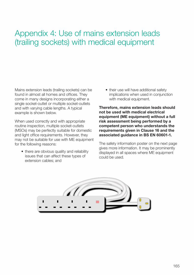
165
Appendix 4: Use of mains extension leads (trailing sockets) with medical equipment
Mains extension leads (trailing sockets) can be found in almost all homes and offices. They come in many designs incorporating either a single socket-outlet or multiple socket-outlets and with varying cable lengths. A typical example is shown below.
When used correctly and with appropriate routine inspection, multiple socket-outlets (MSOs) may be perfectly suitable for domestic and light office requirements. However, they may not be suitable for use with ME equipment for the following reasons:
• there are obvious quality and reliability issues that can affect these types of extension cables; and
• their use will have additional safety implications when used in conjunction with medical equipment.
Therefore, mains extension leads should not be used with medical electrical equipment (ME equipment) without a full risk assessment being performed by a competent person who understands the requirements given in Clause 16 and the associated guidance in BS EN 60601-1.
The safety information poster on the next page gives more information. It may be prominently displayed in all spaces where ME equipment could be used.
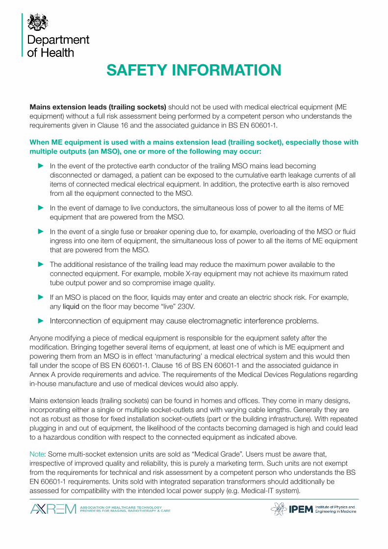
SAFETY INFORMATION
Mains extension leads (trailing sockets) should not be used with medical electrical equipment (ME equipment) without a full risk assessment being performed by a competent person who understands the requirements given in Clause 16 and the associated guidance in BS EN 60601-1.
When ME equipment is used with a mains extension lead (trailing socket), especially those with multiple outputs (an MSO), one or more of the following may occur:
In the event of the protective earth conductor of the trailing MSO mains lead becoming disconnected or damaged, a patient can be exposed to the cumulative earth leakage currents of all items of connected medical electrical equipment. In addition, the protective earth is also removed from all the equipment connected to the MSO.
In the event of damage to live conductors, the simultaneous loss of power to all the items of ME equipment that are powered from the MSO.
In the event of a single fuse or breaker opening due to, for example, overloading of the MSO or fluid ingress into one item of equipment, the simultaneous loss of power to all the items of ME equipment that are powered from the MSO.
The additional resistance of the trailing lead may reduce the maximum power available to the connected equipment. For example, mobile X-ray equipment may not achieve its maximum rated tube output power and so compromise image quality.
If an MSO is placed on the floor, liquids may enter and create an electric shock risk. For example, any liquid on the floor may become “live” 230V.
Interconnection of equipment may cause electromagnetic interference problems.
Anyone modifying a piece of medical equipment is responsible for the equipment safety after the modification. Bringing together several items of equipment, at least one of which is ME equipment and powering them from an MSO is in effect ‘manufacturing’ a medical electrical system and this would then fall under the scope of BS EN 60601-1. Clause 16 of BS EN 60601-1 and the associated guidance in Annex A provide requirements and advice. The requirements of the Medical Devices Regulations regarding in-house manufacture and use of medical devices would also apply.
Mains extension leads (trailing sockets) can be found in homes and offices. They come in many designs, incorporating either a single or multiple socket-outlets and with varying cable lengths. Generally they are not as robust as those for fixed installation socket-outlets (part or the building infrastructure). With repeated plugging in and out of equipment, the likelihood of the contacts becoming damaged is high and could lead to a hazardous condition with respect to the connected equipment as indicated above.
Note: Some multi-socket extension units are sold as “Medical Grade”. Users must be aware that, irrespective of improved quality and reliability, this is purely a marketing term. Such units are not exempt from the requirements for technical and risk assessment by a competent person who understands the BS EN 60601-1 requirements. Units sold with integrated separation transformers should additionally be assessed for compatibility with the intended local power supply (e.g. Medical-IT system).

References
167
References
Acts and Regulations
Note:
Only the primary Acts and main Regulations are cited here. Most of these Acts and Regulations have been subjected to amendment subsequent to the date of first becoming law. These amending Acts or Regulations are not included in this list.
Standards and other specification documents are continually being updated, and readers should ensure that they consult the latest editions of such documents, including any amendments issued after publication, to keep abreast of changing requirements.
Building Regulations 2010. SI 2010 No 2214.
Clean Air Act 1993. HMSO, 1993.
Construction (Design and Management) Regulations 2015. SI 2015 No 51. HMSO, 2015.
Control of Noise at Work Regulations 2005. SI 2005 No. 1643. HMSO, 2005.
Electricity at Work Regulations 1989. SI 1989 No 635. HMSO, 1989.
Electricity Safety, Quality and Continuity Regulations 2002. SI 2002 No 2665. HMSO, 2002.
Electromagnetic Compatibility Regulations 2006. SI 2005 No 281. HMSO, 2005.
Fluorinated Greenhouse Gases Regulations 2015. SI 2015 No. 310. HMSO, 2015.
Health and Safety at Work etc. Act 1974. HMSO, 1974.
Management of Health and Safety at Work Regulations 1999. SI 1999 No 3242. HMSO, 1999.
Medical Devices Regulations 2002. SI 2002 No. 618. HMSO, 2002.
Note:
The new Medical Devices Regulations are expected to come into force in May 2017. There may be a transition period for product standards identified in the legislation.
Radio Equipment and Telecommunications Terminal Equipment Regulations 2000. SI 2000 No 730.
British, European and International StandardsBS 88. Cartridge fuses for voltages up to and including 1000 V ac and 1500 V dc. Specification of supplementary requirements for fuse-links for use in ac electricity supply networks. British Standards Institution, 1988.
BS 4999-145:1987. General requirements for rotating electrical machines. Specification for winding terminations. British Standards Institution, 1987.

168
Health Technical Memorandum 06-01: Electrical services supply and distribution (2017 Edition)
BS 5266. Emergency lighting. British Standards Institution, 2016.
BS 5733:2010+A1:2014. General requirements for electrical accessories. Specification. British Standards Institution, 2014.
BS 5839-1:2013. Fire detection and fire alarm systems for buildings. Code of practice for design, installation, commissioning and maintenance of systems in non-domestic premises. British Standards Institution, 2013.
BS 6423:2014. Code of practice for maintenance of low-voltage switchgear and controlgear. British Standards Institution, 2014.
BS 6626:2010. Maintenance of electrical switchgear and controlgear for voltages above 1 kV and up to and including 36 kV. Code of practice. British Standards Institution, 2013.
BS 6701:2016. Telecommunications equipment and telecommunications cabling. Specification for installation, operation and maintenance. British Standards Institution, 2016.
BS 7430:2011+A1:2015. Code of practice for protective earthing of electrical installations. British Standards Institution, 2015.
BS 7594:2011. Code of practice for audio-frequency induction-loop systems (AFILS). British Standards Institution, 2011.
BS 7671:2008+A3:2015. Requirements for electrical installations. IET Wiring Regulations. Seventeenth edition. Institution of Engineering and Technology/British Standards Institution, 2015.
BS 7698, ISO 8528. Reciprocating internal combustion engine driven alternating current generating sets. British Standards Institution, 1996–1999.
BS 8488:2009+A1:2010. Prefabricated wiring systems intended for permanent connection in fixed installations. Specification. British Standards Institution, 2010.
BS 8519:2010. Selection and installation of fire-resistant power and control cable systems for life safety and fire-fighting applications. Code of practice. British Standards Institution, 2010.
BS 9999. Code of practice for fire safety in the design, management and use of buildings. British Standards Institution, 2008.
BS EN 81. Safety rules for the construction and installation of lifts. British Standards Institution, 1998–2003.
Note:
BS EN 81-1 has been superseded by BS EN 81-20 and BS EN 81-50 (see below) although there is a period of grace as BS EN 81-1 will not be withdrawn until the end of August 2017. See Health Technical Memorandum 08-02 – ‘Lifts’ for further clarification.
BS EN 81-20:2014. Safety rules for the construction and installation of lifts. Lifts for the transport of persons and goods. Passenger and goods passenger lifts. British Standards Institution, 2014.
BS EN 81-50:2014. Safety rules for the construction and installation of lifts. Examinations and tests. Design rules, calculations, examinations and tests of lift components. British Standards Institution, 2014.
BS EN 547-1:1996+A1:2008. Safety of machinery. Human body measurements. Principles for determining the dimensions required for openings for whole body access into machinery. British Standards Institution, 2008.
BS EN 547-2:1996+A1:2008. Safety of machinery. Human body measurements. Principles for determining the dimensions required for access openings. British Standards Institution, 2008.

References
169
BS EN 547-3:1996+A1:2008. Safety of machinery. Human body measurements. Anthropometric data. British Standards Institution, 2008.
BS EN 1838:2013. Lighting applications. Emergency lighting. British Standards Institution, 2013.
BS EN 12464-1:2011. Light and lighting. Lighting of work places. Indoor work places. British Standards Institution, 2011.
BS EN 50085-1:2005+A1:2013. Cable trunking systems and cable ducting systems for electrical installations. General requirements. British Standards Institution, 2013.
BS EN 50174-1:2009+A2:2014. Information technology. Cabling installation. Specification and quality assurance. British Standards Institution, 2001.
BS EN 50174-2: 2009+A2:2014. Information technology. Cabling installation. Installation planning and practices inside buildings. British Standards Institution, 2001.
BS EN 50174-3:2013. Information technology. Cabling installation. Installation planning and practices outside buildings. British Standards Institution, 2013.
BS EN 50310:2016. Telecommunications bonding networks for buildings and other structures. British Standards Institution, 2006.
BS EN 50464-3. Three-phase oil-immersed distribution transformers, 50 Hz, from 50 to 2500 kVA with highest voltage for equipment not exceeding 36 kV. Determination of the power rating of a transformer loaded with non-sinusoidal currents. British Standards Institution, 2007.
BS EN 50522:2010. Earthing of power installations exceeding 1 kV a.c. British Standards Institution, 2012.
BS EN 60034-2-1:2014. Rotating electrical machines. Standard methods for determining
losses and efficiency from tests (excluding machines for traction vehicles). British Standards Institution, 2014.
BS EN 60076. Power transformers. British Standards Institution, 2011–2015.
BS EN 60118-4:2015. Electroacoustics. Hearing aids. Induction-loop systems for hearing aid purposes. System performance requirements. British Standards Institution, 2015.
BS EN 60146-1-1:2010. Semiconductor convertors. General requirements and line commutated convertors. Specification of basic requirements. British Standards Institution, 2010.
BS EN 60270:2001+A1:2016. High-voltage test techniques. Partial discharge measurements. British Standards Institution, 2016.
BS EN 60309-1:1999+A2:2012, IEC 60309-1:1999. Plugs, socket-outlets and couplers for industrial purposes. General requirements. British Standards Institution, 1999.
BS EN 60422:2013. Mineral insulating oils in electrical equipment. Supervision and maintenance guidance. British Standards Institution, 2013.
BS EN 60601-1:2006+A12:2014. Medical electrical equipment. General requirements for basic safety and essential performance. British Standards Institution, 2014.
BS EN 60601-1-2:2015. Medical electrical equipment. General requirements for basic safety and essential performance. Electromagnetic disturbances. Requirements and tests. British Standards Institution, 2015.
BS EN 60896-21 2004. Stationary lead-acid batteries. Valve regulated types. Methods of test. British Standards Institution, 2004.

170
Health Technical Memorandum 06-01: Electrical services supply and distribution (2017 Edition)
BS EN 60896-22 2004. Stationary lead-acid batteries. Valve regulated types. Requirements. British Standards Institution, 2004.
BS EN 61008-1:2012+A11:2015. Residual current operated circuit-breakers without integral overcurrent protection for household and similar uses (RCCBs). General rules. British Standards Institution, 2015.
BS EN 61009-1:2012+A12:2016. Residual current operated circuit-breakers with integral overcurrent protection for household and similar uses (RCBOs). General rules. British Standards Institution, 2015.
BS EN 61386-1:2008. Conduit systems for cable management. General requirements. British Standards Institution, 2009.
BS EN 61439-1:2011. Low-voltage switchgear and controlgear assemblies. General rules. British Standards Institution, 2011
BS EN 61439-2:2011. Low-voltage switchgear and controlgear assemblies. Power switchgear and controlgear assemblies. British Standards Institution, 2011.
BS EN 61439-3:2012. Low-voltage switchgear and controlgear assemblies. Distribution boards intended to be operated by ordinary persons (DBO). British Standards Institution, 2012.
BS EN 61439-6:2012. Low-voltage switchgear and controlgear assemblies. Busbar trunking systems (busways). British Standards Institution, 2011.
BS EN 61508-1:2010. Functional safety of electrical/electronic/ programmable electronic safety-related systems. General requirements. British Standards Institution, 2010.
BS EN 61508-2:2010. Functional safety of electrical/electronic/ programmable electronic safety-related systems. Requirements for electrical/electronic/ programmable electronic safety-related systems. British Standards Institution, 2010.
BS EN 61508-3:2010. Functional safety of electrical/electronic/ programmable electronic safety-related systems. Software requirements. British Standards Institution, 2010.
BS EN 61535:2009+A1:2013. Installation couplers intended for permanent connection in fixed installations. British Standards Institution, 2013.
BS EN 61557-9:2015. Electrical safety in low voltage distribution systems up to 1 000 V a.c. and 1 500 V d.c. Equipment for testing, measuring or monitoring of protective measures. Equipment for insulation fault location in IT systems. British Standards Institution, 2015.
BS EN 61558-2-15:2012. Safety of transformers, reactors, power supply units and combinations thereof. Particular requirements and tests for isolating transformers for the supply of medical locations. British Standards Institution, 2009.
BS EN 61643-11:2012. Low-voltage surge protective devices. Surge protective devices connected to low-voltage power systems. Requirements and test methods. British Standards Institution, 2012.
BS EN 61936-1:2010+A1:2014. Power installations exceeding 1 kV a.c. Common rules. British Standards Institution, 2012.
BS EN 62040-1:2008+A1:2013. Uninterruptible power systems (UPS). General and safety requirements for UPS. British Standards Institution, 2013.
BS EN 62040-2:2006. Uninterruptible power systems (UPS). Electromagnetic compatibility (EMC) requirements. British Standards Institution, 2006.
BS EN 62271-202:2014. High-voltage switchgear and controlgear. High-voltage/low-voltage prefabricated substation. British Standards Institution, 2014.

References
171
BS EN 62305-1:2011. Protection against lightning. General principles. British Standards Institution, 2011.
BS EN 62305-2:2012. Protection against lightning. Risk management. British Standards Institution, 2012.
BS EN 62305-3:2011. Protection against lightning. Physical damage to structures and life hazard. British Standards Institution, 2011.
BS EN 62305-4:2011. Protection against lightning. Electrical and electronic systems within structures. British Standards Institution, 2011.
BS EN 62353:2014. Medical electrical equipment. Recurrent test and test after repair of medical electrical equipment. British Standards Institution, 2013.
BS EN 62423:2012. Type F and type B residual current operated circuit-breakers with and without integral overcurrent protection for household and similar uses. British Standards Institution, 2012.
BS EN 62561-2:2012. Lightning Protection System Components (LPSC). Requirements for conductors and earth electrodes. British Standards Institution, 2011.
BS EN 62680-1-1:2015. Universal Serial Bus interfaces for data and power. Universal Serial Bus interfaces. Common components. USB Battery Charging Specification, Revision 1.2 (TA 14). British Standards Institution, 2015.
BS EN 62684:2010. Interoperability specifications of common external power supply (EPS) for use with data-enabled mobile telephones. British Standards Institution, 2011.
BS EN ISO 9001:2015. Quality management systems. Requirements. British Standards Institution, 2016.
BS EN ISO 11197:2016. Medical supply units. British Standards Institution, 2016.
BS EN ISO/IEC 17050-1:2010. Conformity assessment. Supplier’s declaration of conformity. General requirements. British Standards Institution, 2010.
BS IEC 61000-5-2:1997. Electromagnetic compatibility (EMC). Installation and mitigation guidelines. Earthing and cabling. British Standards Institution, 1997.
BS ISO 3046. Reciprocating internal combustion engines. British Standards Institution, 2001–2009.
IEC 60269-1:2006. Low-voltage fuses – Part 1: General requirements. International Electrotechnical Committee, 2006.
IEC 60282-1:2009. High-voltage fuses – Part 1: Current-limiting fuses. International Electrotechnical Committee, 2009.
Department of Health publicationsHealth Building Note 00-03 – Clinical and clinical support spaces. 2013.
Health Building Note 00-07 – Planning for a resilient healthcare estate. 2014.
Health Technical Memorandum 00 – Policies and principles of healthcare engineering. 2014.
Health Technical Memorandum 02-01 – Medical gas pipeline systems. 2005.
Health Technical Memorandum 05-02 (Firecode) – Fire safety in the design of healthcare premises. 2015.
Health Technical Memorandum 05-03 (Firecode) – Part B. Fire detection and alarm systems. 2006.
Health Technical Memorandum 06-02 – Electrical safety guidance for low voltage systems. 2006.
Health Technical Memorandum 06-03 – Electrical safety guidance for high voltage systems. 2006.

172
Health Technical Memorandum 06-01: Electrical services supply and distribution (2017 Edition)
Health Technical Memorandum 07-02 (Encode) – Making energy work in healthcare. 2015.
Health Technical Memorandum 08-02 – Lifts. 2016.
Health Technical Memorandum 08-03 – Bedhead services. 2013
NHS Premises Assurance Model.
Miscellaneous publicationsBEAMA (2011). Guide to forms of separation: low voltage switchgear and controlgear assemblies to BS EN 61439-2. BEAMA Limited, London.
BSRIA (2011). BG 9: Rules of Thumb – guidelines for building services. BSRIA, Bracknell.
CIBSE (2001). CCC Commissioning Code C: Automatic controls. CIBSE, London.
CIBSE (2003). CCL Commissioning Code L: Lighting. CIBSE, London.
CIBSE (2003). CCM Commissioning Code M: Commissioning management. CIBSE, London.
CIBSE (2005). Guide K: Electricity in buildings. CIBSE, London.
CIBSE (2006). Technical memorandum TM22: Energy assessment and reporting methodology. CIBSE, London.
CIBSE (2006). Technical memorandum TM31: Building log book toolkit. CIBSE, London.
CIBSE (2008). Lighting Guide 2 LG2: Hospitals and health care buildings. CIBSE, London.
CIBSE (2008). Technical memorandum TM46: Energy benchmarks. CIBSE, London.
CIBSE (2012). GVF2012 Guide F: Energy efficiency in buildings. CIBSE, London.
Committee on Climate Change (2017). UK Climate Change Risk Assessment 2017: Synthesis report – priorities for the next five years. Committee on Climate Change, London.
Department for Communities and Local Government (DCLG) (2007). Approved Document B. Fire safety. Volume 2 – buildings other than dwellinghouses.
Energy Networks Association (1995). Engineering Technical Report ETR 113: Notes of guidance for the protection of embedded generating plant up to 5MW for operation in parallel with public electricity suppliers distribution systems (revision 1). ENA, London.
Energy Networks Association (2002). Engineering Recommendation G.75/1: Recommendations for the connection of embedded generating plant to public distribution systems above 20 kV or with outputs over 5MW. ENA, London.
Energy Networks Association (2003). Engineering Recommendation G.83/1: Recommendations for the connection of small-scale embedded generators (up to 16A per phase) in parallel with public low-voltage distribution networks. ENA, London.
Energy Networks Association (2005). Engineering Recommendation G5/4-1: Planning levels for harmonic voltage distortion and the connection of non-linear equipment to transmission systems and distribution networks in the UK. ENA, London.
Energy Networks Association (2005). Engineering Recommendation G.84: Recommendations for the connection of mobile generating sets to public distribution networks. ENA, London.

References
173
Energy Networks Association (2015). Engineering Recommendation G.59/3-2: Recommendations for the connection of generating plant to the distribution systems of licensed distribution network operators. ENA, 2015.
Health & Safety Executive (2013). HSG85: Electricity at work: safe working practices. HSE Books.
Health & Safety Executive (2013). HSG107: Maintaining portable electrical equipment. HSE Books.
Health & Safety Executive (2013). INDG372: electrical switchgear safety: guide for owners and users. HSE Books.
Health & Safety Executive (2015). HSG230: keeping electrical switchgear safe. HSE Books.
Health & Safety Executive (2015). HSR25: The Electricity at Work Regulations 1989: guidance on regulations. HSE Books.
Institution of Engineering and Technology (IET) (2012). Code of practice for in-service
inspection and testing of electrical equipment (4th Edition). IET, Stevenage.
Institution of Engineering and Technology (IET) (2015). Code of practice for grid connected solar photovoltaic systems. IET, Stevenage.
Institution of Engineering and Technology (IET) (2015). Guidance Note 1: Selection and erection (7th Edition). IET, Stevenage.
Institution of Engineering and Technology (IET) (2012). Guidance Note 3: Inspection & Testing (7th Edition). IET, Stevenage.
Institution of Engineering and Technology (IET) (2015). Guidance Note 7: Special locations (4th Edition). IET, Stevenage.
Ministry of Defence (1996). Defence Works Functional Standard DMG 08 – Space requirements for plant access, operation and maintenance. The Stationery Office, 1996.
UK Power Networks (2013). Engineering design standard EDS 05-4001. Fuse ratings at distribution substations.