hdpe flange adapter - amazon s3 · pdf filehdpe flange adapter ... each coupling uses two...
TRANSCRIPT
GL-7.16
PROJECT INFORMATION APPROVAL STAMPProject: q Approved
Address: q Approved as noted
Contractor: q Not approved
Engineer: Remarks:
Submittal Date:
Notes 1:
Notes 2:
HDPE COUPLINGS
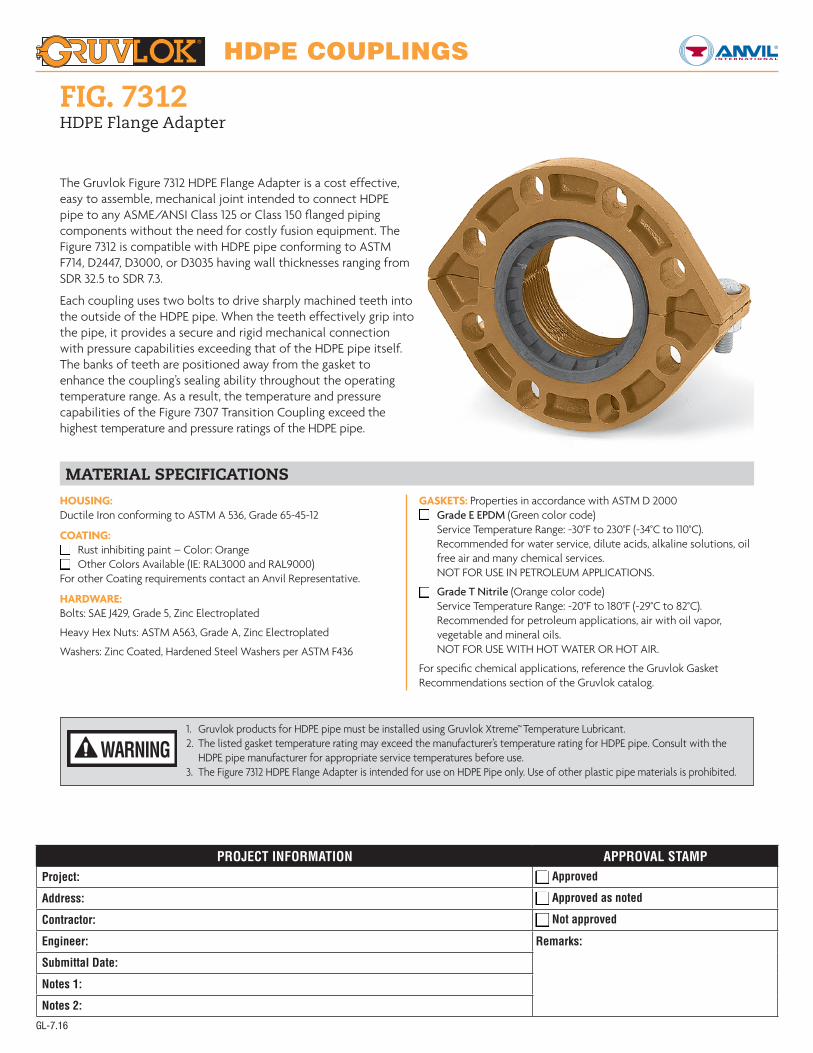
FIG. 7312HDPE Flange Adapter
The Gruvlok Figure 7312 HDPE Flange Adapter is a cost effective, easy to assemble, mechanical joint intended to connect HDPE pipe to any ASME/ANSI Class 125 or Class 150 flanged piping components without the need for costly fusion equipment. The Figure 7312 is compatible with HDPE pipe conforming to ASTM F714, D2447, D3000, or D3035 having wall thicknesses ranging from SDR 32.5 to SDR 7.3.
Each coupling uses two bolts to drive sharply machined teeth into the outside of the HDPE pipe. When the teeth effectively grip into the pipe, it provides a secure and rigid mechanical connection with pressure capabilities exceeding that of the HDPE pipe itself. The banks of teeth are positioned away from the gasket to enhance the coupling’s sealing ability throughout the operating temperature range. As a result, the temperature and pressure capabilities of the Figure 7307 Transition Coupling exceed the highest temperature and pressure ratings of the HDPE pipe.
MATERIAL SPECIFICATIONSHOUSING: Ductile Iron conforming to ASTM A 536, Grade 65-45-12
COATING:q Rust inhibiting paint – Color: Orangeq Other Colors Available (IE: RAL3000 and RAL9000)For other Coating requirements contact an Anvil Representative.
HARDWARE: Bolts: SAE J429, Grade 5, Zinc Electroplated
Heavy Hex Nuts: ASTM A563, Grade A, Zinc Electroplated
Washers: Zinc Coated, Hardened Steel Washers per ASTM F436
GASKETS: Properties in accordance with ASTM D 2000q Grade E EPDM (Green color code)
Service Temperature Range: -30°F to 230°F (-34°C to 110°C). Recommended for water service, dilute acids, alkaline solutions, oil free air and many chemical services. NOT FOR USE IN PETROLEUM APPLICATIONS.
q Grade T Nitrile (Orange color code) Service Temperature Range: -20°F to 180°F (-29°C to 82°C). Recommended for petroleum applications, air with oil vapor, vegetable and mineral oils. NOT FOR USE WITH HOT WATER OR HOT AIR.
For specific chemical applications, reference the Gruvlok Gasket Recommendations section of the Gruvlok catalog.
1. Gruvlok products for HDPE pipe must be installed using Gruvlok Xtreme™ Temperature Lubricant.2. The listed gasket temperature rating may exceed the manufacturer’s temperature rating for HDPE pipe. Consult with the HDPE pipe manufacturer for appropriate service temperatures before use.3. The Figure 7312 HDPE Flange Adapter is intended for use on HDPE Pipe only. Use of other plastic pipe materials is prohibited.
WARNING

HDPE COUPLINGS
GL-9.15
FIG. 7312HDPE Flange Adapter
1. When mating to a wafer valve (lug valve), if the valve is rubber faced in the area designated by the sealing surface dimensions (A Max. to B Min.), place the Gruvlok Flange Adapter Insert between the valve and the Gruvlok Flange.
2. When mating to a rubber-faced metal flange, the Gruvlok Flange Adapter Insert is placed between the Gruvlok Flange and the rubber-faced flange.
3. When mating to a serrated flange surface, a standard fullfaced flange gasket is installed against the serrated flange face, and the Gruvlok Flange Adapter Insert is placed between the Gruvlok Flange and the standard flange gasket.
4. When mating to valves or other component equipment where the flange face has an insert, use procedure described in note 3.
APPLICATIONS WHICH REQUIRE A GRUVLOK® FLANGE ADAPTER INSERT:
A. The sealing surfaces A Max. to B Min. of the mating flange must be free from gouges, undulations and deformities of any type to ensure proper sealing of gasket.
B. Gruvlok Flanges are to be assembled on butterfly valves so as not to interfere with actuator or handle operation.
C. Do not use Gruvlok Flanges within 90 degrees of one another on standard fittings because the outside dimensions may cause interference.
D. Gruvlok Flanges should not be used as anchor points for tierods across non-restrained joints.
E. Fig. 7312 Gruvlok Flange sealing gaskets require a hard flat surface for adequate sealing. The use of a Gruvlok Flange Adapter Insert is required for applications against rubber faced valves or other equipment. The Gruvlok Flange Adapter Insert is installed between the Gruvlok Flange sealing gasket and the mating flange or surface to provide a good sealing surface area.
F. Gruvlok Flanges are not recommended for use against formed rubber flanges.
G. The pressure rating of the Figure 7307 HDPE Transition Coupling is determined by the working pressure of the HDPE pipe installed. Consult with the HDPE pipe manufacturer for the appropriate working pressure before use. HDPE working pressures are determined by wall thickness, pipe composition, and applicable service temperature.
FIGURE 7312 HDPE FLANGE ADAPTER
Nominal Size Pipe O.D.
Flange Dimensions Sealing Surface Latch Bolt Mating Flange Bolts Approx. Wt. Ea.X Y Z A Max. B Min. Qty. Size Qty. Size
In./DN(mm) In./DN(mm) In./mm In./mm In./mm In./mm In./mm In. In./mm Lbs./Kg
4 4.500 87⁄8 101⁄4 3 45⁄8 53⁄82 5⁄8 x 2 8 5⁄8 x 3 12
100 114.3 225 260 76 117 137 5.4
6 6.625 111⁄8 121⁄4 31⁄2 63⁄4 75⁄82 3⁄4 x 31⁄2 8 3⁄4 x 31⁄2
18150 168.3 283 311 89 171 194 8.2
8 8.625 131⁄2 143⁄4 31⁄2 83⁄4 97⁄82 3⁄4 x 31⁄2 8 3⁄4 x 31⁄2
30200 219.1 343 375 89 222 251 13.6
HDPE PIPE DIMENSIONAL SPECIFICATIONS
Nominal Size Pipe O.D. O.D. Tolerance
+/-Out of Roundness
Tolerance +/-
Pipe Wall Thickness
SDR 7.3 SDR 9 SDR 11 SDR 15.5 SDR 17 SDR 21 SDR 32.5In./DN(mm) In./mm In./mm In./mm In./mm In./mm In./mm In./mm In./mm In./mm In./mm
4 4.500 0.020 0.040 0.616 0.500 0.409 0.290 0.265 0.214 0.138100 114.3 0.51 1.02 15.6 12.7 10.4 7.4 6.7 5.4 3.5
6 6.625 0.030 0.050 0.908 0.736 0.602 0.427 0.327 0.265 0.204150 168.3 0.76 1.27 23.1 18.7 15.3 10.8 8.3 6.7 5.2
8 8.625 0.039 0.075 1.182 0.958 0.784 0.556 0.507 0.340 0.265200 219.1 0.99 1.91 30.0 24.3 19.9 14.1 12.9 8.6 6.7
HDPE Pipe Dimensions per ASTM F714, ASTM D2447, and ASTM D3035See Installation & Assembly directions on next page.
Y Z
X
Gruvlok Fig.7312 Flange
Gruvlok Fig.7312 Flange
Serrated FaceMating Flange
FlangeGasket
Mating FlangeComponent
Grooved Pipe Grooved PipeRubber SurfaceGruvlok Flange Adapter Insert
Gruvlok Flange Adapter InsertB min.A max.
NOTE A NOTES 1 and 2 NOTES 3 and 4

HDPE COUPLINGS
GL-9.15
FIG. 7312HDPE Flange Adapter
1PIPE PREPARATION— Ensure the HDPE pipe ends are square cut to 1/8"
maximum for 2" to 4" sizes and 5/32" maximum for 6" sizes and larger. Inspect the surface of the mating flange to ensure the gasket seating surface is clean and smooth for proper gasket sealing.
3 HOUSING— Place the housing over the end of the pipe and using a straight edge,
align the face and the flange face with the end of the pipe. Do not let the pipe extend beyond the flange face.
4 LATCH HOUSING— Tighten the housing nut until the housing bolt pads
make firm metal to metal contact. Torque all bolts to the required latch bolt torque levels. Refer to the Specified Latch Bolt Torque Table.
5 INSTALL GASKET— Position the Gruvlok Flange gasket around the pipe end
and press the gasket into the flange gasket pocket. Be sure the flange sealing lips are facing out.
6ALIGN PIPE— Align the Gruvlok Flange bolt holes with the mating flange bolt holes.
Insert a standard bolt or stud through one bolt hole and thread the nut on hand tight. Insert the next bolt or stud opposite the first and thread the nut on hand tight. Continue this procedure until all holes have been fitted.
7 TIGHTEN BOLTS— Tighten the flange face nuts alternately and evenly so that
the flange faces remain parallel and make firm contact around the entire flange. Torque all bolts to the required mating flange joint torque levels. Refer to the Specified Mating Flange Bolt Torque Table.
SPECIFIED BOLT TORQUE FOR LATCH & MATING FLANGE BOLTS
Specified bolt torque is for the latch and mating flange bolts used on Gruvlok® flanges. The nuts must be tightened alternately and evenly until fully tightened.
FIG. 7312 LATCH BOLT TORQUE
Coupling Bolts Minimum Maximum
In. Ft.-Lbs./N-m Ft.-Lbs./N-m
5⁄8 X 2 100 130135 175
3⁄4 X 31⁄2 130 180175 245
FIG. 7312 MATING FLANGE BOLT TORQUE
Coupling Bolts Minimum Maximum
In. Ft.-Lbs./N-m Ft.-Lbs./N-m
5⁄8 X 3 110 140149 190
3⁄4 X 31/2220 250298 339
CAUTION: For proper coupling performance, the gasket seating surfaces must be free of scratches, indentations, projections, or other imperfections that could prevent proper sealing of the gasket.
2 CHECK & LUBRICATE GASKET—Check to assure the gasket material is
acceptable for the intended service. The gasket color code is green for EPDM and orange for Nitrile (Buna-N).
CAUTION: Use only Gruvlok Xtreme™ Lubricant. Gruvlok Xtreme Lubricant contains silicone. If silicone is unacceptable for the application contact Gruvlok for the lubrication recommendation. Apply a thin coating of Gruvlok Xtreme Lubricant to the gasket lip and the exterior surface of the gasket.
CAUTION: For proper performance, the Figure 7312 HDPE Flange adapter should always be installed with the housing bolt pads making metal to metal contact.
CAUTION: Take care to assure the gasket lip is not bent backwards and pinched between the two flanges.
CAUTION: Proper torquing of latch and mating flange bolts is required to obtain specified performance.Over torquing the bolts may result in damage to the bolt and/or casting which could result in pipe joint separation. Under torquing the bolts may result in lower pressure retention capabilities, lower bend load capabilities, joint leakage and pipe joint separation. Pipe joint separation may result in significant property damage and serious injury.
CAUTION: Use of an impact wrench is not recommended because the torque output can vary significantly due to many variables including air pressure supply, battery strength and operational variations.