hc--278h ii - link-belt construction equipment
TRANSCRIPT

15444---0205---M2
HC---278H IILink-Belt Cranes
Technical DataSpecifications & Tube Boom Capacities
HC--278H IITruck Crane
300 Ton (272 metric ton)
CAUTION: Thismaterial is supplied for referenceuseonly. Operator must refer to in---cab Crane RatingManual and Operator’s Manual to determineallowable crane lifting capacities and assembly andoperating procedures.

5444---0205---M2
HC---278H II Link-Belt Cranes

15444---0205---M2
HC---278H IILink-Belt Cranes
Table Of ContentsPages
Specifications 1--12Tube Boom Capacities 1--20Tube Boom + Jib Capacities 1--16

5444---0205---M2
HC---278H II Link-Belt Cranes
This page intentionally left blank

SpecificationsLattice Boom Truck Crane
HC–278H II 300–ton (272 metric ton)
HYLAB Series
5’ 10”(1.78m)
38” (0.97m)
��� ���
General Dimensions English Metric
Overall width, outriggers extended (over pontoons) 27’ 4” 8.33mOverall width, outriggers extended (c/l of pontoons) 24’ 6” 7.46mOverall width, outriggers retracted, jacks removed 11’ 10” 3.61m
Vehicle clearance circle over outside of front bumper 122’ 10” 37.44mVehicle clearance circle over outside of front bumper ctwt. 125’ 10” 38.35mMinimum ground clearance (at bottom of front bogie beams) 8.88” 0.22mCounterweight tailswing (at corners) 18’ 9” 5.69m
Overall width (upper) 11’ 10” 3.61mRadius of boom foot pin 3’ 2” 0.97mHeight of boom foot pin 7’ 3.38” 2.22mGround clearance under counterweight 5’ 5.38” 1.65m
R
������������
27’ 4” (8.33m)24’ 6” (7.46m)
11’ 10”(3.61m)
35” (0.86m)
14’ 3.75”(4.36m)
43’ 8”(13.31m)
82�
8’ 9”(2.66m)
60’(18.29m)
9’ 2.25”(2.80m)
rear
9’ 7”(2.92m)
front
13’ 11.25”(4.25m)
12’ 3” (3.73m)
12’ 3” (3.73m)
13’ 9.3” (4.20m)
45’ 11.5” (14.01m)
19’ 7.3” (5.98m)
29’ 3” (8.92m)
32’ 2.2” (9.81m)
��
7’ 11.38”(2.42m)

HC–278H II – 2 –
HC–278H II Crane Transport Weights and Dimensions – approximate
25”(0.64m)
25”(0.64m)
53.44”(1.38m)
9.62”(0.24m)
2’ 1.5”(0.65m)
13’ 6”(4.11m)
19’ 7.75”(5.97m)
24’ 2”(7.36m)
68’ 9.75”(20.97m)
28’ 1.75”(8.58m)
68’ 9.75”(20.97m)
9.62”(0.24m)
53.44”(1.38m)
33’ 3.5”(10.14m)
73’ 11.5”(22.54m)
13’ 6”(4.11m)
13’ 6”(4.11m)
Note: Blocking presentbetween load and trailer.
Transport Weightswithout boom base – 168,824 lb (76 577kg)
with boom base – 173,736 lb (78 805kg)with boom base and 10 ft self–assembly section – 177,011 lb (80 291kg)
Transport Weightswithout boom base – 76,976 lb (34 916kg)
with boom base – 83,173 lb (37 727kg)with boom base and 10 ft self–assembly section – 84,757 lb (38 446kg)
Transport Weightswith hammerhead and transition section and head machinery – 86,996 lb (39 461kg)
Note: Blocking presentbetween load and trailer.
Note: Carrier undecked with outrigger boxes and without jacks = 70,500 lb (31 978kg)
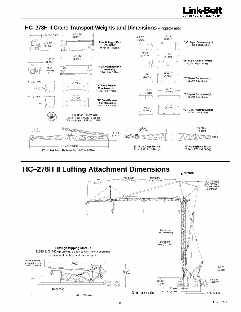
HC–278H II– 3 –
“B” Upper Counterweight25,000 lb (11 340kg)
“E ” Upper Counterweight10,000 lb (4 535kg)
“A” Upper Counterweight30,000 lb (13 607kg)
Rear Outrigger BoxAssembly
9,954 lb (4 515kg)
Front Outrigger BoxAssembly
9,048 lb (4 104kg)
10’ 11.5”(3.34m)
10’ 11.5”(3.34m)
3’ 9” (1.14m)
4’ 1.25”(1.25m)
3’ 10.5”(1.18m)
3’ 3”(0.99m)
“A” Front BumperCounterweight
11,400 lb (5 171kg)2’ 6” (0.76m)
11’ 10”(3.35m)
1’ 2” (0.45m)
HC–278H II Crane Transport Weights and Dimensions – approximate
30’ (9.14m) Basic Jib Assembly 1,900 lb (862kg)
31’ 7.5” (9.64m)
2’ 5”(0.74m) 6’ 3.5”
(1.92m)
30’ (9.14m) Base SectionTube: 4,772 lb (2 165kg)
30’ (9.14m) Top SectionTube: 5,321 lb (2 414kg)
32’ 11”(10.03m)
30’ 10.5”(9.41m)
“D” Upper Counterweight21,500 lb (9 752kg)
“C” Upper Counterweight21,500 lb (9 752kg)
“B” Front BumperCounterweight
15,300 lb (6 940kg)2’ 6” (0.76m)
11’ 10”(3.35m)
1’ 5” (0.45m)
18”(0.46m)
19.5”(0.50m)
9.88”(0.25m)
11’ 7”(3.53m)
11’ 3”(3.43m)
11’ 6.75”(3.52m)
49.25”(1.25m)
11’ 10”(3.61m)
11’ 10”(3.61m)
49.25”(1.25m)
Third Drum Rope WinchWith Rope: 4,772 lb (2 165kg)
Without Rope: 2,832 lb (1 285kg)
Minimum110’ (33.53m)
30’(9.14m)
Minimum90’ (27.43m)
Maximum200’ (60.96m) 22’ 2” (6.76m)
max distancefrom centerline
of rotation
3’ (0.9m)19’ 7.25” (5.98m) 23’ 6” (7.17m)
34’ 5”(10.5m)
12’ 11”(3.95m)
������������
14’ 3.75”(4.36m)
Maximum200’ (60.96m)
13” (0.33m)
47’ 11” (14.6m)
11’ 8”(3.5m)
26’ 0”(7.9m)
Luffing Shipping Module8,250 lb (3 742kg) Luffing jib base section, luffing boom top
section, and the front and rear fan post.
Note: Blockingpresent betweenload and trailer.
Not to scale
HC–278H II Luffing Attachment Dimensions

HC–278H II – 4 –
HC–278H II Luffing Attachment Nomenclature
PENDANT DEFLECTOR
FIXED JIB
FIXED JIB STRUT
LUFFING JIB
LUFFING JIBBACKSTOP
LUFFING BOOM
LUFFING BOOMLIVE MAST
LUFFING BOOMBACKSTOP
LUFFING BOOMBRIDLE
LUFFING BOOM BAIL
10’ SELF–ASSEMBLYSECTION
3RD DRUM
5’ BAIL ANCHORSECTION
10’ “JN” LUFFINGBOOM EXTENSION
LUFFING JIB BRIDLELUFFING JIB BAIL
FANPOST
AUXILIARY SHEAVES
MIDFALL EXTENSION
“ABCDE” UPPERCOUNTERWEIGHTS
“AB” LOWERCOUNTERWEIGHTS

HC–278H II– 5 –
HC–278H II Transportation Weights – approximateBase Crane: 85 gal (321L) of carrier fuel, live mast, 30’ boom base section,10’ self–assembly section, 12–part boom hoist reeving, rigid boom backstops, auxiliary lifting bail, 950’ (290m) front hoist rope, 600’ (182.88m) rear hoist rope, and 77 gal (291L of upper fuel.
Gross Weight Transport LoadsItem Description
lb kg #1 #2 #3 #4 #5 #6 #7 #8 #9Base Crane 76,976 34 916 1Carrier 70,500 31 978 1 Notes and Load Add Front Outrigger Assembly 10,560 4 790 1
Notes and Load Summary
Add Rear Outrigger Assembly 10,560 4 790 1Add Main Outrigger Jacks And Pontoons 5,060 2 295 1 Numbers in the load columns to
Add Front Outrigger Pontoon 80 36 1 the left represent quantities.
Add “A” Bumper Counterweight 11,400 5 171 1Add “B” Bumper Counterweight 15,300 6 940 1
Estimated transport assumes theload out consist of 330’ (100.58m)
Add “A” Upper Counterweight 30,000 13 607 1load out consist of 330’ (100.58m)of tube boom + 30’ (9.14m) of jib
Add “B” Upper Counterweight 25,200 11 430 1with full counterweight.
Add “C” Upper Counterweight 21,500 9 752 1 Loads were estimated for a 8’ 6”(2.6m) wide, 48’ (14.6m) long, and
Add “D” Upper Counterweight 21,500 9 752 1(2.6m) wide, 48’ (14.6m) long, and13’ 6” (4.1m) high using a drop
Add “E” Upper Counterweight 10,000 4 536 1 deck trailer. This may vary depend-ing on state laws, empty truck/trail-
Add Upper Catwalk – Left Side 154 70ing on state laws, empty truck/trail-er weights, and style of trailer.
Remove 30’ (6.10m) Boom Base Section – 4,912 – 2 228 Estimated weights vary by +/– 2%.Add 30’ (9.14m) Boom Top Section 5,612 2 546 1
Estimated weights vary by +/– 2%.
Add 10’ (3.05m) “JN” Boom Extension W/Pins, Pendants, & Toller 1,584 719 1 Estimated Total Load #1
Remove 10’ (3.05m) “J” Boom Extension W/Lifting Sheaves, Pins,Pendants, & Roller – 3,275 – 1 486
70,500 lb (31 978kg)
Add 20’ (6.10m) “JE” Boom Extension W/Pins, Pendants, & Roller 2,524 1 145 1 1Estimated Total Load #2 76,976 lb (34 916kg)
Add 30’ (9.14m) “JE” Boom Extension W/Pins, Pendants, & Roller 3,464 1 571 1 Estimated Total Load #3Add 40’ (12.19m) “JE” Boom Extension W/Pins, Pendants, & Roller 4,609 2 091 1
Estimated Total Load #345,966 lb (20 850kg)
Add 50’ (15.24m) “JE” Boom Extension W/Pins, Pendants, & Roller 5,608 2 544 1 Estimated Total Load #4Add 10’ (3.05m) “HJ” Boom Extension W/Pins, Pendants, & Roller 1,382 627 1
Estimated Total Load #437,320 lb (16 928kg)
Add 20’ (6.10m) “HJ” Boom Extension W/Pins, Pendants, & Roller 2,163 981 1 Estimated Total Load #5Add 30’ (9.14m) “HJ” Boom Extension W/Pins, Pendants, & Roller 2,940 1 334 1
Estimated Total Load #544,889 lb (23 361kg)
Add 40’ (12.19m) “HJ” Boom Extension W/Pins, Pendants, & Roller 3,687 1 672 Estimated Total Load #6
Add 50’ (15.24m) “HJ” Boom Extension W/Pins, Pendants, & Roller 4,538 2 058 1 44,736 lb (20 292kg).
Add Auxiliary Tip Extension 980 445 Estimated Total Load #7
Add Third Drum Fleeting Sheave For Luffer To Boom Base Section 2,373 1 07611,596 lb (5 260kg)
Add Third Drum 3–Sheave Assembly To Boom Top Section W/O Rope 2,832 1 285 Estimated Total Load #8
Add 30’ (9.14m) Tubular Jib 2,180 990 14,583 lb (2 058kg)
Add 10’ (3.05m) Tubular Jib Extension 259 118 Estimated Total Load #915,103 lb (6 851kg)
Add 20’ (6.1m) Tubular Jib Extension 442 20115,103 lb (6 851kg)
Add Luffing Top Assembly 8,250 3 742
Add Hammerhead Top Section With 10’ Transition Section 5,520 2 504
Add Auxiliary Hammerhead Tip Extension 976 443
Add Jib Wire Rope 1” x 850’ Type “RB” 1,700 771
Add jib Wire Rope 1.125” x 850’ Type “RB” 2,125 964
Add Jib Wire Rope 1” x 1,210’ Type “RB” 2,420 1 098
Add Third Drum Wire Rope 1” x 970’ Type “RB” 1,940 880
Remove Front Drum Rope 1.12” x 1,084’ Type “LB” –2,537 –1 151
Remove Rear Drum Rope 1” x 850’ Type “RB” –1,700 –770
Remove Boom Hoist Rope 1” x 1,070’ Type “W” –1,010 –458
Add 15–ton (13.6mt) Hook Ball – Non Swivel or Swivel 1,400 635
Add 60–ton (54mt) 2–Sheave Hook Block 1,650 747
Add 150–ton (136mt) 6–Sheave Hook Block 3,525 1 599
Add 200–ton (181mt) 6–Sheave Hook Block 3,860 1 751 1Add 250–ton (227mt) 6–Sheave Hook Block 5,721 2 595

HC–278H II – 6 –
HC–278H II Crane Working WeightsOption Description
GrossWeightlb (kg)
Maximum GroundBearing Pressure
psi (kg/cm2)
1Base crane equipped with 60’ (18.28m) of tube boom, live mast, “ABCDE” counterweight, 1,026’ (312m) hoist rope,250–ton (227mt) hook block, 143 gal (541L) of upper fuel, 85 gal (321L) of carrier fuel, front and rear outriggerboxes with pontoons and fifth outrigger pontoon, and 200 lb (90.7kg) operator.
297,982(135 162)
152(10.69)
2 Option #1 plus “A” and “B” bumper counterweights and 270’ (82.3m) of boom extensions to obtain 330’ (100.58m) ofmain boom.
356,773(161 830)
167(11.74)
3 Option #2 plus 100’ (30.5m) of tubular jib, 15–ton (13.6mt) hook ball and jib rope – subtract 30’ (9.14m) of boomextension to obtain maximum 300’ + 100’ (91.4 + 30.5m) of main boom + jib.
359,813(163 208)
161(11.32)
4
Option #1 plus, remove 30’ (9.14m) and 250–ton (227mt) hook block. Add “AB” bumper counterweight, 10’ (3.05m)self–assembly section, 5’ (1.52m) bail anchor, 140’ (42.67m) “JE” boom, 10’ (3.05m) “JN” boom, 5’ (1.52m) luffingboom cap, fan post, pendant deflector, luffing jib base (with backstops), 160’ (48.77m) luffing jib extensions, luffing jibpeak (with nose wheel), luffing jib bail, luffing jib bridle, 60’ (18.29m) bridle guide rails, 660’ (201m) of 1” (25mm) type“DB” wire rope, and 15–ton (13.6mt) hook ball.
368,252(167 036)
179(12.58)
5Base crane equipped with 45’ (13.72m) of hammerhead boom, live mast, “ABCD” upper counterweight, 1026’(313m) front hoist rope, 150–ton (136mt) hook block, 143 gal (531L) of upper fuel, 85 gal (321.76L) of carrier fuel,front and rear outrigger boxes with pontoons and fifth outrigger pontoon, and 200 lb (90.7kg) operator.
268,750(121 903)
144(10.12)
Attachment Options� 60’ – 330’ (18.29–
100.58m) Tubular Boom
Basic Boom – 60’ (18.29m) two–piece designthat utilizes a 30’ (9.14m) base section and a30’ (9.14m) open throat top section within–line connecting pins on 80” (2.03m) wideand 68” (1.73m) deep centers.� 250–ton (227mt) maximum capacity� Max boom tip height of 333’ (101.5m)� Boom feet on 66” (1.67m) centers� 4.25” (10.80 cm) diameter chords� Lugs on base section to attach carrying links� Skywalk platform� Deflector roller on top section� Rigid sheave guards� Six 21” (0.53m) root diameter steel sheaves
mounted on sealed anti–friction bearings� Oil filled mechanical boom angle indicator
Boom Extensions – The following tableprovides the lengths available and thesuggested quantity to obtain maximumboom in 10’ (3.05m) increments. Midpointpendant connections are required at 140’(42.67m) for boom lengths 250’ (72.6m)and longer.
Tube BoomExtensions
Suggested Quantityfor Maximum Boom
JN type 10’ (3.05m) 1JE type 20’ (6.10m) 1JE type 30’ (9.14m) 1JE type 40’ (12.19m) 1JE type 50’ (15.24m) 1HJ type 10’ (3.05m) 1HJ type 20’ (6.10m) 1HJ type 30’ (9.14m) 1HJ type 40’ (12.19m) 0HJ type 50’ (15.24m) 1
� Deflector roller on top of each section� Two rollers on 40’ (12.19m) and 50’ (15.24m)
extensions� Appropriate length pendants� The optional 10’ (3.05m) extension with lifting
sheaves is used for self assembly/disassemblyinstead of using live mast and auxiliary liftingbail.
� 45’ – 245’ (13.72–74.68m) Hammer–Head Boom
Basic Boom – 45’ (13.72m) three–piecedesign that utilizes a 30’ (9.14m) base section,a 10’ (3.05m) taper section, and a 5’ (1.52m)hammer head top section. Taper section pinsto standard base section with in–lineconnecting pins on 80” (2.03m) wide and 68”(1.73m) deep centers.� 200–ton (181.4mt) maximum capacity� Maximum boom tip height is 243’ (74.07m)� 4.25 (10.80m) tubular “JE” wall chords� Lugs on base section to attach carrying links� Skywalk platform� Deflector roller on top section� Rigid sheave guards� Six 21” (0.53m) root diameter steel sheaves
mounted on sealed anti–friction bearings� Oil–filled mechanical boom angle indicatorHammer Head Boom Extensions – Thefollowing table provides the lengths availableand the suggested quantity to obtain maximumboom in 10’ (3.05m) increments. Extensionsare common with open throat extensions.
Hammer Head BoomExtensions “JE”
Suggested Quantityfor Maximum Boom
10’ (3.05m) with or with-out lifting sheaves 1
20’ (6.10m) 130’ (9.14m) 140’ (12.19m) 050’ (15.24m) 3
� Deflector roller on top of each section. Tworollers on 40’ (12.19m) and 50’ (15.24m) extensions.
� Appropriate length pendants� 10’ (3.05m) extension with lifting sheaves is
available for self–assembly and disassembly.
� 30’ – 100’ (9.14–30.48m) Tubular Jib
Basic Tube Jib – 30’ (9.14m) two–piecedesign that utilizes a 15’ (4.57m) base sectionand a 15’ (4.57m) top section with in–lineconnecting pins on 32” (0.81m) wide and 24”(0.61m) deep centers. Designed to be used onthe open throat top section only.
� 30–ton (27.2mt) maximum capacity� Maximum tip height of tube boom + jib is 403.8’
(123.1m)� Jib offset angles at 5�, 15�� and 25�� 2.25” (57mm) tubular chords� One 18.5” (0.47m) root diameter steel sheave
mounted on sealed anti–friction bearingsJib Extensions – The following table providesthe lengths available and the suggestedquantity to obtain maximum jib in 10’ (3.05m)increments.
Jib Extensions Suggested Quantityfor Maximum Boom
10’ (3.05m) 120’ (6.10m) 3
� Wood wear block on top of each section� Appropriate length pendants
� 90’ – 200’ (27.43–50.29m) Luffing Jib
Basic Luffing Jib – 90’ (24.38m) five–piecedesign utilizes a 10’ (3.05m) base section, 10’(3.05m) extension, 20’ (6.01m) extension, 30’(9.14m) extension, and 20’ (6.10m) top sectionand a 5’ (1.52m) luffing boom top section within–line connecting pins. Boom extensions are50” (1.27m) wide and 60” (1.52m) deep at thecenters.� 52.0–ton (47.17mt) maximum capacity� Maximum tip height is 432’ (131.67m)� Working boom lengths of 90’ (27.43m) to 200’
(60.96m)� Top section includes mounting lugs for all
attachment options� Lugs on base section to attach fan–post
transport links� Two 24” (0.61m) diameter polymide luffing jib
head sheaves� Two 25” (0.63m) diameter polymide luffing
boom auxiliary head sheaves� Pin on nose wheel� Ten–part luffing jib hoist� 1.25” (31.75mm) diameter type “BC” pendants
HC–278H II– 7 –
Luffing Jib Extensions – The following tableprovides the lengths available and thesuggested quantity to obtain the maximumluffing jib in 10’ (3.05m) increments. Midpointpendants are not required.
Luffing JibExtensions
Suggested Quantityfor Maximum Boom
* 10’ (3.05m) 1* 20’ (6.10m) 1* 30’ (9.14m) 140’ (12.19m) 2
* One of each included with the basic luffing kit
Midfall Extension – The midfall (if equipped)consists of a 10’ (3.05m) luffing jib extensionequipped with load hoisting machinery andprovides an auxiliary load hoist location forshort radius light duty lifting.� Midfall capacities and suspension adjustments
are available for luffing jib lengths of 110–200’(33.5–61.0m).
� Midfall capacities range from 18,800 lb (8 528kg) to 9,400 lb (4 264kg).
� ��� ������� Base and extensions are common to open
throat boom� 10’ (3.05m) self–assembly section required for
bail anchor assembly� Working angles of 90�, 85�, 80�, 75�, 70�, and
65�� Working lengths of 110’ (25.91m) to 220’
(50.29m)� 1.25” (31.75mm) diameter type “BC” pendants;
same as open throat boom.
Luffing Boom Extensions – The followingtable provides the lengths available and thesuggested quantity to obtain the maximumluffing boom in 10’ (3.05m) increments.Midpoint pendants are not required.
Luffing BoomExtensions
Suggested Quantityfor Maximum Boom
* 10’ (3.05m) 220’ (6.10m) 130’ (9.14m) 140’ (12.19m) 150’ (15.24m) 1
* One 10’ (3.05m) must be the self–assemblyand one 10’ (3.05m) section must be “JN” sec-tion.
� Rear hoist drum becomes luffing jib hoist� Optional third drum provides second working
hoist line, if required.� Designed for self–assembly� Luffing jib hoist bridle and bail can remain
reeved for crane transport� Job site mobility with attachment� Rolled out or rolled under erection methods� Compact transport module
� �������������������
�������� ��� Designed to use in place of jib to provideclearance between working hoist lines. Thehorsehead style extension is equipped with asingle 28.3” (0.72m) root diameter steelsheave mounted on sealed anti–frictionbearings. Maximum capacity is 25–ton(22.68mt).
� ����������������
��� ��������� ��� Designed to use in place of jib to provideclearance between working hoist lines. Theextension is equipped with a single 20”(0.51m) root diameter steel sheave mountedon sealed anti–friction bearings. Maximumcapacity is 17.5–ton (15.9mt).
� Boom Hoist SystemDesigned to lift off maximum boom ormaximum boom plus jib unassisted. Operatesup to a maximum boom angle of 82�. Boomhoist limit system limits maximum boom angleoperation.� Hydraulic controlled retractable gantry frame� 18–part reeving with 1” (2.54cm) type “W” wire
rope� Bridle assembly and 35’ (10.67m) live mast� Four 1.25” x 26’ 4” (3.18cm x 8.03m) pendants� Two 1” x 112’ 10” (25.4cm x 34.39m) midpoint
pendants� Tubular spring–buffered boom backstops (rigid
type)� Sheaves contain sealed anti–friction bearings� Boom speed from minimum to maximum
operating radius for 150’ (45.72m) of openthroat boom is 84 seconds.
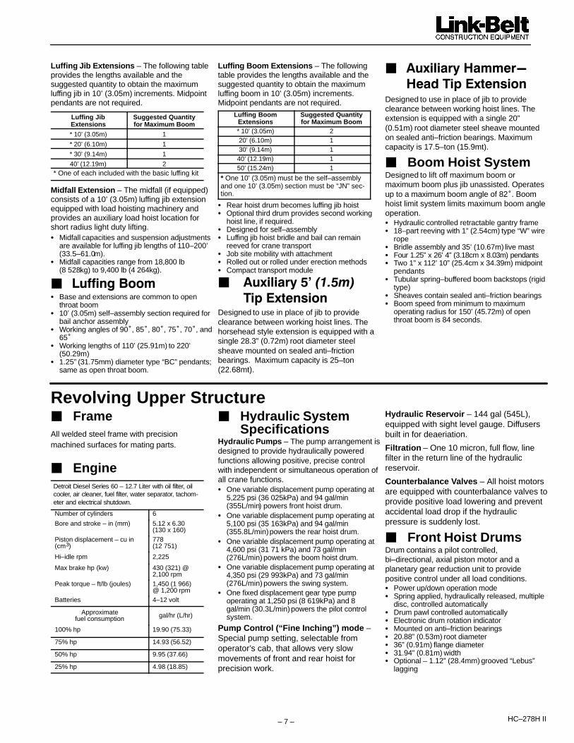
Revolving Upper Structure� FrameAll welded steel frame with precisionmachined surfaces for mating parts.
� EngineDetroit Diesel Series 60 – 12.7 Liter with oil filter, oilcooler, air cleaner, fuel filter, water separator, tachom-eter and electrical shutdown.
Number of cylinders 6Bore and stroke – in (mm) 5.12 x 6.30
(130 x 160)Piston displacement – cu in(cm3)
778(12 751)
Hi–idle rpm 2,225
Max brake hp (kw) 430 (321) @2,100 rpm
Peak torque – ft/lb (joules) 1,450 (1 966)@ 1,200 rpm
Batteries 4–12 volt
Approximatefuel consumption gal/hr (L/hr)
100% hp 19.90 (75.33)
75% hp 14.93 (56.52)
50% hp 9.95 (37.66)
25% hp 4.98 (18.85)
� Hydraulic System Specifications
Hydraulic Pumps – The pump arrangement isdesigned to provide hydraulically poweredfunctions allowing positive, precise controlwith independent or simultaneous operation ofall crane functions.� One variable displacement pump operating at
5,225 psi (36 025kPa) and 94 gal/min(355L/min) powers front hoist drum.
� One variable displacement pump operating at5,100 psi (35 163kPa) and 94 gal/min(355.8L/min) powers the rear hoist drum.
� One variable displacement pump operating at4,600 psi (31 71 kPa) and 73 gal/min(276L/min) powers the boom hoist drum.
� One variable displacement pump operating at4,350 psi (29 993kPa) and 73 gal/min(276L/min) powers the swing system.
� One fixed displacement gear type pumpoperating at 1,250 psi (8 619kPa) and 8gal/min (30.3L/min) powers the pilot controlsystem.
Pump Control (“Fine Inching”) mode –Special pump setting, selectable fromoperator’s cab, that allows very slowmovements of front and rear hoist forprecision work.
Hydraulic Reservoir – 144 gal (545L),equipped with sight level gauge. Diffusersbuilt in for deaeriation.Filtration – One 10 micron, full flow, linefilter in the return line of the hydraulicreservoir.Counterbalance Valves – All hoist motorsare equipped with counterbalance valves toprovide positive load lowering and preventaccidental load drop if the hydraulicpressure is suddenly lost.
� Front Hoist DrumsDrum contains a pilot controlled,bi–directional, axial piston motor and aplanetary gear reduction unit to providepositive control under all load conditions.� Power up/down operation mode� Spring applied, hydraulically released, multiple
disc, controlled automatically� Drum pawl controlled automatically� Electronic drum rotation indicator� Mounted on anti–friction bearings� 20.88” (0.53m) root diameter� 36” (0.91m) flange diameter� 31.94” (0.81m) width� Optional – 1.12” (28.4mm) grooved “Lebus”
lagging

HC–278H II – 8 –
� Rear Hoist DrumsDrum contains a pilot controlled,bi–directional, axial piston motor and aplanetary gear reduction unit to providepositive control under all load conditions.� Power up/down operation mode� Spring applied, hydraulically released, multiple
disc, controlled automatically� Drum pawl controlled automatically� Electronic drum rotation indicator� Mounted on anti–friction bearings� 30.88” (0.78m) root diameter� 40.5” (1.03m) flange diameter� 31.94” (0.81m) width� Optional – 1” (25.4mm) grooved “Lebus”
lagging
� Optional Third HoistDrum
The hydraulic winch is mounted in the boombase section and is used in conjunction with afleeting sheave and three sheave assembly torun the wire rope over the boom top section.� Power up/down operation mode� Automatic brake mode (spring applied,
hydraulically released)� Smooth drum� Mounted on anti–friction bearings� 12.75” (0.32m) root diameter� 22.75” (0.58m) flange diameter� 17” (0.43m) width
� Boom Hoist DrumContains a pilot controlled, bi–directional, axialpiston motor and a planetary gear reductionunit to provide positive control under all loadconditions.� Spring applied, hydraulically released, disc
type brake controlled automatically� 1” (2.54cm) grooved lagging� Drum pawl controlled automatically� Mounted on anti–friction bearings� 20.88” (0.53m) root diameter� 31” (0.79m) flange diameter� 30.75” (0.78m) width
� Swing SystemContains a pilot controlled bi–directional axialpiston motor and the planetary gear reductionunit to provide positive control under all loadconditions.� Spring applied, hydraulically released, 360�
multi–plate brake� Free swing mode when lever is in neutral
position� 360� positive house lock� Audio/visual swing alarm� Maximum swing speed is 2.4 rpm
� Upper CounterweightConsist of a five–piece design. The designallows division of 108,000 lb (48 988kg) ofcounterweight into modules for transportation.This design allows for operating with less thanmaximum counterweight.� Refer to page 3 for counterweight component
weights and dimensions.
� Operator’s Cab and Controls
Fully enclosed modular galvaneal steelcompartment is independently mounted andinsulated to protect against vibration andnoise.� All tinted/tempered safety glass� Sliding entry door� Swing up roof window with wiper� Door and window locks� Heater with circulating fan� Engine instrumentation panel (tachometer, fuel
gauge, voltmeter, engine oil pressure, enginewater temperature, hydraulic oil temperature,hour meter, and service monitor system)
� Electronic drum rotation indicators� Six way adjustable seat with seat belt� Dry chemical fire extinguisher� Hand and foot throttle� Hand and foot operated boom hoist control� Pilot operated single axis control levers� Swing lever with swing brake and horn
located on handle
� Rated CapacityLimiter
Standard Equipment: PAT DS–350G/1334modular system that includes two lineriders,angle sensor, computer, graphics display, andanti–two block equipment to provide thefollowing information:� Graphic representation of crane configuration� Graphical step–by–step crane set–up� Boom length & angle� Jib length & angle� Load on hook� Rated load� Load radius� Tip height� Anti–two block warning & function limiters
operation mode� Provides an audio/visual warning when the
load on hook is within 90% of the rated load.� Provides an audio/visual warning and limits
functions when the load on hook is at 100% ofthe rated load.
� Operator settable alarms include maximumand minimum boom angle and maximum tipheight. These alarms provide an audio/visualwarning only.
Note: Function limiters are activated foranti–two block and overload conditions.These limiters are designed to preventhoist up on front, rear, and third hoistdrums, and boom hoist down.
� Additional Equipment– Standard
� 93” (2.36m) outside diameter turntable bearing� Front and removable left catwalks� 77 (usable) gal (291.5L) fuel tank� Upper lifting links� Two 70–watt headlights
HC–278H II– 9 –
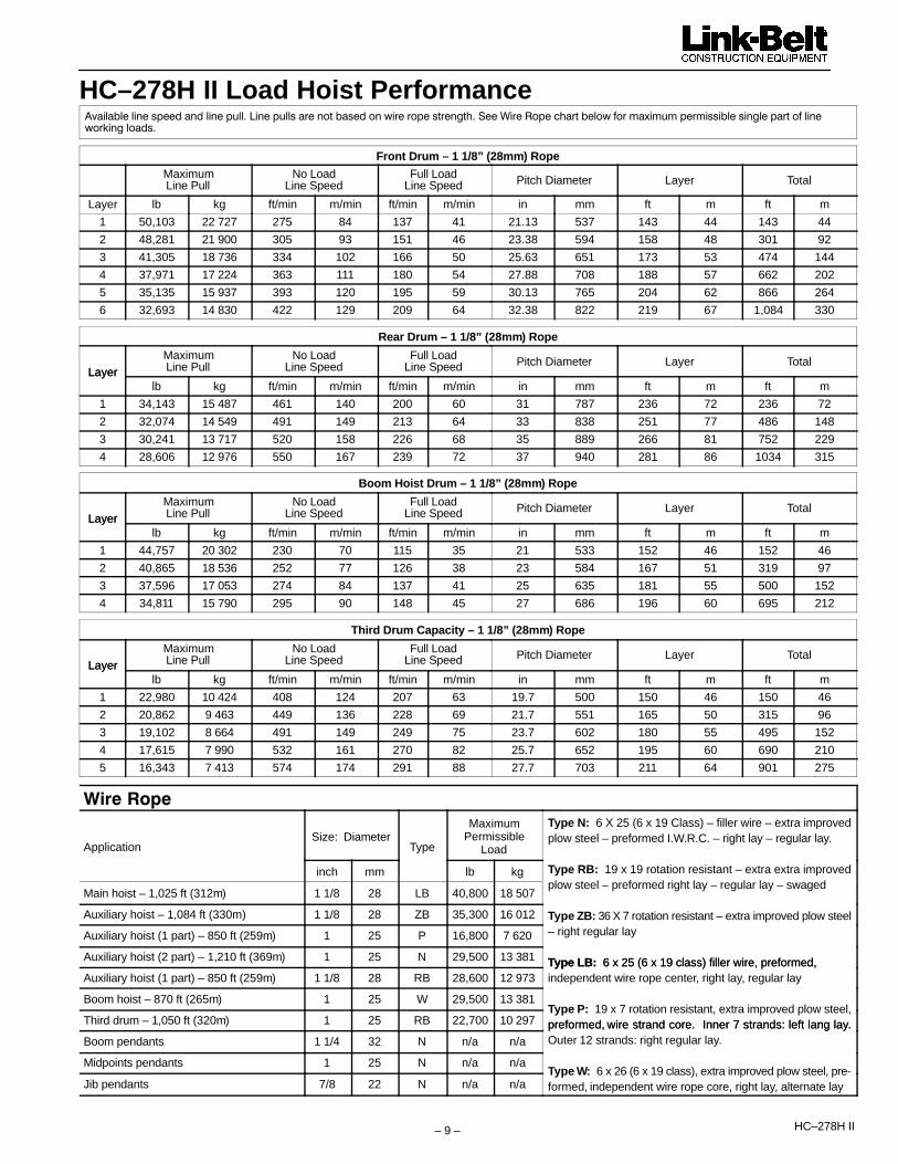
HC–278H II Load Hoist Performance� ������������������������������������������������������������������������������������� ���������!�����������"���#�$�#�#����#���������������������"��������%����������
Front Drum – 1 1/8” (28mm) Rope
MaximumLine Pull
No LoadLine Speed
Full LoadLine Speed Pitch Diameter Layer Total
Layer lb kg ft/min m/min ft/min m/min in mm ft m ft m
1 50,103 22 727 275 84 137 41 21.13 537 143 44 143 44
2 48,281 21 900 305 93 151 46 23.38 594 158 48 301 92
3 41,305 18 736 334 102 166 50 25.63 651 173 53 474 144
4 37,971 17 224 363 111 180 54 27.88 708 188 57 662 202
5 35,135 15 937 393 120 195 59 30.13 765 204 62 866 264
6 32,693 14 830 422 129 209 64 32.38 822 219 67 1,084 330
Rear Drum – 1 1/8” (28mm) Rope
LayerMaximumLine Pull
No LoadLine Speed
Full LoadLine Speed Pitch Diameter Layer Total
Layerlb kg ft/min m/min ft/min m/min in mm ft m ft m
1 34,143 15 487 461 140 200 60 31 787 236 72 236 72
2 32,074 14 549 491 149 213 64 33 838 251 77 486 148
3 30,241 13 717 520 158 226 68 35 889 266 81 752 229
4 28,606 12 976 550 167 239 72 37 940 281 86 1034 315
Boom Hoist Drum – 1 1/8” (28mm) Rope
LayerMaximumLine Pull
No LoadLine Speed
Full LoadLine Speed Pitch Diameter Layer Total
Layerlb kg ft/min m/min ft/min m/min in mm ft m ft m
1 44,757 20 302 230 70 115 35 21 533 152 46 152 46
2 40,865 18 536 252 77 126 38 23 584 167 51 319 97
3 37,596 17 053 274 84 137 41 25 635 181 55 500 152
4 34,811 15 790 295 90 148 45 27 686 196 60 695 212
Third Drum Capacity – 1 1/8” (28mm) Rope
LayerMaximumLine Pull
No LoadLine Speed
Full LoadLine Speed Pitch Diameter Layer Total
Layerlb kg ft/min m/min ft/min m/min in mm ft m ft m
1 22,980 10 424 408 124 207 63 19.7 500 150 46 150 46
2 20,862 9 463 449 136 228 69 21.7 551 165 50 315 96
3 19,102 8 664 491 149 249 75 23.7 602 180 55 495 152
4 17,615 7 990 532 161 270 82 25.7 652 195 60 690 210
5 16,343 7 413 574 174 291 88 27.7 703 211 64 901 275
!��������
ApplicationSize: Diameter
Type
MaximumPermissible
Load
Type N: 6 X 25 (6 x 19 Class) – filler wire – extra improvedplow steel – preformed I.W.R.C. – right lay – regular lay.
inch mm lb kg Type RB: 19 x 19 rotation resistant – extra extra improved
Main hoist – 1,025 ft (312m) 1 1/8 28 LB 40,800 18 507plow steel – preformed right lay – regular lay – swaged
Auxiliary hoist – 1,084 ft (330m) 1 1/8 28 ZB 35,300 16 012 Type ZB: 36 X 7 rotation resistant – extra improved plow steel
Auxiliary hoist (1 part) – 850 ft (259m) 1 25 P 16,800 7 620 – right regular lay
Auxiliary hoist (2 part) – 1,210 ft (369m) 1 25 N 29,500 13 381 Type LB: 6 x 25 (6 x 19 class) filler wire, preformed, Auxiliary hoist (1 part) – 850 ft (259m) 1 1/8 28 RB 28,600 12 973
Type LB: 6 x 25 (6 x 19 class) filler wire, preformed, independent wire rope center, right lay, regular lay
Boom hoist – 870 ft (265m) 1 25 W 29,500 13 381
Third drum – 1,050 ft (320m) 1 25 RB 22,700 10 297Type P: 19 x 7 rotation resistant, extra improved plow steel,preformed, wire strand core. Inner 7 strands: left lang lay.
Boom pendants 1 1/4 32 N n/a n/apreformed, wire strand core. Inner 7 strands: left lang lay.Outer 12 strands: right regular lay.
Midpoints pendants 1 25 N n/a n/a
Jib pendants 7/8 22 N n/a n/aType W: 6 x 26 (6 x 19 class), extra improved plow steel, pre-formed, independent wire rope core, right lay, alternate lay

HC–278H II – 10 –
Carrier� TypeAll welded steel frame with precisionmachined surfaces for mating parts.� 11’ 10” (3.61m) wide� 288” (7.32m) wheel base.� 12 x 6 drive.� 100,000 psi (689.5mPa) alloy steel, triple box
construction.
� AxlesFront� Tubular bogie mounted tridem axles, single
wheels, 115” (2.92m) track� Oil lubed wheel bearings with see through
hubcaps� 43,660 lb (19 804kg) maximum axle loading at
65 mph (105km/hr)Rear� Planetary type, bogie mounted tridem axles,
dual wheels, 110.25” (2.80m)� Oil lubed wheel bearings with see through
hubcaps� 9.14:1 ratio� 85,840 lb (38 937kg) maximum axle loading at
65 mph (105km/hr)
� Suspension� Hendrickson bronze bushed equalizer beams
with rubber bushed torque rods and shockabsorbers on front axle
� WheelsFront – Disc typeRear – Integral with planetary hubs
� TiresStandard – Single –front, dual – rear� 14R25 on/off highway type, tubeless tires
� BrakesService� Full air brakes on all wheel ends. Dual circuit
with modulated emergency brakes.Front� 16.5” x 7” (0.42m x 0.18m) S–Cam brakesRear� 16.5” x 7” (0.42m x 0.18m) S–Cam brakesParking/Emergency� One spring set, air released chamber per rear
axle end. Emergency brakes applyautomatically when air pressure drops below60 psi (413.7kPa) in both systems.
� Steering� Sheppard full integral, hydraulic power� Steering mounted high on sides of frame to
minimize exposure to hazards� High speed, high power system to maximize
maneuverability both on job and on the road
� Transmissions� Standard – Eaton RTO 14908LL with 10
forward speeds and 3 reverse speeds.� Optional – Eaton RTO 14109B ATE CEEMAT.
Nine forward speeds shifted automatically and1 reverse speed.
Auxiliary� Standard – Spicer P–1241–C; used with
manual transmission; midship mounted with4–speed gearing; 2.31:1 first gear ratio.
� Optional – Spicer P–1241–D; used withmanual transmission; midship mounted with4–speed gearing; 1.59:1 first gear ratio.
� ElectricalFour, Group–31 batteries provide 12–voltoperating system and 12–volt starting with1,600 cold cranking amps available. Chargingis provided by a 130 amp alternator.Lights� Two dual, sealed beam headlights� Front, side, and rear directional signals with
4–way hazard system� Stop and tail lights� Rear and side clearance lights� Side turn indicators� Lighted license plate bracket
� OutriggersThe outrigger system is designed with fivehydraulically controlled outriggers that providean optimal 360� working area andsimultaneous operation of steering andoutriggers.� The front and rear outriggers are a double–box
design that allows all four telescoping beamsand jacks to extend/retract independently.
� Hydraulic controls are located at eachoutrigger location with the bumper outriggeroperated at the front bumper. The controls aredesigned to allow both front and rear jacks tobe operated from the driver’s side of carrier ifnecessary.
� Vertical jack cylinders are equipped withholding valves.
� Quick–attach, self–aligning rear outrigger boxwith hydraulic pins
� Quick attach self–aligning front outrigger boxwith manual pins. Hydraulic pins are optional.
� Front left outrigger jack will tilt to allow front boxto roll under carrier frame for removal.
� 34” (0.86m) diameter quick–release steelpontoons
� 24” (0.61m) diameter self–storing aluminumbumper pontoon
Jack Reactions� Maximum 180,000 lb (81 648kg) force and
198 psi (1 365kPa) ground bearing pressureon main outriggers
� Maximum 41,000 lb (18 598kg) force and 91psi (627kPa) ground bearing pressure on frontbumper outrigger
� Carrier EngineSpecifications
Detroit Diesel Series 60 – 12.7 Liter with oil filter,oil cooler, air cleaner, fuel filter, water separator,tachometer, and electrical shutdown.Number of cylinders 6Bore and stroke – in (mm) 5.12” x 6.30”
(130 x 160)Piston displacement – cu. in(cm3)
778(12 751)
Hi–idle rpm 2,225Max brake hp (kw) 430 (321) @
2,100 rpmPeak torque – ft/lb (joules) 1,450 (1 966)
@ 1,200 rpmBatteries 4–12 volt
Approximatefuel consumption gal/hr (L/hr)
100% hp 19.90 (75.33)
75% hp 14.93 (56.52)
50% hp 9.95 (37.66)
25% hp 4.98 (18.85)
� BumperCounterweight
� Standard – “A” counterweight – 11,400 lb(5 171kg)
� Optional – “B” counterweight – 15,300 lb(6 940kg)
� Carrier CabFully enclosed, one person, steel construction,lined with vinyl covered acoustical insulationwith sound reduction insulation and isolatedfrom engine compartmentEquipped with:� Air ride seat with seat belt� 2–speed, electric windshield wiper and
washer� Tilt/telescoping steering column� Front and roof fresh air vents� Safety plate glass on front� Sliding, tinted, rear and right side windows� Roll down door window� Door and window locks� Diagnostic connectors for engine� Fire extinguisher� 19,800 BTU heater/defroster� Rubber floor mat� Horn� Dome light� Accessory plug/lighter

HC–278H II– 11 –
Cab Instrumentation – Tilt–out (for serviceaccess), illuminated, instrument panelincludes:� Speedometer � Odometer� Hourmeter � Tachometer� Voltmeter � Fuel gauge� Light controls � Cruise control� Stop and check engine warning lights� Engine oil pressure gauge� Engine temperature gauge� Front and rear air pressure gauges
with low air pressure warning buzzer/light
� Engine fan override switch� Heater and defroster controls� Park brake switch and indicator light� Engine diagnostic switch
� Additional EquipmentStandard:� Towing shackles, front and rear� Aluminum, full deck fenders and ladders� Outrigger controls located on outrigger boxes� Engine throttle–up control switch
� West Coast–type rear view mirrors withadjustable convex mirror
� 2–way reading bubble levels� Back–up alarm� Mud flaps� Air dryer� Lug wrench� Tire inflation system� Remote plug for block heater� 85 gal (321.76L) fuel tankOptional:
� Spare tires and rims
� Carrier SpeedsAuxiliary–Spicer P–1241–C
Main–Eaton RTO 14908LL4th (0.81) 3rd (1.00) 2nd (1.24) 1st (2.37)
Gear Ratio mph km/h mph km/h mph km/h mph km/h
High
8th7th6th5th
.741.001.361.83
58.443.231.823.6
94.269.551.238.0
47.435.125.819.2
76.356.541.530.9
38.228.320.815.5
61.545.533.524.9
20.014.810.98.1
32.223.817.513.0
Low
4th3rd2nd1stL
2.533.404.636.249.42
17.112.79.36.94.6
27.520.415.011.17.4
13.910.37.65.63.7
22.416.612.29.06.0
11.28.36.14.53.0
18.013.49.87.24.8
5.94.43.22.41.6
9.57.15.13.92.6
Deep Reduction LL 14.56 3.0 4.8 2.4 3.9 1.9 3.1 1.0 1.6
Hi Rev.Lo Rev.
Rev.Rev.
2.899.85
15.04.4
24.17.1
12.13.6
19.55.8
9.82.9
15.84.7
5.11.5
8.22.4
Deep Reduction Rev. 15.22 2.8 4.5 2.3 3.7 1.9 3.1 1.0 1.6
Deep Reduction@ 600 rpm LL 14.56 0.85 1.4 0.7 1.2 .55 0.9 0.3 0.5
Deep Reduction@ 600 rpm Rev. 15.22 0.8 1.3 0.65 1.1 0.5 0.8 0.3 0.5

HC–278H II – 12 –
� Axle LoadsStandard HC–278H II revolving upper equipped Gross Weight Upper Facing Front Upper Facing RearStandard HC–278H II revolving upper equippedwith Detroit Diesel Series 60 diesel engine, rearload hoist drums, 30,000 (13 608kg) “A” coun- * lb kg lb kg lb kg lb kg lb kgload hoist drums, 30,000 (13 608kg) “A” coun-terweight, self undecking equipment mounted on288” (7.32m) wheelbase, 12 x 6 drive carrier,
U 93,330 42 335 –25,121 –11 395 118,451 53 729 44,565 20 214 48,765 22 119288” (7.32m) wheelbase, 12 x 6 drive carrier, 1’ 10” (3.61m) wide, equipped with Detroit Diesel C 70,500 31 979 30,020 13 617 40,480 18 362 30,020 13 617 40,480 18 362Series 60 engine, front center hydraulic jack,Bridgestone tires, and full fuel. T 163,830 74 314 4,899 2 222 158,931 72 090 74,585 33 831 89,245 40 481
Adjust axle weights for adding following Component Weights Front Axle Rear Axle Front Axle Rear AxleAdjust axle weights for adding following components lb kg lb kg lb kg lb kg lb kg
Upperstructure –
Remove self undecking equipment from upper –13,910 –6 310 –695 –315 –13,215 –5 994 –2,200 –998 –11,710 –5 312
Remove counterweight “A” –30,000 –13 608 17,975 8 153 –47,975 –21 761 –24,225 –10 988 –5,775 –2 620
Add rear drum wire rope – 850’ (259m) of 1”(25mm) Type “RB” 1,700 771 –142 –64 1,842 836 497 225 1,203 546
Add front drum wire rope – 1,170’ (357m) of1 1/8” (29mm) Type “LB” 2,738 1 242 165 75 2,572 1 167 405 184 2,333 1 058
Add boom hoist wire rope on drum – 1010’ (308m) of 1” (25mm) Type “W” 1,869 848 –389 –176 2,258 1 024 779 353 1 090 494
Remove boom stops, support struts and leverarms –1,983 899 109 49 –2,092 –948 –522 –237 –1,460 –662
Carrier –
Add front outrigger box 10,560 4 790 6,490 2 944 4,070 1 846 6,490 2 944 4,070 1 846
Add rear outrigger box 10,560 4 790 –4,290 –1 946 14,850 6 736 –4,290 –1 946 14,850 6 736
Add front outrigger jacks 2,200 998 1,350 612 850 386 1,350 612 850 386
Add rear outrigger jacks 2,200 998 –890 –404 3,090 1 402 –890 –404 3,090 1 402
Add main outrigger pontoons 660 299 309 140 351 159 309 140 351 159
Add bumper outrigger pontoon 80 36 31 14 49 22 31 14 49 22
Add “A” bumper counterweight 11,400 5 171 15,570 7 063 –4,170 –1 892 15,570 7 063 –4,170 –1 892
Add “B” bumper counterweight 15,300 6 940 21,591 9 794 –6,291 –2 854 21,591 9 794 –6,291 –2 854
Attachment –
30’ (9.14m) (3rd drum ready) open throat tubularboom base section with 4 connecting pins –hori-zontal over rear of carrier.
4,912 2 228 – – – – –2,736 –1 241 7,648 3 469
Add 3rd drum with rope 4,772 2 165 –6,313 –2 864 1,541 699
35’ (10.67m) boom live mast and bridle – masthorizontal over rear of carrier. 6,922 3 140 6,463 2 932 –459 –208 –6,561 –2 976 13,483 6 116
Boom hoist wire rope (from ball to boom livemast) – mast horizontal over rear of carrier 1,869 248 1,309 593 560 254 –920 –417 2,789 1 265
60’ (18.29m) open throat tubular boom – horizontal over rear of carrier. 10,524 4 774 – – – – –14,229 –6 554 24,753 11 228
45’ (13.72m) hammerhead tubular boom – horizontal over rear of carrier. 10,412 4 729 – – – – –10,577 –4 798 20,989 9 520
*U=Upper C=Carrier T=Total
Axle Maximum Highway Allowable Load
Front Tridem 65,460 lb (29 692kg)
Rear Tridem 128,760 lb (58 405kg)
Link–Belt Construction Equipment Company Lexington, Kentucky www.linkbelt.com�Link–Belt is a registered trademark. Copyright 2005. All rights reserved. We are constantly improving our products and therefore reserve the right to change designs and specifications.

�������������� Hydraulic Lattice Boom Truck Crane
HC–278H II 300–ton (272 metric ton)����������Tube Boom Capacities60 – 330’ (18.29 –100.58 m)
� ����������������� 60’ – 330’ (18.29 – 100.58 m) Open
Throat Boom� 80” (2.03 m) wide x 68” (1.73 m) Deep Boom� ��������������������������� � ������������������ ������������������ � 360� Rotation and Over The Rear Capacities� Counterweight options “ABCDE + AB”,
“ABCDE + A”, ���������� !��������� !������� ������
CAUTION: This material is supplied for reference use only. Operator must refer toin–cab Crane Rating Manual to determine allowable machine lifting capacities andoperating procedures.

HC–278H II –2–
���������������������������������������������� ��������!����"����������
���� !��������� ������������� ���� ������ #������ ��!���� ���������� ��������$��������������������������!�������������������������"���������
��������������$����������"����������������!�����!���������������$
OPERATING INSTRUCTIONSGENERAL:�" #$� ��������� ��� ��$����"%������������ �������&��'�������
�$��(��(�(�'��)�������(�(���"*" +*,!�����) "���������� ������*��������������� �- ��$�
(��(�(� ������'�������� �������(������.���/012"3" 4������������������ � � $�-�����������$�������������$�
����� �����������(����������������(�����&�����)����56�������� ����������&��(������(���7����8"9���������� �����$����������� �������������&��(������$���$���$�� ������������� ��������������������������"
%" ��� ����������&��(�������)��������� �����(����������������(�������"�������������(�������������$� �����(� ��)�������(������-��$��$�������(���������$�������� !�:�� !����.�����(��� � ������-��$��$� �����";���$��(��� ����(� ���!������������(��� ��$����$��$��� ���)����"
," #$��������������$����� ������ �������-��$��$� ������ $���������&������$�( ��'� �-��$��$����� �����)����(�����<������.����� �;� �������7�<.;8� ����� ����� ��������� "
+" ���������� ��� ��������$� �)��5���������(������-��$�.��/0126������00%�7�����.�������� 69��$������#� �8����.��/2+,�6�����)����00��7���������.�)������#� �8"
LIFTING CRANE OPERATION:�" ������ � $�-����������(�����$��1,=�����$�����������
������������ ����2,=�����$����������� �������� �-��$����� ���������'���������(� �������� �����"��������������(� ��)�(������(��$� �������� �����-���$�����$��5�)���5!�$��5�)��! ����!�����!�����-���$������'��� !����"��>$���� ����(��$��5�-$����?�)�� ����$��!�������������� �)��'��� � $�-�����$������������������� �����������������9������(�@��5�>��$/�)�;� �����" ���.���������� �9�������������(������ �-$���� ���������-���������$(���"
2. When using main hook on Open Throat boom while jib isattached, reduce capacities by values shown on CapacityDeductions For Lifting Off Main Boom Hook With Jib Installed.When using main hook on Open Throat boom while tip extensionis attached, reduce capacities by values shown on CapacityDeductions For Lifting Off Main BoomHook With Tip Extension Installed. See Operator’s Manual for alllimitations when raising or lowering attachment.
3. The crane capacities in the shaded areas are based on structuralstrength. The crane capacities in the non–shaded areas arebased on stability ratings.
4. For recommended reeving, parts of line, wire rope type, and wirerope inspection, see Wire Rope Capacity chart, Operator’sManual, and Parts Manual. Rated lifting capacities are based oncorrect reeving. Deduction must be made for excessive reeving.Any reeving over minimum required is considered excessive andmust be accounted for when making lifts. Use Working RangeDiagram to estimate the extra feet of wire rope included inreeving. Then consult Wire Rope Capacity chart to determinethe weight per foot of wire rope type. Deduct this amount foreach extra foot of wire rope before attempting to lift a load.
," >$�������������� �-��$��$����������/�)��������A�����4�� ��� ���������$��)��(������ ��� !�������������� �)���$��'���� $�-�������������������� ���������������� �>��$���������/�)�������A�����4�� �;� ������������(������ ��� "
+" #$��(��(�(�������������������������� ������������������������ ��������$� ������������(����� �*1,!�����)�73�%� �8"
2" ������������� ������� ���&������$��������������������)�( )����������������!������'��?�5 �)������������������������ ������������$�����������������)�����������'������������( �������� �����"
1" #$���� �� �)������������������� ��'����$�� ���"0" ����)��(������$ �����������*%�����$��(������� � �� ���
����� ������&�����"��" ��������������� � ������������(��$��(����)��(����)��(���
����� �������?�)�����$�� (����(�"��" ������� -�����'��� ����������������������������)�( ���������
��������!������'��?�5 �������������������������� �������������$�������!���������� ����������'������������(� ������� �����"
�*" �������������� ������ ������������(��(�(���'��� �������",(""$"�#$��)��(�(� ��)����������� ����$���'����$������-��$ -�������5������������$������(� ��)���� ����������( -������"
13. Load ratings in this Crane Rating Manual are based on freelysuspended loads and make no allowances for such factors as theeffect of ground conditions and operating speeds. The operatorshall therefore reduce load ratings in order to take theseconditions into account.
14. Rated lifting capacities do not account for the effects of wind on asuspended load or boom. Lifting capacities should beconsidered acceptable for wind speeds up to 20 m.p.h. andappropriately reduced for wind speeds greater than 20 m.p.h.Extreme caution should be used when lifting heavy loads orloads with large wind sail area under high wind conditions (over20 m.p.h.). See Wind Restriction charts in this manual forappropriate capacity reductions.
15. The 35’ live mast must be used for all capacities.16. These capacities apply only to the crane as originally
manufactured and normally equipped by Link–Belt ConstructionEquipment Company.
17. Do not operate at radii and boom lengths where the Crane RatingManual lists no capacity. Do not use longer booms or jibs thanthose listed in this Crane Rating Manual. Any of the above cancause a tipping condition, or boom and jib failure.
18. Open throat booms should be erected and lowered over the endfor maximum stability. Consult the proper liftoff chart in thismanual before erecting or lowering open throat booms.
19. For boom lengths up to and including 220’, “J”, “JE”, or “JN”(.375” Wall) boom extensions must be used. 220’ of boomincludes a 30’ base section, 160’ of extensions, and a 30’ topsection. Extensions added beyond the first 160’ of extensionsmust be “H” or “HJ” (.259” Wall) boom extensions.
DEFINITIONS:1. Load Radius: Horizontal distance from a projection of the axis of
rotation to the supporting surface, before loading, to the center ofthe vertical hoist line or tackle with load applied.
2. Boom Angle: The angle between the boom base section andhorizontal with freely suspended load at the rated radius.
3. Working Area: Area measured in a circular arc about thecenterline of rotation as shown on the Working Area Diagram.
4. Freely Suspended Load: Load hanging free with no directexternal force applied except by the hoist line.
5. Side Load: Horizontal side force applied to the lifted load eitheron the ground or in the air.

–3– HC–278H II
WIRE ROPE CAPACITY
1”Parts of
Line TypeDB
TypeCC
TypeLB
TypeRB
1 29,500 30,700 32,500 22,700*
2 59,000 61,400 65,000 45,400
3 88,500 92,100 97,500 68,100
4 118,000 122,800 130,000 90,800
5 147,500 153,500 162,500 113,500
6 177,000 184,200 195,000 136,200
7 206,500 214,900 227,500 158,900
8 236,000 245,600 260,000 181,600
9 265,500 276,300 292,500 204,300
10 295,000 307,000 325,000 227,000
11 324,500 337,700 357,500 249,700
12 354,000 368,400 390,000 272,400
Weight(lb/ft) 1.85 2.03 1.85 2.00
1–1/8” (28 mm)Parts of
Line TypeDB
TypeZB
TypeLB
TypeRB
TypeSB
1 37,100 35,300 40,800 28,600 52,400
2 74,200 70,600 81,600 57,200 104,800
3 111,300 105,900 122,400 85,800 157,200
4 148,400 141,200 163,200 114,400 209,600
5 185,500 176,500 204,000 143,000 262,000
6 222,600 211,800 244,800 171,600 314,400
7 259,700 247,100 285,600 200,200 366,800
8 296,800 382,400 326,400 228,800 419,200
9 333,900 317,700 367,200 257,400 471,600
10 371,000 353,000 408,000 286,000 524,000
11 408,100 388,300 448,800 314,600 576,400
12 445,200 423,600 489,600 343,200 628,800
Weight(lb/ft) 2.34 2.58 2.34 2.50 2.57
LBCEType Description
DB 6 x 26 (6 x 19 Class), Warrington Seale, Extra Improved PlowSteel, Preformed, Right Lay – Regular Lay, I.W.R.C.
ZB 36 x 7 Non–Rotating, Extra Improved Plow Steel, Right Lay –Regular Lay, Compacted
LB 6 Strand, Compacted Strand, Seale or Warrington Seale,I.W.R.C., Preformed, Right Lay – Regular Lay
RB 19 x 19 Rotation Resistant, High Strength, Preformed – RightLay – Regular Lay. Swaged
CC 36 x 7 Classification Non–Rotating – Extra Extra ImprovedPlow Steel, Right Lay – Regular Lay, Compact Strand
SB 8 Strand, Preformed – Right Lay Regular Lay
Notes: 1. Capacities shown are in pounds and working loads must not exceedthe ratings on the capacity chart in the Crane Rating Manual.2. Study Operator’s Manual for wire rope inspection procedures.
WORKING AREAS
BoomCL
FrontPontoonSupport
CL
Center OfRotation
Rear PontoonSupport
CL
Carrier On Outriggers
Longitudinal COf Carrier
L
CL Front Axle(Bogie)
Rear Axle(Bogie)
Center OfRotation
Boom StraightOver Rear
CL
Boom
CL
Carrier On Tires
CL
360�
OverRear
SeeNote
See Note
SeeNote
Note:1. These Lines Determine The Limiting Position Of Any
Load For Operation Within Working Areas Indicated.
ALLOWABLE COUNTERWEIGHTS
Counterweight Combina- Allowable open throat boom lengthsCounterweight Combina-tions (1) Upper + Bumper w/o Jib (ft) With Jib (ft) (3)
0 + 0 on outriggers 60–190
A + 0 on outriggers (2) 60–220 PROHIBITED
ABC + 0 on outriggers (2) 60–270
ABCDE + 0 on outriggers (2) 60–300 60–260
ABCDE + A on outriggers (2) 60–320 PROHIBITED
ABCDE + AB on outriggers (2) 60–330 60–300
Notes:1. Counterweight combinations are for a crane equipped with a 250 ton open
throat boom. Counterweight combinations must be used only as shown on this chart, otherwise crane may overturn or other damage may occur.
2. “A” Upper Counterweight – 30,000 lbs. “ABC” Upper Counterweight – 76,700 lbs.“ABCDE” Upper Counterweight – 108,000 lbs. “A” Bumper Counterweight – 11,400 lbs.“AB” Bumper Counterweight – 26,700 lbs.
3. Do not swing over the side until outrigger beams are fully extended and outrigger jacks set with upper counterweights, or crane may overturn.
4. Maximum jib length is 100 ft.
HC–278H II –4–
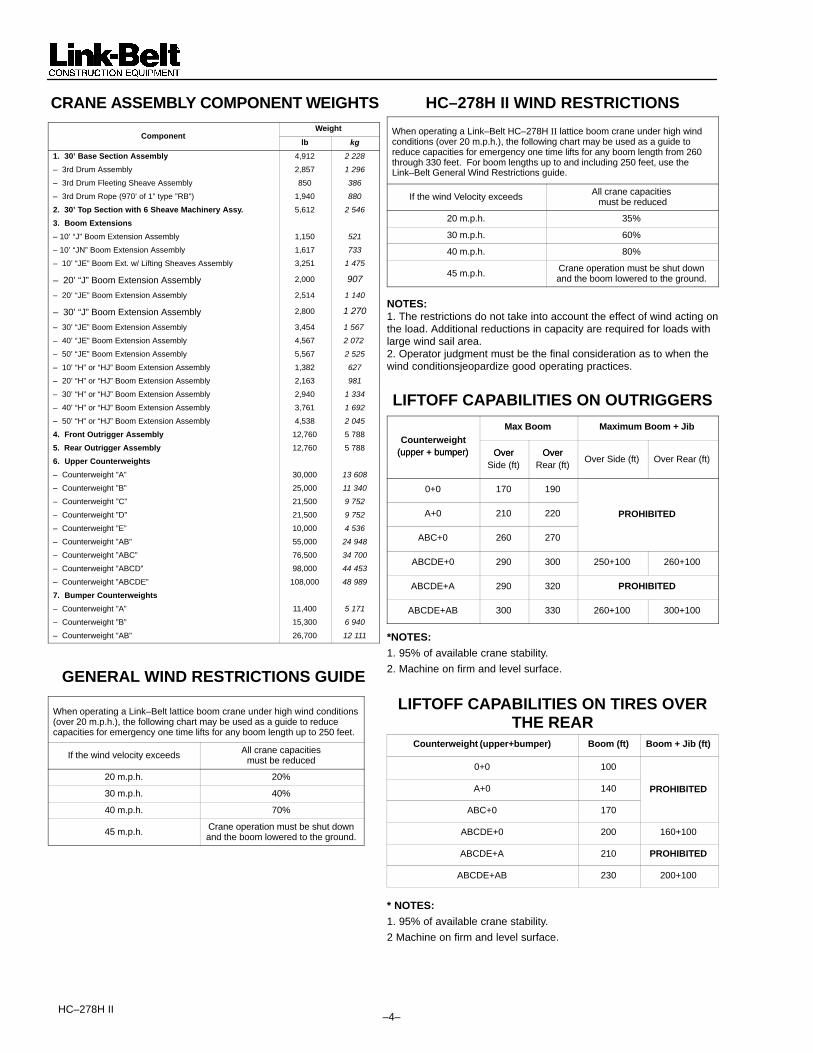
CRANE ASSEMBLY COMPONENT WEIGHTSWeight
Componentlb kg
1. 30’ Base Section Assembly 4,912 2 228
– 3rd Drum Assembly 2,857 1 296
– 3rd Drum Fleeting Sheave Assembly 850 386
– 3rd Drum Rope (970’ of 1” type ”RB”) 1,940 880
2. 30’ Top Section with 6 Sheave Machinery Assy. 5,612 2 546
3. Boom Extensions
– 10’ “J” Boom Extension Assembly 1,150 521
– 10’ “JN” Boom Extension Assembly 1,617 733
– 10’ “JE” Boom Ext. w/ Lifting Sheaves Assembly 3,251 1 475
– 20’ “J” Boom Extension Assembly 2,000 907
– 20’ “JE” Boom Extension Assembly 2,514 1 140
– 30’ “J” Boom Extension Assembly 2,800 1 270
– 30’ “JE” Boom Extension Assembly 3,454 1 567
– 40’ “JE” Boom Extension Assembly 4,567 2 072
– 50’ “JE” Boom Extension Assembly 5,567 2 525
– 10’ “H” or “HJ” Boom Extension Assembly 1,382 627
– 20’ “H” or “HJ” Boom Extension Assembly 2,163 981
– 30’ “H” or “HJ” Boom Extension Assembly 2,940 1 334
– 40’ “H” or “HJ” Boom Extension Assembly 3,761 1 692
– 50’ “H” or “HJ” Boom Extension Assembly 4,538 2 045
4. Front Outrigger Assembly 12,760 5 788
5. Rear Outrigger Assembly 12,760 5 788
6. Upper Counterweights
– Counterweight ”A” 30,000 13 608
– Counterweight ”B” 25,000 11 340
– Counterweight ”C” 21,500 9 752
– Counterweight ”D” 21,500 9 752
– Counterweight ”E” 10,000 4 536
– Counterweight ”AB” 55,000 24 948
– Counterweight ”ABC” 76,500 34 700
– Counterweight ”ABCD” 98,000 44 453
– Counterweight ”ABCDE” 108,000 48 989
7. Bumper Counterweights
– Counterweight ”A” 11,400 5 171
– Counterweight ”B” 15,300 6 940
– Counterweight ”AB” 26,700 12 111
GENERAL WIND RESTRICTIONS GUIDE
When operating a Link–Belt lattice boom crane under high wind conditions(over 20 m.p.h.), the following chart may be used as a guide to reduce capacities for emergency one time lifts for any boom length up to 250 feet.
If the wind velocity exceeds All crane capacitiesmust be reduced
20 m.p.h. 20%
30 m.p.h. 40%
40 m.p.h. 70%
45 m.p.h. Crane operation must be shut downand the boom lowered to the ground.
HC–278H II WIND RESTRICTIONS
When operating a Link–Belt HC–278H II lattice boom crane under high windconditions (over 20 m.p.h.), the following chart may be used as a guide toreduce capacities for emergency one time lifts for any boom length from 260through 330 feet. For boom lengths up to and including 250 feet, use theLink–Belt General Wind Restrictions guide.
If the wind Velocity exceeds All crane capacities must be reduced
20 m.p.h. 35%
30 m.p.h. 60%
40 m.p.h. 80%
45 m.p.h. Crane operation must be shut downand the boom lowered to the ground.
NOTES:1. The restrictions do not take into account the effect of wind acting onthe load. Additional reductions in capacity are required for loads withlarge wind sail area.2. Operator judgment must be the final consideration as to when thewind conditionsjeopardize good operating practices.
LIFTOFF CAPABILITIES ON OUTRIGGERS
Max Boom Maximum Boom + JibCounterweight
(upper + bumper) Over Over(upper + bumper) OverSide (ft)
OverRear (ft)
Over Side (ft) Over Rear (ft)
0+0 170 190
A+0 210 220 PROHIBITED
ABC+0 260 270
ABCDE+0 290 300 250+100 260+100
ABCDE+A 290 320 PROHIBITED
ABCDE+AB 300 330 260+100 300+100
*NOTES:
1. 95% of available crane stability.
2. Machine on firm and level surface.
LIFTOFF CAPABILITIES ON TIRES OVERTHE REAR
Counterweight (upper+bumper) Boom (ft) Boom + Jib (ft)
0+0 100
A+0 140 PROHIBITED
ABC+0 170
ABCDE+0 200 160+100
ABCDE+A 210 PROHIBITED
ABCDE+AB 230 200+100
* NOTES:
1. 95% of available crane stability.
2 Machine on firm and level surface.

–5– HC–278H II
LIVE MAST LIFTING CAPACITIESCAPACITY (No Counterweight)
Mast RadiusOn Tires On Outriggers
12’ – 17’ 55,000 lbs. 76,500 lbs.
17’ – 28’ 30,000 lbs. 76,500 lbs.
�������1. Refer to Operator’s Manual.2. Live mast backstops must be in position and operative.3. Use rear drum only. Reeve hoist line to drum over mast cross
member. Reeve hoist rope with three (3) parts of 1.00”, 1–1/8”(28.5 mm) diameter wire rope.
4. 76,500 lbs. capacity is based on strength of material.5. Refer to “Crane Assembly Component Weights” for weight of
components when lifting from live mast.
10’ EXT. LIFTING CAPACITIES – 360����%
��% ��&'�(����
�)*+��&%�*(On Tires
Without Ctwt (lb)On Outriggers
With/Without Ctwt (lb)
10.31 82.0 55,000 76,500
11 80.9 55,000 76,500
12 79.3 55,000 76,500
13 77.6 55,000 76,500
14 75.9 55,000 76,500
15 74.3 55,000 76,500
16 72.6 52,400 76,500
17 70.9 49,600 76,500
18 69.1 47,000 76,500
19 67.4 44,700 76,500
20 65.6 42,500 76,500
21 63.8 40,500 76,500
22 61.9 38,600 76,500
23 60.1 36,200 76,500
24 58.1 34,000 76,500
25 56.2 32,000 76,500
26 54.1 30,100 76,500
27 52.1 28,500 76,500
28 49.9 27,000 76,500
29 47.7 25,600 76,500
30 45.4 24,300 76,500
31 42.9 23,100 76,500
32 40.3 21,900 76,500
33 37.6 20,900 76,500
34 34.7 19,900 75,000
35 31.5 19,000 70,800
36 27.9 18,100 66,900
�������1. Refer to operator’s manual.2. Use front drum only. Reeve hoist line under mast cross
member.3. Reeve hoist rope with three (3) parts of 1.125” or 1.00”
diameter wire rope. See operator’s manual for correctprocedure.
4. Do not swing upper when crane is on tires and upper equippedwith “A”, “AB”, “ABC”, “ABCD”, OR “ABCDE” counterweights.
5. Refer to “Crane assembly component weights” for weights ofcomponents when lifting with the 10’ extension.
6. 10’ extension capacities are resricted to crane assmebly/disassembly. Do not lift loads with 10’ extension for anyreason other than crane assembly/disassembly.

HC–278H II –6–
WORKING RANGE DIAGRAM
Notes:1. Boom geometry shown is for unloaded condition and crane standing level on firm supporting surface. Boom
deflection, subsequent radius and boom angle change must be accounted for when applying load to hook.2. Maximum and minimum boom angles are equal to the values listed in the capacity chart for each boom length.
Hei
gh
t O
f M
ain
Bo
om
Hea
d A
bo
ve G
rou
nd
,- ����..- �"�������"��������������
Mai
n B
oo
m L
eng
th
�����)*���% ��!�����)��+)���'�������)
Maximum Boom AngleSee Note 2.
Minimum Boom AngleSee Note 2.
330’
320’
310’
300’290’
280’270’
260’
250’240’230’
220’210’
200’
190’
180’170’160’
150’
140’
130’
120’
110’100’
90’
80’70’
60’
320’
300’
280’
260’
240’
220’
200’
180’
160’
140’
120’
100’
80’
60’
40’
20’
0’
340’
82�
70�
60�
50�
40�
30�
20�
320’ 300’ 280’ 260’ 240’ 220’ 200’ 180’ 160’ 140’ 120’ 100’ 80’ 60’ 40’ 20’
CL OF ROTATION
82B
–7– HC–278H II
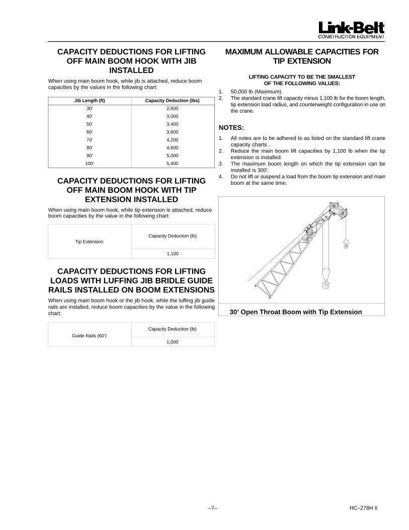
CAPACITY DEDUCTIONS FOR LIFTINGOFF MAIN BOOM HOOK WITH JIB
INSTALLEDWhen using main boom hook, while jib is attached, reduce boom capacities by the values in the following chart:
Jib Length (ft) Capacity Deduction (lbs)
30’ 2,600
40’ 3,000
50’ 3,400
60’ 3,800
70’ 4,200
80’ 4,600
90’ 5,000
100’ 5,400
CAPACITY DEDUCTIONS FOR LIFTINGOFF MAIN BOOM HOOK WITH TIP
EXTENSION INSTALLEDWhen using main boom hook, while tip extension is attached, reduceboom capacities by the value in the following chart:
Tip ExtensionCapacity Deduction (lb)
1,100
CAPACITY DEDUCTIONS FOR LIFTINGLOADS WITH LUFFING JIB BRIDLE GUIDERAILS INSTALLED ON BOOM EXTENSIONSWhen using main boom hook or the jib hook, while the luffing jib guiderails are installed, reduce boom capacities by the value in the followingchart:
Capacity Deduction (lb)Guide Rails (60’)
1,000
MAXIMUM ALLOWABLE CAPACITIES FORTIP EXTENSION
LIFTING CAPACITY TO BE THE SMALLESTOF THE FOLLOWING VALUES:
1. 50,000 lb (Maximum).2. The standard crane lift capacity minus 1,100 lb for the boom length,
tip extension load radius, and counterweight configuration in use onthe crane.
NOTES:
1. All notes are to be adhered to as listed on the standard lift cranecapacity charts .
2. Reduce the main boom lift capacities by 1,100 lb when the tipextension is installed.
3. The maximum boom length on which the tip extension can beinstalled is 300’.
4. Do not lift or suspend a load from the boom tip extension and mainboom at the same time.
30’ Open Throat Boom with Tip Extension

HC–278H II –8–
A BA
CE D
B
Main Boom Capacities – On Outriggers – 60 Ft Open Throat Tube BoomLoad Boom Counterweight Combinations – Upper + BumperLoad
RadiusBoomAngle Over The Rear 360 Degree RotationRadius
(ft)Angle(deg) ABCDE+0 ABCDE+A ABCDE+AB 0+0 A+0 ABC+0 ABCDE+0 ABCDE+A ABCDE+AB
10.4 * ––– 600,000 * 600,000 * 600,000 * ––– ––– ––– ––– ––– –––12 81.5 500,000 500,000 500,000 380,700 398,100 417,500 429,200 412,800 390,40013 80.6 438,200 441,800 441,800 351,700 379,600 398,300 409,400 393,900 372,40014 79.6 418,800 422,400 422,400 326,600 362,200 380,700 391,400 376,400 356,00015 78.6 401,200 404,800 404,800 304,800 338,000 364,600 374,800 360,600 340,90016 77.6 384,800 388,400 388,400 285,600 316,900 349,700 359,600 345,800 326,90017 76.7 368,200 368,200 368,200 268,700 298,100 335,800 345,400 332,200 314,10018 75.7 347,700 347,700 347,700 253,500 281,400 323,400 332,400 319,800 302,30019 74.7 329,400 329,400 329,400 240,100 266,400 308,500 320,900 308,500 291,60020 73.7 312,900 312,900 312,900 227,800 252,800 292,900 310,200 298,200 282,00025 68.7 250,300 250,300 250,300 152,400 201,300 233,500 250,300 250,300 243,00030 63.4 208,600 208,600 208,600 107,200 149,600 193,500 208,600 208,600 207,50035 58.0 178,800 178,800 178,800 81,800 115,000 164,700 178,800 178,800 178,80040 52.1 156,200 156,200 156,200 65,700 92,800 135,700 156,200 156,200 156,20050 38.7 122,800 122,800 122,800 46,100 66,100 97,600 118,200 121,400 122,80060 18.7 90,300 90,300 90,300 34,600 50,400 75,400 90,300 90,300 90,300
* – See note 1 under General Notes on page 2.
Main Boom Capacities – On Outriggers – 70 Ft Open Throat Tube BoomLoad Boom Counterweight Combinations – Upper + BumperLoad
RadiusBoomAngle Over The Rear 360 Degree RotationRadius
(ft)Angle(deg) ABCDE+0 ABCDE+A ABCDE+AB 0+0 A+0 ABC+0 ABCDE+0 ABCDE+A ABCDE+AB
12.91 82.0 438,700 442,300 442,300 353,400 380,100 398,800 409,800 394,200 372,70013 81.9 436,900 440,500 440,500 351,000 378,500 397,100 408,100 392,600 371,10014 81.1 417,600 421,200 421,200 325,900 361,400 379,600 390,300 375,300 354,90015 80.3 400,100 403,700 403,700 304,300 337,300 363,600 373,700 359,500 339,80016 79.4 383,800 387,400 387,400 285,100 316,300 348,700 358,600 344,800 325,90017 78.6 368,200 368,200 368,200 268,300 297,500 335,000 344,500 331,300 313,30018 77.8 347,700 347,700 347,700 253,100 281,000 322,600 331,600 319,000 301,50019 76.9 329,400 329,400 329,400 239,700 266,000 308,000 320,100 307,700 290,80020 76.1 312,900 312,900 312,900 227,500 252,400 292,400 309,400 297,500 281,20025 71.8 250,300 250,300 250,300 153,200 201,000 233,100 250,300 250,300 242,40030 67.5 208,600 208,600 208,600 107,800 150,200 193,200 208,600 208,600 207,20035 63.0 178,800 178,800 178,800 82,200 115,400 164,500 178,800 178,800 178,80040 58.3 154,700 154,700 154,700 66,000 93,100 136,000 154,700 154,700 154,70050 48.0 118,600 118,600 118,600 46,300 66,300 97,800 118,400 118,600 118,60060 35.7 93,800 93,800 93,800 34,900 50,600 75,600 91,800 93,800 93,80070 17.3 75,500 75,500 75,500 27,300 40,400 61,000 74,500 75,500 75,500
Main Boom Capacities – On Outriggers – 80 Ft Open Throat Tube BoomLoad Boom Counterweight Combinations – Upper + BumperLoad
RadiusBoomAngle Over The Rear 360 Degree RotationRadius
(ft)Angle(deg) ABCDE+0 ABCDE+A ABCDE+AB 0+0 A+0 ABC+0 ABCDE+0 ABCDE+A ABCDE+AB
14.3 82.0 410,800 414,400 414,400 318,400 352,800 373,300 383,800 369,000 349,00015 81.5 398,800 402,400 402,400 303,500 336,400 362,400 372,400 358,300 338,60016 80.8 382,600 386,200 386,200 284,400 315,500 347,600 357,500 343,700 325,00017 80.0 367,600 368,200 368,200 267,600 296,800 333,900 343,400 330,200 312,20018 79.3 347,700 347,700 347,700 252,500 280,300 321,600 330,500 318,000 300,50019 78.6 329,400 329,400 329,400 239,200 265,400 307,300 319,100 306,800 289,90020 77.9 312,900 312,900 312,900 227,000 251,900 291,700 308,500 296,600 280,40025 74.2 250,300 250,300 250,300 153,700 200,600 232,600 250,300 250,300 241,70030 70.4 207,900 207,900 207,900 108,100 150,500 192,800 207,900 207,900 206,80035 66.6 173,700 173,700 173,700 82,400 115,600 164,100 173,700 173,700 173,70040 62.6 148,900 148,900 148,900 66,200 93,200 136,000 148,900 148,900 148,90050 54.2 114,600 114,600 114,600 46,300 66,400 97,800 114,600 114,600 114,60060 44.7 91,200 91,200 91,200 35,000 50,600 75,600 91,200 91,200 91,20070 33.3 75,100 75,100 75,100 27,400 40,400 61,000 74,500 75,100 75,10080 16.2 61,300 61,300 61,300 22,000 33,100 50,700 61,300 61,300 61,300

–9– HC–278H II
A BA
CE D
B
Main Boom Capacities – On Outriggers – 90 Ft Open Throat Tube BoomLoad Boom Counterweight Combinations – Upper + BumperLoad
RadiusBoomAngle Over The Rear 360 Degree RotationRadius
(ft)Angle(deg) ABCDE+0 ABCDE+A ABCDE+AB 0+0 A+0 ABC+0 ABCDE+0 ABCDE+A ABCDE+AB
15.69 82.0 387,100 390,700 390,700 290,700 322,300 351,800 361,700 347,700 328,60016 81.8 382,200 385,900 385,900 285,000 316,100 347,400 357,200 343,400 324,70017 81.2 367,300 368,200 368,200 268,300 297,400 333,700 343,200 329,900 312,00018 80.5 347,700 347,700 347,700 253,200 280,900 321,400 330,300 317,800 300,30019 79.9 329,400 329,400 329,400 239,800 265,900 307,700 318,900 306,600 289,70020 79.2 312,900 312,900 312,900 227,600 252,400 292,200 308,300 296,400 280,20025 76.0 250,300 250,300 250,300 155,900 201,000 233,000 250,300 250,300 241,60030 72.7 208,600 208,600 208,600 109,600 151,900 193,200 208,600 208,600 207,10035 69.3 178,800 178,800 178,800 83,500 116,700 164,400 178,800 178,800 178,80040 65.8 155,800 155,800 155,800 67,000 94,000 136,900 155,800 155,800 155,80050 58.6 122,800 122,800 122,800 46,900 66,900 98,300 119,000 121,900 122,80060 50.8 100,200 100,800 100,800 35,400 51,000 76,000 92,200 94,600 98,00070 42.0 81,200 85,000 85,000 27,700 40,600 61,300 74,800 76,800 79,60080 31.4 68,000 73,200 73,200 22,200 33,400 50,800 62,400 64,100 66,50090 15.2 58,000 63,300 63,800 18,100 27,800 43,100 53,100 54,600 56,700
Main Boom Capacities – On Outriggers – 100 Ft Open Throat Tube BoomLoad Boom Counterweight Combinations – Upper + BumperLoad
RadiusBoomAngle Over The Rear 360 Degree RotationRadius
(ft)Angle(deg) ABCDE+0 ABCDE+A ABCDE+AB 0+0 A+0 ABC+0 ABCDE+0 ABCDE+A ABCDE+AB
17.08 82.0 365,000 366,400 366,400 266,100 295,000 331,400 340,800 327,600 309,70018 81.5 347,700 347,700 347,700 252,400 280,100 320,300 329,100 316,600 299,10019 80.9 329,400 329,400 329,400 239,100 265,100 306,800 317,800 305,500 288,60020 80.3 312,900 312,900 312,900 226,900 251,600 291,300 307,300 295,300 279,20025 77.4 250,300 250,300 250,300 156,200 200,500 232,400 250,300 250,300 240,80030 74.4 208,600 208,600 208,600 109,700 152,000 192,600 208,600 208,600 206,50035 71.4 178,600 178,600 178,600 83,500 116,700 163,800 178,600 178,600 178,60040 68.4 155,300 155,300 155,300 67,000 94,000 136,800 155,300 155,300 155,30050 62.1 122,300 122,300 122,300 46,800 66,800 98,200 118,900 121,800 122,30060 55.4 100,000 100,400 100,400 35,300 50,900 75,900 92,000 94,500 97,80070 48.1 81,200 84,600 84,600 27,500 40,400 61,100 74,600 76,700 79,40080 39.8 67,900 72,800 72,800 22,100 33,200 50,700 62,200 63,900 66,30090 29.7 57,900 63,200 63,500 18,000 27,700 42,900 53,000 54,500 56,500
100 14.5 50,200 54,900 56,000 14,800 23,400 37,000 45,800 47,200 49,000
Main Boom Capacities – On Outriggers – 110 Ft Open Throat Tube BoomLoad Boom Counterweight Combinations – Upper + BumperLoad
RadiusBoomAngle Over The Rear 360 Degree RotationRadius
(ft)Angle(deg) ABCDE+0 ABCDE+A ABCDE+AB 0+0 A+0 ABC+0 ABCDE+0 ABCDE+A ABCDE+AB
18.48 82.0 338,700 338,700 338,700 244,900 271,800 313,700 322,500 310,000 292,80019 81.7 329,400 329,400 329,400 238,300 264,200 305,800 316,700 304,300 287,40020 81.2 312,900 312,900 312,900 226,100 250,800 290,300 306,200 294,200 278,10025 78.6 250,300 250,300 250,300 156,400 199,800 231,600 250,300 250,300 239,90030 75.9 208,600 208,600 208,600 109,800 152,100 192,000 208,600 208,600 205,80035 73.2 178,000 178,000 178,000 83,500 116,700 163,200 178,000 178,000 178,00040 70.4 154,800 154,800 154,800 66,900 93,900 136,600 154,800 154,800 154,80050 64.8 121,800 121,800 121,800 46,600 66,600 98,000 118,700 121,600 121,80060 58.9 99,800 99,900 99,900 35,100 50,700 75,700 91,800 94,200 97,60070 52.6 81,000 84,100 84,100 27,300 40,400 60,900 74,400 76,400 79,20080 45.7 67,600 72,400 72,400 21,900 33,000 50,500 62,000 63,700 66,10090 37.9 57,700 63,000 63,100 17,800 27,500 42,700 52,700 54,300 56,300
100 28.3 50,000 54,700 55,700 14,600 23,200 36,900 45,600 47,000 48,800110 13.8 43,800 48,000 49,400 12,100 19,800 32,000 40,000 41,100 42,700
HC–278H II –10–
A BA
CE D
B
Main Boom Capacities – On Outriggers – 120 Ft Open Throat Tube BoomLoad Boom Counterweight Combinations – Upper + BumperLoad
RadiusBoomAngle Over The Rear 360 Degree RotationRadius
(ft)Angle(deg) ABCDE+0 ABCDE+A ABCDE+AB 0+0 A+0 ABC+0 ABCDE+0 ABCDE+A ABCDE+AB
19.87 82.0 314,500 314,500 314,500 226,800 251,600 291,300 306,300 294,300 278,200
20 81.9 312,900 312,900 312,900 225,300 249,900 289,300 305,000 293,100 277,000
25 79.5 250,300 250,300 250,300 156,600 199,100 230,900 250,300 250,300 239,000
30 77.1 208,100 208,100 208,100 109,800 152,000 191,300 208,100 208,100 205,100
35 74.6 177,400 177,400 177,400 83,400 116,600 162,600 177,400 177,400 177,400
40 72.1 154,200 154,200 154,200 66,800 93,700 136,500 154,200 154,200 154,200
50 67.0 121,500 121,500 121,500 46,400 66,400 97,800 118,500 121,500 121,500
60 61.7 99,400 99,400 99,400 34,900 50,400 75,400 91,500 94,000 97,300
70 56.2 80,800 83,600 83,600 27,100 40,200 60,600 74,100 76,200 78,900
80 50.2 67,300 72,000 72,000 21,600 32,800 50,200 61,700 63,400 65,800
90 43.6 57,400 62,700 62,700 17,600 27,300 42,400 52,400 54,000 56,000
100 36.2 49,700 54,400 55,200 14,400 23,000 36,600 45,300 46,700 48,500
110 27.1 43,600 47,800 49,200 11,900 19,600 31,800 39,800 40,900 42,500
120 13.2 38,600 42,400 43,200 9,800 16,800 27,800 35,100 36,200 37,700
Main Boom Capacities – On Outriggers – 130 Ft Open Throat Tube BoomLoad Boom Counterweight Combinations – Upper + BumperLoad
RadiusBoomAngle Over The Rear 360 Degree RotationRadius
(ft)Angle(deg) ABCDE+0 ABCDE+A ABCDE+AB 0+0 A+0 ABC+0 ABCDE+0 ABCDE+A ABCDE+AB
21.26 82.0 292,100 292,100 292,100 210,800 234,200 271,200 291,800 280,700 264,900
25 80.3 250,100 250,100 250,100 156,700 198,400 230,000 250,100 250,100 238,000
30 78.1 207,400 207,400 207,400 109,800 152,000 190,600 207,400 207,400 204,400
35 75.8 176,700 176,700 176,700 83,300 116,500 162,000 176,700 176,700 176,700
40 73.5 153,600 153,600 153,600 66,600 93,500 136,300 153,600 153,600 153,600
50 68.9 121,000 121,000 121,000 46,200 66,200 97,500 118,200 121,000 121,000
60 64.1 98,900 98,900 98,900 34,600 50,200 75,200 91,200 93,700 97,000
70 59.1 80,500 83,100 83,100 26,800 39,900 60,300 73,800 75,900 78,600
80 53.8 67,000 71,500 71,500 21,400 32,500 49,900 61,400 63,100 65,500
90 48.1 57,100 62,200 62,200 17,300 27,000 42,100 52,100 53,700 55,700
100 41.9 49,400 54,100 54,800 14,100 22,700 36,300 45,000 46,300 48,200
110 34.7 43,200 47,500 48,600 11,600 19,300 31,500 39,500 40,500 42,200
120 26.0 38,400 42,100 43,000 9,500 16,500 27,600 34,800 35,900 37,400
130 12.7 34,200 37,700 38,300 7,800 14,200 24,300 30,900 31,900 33,300
Main Boom Capacities – On Outriggers – 140 Ft Open Throat Tube BoomLoad Boom Counterweight Combinations – Upper + BumperLoad
RadiusBoomAngle Over The Rear 360 Degree RotationRadius
(ft)Angle(deg) ABCDE+0 ABCDE+A ABCDE+AB 0+0 A+0 ABC+0 ABCDE+0 ABCDE+A ABCDE+AB
22.65 82.0 268,800 268,800 268,800 194,400 218,500 253,300 268,800 268,000 252,900
25 81.0 249,200 249,200 249,200 156,800 197,600 229,200 249,200 249,200 237,000
30 79.0 206,600 206,600 206,600 109,700 151,900 189,900 206,600 206,600 203,600
35 76.9 176,000 176,000 176,000 83,100 116,300 161,600 176,000 176,000 176,000
40 74.7 153,000 153,000 153,000 66,500 93,300 136,000 153,000 153,000 153,000
50 70.5 120,400 120,400 120,400 46,000 66,000 97,300 117,900 120,400 120,400
60 66.0 98,300 98,300 98,300 34,400 49,900 74,900 90,900 93,400 96,700
70 61.5 80,100 82,500 82,500 26,600 39,600 60,000 73,500 75,600 78,300
80 56.7 66,700 70,900 70,900 21,100 32,200 49,500 61,000 62,800 65,100
90 51.7 56,700 61,700 61,700 17,000 26,700 41,800 51,800 53,300 55,400
100 46.2 49,000 53,700 54,300 13,800 22,400 36,000 44,600 46,000 47,800
110 40.3 42,900 47,100 47,800 11,300 19,000 31,200 39,200 40,400 41,800
120 33.4 38,100 41,700 42,400 9,200 16,200 27,300 34,500 35,600 37,100
130 25.0 33,900 37,400 38,300 7,500 13,900 24,000 30,700 31,700 33,000
140 12.2 30,400 33,600 33,800 6,000 11,900 21,300 27,400 28,300 29,500

–11– HC–278H II
A BA
CE D
B
Main Boom Capacities – On Outriggers – 150 Ft Open Throat Tube BoomLoad Boom Counterweight Combinations – Upper + BumperLoad
RadiusBoomAngle Over The Rear 360 Degree RotationRadius
(ft)Angle(deg) ABCDE+0 ABCDE+A ABCDE+AB 0+0 A+0 ABC+0 ABCDE+0 ABCDE+A ABCDE+AB
24.04 82.0 250,600 250,600 250,600 170,200 204,600 237,700 250,600 250,600 242,300
25 81.6 248,200 248,200 248,200 156,800 196,800 228,300 248,200 248,200 236,000
30 79.7 205,800 205,800 205,800 109,600 151,800 189,100 205,800 205,800 202,800
35 77.7 175,300 175,300 175,300 83,000 116,200 161,000 175,300 175,300 175,300
40 75.8 152,300 152,300 152,300 66,300 93,100 135,800 152,300 152,300 152,300
50 71.8 119,800 119,800 119,800 45,700 65,700 97,000 117,600 119,800 119,800
60 67.7 97,700 97,800 97,700 34,100 49,500 74,600 90,500 93,000 96,400
70 63.5 79,800 82,000 82,000 26,200 39,300 59,700 73,200 75,200 78,000
80 59.2 66,400 70,400 70,400 20,700 31,900 49,200 60,700 62,400 64,800
90 54.6 56,400 61,200 61,100 16,600 26,300 41,400 51,400 52,900 55,000
100 49.8 48,600 53,300 53,500 13,400 22,100 35,700 44,300 45,600 47,400
110 44.6 42,500 46,700 47,100 10,900 18,600 30,900 38,800 40,100 41,400
120 38.8 37,700 41,300 41,700 8,900 15,900 27,000 34,200 35,300 36,800
130 32.3 33,600 37,100 37,800 7,100 13,600 23,700 30,300 31,300 32,700
140 24.2 30,100 33,300 33,700 5,700 11,600 20,900 27,000 28,000 29,200
150 11.8 27,000 29,800 29,800 4,400 9,900 18,600 24,200 25,100 26,200
Main Boom Capacities – On Outriggers – 160 Ft Open Throat Tube BoomLoad Boom Counterweight Combinations – Upper + BumperLoad
RadiusBoomAngle Over The Rear 360 Degree RotationRadius
(ft)Angle(deg) ABCDE+0 ABCDE+A ABCDE+AB 0+0 A+0 ABC+0 ABCDE+0 ABCDE+A ABCDE+AB
25.43 82.0 230,800 230,800 230,800 151,300 192,500 223,400 230,800 230,800 230,800
30 80.3 205,000 205,000 205,000 109,500 151,700 188,400 205,000 205,000 202,000
35 78.5 174,500 174,500 174,500 82,800 116,000 160,300 174,500 174,500 174,500
40 76.7 151,600 151,600 151,600 66,000 92,900 135,500 151,600 151,600 151,600
50 73.0 119,200 119,200 119,200 45,400 65,400 96,700 117,300 119,200 119,200
60 69.2 97,200 97,200 97,200 33,800 49,200 74,200 90,200 92,700 96,000
70 65.3 79,500 81,400 81,400 25,900 39,000 59,300 72,800 74,900 77,600
80 61.3 66,000 69,900 69,900 20,400 31,500 48,800 60,300 62,100 64,400
90 57.1 56,000 60,500 60,500 16,300 26,000 41,000 51,000 52,600 54,600
100 52.8 48,200 52,600 52,600 13,100 21,700 35,300 43,900 45,200 47,000
110 48.1 42,100 46,300 46,300 10,600 18,300 30,500 38,500 39,700 41,000
120 43.1 37,400 40,900 41,000 8,500 15,500 26,600 33,800 34,900 36,400
130 37.6 33,200 36,700 37,300 6,800 13,200 23,300 30,000 31,000 32,300
140 31.2 29,700 32,900 33,200 5,300 11,200 20,600 26,700 27,600 28,900
150 23.4 26,700 29,700 29,700 4,100 9,600 18,200 23,900 24,800 25,900
160 11.4 24,100 26,400 26,400 3,000 8,100 16,200 21,500 22,300 23,300
Main Boom Capacities – On Outriggers – 170 Ft Open Throat Tube BoomLoad Boom Counterweight Combinations – Upper + BumperLoad
RadiusBoomAngle Over The Rear 360 Degree RotationRadius
(ft)Angle(deg) ABCDE+0 ABCDE+A ABCDE+AB 0+0 A+0 ABC+0 ABCDE+0 ABCDE+A ABCDE+AB
26.83 82.0 212,000 212,000 212,000 135,600 181,200 210,500 212,000 212,000 212,000
30 80.9 204,100 204,100 204,100 109,400 151,600 187,600 204,100 204,100 201,500
35 79.2 173,800 173,800 173,800 82,600 115,800 159,600 173,800 173,800 173,800
40 77.5 151,000 151,000 151,000 65,800 92,600 135,200 151,000 151,000 150,900
50 74.0 118,600 118,600 118,600 45,100 65,100 96,300 117,000 118,600 118,600
60 70.5 96,600 96,600 96,600 33,500 48,900 73,900 89,800 92,300 95,700
70 66.9 79,100 80,800 80,800 25,600 38,700 59,000 72,500 74,500 77,300
80 63.1 65,600 69,300 69,300 20,000 31,200 48,400 59,900 61,700 64,100
90 59.3 55,600 59,600 59,600 15,900 25,600 40,600 50,700 52,200 54,200
100 55.3 47,800 51,800 51,800 12,700 21,300 34,900 43,500 44,800 46,600
110 51.1 41,700 45,500 45,500 10,200 17,900 30,100 38,100 39,300 40,600
120 46.6 37,000 40,200 40,200 8,100 15,100 26,200 33,400 34,500 36,000
130 41.7 32,800 36,300 36,600 6,400 12,800 23,000 29,600 30,600 31,900
140 36.4 29,300 32,500 32,700 4,900 10,900 20,200 26,300 27,200 28,500
150 30.3 26,300 29,200 29,200 3,700 9,200 17,900 23,500 24,400 25,500
160 22.7 23,700 26,200 26,200 2,600 7,700 15,800 21,100 21,900 23,000
170 11.1 21,400 23,300 23,300 – 6,500 14,000 19,000 19,700 20,700

HC–278H II –12–
A BA
CE D
B
Main Boom Capacities – On Outriggers – 180 Ft Open Throat Tube BoomLoad Boom Counterweight Combinations – Upper + BumperLoad
RadiusBoomAngle Over The Rear 360 Degree RotationRadius
(ft)Angle(deg) ABCDE+0 ABCDE+A ABCDE+AB 0+0 A+0 ABC+0 ABCDE+0 ABCDE+A ABCDE+AB
28.22 82.0 188,800 188,800 188,800 122,500 169,400 188,800 188,800 188,800 188,80030 81.4 188,800 188,800 188,800 109,300 151,400 186,800 188,800 188,800 188,80035 79.8 173,000 173,000 173,000 82,400 115,600 158,800 173,000 173,000 173,00040 78.2 150,300 150,300 150,300 65,600 92,400 134,900 150,300 150,300 150,30050 74.9 117,900 117,900 117,900 44,800 64,800 96,000 116,700 117,900 117,90060 71.6 95,900 95,900 95,900 33,100 48,500 73,500 89,500 92,000 95,30070 68.2 78,700 80,600 80,600 25,200 38,300 58,600 72,100 74,200 76,90080 64.7 65,200 68,500 68,500 19,700 30,800 48,100 59,600 61,300 63,70090 61.2 55,200 58,700 58,700 15,500 25,300 40,200 50,300 51,800 53,800
100 57.5 47,400 51,000 51,000 12,300 20,900 34,600 43,100 44,400 46,200110 53.6 41,300 44,700 44,700 9,800 17,500 29,700 37,700 38,900 40,200120 49.5 36,600 40,400 40,500 7,700 14,700 25,800 33,100 34,200 35,600130 45.2 32,400 35,900 35,900 6,000 12,400 22,600 29,200 30,200 31,500140 40.5 28,900 32,100 32,100 4,600 10,500 19,800 25,900 26,800 28,100150 35.3 25,900 28,700 28,700 3,300 8,800 17,500 23,100 24,000 25,100160 29.4 23,300 25,700 25,700 2,200 7,300 15,400 20,700 21,500 22,600170 22.1 21,000 23,000 23,000 – 6,100 13,700 18,600 19,300 20,400180 10.8 19,000 20,500 20,500 – 5,000 12,100 16,700 17,400 18,400
Main Boom Capacities – On Outriggers – 190 Ft Open Throat Tube BoomLoad Boom Counterweight Combinations – Upper + BumperLoad
RadiusBoomAngle Over The Rear 360 Degree RotationRadius
(ft)Angle(deg) ABCDE+0 ABCDE+A ABCDE+AB 0+0 A+0 ABC+0 ABCDE+0 ABCDE+A ABCDE+AB
29.61 82.0 168,700 168,700 168,700 111,900 155,000 168,700 168,700 168,700 168,70030 81.9 168,700 168,700 168,700 109,200 151,300 168,700 168,700 168,700 168,70035 80.4 168,700 168,700 168,700 82,100 115,300 158,100 168,700 168,700 168,70040 78.8 149,500 149,500 149,500 65,300 92,100 134,700 149,600 149,600 149,60050 75.7 117,300 117,300 117,300 44,500 64,500 95,700 116,300 117,300 117,30060 72.6 95,300 95,300 95,300 32,800 48,200 73,200 89,100 91,600 94,90070 69.4 78,400 80,000 80,000 24,900 38,000 58,200 71,700 73,800 76,50080 66.1 64,800 67,600 67,600 19,300 30,500 47,700 59,200 60,900 63,30090 62.8 54,800 57,800 57,800 15,200 24,900 40,200 49,800 51,400 53,400
100 59.4 47,000 50,100 50,100 12,000 20,600 34,200 42,700 44,000 45,800110 55.8 40,900 43,900 43,900 9,400 17,100 29,300 37,300 38,500 40,200120 52.1 36,200 39,800 39,800 7,300 14,300 25,400 32,700 33,800 35,200130 48.1 32,000 35,300 35,300 5,600 12,000 22,200 28,800 29,800 31,100140 43.9 28,500 31,400 31,400 4,100 10,100 19,400 25,500 26,400 27,700150 39.4 25,500 28,100 28,100 2,900 8,400 17,100 22,700 23,600 24,700160 34.4 22,900 25,200 25,200 – 6,900 15,000 20,300 21,100 22,200170 28.6 20,600 22,600 22,600 – 5,700 13,200 18,200 18,900 20,000180 21.5 18,600 20,200 20,200 – 4,600 11,700 16,300 17,000 18,000190 10.5 16,800 17,900 17,900 – 3,600 10,300 14,700 15,300 16,200
Main Boom Capacities – On Outriggers – 200 Ft Open Throat Tube BoomLoad Boom Counterweight Combinations – Upper + BumperLoad
RadiusBoomAngle Over The Rear 360 Degree RotationRadius
(ft)Angle(deg) ABCDE+0 ABCDE+A ABCDE+AB 0+0 A+0 ABC+0 ABCDE+0 ABCDE+A ABCDE+AB
31 82.0 149,200 149,200 149,200 142,200 149,200 149,200 149,200 149,20035 80.8 149,200 149,200 149,200 115,100 149,200 149,200 149,200 149,20040 79.4 148,800 148,800 148,800 91,800 134,400 148,800 148,800 148,80050 76.5 116,700 116,700 116,600 64,200 95,300 116,000 116,700 116,60060 73.5 94,700 94,700 94,700 47,800 72,800 88,700 91,200 94,50070 70.5 78,000 79,400 79,400 37,600 57,800 71,300 73,400 76,20080 67.4 64,400 66,700 66,700 D 30,100 47,300 58,800 60,500 62,90090 64.3 54,400 57,000 57,000 E
D
24,500 39,800 49,400 51,000 53,000100 61.0 46,600 49,300 49,300 IT 20,200 33,800 42,200 43,600 45,400110 57.7 40,400 43,100 43,100 IB 16,700 28,900 36,900 38,100 39,800120 54.3 35,800 39,100 39,100 H
I
13,900 25,000 32,200 33,300 34,800130 50.6 31,600 34,600 34,600 O 11,600 21,700 28,400 29,400 30,700140 46.8 28,100 30,800 30,800
R
9,600 19,000 25,100 26,000 27,300150 42.8 25,100 27,500 27,500
P
8,000 16,600 22,300 23,200 24,300160 38.4 22,500 24,600 24,600 6,500 14,600 19,900 20,700 21,800170 33.5 20,200 22,000 22,000 5,300 12,800 17,800 18,500 19,500180 27.9 18,200 19,700 19,700 4,100 11,300 15,900 16,600 17,600190 20.9 16,400 17,600 17,600 3,200 9,900 14,300 14,900 15,800200 10.2 14,800 15,600 15,600 2,300 8,600 12,800 13,400 14,300

–13– HC–278H II
A BA
CE D
B
Main Boom Capacities – On Outriggers – 210 Ft Open Throat Tube BoomLoad Boom Counterweight Combinations – Upper + BumperLoad
RadiusBoomAngle Over The Rear 360 Degree RotationRadius
(ft)Angle(deg) ABCDE+0 ABCDE+A ABCDE+AB 0+0 A+0 ABC+0 ABCDE+0 ABCDE+A ABCDE+AB
32.39 82.0 135,000 135,000 135,000 131,200 135,000 135,000 135,000 135,00035 81.3 135,000 135,000 135,000 114,900 135,000 135,000 135,000 135,00040 79.9 135,000 135,000 135,000 91,500 134,000 135,000 135,000 135,00050 77.1 116,000 116,000 116,000 63,800 95,000 115,600 116,000 116,00060 74.3 94,000 94,000 94,000 47,500 72,500 88,300 90,800 94,00070 71.4 77,600 78,500 78,500 37,300 57,400 70,900 73,000 75,80080 68.5 64,000 65,800 65,800 29,700 46,900 58,400 60,100 62,50090 65.6 54,000 56,200 56,200 D 24,100 39,500 49,000 50,500 52,600
100 62.5 46,200 48,500 48,500 TE
19,800 33,400 41,800 43,200 45,000110 59.4 40,000 42,400 42,400 B
IT
16,300 28,500 36,500 37,700 39,400120 56.2 35,400 38,400 38,300
IB
13,500 24,600 31,800 32,900 34,400130 52.8 31,200 33,900 33,900
H11,200 21,300 28,000 29,000 30,300
140 49.3 27,700 30,100 30,100 RO
9,200 18,600 24,700 25,600 26,900150 45.6 24,700 26,800 26,800 P
R7,500 16,200 21,900 22,700 23,900
160 41.7 22,100 24,000 24,000
P
6,100 14,200 19,500 20,300 21,300170 37.4 19,800 21,400 21,400 4,800 12,400 17,300 18,100 19,100180 32.6 17,800 19,200 19,200 3,700 10,800 15,500 16,200 17,100190 27.2 16,000 17,200 17,200 2,700 9,500 13,800 14,500 15,400200 20.4 14,400 15,300 15,300 – 8,200 12,400 13,000 13,800210 10.0 13,000 13,500 13,500 – 7,100 11,000 11,600 12,500
Main Boom Capacities – On Outriggers – 220 Ft Open Throat Tube BoomLoad Boom Counterweight Combinations – Upper + BumperLoad
RadiusBoomAngle Over The Rear 360 Degree RotationRadius
(ft)Angle(deg) ABCDE+0 ABCDE+A ABCDE+AB 0+0 A+0 ABC+0 ABCDE+0 ABCDE+A ABCDE+AB
33.79 82.0 123,800 123,800 123,800 121,500 123,800 123,800 123,800 123,80035 81.7 120,700 120,700 120,700 114,700 120,700 120,700 120,700 120,70040 80.4 119,200 119,200 119,200 91,200 119,200 119,200 119,200 119,20050 77.7 115,300 115,300 115,300 63,500 94,600 115,300 115,300 115,30060 75.0 93,000 93,000 93,100 47,100 72,100 87,900 90,400 93,00070 72.3 77,200 77,600 77,600 36,900 57,100 70,600 72,600 75,40080 69.6 63,600 65,000 65,000 29,300 46,400 58,000 59,700 62,10090 66.8 53,500 55,400 55,400 D 23,700 39,100 48,600 50,100 52,200
100 63.9 45,700 47,800 47,800 ED
19,400 33,000 41,400 42,700 44,500110 60.9 40,000 41,600 41,600 IT 15,900 28,100 36,100 37,300 38,900120 57.9 35,000 37,600 37,600 IB
I
13,100 24,200 31,400 32,500 34,000130 54.8 30,800 33,200 33,200 H
I
10,800 20,900 27,500 28,500 29,900140 51.5 27,300 29,400 29,400 O
H
8,800 18,100 24,200 25,200 26,400150 48.1 24,200 26,200 26,200 R 7,100 15,800 21,400 22,300 23,500160 44.5 21,600 23,300 23,300
P
5,700 13,700 19,000 19,800 20,900170 40.7 19,300 20,800 20,800 4,400 12,000 16,900 17,700 18,700180 36.5 17,300 18,600 18,600 3,300 10,400 15,100 15,800 16,700190 31.9 15,600 16,600 16,600 2,300 9,000 13,400 14,100 15,000200 26.5 14,000 14,800 14,800 – 7,800 11,900 12,600 13,400210 19.9 12,600 13,100 13,100 – 6,700 10,600 11,200 12,000220 9.7 11,300 11,500 11,500 – 5,700 9,400 10,000 10,800
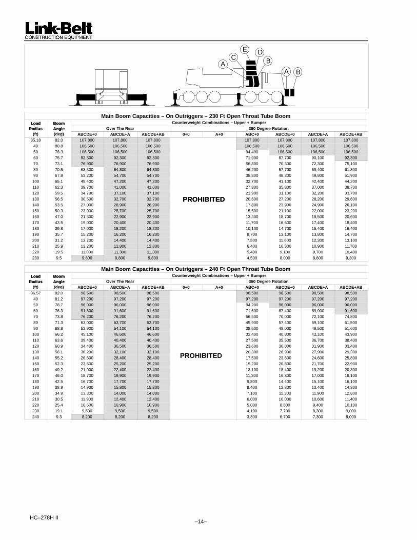
HC–278H II –14–
A BA
CE D
B
Main Boom Capacities – On Outriggers – 230 Ft Open Throat Tube BoomLoad Boom Counterweight Combinations – Upper + BumperLoad
RadiusBoomAngle Over The Rear 360 Degree RotationRadius
(ft)Angle(deg) ABCDE+0 ABCDE+A ABCDE+AB 0+0 A+0 ABC+0 ABCDE+0 ABCDE+A ABCDE+AB
35.18 82.0 107,800 107,800 107,800 107,800 107,800 107,800 107,80040 80.8 106,500 106,500 106,500 106,500 106,500 106,500 106,50050 78.3 106,500 106,500 106,500 94,400 106,500 106,500 106,50060 75.7 92,300 92,300 92,300 71,900 87,700 90,100 92,30070 73.1 76,900 76,900 76,900 56,800 70,300 72,300 75,10080 70.5 63,300 64,300 64,300 46,200 57,700 59,400 61,80090 67.8 53,200 54,700 54,700 38,800 48,300 49,800 51,900
100 65.1 45,400 47,200 47,200 32,700 41,100 42,400 44,200110 62.3 39,700 41,000 41,000 27,800 35,800 37,000 38,700120 59.5 34,700 37,100 37,100 23,900 31,100 32,200 33,700130 56.5 30,500 32,700 32,700 PROHIBITED 20,600 27,200 28,200 29,600140 53.5 27,000 28,900 28,900
PROHIBITED17,800 23,900 24,900 26,100
150 50.3 23,900 25,700 25,700 15,500 21,100 22,000 23,200160 47.0 21,300 22,900 22,900 13,400 18,700 19,500 20,600170 43.5 19,000 20,400 20,400 11,700 16,600 17,400 18,400180 39.8 17,000 18,200 18,200 10,100 14,700 15,400 16,400190 35.7 15,200 16,200 16,200 8,700 13,100 13,800 14,700200 31.2 13,700 14,400 14,400 7,500 11,600 12,300 13,100210 25.9 12,200 12,800 12,800 6,400 10,300 10,900 11,700220 19.5 11,000 11,300 11,300 5,400 9,100 9,700 10,400230 9.5 9,800 9,800 9,800 4,500 8,000 8,600 9,300
Main Boom Capacities – On Outriggers – 240 Ft Open Throat Tube BoomLoad Boom Counterweight Combinations – Upper + BumperLoad
RadiusBoomAngle Over The Rear 360 Degree RotationRadius
(ft)Angle(deg) ABCDE+0 ABCDE+A ABCDE+AB 0+0 A+0 ABC+0 ABCDE+0 ABCDE+A ABCDE+AB
36.57 82.0 98,500 98,500 98,500 98,500 98,500 98,500 98,50040 81.2 97,200 97,200 97,200 97,200 97,200 97,200 97,20050 78.7 96,000 96,000 96,000 94,200 96,000 96,000 96,00060 76.3 91,600 91,600 91,600 71,600 87,400 89,900 91,60070 73.8 76,200 76,200 76,200 56,500 70,000 72,100 74,80080 71.3 63,000 63,700 63,700 45,900 57,400 59,100 61,50090 68.8 52,900 54,100 54,100 38,500 48,000 49,500 51,600
100 66.2 45,100 46,600 46,600 32,400 40,800 42,100 43,900110 63.6 39,400 40,400 40,400 27,500 35,500 36,700 38,400120 60.9 34,400 36,500 36,500 23,600 30,800 31,900 33,400130 58.1 30,200 32,100 32,100 20,300 26,900 27,900 29,300140 55.2 26,600 28,400 28,400 PROHIBITED 17,500 23,600 24,600 25,800150 52.3 23,600 25,200 25,200 15,200 20,800 21,700 22,900160 49.2 21,000 22,400 22,400 13,100 18,400 19,200 20,300170 46.0 18,700 19,900 19,900 11,300 16,300 17,000 18,100180 42.5 16,700 17,700 17,700 9,800 14,400 15,100 16,100190 38.9 14,900 15,800 15,800 8,400 12,800 13,400 14,300200 34.9 13,300 14,000 14,000 7,100 11,300 11,900 12,800210 30.5 11,900 12,400 12,400 6,000 10,000 10,600 11,400220 25.4 10,600 10,900 10,900 5,000 8,800 9,400 10,100230 19.1 9,500 9,500 9,500 4,100 7,700 8,300 9,000240 9.3 8,200 8,200 8,200 3,300 6,700 7,300 8,000

–15– HC–278H II
A BA
CE D
B
Main Boom Capacities – On Outriggers – 250 Ft Open Throat Tube BoomLoad Boom Counterweight Combinations – Upper + BumperLoad
RadiusBoomAngle Over The Rear 360 Degree RotationRadius
(ft)Angle(deg) ABCDE+0 ABCDE+A ABCDE+AB 0+0 A+0 ABC+0 ABCDE+0 ABCDE+A ABCDE+AB
37.96 82.0 89,300 89,300 89,300 89,300 89,300 89,300 89,30040 81.5 89,300 89,300 89,300 89,300 89,300 89,300 89,30050 79.2 88,200 88,200 88,200 88,200 88,200 88,200 88,20060 76.9 87,100 87,100 87,100 71,400 87,100 87,100 87,10070 74.5 75,500 75,500 75,500 56,200 69,700 71,800 74,60080 72.1 62,700 63,000 63,000 45,600 57,100 58,800 61,20090 69.7 52,600 53,400 53,400 38,200 47,700 49,200 51,200
100 67.2 44,800 45,900 45,900 32,100 40,400 41,800 43,600110 64.7 39,100 39,800 39,800 27,200 35,200 36,400 38,000120 62.1 34,000 35,900 35,900 23,200 30,500 31,600 33,000130 59.5 29,800 31,500 31,500 19,900 26,600 27,600 28,900140 56.8 26,300 27,800 27,800 17,200 23,300 24,200 25,400150 54.0 23,200 24,400 24,400
PROHIBITED14,800 20,400 21,300 22,500
160 51.1 20,600 21,800 21,800 12,700 18,000 18,800 19,900170 48.1 18,300 19,300 19,300 10,900 15,900 16,600 17,600180 45.0 16,300 17,100 17,100 9,400 14,000 14,700 15,700190 41.6 14,500 15,200 15,200 8,000 12,400 13,000 13,900200 38.1 12,900 13,400 13,400 6,700 10,900 11,500 12,400210 34.2 11,500 11,800 11,800 5,600 9,500 10,100 11,000220 29.8 10,200 10,400 10,400 4,600 8,400 8,900 9,700230 24.9 9,000 9,000 9,000 3,700 7,300 7,800 8,500240 18.7 7,800 7,800 7,800 2,900 6,300 6,800 7,500250 9.1 6,500 6,500 6,500 2,100 5,400 5,900 6,500
Main Boom Capacities – On Outriggers – 260 Ft Open Throat Tube BoomLoad Boom Counterweight Combinations – Upper + BumperLoad
RadiusBoomAngle Over The Rear 360 Degree RotationRadius
(ft)Angle(deg) ABCDE+0 ABCDE+A ABCDE+AB 0+0 A+0 ABC+0 ABCDE+0 ABCDE+A ABCDE+AB
39.35 82.0 81,600 81,600 81,600 81,600 81,600 81,600 81,60040 81.9 81,600 81,600 81,600 81,600 81,600 81,600 81,60050 79.6 77,600 77,600 77,600 77,600 77,600 77,600 77,60060 77.4 76,600 76,600 76,600 71,100 76,600 76,600 76,60070 75.1 70,800 70,800 70,800 56,000 69,500 70,800 70,80080 72.8 62,400 62,400 62,400 45,300 56,800 58,500 60,90090 70.5 52,300 52,800 52,800 37,900 47,300 48,900 50,900
100 68.1 44,400 45,300 45,300 31,800 40,100 41,400 43,200110 65.7 38,800 40,200 40,200 26,900 34,900 36,100 37,700120 63.3 33,700 35,400 35,400 22,900 30,200 31,300 32,700130 60.8 29,500 31,000 31,000 19,600 26,200 27,200 28,600140 58.2 25,900 27,300 27,300 16,800 22,900 23,900 25,100150 55.6 22,900 24,100 24,100 PROHIBITED 14,500 20,100 21,000 22,100160 52.9 20,300 21,300 21,300 12,400 17,700 18,500 19,600170 50.1 18,000 18,800 18,800 10,600 15,600 16,300 17,300180 47.1 16,000 16,600 16,600 9,000 13,700 14,400 15,300190 44.1 14,200 14,700 14,700 7,600 12,000 12,700 13,600200 40.8 12,600 13,000 13,000 6,400 10,500 11,200 12,000210 37.3 11,200 11,400 11,400 5,300 9,200 9,800 10,600220 33.5 9,900 9,900 10,000 4,300 8,000 8,600 9,400230 29.3 8,600 8,600 8,600 3,400 6,900 7,500 8,200240 24.4 7,400 7,400 7,400 2,500 5,900 6,500 7,200250 18.3 6,300 6,300 6,300 – 5,000 5,500 6,200260 9.0 5,100 5,100 5,100 – 4,200 4,700 5,100

HC–278H II –16–
A BA
CE D
B
Main Boom Capacities – On Outriggers – 270 Ft Open Throat Tube BoomLoad Boom Counterweight Combinations – Upper + BumperLoad
RadiusBoomAngle Over The Rear 360 Degree RotationRadius
(ft)Angle(deg) ABCDE+0 ABCDE+A ABCDE+AB 0+0 A+0 ABC+0 ABCDE+0 ABCDE+A ABCDE+AB
40.74 82.0 71,700 71,700 71,700 71,700 71,700 71,700 71,70050 80.0 70,800 70,800 70,800 70,800 70,800 70,800 70,80060 77.8 69,900 69,900 69,900 69,900 69,900 69,900 69,90070 75.7 64,600 64,600 64,600 55,700 64,600 64,600 64,60080 73.5 59,800 59,800 59,800 45,000 56,500 58,200 59,80090 71.2 52,000 52,200 52,200 37,600 47,000 48,600 50,600
100 69.0 44,100 44,700 44,700 31,500 39,800 41,100 42,900110 66.7 38,500 40,000 40,000 26,600 34,600 35,800 37,400120 64.4 33,400 34,800 34,800 22,600 29,800 30,900 32,400130 62.0 29,200 30,500 30,400 19,300 25,900 26,900 28,300140 59.5 25,600 26,700 26,700 16,500 22,600 23,500 24,800150 57.1 22,600 23,500 23,600 14,100 19,800 20,700 21,800160 54.5 20,000 20,800 20,800 PROHIBITED 12,100 17,400 18,200 19,200170 51.8 17,700 18,300 18,300 10,300 15,200 16,000 17,000180 49.1 15,600 16,200 16,200 8,700 13,400 14,100 15,000190 46.2 13,800 14,200 14,200 7,300 11,700 12,400 13,300200 43.2 12,300 12,500 12,500 6,100 10,200 10,800 11,700210 40.0 10,800 10,900 10,900 4,900 8,900 9,500 10,300220 36.6 9,500 9,500 9,500 3,900 7,700 8,200 9,000230 32.8 8,200 8,200 8,200 3,000 6,600 7,100 7,900240 28.7 7,000 7,000 7,000 2,200 5,600 6,100 6,800250 23.9 5,900 5,900 5,900 – 4,700 5,200 5,900260 18.0 4,800 4,800 4,800 – 3,900 4,400 4,800270 8.8 3,800 3,800 3,800 – 3,100 3,600 3,800
Main Boom Capacities – On Outriggers – 280 Ft Open Throat Tube BoomLoad Boom Counterweight Combinations – Upper + BumperLoad
RadiusBoomAngle Over The Rear 360 Degree RotationRadius
(ft)Angle(deg) ABCDE+0 ABCDE+A ABCDE+AB 0+0 A+0 ABC+0 ABCDE+0 ABCDE+A ABCDE+AB
42.14 82.0 65,600 65,600 65,600 65,600 65,600 65,60050 80.4 64,800 64,800 64,800 64,800 64,800 64,80060 78.3 64,000 64,000 64,000 64,000 64,000 64,00070 76.2 59,200 59,200 59,200 59,200 59,200 59,20080 74.1 54,800 54,800 54,800 54,800 54,800 54,80090 71.9 50,000 50,000 50,000 46,700 48,200 50,000
100 69.8 43,800 44,100 44,100 40,100 40,800 42,600110 67.6 38,200 39,500 39,500 34,200 35,500 37,100120 65.3 33,100 34,300 34,300 29,500 30,600 32,100130 63.1 28,900 29,900 29,900 25,600 26,600 28,000140 60.7 25,300 26,200 26,200 22,300 23,200 24,500150 58.4 22,200 23,000 23,000 19,500 20,300 21,500160 55.9 19,600 20,300 20,300 PROHIBITED 17,000 17,800 18,900170 53.4 17,300 17,800 17,800
PROHIBITED14,900 15,600 16,700
180 50.8 15,300 15,700 15,700 13,000 13,700 14,700190 48.1 13,500 13,800 13,800 11,300 12,000 12,900200 45.3 11,900 12,000 12,000 9,900 10,500 11,300210 42.4 10,500 10,500 10,500 8,500 9,100 9,900220 39.2 9,100 9,000 9,100 7,300 7,900 8,700230 35.9 7,800 7,800 7,800 6,200 6,800 7,500240 32.2 6,600 6,600 6,600 5,300 5,800 6,500250 28.2 5,500 5,500 5,500 4,300 4,800 5,500260 23.5 4,400 4,400 4,400 3,500 4,000 4,400270 17.6 3,500 3,500 3,500 2,800 3,200 3,500280 8.6 2,500 2,500 2,500 2,100 2,500 2,500

–17– HC–278H II
A BA
CE D
B
Main Boom Capacities – On Outriggers – 290 Ft Open Throat Tube BoomLoad Boom Counterweight Combinations – Upper + BumperLoad
RadiusBoomAngle Over The Rear 360 Degree RotationRadius
(ft)Angle(deg) ABCDE+0 ABCDE+A ABCDE+AB 0+0 A+0 ABC+0 ABCDE+0 ABCDE+A ABCDE+AB
43.53 82.0 61,000 61,000 61,000 61,000 61,000 61,00050 80.7 60,200 60,200 60,200 60,200 60,200 60,20060 78.7 59,500 59,500 59,500 59,500 59,500 59,50070 76.7 55,000 55,000 55,000 55,000 55,000 55,00080 74.6 50,200 50,200 50,200 50,200 50,200 50,20090 72.6 46,400 46,400 46,400 46,400 46,400 46,400
100 70.5 42,400 42,400 42,400 39,700 40,400 42,300110 68.4 36,500 36,500 36,500 33,900 35,100 36,500120 66.2 32,800 33,700 33,700 29,200 30,300 31,800130 64.1 28,500 29,400 29,400 25,300 26,300 27,600140 61.8 25,000 25,700 25,700 22,000 22,900 24,100150 59.6 21,900 22,500 22,500 19,100 20,000 21,100160 57.3 19,300 19,800 19,800 16,700 17,500 18,600170 54.9 17,000 17,300 17,300
PROHIBITED14,500 15,300 16,300
180 52.4 15,000 15,200 15,200 12,700 13,400 14,300190 49.9 13,200 13,300 13,300 11,000 11,700 12,600200 47.3 11,500 11,500 11,600 9,500 10,100 11,000210 44.5 10,000 10,000 10,000 8,200 8,800 9,600220 41.6 8,600 8,600 8,600 7,000 7,600 8,300230 38.5 7,300 7,300 7,300 5,900 6,400 7,200240 35.2 6,100 6,100 6,100 4,900 5,400 6,100250 31.7 5,000 5,000 5,000 4,000 4,500 5,000260 27.7 4,000 4,000 4,000 3,200 3,600 4,000270 23.1 3,100 3,100 3,100 2,400 2,900 3,100280 17.3 2,200 2,200 2,200 – 2,200 2,200
Main Boom Capacities – On Outriggers – 300 Ft Open Throat Tube BoomLoad Boom Counterweight Combinations – Upper + BumperLoad
RadiusBoomAngle Over The Rear 360 Degree RotationRadius
(ft)Angle(deg) ABCDE+0 ABCDE+A ABCDE+AB 0+0 A+0 ABC+0 ABCDE+0 ABCDE+A ABCDE+AB
44.92 82.0 55,900 55,900 55,900 55,900 55,900 55,90050 81.0 55,500 55,500 55,500 55,500 55,500 55,50060 79.1 54,800 54,800 54,800 54,800 54,800 54,80070 77.1 50,400 50,400 50,400 50,400 50,400 50,40080 75.2 46,300 46,300 46,300 46,300 46,300 46,30090 73.2 42,500 42,500 42,500 42,500 42,500 42,500
100 71.2 36,100 36,100 36,100 36,100 36,100 36,100110 69.1 33,400 33,400 33,400 33,400 33,400 33,400120 67.1 30,900 30,900 30,900 28,900 30,000 30,900130 65.0 28,200 28,400 28,400 24,900 25,900 27,300140 62.9 24,600 25,200 25,200 21,600 22,500 23,800150 60.7 21,600 22,000 22,000 18,800 19,600 20,800160 58.5 18,900 19,200 19,200 PROHIBITED 16,300 17,100 18,200170 56.2 16,600 16,800 16,800 14,200 15,000 16,000180 53.9 14,600 14,700 14,700 12,300 13,000 14,000190 51.5 12,800 12,800 12,800 10,700 11,300 12,200200 49.0 11,100 11,100 11,100 9,200 9,800 10,600210 46.4 9,500 9,500 9,500 7,800 8,400 9,200220 43.7 8,100 8,100 8,100 6,600 7,200 8,000230 40.9 6,800 6,800 6,800 5,500 6,100 6,800240 37.9 5,700 5,700 5,700 4,500 5,100 5,700250 34.6 4,600 4,600 4,600 3,600 4,100 4,600260 31.1 3,600 3,600 3,600 2,800 3,300 3,600270 27.2 2,700 2,700 2,700 2,000 2,500 2,700

HC–278H II –18–
A BA
CE D
B
Main Boom Capacities – On Outriggers – 310 Ft Open Throat Tube BoomLoad Boom Counterweight Combinations – Upper + BumperLoad
RadiusBoomAngle Over The Rear 360 Degree RotationRadius
(ft)Angle(deg) ABCDE+0 ABCDE+A ABCDE+AB 0+0 A+0 ABC+0 ABCDE+0 ABCDE+A ABCDE+AB
46.31 82.0 51,500 51,500 51,500 51,50050 81.3 51,200 51,200 51,200 51,20060 79.4 50,600 50,600 50,600 50,60070 77.5 46,400 46,400 46,400 46,40080 75.6 42,700 42,700 42,700 42,70090 73.7 36,300 36,300 36,300 36,300
100 71.8 33,300 33,300 33,300 33,300110 69.8 30,800 30,800 30,800 30,800120 67.9 28,300 28,300 28,300 28,300130 65.8 E
D
26,200 26,200 25,600 26,200140 63.8 T
E
23,900 23,900 22,200 23,500150 61.7
IT
21,500 21,500 19,300 20,500160 59.6
IB
18,700 18,700 PROHIBITED 16,800 17,900170 57.4
H
16,300 16,300 14,600 15,600180 55.2
O
14,200 14,200 12,700 13,600190 52.9
R
12,300 12,300 11,000 11,900200 50.6
P
10,600 10,600 9,400 10,300210 48.1 9,000 9,000 8,100 8,900220 45.6 7,600 7,600 6,800 7,600230 43.0 6,400 6,400 5,700 6,400240 40.2 5,200 5,200 4,700 5,200250 37.2 4,100 4,100 3,800 4,100260 34.1 3,100 3,100 2,900 3,100270 30.6 2,200 2,200 2,100 2,200
Main Boom Capacities – On Outriggers – 320 Ft Open Throat Tube BoomLoad Boom Counterweight Combinations – Upper + BumperLoad
RadiusBoomAngle Over The Rear 360 Degree RotationRadius
(ft)Angle(deg) ABCDE+0 ABCDE+A ABCDE+AB 0+0 A+0 ABC+0 ABCDE+0 ABCDE+A ABCDE+AB
47.7 82.0 47,300 47,300 47,300 47,30050 81.6 47,300 47,300 47,300 47,30060 79.8 46,400 46,400 46,400 46,40070 77.9 42,900 42,900 42,900 42,90080 76.1 36,200 36,200 36,200 36,20090 74.3 33,500 33,500 33,500 33,500
100 72.4 30,500 30,500 30,500 30,500110 70.5 28,200 28,200 28,200 28,200120 68.6 D 25,900 25,900 25,900 25,900130 66.6
E
24,000 24,000 24,000 24,000140 64.7 IT 21,900 21,900 21,900 21,900150 62.7 IB 20,200 20,200 PROHIBITED 19,000 20,100160 60.7 H
I
18,200 18,200PROHIBITED
16,400 17,500170 58.6 O
H
15,800 15,800 14,200 15,300180 56.5 R
O
13,700 13,700 12,300 13,300190 54.3 P
R
11,800 11,800 10,600 11,500200 52.0
P
10,100 10,100 9,100 9,900210 49.7 8,500 8,500 7,700 8,500220 47.3 7,100 7,100 6,500 7,100230 44.9 5,900 5,900 5,300 5,900240 42.3 4,700 4,700 4,300 4,700250 39.5 3,600 3,600 3,400 3,700260 36.6 2,700 2,700 2,500 2,700
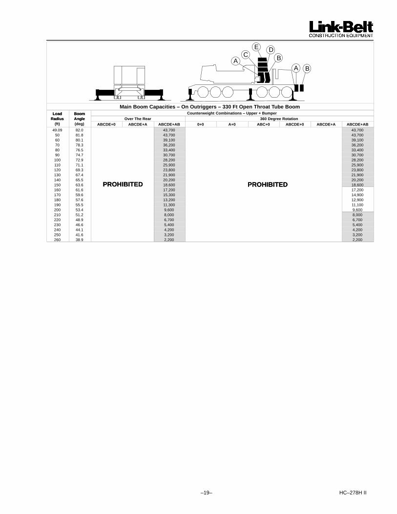
–19– HC–278H II
A BA
CE D
B
Main Boom Capacities – On Outriggers – 330 Ft Open Throat Tube BoomLoad Boom Counterweight Combinations – Upper + BumperLoad
RadiusBoomAngle Over The Rear 360 Degree RotationRadius
(ft)Angle(deg) ABCDE+0 ABCDE+A ABCDE+AB 0+0 A+0 ABC+0 ABCDE+0 ABCDE+A ABCDE+AB
49.09 82.0 43,700 43,70050 81.8 43,700 43,70060 80.1 39,100 39,10070 78.3 36,200 36,20080 76.5 33,400 33,40090 74.7 30,700 30,700
100 72.9 28,200 28,200110 71.1 25,900 25,900120 69.3 23,800 23,800130 67.4 21,900 21,900140 65.5 20,200 20,200150 63.6 PROHIBITED 18,600 PROHIBITED 18,600160 61.6
PROHIBITED17,200
PROHIBITED17,200
170 59.6 15,300 14,900180 57.6 13,200 12,900190 55.5 11,300 11,100200 53.4 9,600 9,600210 51.2 8,000 8,000220 48.9 6,700 6,700230 46.6 5,400 5,400240 44.1 4,200 4,200250 41.6 3,200 3,200260 38.9 2,200 2,200

HC–278H II –20–
Link–Belt Construction Equipment Company Lexington, Kentucky www.linkbelt.com� Link–Belt is a registered trademark. Copyright 2005. All rights reserved. We are constantly improving our products and therefore reserve the right to change designs and specifications.
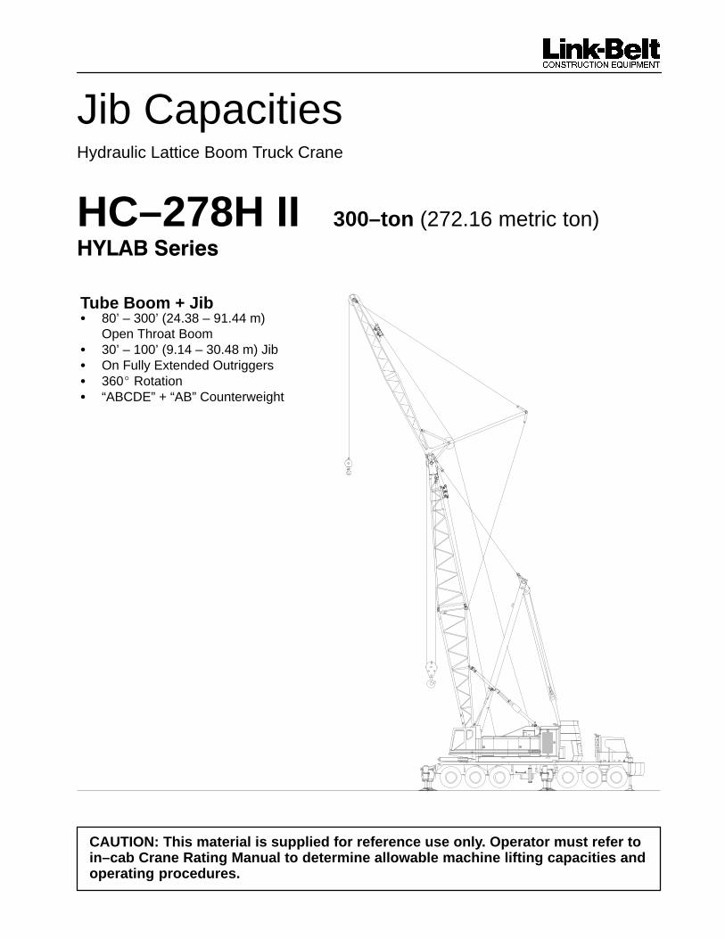
Jib CapacitiesHydraulic Lattice Boom Truck Crane
HC–278H II 300–ton (272.16 metric ton)����������
Tube Boom + Jib� 80’ – 300’ (24.38 – 91.44 m)
Open Throat Boom� 30’ – 100’ (9.14 – 30.48 m) Jib� On Fully Extended Outriggers� 360� Rotation� “ABCDE” + “AB” Counterweight
CAUTION: This material is supplied for reference use only. Operator must refer toin–cab Crane Rating Manual to determine allowable machine lifting capacities andoperating procedures.

HC–278H II
TUBULAR JIB NOTES FOR OPEN THROAT BOOM
1. Capacities are for an HC 278H II truck crane with ABCDE+AB (134,900 lb) counterweight.
2. Capacities are for truck crane working areas for 360�, described on the Working Area Chart found in theSpecifications Section of the Crane Rating Manual and are based on crane standing level on firm supportingsurface and front bumper outrigger properly extended (crane on 5 jacks).
3. Capacities are limited to an LBCE 68” x 80” tubular boom with an open throat and LBCE 30 ton 24” x 32”cross–section jib with a 17’10” high jib mast properly assembled.
4. Two parts of 1.00” or 1–1/8’’ Diameter Type ”N” or Type ”RB” wire rope are required for maximum lift.
5. Capacities are for 30’ – 100’ jib lengths .
6. A jib cannot be used on open throat boom lengths longer than 300’.
7. The least stable rated condition is over the side.
8. All capacities are in pounds and are not more than 85% of the tipping loads. Those capacities followed by anasterisk (*) are governed by factors other than those that would cause a tipping condition.
9. A deduction must be made from the jib capacities for the weight of the following: Main boom hook block or hookball, jib hook block or hook ball, slings, grapple, load weighing devices, etc.
10. For jibs on booms 60’ thru 260’ use either ABCDE+0 or ABCDE+AB counterweight as capacities are includedfor both counterweight combinations. Crane must be on outriggers with front bumper outrigger properlyextended.
11. For jibs on booms 270’ thru 300’ use ABCDE+AB counterweight. Crane must be on outriggers with front bumperoutrigger properly extended.
����������������� ������� ��� ��
A BA
C
E D
B
5�
25� 15�
����������������� ��������������
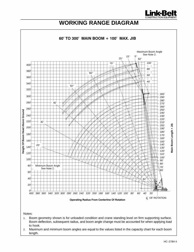
HC–278H II
WORKING RANGE DIAGRAMH
eig
ht
Of
Bo
om
Hea
d A
bo
ve G
rou
nd
� ������ ���������������� �����������
���������� !��"#$�%����&����'��#���#�
Notes:1. Boom geometry shown is for unloaded condition and crane standing level on firm supporting surface.
Boom deflection, subsequent radius, and boom angle change must be accounted for when applying loadto hook.
2. Maximum and minimum boom angles are equal to the values listed in the capacity chart for each boomlength.
Mai
n B
oo
m L
eng
th +
Jib
Maximum Boom AngleSee Note 2.
Minimum Boom AngleSee Note 2.
300’290’280’270’260’250’240’230’220’210’200’190’180’170’160’150’140’130’120’110’100’90’80’70’60’
320’
300’
280’
260’
240’
220’
200’
180’
160’
140’
120’
100’
80’
60’
40’
20’
0’
340’
70�
60�
50�
40�
30�
20�
320’ 300’ 280’ 260’ 240’ 220’ 200’ 180’ 160’ 140’ 120’ 100’ 80’ 60’ 40’ 20’
CL OF ROTATION
82�
340’360’380’400’
360’
380’
400’
25�5�15�
100’
80’
60’
40’
82�

Boom Jib Pt Jib Capacity Boom Jib Pt Jib Capacity Boom Jib Pt Jib CapacityAngle Height ABCDE + AB Angle Height ABCDE + AB Angle Height ABCDE + AB(deg) (ft) (lbs) (deg) (ft) (lbs) (deg) (ft) (lbs)
80 30 21.4 82.0 118.1 60,00080 30 25.0 80.1 117.5 60,00080 30 30.0 77.5 116.4 60,000 80.1 115.7 58,00080 30 35.0 74.9 115.0 60,000 77.4 114.3 57,000 79.8 112.9 47,80080 30 40.0 72.2 113.4 59,000 74.7 112.7 56,100 77.1 111.3 44,50080 30 50.0 66.7 109.4 56,900 69.2 108.7 50,800 71.5 107.2 39,20080 30 60.0 60.9 104.2 53,400 63.4 103.4 44,000 65.6 101.9 37,00080 30 70.0 54.8 97.6 45,500 57.2 96.7 38,900 59.3 95.1 36,10080 30 80.0 48.2 89.2 39,600 50.5 88.3 37,000 52.5 86.5 33,10080 30 90.0 40.7 78.6 37,100 42.9 77.5 35,80080 30 100.0 31.8 64.2 35,300
80 50 25.9 82.0 137.6 43,80080 50 30.0 80.2 136.8 42,90080 50 35.0 78.0 135.7 41,900 81.6 134.7 39,50080 50 40.0 75.7 134.4 41,000 79.4 133.4 38,70080 50 50.0 71.2 131.0 39,300 74.8 130.0 34,800 78.2 128.0 28,40080 50 60.0 66.4 126.8 37,900 70.0 125.7 33,100 73.4 123.6 25,20080 50 70.0 61.5 121.5 34,100 65.1 120.4 29,000 68.3 118.2 22,70080 50 80.0 56.4 115.0 31,100 59.9 113.8 25,900 63.0 111.5 20,80080 50 90.0 50.9 107.1 27,400 54.3 105.8 23,400 57.3 103.3 19,20080 50 100.0 44.8 97.4 24,500 48.2 96.0 21,400 51.0 93.2 17,90080 50 110.0 38.0 85.3 22,100 41.2 83.7 19,90080 50 120.0 29.9 69.4 20,200
80 70 30.4 82.0 157.1 29,40080 70 35.0 80.2 156.2 28,80080 70 40.0 78.3 155.0 28,30080 70 50.0 74.4 152.2 27,300 78.8 151.0 26,00080 70 60.0 70.4 148.6 26,300 74.8 147.3 24,900 79.0 144.8 18,80080 70 70.0 66.3 144.1 25,500 70.6 142.8 21,800 74.8 140.3 16,90080 70 80.0 62.0 138.8 24,600 66.3 137.4 19,400 70.4 134.8 15,30080 70 90.0 57.5 132.4 21,700 61.8 131.0 17,500 65.8 128.2 14,10080 70 100.0 52.8 124.8 19,400 57.0 123.3 16,000 60.9 120.3 13,00080 70 110.0 47.7 115.8 17,500 51.9 114.2 14,700 55.6 110.9 12,20080 70 120.0 42.2 104.9 16,000 46.3 103.1 13,600 49.7 99.5 11,50080 70 130.0 35.9 91.6 14,700 39.8 89.5 12,80080 70 140.0 28.3 74.1 13,700
80 90 34.9 82.0 176.6 18,70080 90 35.0 82.0 176.6 18,70080 90 40.0 80.3 175.6 18,10080 90 50.0 76.8 173.1 16,900 81.9 171.7 15,40080 90 60.0 73.3 169.9 15,900 78.4 168.5 14,50080 90 70.0 69.8 166.1 14,900 74.8 164.6 13,600 79.7 161.8 12,60080 90 80.0 66.1 161.5 14,000 71.1 160.0 12,900 75.9 157.1 11,90080 90 90.0 62.3 156.1 13,100 67.3 154.5 12,100 72.0 151.5 11,10080 90 100.0 58.4 149.8 12,400 63.3 148.2 11,500 67.9 145.0 10,20080 90 110.0 54.3 142.4 11,600 59.2 140.7 10,900 63.7 137.4 9,50080 90 120.0 49.9 133.9 11,000 54.7 132.1 10,300 59.1 128.5 8,80080 90 130.0 45.2 123.8 10,400 49.9 121.9 9,900 54.2 118.0 8,30080 90 140.0 40.0 111.9 9,900 44.7 109.8 9,400 48.7 105.3 7,80080 90 150.0 34.1 97.4 9,500 38.6 94.8 8,80080 90 160.0 27.0 78.5 9,100
80 100 37.1 82.0 186.3 13,80080 100 40.0 81.1 185.8 13,50080 100 50.0 77.9 183.4 12,50080 100 60.0 74.6 180.4 11,500 79.9 179.0 10,30080 100 70.0 71.2 176.8 10,600 76.5 175.4 9,500 81.7 172.4 8,60080 100 80.0 67.8 172.5 9,800 73.1 171.0 8,800 78.2 168.0 8,00080 100 90.0 64.3 167.5 9,100 69.5 166.0 8,200 74.6 162.8 7,40080 100 100.0 60.6 161.7 8,400 65.9 160.1 7,600 70.8 156.8 6,90080 100 110.0 56.9 154.9 7,800 62.0 153.2 7,100 66.9 149.8 6,500
HC-278H II - w/ 68" x 80" Tube Boom, w/ 24" x 32" Tube Jib, w/ ABCDE + AB Ctwt - 360 Degree RotationRefer to the Tubular Jib Notes for Open Throat Boom in the Crane Rating Manual before operating the machine.
Boom Length
(ft)
Jib Length
(ft)
Jib Load
Radius (ft)
5 Degrees 15 Degrees 25 Degrees
Jib Angle to Boom
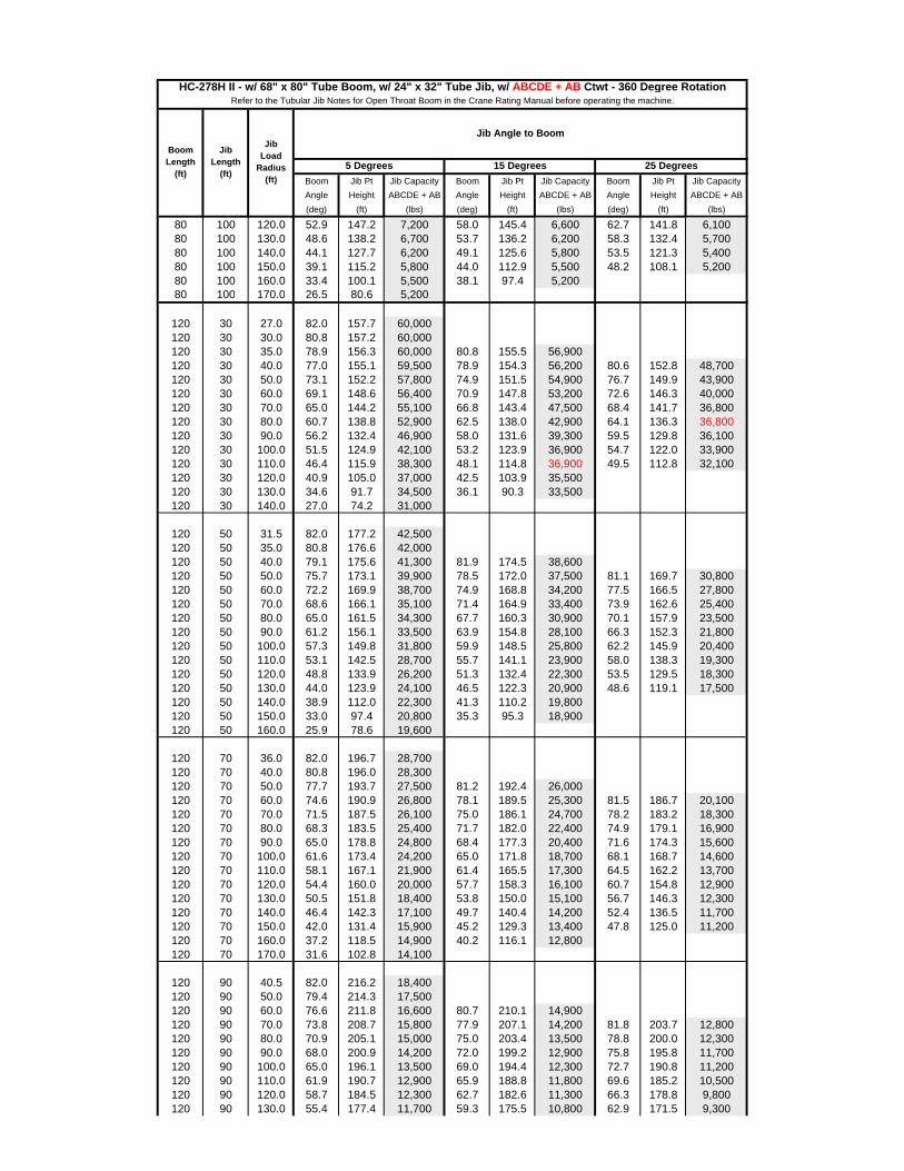
Boom Jib Pt Jib Capacity Boom Jib Pt Jib Capacity Boom Jib Pt Jib CapacityAngle Height ABCDE + AB Angle Height ABCDE + AB Angle Height ABCDE + AB(deg) (ft) (lbs) (deg) (ft) (lbs) (deg) (ft) (lbs)
HC-278H II - w/ 68" x 80" Tube Boom, w/ 24" x 32" Tube Jib, w/ ABCDE + AB Ctwt - 360 Degree RotationRefer to the Tubular Jib Notes for Open Throat Boom in the Crane Rating Manual before operating the machine.
Boom Length
(ft)
Jib Length
(ft)
Jib Load
Radius (ft)
5 Degrees 15 Degrees 25 Degrees
Jib Angle to Boom
80 100 120.0 52.9 147.2 7,200 58.0 145.4 6,600 62.7 141.8 6,10080 100 130.0 48.6 138.2 6,700 53.7 136.2 6,200 58.3 132.4 5,70080 100 140.0 44.1 127.7 6,200 49.1 125.6 5,800 53.5 121.3 5,40080 100 150.0 39.1 115.2 5,800 44.0 112.9 5,500 48.2 108.1 5,20080 100 160.0 33.4 100.1 5,500 38.1 97.4 5,20080 100 170.0 26.5 80.6 5,200
120 30 27.0 82.0 157.7 60,000120 30 30.0 80.8 157.2 60,000120 30 35.0 78.9 156.3 60,000 80.8 155.5 56,900120 30 40.0 77.0 155.1 59,500 78.9 154.3 56,200 80.6 152.8 48,700120 30 50.0 73.1 152.2 57,800 74.9 151.5 54,900 76.7 149.9 43,900120 30 60.0 69.1 148.6 56,400 70.9 147.8 53,200 72.6 146.3 40,000120 30 70.0 65.0 144.2 55,100 66.8 143.4 47,500 68.4 141.7 36,800120 30 80.0 60.7 138.8 52,900 62.5 138.0 42,900 64.1 136.3 36,800120 30 90.0 56.2 132.4 46,900 58.0 131.6 39,300 59.5 129.8 36,100120 30 100.0 51.5 124.9 42,100 53.2 123.9 36,900 54.7 122.0 33,900120 30 110.0 46.4 115.9 38,300 48.1 114.8 36,900 49.5 112.8 32,100120 30 120.0 40.9 105.0 37,000 42.5 103.9 35,500120 30 130.0 34.6 91.7 34,500 36.1 90.3 33,500120 30 140.0 27.0 74.2 31,000
120 50 31.5 82.0 177.2 42,500120 50 35.0 80.8 176.6 42,000120 50 40.0 79.1 175.6 41,300 81.9 174.5 38,600120 50 50.0 75.7 173.1 39,900 78.5 172.0 37,500 81.1 169.7 30,800120 50 60.0 72.2 169.9 38,700 74.9 168.8 34,200 77.5 166.5 27,800120 50 70.0 68.6 166.1 35,100 71.4 164.9 33,400 73.9 162.6 25,400120 50 80.0 65.0 161.5 34,300 67.7 160.3 30,900 70.1 157.9 23,500120 50 90.0 61.2 156.1 33,500 63.9 154.8 28,100 66.3 152.3 21,800120 50 100.0 57.3 149.8 31,800 59.9 148.5 25,800 62.2 145.9 20,400120 50 110.0 53.1 142.5 28,700 55.7 141.1 23,900 58.0 138.3 19,300120 50 120.0 48.8 133.9 26,200 51.3 132.4 22,300 53.5 129.5 18,300120 50 130.0 44.0 123.9 24,100 46.5 122.3 20,900 48.6 119.1 17,500120 50 140.0 38.9 112.0 22,300 41.3 110.2 19,800120 50 150.0 33.0 97.4 20,800 35.3 95.3 18,900120 50 160.0 25.9 78.6 19,600
120 70 36.0 82.0 196.7 28,700120 70 40.0 80.8 196.0 28,300120 70 50.0 77.7 193.7 27,500 81.2 192.4 26,000120 70 60.0 74.6 190.9 26,800 78.1 189.5 25,300 81.5 186.7 20,100120 70 70.0 71.5 187.5 26,100 75.0 186.1 24,700 78.2 183.2 18,300120 70 80.0 68.3 183.5 25,400 71.7 182.0 22,400 74.9 179.1 16,900120 70 90.0 65.0 178.8 24,800 68.4 177.3 20,400 71.6 174.3 15,600120 70 100.0 61.6 173.4 24,200 65.0 171.8 18,700 68.1 168.7 14,600120 70 110.0 58.1 167.1 21,900 61.4 165.5 17,300 64.5 162.2 13,700120 70 120.0 54.4 160.0 20,000 57.7 158.3 16,100 60.7 154.8 12,900120 70 130.0 50.5 151.8 18,400 53.8 150.0 15,100 56.7 146.3 12,300120 70 140.0 46.4 142.3 17,100 49.7 140.4 14,200 52.4 136.5 11,700120 70 150.0 42.0 131.4 15,900 45.2 129.3 13,400 47.8 125.0 11,200120 70 160.0 37.2 118.5 14,900 40.2 116.1 12,800120 70 170.0 31.6 102.8 14,100
120 90 40.5 82.0 216.2 18,400120 90 50.0 79.4 214.3 17,500120 90 60.0 76.6 211.8 16,600 80.7 210.1 14,900120 90 70.0 73.8 208.7 15,800 77.9 207.1 14,200 81.8 203.7 12,800120 90 80.0 70.9 205.1 15,000 75.0 203.4 13,500 78.8 200.0 12,300120 90 90.0 68.0 200.9 14,200 72.0 199.2 12,900 75.8 195.8 11,700120 90 100.0 65.0 196.1 13,500 69.0 194.4 12,300 72.7 190.8 11,200120 90 110.0 61.9 190.7 12,900 65.9 188.8 11,800 69.6 185.2 10,500120 90 120.0 58.7 184.5 12,300 62.7 182.6 11,300 66.3 178.8 9,800120 90 130.0 55.4 177.4 11,700 59.3 175.5 10,800 62.9 171.5 9,300
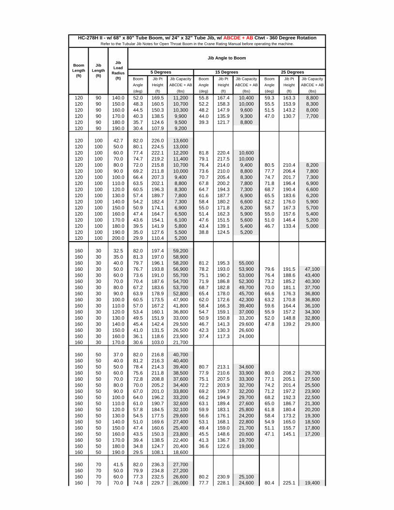
Boom Jib Pt Jib Capacity Boom Jib Pt Jib Capacity Boom Jib Pt Jib CapacityAngle Height ABCDE + AB Angle Height ABCDE + AB Angle Height ABCDE + AB(deg) (ft) (lbs) (deg) (ft) (lbs) (deg) (ft) (lbs)
HC-278H II - w/ 68" x 80" Tube Boom, w/ 24" x 32" Tube Jib, w/ ABCDE + AB Ctwt - 360 Degree RotationRefer to the Tubular Jib Notes for Open Throat Boom in the Crane Rating Manual before operating the machine.
Boom Length
(ft)
Jib Length
(ft)
Jib Load
Radius (ft)
5 Degrees 15 Degrees 25 Degrees
Jib Angle to Boom
120 90 140.0 52.0 169.5 11,200 55.8 167.4 10,400 59.3 163.3 8,800120 90 150.0 48.3 160.5 10,700 52.2 158.3 10,000 55.5 153.9 8,300120 90 160.0 44.5 150.3 10,300 48.2 147.9 9,600 51.5 143.2 8,000120 90 170.0 40.3 138.5 9,900 44.0 135.9 9,300 47.0 130.7 7,700120 90 180.0 35.7 124.6 9,500 39.3 121.7 8,800120 90 190.0 30.4 107.9 9,200
120 100 42.7 82.0 226.0 13,600120 100 50.0 80.1 224.5 13,000120 100 60.0 77.4 222.1 12,200 81.8 220.4 10,600120 100 70.0 74.7 219.2 11,400 79.1 217.5 10,000120 100 80.0 72.0 215.8 10,700 76.4 214.0 9,400 80.5 210.4 8,200120 100 90.0 69.2 211.8 10,000 73.6 210.0 8,800 77.7 206.4 7,800120 100 100.0 66.4 207.3 9,400 70.7 205.4 8,300 74.7 201.7 7,300120 100 110.0 63.5 202.1 8,800 67.8 200.2 7,800 71.8 196.4 6,900120 100 120.0 60.5 196.3 8,300 64.7 194.3 7,300 68.7 190.4 6,600120 100 130.0 57.4 189.7 7,800 61.6 187.7 6,900 65.5 183.6 6,200120 100 140.0 54.2 182.4 7,300 58.4 180.2 6,600 62.2 176.0 5,900120 100 150.0 50.9 174.1 6,900 55.0 171.8 6,200 58.7 167.3 5,700120 100 160.0 47.4 164.7 6,500 51.4 162.3 5,900 55.0 157.6 5,400120 100 170.0 43.6 154.1 6,100 47.6 151.5 5,600 51.0 146.4 5,200120 100 180.0 39.5 141.9 5,800 43.4 139.1 5,400 46.7 133.4 5,000120 100 190.0 35.0 127.6 5,500 38.8 124.5 5,200120 100 200.0 29.9 110.4 5,200
160 30 32.5 82.0 197.4 59,200160 30 35.0 81.3 197.0 58,900160 30 40.0 79.7 196.1 58,200 81.2 195.3 55,000160 30 50.0 76.7 193.8 56,900 78.2 193.0 53,900 79.6 191.5 47,100160 30 60.0 73.6 191.0 55,700 75.1 190.2 53,000 76.4 188.6 43,400160 30 70.0 70.4 187.6 54,700 71.9 186.8 52,300 73.2 185.2 40,300160 30 80.0 67.2 183.6 53,700 68.7 182.8 49,700 70.0 181.1 37,700160 30 90.0 63.9 178.9 52,800 65.4 178.0 45,700 66.6 176.3 36,800160 30 100.0 60.5 173.5 47,900 62.0 172.6 42,300 63.2 170.8 36,800160 30 110.0 57.0 167.2 41,800 58.4 166.3 39,400 59.6 164.4 36,100160 30 120.0 53.4 160.1 36,800 54.7 159.1 37,000 55.9 157.2 34,300160 30 130.0 49.5 151.9 33,000 50.9 150.8 33,200 52.0 148.8 32,800160 30 140.0 45.4 142.4 29,500 46.7 141.3 29,600 47.8 139.2 29,800160 30 150.0 41.0 131.5 26,500 42.3 130.3 26,600160 30 160.0 36.1 118.6 23,900 37.4 117.3 24,000160 30 170.0 30.6 103.0 21,700
160 50 37.0 82.0 216.8 40,700160 50 40.0 81.2 216.3 40,400160 50 50.0 78.4 214.3 39,400 80.7 213.1 34,600160 50 60.0 75.6 211.8 38,500 77.9 210.6 33,900 80.0 208.2 29,700160 50 70.0 72.8 208.8 37,600 75.1 207.5 33,300 77.1 205.1 27,500160 50 80.0 70.0 205.2 34,400 72.2 203.9 32,700 74.2 201.4 25,500160 50 90.0 67.0 201.0 33,800 69.2 199.7 32,200 71.2 197.2 23,900160 50 100.0 64.0 196.2 33,200 66.2 194.9 29,700 68.2 192.3 22,500160 50 110.0 61.0 190.7 32,600 63.1 189.4 27,600 65.0 186.7 21,300160 50 120.0 57.8 184.5 32,100 59.9 183.1 25,800 61.8 180.4 20,200160 50 130.0 54.5 177.5 29,600 56.6 176.1 24,200 58.4 173.2 19,300160 50 140.0 51.0 169.6 27,400 53.1 168.1 22,800 54.9 165.0 18,500160 50 150.0 47.4 160.6 25,400 49.4 159.0 21,700 51.1 155.7 17,800160 50 160.0 43.5 150.3 23,800 45.5 148.6 20,600 47.1 145.1 17,200160 50 170.0 39.4 138.5 22,400 41.3 136.7 19,700160 50 180.0 34.8 124.7 20,400 36.6 122.6 19,000160 50 190.0 29.5 108.1 18,600
160 70 41.5 82.0 236.3 27,700160 70 50.0 79.9 234.8 27,200160 70 60.0 77.3 232.5 26,600 80.2 230.9 25,100160 70 70.0 74.8 229.7 26,000 77.7 228.1 24,600 80.4 225.1 19,400

Boom Jib Pt Jib Capacity Boom Jib Pt Jib Capacity Boom Jib Pt Jib CapacityAngle Height ABCDE + AB Angle Height ABCDE + AB Angle Height ABCDE + AB(deg) (ft) (lbs) (deg) (ft) (lbs) (deg) (ft) (lbs)
HC-278H II - w/ 68" x 80" Tube Boom, w/ 24" x 32" Tube Jib, w/ ABCDE + AB Ctwt - 360 Degree RotationRefer to the Tubular Jib Notes for Open Throat Boom in the Crane Rating Manual before operating the machine.
Boom Length
(ft)
Jib Length
(ft)
Jib Load
Radius (ft)
5 Degrees 15 Degrees 25 Degrees
Jib Angle to Boom
160 70 80.0 72.2 226.4 25,500 75.1 224.9 24,200 77.7 221.7 18,000160 70 90.0 69.5 222.7 25,000 72.4 221.1 22,800 75.1 217.9 16,800160 70 100.0 66.9 218.4 24,500 69.7 216.7 21,100 72.3 213.5 15,800160 70 110.0 64.1 213.5 24,100 66.9 211.8 19,600 69.5 208.5 14,900160 70 120.0 61.3 208.0 23,700 64.1 206.3 18,300 66.6 202.8 14,100160 70 130.0 58.4 201.8 22,000 61.2 200.1 17,100 63.6 196.5 13,400160 70 140.0 55.4 194.9 20,400 58.1 193.1 16,200 60.5 189.4 12,800160 70 150.0 52.3 187.2 19,000 55.0 185.3 15,300 57.3 181.4 12,300160 70 160.0 49.0 178.6 17,800 51.7 176.5 14,500 54.0 172.5 11,800160 70 170.0 45.6 168.8 16,800 48.2 166.7 13,800 50.4 162.4 11,400160 70 180.0 41.9 157.8 15,800 44.5 155.5 13,200 46.5 150.9 11,000160 70 190.0 37.9 145.2 15,000 40.4 142.7 12,700160 70 200.0 33.6 130.5 14,300 36.0 127.7 12,300160 70 210.0 28.6 112.9 13,600
160 90 46.0 82.0 255.8 17,800160 90 50.0 81.1 255.1 17,700160 90 60.0 78.8 253.0 17,000160 90 70.0 76.4 250.5 16,300 79.9 248.6 14,500160 90 80.0 74.0 247.5 15,600 77.5 245.7 13,900 80.7 242.0 12,400160 90 90.0 71.6 244.1 14,900 75.0 242.2 13,300 78.3 238.5 12,000160 90 100.0 69.2 240.2 14,300 72.6 238.2 12,800 75.8 234.4 11,600160 90 110.0 66.7 235.7 13,700 70.1 233.8 12,300 73.2 229.9 11,200160 90 120.0 64.2 230.8 13,200 67.5 228.8 11,900 70.6 224.8 10,600160 90 130.0 61.6 225.3 12,700 64.9 223.2 11,400 68.0 219.2 10,000160 90 140.0 58.9 219.1 12,200 62.2 217.0 11,000 65.2 212.8 9,500160 90 150.0 56.2 212.3 11,700 59.4 210.2 10,700 62.4 205.8 9,100160 90 160.0 53.3 204.8 11,300 56.6 202.5 10,300 59.4 198.0 8,700160 90 170.0 50.4 196.4 10,800 53.6 194.1 10,000 56.4 189.3 8,400160 90 180.0 47.3 187.1 10,500 50.4 184.6 9,700 53.1 179.6 8,100160 90 190.0 44.0 176.7 10,100 47.1 174.1 9,400 49.7 168.7 7,800160 90 200.0 40.5 165.0 9,800 43.5 162.1 9,100 46.0 156.4 7,600160 90 210.0 36.7 151.6 9,500 39.7 148.5 8,800160 90 220.0 32.5 136.1 9,200 35.4 132.6 8,500160 90 230.0 27.7 117.5 9,000
160 100 48.3 82.0 265.6 13,300160 100 50.0 81.6 265.3 13,200160 100 60.0 79.4 263.2 12,500160 100 70.0 77.1 260.8 11,900 80.8 258.9 10,200160 100 80.0 74.9 258.0 11,200 78.5 256.0 9,700160 100 90.0 72.6 254.7 10,700 76.2 252.7 9,200 79.7 248.7 8,000160 100 100.0 70.2 250.9 10,100 73.9 248.9 8,700 77.3 244.9 7,600160 100 110.0 67.9 246.7 9,600 71.5 244.7 8,300 74.9 240.5 7,200160 100 120.0 65.4 242.0 9,100 69.0 239.9 7,900 72.4 235.7 6,900160 100 130.0 63.0 236.8 8,600 66.5 234.6 7,500 69.9 230.3 6,600160 100 140.0 60.4 230.9 8,100 64.0 228.7 7,100 67.2 224.3 6,300160 100 150.0 57.8 224.5 7,700 61.4 222.2 6,800 64.6 217.7 6,000160 100 160.0 55.2 217.4 7,300 58.7 215.0 6,500 61.8 210.3 5,800160 100 170.0 52.4 209.5 7,000 55.8 207.1 6,200 58.9 202.2 5,600160 100 180.0 49.5 200.9 6,600 52.9 198.3 5,900 55.9 193.2 5,400160 100 190.0 46.5 191.2 6,300 49.8 188.5 5,700 52.7 183.1 5,200160 100 200.0 43.2 180.5 6,000 46.6 177.6 5,500 49.4 171.8 5,100160 100 210.0 39.8 168.4 5,700 43.1 165.3 5,300 45.8 159.1 4,900160 100 220.0 36.1 154.7 5,500 39.3 151.3 5,100160 100 230.0 32.0 138.8 5,300 35.1 135.0 5,000160 100 240.0 27.3 119.8 5,100
200 30 38.1 82.0 237.0 55,400200 30 40.0 81.5 236.7 55,100200 30 50.0 79.0 234.8 54,100 80.3 234.0 51,500 81.4 232.4 49,500200 30 60.0 76.5 232.6 53,200 77.7 231.7 50,700 78.9 230.1 46,000
Boom Jib Pt Jib Capacity Boom Jib Pt Jib Capacity Boom Jib Pt Jib CapacityAngle Height ABCDE + AB Angle Height ABCDE + AB Angle Height ABCDE + AB(deg) (ft) (lbs) (deg) (ft) (lbs) (deg) (ft) (lbs)
HC-278H II - w/ 68" x 80" Tube Boom, w/ 24" x 32" Tube Jib, w/ ABCDE + AB Ctwt - 360 Degree RotationRefer to the Tubular Jib Notes for Open Throat Boom in the Crane Rating Manual before operating the machine.
Boom Length
(ft)
Jib Length
(ft)
Jib Load
Radius (ft)
5 Degrees 15 Degrees 25 Degrees
Jib Angle to Boom
200 30 70.0 73.9 229.8 52,300 75.1 229.0 50,000 76.3 227.3 43,100200 30 80.0 71.3 226.5 51,500 72.5 225.7 49,400 73.6 224.0 40,500200 30 90.0 68.7 222.8 50,700 69.9 221.9 48,800 71.0 220.2 38,300200 30 100.0 66.0 218.5 46,200 67.2 217.6 46,800 68.3 215.9 36,300200 30 110.0 63.3 213.6 40,100 64.4 212.7 40,500 65.5 210.9 36,300200 30 120.0 60.5 208.1 35,500 61.6 207.2 35,900 62.6 205.4 36,300200 30 130.0 57.6 201.9 31,300 58.7 201.0 31,600 59.7 199.1 32,000200 30 140.0 54.6 195.0 27,800 55.7 194.1 28,100 56.6 192.1 28,400200 30 150.0 51.4 187.3 24,800 52.6 186.3 25,000 53.5 184.3 25,300200 30 160.0 48.2 178.7 22,200 49.3 177.6 22,400 50.2 175.5 22,600200 30 170.0 44.7 169.0 20,000 45.8 167.8 20,100 46.7 165.6 20,300200 30 180.0 41.1 158.0 18,000 42.1 156.7 18,100200 30 190.0 37.1 145.4 16,200 38.1 144.0 16,300200 30 200.0 32.7 130.7 14,600200 30 210.0 27.7 113.1 13,200
200 50 42.6 82.0 256.5 38,500200 50 50.0 80.3 255.2 37,900200 50 60.0 78.0 253.1 34,800 79.9 251.8 32,900 81.7 249.3 31,200200 50 70.0 75.6 250.5 34,800 77.5 249.3 32,400 79.3 246.8 29,000200 50 80.0 73.3 247.6 33,600 75.1 246.3 31,900 76.9 243.8 27,200200 50 90.0 70.9 244.1 33,100 72.7 242.8 31,500 74.4 240.3 25,600200 50 100.0 68.4 240.2 32,600 70.3 238.9 31,000 72.0 236.3 24,200200 50 110.0 65.9 235.8 32,100 67.8 234.5 30,600 69.4 231.8 23,000200 50 120.0 63.4 230.9 31,600 65.2 229.5 28,900 66.8 226.8 21,900200 50 130.0 60.8 225.4 31,200 62.6 223.9 27,200 64.2 221.1 20,900200 50 140.0 58.1 219.2 28,600 59.9 217.8 25,700 61.5 214.9 20,000200 50 150.0 55.4 212.4 25,500 57.2 210.9 24,400 58.7 207.9 19,300200 50 160.0 52.5 204.9 22,900 54.3 203.3 23,200 55.8 200.2 18,600200 50 170.0 49.6 196.5 20,700 51.3 194.9 21,000 52.7 191.6 18,000200 50 180.0 46.5 187.2 18,700 48.2 185.5 18,900 49.5 182.1 17,400200 50 190.0 43.2 176.8 16,900 44.9 175.0 17,100 46.2 171.3 17,000200 50 200.0 39.7 165.1 15,300 41.3 163.1 15,500200 50 210.0 35.9 151.7 13,900 37.5 149.6 14,000200 50 220.0 31.7 136.2 12,600200 50 230.0 26.9 117.7 11,400
200 70 47.1 82.0 275.9 26,600200 70 50.0 81.4 275.5 26,400200 70 60.0 79.2 273.5 26,000 81.7 271.9 24,500200 70 70.0 77.1 271.2 25,500 79.5 269.5 24,100 81.9 266.3 20,200200 70 80.0 74.9 268.4 25,000 77.3 266.8 23,700 79.7 263.5 18,900200 70 90.0 72.7 265.3 24,600 75.1 263.6 23,400 77.4 260.3 17,700200 70 100.0 70.4 261.7 24,200 72.9 260.0 23,000 75.1 256.6 16,800200 70 110.0 68.2 257.7 23,800 70.6 256.0 21,500 72.8 252.5 15,900200 70 120.0 65.9 253.2 23,500 68.3 251.4 20,200 70.5 247.9 15,100200 70 130.0 63.5 248.2 23,200 65.9 246.4 19,000 68.0 242.8 14,400200 70 140.0 61.1 242.6 22,800 63.5 240.8 17,900 65.6 237.1 13,800200 70 150.0 58.6 236.5 22,100 61.0 234.6 17,000 63.1 230.9 13,200200 70 160.0 56.1 229.8 20,700 58.4 227.9 16,200 60.5 224.0 12,700200 70 170.0 53.5 222.4 19,500 55.8 220.4 15,400 57.8 216.4 12,300200 70 180.0 50.8 214.3 18,400 53.0 212.2 14,700 55.0 208.0 11,900200 70 190.0 47.9 205.3 17,400 50.2 203.1 14,100 52.0 198.7 11,500200 70 200.0 45.0 195.3 15,800 47.2 193.0 13,600 49.0 188.4 11,200200 70 210.0 41.8 184.3 14,400 44.0 181.8 13,100 45.7 176.9 10,900200 70 220.0 38.5 171.9 13,100 40.6 169.2 12,700200 70 230.0 34.8 157.8 11,900 36.9 154.9 12,100200 70 240.0 30.8 141.5 10,900200 70 250.0 26.2 122.1 9,900
200 90 51.6 82.0 295.4 17,200200 90 60.0 80.3 293.9 17,000200 90 70.0 78.3 291.7 16,400 81.3 289.8 14,500200 90 80.0 76.3 289.2 15,800 79.3 287.2 14,000

Boom Jib Pt Jib Capacity Boom Jib Pt Jib Capacity Boom Jib Pt Jib CapacityAngle Height ABCDE + AB Angle Height ABCDE + AB Angle Height ABCDE + AB(deg) (ft) (lbs) (deg) (ft) (lbs) (deg) (ft) (lbs)
HC-278H II - w/ 68" x 80" Tube Boom, w/ 24" x 32" Tube Jib, w/ ABCDE + AB Ctwt - 360 Degree RotationRefer to the Tubular Jib Notes for Open Throat Boom in the Crane Rating Manual before operating the machine.
Boom Length
(ft)
Jib Length
(ft)
Jib Load
Radius (ft)
5 Degrees 15 Degrees 25 Degrees
Jib Angle to Boom
200 90 90.0 74.2 286.3 15,300 77.2 284.3 13,600 80.0 280.3 12,100200 90 100.0 72.2 283.0 14,700 75.1 281.0 13,100 77.9 277.0 11,700200 90 110.0 70.1 279.2 14,200 73.0 277.2 12,700 75.7 273.2 11,400200 90 120.0 68.0 275.1 13,700 70.9 273.0 12,300 73.6 268.9 11,000200 90 130.0 65.8 270.5 13,300 68.7 268.4 11,900 71.4 264.2 10,700200 90 140.0 63.6 265.5 12,800 66.5 263.3 11,500 69.1 259.0 10,200200 90 150.0 61.4 259.9 12,400 64.2 257.7 11,200 66.8 253.3 9,700200 90 160.0 59.1 253.8 12,000 61.9 251.6 10,800 64.4 247.1 9,300200 90 170.0 56.7 247.2 11,600 59.5 244.8 10,500 62.0 240.2 9,000200 90 180.0 54.3 239.9 11,200 57.1 237.5 10,200 59.5 232.7 8,600200 90 190.0 51.8 231.9 10,900 54.5 229.5 10,000 56.9 224.5 8,300200 90 200.0 49.2 223.2 10,600 51.9 220.7 9,700 54.2 215.5 8,100200 90 210.0 46.5 213.7 10,200 49.2 211.0 9,500 51.4 205.6 7,800200 90 220.0 43.6 203.1 10,000 46.3 200.3 9,300 48.4 194.6 7,600200 90 230.0 40.6 191.5 9,700 43.2 188.4 9,000 45.3 182.3 7,400200 90 240.0 37.4 178.4 9,400 39.9 175.2 8,800200 90 250.0 33.9 163.6 9,200 36.4 160.1 8,500200 90 260.0 30.0 146.6 9,000200 90 270.0 25.6 126.3 8,500
200 100 53.8 82.0 305.2 13,000200 100 60.0 80.8 304.1 12,700200 100 70.0 78.9 302.0 12,100200 100 80.0 76.9 299.5 11,600 80.1 297.4 9,900200 100 90.0 75.0 296.7 11,000 78.1 294.6 9,400 81.2 290.4 8,100200 100 100.0 73.0 293.5 10,500 76.1 291.4 9,000 79.1 287.1 7,700200 100 110.0 70.9 289.9 10,100 74.1 287.8 8,600 77.1 283.4 7,400200 100 120.0 68.9 286.0 9,600 72.0 283.7 8,200 75.0 279.3 7,100200 100 130.0 66.8 281.5 9,200 69.9 279.3 7,900 72.8 274.8 6,800200 100 140.0 64.7 276.7 8,800 67.8 274.4 7,500 70.7 269.9 6,600200 100 150.0 62.6 271.4 8,400 65.7 269.0 7,200 68.5 264.4 6,300200 100 160.0 60.4 265.6 8,000 63.4 263.2 6,900 66.2 258.4 6,100200 100 170.0 58.1 259.2 7,600 61.2 256.8 6,700 63.9 251.9 5,900200 100 180.0 55.8 252.3 7,300 58.8 249.8 6,400 61.5 244.8 5,700200 100 190.0 53.5 244.8 7,000 56.4 242.2 6,200 59.1 237.0 5,500200 100 200.0 51.0 236.5 6,700 54.0 233.9 5,900 56.5 228.5 5,300200 100 210.0 48.5 227.6 6,400 51.4 224.8 5,700 53.9 219.1 5,200200 100 220.0 45.8 217.7 6,200 48.7 214.8 5,500 51.1 208.9 5,000200 100 230.0 43.0 206.9 5,900 45.9 203.8 5,300 48.2 197.6 4,900200 100 240.0 40.0 194.9 5,700 42.8 191.6 5,200 45.1 185.0 4,800200 100 250.0 36.9 181.6 5,500 39.6 178.0 5,100200 100 260.0 33.4 166.5 5,300 36.1 162.6 4,900200 100 270.0 29.6 149.1 5,100200 100 280.0 25.3 128.4 5,000
240 30 43.7 82.0 276.6 50,100240 30 50.0 80.6 275.5 49,500 81.7 274.7 47,600240 30 60.0 78.5 273.6 48,600 79.6 272.8 46,400 80.5 271.1 42,600240 30 70.0 76.3 271.3 47,400 77.4 270.4 45,100 78.4 268.8 41,400240 30 80.0 74.2 268.5 46,200 75.2 267.7 43,900 76.2 266.0 40,200240 30 90.0 72.0 265.4 45,000 73.0 264.5 42,800 73.9 262.8 39,200240 30 100.0 69.7 261.8 43,900 70.7 260.9 41,700 71.7 259.2 38,200240 30 110.0 67.5 257.8 38,500 68.5 256.9 39,100 69.4 255.2 35,300240 30 120.0 65.1 253.3 34,000 66.2 252.4 34,500 67.0 250.6 34,600240 30 130.0 62.8 248.3 29,800 63.8 247.4 30,300 64.7 245.5 30,700240 30 140.0 60.4 242.7 26,300 61.4 241.8 26,700 62.2 239.9 27,100240 30 150.0 57.9 236.6 23,300 58.9 235.7 23,600 59.7 233.8 24,000240 30 160.0 55.4 229.9 20,700 56.4 228.9 21,000 57.2 227.0 21,300240 30 170.0 52.8 222.5 18,400 53.7 221.5 18,700 54.5 219.5 18,900240 30 180.0 50.1 214.4 16,400 51.0 213.3 16,600 51.8 211.2 16,900240 30 190.0 47.2 205.4 14,600 48.2 204.3 14,800 48.9 202.1 15,000240 30 200.0 44.3 195.5 13,100 45.2 194.3 13,200 45.9 192.0 13,400240 30 210.0 41.1 184.4 11,600 42.0 183.2 11,700240 30 220.0 37.8 172.0 10,300 38.6 170.7 10,400
Boom Jib Pt Jib Capacity Boom Jib Pt Jib Capacity Boom Jib Pt Jib CapacityAngle Height ABCDE + AB Angle Height ABCDE + AB Angle Height ABCDE + AB(deg) (ft) (lbs) (deg) (ft) (lbs) (deg) (ft) (lbs)
HC-278H II - w/ 68" x 80" Tube Boom, w/ 24" x 32" Tube Jib, w/ ABCDE + AB Ctwt - 360 Degree RotationRefer to the Tubular Jib Notes for Open Throat Boom in the Crane Rating Manual before operating the machine.
Boom Length
(ft)
Jib Length
(ft)
Jib Load
Radius (ft)
5 Degrees 15 Degrees 25 Degrees
Jib Angle to Boom
240 30 230.0 34.1 158.0 9,200240 30 240.0 30.1 141.7 8,100240 30 250.0 25.5 122.3 7,100
240 50 48.2 82.0 296.1 33,500240 50 50.0 81.6 295.8 33,400240 50 60.0 79.6 294.0 32,800 81.3 292.7 31,200240 50 70.0 77.6 291.8 32,200 79.3 290.5 30,700 80.8 288.0 28,200240 50 80.0 75.6 289.3 31,700 77.2 288.0 30,200 78.8 285.4 27,700240 50 90.0 73.6 286.4 31,200 75.2 285.0 29,800 76.7 282.4 26,900240 50 100.0 71.5 283.0 30,800 73.1 281.7 29,400 74.6 279.1 25,600240 50 110.0 69.4 279.3 30,300 71.0 278.0 29,000 72.5 275.3 24,400240 50 120.0 67.3 275.2 29,900 68.9 273.8 28,600 70.3 271.1 23,300240 50 130.0 65.1 270.6 29,500 66.7 269.2 28,300 68.1 266.4 22,300240 50 140.0 62.9 265.5 27,000 64.5 264.1 27,700 65.9 261.3 21,400240 50 150.0 60.7 260.0 24,000 62.2 258.5 24,600 63.6 255.6 20,600240 50 160.0 58.4 253.9 21,400 59.9 252.4 21,900 61.3 249.4 19,900240 50 170.0 56.0 247.3 19,100 57.6 245.7 19,600 58.9 242.7 19,200240 50 180.0 53.6 240.0 17,100 55.1 238.4 17,500 56.4 235.3 17,900240 50 190.0 51.1 232.0 15,300 52.6 230.4 15,700 53.8 227.1 16,100240 50 200.0 48.5 223.3 13,700 50.0 221.6 14,000 51.2 218.2 14,400240 50 210.0 45.8 213.8 12,300 47.3 212.0 12,600 48.4 208.4 12,800240 50 220.0 43.0 203.2 11,000 44.4 201.4 11,200 45.5 197.6 11,500240 50 230.0 39.9 191.6 9,800 41.3 189.6 10,000240 50 240.0 36.7 178.5 8,700 38.1 176.4 8,900240 50 250.0 33.2 163.8 7,800240 50 260.0 29.4 146.8 6,900
240 70 52.7 82.0 315.6 25,100240 70 60.0 80.6 314.3 24,800240 70 70.0 78.8 312.3 24,400 80.9 310.6 23,200240 70 80.0 76.9 309.9 24,000 79.0 308.2 22,800 81.0 304.8 19,200240 70 90.0 75.0 307.2 23,600 77.1 305.5 22,500 79.1 302.1 18,500240 70 100.0 73.1 304.1 23,300 75.2 302.4 22,200 77.2 298.9 17,500240 70 110.0 71.1 300.7 22,900 73.2 298.9 21,900 75.2 295.4 16,700240 70 120.0 69.1 296.8 22,600 71.2 295.0 21,600 73.2 291.5 15,900240 70 130.0 67.2 292.6 22,300 69.2 290.8 20,600 71.1 287.2 15,200240 70 140.0 65.1 287.9 22,000 67.2 286.1 19,500 69.1 282.4 14,600240 70 150.0 63.1 282.8 21,700 65.1 280.9 18,600 67.0 277.2 14,000240 70 160.0 61.0 277.3 21,500 63.0 275.3 17,700 64.8 271.5 13,500240 70 170.0 58.8 271.2 19,700 60.9 269.2 16,900 62.6 265.3 13,000240 70 180.0 56.6 264.6 17,700 58.6 262.6 16,100 60.4 258.6 12,600240 70 190.0 54.4 257.4 15,900 56.4 255.4 15,500 58.1 251.3 12,200240 70 200.0 52.0 249.6 14,300 54.0 247.5 14,800 55.7 243.3 11,900240 70 210.0 49.6 241.2 12,800 51.6 239.0 13,300 53.2 234.5 11,600240 70 220.0 47.1 231.9 11,500 49.1 229.6 11,900 50.6 225.0 11,300240 70 230.0 44.5 221.8 10,300 46.4 219.4 10,700 47.9 214.6 11,000240 70 240.0 41.8 210.7 9,200 43.7 208.2 9,600 45.1 203.1 9,900240 70 250.0 38.9 198.5 8,300 40.7 195.8 8,500240 70 260.0 35.8 184.8 7,400 37.6 181.9 7,600240 70 270.0 32.4 169.4 6,500240 70 280.0 28.7 151.6 5,700
240 90 57.2 82.0 335.0 16,300240 90 60.0 81.5 334.6 16,300240 90 70.0 79.7 332.7 16,200240 90 80.0 78.0 330.5 15,800 80.6 328.4 14,000240 90 90.0 76.2 327.9 15,300 78.8 325.8 13,600 81.3 321.7 12,100240 90 100.0 74.4 325.0 14,900 77.0 322.9 13,200 79.4 318.8 11,700240 90 110.0 72.6 321.8 14,400 75.2 319.7 12,800 77.6 315.5 11,400240 90 120.0 70.8 318.2 14,000 73.3 316.1 12,400 75.7 311.9 11,100240 90 130.0 68.9 314.3 13,600 71.5 312.1 12,100 73.8 307.8 10,800240 90 140.0 67.0 310.0 13,200 69.6 307.8 11,700 71.9 303.4 10,600240 90 150.0 65.1 305.2 12,800 67.6 303.0 11,400 69.9 298.6 10,300

Boom Jib Pt Jib Capacity Boom Jib Pt Jib Capacity Boom Jib Pt Jib CapacityAngle Height ABCDE + AB Angle Height ABCDE + AB Angle Height ABCDE + AB(deg) (ft) (lbs) (deg) (ft) (lbs) (deg) (ft) (lbs)
HC-278H II - w/ 68" x 80" Tube Boom, w/ 24" x 32" Tube Jib, w/ ABCDE + AB Ctwt - 360 Degree RotationRefer to the Tubular Jib Notes for Open Throat Boom in the Crane Rating Manual before operating the machine.
Boom Length
(ft)
Jib Length
(ft)
Jib Load
Radius (ft)
5 Degrees 15 Degrees 25 Degrees
Jib Angle to Boom
240 90 160.0 63.2 300.1 12,400 65.7 297.8 11,100 68.0 293.3 9,900240 90 170.0 61.2 294.5 12,100 63.7 292.2 10,800 65.9 287.6 9,500240 90 180.0 59.2 288.5 11,700 61.7 286.1 10,600 63.9 281.4 9,200240 90 190.0 57.1 281.9 11,400 59.6 279.5 10,300 61.8 274.7 8,800240 90 200.0 55.0 274.9 11,100 57.5 272.4 10,100 59.6 267.4 8,600240 90 210.0 52.8 267.2 10,800 55.3 264.7 9,800 57.3 259.5 8,300240 90 220.0 50.6 258.9 10,500 53.0 256.3 9,600 55.0 251.0 8,100240 90 230.0 48.3 249.9 10,200 50.7 247.2 9,400 52.6 241.7 7,900240 90 240.0 45.9 240.2 9,700 48.2 237.3 9,200 50.1 231.6 7,700240 90 250.0 43.4 229.6 8,700 45.7 226.6 9,100 47.5 220.6 7,500240 90 260.0 40.7 217.9 7,800 43.0 214.8 8,100240 90 270.0 37.9 205.1 6,900 40.1 201.8 7,200240 90 280.0 34.9 190.9 6,200 37.1 187.2 6,400240 90 290.0 31.6 174.8 5,400240 90 300.0 28.0 156.4 4,800
240 100 59.4 82.0 344.8 12,700240 100 60.0 81.9 344.7 12,600240 100 70.0 80.2 342.8 12,200240 100 80.0 78.5 340.7 11,700 81.3 338.5 9,900240 100 90.0 76.8 338.2 11,200 79.6 336.0 9,500240 100 100.0 75.0 335.5 10,800 77.8 333.2 9,200 80.5 328.7 7,800240 100 110.0 73.3 332.3 10,400 76.1 330.1 8,800 78.7 325.6 7,500240 100 120.0 71.5 328.9 10,000 74.3 326.6 8,500 76.9 322.0 7,200240 100 130.0 69.7 325.1 9,600 72.5 322.7 8,100 75.0 318.1 7,000240 100 140.0 67.9 320.9 9,200 70.6 318.5 7,800 73.2 313.9 6,700240 100 150.0 66.0 316.3 8,800 68.8 313.9 7,500 71.3 309.2 6,500240 100 160.0 64.2 311.4 8,500 66.9 309.0 7,300 69.4 304.1 6,300240 100 170.0 62.3 306.0 8,100 65.0 303.5 7,000 67.4 298.6 6,100240 100 180.0 60.3 300.2 7,800 63.0 297.7 6,700 65.4 292.7 5,900240 100 190.0 58.4 293.9 7,500 61.0 291.4 6,500 63.4 286.2 5,700240 100 200.0 56.3 287.2 7,200 59.0 284.5 6,300 61.3 279.3 5,500240 100 210.0 54.3 279.8 7,000 56.9 277.1 6,100 59.2 271.7 5,400240 100 220.0 52.1 272.0 6,700 54.7 269.2 5,900 57.0 263.6 5,200240 100 230.0 49.9 263.4 6,500 52.5 260.6 5,700 54.7 254.8 5,100240 100 240.0 47.7 254.2 6,200 50.2 251.2 5,500 52.4 245.2 5,000240 100 250.0 45.3 244.2 6,000 47.8 241.1 5,400 49.9 234.8 4,900240 100 260.0 42.8 233.3 5,800 45.3 230.1 5,200 47.3 223.5 4,800240 100 270.0 40.2 221.5 5,600 42.7 218.0 5,100240 100 280.0 37.5 208.4 5,400 39.9 204.7 5,000240 100 290.0 34.5 193.8 5,300 36.8 189.8 4,900240 100 300.0 31.3 177.5 4,900240 100 310.0 27.7 158.7 4,300
280 30 49.2 82.0 316.2 36,800280 30 50.0 81.9 316.1 36,700280 30 60.0 80.0 314.4 33,600 80.9 313.6 32,200 81.8 311.9 29,900280 30 70.0 78.1 312.4 33,000 79.0 311.5 31,500 79.9 309.9 29,200280 30 80.0 76.2 310.0 32,400 77.1 309.2 30,900 78.0 307.5 28,600280 30 90.0 74.3 307.3 31,800 75.2 306.4 30,300 76.1 304.7 28,000280 30 100.0 72.4 304.2 31,200 73.3 303.4 29,700 74.1 301.6 27,500280 30 110.0 70.5 300.8 30,600 71.4 299.9 29,100 72.2 298.2 27,000280 30 120.0 68.5 296.9 30,000 69.4 296.0 28,600 70.2 294.3 26,500280 30 130.0 66.5 292.7 28,500 67.4 291.8 28,000 68.2 290.0 26,000280 30 140.0 64.5 288.0 24,900 65.4 287.1 25,400 66.1 285.3 25,500280 30 150.0 62.4 282.9 21,900 63.3 282.0 22,400 64.1 280.2 22,800280 30 160.0 60.3 277.4 19,300 61.2 276.4 19,700 61.9 274.5 20,100280 30 170.0 58.2 271.3 17,000 59.0 270.3 17,400 59.8 268.4 17,700280 30 180.0 56.0 264.7 15,000 56.8 263.7 15,300 57.5 261.7 15,600280 30 190.0 53.7 257.6 13,200 54.6 256.5 13,500 55.3 254.5 13,800280 30 200.0 51.4 249.8 11,600 52.2 248.7 11,900 52.9 246.6 12,100280 30 210.0 49.0 241.3 10,200 49.8 240.2 10,400 50.5 238.0 10,600280 30 220.0 46.5 232.1 8,900 47.3 230.9 9,100 47.9 228.7 9,300280 30 230.0 43.9 222.0 7,700 44.7 220.8 7,900 45.3 218.4 8,000

Boom Jib Pt Jib Capacity Boom Jib Pt Jib Capacity Boom Jib Pt Jib CapacityAngle Height ABCDE + AB Angle Height ABCDE + AB Angle Height ABCDE + AB(deg) (ft) (lbs) (deg) (ft) (lbs) (deg) (ft) (lbs)
HC-278H II - w/ 68" x 80" Tube Boom, w/ 24" x 32" Tube Jib, w/ ABCDE + AB Ctwt - 360 Degree RotationRefer to the Tubular Jib Notes for Open Throat Boom in the Crane Rating Manual before operating the machine.
Boom Length
(ft)
Jib Length
(ft)
Jib Load
Radius (ft)
5 Degrees 15 Degrees 25 Degrees
Jib Angle to Boom
280 30 240.0 41.2 210.9 6,600 41.9 209.6 6,800280 30 250.0 38.3 198.6 5,600 39.0 197.3 5,800280 30 260.0 35.2 185.0 4,700 35.9 183.5 4,900280 30 270.0 31.8 169.6 3,900280 30 280.0 28.1 151.9 3,100
280 50 53.7 82.0 335.7 29,000280 50 60.0 80.9 334.7 28,600280 50 70.0 79.1 332.8 28,100 80.6 331.4 25,900 81.9 328.8 22,700280 50 80.0 77.4 330.5 27,600 78.8 329.2 25,400 80.2 326.6 22,100280 50 90.0 75.6 328.0 27,100 77.0 326.7 24,900 78.4 324.0 21,700280 50 100.0 73.8 325.1 26,700 75.2 323.8 24,500 76.5 321.1 21,300280 50 110.0 72.0 321.9 26,200 73.4 320.5 24,000 74.7 317.8 21,000280 50 120.0 70.2 318.3 25,700 71.6 317.0 23,600 72.8 314.2 20,600280 50 130.0 68.3 314.4 25,200 69.7 313.0 23,200 71.0 310.2 20,300280 50 140.0 66.4 310.1 24,800 67.8 308.6 22,800 69.1 305.8 20,000280 50 150.0 64.5 305.3 22,600 65.9 303.9 22,400 67.1 301.1 19,700280 50 160.0 62.6 300.2 20,000 64.0 298.7 20,700 65.2 295.8 19,500280 50 170.0 60.6 294.6 17,700 62.0 293.1 18,300 63.2 290.2 18,900280 50 180.0 58.6 288.6 15,600 59.9 287.1 16,200 61.1 284.0 16,700280 50 190.0 56.5 282.0 13,800 57.9 280.5 14,400 59.0 277.4 14,800280 50 200.0 54.4 275.0 12,200 55.7 273.4 12,700 56.9 270.2 13,100280 50 210.0 52.3 267.3 10,800 53.6 265.7 11,200 54.7 262.4 11,600280 50 220.0 50.0 259.0 9,500 51.3 257.3 9,900 52.4 253.9 10,200280 50 230.0 47.7 250.1 8,300 49.0 248.3 8,700 50.0 244.8 9,000280 50 240.0 45.3 240.3 7,200 46.6 238.5 7,600 47.5 234.8 7,800280 50 250.0 42.8 229.7 6,200 44.0 227.8 6,500280 50 260.0 40.1 218.1 5,300 41.3 216.0 5,600280 50 270.0 37.3 205.3 4,500 38.5 203.1 4,700280 50 280.0 34.3 191.0 3,700 35.5 188.7 3,900280 50 290.0 31.1 175.0 2,900280 50 300.0 27.4 156.6 2,200
280 70 58.2 82.0 355.2 23,200280 70 60.0 81.7 354.9 23,100280 70 70.0 80.1 353.1 22,700280 70 80.0 78.4 351.0 22,400 80.3 349.3 19,800280 70 90.0 76.7 348.6 22,000 78.6 346.9 19,500 80.4 343.4 16,100280 70 100.0 75.0 345.9 21,700 76.9 344.2 19,200 78.7 340.6 15,800280 70 110.0 73.3 342.9 21,400 75.2 341.1 18,900 77.0 337.6 15,600280 70 120.0 71.6 339.6 21,100 73.5 337.7 18,600 75.2 334.2 15,400280 70 130.0 69.9 335.9 20,800 71.7 334.0 18,400 73.5 330.4 15,200280 70 140.0 68.1 331.8 20,400 70.0 330.0 18,100 71.7 326.3 15,100280 70 150.0 66.4 327.4 20,100 68.2 325.6 17,900 69.9 321.8 14,700280 70 160.0 64.6 322.7 19,800 66.4 320.7 17,700 68.0 317.0 14,200280 70 170.0 62.7 317.5 18,200 64.5 315.5 17,400 66.2 311.7 13,800280 70 180.0 60.9 311.9 16,200 62.7 309.9 17,000 64.3 306.0 13,300280 70 190.0 59.0 305.9 14,400 60.8 303.8 15,100 62.3 299.8 12,900280 70 200.0 57.0 299.4 12,800 58.8 297.3 13,500 60.3 293.2 12,500280 70 210.0 55.0 292.4 11,300 56.8 290.3 12,000 58.3 286.1 12,200280 70 220.0 53.0 284.8 10,000 54.7 282.7 10,600 56.2 278.4 11,100280 70 230.0 50.9 276.7 8,800 52.6 274.5 9,400 54.1 270.0 9,800280 70 240.0 48.7 268.0 7,700 50.5 265.7 8,200 51.9 261.1 8,700280 70 250.0 46.5 258.5 6,700 48.2 256.1 7,200 49.6 251.4 7,600280 70 260.0 44.2 248.3 5,800 45.8 245.8 6,200 47.2 240.8 6,600280 70 270.0 41.7 237.2 5,000 43.4 234.6 5,400280 70 280.0 39.2 225.0 4,200 40.8 222.3 4,500280 70 290.0 36.5 211.7 3,400 38.0 208.7 3,800280 70 300.0 33.6 196.9 2,700 35.1 193.7 3,000280 70 310.0 30.4 180.2 2,000
280 90 62.7 82.0 374.7 15,400280 90 70.0 80.9 373.4 15,300280 90 80.0 79.3 371.4 15,100 81.6 369.3 13,800

Boom Jib Pt Jib Capacity Boom Jib Pt Jib Capacity Boom Jib Pt Jib CapacityAngle Height ABCDE + AB Angle Height ABCDE + AB Angle Height ABCDE + AB(deg) (ft) (lbs) (deg) (ft) (lbs) (deg) (ft) (lbs)
HC-278H II - w/ 68" x 80" Tube Boom, w/ 24" x 32" Tube Jib, w/ ABCDE + AB Ctwt - 360 Degree RotationRefer to the Tubular Jib Notes for Open Throat Boom in the Crane Rating Manual before operating the machine.
Boom Length
(ft)
Jib Length
(ft)
Jib Load
Radius (ft)
5 Degrees 15 Degrees 25 Degrees
Jib Angle to Boom
280 90 90.0 77.7 369.2 15,000 80.0 367.0 13,400280 90 100.0 76.1 366.6 14,600 78.4 364.5 13,000 80.6 360.2 11,500280 90 110.0 74.5 363.8 14,300 76.8 361.6 12,700 79.0 357.3 11,300280 90 120.0 72.9 360.6 13,900 75.2 358.5 12,400 77.3 354.1 11,000280 90 130.0 71.3 357.2 13,600 73.6 355.0 12,100 75.7 350.6 10,800280 90 140.0 69.6 353.4 13,200 71.9 351.2 11,800 74.0 346.7 10,500280 90 150.0 68.0 349.3 12,900 70.2 347.0 11,500 72.3 342.5 10,300280 90 160.0 66.3 344.8 12,600 68.5 342.5 11,200 70.6 338.0 10,100280 90 170.0 64.6 340.0 12,200 66.8 337.6 11,000 68.8 333.0 9,900280 90 180.0 62.8 334.8 12,000 65.1 332.4 10,700 67.1 327.7 9,600280 90 190.0 61.1 329.2 11,700 63.3 326.8 10,500 65.3 322.0 9,300280 90 200.0 59.3 323.1 11,400 61.5 320.7 10,300 63.4 315.8 9,000280 90 210.0 57.4 316.7 11,100 59.6 314.2 10,000 61.6 309.2 8,700280 90 220.0 55.6 309.8 10,500 57.7 307.2 9,800 59.6 302.1 8,500280 90 230.0 53.7 302.3 9,300 55.8 299.7 9,600 57.7 294.5 8,300280 90 240.0 51.7 294.4 8,200 53.8 291.7 8,800 55.6 286.3 8,100280 90 250.0 49.7 285.8 7,200 51.8 283.0 7,800 53.6 277.5 7,900280 90 260.0 47.6 276.6 6,200 49.7 273.7 6,800 51.4 268.0 7,300280 90 270.0 45.4 266.7 5,400 47.5 263.7 5,900 49.2 257.8 6,400280 90 280.0 43.1 256.0 4,600 45.2 252.9 5,100 46.8 246.7 5,500280 90 290.0 40.8 244.4 3,900 42.8 241.1 4,300280 90 300.0 38.3 231.8 3,100 40.3 228.3 3,600280 90 310.0 35.7 217.9 2,500 37.6 214.2 2,900
280 100 65.0 82.0 384.4 12,200280 100 70.0 81.2 383.5 12,000280 100 80.0 79.7 381.6 11,600280 100 90.0 78.2 379.4 11,200 80.7 377.1 9,500280 100 100.0 76.6 377.0 10,800 79.1 374.6 9,200 81.5 370.0 7,800280 100 110.0 75.1 374.2 10,400 77.6 371.9 8,900 79.9 367.2 7,500280 100 120.0 73.5 371.1 10,100 76.0 368.8 8,600 78.3 364.1 7,300280 100 130.0 71.9 367.8 9,700 74.4 365.4 8,300 76.7 360.7 7,000280 100 140.0 70.3 364.1 9,400 72.8 361.7 8,000 75.1 356.9 6,800280 100 150.0 68.7 360.1 9,100 71.2 357.7 7,700 73.4 352.8 6,600280 100 160.0 67.1 355.8 8,800 69.5 353.3 7,500 71.8 348.4 6,400280 100 170.0 65.4 351.1 8,500 67.9 348.6 7,200 70.1 343.6 6,200280 100 180.0 63.7 346.1 8,200 66.2 343.5 7,000 68.4 338.5 6,000280 100 190.0 62.0 340.6 7,900 64.4 338.1 6,800 66.6 332.9 5,900280 100 200.0 60.3 334.8 7,600 62.7 332.2 6,600 64.8 327.0 5,700280 100 210.0 58.5 328.6 7,400 60.9 325.9 6,300 63.0 320.6 5,500280 100 220.0 56.7 322.0 7,100 59.1 319.2 6,200 61.2 313.8 5,400280 100 230.0 54.9 314.8 6,900 57.2 312.0 6,000 59.3 306.5 5,300280 100 240.0 53.0 307.2 6,700 55.3 304.3 5,800 57.4 298.6 5,200280 100 250.0 51.1 299.0 6,400 53.4 296.1 5,600 55.4 290.2 5,000280 100 260.0 49.1 290.2 6,200 51.4 287.2 5,500 53.3 281.1 4,900280 100 270.0 47.0 280.8 5,600 49.3 277.7 5,400 51.2 271.4 4,800280 100 280.0 44.9 270.7 4,800 47.1 267.4 5,200 49.0 260.9 4,800280 100 290.0 42.7 259.8 4,100 44.9 256.4 4,600 46.6 249.5 4,700280 100 300.0 40.3 248.0 3,300 42.5 244.4 3,800280 100 310.0 37.9 235.1 2,600 40.0 231.3 3,100280 100 320.0 35.3 220.9 2,000 37.4 216.9 2,400
300 30 52.0 82.0 336.0 29,800300 30 60.0 80.6 334.7 29,300 81.5 333.9 28,200300 30 70.0 78.8 332.8 28,800 79.7 332.0 27,600 80.5 330.3 25,700300 30 80.0 77.1 330.6 28,200 77.9 329.8 27,000 78.7 328.1 25,100300 30 90.0 75.3 328.1 27,600 76.2 327.2 26,400 76.9 325.5 24,600300 30 100.0 73.5 325.2 27,000 74.4 324.3 25,800 75.1 322.6 24,000300 30 110.0 71.7 322.0 26,500 72.5 321.1 25,300 73.3 319.4 23,500300 30 120.0 69.9 318.4 25,900 70.7 317.5 24,700 71.5 315.8 23,000300 30 130.0 68.0 314.4 25,200 68.8 313.6 24,200 69.6 311.8 22,500300 30 140.0 66.1 310.1 23,700 67.0 309.2 23,300 67.7 307.4 22,100300 30 150.0 64.2 305.4 21,200 65.0 304.5 21,700 65.8 302.7 21,600300 30 160.0 62.3 300.3 18,600 63.1 299.3 19,000 63.8 297.5 19,400

Boom Jib Pt Jib Capacity Boom Jib Pt Jib Capacity Boom Jib Pt Jib CapacityAngle Height ABCDE + AB Angle Height ABCDE + AB Angle Height ABCDE + AB(deg) (ft) (lbs) (deg) (ft) (lbs) (deg) (ft) (lbs)
HC-278H II - w/ 68" x 80" Tube Boom, w/ 24" x 32" Tube Jib, w/ ABCDE + AB Ctwt - 360 Degree RotationRefer to the Tubular Jib Notes for Open Throat Boom in the Crane Rating Manual before operating the machine.
Boom Length
(ft)
Jib Length
(ft)
Jib Load
Radius (ft)
5 Degrees 15 Degrees 25 Degrees
Jib Angle to Boom
300 30 170.0 60.3 294.7 16,300 61.1 293.7 16,700 61.8 291.8 17,100300 30 180.0 58.3 288.6 14,300 59.1 287.7 14,600 59.8 285.7 15,000300 30 190.0 56.2 282.1 12,500 57.0 281.1 12,800 57.7 279.1 13,100300 30 200.0 54.1 275.0 10,900 54.9 274.0 11,200 55.6 272.0 11,400300 30 210.0 52.0 267.4 9,400 52.7 266.3 9,700 53.4 264.2 10,000300 30 220.0 49.7 259.1 8,100 50.5 258.0 8,400 51.1 255.9 8,600300 30 230.0 47.4 250.1 7,000 48.2 249.0 7,200 48.8 246.8 7,400300 30 240.0 45.0 240.4 5,900 45.7 239.2 6,100 46.3 236.9 6,300300 30 250.0 42.5 229.8 4,900 43.2 228.6 5,100300 30 260.0 39.8 218.2 3,900 40.6 216.9 4,100300 30 270.0 37.0 205.4 3,000 37.7 204.0 3,200300 30 280.0 34.0 191.1 2,200
300 50 56.5 82.0 355.5 25,500300 50 60.0 81.4 354.9 25,300300 50 70.0 79.8 353.1 24,900 81.1 351.8 23,000300 50 80.0 78.1 351.1 24,400 79.5 349.7 22,600 80.7 347.1 19,800300 50 90.0 76.4 348.7 23,900 77.8 347.3 22,100 79.0 344.7 19,400300 50 100.0 74.8 346.0 23,400 76.1 344.6 21,600 77.3 341.9 19,000300 50 110.0 73.1 343.0 22,900 74.4 341.6 21,200 75.6 338.9 18,700300 50 120.0 71.3 339.6 22,400 72.7 338.2 20,700 73.9 335.5 18,300300 50 130.0 69.6 335.9 21,900 70.9 334.5 20,300 72.1 331.8 18,000300 50 140.0 67.9 331.9 21,500 69.2 330.5 19,900 70.4 327.7 17,700300 50 150.0 66.1 327.5 20,600 67.4 326.1 19,500 68.5 323.2 17,300300 50 160.0 64.3 322.7 19,300 65.6 321.3 19,100 66.7 318.4 17,000300 50 170.0 62.4 317.5 17,000 63.7 316.1 17,700 64.9 313.1 16,700300 50 180.0 60.6 311.9 14,900 61.9 310.4 15,600 63.0 307.4 16,100300 50 190.0 58.7 305.9 13,100 59.9 304.4 13,700 61.0 301.3 14,200300 50 200.0 56.7 299.4 11,500 58.0 297.9 12,000 59.1 294.7 12,500300 50 210.0 54.8 292.4 10,100 56.0 290.8 10,600 57.1 287.6 11,000300 50 220.0 52.7 284.9 8,800 54.0 283.2 9,200 55.0 280.0 9,600300 50 230.0 50.6 276.8 7,600 51.8 275.1 8,000 52.9 271.7 8,300300 50 240.0 48.5 268.0 6,500 49.7 266.3 6,900 50.6 262.8 7,200300 50 250.0 46.2 258.6 5,500 47.4 256.8 5,800 48.4 253.1 6,100300 50 260.0 43.9 248.4 4,500 45.1 246.5 4,900 46.0 242.7 5,100300 50 270.0 41.5 237.3 3,600 42.6 235.3 3,900300 50 280.0 38.9 225.1 2,800 40.0 223.0 3,100300 50 290.0 36.2 211.8 2,000 37.3 209.5 2,300
300 70 61.0 82.0 375.0 20,900300 70 70.0 80.6 373.4 20,600300 70 80.0 79.0 371.5 20,200 80.8 369.7 18,000300 70 90.0 77.4 369.2 19,900 79.2 367.4 17,700 80.9 363.9 14,700300 70 100.0 75.9 366.7 19,500 77.7 364.9 17,400 79.3 361.3 14,500300 70 110.0 74.3 363.8 19,200 76.0 362.0 17,100 77.7 358.5 14,200300 70 120.0 72.6 360.7 18,800 74.4 358.9 16,800 76.1 355.3 14,000300 70 130.0 71.0 357.2 18,400 72.8 355.4 16,500 74.4 351.7 13,800300 70 140.0 69.4 353.4 18,100 71.1 351.6 16,200 72.7 347.9 13,600300 70 150.0 67.7 349.3 17,800 69.5 347.4 15,900 71.0 343.7 13,400300 70 160.0 66.0 344.8 17,400 67.8 342.9 15,600 69.3 339.2 13,300300 70 170.0 64.3 340.0 16,900 66.0 338.1 15,400 67.6 334.2 13,100300 70 180.0 62.6 334.8 15,500 64.3 332.8 15,100 65.8 328.9 12,900300 70 190.0 60.8 329.2 13,700 62.5 327.2 14,500 64.0 323.2 12,700300 70 200.0 59.0 323.2 12,100 60.7 321.2 12,800 62.2 317.1 12,600300 70 210.0 57.2 316.7 10,600 58.9 314.7 11,300 60.3 310.5 11,900300 70 220.0 55.3 309.8 9,300 57.0 307.7 9,900 58.4 303.5 10,500300 70 230.0 53.4 302.4 8,100 55.0 300.2 8,700 56.5 295.9 9,200300 70 240.0 51.4 294.4 7,000 53.1 292.2 7,500 54.4 287.7 8,000300 70 250.0 49.4 285.9 6,000 51.0 283.6 6,500 52.4 279.0 6,900300 70 260.0 47.3 276.7 5,000 48.9 274.3 5,500 50.2 269.5 5,900300 70 270.0 45.1 266.8 4,100 46.7 264.3 4,600 48.0 259.3 5,000300 70 280.0 42.9 256.1 3,300 44.5 253.5 3,700 45.7 248.3 4,100300 70 290.0 40.5 244.5 2,500 42.1 241.8 2,900300 70 300.0 39.6 229.0 2,100

Boom Jib Pt Jib Capacity Boom Jib Pt Jib Capacity Boom Jib Pt Jib CapacityAngle Height ABCDE + AB Angle Height ABCDE + AB Angle Height ABCDE + AB(deg) (ft) (lbs) (deg) (ft) (lbs) (deg) (ft) (lbs)
HC-278H II - w/ 68" x 80" Tube Boom, w/ 24" x 32" Tube Jib, w/ ABCDE + AB Ctwt - 360 Degree RotationRefer to the Tubular Jib Notes for Open Throat Boom in the Crane Rating Manual before operating the machine.
Boom Length
(ft)
Jib Length
(ft)
Jib Load
Radius (ft)
5 Degrees 15 Degrees 25 Degrees
Jib Angle to Boom
300 90 65.5 82.0 394.5 14,800300 90 70.0 81.3 393.7 14,700300 90 80.0 79.8 391.8 14,600300 90 90.0 78.4 389.7 14,500 80.6 387.6 13,200300 90 100.0 76.9 387.3 14,400 79.0 385.1 12,900 81.1 380.8 10,700300 90 110.0 75.3 384.6 14,100 77.5 382.4 12,500 79.6 378.1 10,500300 90 120.0 73.8 381.6 13,700 76.0 379.4 12,200 78.0 375.0 10,400300 90 130.0 72.3 378.4 13,400 74.4 376.1 12,000 76.5 371.7 10,300300 90 140.0 70.7 374.8 13,100 72.9 372.5 11,700 74.9 368.1 10,200300 90 150.0 69.2 370.9 12,800 71.3 368.6 11,400 73.3 364.1 10,100300 90 160.0 67.6 366.7 12,500 69.7 364.4 11,200 71.7 359.8 10,000300 90 170.0 66.0 362.2 12,200 68.1 359.9 10,900 70.0 355.2 9,900300 90 180.0 64.3 357.3 11,900 66.5 355.0 10,700 68.4 350.3 9,700300 90 190.0 62.7 352.1 11,600 64.8 349.7 10,500 66.7 344.9 9,500300 90 200.0 61.0 346.5 11,400 63.1 344.0 10,200 65.0 339.2 9,200300 90 210.0 59.3 340.5 11,100 61.4 338.0 10,000 63.2 333.0 8,900300 90 220.0 57.6 334.0 9,700 59.6 331.5 9,800 61.5 326.5 8,700300 90 230.0 55.8 327.2 8,500 57.9 324.6 9,300 59.7 319.4 8,500300 90 240.0 54.0 319.9 7,400 56.0 317.2 8,200 57.8 311.9 8,200300 90 250.0 52.1 312.0 6,400 54.2 309.3 7,100 55.9 303.9 7,700300 90 260.0 50.2 303.6 5,500 52.2 300.8 6,100 53.9 295.3 6,700300 90 270.0 48.3 294.7 4,600 50.3 291.8 5,200 51.9 286.0 5,700300 90 280.0 46.2 285.0 3,700 48.2 282.1 4,300 49.8 276.1 4,800300 90 290.0 44.1 274.7 2,900 46.1 271.6 3,500 47.6 265.4 3,900300 90 300.0 42.0 263.6 2,200 43.9 260.3 2,700 45.4 253.8 3,100
300 100 67.8 82.0 404.2 12,000300 100 70.0 81.7 403.8 11,900300 100 80.0 80.2 402.0 11,500300 100 90.0 78.8 399.9 11,100 81.2 397.6 9,500300 100 100.0 77.3 397.6 10,800 79.7 395.2 9,100300 100 110.0 75.8 395.0 10,400 78.2 392.6 8,800 80.5 387.9 7,500300 100 120.0 74.4 392.1 10,100 76.7 389.7 8,600 78.9 384.9 7,300300 100 130.0 72.9 388.9 9,800 75.2 386.5 8,300 77.4 381.7 7,000300 100 140.0 71.3 385.4 9,400 73.7 383.0 8,000 75.9 378.2 6,800300 100 150.0 69.8 381.7 9,100 72.2 379.2 7,800 74.3 374.3 6,600300 100 160.0 68.3 377.6 8,800 70.6 375.1 7,500 72.8 370.2 6,400300 100 170.0 66.7 373.2 8,600 69.1 370.7 7,300 71.2 365.7 6,200300 100 180.0 65.2 368.5 8,300 67.5 365.9 7,100 69.6 360.8 6,100300 100 190.0 63.6 363.4 8,000 65.9 360.8 6,800 67.9 355.7 5,900300 100 200.0 61.9 358.0 7,800 64.2 355.3 6,600 66.3 350.1 5,700300 100 210.0 60.3 352.2 7,500 62.6 349.5 6,400 64.6 344.2 5,600300 100 220.0 58.6 346.0 7,300 60.9 343.2 6,300 62.9 337.8 5,500300 100 230.0 56.9 339.3 7,000 59.1 336.6 6,100 61.1 331.1 5,300300 100 240.0 55.2 332.3 6,800 57.4 329.5 5,900 59.3 323.8 5,200300 100 250.0 53.4 324.8 6,600 55.6 321.9 5,800 57.5 316.1 5,100300 100 260.0 51.5 316.7 5,700 53.7 313.7 5,600 55.6 307.8 5,000300 100 270.0 49.7 308.1 4,800 51.8 305.1 5,500 53.7 299.0 4,900300 100 280.0 47.7 299.0 3,900 49.9 295.8 4,600 51.7 289.5 4,800300 100 290.0 45.7 289.1 3,100 47.9 285.9 3,700 49.6 279.3 4,300300 100 300.0 43.7 278.6 2,400 45.8 275.2 3,000 47.5 268.4 3,500

5444---0205---M2
Link--Belt Construction Equipment Company Lexington, Kentucky www.linkbelt.comRLink--Belt is a registered trademark. Copyright 2005. We are constantly improving our products and therefore reserve the right to change designs and specifications.