hazardous waste site investigations
TRANSCRIPT

Chapter 12
HAZARDOUS WASTE SITEINVESTIGATIONS
General
Hazardous waste site investigations are geologic bynature. Site geology affects how the contaminants enterand migrate through the environment, controls theseverity of the contamination problem, and determines ifand how the contamination is remediated. An accuratecharacterization of site geology is critical for thesuccessful removal and/or remediation of hazardouswaste.
Investigations at hazardous waste sites use the samebasic tenets of geology commonly applied in other areasof engineering geologic exploration. Even though theseengineering geologic investigation techniques areuniversal, certain specialized criteria and regulations arerequired at hazardous waste sites which differ fromtraditional geologic work. This chapter assumes thataccepted geologic procedures and equipment are used athazardous waste sites and only discusses the variationsin the planning, implementation, and documentation ofgeologic field work required at such sites. Documentationat hazardous waste sites plays a very prominent role andinvolves much more effort than other geologicinvestigations.
This chapter provides a general overview of documents,terminology, processes, requirements, and site specificfactors for an investigation. This information can be usedto better prepare or conduct a field program. Muchinformation provided here is extracted from numerousEnvironmental Protection Agency (EPA) guidancedocuments. Hazardous waste investigations involve a

FIELD MANUAL
368
myriad of documents and processes, mostly referred to byacronyms. See the appendix for an explanation of themore common acronyms.
In hazardous waste investigations, understanding thecontaminant’s physical and chemical properties is veryimportant. These properties are useful for predictingpathways that allow contaminant migration throughcomplex subsurface conditions. The understanding ofsubsurface conditions permits a program designed tobetter investigate and sample potentially contaminatedsoil, rock, and water.
Common Terminology and Processes
The "typical" hazardous waste site remediation processinvolves several investigation phases. Each phaseusually has a different emphasis and a different level ofdetail.
In general, there are two sets of regulations involved inhazardous waste site remediation: Resource Conserva-tion Recovery Act (RCRA) and Comprehensive Environ-mental Response, Compensation, and Liability Act(CERCLA). RCRA regulations are largely confined tooperators and generators of existing facilities, whereasCERCLA regulations are confined to the investigation ofabandoned sites (Superfund). Although most Bureau ofReclamation (Reclamation) activities involve CERCLAinvestigations, wastes generated during the investigationmay fall under RCRA regulations.
According to EPA guidelines (Guidance for PerformingPreliminary Assessments Under CERCLA, EPA/540/G-91/013), EPA uses a structured program to determineappropriate response for Superfund sites. The CERCLA/

HAZARDOUS WASTE
369
Superfund Amendments and Reauthorization Act of 1986(SARA) process ideally evolves through the followingphases: (1) discovery, (2) preliminary assessment, (3) siteinspection, (4) hazard ranking, (5) remedial investigation,(6) feasibility study, (7) record of decision, (8) remedialdesign, (9) remedial action, and (10) operation andmaintenance. Removal actions may occur at any stage.
Documentation
Proper documentation at jobs involving hazardous wasteis more important than at more "traditional" geologicinvestigation sites. The alleged low concentration valuesfor risks to human health and the associated costs forcontaminant testing are primary reasons for gooddocumentation. Soil contaminants are typically reportedin parts per million (ppm) (milligram per kilogram[mg/Kg]) and water contaminants are typically reportedin parts per billion (ppb) (microgram per liter [µg/L]).Since relatively low concentration levels may influence adecision for an expensive cleanup, the prevention of crosscontamination and proper testing procedures is anecessity. Also, proper documentation is necessary forlegally defensible data.
EPA has established documentation requirements forinvestigations. This chapter discusses the variousdocuments needed by EPA under the Superfund programwith an emphasis on the Sampling and Analysis Plan(SAP). Other documents such as the Health and SafetyPlan (HASP), Spill Prevention Plan, and CommunityRelation Plan are often pertinent to the field operation.
The SAP will assist in preparing the required documentsnecessary before actual site work begins. Specificrequirements for individual programs vary greatly, and

FIELD MANUAL
370
common sense and regulatory concurrence dictate thelevel of detail needed. The EPA report Guidance forConducting Remedial Investigations and FeasibilityStudies Under CERCLA, Interim Final, October 1988(EPA/540/G-89/004) provides additional details regardingEPA-required documentation.
Work Plan (WP)
The WP includes a review of the existing data(background and study rationale), documents thedecisions to be made during the evaluation process, andpresents anticipated future tasks. The WP alsodesignates responsibilities and sets the project scheduleand cost. The primary use of the WP is to provide anagreed procedure to accomplish the work. The WP alsoprovides other interested agencies (such as localgovernment agencies) the opportunity to review proposedwork. The WP is placed in the Administrative Record.
The WP may include an analysis and summary of the sitebackground and physical setting, an analysis andsummary of previous studies and response actions, apresentation of the conceptual site model (including thenature and extent of contamination), a preliminaryassessment of human health and environmental impacts,additional data needs to conduct a baseline riskassessment, the preliminary identification of generalresponse actions and alternatives, and the data needs forthe evaluation of alternatives.
Sampling and Analysis Plan (SAP)
The SAP provides the "nuts and bolts" of the proceduresto be used at a site and must be site specific. The SAPshould consist of three parts:

HAZARDOUS WASTE
371
(1) A Field Sampling Plan (FSP) that providesguidance for all field work by defining in detail thesampling and data-gathering methods to be used on aproject.
(2) An Analysis Plan (AP) that describes analysis ofthe collected data, such as the contaminant chemicaldata, the groundwater quality, and the geologicsetting.
(3) A Quality Assurance Project Plan (QAPP) thatdescribes the quality assurance and quality controlprotocols necessary to achieve Data Qaulity Objectives(DQOs). Data Quality Objectives are qualitative andquantitative statements that clarify the studyobjective, define the type of data to collect, determinethe appropriate collection conditions, and specifytolerable decision error limits on the quality andquantity of data needed to support a decision.
The level of detail contained within the SAP varies.Depending on the WP, the testing, analysis, and qualitycontrol may be delegated to a differing lead agency orcontractor. Whether the SAP contains individual FSP,AP, and/or QAPP, the SAP indicates the field personnelroles and responsibilities, the acquired data goals, theanalytical methods, and how these methods meet theDQOs. Guidance for the selection and definition of fieldmethods, sampling procedures, and custody can beobtained from the EPA report Compendium of SuperfundField Operations Methods, December 1987(EPA/540/P-87/001 or National Technical InformationService [NTIS] publication PB88-181557). This report isa compilation of demonstrated field techniques that havebeen used during remedial response activities athazardous waste sites.

FIELD MANUAL
372
The FSP specifies the actual data collection activities tobe performed. The AP provides the details if changes insampling methods or number of samples need to be made.If the AP is a separate document, the FSP should spellout in detail exactly how and why samples will becollected in the field.
Included with the SAP (sometimes as an appendix to theFSP) are the standard operating procedures (SOPs) to beused during the investigations. The SOPs describe, initem-by-item detail, the exact steps to be followed for eachsampling procedure. Included in the SOPs are calibrationand maintenance requirements for equipment to be used.Manufacturer's recommendations and usage manuals canserve as part of the individual SOPs. Further detailsregarding standardized tasks are given in the EPAQuality Assurance Technical Information BulletinCreating SOP Documents.
The QAPP is a companion document typically writtenwhen the FSP is final. The QAPP ensures that data andthe subsequent analyses are of sufficient quantity andquality to accurately represent the conditions at the site.The QAPP often describes policy, organization, andfunctional activities not addressed within the work plan.
The following is a suggested SAP format.
Example Sampling and Analysis Plan
FSP1. Site Background2. Sampling Objectives3. Sample Location and Frequency4. Sample Designation5. Sampling Equipment and Procedures6. Sample Handling and Analysis

HAZARDOUS WASTE
373
AP1. Objective(s) of the Data Collection2. Analytical Methods and Software3. Parameters Available and Required4. Analytical Assumptions (Boundaries, Estimated
Data)5. Data Management and Manipulation6. Evaluation of Accuracy (Model Calibration
and/or Sensitivity Analysis)
QAPP1. Project Organization and Responsibilities2. QA Objectives for Measurement3. Sample Custody4. Calibration Procedures5. Data Reduction, Validation, and Reporting6. Internal Quality Control7. Performance and System Audits8. Preventative Maintenance9. Data Assessment Procedures
10. Corrective Actions11. Quality Assurance Reports
Health and Safety Plan (HASP)
Each field activity will vary as to amount of planning,special training, supervision, and protective equipmentneeded. The HASP, prepared to support the field effort,must conform to the Reclamation “Safety and HealthStandards.” The site-specific HASP should be preparedconcurrently with the SAP to identify potential problemsearly in the planning stage, such as availability of trainedpersonnel and equipment. The HASP preparer shouldreview site historical information along with proposedactivities to identify potentially hazardous operations orexposures and to require appropriate protectivemeasures. Appendix B of the Occupational Safety and

FIELD MANUAL
374
Health Guidance Manual for Hazardous Waste SiteActivities (National Institute for Occupational Safety andH e a l t h / O c c u p a t i o n a l S a f e t y a n d H e a l t hAdministration/U.S. Coast Guard/U.S. EnvironmentalProtection Agency, 1985) provides an example of a genericformat for an HASP. Commercial computer programsthat allow preparers to "fill in the blanks" to producerudimentary HASPs are also available.
A HASP should include, as appropriate, the followingelements:
1.Name of site health and safety officer and namesof key personnel and alternates responsible for sitesafety and health.
2. Listing of the potential contaminants at the siteand associated risk(s).
3. A health and safety risk analysis for existing siteconditions and for each site task and operation.
4. Employee training assignments.
5. A description of personal protective equipment tobe used by employees for each of the site tasks andoperations being conducted.
6. Medical surveillance requirements.
7. A description of the frequency and types of airmonitoring, personnel monitoring, and environ-mental sampling techniques and instrumentationto be used.
8. Site control measures.
9. Decontamination procedures.
10. Standard operating procedures for the site.

HAZARDOUS WASTE
375
11. A contingency plan that meets the requirements of29 CFR 1910.120(l)(1) and (l)(2).
12. Entry procedures for confined spaces.
13. Local emergency numbers, notification procedures,and a clear map (and written instructions) showingthe route to the nearest medical facility capable ofhandling emergencies arising from a hazardouswaste site.
Spill Prevention Plan (SPP)
All samples, equipment, cuttings, and other materialsthat have been exposed to potential contaminants mustbe decontaminated and/or tested and treated according toApplicable or Relevant and Appropriate Requirement(ARAR). Contingencies must be made for accidentallyreleasing and spreading contaminants into theenvironment during field activities at hazardous wastesites. Contaminants may originate from substancesbrought onto the site for specialized testing (e.g.,standards for chemical testing), from accumulations of"free" contaminants, or from contaminated natural waterwhich is released during sampling or investigations.Sufficient equipment (e.g., drums, absorbents, etc.) mustbe onsite to effectively control spills. In addition, keypersonnel should be identified for the control of spills.Paramount to such planning are spill preventionmeasures. Spill prevention plans may be incorporatedinto appropriate sections of a SAP or HASP, if desired.
Contaminant Characteristics and Migration
A primary difference between conventional engineeringgeology investigations and hazardous waste inves-tigations is that drilling methods may impact thecontaminant sampling results and increase migration

FIELD MANUAL
376
paths. Lubricants, fuels, and equipment may maskspecific chemical testing or react with the contaminant ofconcern (COC). All samples, waste discharges, andequipment used in the investigations require evaluationin relation to the potential contaminant(s). The followingunique site factors are also important.
Contaminant Properties
Some contaminants are inherently mobile, for example,volatile organic compounds (VOCs). When released,VOCs can migrate rapidly through air, soil, andgroundwater. Other contaminants, such as heavy metalsolids, are less mobile. Heavy metals tend to accumulateon the surface of the ground. Although heavy metals maynot readily migrate into and through the subsurface,heavy metals may still migrate through the air asairborne particles. Understanding the behavior of COCsis very important because behavior will significantlyinfluence the ultimate design of the exploration program.For example, investigations to find gasoline, a lightnonaqueous phase liquid (LNAPL), should concentrate onthe water table surface. Dense, nonaqueous phase liquid(DNAPL) investigations should concentrate towards thebottom of the aquifer(s) or water table. Note that somecontaminants react with investigation materials; e.g.,TCE in high concentrations reacts with polyvinyl chloride(PVC) pipe.
When possible, the typical contaminant investigation willestimate the source type and location. The source typemay be barrels, storage tanks, pipelines, injection wells,landfills, or holding ponds. In investigations that involvegroundwater contamination, the investigation mustaddress collecting samples of material that may bemoving or have moved off site.

HAZARDOUS WASTE
377
Identifying the contaminant and its behavior within thehydrogeologic environment must be kept foremost inmind while developing the program. Hydrochemicalparameters such as density, diffusivity, solubility, soilsorption coefficient, volatilization (vapor pressure), andviscosity may impact the specific contaminant movement.Biological activities or meteoric waters may impactvarious COCs in the subsurface. Some contaminantsdegrade over time and under some environmentalconditions. In some instances, the degradation product(TCE to vinyl chloride) is worse than the original product.
A general introductory geological hazardous waste inves-tigation reference is the Standard Handbook for Solidand Hazardous Waste Facility Assessments, by Sara,1994. A general introductory reference for environ-mental chemistry is Fundamentals of EnvironmentalChemistry, by Manahan, 1993. A reference on DNAPLmaterials is DNAPL - Site Evaluation by Cohen andMercer, 1993. A reference for groundwater chemical andphysical properties is Groundwater Chemicals - DeskReference, by Montgomery, 1996. Toxicological ProfileSeries published by the U.S. Department of Health andHuman Resources describes physical, chemical, andbiological processes which effect contaminant fate andtransport.
Geologic Factors
The migration of contaminants is dependent on thesubsurface materials and water. The arrangement of thegeologic materials impacts the direction and flow rate ofthe contaminants and groundwater. Geologic factors suchas stratigraphy, structure, and lithology control theoccurrence and movement of water.
Various geologic factors to consider include: depth of soil,depth to bedrock, depth to the water table, seasonal

FIELD MANUAL
378
variations in water table, water quality characteristics ofsite aquifers, mineralogic compositions of soil and rock,gradation, consolidation, and fracturing. Contaminantcharacteristics, such as property differences between solidor liquid materials, differences in liquid viscosity, ordifferences in liquid density relative to water, mayinfluence how the contaminants interact with geologicfactors and how the contamination plumes will behave.
Hydrologic Factors
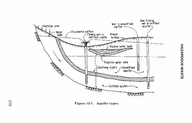
Groundwater flow is a function of precipitation, runoff,and infiltration (figure 12-1).
Groundwater flow occurs through two zones: theunsaturated (vadose or aeration) zone and the saturatedzone. Each zone can be either soil or rock. Groundwatermovement is affected by the characteristics of thematerial pore spaces (porosity) and the interconnectivityof the pore spaces (permeability). Water movementoccurs under a hydraulic gradient.
Other terms often used in groundwater are transmissivityand storativity. Both terms are bulk terms used todescribe the water over the entire hydrologic unit. Trans-missivity is directly related to permeability. Storativityis a dimensionless value often incorrectly equated withspecific yield. For a more detailed description, see theBureau of Reclamation Water Resource Technical Publi-cation, Ground Water Manual, second edition, 1995 orGroundwater, by Freeze and Cherry, 1979.
An unconfined aquifer, often referred to as a "water table"aquifer, has no overlying confining layer. Water infiltrat-ing into the ground percolates downward through air-filled interstices of the vadose zone to the saturated zone.The water table, or surface of the saturated groundwater
HA
ZA
RD
OU
S W
AS
TE
379 Figure 12-1.—Aquifer types.

FIELD MANUAL
380
body, is in contact with the atmosphere through the openpores of the material above and is in balance withatmospheric pressure.
A confined, or artesian, aquifer has an overlying,confining layer of lower permeability than the aquifer.Water in an artesian aquifer is under pressure, and whenthe confining layer is penetrated, the water will riseabove the bottom of the confining bed to an elevationcontrolled by the aquifer pressure. If the confining layertransmits some water into adjacent layers, the aquifer issaid to be a "leaky aquifer." A perched aquifer is createdby beds of clay or silt, unfractured rock, or other materialwith relatively lower permeability impeding thedownward percolation of water. An unsaturated zone ispresent between the bottom of the perching bed and theregional aquifer. Such an aquifer may be permanent ormay be seasonal.
Aquifers are typically anisotropic; i.e., flow conditionsvary with direction. In granular materials, the particleshapes, orientation, and the deposition process usuallyresult in vertical permeability being less than horizontalpermeability. The primary cause of anisotropy on amicroscopic scale is the orientation of platy minerals. Insome rock, the size, shape, orientation, and spacing ofdiscontinuities and other voids may result in anisotropy.These factors should always be considered when modelingcontaminant migration from hazardous waste sites.
After the natural flow conditions at a site are char-acterized, the presence of artificial conditions which maymodify the flow direction or velocity of groundwater isdetermined. Such items as surface water impoundmentsand drainages may influence overall groundwater flowmodels. Also, if existing water wells are present in thearea, pumping may be drawing the contaminants towardthe wells. All possible influences affecting the

HAZARDOUS WASTE
381
groundwater flow must be identified to modelcontaminant plume migration rates and paths.
Classification and Handling of Materials
Classification of soils for engineering properties isdescribed in chapter 3. “ Instructions for Logging Soilsand Surficial Deposits” (chapter 11) describes loggingprocedures, but there are two significant differences forhazardous waste investigations.
(1) Logging of the soil is often limited to visualinspection of cuttings. The sampling protocol mayprohibit the handling or poking of samples. Oftenthe samples are sealed for chemical testing, and timefor classification is restricted to the period when thesample is being packaged. Size of samples is kept toa minimum to reduce the amount of investigation-derived waste.
(2) All material recovered or generated during aninvestigation (samples, cuttings, water, etc.) shouldbe considered hazardous waste unless proven other-wise. Material removed should not be considered“normal” waste unless tested and permitted.
The RCRA “statutory” definition for hazardous waste isbroad and qualitative and does not have clear bounds.Hazardous waste is defined as material meeting theregulatory definition contained in 40 CFR 261.3.However, the definitions of solid and hazardous wastecontained in 40 CFR 261 are relevant only in identifyingthe waste. Material may still be considered solid orhazardous waste for purposes of other sections of RCRA.Some waste defined under the present regulatory statutescould become hazardous waste in the future.

FIELD MANUAL
382
From the RCRA document, the definition of hazardouswaste is any
. . .solid waste or combination of solid wasteswhich because of its quantity, concentration, orphysical, chemical, or infectious characteristicsmay: (A) cause, or significantly contribute to, anincrease in mortality or an increase in seriousirreversible, or incapacitating reversible, illness;or (B) pose a substantial present or potentialhazard to humans or the environment whenimproperly treated, stored, transported, ordisposed of, or otherwise managed.
The level of contamination acceptable within the subsur-face is based on a complex formula that involves the riskof exposure; toxicity, mobility, and volume of contami-nants; and the cost of remediation. Soil and rock removedfrom a site cannot be returned to a site after theinvestigation has been completed.
Investigation waste water must be tested and handledunder a different set of rules. If the water is mixed withcuttings, the material is considered a combination of solidwastes. If the water is discharged on a site, the watertypically must meet drinking water standards. EPA cur-rently requires that sole source aquifers have specialproject review criteria for Federal actions possiblyaffecting designated aquifers. Water withdrawn forpublic drinking water supplies currently falls under theSafe Drinking Water Act (SDWA) (Public Law 93-523)regulations, as amended and reauthorized (1974). (See40 CFR 141 G for applicable water supply systems. See40 CFR 143 for applicable water supply systems.) Notethat the number of regulated constituents and theirrespective maximum contaminant levels (MCLs) arefrequently updated.

HAZARDOUS WASTE
383
Identifying and classifying hazardous waste is describedin Hazardous Waste, by Wagner, 1990. Procedures forsite evaluation are contained in EPA Guidance forConducting Remedial Investigation and FeasibilityStudies Under CERCLA, 1988.
Field Sampling Protocol
One of the most difficult parts of any investigation iscollecting representative samples. A sampling strategymust be efficiently and logically planned which delineatessite location, number of samples collected, types ofsamples collected, testing methods to be used, and theduration and frequency of sampling. The difficulties ofdrilling in the “right” location and the problemsassociated with collecting representative samples issimilar to traditional investigations. However, forhazardous waste investigation, the COC must be con-sidered in both time and space. Statistical considera-tions should be part of the sampling program. The follow-ing are references for sampling statistical considerations:
• Harvey, R.P. “Statistical Aspects of Air SamplingStrategies.” In: Detection and Measurement ofHazardous Gases; edited by C.F. Cullis andJ.G. Firth. Heineman Educational Books, London,1981.
• Mason, B.J. Protocol for Soil Sampling: Tech-niques and Strategies. EPA EnvironmentalSystems Laboratory, Contract No. CR808529-01-2.March 30, 1982. EPA-600/54-83-0020.
• Smith, R., and G.V. James. The Sampling of BulkMaterials. The Royal Society of Chemistry,London. 1981.

FIELD MANUAL
384
• Environmental Protection Agency. Handbook forSampling and Sample Preservation of Water andWastewater. September 1982. EPA 600/4-82-029.
Sampling Strategies
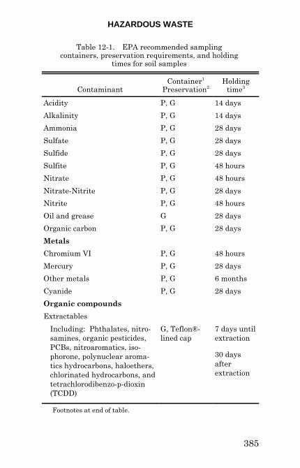
Investigators must determine the correct number andtypes of samples to be collected, the proper chemicaltesting methods (analytical procedures), and the propersampling equipment before field activities begin. Samplecontainers, preservatives, sample quantities, and properholding times are also dictated by the chosen methods.
Table 12-1 is a list of recommended sampling containersand holding times for various classes of contaminants insoils.
Several sampling strategies are available, each withadvantages and disadvantages. Random sampling usesthe theory of random chance probabilities to choose repre-sentative sample locations. This is appropriate whenlittle information exists concerning the material, loca-tions, etc. Random sampling is most effective when thenumber of sampling locations is large enough to lendstatistical validity to the random selection.
Systematic random sampling involves the collection ofrandomly selected samples at predetermined, regularintervals (i.e., a grid). The method is a common samplingscheme, but care must be exercised to avoid over-sampling of one material or population type over others.
Stratified sampling is useful if data are available fromprevious investigations and/or the investigator hasexperience with similar situations. This scheme reducesthe number of samples needed to attain a specifiedprecision. Stratified sampling involves the division of the
HAZARDOUS WASTE
385
Table 12-1.—EPA recommended sampling containers, preservation requirements, and holding
times for soil samples
ContaminantContainer1
Preservation2Holding
time3
Acidity P, G 14 days
Alkalinity P, G 14 days
Ammonia P, G 28 days
Sulfate P, G 28 days
Sulfide P, G 28 days
Sulfite P, G 48 hours
Nitrate P, G 48 hours
Nitrate-Nitrite P, G 28 days
Nitrite P, G 48 hours
Oil and grease G 28 days
Organic carbon P, G 28 days
Metals
Chromium VI P, G 48 hours
Mercury P, G 28 days
Other metals P, G 6 months
Cyanide P, G 28 days
Organic compounds
Extractables
Including: Phthalates, nitro-samines, organic pesticides,PCBs, nitroaromatics, iso-phorone, polynuclear aroma-tics hydrocarbons, haloethers,chlorinated hydrocarbons, andtetrachlorodibenzo-p-dioxin(TCDD)
G, Teflon®-lined cap
7 days untilextraction
30 daysafterextraction
Footnotes at end of table.

FIELD MANUAL
386
Table 12-1.—EPA recommended sampling containers, preservation requirements, and holding times for soil samples (continued)
ContaminantContainer1
Preservation2Holding
time3
Purgeables
Halocarbons andaromatics
G, Teflon®-linedseptum
14 days
Acrolein and acrylonitrate G, Teflon®-linedseptum
3 days
Orthophosphate P, G 48 hours
Pesticides G, Teflon®-linedcap
7 days untilextraction
30 days afterextraction
Phenols G 28 days
Phosphorus G 48 hours
Phosphorus, total P, G 28 days
Chlorinated organiccompounds
G, Teflon®-linedcap
7 days
1 P = polyethylene, G = glass. 2 All samples are cooled to 4 EC. Preservation is performedimmediately upon collection. For composites, each aliquot preservedat collection. When impossible to preserve each aliquot, samples maybe preserved by maintaining 4 EC until compositing and samplesplitting is completed. 3 Samples are analyzed as soon as possible. Times listed aremaximum holding if analysis is to be valid.
Source: Description and Sampling of Contaminated Soils,EPA/625/11-91/002 (1991).

HAZARDOUS WASTE
387
sample population into groups based on sample char-acteristics. The procedure involves handling each groupor division separately with a simple random samplingscheme.
Judgement sampling introduces a certain amount ofjudgment into the sampling approach and should beavoided if a true random sample is desired. Judgmentsampling allows investigator bias to influence decisions,which can lead to poor quality data or improper conclu-sions. If the local geology is fairly well understood,judgement sampling may provide the most efficient andcost-effective sampling scheme; however, regulatoryconcurrence, rationale, and proper documentation will benecessary.
Hybrid sampling is a combination of the types previouslydescribed. For example, an initial investigation of drumsmight be based on preliminary information concerningcontents (judgement, stratified) and then random sam-pling of the drums within specific population groups(random). Hybrid schemes are usually the method ofchoice for sampling a diverse population, reducing thevariance, and improving precision within each subgroup.
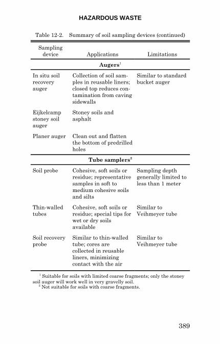
After the appropriate sampling scheme has been chosen,the specific type of samples necessary for characterizationmust be identified. The unique characteristics of the siteCOCs will play an important role in determining whichmedia will be sampled. Some sampling devices aredescribed in this manual or the Earth Manual, parts 1and 2, USBR, 1990 and 1999. A summary of samplingdevices is shown in table 12-2.

FIELD MANUAL
388
Table 12-2.—Summary of soil sampling devices
Samplingdevice Applications Limitations
Hand-held samplers
Spoons andscoops
Surface soil samplesor the sides of pits ortrenches
Limited to relativelyshallow depths;disturbed samples
Shovels andpicks
A wide variety of soilconditions
Limited to relativelyshallow depths
Augers1
Screw auger Cohesive, soft, or hardsoils or residue
Will not retain dry,cohesionless, orgranular material
Standardbucket auger
General soil orresidue
May not retain dry,cohesionless, orgranular material
Sand bucketauger
Bit designed to retaindry, cohesionless, orgranular material(silt, sand, and gravel)
Difficult to advanceboring in cohesivesoils
Mud bucketauger
Bit and bucket de-signed for wet silt andclay soil or residue
Will not retain dry,cohesionless, orgranular material
Dutch auger Designed specificallyfor wet, fibrous, orrooted soils (marshes)
1 Suitable for soils with limited coarse fragments; only thestoney soil auger will work well in very gravelly soil.
HAZARDOUS WASTE
389
Table 12-2.—Summary of soil sampling devices (continued)
Samplingdevice Applications Limitations
Augers1
In situ soilrecoveryauger
Collection of soil sam-ples in reusable liners;closed top reduces con-tamination from cavingsidewalls
Similar to standardbucket auger
Eijkelcampstoney soilauger
Stoney soils andasphalt
Planer auger Clean out and flattenthe bottom of predrilledholes
Tube samplers2
Soil probe Cohesive, soft soils orresidue; representativesamples in soft tomedium cohesive soilsand silts
Sampling depthgenerally limited toless than 1 meter
Thin-walledtubes
Cohesive, soft soils orresidue; special tips forwet or dry soilsavailable
Similar toVeihmeyer tube
Soil recoveryprobe
Similar to thin-walledtube; cores arecollected in reusableliners, minimizingcontact with the air
Similar toVeihmeyer tube
1 Suitable for soils with limited coarse fragments; only the stoneysoil auger will work well in very gravelly soil. 2 Not suitable for soils with coarse fragments.

FIELD MANUAL
390
Table 12-2.—Summary of soil sampling devices (continued)
Samplingdevice Applications Limitations
Tube samplers1 (continued)
Veihmeyertube
Cohesive soils orresidue to depth of10 feet (3 meters [m])
Difficult to drive intodense or hard mate-rial; will not retaindry, cohesionless, orgranular material;may be difficult topull from ground
Peat sampler Wet, fibrous, organicsoils
Power-driven samplers
Split spoonsampler
Disturbed samplesfrom cohesive soils
Ineffective in cohe-sionless sands; notsuitable for collectionof samples forlaboratory testsrequiringundisturbed soil
Thin-walled samplers
Fixed pistonsampler
Undisturbed samplesin cohesive soils, silt,and sand above orbelow water table
Ineffective incohesionless sands
Hydraulicpistonsampler(Osterberg)
Similar to fixed-pistonsampler
Not possible to limitthe length of push orto determine amountof partial samplerpenetration duringpush
1 Not suitable for soils with coarse fragments.

HAZARDOUS WASTE
391
Table 12-2.—Summary of soil sampling devices (continued)
Samplingdevice Applications Limitations
Thin-walled samplers (continued)
Free pistonsampler
Similar to stationarypiston sampler
Not suitable forcohesionless soils
Open drivesampler
Similar to stationarypiston sampler
Not suitable forcohesionless soils
Pitchersampler
Undisturbed samplesin hard, brittle, cohe-sive soils and ce-mented sands; repre-sentative samples insoft to medium cohe-sive soils, silts, andsome sands; variablesuccess with cohe-sionless soils
Frequentlyineffective incohesionless soils
Denisonsampler
Undisturbed samplesin stiff to hard cohe-sive soils, cementedsands, and soft rocks;variable success withcohesionless materials
Not suitable forundisturbedsampling of cohesionless soils orsoft cohesive soils
Vicksburgsampler
Similar to Denisonsampler except takeswider diametersamples
In addition, the following references may be consulted forsample collection methods:
• Environmental Protection Agency. Characterizationof Hazardous Waste Sites - A Methods Manual,Volume I - Site Investigations. April 1985. EPA600/4-84-075.

FIELD MANUAL
392
• Environmental Protection Agency. Characterizationof Hazardous Waste Sites - A Methods Manual:Volume II. Available Sampling Methods. September1983. EPA 600/4-83-040, PB84-126929.
• Environmental Protection Agency. A Compendium ofSuperfund Field Operation Methods. December 1987.EPA 540/P-87-001, PB88-181557.
Samples can be either grab or composite samples. Grabsamples are collected at a discrete point, representing onelocation and/or time interval. Composite samples arecollected from several sources which are then accumu-lated to represent a broader area of interest. Therequirements for testing will often dictate which samplingmethod is used. For example, composite samples of soilcannot be used for volatile compounds because portions ofthe contaminants may easily volatilize during collection.
Many soil samples are collected as grab samples. Soilsamples should be collected from areas where dumping,spills, or leaks are apparent. Soil samples should becollected from areas upstream and downstream fromsuspected contaminant entry and in areas wheresediment deposition is significant. Samples can becollected readily from the first 18 inches (450 mm)(depending upon the soil type) by using relatively simpletools, such as spades, scoops, and dredge scoops. If scoopsare used for collecting surface soil samples, purchaseenough scoops to use a new scoop for each sample ratherthan decontaminating scoops between samples. Not onlyis time saved, but cross contamination is kept to aminimum. The COC must also be considered. Ifsampling for heavy metals, metal scoops should not beused, or if sampling for semivolatiles, plastic scoopsshould be avoided. Samples from greater depths usuallyrequire more elaborate methods or equipment, such astest pits, hand augers, thin-wall tube samplers, hand or

HAZARDOUS WASTE
393
power corers, bucket augers, cutting or wash samples,direct-push tools, etc. The nature of the geologic materialto be sampled will influence significantly the methods touse, but every effort should be made to reduce the amountof investigation-derived waste generated from thesampling method. Direct-push sampling (such as theGeoprobe®) is preferable in that drill cuttings and drillingfluids are not generated.
A useful field pocket guide is available from EPA:Description and Sampling of Contaminated Soils,EPA/625/12-9/002, November 1991. This guide addressessoil characterization, description, sampling, and samplehandling. Within this guide are general protocols for soilsample handling and preparation. The following areprocedures from the guide:
Soil Sample Collection Procedures for Volatiles.—
1. Tube samples are preferred when collecting forvolatiles. Augers should be used only if soil condi-tions make collection of undisturbed coresimpossible. Soil recovery probes and augers withdedicated or reusable liners will minimize contactof the sample with the atmosphere.
2. Place the first adequate grab sample, maintainingand handling the sample in as undisturbed a stateas possible, in 40-milliliter (mL) septum vials or ina 1-liter (L) glass wide mouth bottle with aTeflon®-lined cap. Do not mix or sieve soilsamples.
3. Ensure the 40-mL containers are filled to the top tominimize volatile loss. Secure the cap tightly, butdo not overtighten.

FIELD MANUAL
394
4. Examine the hole from which the sample wastaken with an organic vapor instrument after eachsample increment. Record instrument readings.
5. Label and tag sample containers, and recordappropriate data on soil sample data sheets (depth,location, etc.).
6. Place glass sample containers in sealable plasticbags, if required, and place containers in icedshipping container. Samples should be cooled to4 degrees Centigrade (EC) as soon as possible.
7. Complete chain of custody forms and ship as soonas possible to minimize sample holding time.Scheduled arrival time at the analytical laboratoryshould give as much holding time as possible forscheduling of sample analyses.
8. Follow required decontamination and disposalprocedures.
Soil Sample Collection and Mixing Procedures forSemivolatiles and Metals.—
1. Collect samples.
2. If required, composite the grab samples or usediscrete grab samples.
3. If possible, screen the soils in the field through aprecleaned O-mesh (No. 10, 2-millimeter [mm])stainless steel screen for semivolatiles, or Teflon®-lined screen for metals.
4. Mix the sample in a stainless steel, aluminum (notsuitable when testing for aluminum), or glassmixing container using appropriate tool (stainlesssteel spoon, trowel, or pestle).

HAZARDOUS WASTE
395
5. After thorough mixing, place the sample in themiddle of a relatively inexpensive 1-meter (m)square piece of suitable plastic, canvas, or rubbersheeting.
6. Roll the sample backward and forward on thesheet while alternately lifting and releasingopposite sides or corners of the sheet.
7. After thorough mixing, spread the soil out evenlyon the sheet with a stainless steel spoon, trowel,spatula, or large knife.
8. Take sample container and check that a Teflon®liner is present in the cap, if required.
9. Divide the sample into quarters, and take samplesfrom each quarter in a consecutive manner untilappropriate sampling volume is collected for eachrequired container. Separate sample containerswould be required for semivolatiles, metals,duplicate samples, triplicate samples (split), andspiked samples.
10. Secure the cap tightly. The chemical preservationof solids is generally not recommended.
11. Label and tag sample containers, and recordappropriate data on soil sample data sheets (depth,location, etc.).
12. Place glass sample containers in sealable plasticbags, if required, and place containers in icedshipping container. Samples should be cooled to4 EC as soon as possible.
13. Complete chain of custody forms and ship as soonas possible to minimize sample holding time.Scheduled arrival time at the analytical laboratory

FIELD MANUAL
396
should give as much holding time as possible for scheduling of sample analyses.
14. Follow required decontamination and disposalprocedures.
Water Quality Sample Collection Methods
Surface Water Collection.—Surface water on oradjacent to a suspected hazardous waste site can yieldsignificant information with minimal sampling effort.Surface water can reveal the presence of contaminationfrom several pathway mechanisms. If only a knowledgeof the presence or absence of contamination in the wateris needed, the collection of grab samples will usuallysuffice. If the water source is a stream, samples alsoshould be collected upstream and downstream from thearea of concern. Additional monitoring of surface wateris required of seeps, spills, surface leachates, etc. If thesite has National Pollutant Discharge EliminationSystem (NPDES) outfalls, the discharges should besampled.
Water quality samples are often the most importantmaterial collected at a site. Determining the appropriatenumber of samples and appropriate test method is criticalto a successful program. A good guidance document todevelop a water quality sampling program and providethe reasoning for collecting appropriate water samples isEPA’s Handbook, Ground Water, volumes I and II,EPA/625/6-90/016. There are several factors to considerin the selection of appropriate sampling devices. Timeand money are obvious factors; however, the data use,formation permeability, water depth, and contaminationtype are considerations. Water monitoring goals andobjectives should be addressed, such as:

HAZARDOUS WASTE
397
• Is the investigation to determine source(s)?
• Are the investigations included for a time criticalremoval action?
• Have the potential contaminants been identified?
• Will there be a follow up risk assessment and/orremediation?
• Are there potential responsible parties (PRPs)involved?
Water samples can be routinely analyzed for current EPAlisted priority pollutants. Alkalinity, acidity, totalorganic halogens, and chemical oxygen demand are oftenindicators of contamination. Routine tests can be used asscreening techniques before implementing more costlypriority pollutant analyses. Bioassessment samples, ifneeded, are described in Rapid Bioassessment Protocolsfor Use in Streams and Rivers, EPA/444/4-89-001. Iftechnical impracticability (Guidance for Evaluating theTechnical Impracticability, EPA Directive 9234.2-25, ornatural attenuation are potential remediation options,additional water quality parameters may need testingconsideration.
G r o u n d w a t e r C o l l e c t i o n . — G r o u n d w a t e rcontamination is usually difficult and costly to assess,control, and remove. Monitoring wells sample a smallpart of an aquifer, depending on screen size, length,placement depth, pumping rates, and other factors. Theuse of wells and piezometers can introduce additionalproblems due to material contamination, inadequateconstruction, and uncertainties of the water zonesampled. Guarding against cross contamination ofmultiple aquifers is important. Proper well constructionrequires significant skill. General guidelines for designand construction of monitoring wells can be found inAmerican Society for Testing Materials (ASTM)

FIELD MANUAL
398
D5092-90, and guidelines for sampling can be found inRCRA Groundwater Monitoring Draft TechnicalGuidance, EPA/530-R-93-001. For general details ongroundwater quality monitoring well construction, seefigure 12-2. The location of the screen and designing anddevelopment of the screen and sand pack is extremelyimportant in hazardous waste wells. Meeting theturbidity requirement of less than five nephelometricturbidity units (NTUs) is difficult to achieve in the bestcircumstances. Drilling exploration and monitoring wellsin sequence from least to most contaminated areas isgood practice because this minimizes the possibility ofintroducing contaminants into cleaner aquifers or areas.
Although the Compendium of ERT GroundwaterSampling Procedures, EPA/540/P-91/007, providesstandard operating procedures for emergency responseteams, the recommended water quality samplingprocedures for groundwater should be in accordance withEPA’s Low-Flow (Minimal Drawdown) Ground-WaterSampling Procedures, EPA/540/S-95/504. The MinimalDrawdown (MD) method requires using a submersiblepump placed within a riser and not operated until thewell has stabilized. The use of bailers and hand pumps,including automated hand pump systems for waterquality sampling, is discouraged under the MD method.
Limiting water column disturbance is a primary reasonfor installing a dedicated submersible pump. Lowering atemporary sampling device into the water column createsa mini-slug test. The surge of water may induce sedi-ments into the monitoring well. As a result, the watermay not meet the five NTU limit that is part of therequirement for water quality monitoring wells.Sediments can significantly impact testing. If sediment

HAZARDOUS WASTE
399
Figure 12-2.—Typical monitoring wellconstruction for water quality sampling.

FIELD MANUAL
400
content is great, additional tests, such as comparing totalversus dissolved solids, should be considered.
Some sampling devices may induce volatilization.Peristaltic pumps, bailers, or hand pumps in low-flowconditions can impact the test results for semi-volatileand volatile compounds. Peristaltic pumps may inducevolatilization if the samples are lifted from depths greaterthan about 25 feet.
The MD method is the preferred sampling collectionmethod because the method uses a low pumping rate (aslow as 0.1 liter per minute) and attempts to limitdrawdown to less than 0.3 foot. If the extraction rateexceeds the ability of the formation to yield water for lowpermeability wells, turbulent conditions can be inducedwithin the borehole. Water may trickle and fall down thecasing. This may potentially increase air exposure andcan entrain air in the water.
Although preferred water quality sampling uses theMD method, other methods may be acceptable to EPA orother regulatory agencies. Devices such as bailers orperistaltic and hand pumps are routinely used at somesites. However, if these devices are used and surge thewell, water sampling protocols often require that the wellbe purged of at least three well volumes of water prior tocollecting a sample.
Whatever sample device is selected, stabilization oftypical water quality parameters, such as pH, redoxpotential, conductivity, dissolved oxygen, and turbidity,are usually required. Which water quality parametersare specified may be dependent on the site conditions andregulatory requirements. The water extraction devicesand procedures should be specified in the FSP and

HAZARDOUS WASTE
401
correlated to match the site conditions, contaminants,and the regulatory agency requirements.
Vadose Zone.—In addition to sampling aquifers athazardous waste sites, significant information can beobtained by vadose zone sampling. Leachates from COCsmigrate through the vadose zone toward the water table.Samples collected from this zone can indicate the types ofcontaminants present and can aid in assessing thepotential threat to the aquifer below. The various typesof vadose zone monitors can be used to collect watersamples or interstitial pore space vapors for chemicalanalyses and to determine directional flow of COCs. Themain advantage is that such sampling is relativelyinexpensive, simple to do, and can begin supplyinginformation before aquifer monitoring is started. Thetypes of vadose zone monitors, their applications, andtheir use in satisfying the requirements of RCRA arediscussed in Vadose Zone Monitoring at Hazardous WasteSites, EMSL-LV KT-82-018R, April 1983.
Geophysical Methods
Geophysical methods can be used effectively at hazardouswaste sites to assist in defining the subsurface characterof the site, to assist in the proper placement of monitoringwells, to identify buried containers and debris, and todecrease the safety risks associated with drilling intounknown buried materials. A good overview of thesubject of geophysical methods for surveying hazardouswaste sites is: Geophysical Techniques for Sensing BuriedWastes and Waste Migration, prepared for EPA byTechnos, Inc., available from the National Water WellAssociation.
FIELD MANUAL
402
Miscellaneous Methods
Ambient concentrations of volatile and semivolatileorganics, trace metals, and particulate matter in the aircan provide important data on the atmospheric migrationpath and the populations at risk and can be used forsource evaluations and personnel monitoring. Portablemonitoring devices such as organic vapor analyzers, staindetector tubes, or other monitors can detect the presenceof various atmospheric hazards. Other monitorscommonly used at hazardous waste sites are explosi-meters, oxygen indicators, and personal sampling pumps.
Other specialized sampling techniques may be necessaryat hazardous waste sites to sample media normally notfound in the geologic environment. Wipe samples may beused to document the presence of toxic materials and todetermine that site or equipment decontamination hasbeen adequate. Wipe sampling consists of rubbing amoistened filter paper, such as Whatman 541 filter paper,over a measured area of 15 in2 (100 cm2) to 10 ft2 (1 m2).The paper is then sent to a laboratory for analysis.
Sample Analysis
Onsite laboratories and field analytical equipment, suchas portable gas chromatographs (GCs) and immunoassaykits, can be very beneficial for rapid analyses. Rapid-analysis equipment, such as GCs, immunoassay, andcolorometric kits, are a cost-effective alternative forproviding qualitative and semi-quantitative chemicaldata and for screening large numbers of samples prior tosubmittals for laboratory testing. Another beneficial useof field screening techniques is to provide generalcontaminant level data for samples to be tested in thelaboratory. If a sample has a very high contaminant
HAZARDOUS WASTE
403
concentration, the sample may have to be diluted beforebeing analyzed to protect the laboratory instruments fromcostly contaminant saturation problems.
There are many standardized testing procedures andmethods for hazardous waste evaluation. Table 12-3 listssome common method series. Each series containsnumerous individual methods. There are over 25 series-500 (determination of organic compounds in drinkingwater) methods. Method 502.1 is for halogenated volatileorganics (purgeable halocarbons) by GC (48 compounds);Method 502.2 is for nonhalogenated volatile organics byGC (6 compounds); Method 503.1 is for aromatic andunsaturated volatile organics (purgeable aromatics) byGC (28 compounds); Method 507 is for nitrogen andphosphorus containing pesticides by GC (66 substances).
The following references discuss some of the commonmethods:
• Methods for the Determination of OrganicCompounds in Drinking Water. EPA-600/4-88/039, December 1988 (500 Series).
• Guidelines Establishing Test Procedures for theAnalysis of Pollutants Under the Clean Water Act.40 CFR Part 136, October 26, 1984 (600 Series,for effluent - wastewater discharged to a sewer orbody of water).
• Test Methods for Evaluating Solid Waste.SW-846, 2nd Edition, Revised, 1985 (8000 Seriesfor groundwater, soil, liquid, and solid wastes).
• Methods for Chemical Analysis of Water andWastes. EPA-600/4-79-020, March 1983.

FIELD MANUAL
404
Table 12-3.—Common laboratory testing methods1
Method testing series Analytes
100 - EPA method Physical properties - water
200 - EPA method Metals - water
300 - EPA method Inorganic, non-metallics - water (i.e.,alkalinity)
400 - EPA method Organics - water (i.e., chemical oxygendemand, total recoverable petroleumhydrocarbons [TRPH])
500 - EPA method Organic compounds in drinking water
600 - EPA method Organic compounds in effluent
900 - EPA method Biologic - water (i.e., coliform, fecalstreptococcal)
1000 - SW-846 method Ignitability, toxicity characteristic leachingprocedure (TCLP), extractions, cleanup,headspace - solids
3000 - SW-846 method Acid digestion, extractions, cleanup,headspace - solids
4010 - SW-846 method Screening for pentachlorophenol byimmunoassay - solids
5000 - SW-846 method Organic (purge and trap, gaschromatograph/mass spectrometer[GC/MS], sorbent cartridges)
6000 - SW-846 method Inductively coupled plasma (spectrometry)
7000 - SW-846 method Metals - solid waste
8000 - SW-846 method Organic compounds in solid waste
9000 - SW-846 method Inorganics, coliform, oil and greaseextractions - solids
1 This list is not inclusive. Significant overlap and exceptions are present. Methods listed are basic guides to provide the investigator with the generalstructure of the testing method scheme. Numerous individual methods existwithin each series.

HAZARDOUS WASTE
405
• Standard Methods for the Examination of Waterand Wastewater, 19th edition, Greenberg;American Public Health Association, Washington,DC, 1995.
Reference guides are also available from several sources,such as the Trace Analysis Laboratory Reference Guidesfrom Trace Analysis Laboratory, Inc., 3423 InvestmentBoulevard, No. 8, Hayward, California 94545, telephone(415) 783-6960.
An important consideration in planning any fieldinvestigation program is scheduling the anticipatedactivities. Sufficient time must be allowed for thepeculiarities of hazardous waste work. Several factorsmust be considered: (1) time for establishing work zonesand erecting physical barriers, (2) time for establishingequipment, personnel, and vehicle decontaminationstations, (3) time needed to decontaminate equipmentand personnel, ( 4) loss of worker efficiency due to safetymonitoring, safety meetings, and the use of protectiveclothing, (5) documentation requirements and sample-handling procedures, and (6) inventory and procurementof specialized sample containers, preservative pre-paration, and reference standards, and equipmentcalibrations.
Safety at Hazardous Waste Sites
A major factor during hazardous waste site investigationsis the safety of both the general public and the siteinvestigators. The following references may be ofassistance:

FIELD MANUAL
406
• Interim Standard Operation Safety Guides.Revised September 1982, U.S. EPA, Office ofEmergency and Remedial Response (OERR).
• Guidance Manual for Protection of Health andSafety at Uncontrolled Hazardous SubstancesSites. EPA, Center for Environmental ResearchInformation (ORD) (in draft, January 1983).
• Reclamation Safety and Health Standards.U.S. Department of the Interior, Bureau ofReclamation, Denver, Colorado, 1993.
• Chemical Substance Hazard Assessment andProtection Guide. OWENS/URIE Enterprises,Inc., Henehan, Urie, & Farlern, Wheat Ridge,Colorado, 1994.
Sample Quality Assurance and Quality Control
Sample QA procedures confirm the quality of the data bydocumenting that integrity is present throughout thesample history. Several sample types are used. Fieldblanks are samples of a "pure" substance, either water,solid, or air, which are collected in the field using thesame procedures as are used for actual environmentalsamples. The purpose of the field blank is to ensure thatoutside influences are not contaminating the truesamples (i.e., vehicular exhaust) during sampling. If"hits" are discovered in the field blank, the questionarises whether contamination not associated with the siteis affecting the true samples.
Trip blanks are samples of a "pure" substance (analyte-free deionized water which accompanies samples withvolatile contaminants) prepared in a laboratory or other

HAZARDOUS WASTE
407
controlled area and placed in a shipping container withenvironmental samples. The purpose of the trip blank isto ensure that samples were not cross contaminatedduring shipment and storage. "Hits" in a trip blankindicate that COCs were present in a container to adegree sufficient to infiltrate into the trip blank samplejar and, hence, possibly into true samples.
Equipment blanks are used when sampling equipment iscleaned and re-used for subsequent sample collection.The blanks verify the effectiveness of field cleaningprocedures. The final rinse for the sampling equipmentis often made with analyte-free deionized water. Therinse water is run on or through the sampling equipment,collected in appropriate containers and preserved. Thesesamples are usually collected on a schedule, such as onceevery 10 episodes.
Duplicates are samples collected at the same time, in thesame way, and contained, preserved, and transported inthe same manner as a corresponding duplicate.Duplicates are used to determine the precision of thelaboratory method and integrity of the sample fromcollection through testing. Duplicates are typicallycollected once every 10 samples.
Matrix spikes provide the best overall assessment ofaccuracy for the entire measurement system. For waterinvestigation episodes, a laboratory usually prepares thespike samples, sends them to the site, and the spikesample(s) are included in the sample handling andshipping process. The samples are analyzed blind by theoff-site laboratory. Matrix spikes can also be made fromcertified mixtures of a contaminant and clean soil in thefield.

FIELD MANUAL
408
All types of blanks and duplicates must be prepared inthe same sample containers as actual samples includinglabeling and identification schemes so that the laboratoryanalyzes the sample without knowing that the samplesare quality control (QC) samples (blind testing).
In addition to field QC samples, the analytical laboratoryalso uses QC samples. Method blanks are organic-free ordeionized water carried through the analytical schemelike a sample. Method blanks measure contaminationassociated with laboratory activities. Calibration blanksare prepared with standards to create a calibration curve.Internal standards are measured amounts of certaincompounds added after preparation or extraction of asample. Surrogates are measured amounts of certaincompounds added before preparation or extraction of asample to determine systematic extraction problems.Duplicates and duplicate spikes are aliquots of samplessubjected to the same preparation and analytical schemeas the original sample. Laboratory control standards(LCSs) are aliquots of organic-free or deionized water towhich known amounts of analyte have been added. LCSsare subjected to the sample preparation or extractionprocedure and analyzed as samples.
Field, laboratory, data validation, and report presentationdocuments must be meticulously maintained duringhazardous waste site investigations. All field activitiesshould be recorded in bound, consecutively numbered logbooks. Each entry should be made with indelible ink, andall strike outs should be made by a single line whichallows the original error to be legible and initialed anddated by the person making the correction. Entriesshould include date, weather conditions, personnelinvolved with the activity, the type of activity beingperformed, unusual circumstances or variations made tothe SOPs, and data appropriate to the activity being

HAZARDOUS WASTE
409
performed. This is a diary of all activities on a site. Theinvestigator responsible for the activity is responsible formaintaining the field log book. An important purpose ofthe field log book is to document any changes made toSOPs. If such changes may affect data quality,concurrence with managers or regulatory personnel isrequired in writing. All records must be under control atall times. Unique project numbers should be assigned toall log books, documents, and reports. All records mustbe maintained and custody documented so thatunauthorized changes or tampering are eliminated. Logbook entries should be photocopied on a regular scheduleto ensure that field data are not lost if the original bookis lost or destroyed.
Activities during an investigation must be reviewed toensure that all procedures are followed. System auditsshould consist of inspections of training status, records,QC data, calibrations, and conformance to SOPs. Systemaudits are performed periodically on field, laboratory, andoffice operations. Each major investigation type shouldbe subject to at least one system audit as early aspracticable. Performance audits include evaluation andanalysis of check samples, usually from laboratoryactivities. Readiness reviews occur immediately prior tobeginning each type of field activity to assess thereadiness of the team to begin work. A checklist ofprerequisite issues, such as necessary equipment,controlled documents, training, assignments, spare parts,field arrangements, etc., are discussed and documented.
If any weaknesses or deficiencies are identified, theinvestigator must resolve them before field activitiesproceed.

FIELD MANUAL
410
Sample Management
There must be control and documentation of all samplesafter the environmental samples are collected in the field.The proper quantity of a sample must be collected to havesufficient volume for the subsequent analysis. The propersample container and preservative must be used so thatsample integrity is not compromised. Many types ofsamples (e.g., volatiles) must be cooled, usually to 4 EC,throughout their history after collection. The properanalytical methods must be identified to obtain thedesired result. The laboratory must handle and track thereceived samples in a timely and accurate manner toensure that the results are correct.
Sample Custody
Sample custody is a prime consideration in the propermanagement of samples. Sample custody is designed tocreate an accurate, written, and verified record that canbe used to trace the possession and handling of thesamples from collection through data analyses andreporting. Adequate sample custody is achieved bymeans of QA-approved field and analyticaldocumentation. A sample is considered in custody if thesample is (1) in one's actual physical possession, (2) is inone's view after being in one's physical possession, (3) isin one's physical possession and then locked up orotherwise sealed so that tampering will be evident, or(4) is kept in a secure area restricted to authorizedpersonnel only. Personnel who collect samples arepersonally responsible for the care and integrity of thesecollected samples until the samples are properlytransferred or dispatched. To document that samples areproperly transferred or dispatched, sample identification

HAZARDOUS WASTE
411
and chain of custody procedures must be followed.Sample custody in the field and in transit involves thesteps described below.
Sample Identification.—The sample must first beproperly and uniquely identified. Sample identificationentails establishing a scheme which ensures that eachsample is identified in such a way that one sample cannotbe mistaken for another. Examples of sample labels areshown in figure 12-3. Labels must be filled outimmediately after the sample is collected to ensure thatcontainers are not later misidentified. Indelible ink mustbe used on all labels, and the writing must be legible. Forsamples which require preservation, the sample labelsmust have a space on the label reserved for noting thepreservative added, or other treatments, such as filtering,compositing, etc. Labels can be removed from a samplejar during shipment, especially if the accompanying icemelts and saturates the shipping labels. Double-labelsamples such as sacked soil whenever possible orcompletely wrap the label over the sample bottle withwide, water-proof tape. Also record the collection of eachsample in the field log book and chain of custody records. Chain of Custody.—Once all samples for a specific sam-pling task have been collected, the sampler(s) will com-plete the chain of custody record (figure 12-4). Specificprocedures for completing this form should be included inthe work plan documents specific to the project. Thisrecord accompanies the samples to their destination. Allsamples typically are transferred from the sampletransport container (e.g., cooler) and kept in the exclusionzone until transferred to a noncontaminated sampletransport container in the contamination reduction zone.The samples, with accompanying documentation, are

FIELD MANUAL
412
Figure 12-3.—Soil and water sample identification labels.

HA
ZA
RD
OU
S W
AS
TE
413 Figure 12-4.—Chain of custody record.

FIELD MANUAL
414
then prepared for either distribution to the onsitelaboratory or shipment to an analytical laboratory in thesupport zone.
When transferring the possession of samples, theindividuals relinquishing and receiving the samples willsign, date, and note the time on the chain of custodyrecord. This record documents sample custody transferfrom the sampler to the analyst. Note that somecommercial shippers (such as Federal Express) do notsign chain of custody records but do prepare separateshipping documents which indicate receipt of thecooler(s). When samples are passed among fieldpersonnel while still onsite, chain of custody records donot need to be signed, as long as physical possession isretained by identified, responsible personnel duringtransit of the container(s). Packaging
Samples must be packaged properly for shipment anddispatched to the appropriate laboratory for analysis; aseparate record accompanies each shipment. Sampleswithin shipping containers will be sealed for shipment tothe laboratory by using custody seals (figure 12-5). Sealsare made of paper, with adhesive backing, so that theywill tear easily to indicate possible tampering. There aretwo methods of using custody seals. One method is toplace several sample containers in individual plastic bags(or boxes) within the shipping container and then placethe custody seal along the only opening of each bag. Anadvantage of this scheme is that the seal is not exposedto outside influences; but the disadvantages are that thebags are very pliable, and shifting may cause the seal tobreak, and the seal may become immersed in water if icemelts around the bags. The second method is to place thecustody seal on the outside of the cooler, along a seam of

HA
ZA
RD
OU
S W
AS
TE
415 Figure 12-5—Custody seal.

FIELD MANUAL
416
the lid. The advantage of this method is that the seal isstuck to the solid body of the cooler. The maindisadvantage is that the seal is exposed to handling bythe shipping company and other personnel from the fieldto the laboratory. The seal must not be broken acci-dentally because a broken seal will place all thesamples represented by the seal in jeopardy ofdisqualification due to tampering. An option may be toplace clear tape over the seal as added protection.
The samples within a container must be packed to avoidrattling and breakage. Styrofoam "popcorn" or bubblepack sheeting are acceptable packing materials. Organicpacking materials, including sawdust, should be avoideddue to the possibility of becoming wet from melting ice.Each sample jar should be wrapped such that jar-to-jarcontact is avoided. Also, it is usually desirable to placeice at the bottom of the container, and place the samplesabove the ice, with a water-proof barrier between the iceand samples. This way, if the ice melts, there is alessened probability of the samples becoming immersed.If time is available, ice should be double-wrapped, usingseveral "ice packages" to lessen spillage potential.Chemical ice packs and dry ice should be avoided, ifpossible, to lessen the chance of chemical contamination.The chain of custody record must accompany eachcontainer and list only the samples contained within thespecified cooler. The original chain of custody recordshould be sealed in a "zip-lock" plastic bag and taped tothe inside top of the cooler lid. When the laboratoryopens a cooler, the number and identification of eachsample contained within the cooler must exactly matchthe corresponding chain of custody record. A copy of thechain of custody record is to be retained by theinvestigator or site manager, and a copy is also retainedby the laboratory. A three-carbon copy type chain ofcustody record is best.
HAZARDOUS WASTE
417
The water drain at the lower edge of the cooler must besealed so there is no possibility of the drain opening. Ifany leakage occurs from a cooler containing environ-mental samples, the shipping company will cease ship-ment and delay the arrival of the samples, possiblyexceeding the holding times of the contained samples. Ashipping company may have unique requirements; but asa general rule, the weight of a cooler should not exceed50 to 70 pounds. If sent by mail, the package must bereceipt requested. If sent by common carrier, a govern-ment bill of lading can be used. Proper shipment trackingmethods must be in place. Copies of all receipts, etc.,must be retained as part of the permanentdocumentation.
Upon arrival at the laboratory, the containers will beopened, the custody seals inspected and documented, andany problems with chain of custody, temperature, orsample integrity noted. The laboratory custodian willthen sign and date the chain of custody record and enterthe sample identification numbers into a bound,paginated log book, possibly assigning and cross-referencing a unique laboratory number to each samplereceived. The laboratory then controls the samplesaccording to the SOPs specified in their work plandocuments.
Decontamination
Decontamination consists of removing contaminantsand/or changing their chemical nature to innocuoussubstances. How extensive decontamination must bedepends on a number of factors, the most important beingthe type of contaminants involved. The more harmful thecontaminant, the more extensive and thorough decon-tamination must be. Less harmful contaminants may

FIELD MANUAL
418
require less decontamination. Only general guidance canbe given on methods and techniques for decontamination.The exact procedure to use must be determined afterevaluating a number of factors specific to the site.
When planning site operations, methods should bedeveloped to prevent the contamination of people andequipment. For example, using remote sampling tech-niques, using disposable sampling equipment, wateringdown dusty areas, and not walking through areas ofobvious contamination would reduce the probability ofbecoming contaminated and require a less elaboratedecontamination procedure.
The initial decontamination plan is usually based on aworst-case situation. During the investigations, specificconditions are evaluated including: type of contaminant,the amount of contamination, the levels of protectionrequired, and the type of protective clothing needed. Theinitial decontamination system may be modified byadapting it to actual site conditions.