hawick flood protection method… · 0.1 september 2016 draft for comment jim baxter stuart slaven...
TRANSCRIPT

663475‐HP3‐CH2‐ALL‐CM‐RE‐Z‐0001
C O N S T R U C T I O N M E T H O D O L O G Y R E P O R T
Hawick Flood Protection Scheme
Prepared for
Scottish Borders Council
March 2017
CH2M HILL City Park 368 Alexandra Parade Glasgow G31 3AU
Scottish Borders Council Council Headquarters Newtown St Boswells
Melrose TD6 0SA

III
Contents Section Page
Acronyms and Abbreviations .......................................................................................................... v
Document History .......................................................................................................................... vi
Introduction ................................................................................................................................ 1‐1 1.1 Purpose ...................................................................................................................... 1‐1 1.2 Background ................................................................................................................ 1‐1
Summary of Construction Activities ............................................................................................ 2‐1
Advance works ............................................................................................................................ 3‐1 3.1 Tree Felling ................................................................................................................. 3‐1 3.2 Service Diversions ...................................................................................................... 3‐1 3.3 Traffic Management Preparatory Works ................................................................... 3‐2
Site Compounds .......................................................................................................................... 4‐1 4.1 Conclusions ................................................................................................................ 4‐7
Construction Access .................................................................................................................... 5‐8 5.1 General ....................................................................................................................... 5‐8 5.2 Work Sections Constructed from the Watercourse .................................................. 5‐9 5.3 Cofferdams ............................................................................................................... 5‐10 5.4 Raised Platforms ...................................................................................................... 5‐11 5.5 Crossing Points ......................................................................................................... 5‐12 5.6 Dewatering of excavations ...................................................................................... 5‐14
Outline Construction Methods .................................................................................................... 6‐1 6.1 General ....................................................................................................................... 6‐1
6.1.1 Site Preparation ............................................................................................ 6‐1 6.1.2 Equipment and Materials ............................................................................. 6‐2
6.2 Embankments ............................................................................................................ 6‐3 6.3 Sheet Pile Walls (top of riverbank) ............................................................................ 6‐4 6.4 Sheet Pile Walls (no riverbank) .................................................................................. 6‐5 6.5 Reinforced Concrete Cantilever Walls ....................................................................... 6‐7 6.6 Culverts ...................................................................................................................... 6‐8 6.7 Riverbank Erosion Protection .................................................................................... 6‐9 6.8 Bridge Modification ................................................................................................... 6‐9 6.9 Pumping Stations ....................................................................................................... 6‐9
Impact of Construction Sequence and Timing .............................................................................. 7‐1 7.1 Contract Constraints .................................................................................................. 7‐1 7.2 Temporary Flood Protection ...................................................................................... 7‐1
Reinstatement ............................................................................................................................ 8‐1 8.1 Residential Gardens ................................................................................................... 8‐1 8.2 Amenity Areas ............................................................................................................ 8‐1 8.3 Roads and Footpaths ................................................................................................. 8‐1 8.4 Existing Structures ..................................................................................................... 8‐1
Appendices
Appendix A Possible In‐channel Work

CONTENTS
Section Page
IV
Tables
Table 1: Summary of Work Sections Table 2: Summary of Pumping Stations Table 3: Site Compound locations to be included in Scheme Application
Figures
Figure 1: Possible Site Compounds – Common Haugh car park Figure 2: Possible Site Compounds – Former N Peal Mill site Figure 3: Possible Site Compounds – Little Haugh park Figure 4: Possible Site Compounds – Former Pringle Mill site Figure 5: Possible Site Compounds – Mansfield Gardens vacant plot Figure 6: Possible Site Compounds – Vacant plot behind National Grid site Figure 7: Possible Site Compounds Figure 8: Example of a cofferdam, White Cart Water FPS, Glasgow, 2009 Figure 9: Example of a raised platform Figure 10: Pipe bridge under construction Figure 11: Example of a Bailey bridge in use Figure 12: Schematic of Embankment Figure 13: Schematic of Sheet Pile Wall (at top of riverbank) Figure 14: Schematic of Sheet Pile Wall (with no riverbank) Figure 15: Schematic of Reinforced Concrete Cantilever Wall

V
Acronyms and Abbreviations BCR Benefit Cost Ratio
RC Reinforced Concrete
SBC Scottish Borders Council
SEPA Scottish Environment Protection Agency

VI
Document History BIM reference number: 663475‐HP3‐CH2‐ALL‐CM‐RE‐Z‐0001
This document has been issued and amended as follows:
Version Date Description Created by Verified by Approved by
0.1 September 2016 Draft for comment Jim Baxter Stuart Slaven Steven Vint
0.2 November 2016 Revision to section 6.4 bullet point 3
Jim Baxter Stuart Slaven Steven Vint
0.3 January 2017 1.1 revised to clarify contractor’s responsibility
for selecting actual construction methods.
5.3 revised to clarify likelihood of use of
cofferdams
5.6 added to clarify dewatering of excavations
Jim Baxter Stuart Slaven Steven Vint
0.4 January 2017 Table 1 updated
Section 3 updated
Section 6.7 updated
Section 7.1 updated
Section 9 added
Jim Baxter Stuart Slaven Steven Vint
0.5 February 2017 Final Updates Katie Born Stuart Slaven Steven Vint
0.6 March 2017 Table 4 updated for WS8 Jim Baxter Stuart Slaven Steven Vint
1.0 March 2017 FINAL FOR CLIENT ISSUE Jim Baxter Stuart Slaven Steven Vint
CH2M has prepared this document in accordance with the scope and instructions of Scottish Borders Council, our client, for their sole and specific use. Any other persons or organisations who use any information contained herein do so at their own risk.

SECTION 1
1‐1
Introduction
1.1 Purpose The purpose of this report is to discuss a possible outline construction methodology for Hawick Flood Protection Scheme (FPS). This has been done in the context of risk management with respect to the anticipated social and environmental impacts resulting from the construction process. It is considered necessary to discuss different possibilities at this stage such that the Project Team are comfortable that the outline design could be constructed safely and without major logistical challenge.
Notwithstanding this, it is not possible for SBC or CH2M to determine or prescribe exactly which methods of construction the contractor will select, or in which sequence they will construct the works. The contractor will be solely responsible for exercising their experience and professional judgement to construct the works in a manner which complies with the works information and all applicable laws and regulations. In doing so, the contractor may choose to use methods not considered or discussed in this report.
Following completion of the project’s outline design phase, this outline construction methodology has been carried out with a view to informing the:
Scheme application (including scheme cost estimate) under the Flood Risk Management (Scotland) Act 2009;
Environmental Impact Assessment under the Flood Risk Management (Flood Protection Schemes, Potential Vulnerable Areas and Local Plan Districts) (Scotland) Regulations 2010;
Habitat Regulations Assessment/ Appropriate Assessment under the Conservation (Natural Habitats & c.) Regulations 1994; and
CAR application under the Water Environment (Controlled Activities) (Scotland) Regulations 2011.
1.2 Background Hawick, in the Scottish Borders, has a history of flooding from the River Teviot, with notable events occurring in October 2005, November 2009, December 2015 and January 2016. The Hawick FPS is being promoted by Scottish Borders Council (SBC) under the Flood Risk Management (Scotland) Act 2009. CH2M was appointed by SBC to develop a Scheme for Hawick to reduce flood risk from the River Teviot and the backwater effects associated with it on the Slitrig Water.
Much of contemporary Hawick was established as part of the 18th century weaving industry. Mills were constructed near the rivers for a source of power, followed by roads and houses to serve the industry. As a result, many buildings and roads are immediately next to the river, which presents a number of challenges with respect to construction of the flood protection scheme.


SECTION 2
2‐1
Summary of Construction Activities The proposed scheme has been divided into thirty three work sections, based on form of construction and geographic divisions. It is anticipated that the contractor will develop their programme and sequence of construction based on the work sections. Details are as follows:
Work Section
Location Length
(m)
Maximum height above dry side ground level
(m)
Form of Construction
1 Community Hospital 220 2.3 Sheet Pile Wall
2 Common Haugh 143 1.2 Sheet Pile Wall
3 Burns Club 49 2.9 Sheet Pile Wall
4 James Thomson North Abutment
36 0.7 Abutment Modifications
5 Commercial Road 1 55 0.6 Sheet Pile Wall
6 Lovat Mill 163 2.8 Sheet Pile Wall
7 Commercial Road – up to Victoria Bridge
87 2.0 Sheet Pile Wall
8 Commercial Road – Sainsbury’s
312 2.0 Reinforced Concrete Cantilever Wall
9 Mansfield Road – Mansfield Crescent to footbridge
288 1.8 Sheet Pile Wall
10 Mansfield Road – footbridge to Mansfield Gardens
275 1.4 Sheet Pile Wall
11 Mansfield Road – National Grid Depot
180 1.3 Sheet Pile Wall
12 Mansfield Road – WwTW 300 1.8 Reinforced Concrete Cantilever Wall
13 Hawick RFC 365 2.2 Sheet Pile Wall
14 Albert Park & CRC 339 2.0 Reinforced Concrete Cantilever Wall
15 SBC Depot 250 2.0 Sheet Pile Wall
16 Volunteer Park 190 1.4 Sheet Pile Wall
17 Buccleuch Park 145 1.6 Sheet Pile Wall
18 Cricket Pavilion 43 1.8 Sheet Pile Wall
19 High School Car Park 89 2.0 Sheet Pile Wall
20 Hawick High School 210 2.5 Sheet Pile Wall
21 Royal Mail Sorting Office 118 2.1 Sheet Pile Wall
SECTION 2 – SUMMARY OF CONSTRUCTION ACTIVITIES
2‐2
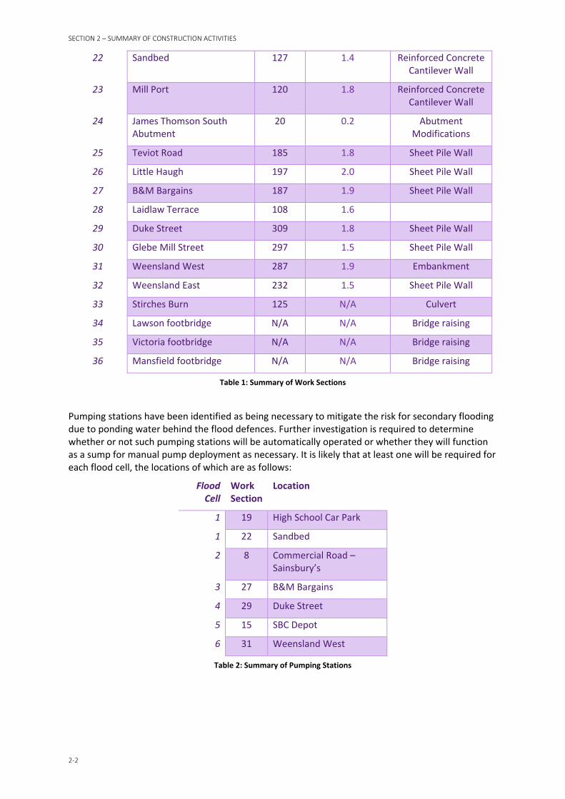
22 Sandbed 127 1.4 Reinforced Concrete Cantilever Wall
23 Mill Port 120 1.8 Reinforced Concrete Cantilever Wall
24 James Thomson South Abutment
20 0.2 Abutment Modifications
25 Teviot Road 185 1.8 Sheet Pile Wall
26 Little Haugh 197 2.0 Sheet Pile Wall
27 B&M Bargains 187 1.9 Sheet Pile Wall
28 Laidlaw Terrace 108 1.6
29 Duke Street 309 1.8 Sheet Pile Wall
30 Glebe Mill Street 297 1.5 Sheet Pile Wall
31 Weensland West 287 1.9 Embankment
32 Weensland East 232 1.5 Sheet Pile Wall
33 Stirches Burn 125 N/A Culvert
34 Lawson footbridge N/A N/A Bridge raising
35 Victoria footbridge N/A N/A Bridge raising
36 Mansfield footbridge N/A N/A Bridge raising
Table 1: Summary of Work Sections
Pumping stations have been identified as being necessary to mitigate the risk for secondary flooding due to ponding water behind the flood defences. Further investigation is required to determine whether or not such pumping stations will be automatically operated or whether they will function as a sump for manual pump deployment as necessary. It is likely that at least one will be required for each flood cell, the locations of which are as follows:
Flood Cell
Work Section
Location
1 19 High School Car Park
1 22 Sandbed
2 8 Commercial Road – Sainsbury’s
3 27 B&M Bargains
4 29 Duke Street
5 15 SBC Depot
6 31 Weensland West
Table 2: Summary of Pumping Stations
SECTION 3
3‐1
Advance works The following section covers work which may be carried out in advance of the main works contract. This may be done so as to reduce the risk of delay to the main works, provide greater certainty of cost, or reallocate activities which are more suited to specialist contractors.
It is considered unlikely that enabling works carried out in advance of the main works contract will require working within the watercourse. Where utility services cross bridges that are to be modified as part of the works, it is likely that the associated services will be diverted onto temporary cantilever structures during the main works contract.
3.1 Tree Felling The banks of the River Teviot and Slitrig Water contain many trees. Most of these are self‐seeded, and elsewhere, cultivated trees line sections of road and parkland. Both types of tree present an obstacle for construction of the flood defences, and a number of them will have to be removed in their entirety (including stumps) to enable access.
There are two possible approaches to tree felling which mitigate different risks to the project. The first approach would be to carry out tree felling in advance of the main works. This would enable trees to be felled outside the bird nesting season, therefore mitigating the risk of delay if trees identified for removal were found to contain nesting birds. However, this would likely have to be done prior to a main works contractor being appointed and might therefore result in more trees being felled than absolutely necessary, or trees being felled up to two years in advance of works taking place, which may result in adverse public reaction.
The second approach would be to make the main works contractor responsible for tree felling. This would reduce the number of trees felled to only those that the contractor actually needed to be removed, since unnecessary felling would an additional unrecoverable cost. However, the contractor’s programme would likely preclude all trees from being felled outside the bird nesting season, thereby increasing the risk of delay. The contractor might be entitled to additional payment in the event of delays which were outside their control.
Feedback from the public exhibition indicated that many local people are in favour of removing trees from the riverbanks, due to the perception that these reduce the conveyance capacity of the watercourse. Meanwhile, there was also feedback in favour of retaining the cultivated trees along Mansfield Road, Duke Street and Little Haugh Park. While some of the riverbank trees could potentially be retained, the avenue trees referred to above will certainly have to be removed to enable construction.
Further discussion is required to establish SBC’s preferred approach. If trees are to be retained for as long as possible, and the number felled to be minimized, then tree felling should be included in the contractor’s scope. This approach, however, will require an additional contract constraint to ensure the Contractor takes account of bird nesting season within their programme. Since the contract award date is estimated to be in April, during bird nesting season, this may not be a practicable approach.
3.2 Service Diversions The roads lining the riverbanks of the River Teviot contain a number of buried services (electricity, gas, telecommunications, water and waste), as well as overhead services (telecommunications, electricity and lighting). Many of these present an obstacle for construction of the flood defences, as they either clash with, or are in close proximity to the works. Each service provider will have to be consulted to determine which services can be diverted and which will have to be protected.
SECTION 3 – ADVANCE WORKS
3‐2
Experience indicates that the diversion of services is a complex and lengthy process. The process is regulated under the New Roads and Streetworks Act 1991, but there is no provision for enforcing diversions to be completed within a specific time period. If diversion works were included within the scope for the main works contract, the contractor might be entitled to additional payment in the event of delays caused by the service providers, and this is considered a likely scenario which would result in a risk of unacceptably high additional costs.
Planning and carrying out the service diversions in advance would mitigate the risk of claims from the main works contractor. Engaging a single contractor to carry out the preparatory pipe and duct laying for all the service providers would also minimise the number of occasions the road was excavated and therefore minimise the impact to the public. This approach generally worked well for the Selkirk and white Cart FPS.
It is considered preferable to carry out service diversions as advance works, with a single contractor carrying out preparatory pipe and duct laying. Such works will develop into a project in its own right and will require adequate Project Team staff to manage, co‐ordinate and supervise, along with a Principal Contractor who is suitably experienced in co‐ordinating the five separate service providers. It is likely that street lighting diversion works will be undertaken as part of the main works contract.
3.3 Traffic Management Preparatory Works It is likely that a temporary road closure will be required on the A7 Commercial Road between Victoria footbridge and North Bridge to enable the adjacent flood defence wall to be constructed. A possible diversion route was identified, which comprises directing traffic onto Wilton Path adjacent to Teviotdale Mill, then Princes Street, before rejoining the A7 at Wilton Hill north of North Bridge roundabout. A full road closure will be dependent on the required form of construction for the Commercial Road wall, which can only be fully determined once the slit trenches to prove the existing construction form are completed.
For the diversion route to work effectively it may be necessary to provide a signalized junction at the corner of Princes Street and Wilton Hill. It may also be necessary to provide additional pedestrian crossings and/or traffic management measures along Princes Street. This will be investigated further as part of a more comprehensive Traffic Management Plan.
SECTION 4
4‐1
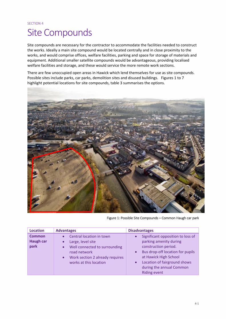
Site Compounds Site compounds are necessary for the contractor to accommodate the facilities needed to construct the works. Ideally a main site compound would be located centrally and in close proximity to the works, and would comprise offices, welfare facilities, parking and space for storage of materials and equipment. Additional smaller satellite compounds would be advantageous, providing localised welfare facilities and storage, and these would service the more remote work sections.
There are few unoccupied open areas in Hawick which lend themselves for use as site compounds. Possible sites include parks, car parks, demolition sites and disused buildings. Figures 1 to 7 highlight potential locations for site compounds, table 3 summarises the options.
Figure 1: Possible Site Compounds – Common Haugh car park
Location Advantages Disadvantages
Common Haugh car park
Central location in town
Large, level site
Well connected to surrounding road network
Work section 2 already requires works at this location
Significant opposition to loss of parking amenity during construction period.
Bus drop‐off location for pupils at Hawick High School
Location of fairground shows during the annual Common Riding event
SECTION 4 – SITE COMPOUNDS
4‐2
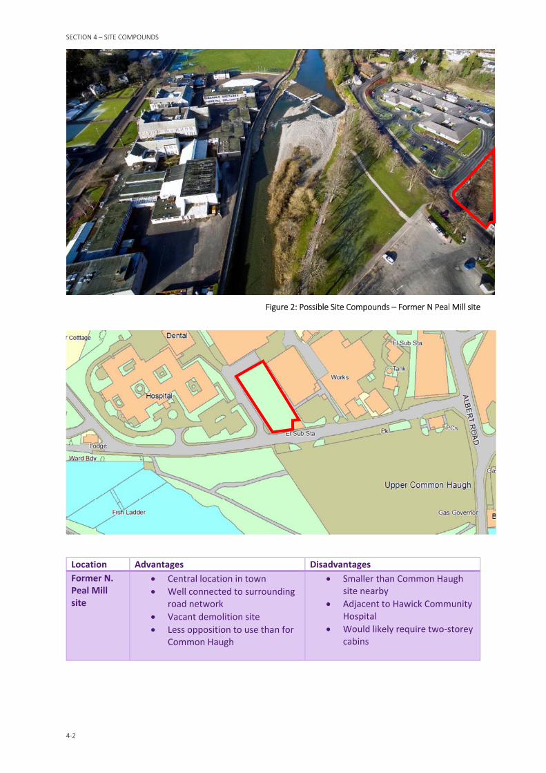
Figure 2: Possible Site Compounds – Former N Peal Mill site
Location Advantages Disadvantages
Former N. Peal Mill site
Central location in town
Well connected to surrounding road network
Vacant demolition site
Less opposition to use than for Common Haugh
Smaller than Common Haugh site nearby
Adjacent to Hawick Community Hospital
Would likely require two‐storey cabins
SECTION 4 – SITE COMPOUNDS
4‐3
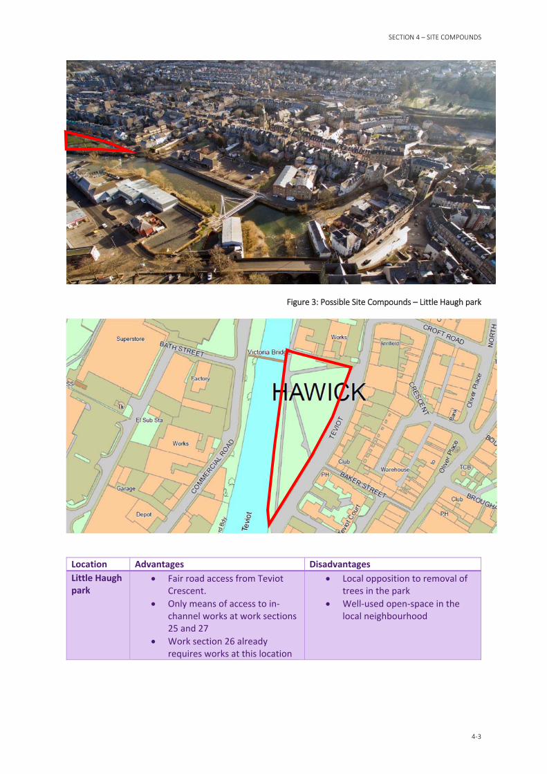
Figure 3: Possible Site Compounds – Little Haugh park
Location Advantages Disadvantages
Little Haugh park
Fair road access from Teviot Crescent.
Only means of access to in‐channel works at work sections 25 and 27
Work section 26 already requires works at this location
Local opposition to removal of trees in the park
Well‐used open‐space in the local neighbourhood
SECTION 4 – SITE COMPOUNDS
4‐4
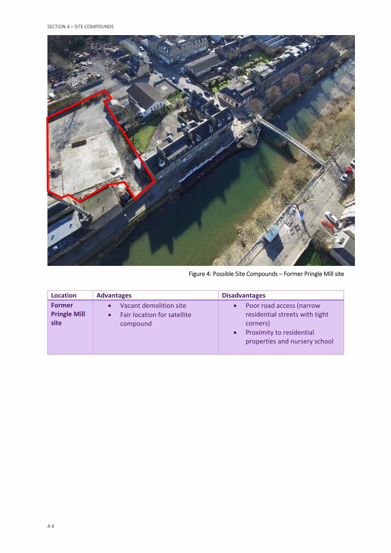
Figure 4: Possible Site Compounds – Former Pringle Mill site
Location Advantages Disadvantages
Former Pringle Mill site
Vacant demolition site
Fair location for satellite compound
Poor road access (narrow residential streets with tight corners)
Proximity to residential properties and nursery school
SECTION 4 – SITE COMPOUNDS
4‐5
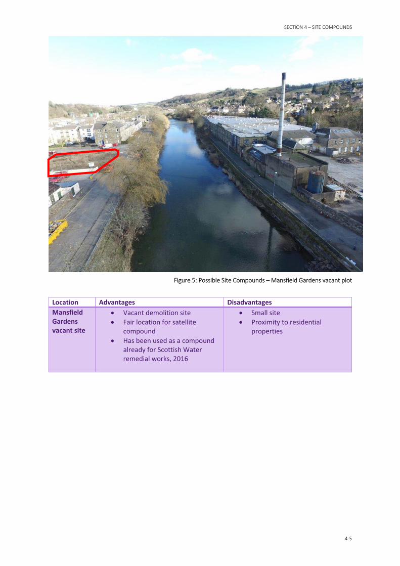
Figure 5: Possible Site Compounds – Mansfield Gardens vacant plot
Location Advantages Disadvantages
Mansfield Gardens vacant site
Vacant demolition site
Fair location for satellite compound
Has been used as a compound already for Scottish Water remedial works, 2016
Small site
Proximity to residential properties
SECTION 4 – SITE COMPOUNDS
4‐6
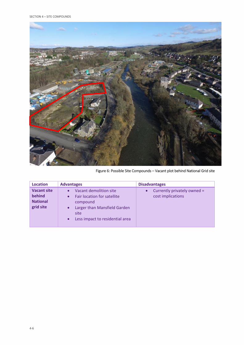
Figure 6: Possible Site Compounds – Vacant plot behind National Grid site
Location Advantages Disadvantages
Vacant site behind National grid site
Vacant demolition site
Fair location for satellite compound
Larger than Mansfield Garden site
Less impact to residential area
Currently privately owned = cost implications

SECTION 4 – SITE COMPOUNDS
4‐7
Figure 7: Possible Site Compounds
Location Advantages Disadvantages
Hamilton Road site
Good location for satellite compound
Good road access
Undeveloped site
Proximity to residential properties
Occupation of a greenfield site
4.1 Conclusions Following the discussion above, the table below indicates which sites will be included within the limit of land affected, forming part of the Scheme Application. Discussion with the relevant landowners will be required in advance of the Scheme Application to determine if these areas are feasible for use as site compounds over 30 months. Notwithstanding this, the contractor will remain at liberty to negotiate directly with third party land owners if they wish to secure the use of further sites.
Location Conclusion Comments
Common Haugh car park Discount Unacceptable opposition to use
Former N. Peal Mill site Include Vacant site in central location
Little Haugh park Include Key location for accessing in‐channel works
Former Pringle Mill site Discount Poor access / H&S concerns
Mansfield Gardens vacant site Discount Limited use due to size
Vacant site behind National Grid site
Include Vacant site in good location for left bank remote work sections
Hamilton Road site Discount Avoid use of greenfield site
Table 3: Site Compound locations to be included in Scheme Application

SECTION 5 – CONSTRUCTION ACCESS
5‐8
Construction Access
5.1 General As described in the introduction, many of the proposed work sections are difficult to access. This is due to the proximity of buildings, roads and other infrastructure to the riverbanks. Working from within the watercourse is a possible solution but it presents a number of challenges.
Most construction equipment is unsuited to operating in water. Dry working areas are required to improve workers health and safety, protect the equipment from water damage and to protect the watercourse from pollution. This can be achieved by forming temporary cofferdams to exclude water, or raised platforms which are above the water level.
The use of such temporary working areas must be carefully planned and executed since they can affect the conveyance of the watercourse and flood risk. Narrowing the channel will result in river levels which are higher and more sensitive to low return period rainfall events. Platforms which are set too low will be frequently inundated, and those set too high will have an unacceptable impact on river levels and flood risk.
The position and extent of such working areas can also have an ecological impact. Disturbing the riverbed material during salmon spawning season is prohibited under legislation. Even when lawfully constructed outside this season, the position of working areas may affect the viability of habitats when spawning begins due to change in the normal river flow regime.
The design and implementation of temporary works, which includes construction access, will be the sole responsibility of the contractor. It will be for the contractor to propose temporary works as part of their method statements, which will then be submitted to the employer’s representative for review and acceptance. The purpose of the following sections is to discuss the advantages and disadvantages of different forms of temporary works and how these might affect the design of the flood defences and preparation of scheme documentation.
SECTION 5 – CONSTRUCTION ACCESS
5‐9
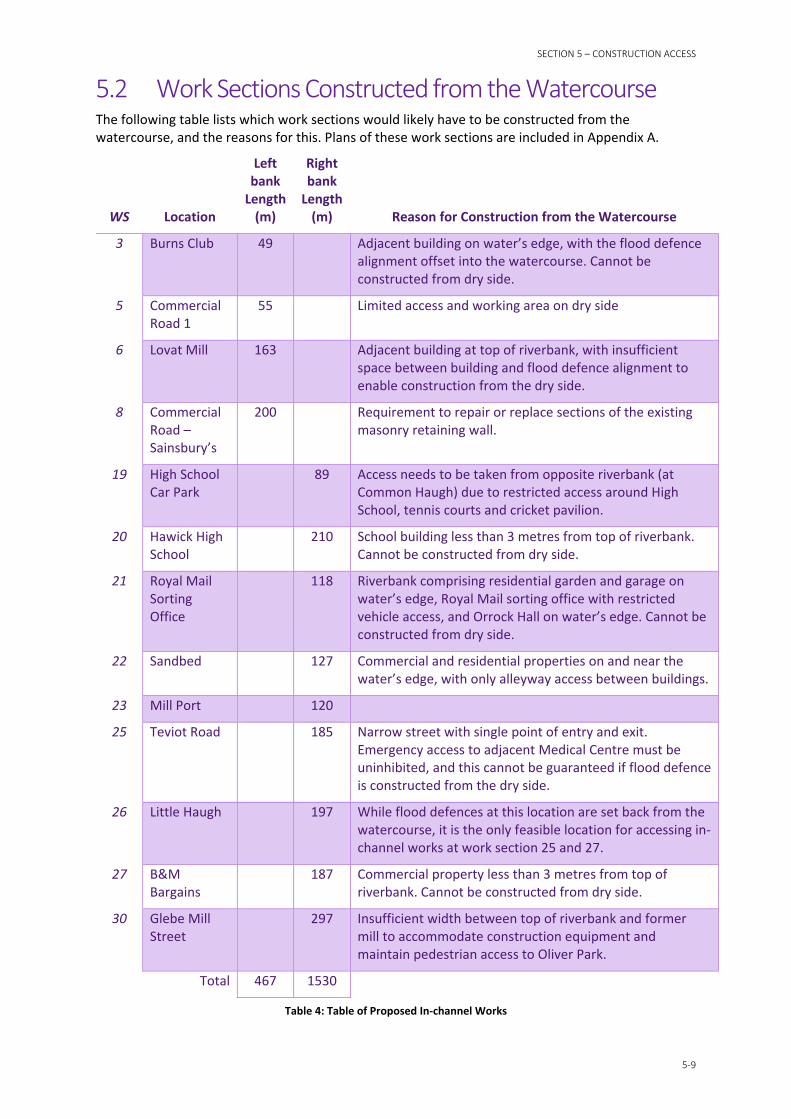
5.2 Work Sections Constructed from the Watercourse The following table lists which work sections would likely have to be constructed from the watercourse, and the reasons for this. Plans of these work sections are included in Appendix A.
WS Location
Left bank Length (m)
Right bank Length (m) Reason for Construction from the Watercourse
3 Burns Club 49 Adjacent building on water’s edge, with the flood defence alignment offset into the watercourse. Cannot be constructed from dry side.
5 Commercial Road 1
55 Limited access and working area on dry side
6 Lovat Mill 163 Adjacent building at top of riverbank, with insufficient space between building and flood defence alignment to enable construction from the dry side.
8 Commercial Road – Sainsbury’s
200 Requirement to repair or replace sections of the existing masonry retaining wall.
19 High School Car Park
89 Access needs to be taken from opposite riverbank (at Common Haugh) due to restricted access around High School, tennis courts and cricket pavilion.
20 Hawick High School
210 School building less than 3 metres from top of riverbank. Cannot be constructed from dry side.
21 Royal Mail Sorting Office
118 Riverbank comprising residential garden and garage on water’s edge, Royal Mail sorting office with restricted vehicle access, and Orrock Hall on water’s edge. Cannot be constructed from dry side.
22 Sandbed 127 Commercial and residential properties on and near the water’s edge, with only alleyway access between buildings.
23 Mill Port 120
25 Teviot Road 185 Narrow street with single point of entry and exit. Emergency access to adjacent Medical Centre must be uninhibited, and this cannot be guaranteed if flood defence is constructed from the dry side.
26 Little Haugh 197 While flood defences at this location are set back from the watercourse, it is the only feasible location for accessing in‐channel works at work section 25 and 27.
27 B&M Bargains
187 Commercial property less than 3 metres from top of riverbank. Cannot be constructed from dry side.
30 Glebe Mill Street
297 Insufficient width between top of riverbank and former mill to accommodate construction equipment and maintain pedestrian access to Oliver Park.
Total 467 1530
Table 4: Table of Proposed In‐channel Works

SECTION 5 – CONSTRUCTION ACCESS
5‐10
5.3 Cofferdams A cofferdam is a temporary dam, constructed around a working area to exclude water, and is normally formed with sheet piling. The effectiveness of this form of construction depends on the ability to make the cofferdam watertight. Water may enter the cofferdam either through the clutches between the piles, by seeping up through the underlying soils, or by overtopping the sheet piles.
The clutches of the sheet piles can be made mostly watertight by sealing them with wadding or welding them together. This is less common for temporary structures however, and it may be sufficient to pump out the water which does seep through. This can be achieved with a trench which drains to a sump containing a submersible pump.
Where the underlying soil is permeable, the differential water pressure across the cofferdam may cause ground water to seep up through the bottom of the working area. This can be managed to some extent with over‐pumping similar to that described above. If the soil is very permeable however, the pumps may be unable to cope with the flow of water entering the area. In addition, the pumped water will not be permitted to be discharged straight into the river, it will need to be filtered or settled out prior to discharge to reduce the pollution risk.
Ground investigation carried out in Hawick indicates that the underlying soil comprises permeable sands and gravels. It may be difficult to maintain a dry working area in these circumstances, as was experienced with temporary works in similar ground conditions on Selkirk FPS. On this basis, it is considered unlikely that the contractor would use this form of temporary works.
Figure 8: Example of a cofferdam, White Cart Water FPS, Glasgow, 2009
SECTION 5 – CONSTRUCTION ACCESS
5‐11
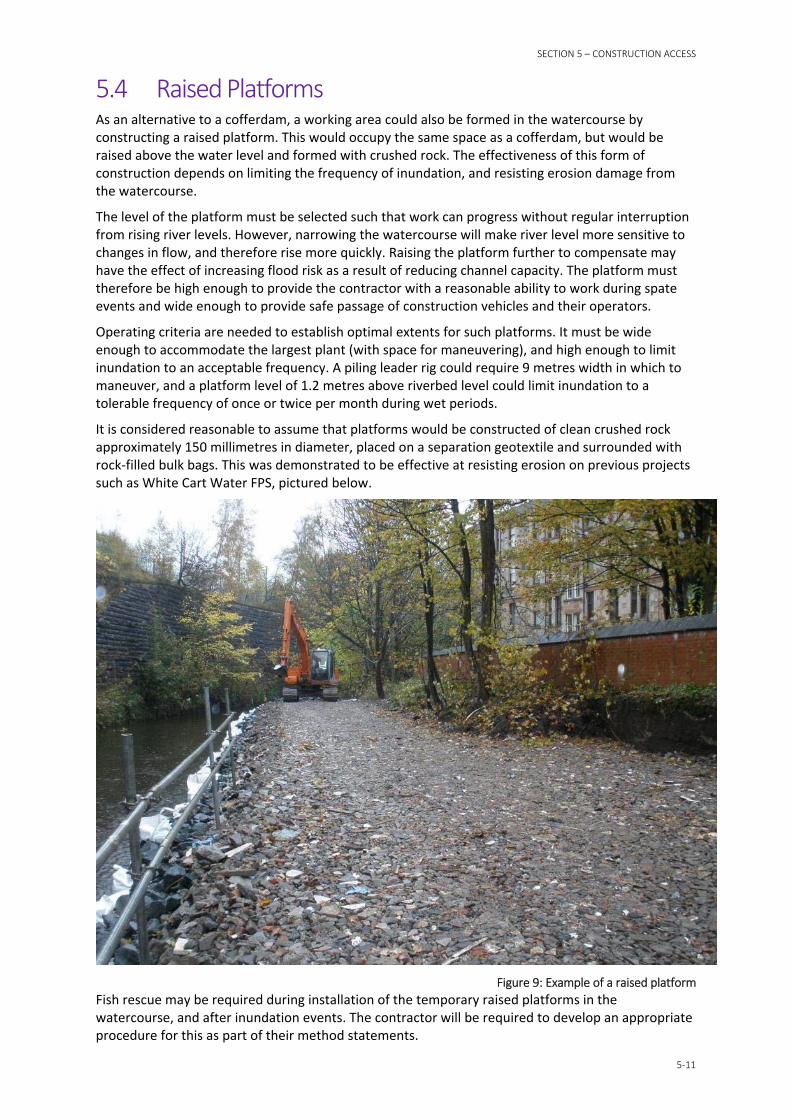
5.4 Raised Platforms As an alternative to a cofferdam, a working area could also be formed in the watercourse by constructing a raised platform. This would occupy the same space as a cofferdam, but would be raised above the water level and formed with crushed rock. The effectiveness of this form of construction depends on limiting the frequency of inundation, and resisting erosion damage from the watercourse.
The level of the platform must be selected such that work can progress without regular interruption from rising river levels. However, narrowing the watercourse will make river level more sensitive to changes in flow, and therefore rise more quickly. Raising the platform further to compensate may have the effect of increasing flood risk as a result of reducing channel capacity. The platform must therefore be high enough to provide the contractor with a reasonable ability to work during spate events and wide enough to provide safe passage of construction vehicles and their operators.
Operating criteria are needed to establish optimal extents for such platforms. It must be wide enough to accommodate the largest plant (with space for maneuvering), and high enough to limit inundation to an acceptable frequency. A piling leader rig could require 9 metres width in which to maneuver, and a platform level of 1.2 metres above riverbed level could limit inundation to a tolerable frequency of once or twice per month during wet periods.
It is considered reasonable to assume that platforms would be constructed of clean crushed rock approximately 150 millimetres in diameter, placed on a separation geotextile and surrounded with rock‐filled bulk bags. This was demonstrated to be effective at resisting erosion on previous projects such as White Cart Water FPS, pictured below.
Figure 9: Example of a raised platform
Fish rescue may be required during installation of the temporary raised platforms in the watercourse, and after inundation events. The contractor will be required to develop an appropriate procedure for this as part of their method statements.

SECTION 5 – CONSTRUCTION ACCESS
5‐12
5.5 Crossing Points Working areas in the watercourse would likely be parallel to the alignment of the flood defences. Access would be from the adjacent riverbank, except where this was not possible due to the presence of buildings or other barriers. In this event, crossing points would be required to access the working area from the opposite riverbank, and would most likely be formed from either:
A pipe bridge;
A Bailey bridge; or
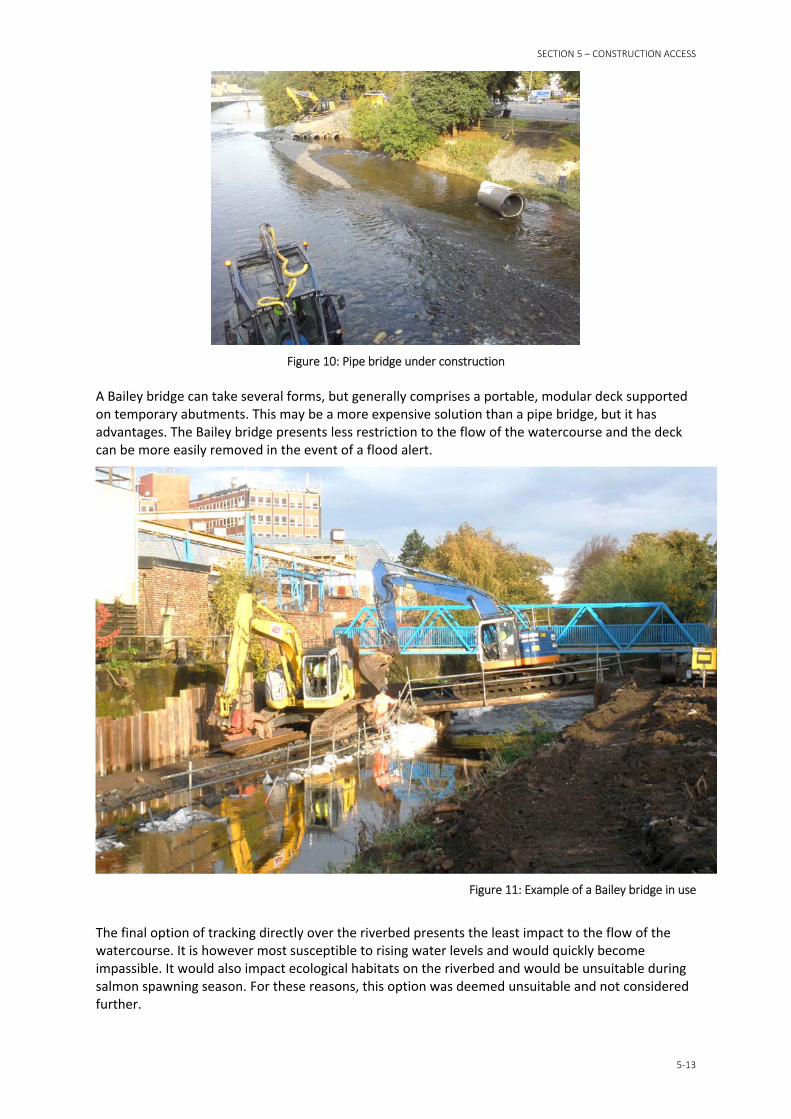
Tracking directly across Temporary works carried out in the River Teviot during September 2016 provided evidence of how a pipe crossing might perform under moderate flow conditions. A pipe bridge was constructed during low flow conditions, and comprised multiple concrete pipes of varying sizes, surrounded in 25‐40 millimetre diameter aggregate. The river level rose in response to a rainfall event, exceeding the capacity of the pipes and engulfing the working area. Prolonged high river levels washed out the aggregate, and washed the pipes downstream (they were later recovered).
This suggests that the effectiveness of pipes bridges is largely dependent on the materials used and construction. They may be unsuitable during prolonged wet periods on the River Teviot, and depending on the nature of their construction, could result in increased flood risk.
SECTION 5 – CONSTRUCTION ACCESS
5‐13
Figure 10: Pipe bridge under construction
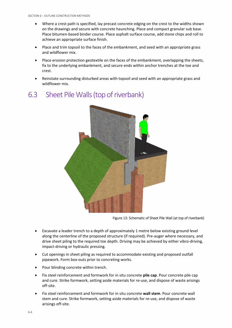
A Bailey bridge can take several forms, but generally comprises a portable, modular deck supported on temporary abutments. This may be a more expensive solution than a pipe bridge, but it has advantages. The Bailey bridge presents less restriction to the flow of the watercourse and the deck can be more easily removed in the event of a flood alert.
Figure 11: Example of a Bailey bridge in use
The final option of tracking directly over the riverbed presents the least impact to the flow of the watercourse. It is however most susceptible to rising water levels and would quickly become impassible. It would also impact ecological habitats on the riverbed and would be unsuitable during salmon spawning season. For these reasons, this option was deemed unsuitable and not considered further.

SECTION 5 – CONSTRUCTION ACCESS
5‐14
On consideration of the above options, it may be appropriate to use the Works Information to preclude the use of pipe bridges and tracking on the riverbed.
5.6 Dewatering of excavations Where working within the watercourse is required, it is considered unlikely that dewatering techniques would be used, and that they would be largely ineffective if attempted. Excavation works on the riverbanks, above river level, are also considered unlikely to require dewatering as the construction formation levels have been generally designed to occur above the ground water level observed during the ground investigation works.
Notwithstanding this, the contractor will be entitled to design their temporary works as they consider appropriate. If the contractor chooses to use dewatering as part of their temporary works, they will be responsible for complying with SEPA’s relevant General Binding Rules (GBRs), and for securing a licence where necessary.

SECTION 6
6‐1
Outline Construction Methods The following section outlines possible construction methods for the main forms of construction that are likely to form part of Hawick FPS. These methods are based on experience of similar construction activities which formed part of White Cart Water FPS, Broxburn FPS, Jedburgh (Skiprunning Burn) FPS, and Selkirk FPS between 2008 and 2016.
The form of construction for each work section was based on a number of factors, including cost, speed of construction, appearance, ground conditions, site access, and adjacent buildings. Full details of the selection process are included in the Preferred Scheme Report.
It should be noted that while outline construction methods are provided, the actual construction method may vary. This is because the contractor will be responsible for selecting the most appropriate construction method in accordance with their contractual and regulatory obligations. As part of these obligations they will also be required to submit detailed method statements for each construction activity to SEPA, SBC and CH2M for acceptance prior to the activity being carried out.
The contractor will be required to prepare a number of management plans and method statements for carrying out the works. For example, the contractor will be required to prepare a Site Waste Management Plan, which will contain details of how different waste will be handled in accordance with the waste hierarchy and regulatory requirements. Also, as part of their method statements, the contractor will be required to propose appropriate methods for managing sedimentation risk during periods of low flow.
6.1 General
6.1.1 Site Preparation Clear site of vegetation and fell trees, as necessary, which were not already removed during
advance trees felling works.
Locate/protect/divert, as necessary, any services which were not already dealt with during advance service diversion works. This includes individual connections to business and residential properties, and outfalls to the watercourse.
Remove street furniture, fencing and walls as necessary. Steel items may be removed by burning or cutting through foundations. Concrete and timber items may be removed manually or with mechanical excavator. Precautions will be taken to prevent debris entering the watercourse and waste arising will be disposed of off‐site.
Excavate bound surfaces, as necessary, to carry out the works.
Apply measures as necessary to minimise suspended solids, sediment, and contamination being released into the watercourse. This forms part of the contractor’s temporary works and may include attenuation lagoons and settlement tanks to manage runoff.
Strip topsoil using a mechanical excavator and store on site for later re‐use on site where possible. Where topsoil is unacceptable for re‐use on site, it will be disposed of off‐site.
Excavate to formation level using a mechanical excavator and store arisings on site for later re‐use on site where possible. Where arisings are unacceptable for re‐use on site, they will be disposed of off‐site.
Formation to be inspected and soft spots excavated and replaced with structural upfill. Arisings will be disposed of off‐site.

SECTION 6 – OUTLINE CONSTRUCTION METHODS
6‐2
6.1.2 Equipment and Materials The following list provides an indication of the likely equipment which may be used to construct the flood protection scheme:
360 degree tracked excavators
Wheeled backactors
Dumpers
Mobile cranes
Tracked piling machines
Vibrating roller compactors
Vibrating plate compactors
Burning and cutting equipment
Drilling and coring equipment
Mobile pumps
Mobile settlement tanks
Mobile generators
Mobile compressors
Mobile heaters
Tarmac planers and pavers
The following list provides an indication of the likely materials which may be used to construct the flood protection scheme:
Clay fill
Granular fill
Sands, gravels, and rock
Topsoil
Steel sheet piles
In situ concrete
Steel reinforcement
Geotextiles
Timber fencing
Metal fencing
Bitumen macadam
Plastic pipework and ductwork
Metal pipework
Concrete pipework
Mechanical pumps
Stonework, brickwork, and reconstituted stone products

SECTION 6 – OUTLINE CONSTRUCTION METHODS
6‐3
Precast concrete products
Glass products
Metal and plastic fixings and fixtures
Hydrocarbon‐based cellular products
Organic‐based coatings and sealants
Hydrocarbon‐based paints, coatings, and sealants
Lighting, wiring and fixtures
Fuel oils
Seed
Trees and plants
6.2 Embankments
Figure 12: Schematic of Embankment
Where a sheet pile core is specified, excavate a leader trench to a depth of approximately 1 metre below existing ground level along the centerline of the proposed structure (if required). Pre‐auger where necessary, and drive sheet piling to the required toe depth. Driving may be achieved by either vibro‐driving, impact‐driving or hydraulic pressing.
Lay flood defence drainage where required, which may comprise filter pipes in a granular trench, gully pots, gratings, precast concrete or plastic manholes, carrier pipes, headwall structures and flap valves. Cut openings in sheet piling as required to accommodate pipework. Cap pipework until such time as it is fully connected.
Place material separation geotextile across the extent of the excavation profile and fix to the underlying soil.
Where required, place anti‐burrowing geotextile across the extent of the excavation profile and provide sufficient material to wrap the entire surface of the embankment once placed.
Place, compact and trim embankment fill material in layers and to the side profiles shown on the drawings.
SECTION 6 – OUTLINE CONSTRUCTION METHODS
6‐4
Where a crest path is specified, lay precast concrete edging on the crest to the widths shown on the drawings and secure with concrete haunching. Place and compact granular sub base. Place bitumen‐based binder course. Place asphalt surface course, add stone chips and roll to achieve an appropriate surface finish.
Place and trim topsoil to the faces of the embankment, and seed with an appropriate grass and wildflower mix.
Place erosion protection geotextile on the faces of the embankment, overlapping the sheets, fix to the underlying embankment, and secure ends within anchor trenches at the toe and crest.
Reinstate surrounding disturbed areas with topsoil and seed with an appropriate grass and wildflower mix.
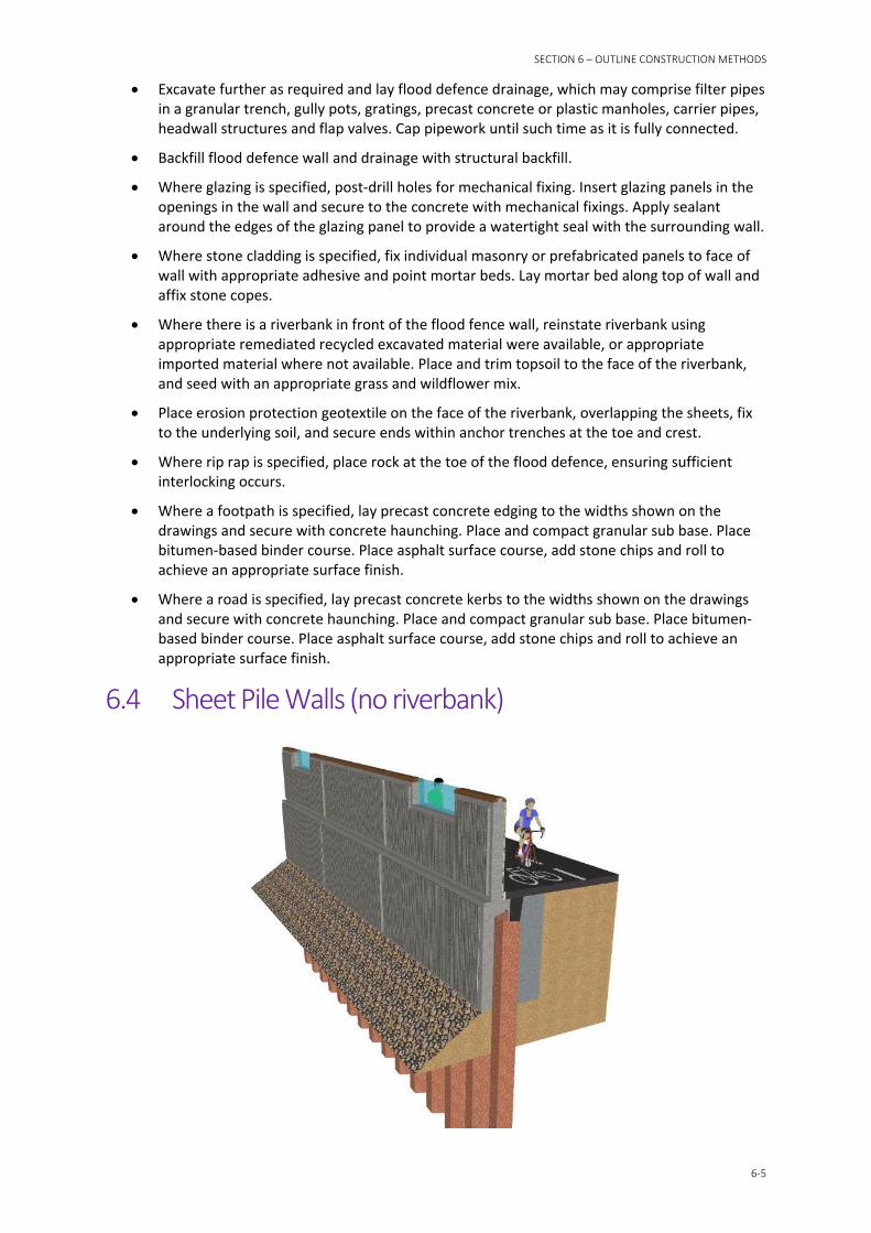
6.3 Sheet Pile Walls (top of riverbank)
Figure 13: Schematic of Sheet Pile Wall (at top of riverbank)
Excavate a leader trench to a depth of approximately 1 metre below existing ground level along the centerline of the proposed structure (if required). Pre‐auger where necessary, and drive sheet piling to the required toe depth. Driving may be achieved by either vibro‐driving, impact‐driving or hydraulic pressing.
Cut openings in sheet piling as required to accommodate existing and proposed outfall pipework. Form box‐outs prior to concreting works.
Pour blinding concrete within trench.
Fix steel reinforcement and formwork for in situ concrete pile cap. Pour concrete pile cap and cure. Strike formwork, setting aside materials for re‐use, and dispose of waste arisings off‐site.
Fix steel reinforcement and formwork for in situ concrete wall stem. Pour concrete wall stem and cure. Strike formwork, setting aside materials for re‐use, and dispose of waste arisings off‐site.
SECTION 6 – OUTLINE CONSTRUCTION METHODS
6‐5
Excavate further as required and lay flood defence drainage, which may comprise filter pipes in a granular trench, gully pots, gratings, precast concrete or plastic manholes, carrier pipes, headwall structures and flap valves. Cap pipework until such time as it is fully connected.
Backfill flood defence wall and drainage with structural backfill.
Where glazing is specified, post‐drill holes for mechanical fixing. Insert glazing panels in the openings in the wall and secure to the concrete with mechanical fixings. Apply sealant around the edges of the glazing panel to provide a watertight seal with the surrounding wall.
Where stone cladding is specified, fix individual masonry or prefabricated panels to face of wall with appropriate adhesive and point mortar beds. Lay mortar bed along top of wall and affix stone copes.
Where there is a riverbank in front of the flood fence wall, reinstate riverbank using appropriate remediated recycled excavated material were available, or appropriate imported material where not available. Place and trim topsoil to the face of the riverbank, and seed with an appropriate grass and wildflower mix.
Place erosion protection geotextile on the face of the riverbank, overlapping the sheets, fix to the underlying soil, and secure ends within anchor trenches at the toe and crest.
Where rip rap is specified, place rock at the toe of the flood defence, ensuring sufficient interlocking occurs.
Where a footpath is specified, lay precast concrete edging to the widths shown on the drawings and secure with concrete haunching. Place and compact granular sub base. Place bitumen‐based binder course. Place asphalt surface course, add stone chips and roll to achieve an appropriate surface finish.
Where a road is specified, lay precast concrete kerbs to the widths shown on the drawings and secure with concrete haunching. Place and compact granular sub base. Place bitumen‐based binder course. Place asphalt surface course, add stone chips and roll to achieve an appropriate surface finish.
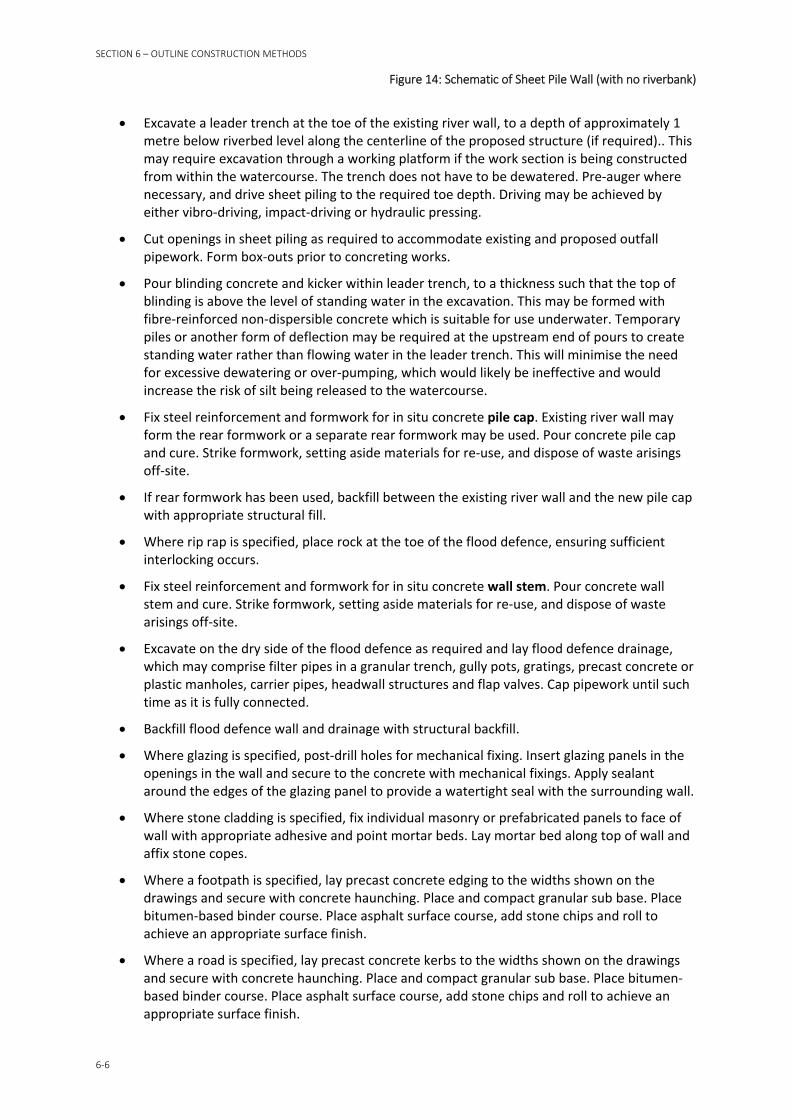
6.4 Sheet Pile Walls (no riverbank)
SECTION 6 – OUTLINE CONSTRUCTION METHODS
6‐6
Figure 14: Schematic of Sheet Pile Wall (with no riverbank)
Excavate a leader trench at the toe of the existing river wall, to a depth of approximately 1 metre below riverbed level along the centerline of the proposed structure (if required).. This may require excavation through a working platform if the work section is being constructed from within the watercourse. The trench does not have to be dewatered. Pre‐auger where necessary, and drive sheet piling to the required toe depth. Driving may be achieved by either vibro‐driving, impact‐driving or hydraulic pressing.
Cut openings in sheet piling as required to accommodate existing and proposed outfall pipework. Form box‐outs prior to concreting works.
Pour blinding concrete and kicker within leader trench, to a thickness such that the top of blinding is above the level of standing water in the excavation. This may be formed with fibre‐reinforced non‐dispersible concrete which is suitable for use underwater. Temporary piles or another form of deflection may be required at the upstream end of pours to create standing water rather than flowing water in the leader trench. This will minimise the need for excessive dewatering or over‐pumping, which would likely be ineffective and would increase the risk of silt being released to the watercourse.
Fix steel reinforcement and formwork for in situ concrete pile cap. Existing river wall may form the rear formwork or a separate rear formwork may be used. Pour concrete pile cap and cure. Strike formwork, setting aside materials for re‐use, and dispose of waste arisings off‐site.
If rear formwork has been used, backfill between the existing river wall and the new pile cap with appropriate structural fill.
Where rip rap is specified, place rock at the toe of the flood defence, ensuring sufficient interlocking occurs.
Fix steel reinforcement and formwork for in situ concrete wall stem. Pour concrete wall stem and cure. Strike formwork, setting aside materials for re‐use, and dispose of waste arisings off‐site.
Excavate on the dry side of the flood defence as required and lay flood defence drainage, which may comprise filter pipes in a granular trench, gully pots, gratings, precast concrete or plastic manholes, carrier pipes, headwall structures and flap valves. Cap pipework until such time as it is fully connected.
Backfill flood defence wall and drainage with structural backfill.
Where glazing is specified, post‐drill holes for mechanical fixing. Insert glazing panels in the openings in the wall and secure to the concrete with mechanical fixings. Apply sealant around the edges of the glazing panel to provide a watertight seal with the surrounding wall.
Where stone cladding is specified, fix individual masonry or prefabricated panels to face of wall with appropriate adhesive and point mortar beds. Lay mortar bed along top of wall and affix stone copes.
Where a footpath is specified, lay precast concrete edging to the widths shown on the drawings and secure with concrete haunching. Place and compact granular sub base. Place bitumen‐based binder course. Place asphalt surface course, add stone chips and roll to achieve an appropriate surface finish.
Where a road is specified, lay precast concrete kerbs to the widths shown on the drawings and secure with concrete haunching. Place and compact granular sub base. Place bitumen‐based binder course. Place asphalt surface course, add stone chips and roll to achieve an appropriate surface finish.
SECTION 6 – OUTLINE CONSTRUCTION METHODS
6‐7
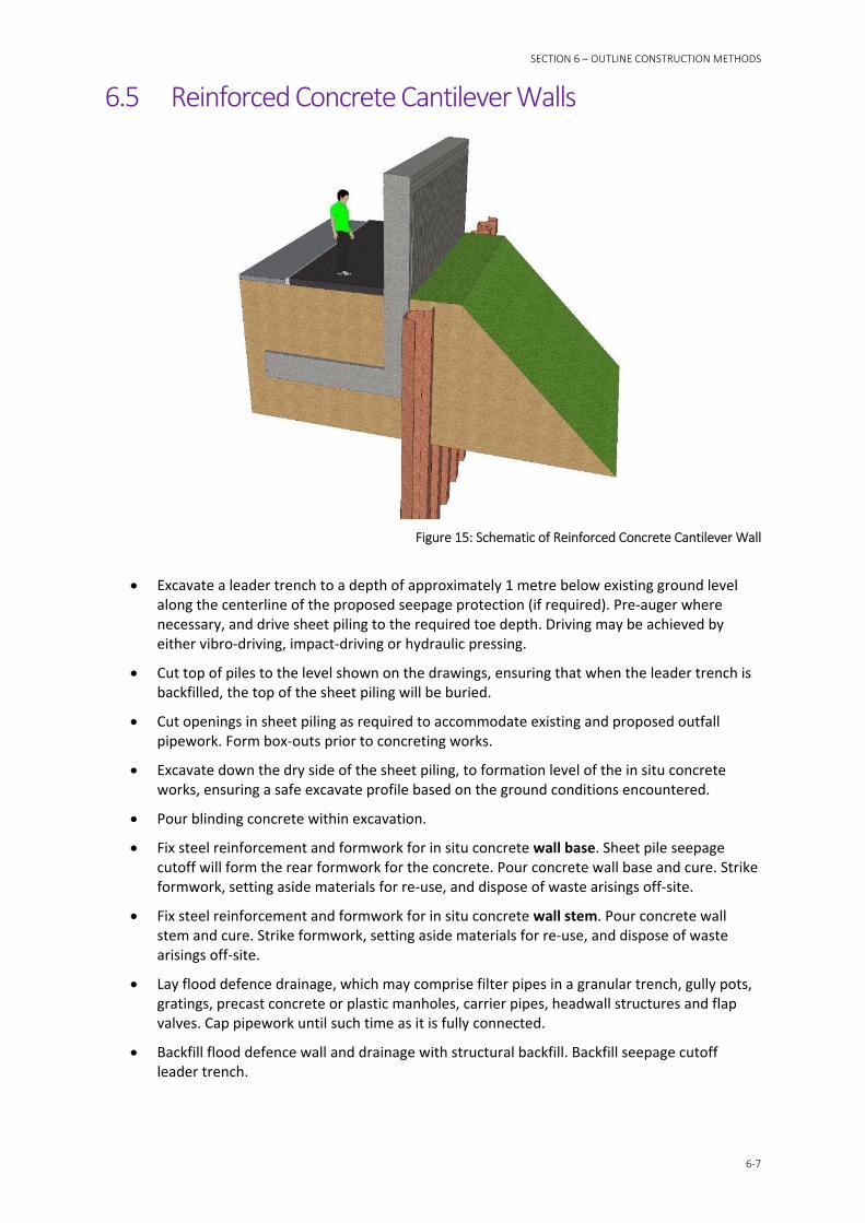
6.5 Reinforced Concrete Cantilever Walls
Figure 15: Schematic of Reinforced Concrete Cantilever Wall
Excavate a leader trench to a depth of approximately 1 metre below existing ground level along the centerline of the proposed seepage protection (if required). Pre‐auger where necessary, and drive sheet piling to the required toe depth. Driving may be achieved by either vibro‐driving, impact‐driving or hydraulic pressing.
Cut top of piles to the level shown on the drawings, ensuring that when the leader trench is backfilled, the top of the sheet piling will be buried.
Cut openings in sheet piling as required to accommodate existing and proposed outfall pipework. Form box‐outs prior to concreting works.
Excavate down the dry side of the sheet piling, to formation level of the in situ concrete works, ensuring a safe excavate profile based on the ground conditions encountered.
Pour blinding concrete within excavation.
Fix steel reinforcement and formwork for in situ concrete wall base. Sheet pile seepage cutoff will form the rear formwork for the concrete. Pour concrete wall base and cure. Strike formwork, setting aside materials for re‐use, and dispose of waste arisings off‐site.
Fix steel reinforcement and formwork for in situ concrete wall stem. Pour concrete wall stem and cure. Strike formwork, setting aside materials for re‐use, and dispose of waste arisings off‐site.
Lay flood defence drainage, which may comprise filter pipes in a granular trench, gully pots, gratings, precast concrete or plastic manholes, carrier pipes, headwall structures and flap valves. Cap pipework until such time as it is fully connected.
Backfill flood defence wall and drainage with structural backfill. Backfill seepage cutoff leader trench.

SECTION 6 – OUTLINE CONSTRUCTION METHODS
6‐8
Where glazing is specified, post‐drill holes for mechanical fixing. Insert glazing panels in the openings in the wall and secure to the concrete with mechanical fixings. Apply sealant around the edges of the glazing panel to provide a watertight seal with the surrounding wall.
Where stone cladding is specified, fix individual masonry or prefabricated panels to face of wall with appropriate adhesive and point mortar beds. Lay mortar bed along top of wall and affix stone copes.
Where there is a riverbank in front of the flood fence wall, reinstate riverbank using appropriate remediated recycled excavated material were available, or appropriate imported material where not available. Place and trim topsoil to the face of the riverbank, and seed with an appropriate grass and wildflower mix.
Place erosion protection geotextile on the face of the riverbank, overlapping the sheets, fix to the underlying soil, and secure ends within anchor trenches at the toe and crest.
Where rip rap is specified, place rock at the toe of the flood defence, ensuring sufficient interlocking occurs.
Where a footpath is specified, lay precast concrete edging to the widths shown on the drawings and secure with concrete haunching. Place and compact granular sub base. Place bitumen‐based binder course. Place asphalt surface course, add stone chips and roll to achieve an appropriate surface finish.
Where a road is specified, lay precast concrete kerbs to the widths shown on the drawings and secure with concrete haunching. Place and compact granular sub base. Place bitumen‐based binder course. Place asphalt surface course, add stone chips and roll to achieve an appropriate surface finish.
6.6 Culverts Set up mobile pump(s) and form temporary sump at upstream end of the proposed
culverting works. Over‐pump the working area, returning the flow of water to beyond the downstream extent of the works.
Excavate existing channel to the required formation level, setting aside river cobbles for re‐use if appropriate. Demolish or partly demolish existing riverbank structures as necessary to concrete the proposed culvert.
Lay new culvert sections within the excavation, ensuring securing a good seal between lengths.
Backfill around culvert with mass concrete or structural backfill, as specified.
Pour blinding concrete for connections at upstream and downstream ends of culvert.
Fix steel reinforcement and formwork for in situ concrete connection chambers. Pour concrete connection chambers and cure. Strike formwork, setting aside materials for re‐use, and dispose of waste arisings off‐site.
Stop over‐pumping and return flow of water to new connection chamber and culvert.
Backfill crown of culvert with structural backfill, dress with topsoil and seed with an appropriate grass and wildflower mix.
Where specified, fit manhole covers to connection chambers.
Reinstate surrounding disturbed areas with topsoil and seed with an appropriate grass and wildflower mix.
SECTION 6 – OUTLINE CONSTRUCTION METHODS
6‐9
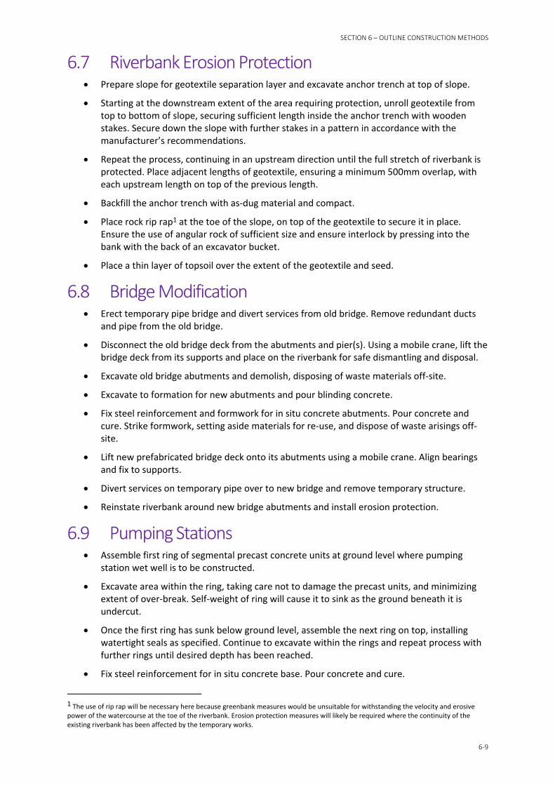
6.7 Riverbank Erosion Protection Prepare slope for geotextile separation layer and excavate anchor trench at top of slope.
Starting at the downstream extent of the area requiring protection, unroll geotextile from top to bottom of slope, securing sufficient length inside the anchor trench with wooden stakes. Secure down the slope with further stakes in a pattern in accordance with the manufacturer’s recommendations.
Repeat the process, continuing in an upstream direction until the full stretch of riverbank is protected. Place adjacent lengths of geotextile, ensuring a minimum 500mm overlap, with each upstream length on top of the previous length.
Backfill the anchor trench with as‐dug material and compact.
Place rock rip rap1 at the toe of the slope, on top of the geotextile to secure it in place. Ensure the use of angular rock of sufficient size and ensure interlock by pressing into the bank with the back of an excavator bucket.
Place a thin layer of topsoil over the extent of the geotextile and seed.
6.8 Bridge Modification Erect temporary pipe bridge and divert services from old bridge. Remove redundant ducts
and pipe from the old bridge.
Disconnect the old bridge deck from the abutments and pier(s). Using a mobile crane, lift the bridge deck from its supports and place on the riverbank for safe dismantling and disposal.
Excavate old bridge abutments and demolish, disposing of waste materials off‐site.
Excavate to formation for new abutments and pour blinding concrete.
Fix steel reinforcement and formwork for in situ concrete abutments. Pour concrete and cure. Strike formwork, setting aside materials for re‐use, and dispose of waste arisings off‐site.
Lift new prefabricated bridge deck onto its abutments using a mobile crane. Align bearings and fix to supports.
Divert services on temporary pipe over to new bridge and remove temporary structure.
Reinstate riverbank around new bridge abutments and install erosion protection.
6.9 Pumping Stations Assemble first ring of segmental precast concrete units at ground level where pumping
station wet well is to be constructed.
Excavate area within the ring, taking care not to damage the precast units, and minimizing extent of over‐break. Self‐weight of ring will cause it to sink as the ground beneath it is undercut.
Once the first ring has sunk below ground level, assemble the next ring on top, installing watertight seals as specified. Continue to excavate within the rings and repeat process with further rings until desired depth has been reached.
Fix steel reinforcement for in situ concrete base. Pour concrete and cure.
1 The use of rip rap will be necessary here because greenbank measures would be unsuitable for withstanding the velocity and erosive power of the watercourse at the toe of the riverbank. Erosion protection measures will likely be required where the continuity of the existing riverbank has been affected by the temporary works.

SECTION 6 – OUTLINE CONSTRUCTION METHODS
6‐10
Excavate to formation level for adjacent valve chamber and pour blinding concrete.
Fix steel reinforcement and formwork for in situ concrete valve chamber. Pour concrete and cure. Strike formwork, setting aside materials for re‐use, and dispose of waste arisings off‐site.
Excavate between wet well and valve chamber where connecting pipework is to be laid. Breakout openings in wet well for pipework to valve chamber, install pipework and seal openings around pipes. Backfill pipe trench.
Excavate between valve chamber and outfall location (opening in flood defence wall) where connecting pipework is to be laid. Lay pipework and seal openings around pipes. Backfill pipe trench.
Install pump(s) in wet well and valve(s) in valve chamber, and associated equipment.
Install watertight seals around top of wet well and valve chamber, and lift prefabricated covered slabs with access covers into place.
Backfill around valve chamber, using appropriate structural fill.
Install additional mechanical and electrical equipment.
Reinstate surrounding surfaces as appropriate.

SECTION 7
7‐1
Impact of Construction Sequence and Timing The project is complex in its nature, incorporating aspects of construction, logistics, river management, traffic management, and public interface. The work is spread over a number of discrete areas across Hawick, and the contractor will be responsible for determining the programme and construction sequence for the works in accordance with their contractual and regulatory obligations. There are innumerable possible combinations for this, therefore it is not possible to determine with any certainty the construction sequence prior to a contractor being appointed.
7.1 Contract Constraints Notwithstanding this, contract conditions can be imposed on the contractor to constrain how they are permitted to sequence the work. These constraints should be used with caution however, as overuse of contractual constraints can increase the duration, cost, and complexity of the works and even cause certain operations to become impossible to construct. Taking this into consideration, the following combinations and sequences of work may be discounted due to contractual constraints which are likely be placed on the contractor:
Where work sections on directly opposite riverbanks are both to be constructed from working areas in the watercourse, these may be prohibited from occurring at the same time due to the excessive constriction which would be imposed on the watercourse.
Where a work section will require traffic management (such as diversions, and one way traffic under traffic light control), and where another work section affects a likely alternative route, these two work sections may be prohibited from occurring at the same time.
Where a work section will require traffic management to a long length of road, the contractor may be restricted to the length of working area which can be closed to the public at any one time, thereby limiting the extent of the traffic management.
Due to the effect that haul roads in the watercourse can have on the flow of water, a limit may be imposed on the total length of such haul roads that is permitted to be in place at any one time.
Specific construction activities which produce considerable noise, and which are in proximity to schools, are likely to be restricted during major examination periods.
Work which disturbs the riverbed, such as construction or removal of cofferdams or raised platforms, is likely to be restricted during salmon spawning season.
Prior to felling trees during bird nesting season, supplementary surveys for breeding birds may be required to comply with relevant legislation.
Where bridges are closed as a result of the works, adjacent bridges must remain open to pedestrians at all times.
Depending on the outcome of discussions with SEPA, RTC and SNH, some constraints may be placed on certain activities at key salmon spawning areas during sensitive spawning periods, and this is discussed further in the Environmental Statement. To be confirmed.
7.2 Temporary Flood Protection The sequence of construction may have the effect of temporarily lowering the standard of protection of locations where flood defences have yet to be constructed. Where a flood defence is

SECTION 7 – IMPACT OF CONSTRUCTION SEQUENCE AND TIMING
7‐2
constructed on one riverbank, it may direct more flow to the opposite riverbank where defences have yet to be constructed, lowering the standard of protection there until both sides are complete. Likewise, defences completed on both sides may channel flow further downstream, lowering the standard of protection there until their defences are completed.
Temporary changes to the standard of protection is an inevitable consequence of constructing large flood protection schemes, since all defences cannot all be constructed simultaneously. The risk may be mitigated by providing temporary flood defences at locations where the permanent works have not yet been completed, or leaving out small sections of otherwise complete sections of flood defences. The level of such protection could be selected such that the same standard of protection is maintained as existed before the project began. Establishing this level would require hydraulic modelling to be carried out by the Employer, based on a construction sequence provided by the contractor.
Provision of temporary defences could be incorporated in the main works contract. This could require the contractor to deploy temporary defences over specified stretches based on his construction sequence, or simply to maintain ready supplies of materials which could be easily and effectively deployed in the event of a flood alert.

SECTION 8
8‐1
Reinstatement
8.1 Residential Gardens The required standard of reinstatement for residential gardens is a subjective matter, particular to each landowner, and not suited to being carried out by a large engineering contractor. Experience indicates that a basic level of reinstatement can be consistently achieved by the contractor, comprising topsoil and hard landscaping such as gravel or paving. Beyond that, it is proposed that the landowner may be better placed to arrange soft landscaping to suit their needs and expectations, with the costs of this provided for within the scheme. The landowner will also most likely be in a better position to water and maintain the soft landscaping to meet their expectations.
Where the landowner is unable to arrange reinstatement of soft landscaping themselves, it may be possible to engage a specialist contractor for this work, with the costs provided for within the scheme.
8.2 Amenity Areas Public amenity areas such as parks, playgrounds and grass verges will be reinstated by the contractor. A similar form of landscaping could be provided, or alternatives developed in consultation with the relevant planning authorities within SBC. This will form part of the detailed design phase of the project.
8.3 Roads and Footpaths Where roads are open to both the public and the contractor, experience indicates that it is difficult to attribute deterioration to construction traffic and thereby require the contractor to carry out repairs at their expense. This is particularly the case where roads are used by buses and HGVs.
One option is to prescribe within the contract which roads are expected to require reinstatement and to what standard. Where reinstatement is not necessary, this activity could later be removed from the contract, although experience indicates that the true cost may not be fully recovered by doing this.
A second option is to remove road reinstatement from the main works contract and make provision for it to be carried out separately by SBC. This would ensure that cost is only incurred where reinstatement is actually necessary, and is likely to be a more cost effective option as the extra fees associated with NEC compensation events would not be incurred.
Where roads are within the site boundary and excavation by the contractor is required, it is more straightforward to include reinstatement of these surfaces under the contract. Likewise, where damage or deterioration is clearly due to the contractor (such as track marks or concrete spills) reinstatement of these areas can more easily be included in the contract. A comprehensive dilapidation survey in advance of the contractor taking possession of the relevant Working Area is essential.
8.4 Existing Structures As described in Section 5.1, many of the work sections are in close proximity to existing structures, and the risk of damage should be considered carefully. The NEC Engineering and Construction Contract Clause 80.1 states that the following is an Employer’s risk:
“Claims, proceedings, compensation and costs payable which are due to use or occupation of the Site by the works or for the purpose of the works which is the unavoidable result of the works.”

SECTION 8 – REINSTATEMENT
8‐2
Damage caused by the Contractor providing the works is therefore only a Contractor’s risk if it is deemed to be avoidable. Experience indicates that, particularly in the case of old structures, this can be difficult to resolve after the fact.
It is therefore recommended that provision be made within the contract such that the Contractor is required to declare that their method of working has been selected such that no damage or deterioration shall occur to any building, structure, property or the natural environment as an unavoidable result of the works. Failure to make this declaration would give the Employer cause to reject the Contractor’s method statement.
Notwithstanding the above provision, it is also recommended that allowance be made within the monetised risk register for claims, proceedings, compensation and costs payable due to damage of this nature.

Appendix A Possible In‐channel Work


SV
SSDrawn By : Checked By : Approved By :
Revision
Drawing Scale :
Drawing No. :
Drawing :
Project :
1
OR
Hawick Flood Protection Scheme
CH2MCity Park368 Alexandra ParadeGlasgow, G31 3AUUnited Kingdomwww.ch2m.com
ClientScottish Borders Council
Document Path: \\glafpp01\Projects\Water\663475 - Hawick FPS\Calcs\GIS\41 Construction Methodology\Construction_Methodology.mxd
Date: 07/03/2017Date: 07/03/2017Date: 07/03/2017
1:2,500
`
` `
¯
KEYFlood WallEmbankmentBridge to be Raised
!Access Point to RiverCulvertsMill Lade BackfillingDry Working AreasIn-River Working AreasWorks FootprintSite BoundarySite Compounds
¯
0 10050Meters
Reproduced by permission of Ordnance Survey on behalf of HMSO.© Crown copyright [and database rights] 2017 OS (100023423).
Map Centre: 349814 614502,
663475_HP3-CH2-MUL-CM-DR-C-0001
Construction MethodologyFigure A3a

SV
SSDrawn By : Checked By : Approved By :
Revision
Drawing Scale :
Drawing No. :
Drawing :
Project :
1
OR
Hawick Flood Protection Scheme
CH2MCity Park368 Alexandra ParadeGlasgow, G31 3AUUnited Kingdomwww.ch2m.com
ClientScottish Borders Council
Document Path: \\glafpp01\Projects\Water\663475 - Hawick FPS\Calcs\GIS\41 Construction Methodology\Construction_Methodology.mxd
Date: 07/03/2017Date: 07/03/2017Date: 07/03/2017
1:2,500
`
`
`
`
¯
KEYFlood WallEmbankmentBridge to be Raised
!Access Point to RiverCulvertsMill Lade BackfillingDry Working AreasIn-River Working AreasWorks FootprintSite BoundarySite Compounds
¯
0 10050Meters
Reproduced by permission of Ordnance Survey on behalf of HMSO.© Crown copyright [and database rights] 2017 OS (100023423).
Map Centre: 350403 614985,
663475_HP3-CH2-MUL-CM-DR-C-0002
Construction MethodologyFigure A3b

SV
SSDrawn By : Checked By : Approved By :
Revision
Drawing Scale :
Drawing No. :
Drawing :
Project :
1
OR
Hawick Flood Protection Scheme
CH2MCity Park368 Alexandra ParadeGlasgow, G31 3AUUnited Kingdomwww.ch2m.com
ClientScottish Borders Council
Document Path: \\glafpp01\Projects\Water\663475 - Hawick FPS\Calcs\GIS\41 Construction Methodology\Construction_Methodology.mxd
Date: 07/03/2017Date: 07/03/2017Date: 07/03/2017
1:2,500
`
¯
KEYFlood WallEmbankmentBridge to be Raised
!Access Point to RiverCulvertsMill Lade BackfillingDry Working AreasIn-River Working AreasWorks FootprintSite BoundarySite Compounds
¯
0 10050Meters
Reproduced by permission of Ordnance Survey on behalf of HMSO.© Crown copyright [and database rights] 2017 OS (100023423).
Map Centre: 351230 615491,
663475_HP3-CH2-MUL-CM-DR-C-0003
Construction MethodologyFigure A3c

SV
SSDrawn By : Checked By : Approved By :
Revision
Drawing Scale :
Drawing No. :
Drawing :
Project :
1
OR
Hawick Flood Protection Scheme
CH2MCity Park368 Alexandra ParadeGlasgow, G31 3AUUnited Kingdomwww.ch2m.com
ClientScottish Borders Council
Document Path: \\glafpp01\Projects\Water\663475 - Hawick FPS\Calcs\GIS\41 Construction Methodology\Construction_Methodology.mxd
Date: 07/03/2017Date: 07/03/2017Date: 07/03/2017
1:2,500
¯
KEYFlood WallEmbankmentBridge to be Raised
!Access Point to RiverCulvertsMill Lade BackfillingDry Working AreasIn-River Working AreasWorks FootprintSite BoundarySite Compounds
¯
0 10050Meters
Reproduced by permission of Ordnance Survey on behalf of HMSO.© Crown copyright [and database rights] 2017 OS (100023423).
Map Centre: 352058 615817,
663475_HP3-CH2-MUL-CM-DR-C-0004
Construction MethodologyFigure A3d