having sufficient number of experienced personnel, tech
TRANSCRIPT

1
Name of the Project Estimated Cost
Construction of RSETI Building at “Sheohar” Muzaffarpur.
107.5 Lakhs
Bank of Baroda invites sealed tenders on item rate basis from competent Contractors having sound
technical and financial capacity for for Construction of RSETI building at “Sheohar”
Muzaffarpur.
Contractors who are desirous of tendering the above work and fulfill the following Civil work
requirements shall be eligible to apply:
Average Annual financial turnover of the firm during the last 3 years, ending 31st March
2016, should be at least Rs50 lacs supported with audited balance sheets.
Experience of having successfully completed similar jobs work during the last 5 years (as on
31.03.2016), should be either of the following:
1. Three similar completed works each costing not less than Rs. 43 Lacs.
OR
2. Two similar completed works each costing not less than Rs. 53.75 Lacs.
OR
3. One similar completed work costing not less than Rs. 86Lacs.
Out of the above works, at least one work should be executed in Govt. deptt./ PSU‟s/ Autonomous
bodies/ Banks & Financial Institutions.
Having sufficient number of experienced personnel, technical know-how, equipment, instrument and
other resources, to complete the project well in time with superior quality of materials &
workmanship as per standard specifications.
Applications by those firms who do not submit Performance Certificates
from their previous employers are liable to be summarily rejected.
Tender complete in all respects along with relevant documents, information & in Bank‟s format duly
Super scribing of technical and Financial bid in separate envelope for Construction of RSETI
building at “Sheohar” Muzaffarpur. on envelope should reach at the following address on or
before 15/07/16 @ 4PM.
The Regional Manager, Bank of Baroda Muzaffarpur
2nd floor Krishna,Honda Building Akharaghat Road
Muzaffarpur -842001

2
Signature of contractor
Instructions to the Applicants for furnishing information as a part of application for pre-
qualification.
1. Intending applicants are required to submit their application in Duplicate with full bio-data
giving details about their organisation, experience, technical personnel in their organisation,
competence and adequate evidence of their financial standing, etc. in the enclosed form which
will be kept confidential.
2. While deciding upon the pre-qualification of Contractors, great emphasis will be given on the
ability and competence of applicants to do good quality works within the specified time
schedule and close co-ordination with other agencies.
3. Decision of the Bank in regard to selection of Contractors for issue of tender documents will be
final. The Bank is not bound to assign any reason for acceptance / rejection of any applications.
Disputes, if any, shall be within the jurisdiction of courts in Patna.
4. Each page of the tender page shall be signed. The application shall be signed by person/ persons
on behalf of the organisation having necessary authorisation/ Power of Attorney to do so
(Certified copies to be enclosed).
5. If the space in the Performa is insufficient for furnishing full details, such information may be
supplemented on separate sheets of paper, stating therein the part of the Performa and serial
number. Separate sheets shall be used for each aprt. However the format shall be as per
Performa.
6. Applications containing false incomplete and / or inadequate information are liable to be
rejected. Also mare fulfilment of eligibility criteria does not guarantee selection.
7. While filling up the application with regard to the list of important projects completed or on
hand, the applicants shall include those works which are individually costing not less than 40%
of the estimated cost shown against individual trade herein above.
8. Clarification, if any, may be obtained from the office of R.M ( Muzaffarpur Region), Bank of
Baroda, Regional Office, Muzaffarpur.
9 Canvassing in any form in connection with pre-qualification is strictly prohibited and the tender
of such persons/ organizations who resort to canvassing will be liable to rejection.
10 The tenders, which are received after due date and time, are liable to be rejected.
11 Bank reserves the right to reject any/ all the tender without assigning any reason whatsoever
therefore.
Signature of the Applicant
With Address & Seal
B.O.B REGIONAL OFFICE MUZAFFARPUR
2nd
FLOOR KRISHNA HONDA BUILDING
AKHARAGHAT ROAD,
MUZAFFARPUR - 842001.
BIHAR

3
Signature of contractor
TO BE SUBMITTED IN ENVELOP NO - 01
B.O.B REGIONAL OFFICE MUZAFFARPUR
2nd
FLOOR KRISHNA HONDA BUILDING
AKHARAGHAT ROAD,
MUZAFFARPUR - 842001.
BIHAR
TECHNO COMMERCIAL BID - PART l
TENDER DOCUMENT FOR CONSTRUCTION OF RSETI BUILDING AT
“SHEOHAR” MUZAFFARPUR
Tender Documents Consisting of:
NIT, General Rules of Instructions for the Guidance of Tenderers,
Form of Tender, Articles of Agreement,
General Conditions of Contract, Special Conditions of Contract,
Technical Specifications
and Schedule of Quantities
M/S
________________________________________________
________________________________________________
________________________________________________
________________________________________________
ARCHITECT:
M/S RAM LAKSHMAN & SKY ASSOCIATE
Architect, Interior Designer & Valuer
„ASHA‟ 9Th
Avenue, South park, Bistupur
Jamshedpur-831001
Contact Persons:
Jaideep Naryan (S.r Technical Manager)-0612-2557610
S. K Sinha (Director RSETI Sheohar) -0622-257035

4
Signature of contractor
GENERAL INDEX
Sl.No. Description Page No. 1 2 3 4 5 6 7 8 9 10 11
12 13 14 15 16 17 18 19 20 21 22 23
24 25
26
Pre-qualification & Basic Information Notice Inviting Tender Instructions to the Tenderers Form of Tender Articles of Agreement General Conditions of Contract Appendix Special Conditions of Contract Safety Code Proforma of “Running A/C Bill” Account of Secured Advance if admissible on materials held at site
by the contractor Certificate Proforma for Memorandum for Payment Proforma of Certificate of Payment by Architects Details Insurance Polices Proforma of Hindrance Register Proforma of Bank Guarantee in Lieu of Security Deposit Proforma of Undertaking in connection with Payment of advance on
materials brought by the contractor to the site Proforma for Application by Contractor for Extension of Time Maintenance of Records Technical Specification for Civil Works List of materials of Approved Makes/Brand Technical Specification for Electrical Works Schedule of Items Price Bid , B.O.Q & Tender Drawings
5-12 13-14 15-17 18-19 20-22 23-43
44 45-49
50 51
52 53
54-55 56 57 58
59-60 61-63
64 65
66-171 172-174 175-191 192-193 195-255

5
Signature of contractor
Pre-qualification & Basic Information
1. Intending Applicants are required to submit their applications in the prescribed format and with full particulars giving details about their organization, experience, technical personnel in their organization which will be kept confidential.
2. While deciding upon the prequalification of contractors, emphasis will be given on the ability and competence of applicants to do good quality works within the specified time schedule and in close co-ordination with other agencies.
3. Each page of the application shall be signed by the Applicant. The application shall be signed by person / persons on behalf of the organization having necessary authorization / Power of Attorney to do so.
4. If the space in this form is insufficient for furnishing full details, such information may be continued on separate sheets of paper, stating therein the part of the form and serial number. Separate sheets shall be used for each part and a proper reference with page number must be indicated in the main form of application. The applicant should, however, enclose the application form collected from the Bank or down loaded from web site along with the application.
5. Applications containing false and / or inadequate information are liable for rejection.
6. While filling up the application with regard to the list of important projects completed (or on hand), the applicants shall include projects relating to Corporative / Administrative buildings costing not less than Rs.43 lacs each and shall mention all features and services of the project handled by the applicant such as number of storey of the building, type of foundation and super-structure, total constructed area, services provided electrical, plumbing, Fire protection, Air-conditioning, elevators etc.
7. Clarifications, if any required, may be obtained from Jaideep Naryan (Sr. Tech. Manager Tel. No. 0612-2557610, or Director RSETI Sheohar Tel No-0622-257053 .The minimum general Pre qualification criteria shall be as stipulated in this form of application. However, fulfillment of minimum eligibility criteria will not entitle for Prequalification as Pre-qualification will be done after taking into account various parameters including receipt of satisfactory reports from clients. The firms shall not have any discouraging / adverse report against their past performance.
8. Applicants shall furnish documentary evidence / certificates in support of their claims of work undertaken and work in hand, failing which the application will be liable for rejection.
9. Decision of the Bank in regard to pre-qualification of Contractors shall be final. The Bank reserves the right to reject any or all applications without assigning any reason thereto.

6
Signature of contractor
Minimum Pre-qualification Criteria
a) The firm should have minimum 7 years experience in the field of construction of buildings works.
b) The average financial turn over during last three years from ending 31st March of the previous financial year should be Rs 50 Lacs per year.
c) The firm should have technical set up with adequate organizational structure comprising of skilled staff having knowledge and experience to execute such type of works and also adequate number of Civil Engineers, Electrical Engineers.
d) The firm should have adequate machinery / equipment to carry out work of such magnitude.
e) The firm must have minimum experience of having successfully completed buildings during last 5 years.
i) At least 3 similar projects costing minimum Rs. 43.0 lacs each At least one work should be carried with Govt / PSU sectors from above three works.
or ii) At least 2 similar projects costing minimum Rs. 53.75 lacs each. At least one work should be complete with GOVT / PSU sectors from above two works.
or iii) At least one similar project costing minimum Rs. 86 lacs should be complete with Govt / PSU sector.
f) The expression similar project shall mean the Collage building / Hostel building relating to construction of multi storied commercial / residential building comprising of Civil & Plumbing work, Electrical work, The firm should enclose documentary evidence in support of the experience details furnished by them stating the value of work and area of construction and other salient features of work.
g) The firm should preferably have experience in handling projects comprising construction work of Govt./ Public Sector Undertakings / Nationalized Banks and shall not have any discouraging /adverse report about their firm.
h) Should not be with black listing history with Government / Semi Government / Board and Corporation. Notarized Affidavit in this regard should be submitted.

7
Signature of contractor
Part - 1: Basic Information
a) Information has to be filled up specifically in this form only. Do not write remark "As indicated in Brochure or as enclosed" unless asked for by the Bank of Baroda.
b) Information shall be limited to the Applicant. If any relevant data concerning the group of companies to which the applicant belongs is desired to be given, the same shall be given separately in a supplementary sheet.
c) Documentary evidence have to be enclosed.
1 a) Name of the applicant/organization b) Address of the Registered Office
2 Year Of establishment
3 Type of the organization (Whether sole proprietorship, Partnership,
Private Ltd or Ltd. Co etc) (Enclose certified copies of documents as
evidence)
4 Name & qualification of the Proprietor/ Partners/Directors of the
Organization / Firm Enclose certified copies of document as
evidence
5 Details of registration - Whether Partnership firm, Company, etc.
Name of Registering Authority, Date and Registration number.
Enclose certified copies of document as evidence
6 Whether registered with Government/Semi Government/Municipal
Authorities or any other Public Organization and if so, in which class
and since when? ( Enclose certified copies of documents as
evidence)
7 a. No. of Years of experience in the field and details of work in any
other field. b) Whether ISO certified, furnish the details.
8 Area of business activities other than construction, if any, and place
of business.
9 Address of business activities other than construction if any, and
place of business
10 Address of office through which the proposed work of the Bank will
be handled and the Name & Designation of officer in charge.

8
Signature of contractor
11 Yearly turnover of the organization during last 3 years (Year
wise ) and furnish audited balance sheet and Profit & Loss A/c
( Audited) for the last -3- years.
(a) Committed turnover in
2012 - 2013
2013 - 2014
2014 - 2015
12 Name & Address of Bankers
(Solvency certificate from a Bank to be enclosed for indicating
satisfactory financial capacity of the organization)
1.
2.
3.
13 Enclose copy of latest income tax clearance certificate.
14 PAN No
15 Details of registration for sales tax
16 Detailed description and value of works done (
Performa 1) and works on hand( Proforma-2)
17 Details of Key Personnel Permanently employed ( Performa-3) 18 Other infrastructural information to be used/referred for this project
( Proforma-4) List of available plants, machineries equipments etc.
19 Furnish the names of -3-responsible persons along with their
designation, address, Tel. No etc, for whose organization, you
have completed the above mentioned jobs and who will be in a
position to certify about the performance of your organization.
1.
23
20 Whether any Civil Suit/ Litigation arisen in contracts
executed/being executed during the last 10 years. if Yes, please
furnish the name of the project, employer, Nature of work,
Contract value, work order and brief details of litigation. Give
name of court, place, and status of pending litigation.
Attach a separate sheet if required
21 Information relating to whether any litigation is pending before any
Arbitrator for adjudication of any litigation or else any litigation was
disposed off during the last ten years by an arbitrator
f so , the details of such litigation are required to be submitted.
22 No of supplementary sheets attached (if required)
Note: Attach extra sheets with Sr. No if the space found less.

9
Signature of contractor
PROFORMA- 1 LIST OF PROJECTS EXECUTED BY THE ORGANISATIONS DURING THE LAST -3- YEARS
COSTING Rs 43.00 Lakh (40%)AND ABOVE Notes:
1. Information has to be filled up specifically in this format. Please do not write remark’s
indicated in Brochure.
2. Date shall be reckoned as on 31.03.2016
3. For certificates, the issuing authority shall not be less than an Executive in charge.
Sr.
No
Name of
work/
Project
with
Address.
Name & full
postal
address of
the owner
along with
name,
address
Contact
Amount (Rs.)
with copy of
Work order
&
Completion
certificate
from project
in charge.
Stipulate
d time of
completi
on
(Months)
Actual
time of
completio
n (month)
Any other
relevant
informatio
n Actual
amount of
the
Project, if
increased,
give
reasons.
Enclose
clients
certificat
e for
satisfacto
ry
completi
on
Remarks
1 2 3 4 5 6 7 8 9

10
Signature of contractor
PROFORMA-2
LIST OF IMPORTANT WORKS ON HAND COSTING Rs. 43.00 Lakh (40%) & ABOVE
Sr. No
Name of
work/
project with
address
Name & Full
postal address
of the owner.
Specify whether
Govt.
undertaking
alongwith
name, address
and contact
nos. of –2-
persons
Contract
Amount (Rs.)
with a copy of
Work Order &
completion
certificate from
project in –
charge
Stipulated time
of completion
(Months)
Present
Status of the
Project
Any other
relevant
information
1. 2. 3. 4. 5. 6. 7.
Notes:1. Information has to be filled up specifically in this format. Please do not write: mark
“As indicated in Brochure”
11
Signature of contractor
PROFORMA-3
DETAILS OF KEY PERSONNELS, GIVING DETAILS ABOUT THEIR TECHNICAL
QUALIFICATION & EXPERIENCE INCLUDING THEIR IN HOUSE ESTABLISHMENT
Sr.
No
Name &
Designation Age Qualification Experience
Nature of
works
handled
Name of
the
projects
handled
along with
amounts
Date from
which
employed in
the
organization
Indicate details
of experience
for similar
projects
1. 2. 3. 4. 5. 6. 7. 8. 9.
Notes:
1. Information has to be filled up specifically in this format. Please do not write remark
“As indicated in Brochure”.
2. Indicate other points, if any, to show your technical competence to indicate any
important point in your favour.

12
Signaturer of contractor
FORMAT OF PERFORMANCE CERTIFICATE TO BE GIVEN BY
THE PREVIOUS CLIENTS OF THE APPLICANT CONTRACTOR
i) Name of work executed: with
scope of work in brief
ii) Client's name, address & Contact No :-
iii) Architects for the project & It‟s Contact No:-
iv) PMC of the Project, if any:
v) a) Project Estimated cost ;
b) Value of work executed:
vi) a) Time allowed for completion
b) Actual time taken for completion
c) If delayed, reasons for the same
and whether extension granted
d) Whether liquidated damages levied
on the contractor
vii) General attitude and approach of the
Contractor in the
work: viii) Assessment of
work:
Excellent Good Satisfactory Poor
Workmanship
Competence
Integrity and reliability
Attitude and approach
Quality of work
ix) Any Litigation involving Arbitration /
Court of Law with details:
x) Any other information about the overall
Performance of the contractor, the authority
would like to mention
Signature:
Place: Name and Designation:
Date:

13
Signaturer of contractor
BANK OF BARODA
Notice Inviting Tenders
BOB invites sealed tenders from the contractors for Civil ,P.H.E & Electrical Works for CONSTRUCTION OF RSETI
BUILDING AT ‘SHEOHAR’ . Details of the tender are as under:
1. Name of work : Construction of RSETI building at „SHEOHAR‟
2. Estimated Cost : Rs.1.07 Crores (Approx) (Rs.One crore ,Seven lacs only) 3. Time allowed for completion : Nine months (9 months)
4. Earnest Money Deposit Rs. 1,00,000 (Rs. One lacs only) By Demand Draft /Pay order in favour of Bank of Baroda, Payable at Muzaffarpur
5. Security Deposit : As per clause No. 6.1, Page 16 of
Instructions to the Tenders
6. Cost of tender documents : Nil
7. Availability of Tender Documents : Tender documents available on
Bank of Baroda website & can be
down load from
www.bankofbaroda.com/tender
8. Date of availability of tenders on web site. : 15/06/16 to 14/07/16
9. Tender to be addressed to : The Regional Manager, Bank of Baroda, Regional Office 2nd floor Krishna,Honda Building Akharaghat, Muzaffarpur -842001
10. Date and time of opening tenders : Part I at 16.30hrs. on 16/ 07/2016
Part II- Time & date will be notified
after opening of Part I. However, the
same shall probably be opened
immediately after the opening of the
1st part, subject to terms and
conditions.
12. Place of opening tenders : B.O.B , REGIONAL OFFICE 2nd
FLOOR
KRISHNA HONDA BUILDING
AKHARAGHAT ROAD, MUZAFFARPUR
MUZAFFARPUR ,BIHAR - 842001.
13. Defects liability period : 12 months
14. Validity of offer : 3 (three) months from the date of
opening of price bid of tender.

14
Signaturer of contractor
15. Liquidated Damages : 0.5 % per week subject to a maximum of
5% of contract value.
16. Tender in duplicate, will have to be submitted in two parts Cover-I and Cover-II separately
sealed and superscribed with the name of the work.
Cover-I: Shall contain covering letter, all commercial and general stipulations proposed by
the tenderer, if any, earnest money in required form, and any other details required by the
Bank.
Cover-II: Shall contain the offered price with the tender documents duly filled, in duplicate.
No other condition stipulated in Cover-II other than unconditional general rebate, if any, shall
be accepted.
17. Cover-I will be opened on 16/07/2016 at 4.30 PM in the presence of Tenderers who desire to
attend. After examining the stipulations, if any, in Cover-I of the tender, the Bank may offer
a common set of terms and conditions to the valid tenderers. Tenderers reply to the above
marked as Cover-III duly sealed and super scribed, shall be opened at the date and time
stipulated for the purpose when all the tenderers may be present if they so desire. After
receipt of clarification and written replies from the tenderers in Cover-III all the tenderers will
be intimated the time and date of opening Cover-II when also the tenderers may be present if
they so desire. In order to expedite the process the representatives deputed by the tenderers at
the time of tender opening should be authorized to take the decision on behalf of the
tenderers.
It may clearly be understood that in case of failure to submit Cover-III, if required, of the
offer by any tenderer within the stipulated time and date, Cover-II of their offer will not be
considered and will be returned to the tenderers unopened.
In case Cover III is not required, Cover II shall be opened as scheduled.
Delays in submission of any part arising out of the postal irregularities / or any other at any
stage will not be considered. Also the Bank will not be responsible for damage in transit in
case of Postal Delivery.
In case the date of opening of tenders is declared as a holiday, the tenders will be opened on
the next working day at the same time.
BOB has the right to accept / reject any / all tenders without assigning any reasons.
………………………………………
For and on behalf of Bank of Baroda

15
Signaturer of contractor
INSTRUCTIONS TO THE TENDERERS
1.0 Scope of work
Sealed tenders are invited by M/s RAM LAKSHMAN & SKY ASSOCIATE for and on behalf of
Bank of Baroda for CONSTRUCTION OF RSETI BUILDING AT ‘SHEOHAR’
1.1 Site and its location :- ‘SHEOHAR’
2.0. Tender documents
2.1 The work has to be carried out strictly according to the conditions stipulated in the tender
consisting the following documents and the most workman like manner.
Instructions to tenderers
General conditions of Contract
Special conditions of Contract
Additional specifications
Technical specifications
Drawings
Priced bid
2.2 Complete set of tender documents including related drawings can be down load from
www.bankofbaroda.com from 13/06/16 to 14/07/16
2.3 The tender documents are not transferable.
3.0 Site Visit
3.1 The tenderer must obtain himself on his own responsibility and his own expenses all
information and data which may be required for the purpose of filling this tender document
and enter into a contract for the satisfactory performance of the work. The tenderer is
requested to satisfy himself regarding the availability of water, power, transport and
communication facilities, the character quality and quantity of the materials, labour, the law
and order situation, climatic conditions, local authorities requirement, traffic regulations,
means of access to the place and the site, etc.
The tenderer will be fully responsible for considering the financial effect of any or all the
factors while submitting his tender.
4.0 Earnest Money
4.1 The tenderers are requested to submit the Earnest Money of Rs. 1,00,000/- (Rupees one lacs
only)
in the form of Demand Draft in favour of Bank of Baroda payable at Muzaffarpur issued
from any scheduled Bank.
4.2 EMD in any other form other than as specified above will not be accepted. Tender not
accompanied by the EMD in accordance with clause 4.1 above shall be rejected.
4.3 No interest will be paid on the EMD.
4.4 EMD of unsuccessful tenderers will be refunded within 30 days of award of Contract.
4.5 EMD of successful tenderer will be retained as a part of security deposit.

16
Signaturer of contractor
5.0 Initial Security Deposit
The successful tenderer will have to submit a sum equivalent to 2% of contract value less the
EMD by means of D/D drawn in favour of Bank of Baroda within a period of 15 days of
acceptance of tender.
6.0 Security Deposit
6.1 Total security deposit shall be 5% of contract value. Out of this 2% of contract value is in
the form of initial security deposit which includes the EMD. Balance 3% shall be deducted
from the running account bill of the work at the rate of 10% of the respective running
account bill i.e, deduction from each running bill account will be 10% till total 3% of
contract value is reached. 50% of the total security shall be paid to the contractors on the
basis of architect‟s certifying the virtual completion. The balance 50% would be paid to the
contractors after the defects liability period as specified in the contract.
6.2 No interest shall be paid to the amount retained by the Bank as Security Deposit.
7.0 Signing of contract Documents
The successful tenderer shall be bound to implement the contract by signing an agreement and
conditions of contract attached herewith within 30 days from the receipt of intimation of
acceptance of his tender by the Bank. However, the written acceptance of the tender by the
Bank will constitute a binding agreement between the Bank and successful tenderer whether
such formal agreement is subsequently entered into or not.
8.0 Completion Period
Time is essence of the contract. The work should be completed in all respects in accordance
with the terms of contract within a period of 9 (two) months from the date of handing over
site or 15 days from the date of issue of the letter of acceptance,, whichever is later.
9.0 Validity of tender
Tenders shall remain valid and open for acceptance for a period of three months from the
date of opening price bid. If the tenderer withdraws his/her offer during the validity period or
makes modifications in his/her original offer which are not acceptable to the Bank without
prejudice to any other right or remedy the Bank shall be at liberty to forfeit the EMD.
10. Liquidated Damages
The liquidated damages shall be 0.5% per week subject to a maximum of 5% of contract
value.
11.0 Rate and prices
11.1 In case of item rate tender
11.1.1 The tenderers shall quote their rates for individual items both in words and figures in case of
discrepancy between the rate quoted in words and figures the unit rate quoted in words will
prevail. If no rate is quoted for a particular item the contractor shall not be paid for that item
when it is executed.
The amount of each item shall be calculated and the requisite total is given. In case of
discrepancy between the unit rate and the total amount calculated from multiplication of unit
rate and the quantity the unit rate quoted will govern and the amount will be corrected.

17
Signaturer of contractor
11.1.2 The tenderers need not quote their rates for which no quantities have been given. In case the
tenderers quote their rates for such items those rates will be ignored and will not be
considered during execution.
11.1.3 The tenderers should not change the units as specified in the tender. If any unit is changed the
tenders would be evaluated as per the original unit and the contractor would be paid
accordingly.
The tenderer should not change or modify or delete the description of the item. If any
discrepancy is observed he should immediately bring to the knowledge of the Architect /
Bank.
11.1.4 Each page of the BOQ shall be signed by the authorized person and cutting or
overwriting shall be duly attested by him.
11.1.5 Each page shall be totalled and the grand total shall be given.
11.1.6 The rate quoted shall be firm and shall include all costs, allowances, taxes, levies etc.

18
Signaturer of contractor
FORM OF TENDER (To be filled up by the Tenderer)
The Regional Manager, Bank of Baroda Muzaffarpur 2nd floor Krishna,Honda Building Akharaghat Road Muzaffarpur -842001
Dear Sir,
RE: Civil , P.H.E & Electrical Works for CONSTRUCTION OF RSETI BUILDING AT ‘SHEOHAR’
1. I/We refer to the tender notice issued by your Architects M/s RAM LAKSHMAN & SKY
ASSOCIATE on your behalf for Civil , P.H.E & Electrical Works for CONSTRUCTION OF RSETI
BUILDING AT ‘SHEOHAR’
2. I/We do hereby offer to perform, provide, execute, complete and maintain the works in
conformity with the drawings, conditions of contract, specifications, bill of quantities for the
sum of Rs……………… at the respective rates quoted in the bill of quantities.
3. I/We have satisfied myself/ourselves as to the site conditions, examined the drawings and all
aspects of the tender conditions. Subject to above, I/We do hereby agree, should this tender
be accepted in whole or in part, to:
a) Abide by and fulfill the terms and provisions of the said conditions annexed hereto,
b) Complete the works within 9(Nine) months, as per the work programme/ Bar chart
enclosed in two or three shifts if considered necessary by the Owner / Architects at no
extra cost to the Owner.
4. I/We have deposited the earnest money of Rs. 1,00,000/- (Rupees One lacs Only) in the form
of Bank Draft I/We note, the Earnest Money Deposit will not bear any interest and is liable
for forfeiture:
i) If our offer is withdrawn within the validity period of acceptance.
Or
ii) If the Contract is not executed within 15 days from the date of receipt of the letter of
acceptance.
Or
iii) If the work is not commenced with 15 days after issue of work order.
5. I/We understand that you are not bound to accept the lowest or any tender you receive.
6. Name of Partners / Directors of our Firm:
i) ii)
iii) v)
Yours faithfully
Signature_____________
Designation

19
Signaturer of contractor
Name of Partner / Director of the firm authorized to sign or name of person having power of attorney
to sign the contract (Certified true copy of Power of Attorney should be attached)
Signature and address of witnesses a) Signature:
____________________________
Name :
____________________________
Address:
____________________________
____________________________
b) Signature:
____________________________
Name :
____________________________
Address:
____________________________
____________________________

20
Signaturer of contractor
ARTICLES OF AGREEMENT
(On Non-Judicial Stamp paper of Rs. 100.00)
ARTICLES OF AGREEMENT made this ………….. day of ……………… between the Bank of Baroda, having
one of it‟s Regional office , Bank of Baroda Muzaffarpur Region ,2nd floor Krishna Honda Building ,Akharaghat Road Muzaffarpur -842001.(hereinafter referred to as “the OWNER”) which expression shall
include the successors and assigns) of the ONE PART through the authorized officer
Shri________________________(designation).
AND
M/s________________________________ having its registered office at
_____________________
_____________________________________(thereafter referred to as the „CONTRACTOR‟)
of the OTHER PART.
WHEREAS the Owner is desirous of
___________________________________________________
___________________________________________________________________________
______
_______________________________________________ (hereinafter called the „Works‟).
AND WHEREAS the Owner in order to effectively carry out the Civil ,P.H.E & Electrical
Works for CONSTRUCTION OF RSETI BUILDING AT ‘SHEOHAR’ engaged M/s RAM LAKSHMAN
& SKY ASSOCIATE ,a firm of Architects , Interior Designer & Valuer,‟ ASHA‟ 9B
Avenue ,South park Bistupur. Jamshedpur -831001 (hereinafter referred to as (THE
ARCHITECT/CONSULTANTS) to prepare plans, drawings and specifications, description of
work, to supervise the construction and to assist in concerned technical matters.
AND WHEREAS the owner has caused the plans, drawings and specifications, priced
schedule of quantities of the work to be executed at the
________________________________________________
__________ as per conditions of the contract and special conditions prepared with the
assistance of the said Architect/Consultant subject to which the offer of the Contractor shall
be accepted.
AND WHEREAS the tender of the Contractor for
___________________________________________
___________________________________________________________________________
________
WHEREAS the contractor has deposited with the owner Rupees
_______________________________ as Security deposit for the due performance of the
agreement. AND WHEREAS the Owner has issued work order therefore to the contractor.
AND WHEREAS said drawings ______________________ inclusive of the specifications,
priced schedule of quantities, conditions of contract and special conditions (hereinafter
collectively referred to as the said condition) have been signed by the parties hereto and the
contractor has agreed to execute the works upon and subject to the said conditions.
21
Signaturer of contractor
NOW IT IS HEREBY AGREED AS FOLLOWS:
1. In consideration of the payments to be made to the contractor as hereinafter provided
the contractor shall upon and subject to the said conditions execute and complete the
works shown upon the said drawings etc. and such further detailed drawings as may
be furnished to the contractor by the said owner through the Architect as described in
the said specifications and the said priced schedule of quantities.
2. The Owner will pay to the Contractor the sum of Rs. _________________ (Rupees
_____________________________________________________) (hereinafter called
the contract sum) or such other sum as shall become payable hereunder at the times
and in the manner specified in the said conditions. However, the actual sum will be
paid on the actual value of work done, irrespective of the contract sum.
3. The term „the Architect/Consultant‟ in the said conditions shall mean the said
M/S RAM LAKSHMAN & SKY ASSOCIATE , Jamshedpur and in the event of the
said Architect / Consultant ceasing to be the Architect/Consultant for the purpose of
this contract such other person or persons as shall be nominated for the purpose by
the Owner.
4. The plans, agreement and documents above mentioned shall form the basis of this
contract and all disputes to be decided in the manner prescribed in the conditions
attached hereto.
5. The said contract comprises the Civil works as above mentioned, and all subsidiary
works connected therewith within the same site as may be ordered to be done from
time to time by the said Owner even though said works may not be shown on the
drawings or described in the said specifications or the priced schedule of quantities.
6. Notwithstanding what are stated in the special condition, conditions of contract and
hereinbefore stated the owner through the Architect/Consultant reserves to himself
the right to alter the drawings and nature of the work and of adding to or omitting any
items of works from or of having portions of the same carried out departmentally or
otherwise and such alterations or variations shall be carried out without prejudice to
this contract.
7. The said conditions shall be read and be treated as forming part of this agreement and
the parties hereto will respectively be bound thereby and to abide by and submit
themselves to the conditions and stipulations and perform the same on their parts to
be respectively observed and preferred.
8. Any dispute arising under this agreement shall be referred to the arbitration of a sole
arbitrator appointed with consent of the Owner and the contractor as indicated in the
Article of the general conditions. The award of the arbitrator shall be final and
binding on both parties.

22
Signaturer of contractor
IN WITNESS WHEREOF, the parties hereto have executed these presents the day and year
first hereinabove written.
WITNESS EXECUTANTS
For Owner 1. OWNER
1. 2.
CONTRACTOR
2.
WITNESS Common Seal
For Contractor
1.
2.
In case of the company, the common seal be affixed pursuant to resolution of Board of
Directors in accordance with Articles of Association of the Company the directors etc. as the
case may be affixing common seal may be initial in token thereof and also by putting their
names.
23
Signaturer of contractor
GENERAL CONDITIONS OF CONTRACT
1.0 Definitions:
“Contract means the documents forming the tender and the acceptance thereof and the formal
agreement executed between Bank of Baroda (client) and the contractor, together with the
documents referred therein including these conditions, the specifications, designs, drawings
and instructions issued from time to time by the Architects / Bank and all these documents
taken together shall be deemed to form one contract and shall be complementary to one
another.
1.1 In the contract the following expressions shall, unless the context otherwise requires, have the
meaning hereby respectively assigned to them.
1.1.1 „BOB‟ shall mean Bank of Baroda (client) having its Regional Office Muzaffarpur and
includes the client‟s representatives, successors and assigns.
„Architects / consultants‟ shall mean M/S RAM LAKSHMAN & SKY ASSOCIATE
Jamshedpur.
1.1.2 „Site Engineer‟ shall mean an Engineer appointed by the Contractor/Bank as their
representative to give instructions to the contractors.
1.1.3 „The Contractor‟ shall mean the individual or firm or company whether incorporated or not,
undertaking the works and shall include legal personal representative of such individual or the
composing the firm or company and the permitted assignees of such individual or firms of
company.
The expression „works‟ or „work‟ shall mean the permanent or temporary work described in
the „Scope o work‟ and / or to be executed in accordance with the contract and includes
materials, apparatus, equipment, temporary supports, fittings and things of all kinds to be
provided, the obligations of the contractor hereunder the work to be done by the contractor
under the contract.
1.1.4 „Engineer‟ shall mean the representative of the Architect / consultant.
1.1.5 „Drawings‟ shall mean the drawings prepared by the Architects and issued by the Engineer
and referred to in the specifications and any modifications of such drawings as may be issued
by the Engineer from time to time „Contract value shall mean the value of the entire work as
stipulated in the letter of acceptance of tender subject to such additions thereto or deductions
there from as may be made under the provision herein after contained.
1.1.6 „Specifications‟ shall mean the specifications referred to in the tender and any modifications
thereof as may time to time be furnished or approved by the architect / consultant “Month”
means calendar month.
1.1.7 “Week” means seven consecutive days.
1.1.8 “Day” means a calendar day beginning and ending at 00 Hrs and 24 Hrs respectively

24
Signaturer of contractor
CLAUSE
1.0 Total Security Deposit
Total Security deposit comprise of
Earnest Money Deposit
Initial security deposit
Retention Money
a) Earnest Money Deposit:
The tenderer shall furnish EMD of Rs. 1,000,000/- (Rupees One lacs Only) in the form of
Demand draft drawn in favour of The Bank of Baroda, payable at Muzaffarpur on any
Scheduled Bank. No tender shall be considered unless the EMD is so deposited in the
required form. No interest shall be paid on this EMD. The EMD of the unsuccessful tenderer
shall be refunded soon after the decision to award the contract is taken without interest. The
EMD shall stand absolutely forfeited if the tenderer revokes his tender at any time the period
when he is required to keep his tender open acceptance by the BOB or after it is accepted by
the BOB the contractor fails to enter into a formal agreement or fails to pay the initial security
deposit as stipulated or fails to commence the work within the stipulated time.
b) Initial Security Deposit (ISD)
The amount of ISD shall be 2% of accepted value of tender including the EMD. Balance of
ISD (i.e excluding EMD) is to be submitted in the form of D/D drawn on any scheduled Bank
and shall be deposited within 15 days from the date of acceptance of tender.
c) Retention Money
Besides the ISD as deposited by the contractor in the above said manner the retention money
shall be deducted from the running account bill at the rate of 10% of the gross value of work
done by the contractor and claimed in each bill provided the total security deposit i.e the ISD
plus Retention Money shall both together not exceed 5% of the contract value. The retention
money will not be deducted if adequate Bank Guarantee in the manner indicated above is
submitted by the contractor as per approved proforma of Bank. However the Bank Guarantee
is to be got extended if required due to extended completion period for any reason whatsoever
and bank will not entertain any claim in this regard. 50% of the total security deposit shall be
refunded to the contractor without any interest on issue of Virtual Completion certificate by
the Architect / consultant. The balance 50% of the total security deposit shall be refunded to
the contractors without interest within fifteen days after the end of defects liability period
provided the contractor has satisfactorily attended to all defects in accordance with the
conditions of contract including site clearance and obtained „No complaints‟ certificate from
the Bank.
2.0 Language
The language in which the contract documents shall be drawn shall be in English.
3.0 Errors, omissions and discrepancies
In case of errors, omissions and / or disagreement between written and scaled dimensions on
the drawings or between the drawings and specifications etc. the following order shall apply.

25
Signaturer of contractor
i) Between scaled and written dimension (or description) on a drawing, the latter shall be
adopted.
ii) Between the written or shown description or dimensions in the drawings an the corresponding
one in the specification the former shall be taken as correct.
iii) Between written description of the item in the specifications and descriptions in bills of
quantities of the same item, the former shall be adopted.
a) In case of difference between rates written in figures and words, the rate in words shall
prevail.
b) Between the duplicate / subsequent copies of the tender, the original tender shall be taken as
correct.
4.0 Scope of Work:
The contractor shall carryout complete and maintain the said work in every respect in strictly
accordance with this contract and with the directions of and to the satisfaction of the Bank to
be communicated through the architect / consultant. The architect/consultant at the directions
of the Bank from time to time issue further drawings and / or written instructions, details
directions and explanations which are hereafter collectively referred to as Architect‟s /
consultant‟s instructions in regard to the variation or modification of the design, quality or
quantity of work or the addition or omission or substitution of any work. Any discrepancy in
the drawings or between the BOQ and / or drawings and / or specifications. The removal
from the site of any material brought thereon by the Contractor and any substitution of any
other materials therefore the removal and / or re-execution of any work executed by him. The
dismissal from the work of any person employed / engaged thereupon.
5.0(i) Letter of Acceptance
Within the validity period of the tender the Bank shall issue a letter of acceptance either
directly or through the architect by registered post or otherwise depositing at the address of
the contractor as given in the tender to enter into a Contract for the execution of the work as
per the terms of the tender. The letter of acceptance shall constitute a binding contract
between the BOB and the contractor.
(ii) Contract Agreement:
On receipt of intimation of the acceptance of tender from the BOB / Architect the successful
tenderer shall be bound to implement the contract and within fifteen days thereof the shall
sign an agreement in a non judicial stamp paper of appropriate value.
6.0 Ownership of drawings
All drawings, specifications and copies thereof furnished by the BOB through its architects /
consultants are the properties of the BOB. They are not to be used on other work.
7.0 Detailed drawings and instructions
The BOB through its architects / consultants shall furnish with reasonable promptness
additional instructions by means of drawings or otherwise necessary for the proper execution
of the work. All such drawings and instructions shall be consistent with the contract
document, true developments thereof and reasonably inferable there from.

26
Signaturer of contractor
The work shall be executed in conformity therewith and the contractor prepare a detailed
programme schedule indicating therein the date of start and completion of various activities
on receipt of the work order and submit the same to the BOB through the architect /
consultant.
8.0 Copies of agreement
Two copies of agreement duly signed by both the parties with the drawings shall be handed
over to the contractors.
9.0 Liquidated damages
If the contractor fails to maintain the required progress in terms of clause 30 of GCC or to
complete the work and clear the site including vacating their office on or before the
contracted or extended date or completion without justification in support of the cause of
delay, he may be called upon without prejudice to any other right of remedy available under
the law to the BOB on account of such breach to pay a liquidated damages at the rate of 0.5%
of the contract value per week subject to a maximum of 5% of the contract value.
10.0 Materials, Appliances and Employees
Unless or otherwise specified the contractor shall provide and pay for all materials, labour,
water, power, tools, equipment transportation and any other facilities that are required for the
satisfactory execution and completion of the work. Unless or otherwise specified all materials
shall be new and both workmanship and materials shall be best quality. The contractor shall
at all times enforce strict discipline and good order among his employees and shall not
employ on the work any unfit person or anyone not skilled in the work assigned to him.
Workman whose work or behavior is found to be unsatisfactory by the BOB
/architect/consultant shall be removed from the site immediately.
11.0 Permits, Laws and Regulations
Permits and licences required for the execution of the work shall be obtained by the contractor
at his own expenses. The contractor shall give notices and comply with the regulations, laws,
ordinances rules, applicable to the contract. If the contractor observes any discrepancy
between the drawings and specifications, he shall promptly notify the BOB in writing under
intimation of the Architect / Consultant. If the contractor performs any act which is against
the law, rules and regulations he shall meet all the costs arising there from and shall
indemnify the BOB any legal arising there from.
12.0 Setting out Work
The contractor shall set out the work and shall be responsible for the true and perfect setting
out of the same and for the correctness of the positions, levels, dimensions, and alignment of
all parts thereof and get it approved by the architect / consultant before proceeding with the
work. If at any time any error in this respect shall appear during the progress of the works,
irrespective of the fact that the layout had been approved by the architect / consultant the
contractor shall be responsible for the same and shall at his own expenses rectify such error, if
so, required to satisfaction of the BOB.
13.0 Protection of works and property
The contractor shall continuously maintain adequate protection of all his work from damage
and shall protect the BOB‟s properties from injury or loss arising in connection with contract.
He shall make good any such damage, injury, loss, except due to causes beyond his control.

27
Signaturer of contractor
He shall take adequate care and steps for protection of the adjacent properties the contractor
shall take all precautions for safety and protections of his employees on the works and shall
comply with all applicable provisions of Govt. and local bodies safety laws and building
codes to prevent accidents, or injuries to persons or property on, about or adjacent to his place
of work. The contractor shall take insurance covers as per clause 26.0 at his own cost. The
policy may taken in joint names of the contractor and the BOB and original policy shall be
lodged with the BOB.
14.0 Inspection of work
The BOB / Architect / Consultant or their representatives shall at all reasonable times have
free access to the work site and / or to the workshop, factories, or other places where materials
are lying or from where they are obtained and the contractor shall give every facility to the
BOB, Architect / consultant and their representatives necessary for inspection and
examination and test of the materials and workmanship. No person unless authorized by the
BOB / Architect / Consultant except the representative of Public authorities shall be allowed
on the work at any time. The proposed work either during its construction stage or its
completion can also be inspected by the Chief Technical Examiner‟s organization, a wing of
the Central Vigilance Commission.
15.0 Assignment and subletting
The whole of work included in the contract shall be executed the contractor and he shall not
directly entrust and engage or indirectly transfer, assign or underlet the contract or any part or
share thereof or interest therein without the written consent of the BOB through the architect
and no undertaking shall relieve the contractor from the responsibility of the contractor from
active superintendence of the work during its progress.
16.0 Quality of materials, workmanship & Test
All materials and workmanship shall be best of the respective kinds described in the contract
and in accordance with Architect / consultant instructions and shall be subject from time to
time to such tests as the architect / consultant may direct at the place of manufacture or
fabrication or on the site or an approved testing laboratory. The contractor shall provide such
assistance, instruments, machinery, labour, and materials as are normally required for
examining measuring sampling and testing any material or part of work before incorporation
in the work for testing as may be selected and required by the architect/consultant.
ii) Samples
All samples of adequate numbers, size, shades & pattern as per specifications shall be
supplied by the contractor without any extra charges. If certain items proposed to be used are
of such nature that samples cannot be presented or prepared at the site detailed literature / test
certificate of the same shall be provided to the satisfaction of the Architect / consultant.
Before submitting the sample / literature the contractor shall satisfy himself that the material /
equipment for which he is submitting the sample / literature meet with the requirement of
tender specification. Only when the samples are approved in writing by the architect /
consultant the contractor shall proceed with the procurement and installation of the particular
material / equipment. The approved samples shall be signed by the Architect / Consultant for
identification and shall be kept on record at site office until the completion of the wok for
inspection / comparison at any time. The Architect / Consultant shall take reasonable time to
approve the sample. Any delay that might occur in approving the samples for reasons of its
not meeting the specifications or other discrepancies inadequacy in furnishing samples of best
qualities from various manufacturers and such other aspects causing delay on the approval of
the materials / equipment etc. shall be to be account of the contractor.

28
Signaturer of contractor
iii) Cost of tests
The cost of making any test shall be borne by the contractor if such test if intended by or
provided for in the specification or BOQ:
iv) Cost of Tests not provided for
If any test is ordered by the Architect / Consultant which is either to be carried out by an
independent person at any place other than the site or the place of manufacture or fabrication
of the materials tested or any Government / approved laboratory, then the cost of such test
shall be borne by the contractor.
17.0. Obtaining information related to execution of work
No claim by the contractor for additional payment shall be entertained which is consequent
upon failure on his part to obtain correct information as to any matter affecting the execution
of the work nor any misunderstanding or the obtaining incorrect information or the failure to
obtain correct information relieve him from any risks or from the entire responsibility for the
fulfillment of contract.
18.0 Contractor‟s superintendence
The contractor shall give necessary personal superintendence during the execution of the
works and as long, thereafter, as the Architect / consultant may consider necessary until the
expiry of the defects liability period, stated hereto.
19.0 Quantities
i) The bill of quantities (BOQ) unless or otherwise stated shall be deemed to have been
prepared in accordance with the Indian Standard Method of Measurements and
quantities. The rate quoted shall remain valid for the variation of quantity against
individual item to any extent subject to maximum variation of the contract value by
25%. All the amount paid under Clause 20, 21 hereof as well as amounts of prime
cost and provisional sums, if any, shall be excluded.
ii) Variation exceeding 25%: The items of work executed in relation to variation
exceeding 25% shall be paid on the basis of provisions of clause 22(e) hereof.
20.0 Works to be measured
The Architect / Consultant may from time to time intimate to the contractor that he requires
the work to be measured and the contractor shall forthwith attend or send a qualified
representative to assist the Architect in taking such measurements and calculations and to
furnish all particulars or to give all assistance required by any of them. Such measurements
shall be taken in accordance with the Mode of measurements detailed in the specifications.
The representative of the Architect / Consultant shall take joint measurements with the
contractor‟s representative and the measurements shall be entered in the measurement book.
The contractor or his authorised representative shall sign all the pages of the measurement
book / other approved register/ loose sheets in which the measurements have been recorded in
token of his acceptance. All the corrections shall be duly attested by both representatives. No
over writings shall be made in the Measurement book / loose sheets. Should the contractor

29
Signaturer of contractor
not attend or neglect or omit to depute his representative to take measurements then the
measurements recorded by the representative of the Architect / consultant shall be final. All
authorized extra work, omissions and all variations made shall be included in such
measurements.
21.0 Variations
No alteration, omission or variation ordered in writing by the Architect / Consultant shall
vitiate the contract. In case the BOB / Architect / Consultant thinks proper at any time during
the progress of works to make any alteration in, or additions to or omissions from the works
or any alteration in the kind or quality of the materials to be used therein, the Architect /
Consultant shall give notice thereof in writing to the contractor or shall confirm in writing
within seven days of giving such oral instructions the contractor shall alter to, add to, or omit
from as the case may be in accordance with such notice, but the contractor shall not do any
work extra to or make any alterations or additions to or omissions from the works or any
deviation from any of the provisions of the contract, stipulations from the works or any
deviation from any of the provisions of the contract, stipulations, specifications or contract
drawings without previous consent in writing of the Architect / Consultant and the value of
such extras, alterations, additions or omissions shall in all cases be determined by the
Architect / Consultant an the same shall be added to or deducted from the contract value, as
the case may be .
22.0 Valuation of Variations
No claim for an extra shall be allowed unless it shall have been executed under the authority
of the Architect / Consultant with the concurrence of the BOB as herein mentioned. Any such
extra is herein referred to as authorized extra and shall be made in accordance with the
following provisions.
a) (i) The net rates or prices in the contract shall determine the valuation of the extra work
where such extra work is of similar character and executed under similar conditions
as the work priced herein.
(ii) Rates for all items, wherever possible should be derived out of the rates given in the
priced BOQ.
b) The net prices of the original tender shall determine the value of the items omitted, provided
if omissions do not vary the conditions under which any remaining items of works are carried
out, otherwise the prices for the same shall be valued under sub-clause (c) hereunder.
c) Where the extra works are not of similar character and / or executed under similar conditions
as aforesaid or where the omissions vary the conditions under which any remaining items or
works are carried out, then the contractor shall within 7 days of the receipt of the letter of
acceptance inform the Architect / consultant of the rate which he intends to charge for such
items of work, duly supported by analysis of the rate or rates claimed and the Architect /
consultant shall fix such rate or prices as in the circumstances in his opinion are reasonable
and proper, based on the market rate.
d) Where extra work cannot be properly measured or valued the contractor shall be allowed day
work prices at the net rates stated in the tender of the BOQ or, if not, so stated then in
accordance with the local day work rates and wages for the district, provided that in either
case, vouchers specifying the daily time (and if required by the Architect / Consultant) the
workman‟s name and materials employed be delivered for verifications to the Architect /
consultant at or before the end of the week following that in which the work has been
executed.

30
Signaturer of contractor
e) It is further clarified that for all such authorized extra items where rates cannot be derived
from the tender, the Contractor shall submit rates duly supported by rate analysis worked on
the “market rate basis” for material, labour, hire / running charges of equipment and wastages
etc. plus 15% towards establishment charges, contractor‟s overheads and profit. Such items
shall not be eligible for escalation.
23.0 Final measurement
The measurement and valuation in respect of the contract shall be completed within three
months of the virtual completion of the work. No interest will be paid on the bill.
24.0 Virtual completion certificate (VCC)
On successful completion of entire works covered by the contract to the full satisfaction of the
BOB, the contractor shall ensure that the following works have been completed to the
satisfaction of the BOB, which shall include but not be limited to:
a) Clear the site of all scaffolding, wiring, pipes, surplus materials, contractor‟s labour,
equipment and machinery.
b) Demolish, dismantle and remove the contractor‟s site office if any, temporary works,
structures including labour sheds/camps and constructions and other items and things
whatsoever brought upon or erected at the site or any land allotted to the contractor by the
BOB and not incorporated in the permanent works.
c) Remove all rubbish, debris etc. from the site and the land allotted to the contractor by the
BOB and shall clear, level and dress, compact the site as required by the BOB.
d) Shall put the BOB in undisputed custody and possession of the site and all land / building
allotted by the BOB.
e) Shall hand over the work in a peaceful manner to the BOB.
f) All defects / imperfections have been attended and rectified as pointed out by the BOB to the
full satisfaction of BOB.
Upon the satisfactory fulfillment by the contractor as stated above the contractor shall be
entitled to apply to the Architect / consultant. If the Architect / consultant. is satisfied of the
completion of the work relative to which the completion certificate has been sought, the
Architect / consultant shall within fourteen (14) days of the receipt of the application for
virtual completion certificate, issue a VCC in respect of the work for which the VCC has been
applied.
This issuance of a VCC shall be without prejudice to the BOB ‟s rights and contractor‟s
liabilities under the contract including the contractor‟s liability for defects liability period nor
shall the issuance of VCC in respect of the works or work at any site be construed as a waiver
of any right or claim of the BOB against the contractor in respect of works or work at the site
and in respect of which the VCC has been issued.
25.0 Work by other agencies
The BOB / Architect / Consultant reserves the rights to use premises and any portion of the
site for execution of any work not included in the scope of this contract which it may desire to
have carried out by other persons simultaneously and the contractor shall not only allow but

31
Signaturer of contractor
also extend reasonable facilities for the execution of such work. The contractor however shall
not be required to provided any plant or material for the execution of such work except by
special arrangement with the BOB. Such work shall be carried out in such manner as not to
impede the progress of the works included in the contract.
26.0 Insurance of works
26.1 Without limiting his obligations and responsibilities under the contract the contractor shall
insure in the joint names of BOB and the contractor against all loss of damages from whatever
cause arising other than the excepted risks, for which he is responsible under the terms of
contract and in such a manner that the BOB and contractor are covered for the period
stipulated in the relevant clause of GCC and are also covered during the period of
maintenance for loss or damage arising from a cause, occurring prior to the commencement of
the period of maintenance and for any loss or damage occasioned by the contractor in the
course of any operations carried out by him for the purpose of complying with his obligations
under clause.
a) The works for the time being executed to the estimated current Contract value thereof, or such
additional sum as may be specified together with the materials for incorporation in the works
at their replacement value.
b) The constructional plant and other things brought on to the site by the contractor to the
replacement value of such constructional plant and other things.
c) Such insurance shall be effected with an insurer and in terms approved by the BOB which
approval shall not be unreasonably withheld and the contractor shall whenever required
produce to the Architect / consultant the policy if insurance and the receipts for payment of
the current premiums.
26.2 Damage to persons and property
The contractor shall, except if and so far as the contract provides otherwise indemnify the
BOB against all losses and claims in respect of injuries or damages to any person or material
or physical damage to any property whatsoever which may arise out of or in consequence of
the execution and maintenance of the works and against all claims proceedings, damages,
costs, charges and expenses whatsoever in respect of or in relation thereto except any
compensation of damages for or with respect to:
a) The permanent use of occupation of land by or any part thereof.
b) The right of BOB to execute the works or any part thereof on, over, under, in or through any
lands.
c) Injuries or damages to persons or properties which are unavoidable result of the execution or
maintenance of the works in accordance with the contract.
e) Injuries or damage to persons or property resulting from any act or neglect of the BOB their
agents, employees or other contractors not being employed by the contractor or for or in
respect of any claims, proceedings, damages, costs, charges and expenses in respect thereof or
in relation thereto or where the injury or damage was contributed to by the contractor, his
servants or agents such part of the compensation as may be just and equitable having regard to
the extent of the responsibility of the BOB, their employees, or agents or other employees, or
agents or other contractors for the damage or injury.

32
Signaturer of contractor
26.3 Contractor to indemnify BOB
The contractor shall fully indemnify the BOB against all claims, proceedings, damages, costs,
charges and expenses in respect of the matters referred to in the provision sub-clause 26.2 of
this clause.
26.4 Contractor‟s Superintendence
The contractor shall fully indemnify and keep indemnified the BOB against any action, claim,
or proceeding relating to infringement or use of any patent or design or any alleged patent or
design rights and shall pay any royalties which may be payable in respect of any article or
part thereof included in the contract. In the event of any claim made under or action brought
against BOB in respect of such matters as aforesaid the contractor shall be immediately
notified thereof and the contractor shall be at liberty, at his own expenses to settle any dispute
or to conduct any litigation that may arise there from, provided that the contractor shall not be
liable to indemnify the BOB if the infringement of the patent or design or any alleged patent
or design right is the direct result of a order passed by the Architect / consultant in this behalf.
26.5 Third Party Insurance
26.5.1 Before commencing the execution of the work the contractor but without limiting his
obligations and responsibilities under clause 26.0 of GCC shall insure against his liability for
any material or physical damage, loss, or injury which may occur to any property including
that of BOB, or to any person, including any employee of the BOB, by or arising out of the
execution of the works or in the carrying out of the contract, otherwise than due to the matters
referred to in the provision to clause 26.0 thereof.
26.5.2 Minimum amount of Third Party Insurance
Such insurance shall be effected with an insurer and in terms approved by the BOB which
approval shall not be reasonably withheld and for at least the amount stated below. The
contractor shall, whenever required, produce to the Architect / consultant the policy or
policies of insurance cover and receipts for payment of the current premiums.
26.5.3 The minimum insurance cover for physical property, injury, and death is Rs. 5 lacs per
occurrence with the number of occurrences limited to four. After each occurrence contractor
will pay additional premium necessary to make insurance valid for four occurrences always.
26.6 Accident or Injury to workman
26.6.1 The BOB shall not be liable for or in respect of any damages or compensation payable at law
in respect or in consequence of any accident or injury to any workmen or other person in the
employment of the contractor or any sub-contractor, save and except an accident or injury
resulting from any act or default of the BOB or their agents, or employees. The contractor
shall indemnify and keep indemnified BOB against all such damages and compensation, save
and except as aforesaid, and against all claims, proceedings, costs, charges and expenses
whatsoever in respect thereof or in relation thereto.
26.6.2 Insurance against accidents etc. to workmen
The contractor shall insure against such liability with an insurer approved by the BOB during
the whole of the time that any persons are employed by him on the works and shall, when
required, produce to the architect / consultant such policy of insurance and receipt for
payment of the current premium. Provided always that, in respect of any persons employed by
any sub-contractor the contractor‟s obligation to insure as aforesaid under this sub-clause

33
Signaturer of contractor
shall be satisfied if the sub contractor shall have insured against the liability in respect of such
persons in such manner that BOB is indemnified under the policy but the contractor shall
require such sub-contractor to produce to the Architect / consultant when such policy of
insurance and the receipt for the payment of the current premium.
26.6.3 Remedy on contractor‟s failure to insure
If the contractor fails to effect and keep in force the insurance referred to above or any other
insurance which he may be required to effect under the terms of contract, then and in any such
case the BOB may effect and keep in force any such insurance and pay such premium or
premiums as may be necessary for that purpose and from time to time deduct the amount so
paid by the BOB as aforesaid from any amount due or which may become due to the
contractor, or recover the same as debt from the contractor.
26.6.4 Without prejudice to the others rights of the BOB against contractors. In respect of such
default, the employer shall be entitled to deduct from any sums payable to the contractor the
amount of any damages costs, charges, and other expenses paid by the BOB and which are
payable by the contractors under this clause. The contractor shall upon settlement by the
Insurer of any claim made against the insurer pursuant to a policy taken under this clause,
proceed with due diligence to rebuild or repair the works destroyed or damaged. In this event
all the monies received from the Insurer in respect of such damage shall be paid to the
contractor and the Contractor shall not be entitled to any further payment in respect of the
expenditure incurred for rebuilding or repairing of the materials or goods destroyed or
damaged.
27.0 Commencement of Works
The date of commencement of the work will be reckoned as the date of handing over site or
fifteen days from the date of issue of letter of acceptance of the tender by the BOB which ever
is later.
28.0 Time of completion
Time is essence of the contract and shall be strictly observed by the contractor. The entire
work shall be completed within a period of 9 (Nine) calendar months from the date of
commencement. If required in the contract or as directed by the Architect / consultant. The
contractor shall complete certain portions of work before completion of the entire work.
However the completion date shall be reckoned as the date by which the whole work is
completed as per the terms of the contract.
29.0 Extension of time
If, in the opinion of the Architect/consultant, the work be delayed for reasons beyond the
control of the contractor, the Architect/consultant may submit a recommendation to the BOB
to grant a fair and reasonable extension of time for completion of work as per the terms of
contract. If the contractor needs an extension of time for the completion of work or if the
completion of work is likely to be delayed for any reasons beyond the due date of completion
as stipulated in the contract, the contractor shall apply to the BOB through the Architect /
Consultant in writing at least 30 Days before the expiry of the scheduled time and while
applying for extension of time he shall furnish the reasons in detail and his justification if any,
for the delays. The architect/consultant shall submit their recommendations to the BOB in the
prescribed format for granting extension of time. While granting extension of time the
contractor shall be informed the period extended time which will qualify for levy of liquidated
damages. For the balance period in excess of original stipulated period and duly sanctioned

34
Signaturer of contractor
extension of time by the BOB the provision of liquidated damages as stated under clause 9 of
GCC shall become applicable. Further the contract shall remain in force even for the period
beyond the due date of completion irrespective whether the extension is granted or not.
30.0 Rate of progress
Whole of the materials, plant and labour to be provided by the contractor and the mode,
manner and speed of execution and maintenance of the works are to be of a kind and
conducted in a manner to the satisfaction of the Architect / consultant should the rate of
progress of the work or any part thereof be at any time be in the opinion of Architect /
consultant too slow to ensure the completion of the whole of the work by the prescribed time
or extended time for completion the Architect/consultant shall thereupon take such steps as
considered necessary by the Architect / consultant to expedite progress so as to complete the
works by the prescribed time or extended time. Such communications from the Architect /
consultant neither shall relieve the contractor from fulfilling obligations under the contract nor
he will be entitled to raise any claims arising out of such directions.
31.0 Work during nights and holidays
Subject to any provision to the contrary contained in the contract no permanent work shall
save as herein provided be carried on during the night or on holidays without the permission
in writing of the Architect / consultant, save when the work is unavoidable or absolutely
necessary for the saving of life or property or for the safety of the work in which case the
contractor shall immediately advise the Architect / consultant. However the provisions of the
clause shall not be applicable in the case of any work which becomes essential to carry by
rotary or double shifts in order to achieve the progress and quality of the part of the works
being technically required / continued with the prior approval of the Architect / consultant at
no extra cost to the BOB.
All work at night after obtaining approval from competent authorities shall be carried out
without unreasonable noise and disturbance.
32.0 No compensation or restrictions of work
If at any time after acceptance of the tender BOB shall decide to abandon or reduce the scope
of work for any reason whatsoever and hence not required the whole or any part of the work
to be carried out. The Architect / consultant shall give notice in writing to that effect to the
contractor and the contractor shall act accordingly. In the matter, the contractor shall have no
claim to any payment of compensation or otherwise whatsoever, on account of any profit or
advantage which he might have derived from the execution of the Work fully but which he
did not derive in consequence of the foreclosure of the whole or part of the work.
Provided that the contractor shall be paid the charges on the cartage only of materials actually
and bonafide brought to the site of the work by the contractor and rendered surplus as a result
of the abandonment, curtailment of the work or any portion thereof and then taken back by
the contractor, provided however that the Architect / Consultant shall have in such cases the
option of taking over all or any such materials at their purchase price or a local current rate
whichever is less.
“In case of such stores having been issued from BOB stores and returned by the contractor to
stores, credit shall be given to him at the rates not exceeding those at which were originally
issued to the contractor after taking into consideration and deduction for claims on account of
any deterioration or damage while in the custody of the contractor and in this respect the
decision of Architect / consultant shall be final.

35
Signaturer of contractor
33.0 Suspension of work
i) The contractor shall, on receipt of the order in writing of the Architect / consultant (whose
decision shall be final and binding on the contractor) suspend the progress of works or any
part thereof for such time and in such manner as Architect / consultant may consider
necessary so as not to cause any damage or injury to the work already done or endanger the
safety thereof for any of flowing reasons.
a) On account any default on the part of the contractor, or
b) For proper execution of the works or part thereof for reasons other than the default of the
contractor, or
c) For safety of the works or part thereof. The contractor shall, during such suspension, properly
protect and secure the works to the extent necessary and carry out the instructions given in
that behalf by the Architect / consultant.
ii) If the suspension is ordered for reasons (b) and (c) in sub-para (i) above.
The contractor shall be entitled to an extension of time equal to the period of every such
suspension. No compensation whatsoever shall be paid on this account.
34.0 Action when the whole security deposit is forfeited
In any case in which under any clause or clauses of this contract, the Contractor shall have
rendered himself liable to pay compensation amounting to the whole of his security deposit
the Architect / consultant shall have the power to adopt any of the following course as they
may deem best suited to the interest of the BOB.
a) To rescind the contract (of which rescission notice in writing to the contractor by the
Architect / consultant shall be conclusive evidence) and in which case the security deposit of
the contractor shall be forfeited and be absolutely at the disposal of BOB.
b) To employ labour paid by the BOB and to supply materials to carry out the work, or any part
of the work, debiting the contractor with the cost of the labour and materials (the cost of such
labour and materials as worked out by the Architect/consultant shall be final and conclusive
against the contractor) and crediting him with the value of the work done, in all respects in the
same manner and at the same manner and at the same rates as if it had been carried out by the
contractor under the terms of this contract the certificate of architect / consultant as to the
value of work done shall be final and conclusive against the contractor.
c) To measure up the work of the contractor, and to take such part thereof as shall be
unexecuted, out of his hands, and to give it to another contractor to complete in which case
any expenses which may be incurred in excess of the sum which would have been paid to the
original contractor, if the whole work had been executed by him (of the amount of which
excess the certificates in writing of the Architects / consultant shall be final and conclusive)
shall be borne by original contractor and may be deducted from any money due to him by
BOB under the contract or otherwise, or from his security deposit or the proceeds of sale
thereof, or sufficient part thereof.
In the event of any of above courses being adopted by the BOB the contractor shall have no
claim to compensation for any loss sustained by him by reasons of his having purchased or
procured any material or entered into any engagements or make any advances on account of,
or with a view to the execution of the work or the performance of the contract and in case the
contract shall be rescind under the provision aforesaid, the contractor shall not be entitled to

36
Signaturer of contractor
recover or to be paid any sum or any work thereto for actually performed under this contract,
unless, and until the Architect / consultant will have certified in writing the performance of
such work and the value payable in respect thereof, and he shall only be entitled to be paid the
value so certified.
35.0 Owner‟s right to terminate the contract
If the contractor being an individual or a firm commit any „Act of insolvency‟ or shall be
adjusted an insolvent or being an incorporated company shall have an order for compulsory
winding up voluntarily or subject to the supervision of Govt. and of the Official Assignee of
the liquidator in such acts of insolvency or winding up shall be unable within seven days after
notice to him to do so, to show to the reasonable satisfaction of the Architect / Consultant that
he is able to carry out and fulfill the contract, and to give security therefore if so required by
the Architect / consultant.
Or if the contractor (whether an individual firm or incorporated Company) shall suffer
execution to be issued or shall suffer any payment under this contract to be attached by or on
behalf of any of the creditors of the contractor.
Or shall assign or sublet this contract without the consent in writing of the BOB through the
Architect / consultant or shall charge on encumber this contract or any payment due to which
may become due to the contractor thereunder:
a) Has abandoned the contract, or
b) Has failed to commence the works, or has without any lawful excuse these conditions
suspended the progress of the works for 14 days after receiving from the BOB through the
Architect / consultant written notice to proceed, or
c) Has failed to proceed with the works with such diligence and failed to make such due
progress as would enable the works to be completed with in the time agreed upon, or has
failed to remove the materials from the site or to pull down and replace work within seven
days after written notice from the BOB through the Architect / consultant that the said
materials were condemned and rejected by the Architect / consultant under these conditions,
or has neglected or failed persistently to observe and perform all or any of the acts, matters or
things by this contract to be observed and performed by the contractor for seven days after
written notice shall have been given to the contractor to observe or perform the same or has to
the detriment of good workmanship or in defiance of the BOB ‟s or Architect‟s / consultant‟s
instructions to the contrary subject any part of the contract. Then and in any of said cases the
BOB and or the Architect / consultant, may not withstanding any previous waiver, after
giving seven days notice in writing to the contractor, determine the contract, but without
thereby affecting the powers of the BOB or the Architect / consultant or the obligation and
liabilities of the contractor the whole of which shall continue in force as fully as if the
contract had not been so determined and as if the works subsequently had been executed by or
on behalf of the contractor. And, further the BOB through the Architect / consultant their
agents or employees may enter upon and take possession of the work and all plants, tools,
scaffoldings, materials, sheds, machineries lying upon the premises or on the adjoining lands
or roads use the same by means of their own employees or workmen in carrying on and
completing the work or by engaging any other contractors or persons to complete the work
and the contractor shall not in any was interrupt or do any act, matter or thing to prevent or
hinder such other contractor or other persons employed for completing and finishing or using
the materials and plant for the works.
When the works shall be completed or as soon thereafter as convenient the BOB or the
architect / consultant shall give a notice in writing to the contractor to remove his surplus

37
Signaturer of contractor
materials and plants and should the contractor fail to do so within 14 days after receipt thereof
by him the BOB sell the same by public auction after due publication, and shall adjust the
amount realized by such auction. The contractor shall have no right to question any of the act
of the BOB incidental to the sale of the materials etc.
36.0 Certificate of payment
The contractor shall be entitled under the certificates to be issued by the Architect / consultant
to the contractor within 10 working days from the date of certificate to the payment from
BOB from time to time. The BOB shall recover the statutory recoveries other dues including
the retention amount from the certificate of payment.
Provided always that the issue of any certificate by the Architect / consultant during the
progress of works or completion shall not have effect as certificate of satisfaction or relieve
the contractor from his liability under clause.
The Architect / consultant shall have power to withhold the certificate if the work or any part
thereof is not carried out to their satisfaction.
The Architect / consultant may be any certificate make any corrections required in previous
certificate.
The BOB shall modify the certificate of payment as issued by the architect / consultant from
time to time while making the payment.
The contractor shall submit interim bills only after taking actual measurements and properly
recorded in the Measurement books(M.B).
The contractor shall not submit interim bills when the approximate value of work done by
him is less than Rs.6.00 lacs and the minimum interval between two such bills shall be one
month.
The final bill may be submitted by contractor within a period of one month from the date of
virtual completion and Architect / consultant shall issue the certificate of payment within a
period of two months. The BOB shall pay the amount within a period of three months from
the date of issue of certificate provided there is no dispute in respect of rates and quantities.
The contractor shall submit the interim bills in the prescribed format with all details.
37.0 Settlement of disputes and arbitration
Except where otherwise provided in the contract all questions and disputes relating to the
meaning of the specifications, design, drawings and instructions herein before mentioned and
as to the quality of workmanship of materials used on the work or as to any other questions,
claim, right, matter or thing whatsoever in any way arising out of or relating to the contract,
designs, drawings, specifications, estimates, instructions orders or these conditions or
otherwise concerning the work or the execution or failure to execute the same whether arising
during the progress of the work or after the cancellation, termination, completion or
abandonment thereof shall be dealt with as mentioned hereinafter:
i) If the contractor considers that he is entitled to any extra payment or compensation in respect
of the works over and above the amounts admitted as payable by the Architect or in case the
contractor wants to dispute the validity of any deductions or recoveries made or proposed to
be made from the contract or raise any dispute, the contractor shall forthwith give notice in
writing of his claim, or dispute to the Regional Manager , BOB , Regional Office,
38
Signaturer of contractor
Muzaffarpur and endorse a copy of the same to the Architect, within 30 days from the date of
disallowance thereof or the date of deduction or recovery. The said notice shall give full
particulars of the claim, grounds on which it is based and detailed calculations of the amount
claimed and the contractor shall not be entitled to raise any claim nor shall the bank be in any
way liable in respect of any claim by the contractor unless notice so such claim shall have
been given by the contractor to the Asst. General Manager in the manner and within the time
as aforesaid. The contractor shall be deemed to have waived and extinguished all his rights in
respect of any claim not notified to the Asst. General Manager in writing in the manner and
within the time aforesaid.
ii) The Regional Manager shall give his decision in writing on the claims notified by the
contractor. The contractor may within 30 days of the receipt of the decision of the Regional
Manager submit his claims to the conciliating authority namely the Regional Manager, BOB,
Regional Office, Muzaffarpur for conciliation alongwith all details and copies of
correspondence exchanged between him and the Regional Manager.
iii) If the conciliation proceedings are terminated without settlement of the disputes, the
contractor shall, within a period of 30 days of termination thereof shall give a notice to the
concerned Regional Manager of the Bank for appointment of an arbitrator to adjudicate the
notified claims failing which the claims of the contractor shall be deemed to have been
considered absolutely barred and waived.
iv) Except where the decision has become final, binding and conclusive in terms of the contract,
all disputes of differences arising out of the notified claims of the contractor as aforesaid and
all claims of the Bank shall be referred for adjudication through arbitration by the Sole
Arbitrator appointed by the Assistant General. It will also be no objection to any such
appointment that the Arbitrator so appointed is a Bank officer and that he had to deal with the
matters to which the Contract relates in the course of his duties as Bank Officer. If the
arbitrator so appointed is unable or unwilling to act or resigns his appointment or vacates his
office due to any reason whatsoever another sole arbitrator shall be appointed in the manner
aforesaid by the said Assistant General Manager shall be entitled to proceed with the
reference from the stage at which it was left by his predecessor.
It is a term of this contract that the party invoking arbitration shall give a list of disputes with
amounts claimed in respect of each dispute alongwith the notice for appointment of arbitrator.
It is also a term of this contract that no person other that a person appointed by such Assistant
General Manager as aforesaid should act as arbitrator.
The conciliation and arbitration shall be conducted in accordance with the provisions of the
Arbitration & Conciliation Act 1996 or any statutory modification or re-enactment thereof
and the rules made thereunder.
It is also a term of the contract that if any fees are payable to the arbitrator these shall be paid
equally by both the parties. However, no fees will be payable to the arbitrator if he is a Bank
Officer.
It is also a term of the contract that the arbitrator shall be deemed to have entered on the
reference on the date he issues notice to both the parties calling them to submit their statement
of claims and counter statement of claims. The venue of the arbitration shall be such place as
may be fixed by the arbitrator is his sole discretion. The fees, if any, of the arbitrator shall, if
required to be paid before the award is made and published, be paid half and half by each of
the parties. The cost of the reference and of the award (including the fees, if any of the
arbitrator) shall be in the discretion of the arbitrator who may direct to any by whom and in

39
Signaturer of contractor
what manner, such costs or any part thereof, shall be paid and fix or settle the amount of costs
to be so paid.
38.0 Water Supply
The contractor shall make his own arrangements for water required for the work and nothing
extra will be paid for the same.
39.0 Power supply
The contractor shall make his own arrangements for power and supply / distribution system
for driving plant or machinery for the work and for lighting purpose at his own cost. The cost
of running and maintenance of the plants are to included in his tender prices. He shall pay all
fees and charges required for the power supply and include the same in his tendered rates and
hold the owner free from all such costs. He has to obtain necessary approval from the
appropriate authorities, if required.
40.0 Treasure trove etc.
Any treasure trove, coin or object antique which may be found on the site shall be the
property of BOB and shall be handed over to the bank immediately.
41.0 Method of measurement
Unless otherwise mentioned in the schedule of quantities or in mode of measurement, the
measurement will be on the nett quantities or work produced in accordance with up to date.
Rules laid down by the Bureau of Indian Standards. In the event any dispute / disagreement
the decision of the Architect / consultant shall be final and binding on the contractor.
42.0 Maintenance of Registers
The contractor shall maintain the following registers as per the enclosed proforma at site of
work and should produce the same for inspection of BOB / architect / consultant whenever
desired by them The contractor shall also maintain the records / registers as required by the
local authorities / Govt. from time to time.
i) Register for secured advance
ii) Register for hindrance to work
iii) Register for running account bill
iv) Register for labour
43.0 Price variation
N O T A P P L I C A B L E
44.0 Force majeure
44.1 Neither contractor nor BOB shall be considered in default in performance of their obligations
is such performance is prevented or delayed by events such as but not restricted to war,
hostilities revolution, riots, civil commotion, strikes, lockout, conflagrations, epidemics,
accidents, fire, storms, floods, droughts, earthquakes or ordinances or any act of god or for
any other cause beyond the reasonable control of the party affected or prevented or delayed.
However a notice is required to be given within 30 days from the happening of the event with
complete details, to the other party to the contract, if it is not possible to serve a notice, within
the shortest possible period without delay.

40
Signaturer of contractor
44.2 As soon as the cause of force majeure has been removed the party whose ability to perform its
obligations has been affected, shall notify the other of such cessation and the actual delay
incurred in such affected activity adducing necessary evidence in support thereof.
44.3 From the date of occurrence of a case of force majeure obligations of the party affected shall
be suspended during the continuance of any inability so caused. With the cause itself and
inability resulting there from having been removed, the agreed time of completion of the
respective obligations under this agreement shall stand extended by a period equal to the
period of delay occasioned by such events.
44.4 Should one or both parties be prevented from fulfilling the contractual obligations by a state
of force majeure lasting to a period of 3 months or more the two parties shall each other to
decide regarding the future execution of this agreement.
45.0 Local laws, Acts, Regulations
The contractor shall strictly adhere to all prevailing labour laws inclusive of contract labour
(regulation and abolition act of 1970) and other safety regulations. The contractor shall
comply with the provision of all labour legislation including the latest requirements of all the
Acts, laws, any other regulations that are applicable to the execution of the project.
46.0 Accidents
The contractor shall immediately on occurrence of any accident at or about the site or in
connection with the execution of the work report such accident to the architect / consultant.
The contactor shall also such report immediately to the competent authority whenever such
report is required to be lodged by the law and take appropriate actions thereof.
MODEL RULES FOR THE PROTECTION OF HEALTH AND SANITARY ARRANGEMENTS FOR WORKERS
APPLICATION
These rules shall apply to all buildings and construction work relating to RSETI Building at Sheohar ,Dist –Sheohar ,Bihar, and the Contractor shall bear all cost for making the necessary provisions.
2. DEFINITION
(a) 'Work Place' means a place at which, at an average 50 workers are employed in connection with construction work.
(b) 'Large Work Place' means a place at which an average 500 or more workers are employed in connection with construction work.
3. FIRST AID
(a) At every work place, there shall be maintained in readily accessible place first aid appliance including an adequate supply of sterilized dressings and sterilized cotton wool. The appliance shall be kept in good order and in large work place; they shall be placed under the charge of a responsible person who shall be readily available during working hours.
(b) At large work places, where hospital facilities are not available within easy distance of the work, first aid posts shall be established and be run by a trained compounded.

41
Signaturer of contractor
(c) Where large work places are remote from regular hospitals, an indoor ward shall be provided with one bed for every 250 employees.
(d) Where large work places are situated in cities, towns in their suburbs and no beds are considered necessary owing to the proximity of city or town hospitals, suitable transport shall be provided facilitate removal of urgent cases to the hospitals. At other work places, some conveyance facilities, such as a car, shall be kept readily available to take injured person or persons suddenly taken ill to the nearest hospital.
4. DRINKING WATER
(a) In every work place, there shall be provided and maintained at suitable places easily accessible to labour sufficient supply of cold water fit for drinking.
(b) Where drinking water is obtained from an intermittent public water supply, each work place shall be provided with storage where such drinking water shall be stored.
(c) Every water supply of storage shall be at a distance of not less than 15m from any latrine, drain or other source of pollution. Where water has to be drawn from an existing well which is within the proximity of latrine, drain or any other source of pollution, the well shall be properly chlorinated before water is drawn from it for drinking. All such wells shall be entirely closed in and be provided with a trap door which shall be dust and water proof.
(d) A reliable pump shall be fitted to each covered well, the trap door shall be kept locked and opened only for cleaning or inspection which shall be done at least once a month.
5. WASHING AND BATHING PLACES
(a) Adequate washing and bathing places shall be provided, separately for men and women.
(b) Such places shall be kept in clean and drained condition.
6. SCALE OF ACCOMMODATION IN LATRINES AND URINALS (TOILET)
There shall be provided within the precincts of every work place, latrines and urinals in an accessible place, and the accommodation, separately for each of them shall be less than the following scale.
No. of W.C
a) Where the numbers of persons does not exceed 50 b)Where the numbers of persons exceed 50, but does not exceed 100
2 3
c) For every additional 100 3 per
100

42
Signature of contractor
7. LATRINES AND URINALS FOR WOMEN
If women are employed, separate latrines and urinals, screened from those for men and marked in the vernacular in conspicuous letters 'For Women Only' shall be provided on the scale laid in Rule 6. Those for men shall be similarly marked 'For Men Only'. A poster showing the figure of a man or a woman shall also be exhibited at the entrance of latrines for the respective sex. There shall be adequate supply of water close to the urinals and latrines.
8. LATRINES AND URINALS
All latrines shall be provided with septic tanks or leach pits in case of small units. All the latrines shall be kept in good sanitary condition.
9. CONSTRUCTION OF LATRINES
The inside walls shall be constructed of masonry or some suitable heat resisting non-absorbent materials and shall be cement washed inside and outside at least once a year. The dates of cement washing shall be noted in a register maintained for this purpose and kept available for inspection Latrines will not be of a standard lower than bore hole system and should have thatched roofs.
10. DISPOSAL OF EXCRETA Unless otherwise arranged for by the local sanitary authority, arrangements for proper disposal of excreta shall be made by septic tank or leach pit duly approved by the Engineer-in-Charge and in conformity with the requirements of local public health authorities.
11. PROVISIONS OF SHELTER DURING REST
At every work place there shall be provided free of cost, two suitable sheds, one for meals and the other for rest separately for men and women for the use of labour. The height of the shelter shall not be less than 3.5M from the floor level to the lowest part of the roof. The sheds should be roofed with at least thatch and mud flooring and will be provided with a dwarf wall around not less than 750mm. Sheds should be kept clean and the space should be on the basis of at least 0.50 square metre per head.
12. CRECHES
(a) At every work place, at which 50 or more women workers are ordinarily employed there shall be provided two huts for the use of children under the age of 6 years, belonging to such women, one hut shall be use for infants games and play and the other as their bed room. The huts shall not be constructed on a lower standard than the following.
i) thatched roofs ii) mud floors and walls iii) planks spread over the mud floor and covered with matting.
The huts shall be provided with suitable and sufficient openings for light and ventilation. There shall be adequate provisions of sweepers to keep the place clean. There shall be two dais in attendance.
43
Signature of contractor
Sanitary utensils shall be provided to the satisfaction of the Health officer of the area, concerned. The use of the hut shall be restricted to, children, their attendants and mothers of the children.
b) Where the number of women workers is more than 25 but less than 50, the Contractor shall provide at least one hut and one dia to look after the children of workers.
c) The size of creche or chreches shall vary according to the number of women workers.
d) The creche or chreches shall be properly maintained and necessary equipment like toys, etc, shall be provided.
13. CANTEEN
A cooked food canteen on a moderate scale shall be provided for the benefit of workers wherever it is considered expedient.
THEORETICAL CEMENT CONSUMPTION STATEMENT
All items of the work shall be executed taking consumption of cement based on theoretical consumption factors as per Delhi Schedule of Rates (current DSR ) and CPWD Specific

44
Signature of contractor
APPENDIX
1. Name of work : Civil ,P.H.E & Electrical Works for CONSTRUCTION
OF RSETI BUILDING AT ‘SHEOHAR’
2. Location : ‘SHEOHAR’
3. Scope of work : As above and as further in the General Conditions of
Contract
4. Defect Liability Period : 12 (Twelve ) months
(Clause No.34 of SCC)
5. Date of Commencement : 15th days from the date of issue of work order or the
date on which the contractor is instructed to take
possession of the site, whichever is later.
6. Date/Time of Completion : - 9 - (Nine) months from the date of Commencement.
.
7. Liquidated damages 0.5% of the accepted tender amount per week of
Delay (Clause No. 9 of GCC) subject to a ceiling 5
% of the accepted contracted sum.
8. Value of works for interim : Rs. 15.00 lacs certificate
9. Earnest money : Rs. 1,00,000/- (Rupees One lacs Only) (Clause
No. 1 of GCC) by Bank Draft .
10. Security deposit : Details as per Clause No. 1 (Clause No. 1 of GCC)
11. Initial Security Deposit : 2% of the accepted tender value (EMD+ISD)
(Clause No.1 of GCC)
12. Installment after completion : 50% on virtual completion of the work and balance
Certificate (Release of 50% within 15 (fifteen) days on expiry of defects
Retention money) liability period as per details given in Clause No.1
Clause No. 1 of GCC)
13. Period of Honouring : 1. 15 working days for R.A Bills
Certificate 2. The final bill will be submitted by the
contractor (Clause No. 36 of GCC) within
one month from the date of virtual
completion. Architects / Consultant shall
issue the certificate of payment within a
period of two months, and payment shall be
made within three months from the date of
issue of certificate. No interest will be paid
on bills.

45
Signature of contractor
SPECIAL CONDITIONS OF CONTRACT
Scope of work
1.0 The scope of work is to carry out Civil ,P.H.E & Electrical Works for CONSTRUCTION
OF RSETI BUILDING AT ‘SHEOHAR’ 2.0 Address of site -‘SHEOHAR’
3.0 Dimensions and levels
All dimensions and levels shown on the drawings shall be verified by the contractor on the
site and he will be held responsible for the accuracy and maintenance of all the dimensions
and the levels. In case of discrepancy the contractor shall ask for clarification from the
Architect / Consultant before proceeding with the work.
4.0 Notice of operation
The contractor shall not carryout any important operation without the Consent in writing from
the Architect / consultant.
5.0 Construction records
The contractor shall keep and provide to the Architect / consultant full and accurate records of
the construction.
6.0 Safety of adjacent structures and trees
The contractor shall take all necessary measures for the same if required.
7.0 Temporary works
If any temporary works are required, the Contractor shall take approval for the same and bear
all responsibility for the same.
8.0 Work Programmer
As soon as the contract is awarded, a suitable programme of work preferably in the form of
Bar chart shall be drawn up for computation of the different stages of the work, so as to
ensure its completion within the allotted period of time.
9.0 Temporary roads
If required, the contractor shall provide access roads to the site from the nearest main road at
no extra cost and as directed by the architect / consultant/Bank..
9.0 Water, power and other facilities
a) The rate quoted by the contractor shall include all expenses that are required for providing all
the water required for the work. The BOB will not be liable to pay any charges in connection
with the above.
b) The rate quoted in the tender shall include the expenses for obtaining and maintaining power
connections and shall pay for the consumption charges.

46
Signature of contractor
c) The contractors for other trades directly appointed by the BOB shall be entitled to take power
and water connections from the temporary water and power supply obtained by the contractor.
However the concerned contractor shall make their own arrangements to draw the supply and
pay directly the actual consumption charges at mutually agreed rates between them. All
municipal charges for drainage and water connection for construction purposes shall be borne
by the contractor and charges payable for permanent connections, if any, shall be initially paid
by the contractor and the BOB will reimburse the amount on production of receipts.
d) The BOB as well as the Architect / consultant shall give all possible assistance to the
contractors to obtain the requisite permission from the various authorities, but the
responsibility for obtaining the same in time shall be of the contractor.
11.0 Office Accommodation
If required, the contractor shall provide and maintain all necessary offices etc.
12.0 Facilities for contractor‟s employees
The contractor shall make his own arrangement for the housing and welfare of his staff and
workmen including adequate drinking water facilities. The contractor shall also make the
arrangements at his own cost for transport where necessary for his staff and workmen to and
from site of work at his own cost.
13.0 Lighting of works
The contractor shall at all times provide adequate and approved lighting as required for the
proper execution and supervision and inspection of work.
13.0 Fire fighting arrangements
The contractor shall provide suitable arrangement for fire fighting at his own cost.
15.0 Site order book
A site order book shall be maintained at site for the purpose of quick communication between
the Architect / consultant.
16.0 Temporary Fencing / Barricading
If required, the contractor shall provide and maintain a suitable temporary fencing /
barricading and gates at his cost
17.0 Site Meetings
Site meetings will be laid to review the progress and quality evaluation. The contractor shall
depute a senior representative alongwith the site representative and other staff of approved
sub-contractors and suppliers as required to the site meetings and ensure all follow up actions.
Any additional review meetings shall be held if required by the Architect / Consultant.
18.0 Disposal of refuse
The contractor shall cart away all debris, refuse etc. arising from the work from the site and
deposit the same as directed by the architect / consultant at his own cost.

47
Signature of contractor
19.0 Contractor to verify site measurement
The contractor shall check and verify all site measurements whenever requested by other
specialists contractors or other sub contractors to enable them to prepare their own shop
drawings and pass on the information with sufficient promptness as will not in any way delay
the works.
20.0 As built drawings
The Contractor shall prepare and submit as built drawings in soft copy and hard copy to the
Bank.
21.0 Approved make
The contractor shall provide all materials from the list of approved makes.
22.0 Procurement of materials
The contractor shall make his own arrangements to procure all the required materials for the
work. All wastages and losses in weight shall be to the contractor‟s account.
23.0 Excise duty, taxes, levies etc
The contractor shall pay and be responsible for payment of all taxes, duties, levies, royalties,
fees, cess or charges in respect of the works including but not limited to sales tax, tax on
works contract excise duty, and octroi, payable in respect of materials, equipment plant and
other things required for the contact. All of the aforesaid taxes, duties, levies, fees and
charges shall be to the contractor‟s account and the BOB shall not be required to pay any
additional or extra amount on this account. Variation of taxes, duties, fees, levies etc if any,
till completion of work shall be deemed to be included in the quoted rates and not extra
amount on this account. Variation of taxes, duties, fees, levies etc if any, till completion of
work shall be deemed to be included in the quoted rates and no extra claim on this account
will in any case be entertained. If a new tax or duty or levy or cess or royalty or octroi is
imposed under as statue or law during the currency of contract the same shall be borne by the
contractor.
24.0 Acceptance of tender
The BOB shall have the right to reject any or all tenders with our assigning any reason. They
are not to bound to accept the lowest or any tender and the tenderer or tenderers shall have no
right to question the acts of the BOB. However adequate transparency would be maintained
by the BOB.
25.0 Government and Local Rules
The contractor shall conform to the provisions of all local Bye-laws and Acts relating to the
work and to the Regulations etc of the Government and Local Authorities and of any
company with whose system the structure is proposed to be connected. The contractor shall
give all notices required by said Act, Rules, Regulations and Bye-laws etc and pay all fees
payable to such authority / authorities for execution of the work involved. The cost, if any,
shall be deemed to have been included in his quoted rates, taking into account all liabilities for
licenses, fees for footpath encroachment and restorations etc and shall indemnify the Owner
against such liabilities and shall defend all actions arising from such claims or liabilities.

48
Signature of contractor
26.0 Possession Prior to Completion
The Owner shall have the right to take possession of or use any completed or partially
completed part of the work. Such possession or use shall not be an acceptance of any work
not completed in accordance with the contract Agreement.
27.0 Tools, Storage of Materials, Protective Works and Site Office Requirements
All provisions for the above shall be made by the Contractor.
28.0 Datum
The average ground level will be considered as the crown of the nearest road, which should be
taken as “Datum” , or as instructed by the Architects / Consultants.
29.0 Removal of Improper Work
The Owner shall during the progress of the work have power to order in writing from time to
time the removal from the work site within such reasonable time or times as may be specified
in the order of any materials which in the opinion of the Owner / Architects are not in
accordance with specifications or instructions, the substitutions or proper re-execution of any
work executed with materials or workmanship not in accordance with the drawings,
specifications or instructions. In case the Contractor refuses to comply with the order the
Owner shall have the power to employ and pay other agencies to carry out the work and all
expenses consequent thereon or incidental thereto as certified by the Owner / Architects shall
be borne by the Contractor or may be deducted from any money due to or that may become
due to the Contractor. No certificate which may be given by the Architect shall relieve the
Contractor from his liability in respect of unsound work or bad materials.
30.0 Dismissal of Workmen
The Contractor shall on the request of the Owner immediately dismiss from work any person
employed thereon by him, who may in the opinion of the Owner be unsuitable or incompetent
or who may misconduct himself. Such discharge shall not be the basis of any claim for
compensation or damages against the Owner or any of their officers or employees.
31.0 Concealed Work
The Contractor shall give not less than 5 days notice to the Owner / Architects whenever any
work is to concealed, so that measurements can be taken in order that the work may be
inspected and correct dimensions taken before such concealment. In default whereof the same
shall, at the opinion of the Owner be either opened up for measurement at the Contractor's
expense or no payment may be made for such materials.
32.0 Substitution
Should the contractor desire to substitute any materials and workmanship, he/they must obtain
the approval of the Owner / Architects in writing for any such substitution well in advance.
For materials designated in the specifications indefinitely by such term as “Equal” or “Other
approved” etc specified approval of the Owner / Architects shall be obtained in writing.
33.0 Inspection on Completion
The whole of the work will be thoroughly inspected by the contractor and deficiencies and
defects put right. On completion of such inspection the contractor shall inform the Owner
that he has completed the work and it is ready for inspection.
34.0 Defects after Completion

49
Signature of contractor
The contractor shall make good at his own cost and to the satisfaction of the Owner all defects
and other faults which may appear within 12 months after completion of the work. In default,
the Owner may employ other persons to amend and make good such damages, defects etc.
Expenses consequent thereon or incidental thereto shall be recoverable from the contractor by
the Owner from any money due to the contractor. In the event of the amount being
insufficient the Owner may recover the balance from the contractor, from the amount retained
under Clause No. 1 (Total Security Deposit) of General Conditions of Contract together with
any expenses the Owner may have incurred in connection therewith.
35.0 Idle Labour
Whatever the reasons may be no claim for idle labour, additional establishment cost of hire
and labour charges of tools and plants would be entertained under any circumstances.
36.0 Guarantee for the Specialised Works
Wherever provision for submission of a guarantee has been advised, the same shall be
submitted from the specialized agency alongwith a counter guarantee by the main contractor
engaged for the work. The guarantee shall be furnished on a non-judicial stamp paper of
appropriate value. If the contractor is required to submit guarantee / guarantees for any item /
items for a period of more than 12 months, the guarantee / guarantees in case of those items
shall remain valid even after expiry of the defect liability period of 12 months as stipulated in
the contract.
37.0 Declaration
I/We have inspected the site of works and have made me/us fully acquainted with the local
conditions in and around the sites of works. I/We hereby declare that I/We have gone through
the conditions laid down in the Notice Inviting Tender, General Conditions of Contract,
Special Conditions of Contract, Additional Conditions for Interior Design, Technical
Specifications and understood the same and on the basis of the same I/We quoted our rates in
the schedule of quantities attached with the tender documents.
I/We shall also uniformly maintain such progress with the work, as may be directed by the
Owner/Architects to ensure completion of same within the target date as mentioned in the
tender documents.
__________________
Signature of Tenderer
Witness: Address:
________________________
_______________________
________________________
Date:
50
Signature of contractor
SAFETY CODE
1. First aid appliances including adequate supply of sterilized dressing and cotton wool shall be
kept in a readily accessible place.
2. An injured person shall be taken to a public hospital without loss of time, in cases where the
injury necessitates hospitalization.
3. Suitable and strong scaffolds should be provided for workmen for all works that cannot safety
be done from the ground.
4. No portable single ladder shall be over 8 meters in length. The width between the side rails
shall not be less than 30 cm. (clear) and the distance between two adjacent rungs shall not be
more than 30 cm. When a ladder is used an extra mazdoor shall be engaged for holding
ladder.
5. The excavated material shall not be placed within 1.5 meters of the edge of the trench or half
of the depth of trench whichever is more. All trenches and excavations shall be provided with
necessary fencing and lighting.
6. Every opening in the floor of a building or in a working platform be provided with suitable
means to prevent the fall of persons or materials by providing suitable, fencing or railing
whose minimum height shall be one metre.
7. No floor, roof of other part of the structure shall be so overloaded with debris or materials as
to render it unsafe.
8. Workers employed on mixing and handling material such as asphalt, cement mortar or
concrete and lime mortar shall be provided with protective footwear and rubber hand-gloves.
9. Those engaged in welding works shall be provided with welder‟s protective eyeshields and
gloves.
10(i) No paint containing lead or lead products shall be used except in the form of paste or
readymade paint.
(ii) Suitable facemasks should be supplied for use by the workers when the paint is applied in the
form of spray or surface having lead paint dry rubbed ad scrapped.
11 Overalls shall be supplied by the Contractor t the painters and adequate facilities shall be
provided to enable the working painters to wash during the periods of cessation of work.
12. Hoisting machines and tackle used in the works, including their attachments, anchorage and
supports shall be in perfect condition.
13. The ropes used in hoisting or lowering material or as a means of suspension shall be of
durable quality and adequate strength and free form defects.

51
Signature of contractor
RUNNING A/C BIL.
i) Name of Contractor / Agency :
ii) Name of work :
iii) Sr. No. of this bill :
iv) No. and date of previous bill :
v) Reference to Agreement No. :
vi) Date of written order to commence :
vii) Date of completion as per agreement :
__________________________________________________________________________________
___
Sr No. Item Description Unit Rate(Rs.) As per
tender
________________________
Qty.
Amount(Rs.)
__________________________________________________________________________________
___
1 2 3 4 5
__________________________________________________________________________________
___
__________________________________________________________________________________
___
Upto previous R/A Bill Upto date (Gross) Present Bill
Remark
____________________ __________________ _______________
Qry. Amount (Rs.) Qty. Amount (Rs.) Qty. Amount (Rs.)
6 7 8 9
__________________________________________________________________________________
___
Note: 1) If part rate is allowed for any item, it should be
indicated with reasons for allowing such a rate.
2) If adhoc payment is made, it should be mentioned
________________________
specifically. Net Value since previous bill

52
Signature of contractor
II-ACCOUNT OF SECURED ADVANCE, IF ADMISSIBLE ON MATERIALS HELD AT
SITE BY THE CONTRACTOR
__________________________________________________________________________________
___
No. Item Quantity Unit Amount
Remarks
1 2 3 4 5 6
__________________________________________________________________________________
___
__________________________________________________________________________________
___
Total Value of materials at site
__________________________________________________________________________________
___
Secured Advance @...........................................% of above value B
__________________________________________________________________________________
___
CRTIFIED (i) that the materials mentioned above have actually been brought by the contractor to the
site of the work and no advance on any quantity of any of this item is outstanding on their security, (ii)
that the materials are of imperishable nature and are all required by the contractor for use in the work
in connection with the items of which rates of finished work have been agreed upon.
Dated signature of Site Engineer
preparing the bill
______________________
Designation
______________________
Dated signature of Bank‟s
_____________________
Architects
Name of the Architects
_____________________
__________________________
Dated signature of Contractor

53
Signature of contractor
III. CERTIFICATE
The measurements on the basis of which the above entries for the Running Bill No.
______________were made have been taken jointly on _______________________ and are recorded
at pages ____________to ____________________ of measurement book No.__________________
___________________ ____________________ ________________
Signature and date Signature and date of Signature and date of
of contractor Architect‟s representative (seal) Site Engineer
The work recorded in the above mentioned measurements has been done at the site satisfactorily as
per tender drawings, conditions and specifications.
Architect‟s Site Engineer Bank‟s Engineer

54
Signature of contractor
IV. MEMORANDUM FOR PAYMENT
R.BILL
No._________________________
1. Total amount due since previous
bill (D) (A+B)
Rs.__________________________
2. P.V.A on account of escalation in price
of steel, cement and other materials and labour
as detailed in separate statements enclosed Rs __________________________
3. DEDUCTIONS
i) Secured advance paid in the previous R.A bill Rs._________________________
ii) Retention money on value of works as per
accepted tenders : upto date amount Rs. _________________________
Less: Already recovered (-) Rs._________________________
Balance to be recovered Rs.___________________ (-)
Rs._______________
iii) Mobilisation advance, if any
(a) Outstanding amount
(Principal + interest) as on date Rs.____________________
(b) To be recovered in this bill Rs.____________________
iv) Any other departmental material
cost to be recovered as per contract,
if any Rs._____________________
v) Any other departmental service
charges to be recovered if any, as
per contract (water, power, etc.)
Enclose statement Rs._____________________
Total deduction as per contractor Rs._______________________
Rs.___________________
Net amount payable as per contract (E-F) Rs._________________(G)
Rs._____________________
(Rupees……………………………………………………………………………..) in words
The bill amounting to …………………………………(both figures and words) has been scrutinized
by me after due test check of the measurement of works as required and is recommended for payment.
_________________________________
Dated signature of Bank‟s Engineer In charge of the project

55
Signature of contractor
STATUTORY DEDUCTIONS:
1) Total amount due (E)
Rs.________________
2) Less: Income Tax payable
Rs.________________
NET PAYABLE:
Rs________________
The figure given in the Memorandum for Payment has been verified and the bill passed for payment
…………………………………………….. (words and figures).
Date………………………………………….
_______________________________
Signature of Premises Officer

56
Signature of contractor
PROFORMA OF CERTIFICATE OF PAYMENT BY ARCHITECTS
Certificate No. Interim / Dated Client:
Project No. Building Work/Civil Work
Particulars:
Contractor: Contract/Letter No. Dated:
Contractor‟s Bill No. Dated:
This is to certify that the amount given below (*) is due to your Contractors for the work done by
them and/or against materials delivered at site and/or advance towards contact on the above referred
project. Advance against contract
Rs.____________________ Less: Advance adjusted to-date
Rs.____________________ Balance Advance
Rs.___________________ Advance against material delivered at site
Rs.____________________ Amount of work done to-date
Rs.___________________ Total
Rs.___________________ Less: Retention on work done
Rs.___________________ Less: Previously certified upto
Rs.___________________ PRESENT CERTIFICATE(*)
Rs.___________________ RUPEES……………………………………………………………… The cost of cement or any other material supplied by you or payments made by you directly, if any
and not covered herein above, should be adjusted before making the payment of the certified
amount(*) Necessary Deduction U/S 194C of the Income Tax 1961 and sales tax may be made before paying the
above certified amount. By a copy of this letter, we are intimating the Contractors to call on you for all necessary payment. Remarks, if any: The details of Insurance Policy are given in the next page.
Signature of
Architects_________________ Enclosures: Bill

57
Signature of contractor
DETAILS OF INSURANCE POLICIES
___________________________________________________________________________
________
Type of policies Name of Insurance Amount Rs. Policy No.
Validity
___________________________________________________________________________
________
CAR Policy including 3rd
Party liability
Workmen‟s Compensation
___________________________________________________________________________
________
Remarks:
1. This is only an „on-account‟ payment and is not to be interpreted either as approval of
work, materials brought or affixed at site or for that matter approval of any sort.
2. The quantum of work done and materials delivered at site have been certified
by……………….
3. Should you wish to audit such work, kindly contact the undersigned and oblige.
______________________
Architects

58
Signature of contractor
PROFORMA OF HINDRANCE REGISTER
Name of Work : Date of state of work :
Name of Contractor : Period of completion :
Agreement No. : Date of completion :
__________________________________________________________________________________
________
Sr. Nature of Date of Date of which Period of Signature
Remarks
No. hindrance occurrence of hindrance was hindrance SE/PE
hindrance removed
__________________________________________________________________________________
________
1 2 3 4 5 6 7
__________________________________________________________________________________
________
__________________________________________________________________________________
_______
SE=Site Engineer
PE=Project Engineer
Place: ………………….
Date…………………….
59
Signature of contractor
(On Non-Judicial stamp paper of Rs.100.00)
BANK GUARANTEE IN LIEU OF SECURITY DEPOSIT
B.G. No. Value
Rs…………….
Bank of Baroda Regional office Muzaffarpur 2nd floor Krishna,Honda Building Akharaghat Road Muzaffarpur -842001
Sub: Bank Guarantee of Rs………………… towards Security Deposit for Civil ,P.H.E &
Electrical Works for CONSTRUCTION OF RSETI BUILDING AT ‘SHEOHAR’
Dear Sir,
WHEREAS (Name and address of contractor / vendor) (hereinafter called the Contractor) have
entered into contract for Civil ,P.H.E & Electrical Works for CONSTRUCTION OF RSETI BUILDING AT
‘SHEOHAR’ with Bank of Baroda(BOB) as mentioned in the letter of BOB‟s Consultants M/s RAM LAKSHMAN
& SKY ASSOCIATE , „ASHA‟ 9B Avenue south park bistupur, Jamshedpur vide their letter
No……………………….. dated ……………….and the correspondence and tender relating thereto
which is hereinafter referred to as “the said contract” and that the Contractor has agreed to produce a
Bank Guarantee amounting to 2% of the contract value less earnest money deposit of Rs. 1,00,000/-
(Rupees One lacs Only)
to Bank of Baroda for performing their part of the contract obligations their liability ceases.
AND WHEREAS in terms of the said Contract, the contractor is required to furnish to Bank of
Baroda a Guarantee of a Scheduled Bank for a value of Rs……………. to be valid upto (date).
AND WHEREAS (Name of Bank and its branch) having their office at (address) the Guarantor, at the
request of the contractor hereby furnishes a guarantee in favour of Bank of Baroda and Guarantees in
the manner hereinafter appearing.
In consideration of the premises, we (name of bank and its branch) having our office at (address)
hereafter called the “Guarantor” (which expression shall include its successors and assigns) hereby
expressly, irrevocably and unreservedly undertake and guarantee that if the Contractor fails to execute
the work according to his obligations under the said contract, then not with standing any dispute
between Bank of Baroda and the contractor the Guarantor shall, without demur and without reference
to the contractor pay to Bank of Baroda immediately any sum claimed by Bank of Baroda under the
said contract upto a maximum amount of Rs……………………. (Rupees ……………only).
In case the amount demanded by Bank of Baroda is not paid within 48 hours of receipt of demand, the
Guarantor agrees to pay the aforesaid amount of Rs………………… (Rupees
………………………………………….only)
1. Such payment shall be notwithstanding any right the contractor may have directly against
Bank of Baroda or any disputes raised by the Contractor with Bank of Baroda or any suits or
proceedings pending in any competent court or before any arbitrator. Bank of Baroda‟s
written demand shall be conclusive evidence to the Guarantor that such payment is payable
under the terms of the Contract and shall be binding in all respect on the guarantor.
60
Signature of contractor
2. The Guarantor shall not be discharged or released from this undertaking and Guarantee, by
any arrangement, variations made between BOB and the Contractor and or indulgence shown
to the contractor by BOB, with or without the consent and knowledge of the guarantor or by
alterations in the obligations of the contractor by any forbearance, whether as to payment,
time performance or otherwise.
3. This guarantee shall remain valid until…………………. or as may be caused to be extended
by the contractor or until discharged by BOB in writing whichever is earlier.
4(a) This guarantee shall be a continuing guarantee and shall not be revocable during its currency
except with the previous written consent of BOB.
(b) This guarantee shall not be affected by any change in the constitution of the contractor, by
absorption with any other body or corporation or dissolution or otherwise and this guarantee
will be available to or enforceable against such body or corporation.
5. In order to give effect to this guarantee BOB will be entitled to act as if the Guarantor were
the Principal debtor and the Guarantor hereby waives all and any of its rights or suretyship.
6. This guarantee shall continue to be in force notwithstanding the discharge of the contractor by
operation of law and shall cease only on payment of the full amount by the Guarantor to BOB
of the amount hereby secured.
7. This guarantee shall be in addition to and not in substitution for any other guarantee or
security for the contractor given or to be given to BOB in respect of the said contract.
8. Any notice by way of request and demand or otherwise here under may be sent by post or any
other mode or communication to the guarantor addressed as aforesaid and if sent by post it
shall be deemed to have been given at the time when it would delivered in due course of post
and in providing such notice when given by post it shall be sufficient to prove the envelope
containing the notice was posted and a certificate signed by an officer of BOB that the
envelope was so posted shall be conclusive.
9. These presents shall be governed by and constructed in accordance with Indian Law.
Notwithstanding anything contained hereinbefore the liability of the guarantor under this guarantee is
restricted to a sum of Rs…………………………..
This guarantee will remain valid upto ……………………………….. unless a demand or claim under
this guarantee is made in writing on or before …………………………. the guarantor shall be
discharged from all liability under the guarantee thereafter.
Dated the.
For (Name of Bank)
(Signature/s with designation/s of signatory/ies)
(Name and Stamp of Bank)

61
Signature of contractor
PROFORMA OF UNDERTAKING IN CONNECTION WITH PAYMENT OF ADVANCE ON
MATERIALS BROUGHT BY THE CONTRACTOR TO THE SITE
The Undertaking made this ……………………. Day of ……….20……………… between the Bank
of Baroda …………………………………………….. and having its
……………………………………………...
office at …………………………….. (hereinafter called the Employer) of the one part and
………………... (hereinafter called the contractors of the other part).
The Employer and the contractors have entered into an Agreement dated …………………………..
hereinafter called as the said agreement and in terms of Clause No. …………………..of the
conditions in the agreement, the Employer has agreed that the Contractors will be paid an advance of
75% of the cost of non-perishable building materials brought by the Contractor to the site for
consumption in the works at the discretion of the Employer.
The Contractors have applied to the Employer that they be allowed advances on the security of
materials absolutely belonging to them and brought by them to the site of work. The Employer has
agreed to do so on the terms and conditions hereinafter set out.
Now this Letter of Undertaking witnesses that in consideration of the said agreement and in
consideration of the amount paid/payable to the Contractors by the Employer and/or any further
advances as may be made to the Contractors as aforesaid, the Contractors hereby agree with the
Employer and undertake as under:
i) The amount advanced by the Employer to the Contractors as aforesaid and all or any further
sum or sums advanced as aforesaid shall be employed by the Contractors in or towards
expediting the execution of the said works and for no other purpose whatsoever.
ii) That the materials which have been offered to and accepted by the Employer as security are
absolutely the Contractor‟s own property and free from encumbrances of any kind and the
Contractor will not make any application for a receive a further advance on the security of
materials which are not absolutely his own property and free from encumbrances of any kind
and the Contractors indemnify the Employer against all claims to any materials in respect of
which an advance has been made to them as aforesaid.
iii) That the materials on the security of which any further advance or advances may hereafter be
made as aforesaid (hereinafter called the said materials) shall be used by the Contractors
solely in the execution of the said works in accordance with the direction of Regional
Manager of the Employer and in accordance with the terms of the said agreement.
iv) That the Contractors shall take at their own cost all the necessary and adequate arrangement
for the proper watch safe custody and protection against all risks of the said materials and that
until used in construction as aforesaid, the said materials shall remain at the site of the said
works in the Contractor‟s custody and on their own responsibility and shall at all times be
open to inspection by the Contractor‟s custody and on their own responsibility and shall at all
times be open to inspection to the Employer‟s Engineers or any Officer authorized by the
Employer. In the event of the materials or any part thereof being stolen, destroyed or
damaged, the Contractor will further replace the same with other materials of like quality or
repair and make good the same as required by the Employer.
v) That the said materials shall not on any account be removed from the site of the said works
except with the written permission of the Regional Manager the Employer.

62
Signature of contractor
vi) That the advances shall be repayable in full when or before the contractors receive payment
from the Employer of the price payable to them for the said works under the terms and the
provisions of the said agreement provided that if any intermediate payments are made to the
Contractors on account of work done, then on occasion of each such payment, the Employer
will be at liberty to make a recovery from the Contractor‟s bill for such payment by deducting
therefrom the value of the said material then actually used in the construction and in respect
of which recovery has not been made previously, the value for this purpose being determined
in respect of each description of materials at the rates at which the amounts of the advances
made under these presents were calculated.
vii) That if the Contractors shall at any time make any default in the performance or observance in
any respect of any of the terms and provisions of the said agreement or of these presents, the
total amount of advance or advances that may still be owing to the Employer, shall
immediately, on the happening of such default, be repayable by the Contractors to the
Employer together with interest thereon at 12% per annum from the date of respective dates
of such advance or advances tot eh date of repayment and with all cots, charges, damages and
expenses incurred by the Employer in or for the recovery thereof or the enforcement of this
security or otherwise in or for the recovery thereof or the enforcement of this security or
otherwise by reason of the default of the Contractors and the Contractors hereby covenant and
agree with the Employer to repay and pay the same respectively to his accordingly.
viii) That the contractors hereby charge all the said materials with the repayment to the Employer
of the sum or sums advanced as aforesaid and all costs, charges, damages and expenses
payable under these presents PROVIDED ALWAYS and it is hereby agreed and declared that
notwithstanding anything in the said agreement and without prejudice to the powers contained
therein if and whenever the covenant for payment and repayment hereinabove contained shall
become enforceable and the money owing shall not be paid in accordance therewith, the
Employer may at any time thereafter adopt all or any of the following occurs as he may deem
best:
a) Seize and utilize the said materials or any part thereof in the completion of the said
works on behalf of the Contractors in accordance with the provisions in that behalf
contained in the said agreement debiting the Contractor with the actual cost of
effecting such completion and the amount due in respect of advances under these
presents and crediting the contractors with the value of work done as if he had carried
it out in accordance with the said agreement and at the rates thereby provided. If the
balance is against the Contractors, they are bound to pay the same to the Employer on
demand.
b) Remove and sell by public auction the seized materials or any part thereof and out of
the moneys arising from the sale, retain all the sums aforesaid repayable or payable to
the Employer under these and pay over the surplus (if any) to the Contractor.
c) Deduct all or any part of the money owing out of the Security Deposits or any sum
due to the Contractor under the said agreement.
ix) That except in the event of such default on the part of the Contractors as aforesaid, no interest
shall be payable on the said advance.
x) That in the event on any conflict between the provisions of these presents and the said
agreement, the provisions of these presents shall prevail and in the event of any dispute or
difference arising over the construction of effect of these presents the settlement of which has
not been herein before expressly provided for the same shall be referred to the Officer-in-
Charge, Premises Department, whose decision shall be final and no appeal shall lie against his
decision before any court, arbitrator or authority.

63
Signature of contractor
xi) The provision of this Undertaking shall be deemed to be supplemental to the said agreement.
IN WITNESS WHEREOF the Contractors have set their hands to these presents the day and year first
hereinabove written.
Signed, sealed and delivered by the said contractors in the presence of
Witness: Signature
Name
Address
Witness: Signature
Name
Address

64
Signature of contractor
PROFORMA FOR APPLICATION BY CONTRACTOR FOR EXTENSION OF TIME
1. Name of the Contractor
2. Name of the work as given in the Agreement
3. Agreement WO
4. Tender amount
5. Date of commencement of work
6. Period allowed for completion as per agreement
7. Date of completion as per agreement.
8. Period for which extension of time has been given
Dated Month
Year
a) 1st extension vide Bank‟s Letter No.
b) 2nd
extension vide Bank‟s Letter No.
c) 3rd
Extension vide Bank‟s Letter No.
9. Reasons for which extensions have been previously given (copies of the previous applications
should be attached)
10. Period for which extension is applied for and the reasons thereof including hindrances, time
for extra work assigned, if any etc.
Signature of Contractor

65
Signature of contractor
MAINTENANCE OF RECORDS
A. All necessary record of the work shall be maintained by the Contractor at the Site, in
approved manner
and format as per bank required.

66
Signature of contractor
TECHNICAL SPECIFICATIONS – CIVIL WORKS
(NOTE: In all cases Latest I.S. Code will be applicable & followed)
The work shall be executed using all material involved in strict accordance with the standards norms, specifications and properties laid down in CPWD specifications. However all materials shall be of approved quality and manufacture / makes / brands. List of materials of approved brands and manufacturers is appended below as a part of tender for using material in the execution of work with the prior approval of sample of each material from the Architect/Employer.
Unless otherwise shown on the drawings or mentioned in the schedule of Quantities or anywhere in the contract the quality of materials, workmanship, dimensions etc in respect of the main featuring material such as cement, steel, bricks, aggregates, material for filling and water to be used are specified hereunder
Material for filling
Shall be selected material as specified for filing and shall be free from building rubbish or organic decomposed material. They shall be obtained either from excavation or brought from outside, as specified, in the schedule of items. Black Cotton Soil shall not be used for filling without permission of the Architect/ Engineer-in-Charge.
Cement
Cement conforming to IS : 455/ IS:269 shall be used. The use of cement other than ordinary
Portland cement will not be allowed unless specifically adviser by Employer/Architect.
Cement shall be stored in dry weatherproof godown/shed build by the Contractor at his own cost in order to prevent deterioration by dampness or intrusion of foreign matter. Not more than 10 bags should be kept in one stack and it shall be stored in such a manner as to permit easy access for proper inspection. It shall be stored in such a way as to allow the removal and use of cement in chronological order of receipt i.e. first received being first used. Cement Deteriorated and/or cladded shall not be used on work but shall be removed at once from the site at Contractor's cost.
Daily record of cement received and consumed shall be maintained by the Contractor in the cement register at site and submitted to Architect, if called for. Theoretical consumption vis-avis materials brought at site by the Contractor shall also be submitted with proper documents with every bill for verification. A chart showing the consumption of cement for different items of work is annexed. Consumption of cement in the corresponding items of work under the contract shall be computed on the basis of the quantities shown in the table. The weight of 1 cum of cement shall be taken as 1440 kg. For the items not available in the enclosed cement consumption chart, CPWD schedule shall be followed
Fine aggregate
Shall be from natural source, chemically inert, clean, sharp, hard, durable and well graded and free from deleterious materials not exceeding the permissible limit as per IS : 383-1970. The Silt Content shall be within 8%. If it is in excess, washing shall be done in an approved manner to bring it within allowable limit. Fine aggregates used for plaster & for masonry mortar should not be finer than Grading Zone III of IS : 383. Fine aggregates for concrete shall be of quality between grading zones I to III of IS : 383 but the concrete mix shall be properly designed.The

67
Signature of contractor
fine aggregate shall be tacked carefully on a clean hard dry surface so that it will not get mixed up with deleterious materials. If such a surface is not available, brick floor or a thin layer of lean concrete shall prepared.
Coarse Aggregate/Stone chips
Shall consist of crushed or broken from hard stone 95% of which shall be retained on 4.75 mm IS test Sieve. It shall be obtained from crushing Granite, Quartzite, Trap, Basalt or similar approved stones. Coarse aggregate shall be chemically inert when mixed with cement and shall be roughly cubical in shape and free from soft friable thin, laminated or flaky pieces. The maximum percentage of deleterious materials shall not exceed those specified in Is : 383-1970. The coarse-aggregate used in the work shall confirm to the grading as per limits specified in IS : 383-1970.
Steel Reinforcement
High Strength Deformed Bard
Unless specified otherwise, high strength deformed bars shall conform to IS:1786-1985 of grade Fe 415 / Fe 500 and obtained from approved manufacturer.
Where mild steel bars are specified they shall conform to IS-432 Grade I and shall be obtained from approved manufacturer.All finished bars shall be free from cracks, surface flaws, laminations, jagged & imperfect edges.
Bricks
The brick shall be locally available kiln burnt bricks of generally regular and uniform size, shape and colour, uniformly well burnt throughout but not over burnt. They shall be free from cracks or other flaws.
They shall show a fine grained, uniform, homogeneous and dense texture on fracture and be free from lumps of lime, laminators, cracks, air-holes, soluble salts causing efflorescence or other defects which may in any way impair their strength, durability, appearance, usefulness for the purpose intended.
The size of brick shall be of modular size is 190x 90x90 mm or non-modular size i.e. 250x125x75mm. Tolerance on dimensions shall be as per IS-1077-1992. The dimensions of bricks shall be tested as per method prescribed in IS specification. After immersion in water, absorption by weight shall not exceed 20 percent of the dry weight of the brick when tested according to I.S.S. No. 1077-1992. The bricks shall have a minimum average compressive strength of 75 kg/Sqm as specified in the nomenclature of the item. The compressive strength of any individual bricks on testing shall not fall below the average compressive strength by more than 20% (twenty percent). The rating of efflorescence of bricks shall not be more than 'Moderate'. The Bricks to be used for the work shall be approved by the Employer/Architect beforehand.
Water
Water for mixing Cement/Lime mortar of concrete shall not be salty or blackish and shall be clean, reasonably clear and free from injurious quantities of deleterious materials. It shall not contain any sugar or excess of oil, acid and injurious alkali, salts, organic matter which will either weaken the mortar or concrete or cause efflorescence or attack the steel in reinforced cement concrete. Water shall be obtained from sources approved by the Architect. Potable water is generally considered satisfactory for mixing, and curing concrete, mortar, masonry etc. Water shall be tested once before undertaking the construction work in an approved testing laboratory to establish its suitability. All charges connected therewith shall be borne by the Contractor. The percentage of solids in the water shall not exceed the limit specified in IS: 456-1978. The pH value of water shall generally be not less than 6.

68
Signature of contractor
CHEMICALS FOR ANTITERMITE TREATMENT :
Heptachlor (IS 6439) Chlorodan (IS 2682) : Chlorpyriphos (IS 8944)
Note :- The Contractor shall provide sample of all materials proposed to be used in the work and shall get the same approved from the Employer before applying / using/ making order for the execution of work and all Material should be placed after getting approval in written by the employer / owner. .
The whole work shall be executed as per specifications amended up to date supplemented with relevant Brand Standard Code of Practices relating to building works shall be followed for the execution of the building works as per details in architectural drawings, structural drawings and details of finishing terms included therein.
Before commencement of any item of work, the contractor shall correlate all the relevant architectural, structural drawing and services issued for the work, nomenclature of items; specifications etc and satisfy himself that the information available there from is complete and unambiguous. The figures and the written dimensions of the drawing shall supersede the measurement by scale. The discrepancy, if any, shall be brought to the notice of the Architect/Employer for immediate decision before execution of the work. The contractor alone shall be responsible for any loss or damage occurring by the commencement of work on the basis of any erroneous and or incomplete information and no claim, whatsoever shall be entertained on this account.
Ready mix concrete (RMC) and nominal mixed concrete shall be used for concrete work as specified in the descriptions/nomenclatures of relevant items. The RMC shall be transported to site by transit mixtures. All the precautions shall be taken during the transportation and handling of concrete to achieve the desired strength, durability, etc as envisaged in the mix design.
The contactor shall submit his detailed quality assurance plan and quality assurance manual and get it approved from the Architect/Employer within seven days of issue of letter of acceptance of work.
The contractor has to establish field laboratory at site including all necessary equipments and skilled manpower for carrying mandatory field tests as required, at his own cost to have proper quality control within 15 days of the stipulated date of start of work.
The agency / contractor shall supply test certificate issued by the manufacturers as per relevant standards, however the department reserves the right to get the material tested before payment. In case the material / product fails to conform to the relevant standards as a result of testing from any approved lab as decided by Architect/Employer, the testing charges shall be recovered from the contractor.
Samples of materials required for testing shall be provided free of charge by the contractor. The cost of tests shall be borne by the contractor.
For Non-schedule items, all materials involved and to be used, shall be of the quality and brands / makes as laid down in the list of approved brands/ makes appended. However, the contractor shall get sample of each material approved from the Architect/Employer before applying the same in the execution of work. The contractor shall also provide detailed specifications for the perfect execution and

69
Signature of contractor
successful performance after execution thereof, of the standard and reputed manufacturers/ specialists firms as specified in the list of approved makes and shall get the same approved from the Architect/Employer before execution.
GENERAL The excavation will generally refer to open excavation of foundation area wet or dry in all sorts of soils at any depth, unless otherwise specified except hard rocks for which separate provisions are made.
THE SITE
The contractor shall visit and ascertain the nature of the ground to be excavated and the work to be done and shall accept all responsibility for the cost of the work involved.
SETTING OUT
The contractor shall clear the entire site cutting/uprooting jungles, bushes, grass, vegetation growth and trees and generally level the site and set out the center line of the building or others. The works involved and get the same approved from Employer/Architect, shall be the responsibility of the contractor to install substantial reference marks, bench marks etc. and maintain them as long as required by the Employer/Architect. The contractor shall assume full responsibility for proper setting out, alignment, elevation and dimension of each and all parts of the works.
GROUND LEVEL AND SITE LEVEL
Before starting the excavation the existing ground level of the entire plot shall be taken by the contractor in consultation with the Employer/Architect and a proper record of these levels kept, which shall be jointly signed by the contractor and the Employer/Architect.
EXCAVATION AND PREPARATION OF FOUNDATION FOR CONCRETE OTHER THAN HARD ROCK
Excavation shall include removal of all materials of whatever nature including moorum, soft rock, boulders old foundations, asphalt or paved surfaces etc. at al depths and wet or dry necessary for the construction of foundation and sub structure including mass excavation for underground reservoir, access pits, septic tanks etc. where applicable, exactly in accordance with lines, levels, grades and curves shown in drawings or as directed by the Employer/Architect. The bottom of excavation shall be leveled both longitudinally and transversely or as directed by the Employer/Architect. Should the contractors excavate to a greater depth or width than shown on the drawings or as directed by the Employer/Architect, he shall at his own expense fill the extra depth or width in cement concrete in proportion as directed by the Employer/Architect but in no case with concrete of mix leaner than 1:5:10 cement concrete.
The contractor shall report to the Employer/Architect when the excavations are ready to receive concrete. No concrete shall be placed in foundations until the Contractor has obtained Employer/Architect's approval. In case, the excavation is done through different strata of soil and if the same is payable as per provision in the Schedule of Quantities the Contractor shall get the dimensions of the strata decided by the Employer/Architect for payment. If no specific provisions is made in the schedule of quantities it will be presumed that excavation shall be in all types of strata except hard rock & the contractor's rate shall cover for the same, which are treated as a single entity.
The excavation is passed by the Employer/site engineer & before laying the concrete, the contractor shall get the depth and dimensions of excavation, levels, nature of strata (as applicable) as per schedule of quantities, and measurement recorded from the Employer/Architect.

70
Signature of contractor
Shoring
The sides of the excavations, if required, should be protected by shoring in such a way as is necessary to secure them from falling in and the shoring shall be maintained in position as long as the contractor shall be responsible for the proper design of the shoring to hold the sides of the excavation in position and ensure safety of persons & properties etc. The shoring shall remove as directed after the items for which it is required are completed. No extra payment will be made for shoring.
Protection
If instructed by the Employer/Architect all foundation pits and excavations shall be strongly fenced and marked with red lights at night to avoid accidents. Adequate protective Measures shall be taken to see that the excavation does not effect or damage adjoining structures. All measures required for the safety of the excavations the people working in and near the foundation trenches, and people in the vicinity shall be by the contractor at his own cost. The Contractor will be responsible for any injury or damage to property caused by his negligence or accident due to his constructional operations.
Stacking of Excavated Materials
All materials excavated will remain the property of the Employer. The Excavated materials, at the first instance, shall be sorted as directed by the Architect/Employer and stacked appropriately by the sides of Trenches as directed by the Architect before they are disposed off and leveled within the site at locations directed by the Architect/Materials suitable & useful for back filling, plinth filling leveling of the plot or other use shall be stacked in convenient places in such a way so as not to obstruct free movement of men, animals and vehicles or encroach on the area required for constructional purposes. The cost on account of sorting out useful materials/disposal within the site will not be additionally paid for.
Backfilling/ Plinth Filling
All shoring and form work shall be removed after their necessity ceases & trash of any sorts shall be cleaned out from the excavation. All space between foundation masonry or concrete and the sides of excavation shall be refilled to the original surface, with approved excavated materials in layers 15 cm. in thickness watered & rammed with iron and wooden rammers weighing 7.8 kg. with a base of 20 cm. square or 20 cm. diameter. The filling shall be done after concrete or masonry is fully set and done in such a way as not to cause undue thrust on any part of the structure. Where suitable excavated materials is to be used for refilling, it shall be brought from the space where it is temporarily stacked and used in refilling.
No excavation of foundation shall be filled in or covered up until all measurements of excavations, masonry concrete and other works below ground level are jointly recorded. Black cotton soil shall not be used for back filling or in plinth filling.
Dewatering
Rate for excavation shall include bailing or pumping out water which may accumulate in the excavation during the progress of work either from seepage, springs, rain or any other cause and diverting surface flow if any by bunds or other means. Pumping out water shall be done in such approved manner as to preclude the possibility of any damage to the foundation trench, concrete or masonry or any adjacent structure. When water is met in foundation trenches or in tank excavations, pumping out water shall be from auxiliary pit of adequate size dug slightly outside the excavation. The be refilled with approved excavated materials after the dewatering is over.
The excavation shall be kept free from water:

71
Signature of contractor
a) During inspection and measurement.
b) When concrete and / or masonry wall are in progress and till they come above the natural water level and
c) Till the Employer/Architect consider that the concrete mortar is sufficiently set.
Surplus Excavated Materials
All excavated materials certified as surplus and not useful, unless otherwise specified, shall be removed by the contractor from the site in an approved manner at locations to be arranged by him In conformity with local regulations for which no additional payment will be made unless separately included in the bill of quantities.
The item of removal of surplus excavated materials shall only be undertaken by the contractor only when specific instruction in this regard has been obtained from the Employer/Architect.
PLAIN AND REINFORCED CEMENT CONCRETE
All concrete work shall be carried out by the contractor under the supervision of a concrete foreman sufficiently experienced in this type of work.
RMC shall be preferred and permitted with under mentioned norms.
Ingredients to be used in Concrete and Reinforced concrete work
Ingredients to be used in concrete should conform to the specifications as indicated under "Technical Specifications for Materials" given earlier. As regards admixture, this shall be used with prior approval of Architect /Employer.
Mix Proportion
The mix proportions shall be selected to ensure that the workability of the fresh concrete is suitable for the conditions of handling and placing, so that after compaction it surrounds all reinforcements and completely fills the form work.
The determination of the proportions of cement aggregates and Water to attain the required strengths shall be made as follows :
a) By designing the concrete mix; such concrete shall be called "Design mix Concrete" or
b) By adopting nominal concrete mix; such concrete shall be called "Nominal Mix Concrete". Design mix concrete shall be preferred to nominal mix. If design mix concrete cannot be used for any reason on the work for grades of M20 or lower, nominal mixes may be used with the permission of the Architect/Consultant by using higher cement content at no additional cost to the Employer.
Design Mix Concrete
The mix shall be designed to produce the grade of concrete having the required workability and characteristics strength not less than approximate values in Table A. The procedure given in Barodan Standard SP-23 should be preferred for the design but other standard methods may also be followed. As long as quality of materials does not change a mix design done earlier may be considered adequate for later work. Grades of concrete lower than M15 shall not be used for reinforced concrete work, M5 and M7.5 grades of concrete may be used for lean concrete bases and simple foundation for masonry

72
Signature of contractor
walls. These mixes may not be designed and may be obtained from nominal mix concrete. If design is used and the cement consumption is less than what is mentioned in the cement consumption statements (attached with the tender documents),the cost of less cement used will be recovered from the contractors as under:-
i) Average of the total of cement as per Vouchers to be maintained by the contractors per bag of cement. :
ii) Taxes transportation's & incidentals plus : iii) Over head & profit at the rate of 15% :
Total _________________________________________
No extra payment will be paid if the design mix requires more cement than what is given in the cement consumption statements "PRIOR APPROVAL WILL BE NEEDED FOR USING DESIGN MIX, CONCRETE"
For all works the cement records shall be maintained in the format annexed.
TABLE 'A' GRADES OF CONCRETE
Nominal Mix Concrete may be used for concrete of grades M5, M7.5, M10, M15 and M20. The proportion of materials for nominal mix concrete shall be in accordance with Table 'B'. However, strength requirement is to be pre-established before resorting to mass work.
The proportions of fine to coarse aggregates should be adjusted from upper limit to lower limit progressively as the grading of the Fine Aggregates becomes finer and the maximum size of coarse aggregate becomes larger. Graded coarse aggregates shall be used.
The cement content in the mix specified in Table-B for any nominal mix be proportionately increased if the quantity of water in a mix has to be increased to overcome the difficulties of placement and compaction, so that the water cement ratio as specified is not changed.
In the case of vibrated concrete, the limit specified may be suitably reduced to avoid segregation.
The quantity of water used in reinforced concrete work should be sufficient, but not more than sufficient to produce a dense concrete of adequate workability for its purpose, which will surround and properly grip all the reinforcement. Workability of concrete should be controlled by maintaining a water content that is found to give a concrete which is just sufficiently wet to be placed and compacted without difficulty with the means available.
Concrete compressive strength At 7 days at 28 days N/Sq. mm N/Sq. mm M10 7 10 M15 10 15 M20 13.5 20 M25 17.00 25 M30 20.00 30 M35 23.5 35 M40 27 40
Concrete
compressive strength
At 7 days at 28 days N/Sq. mm N/Sq. mm M10 7 10 M15 10 15 M20 13.5 20 M25 17.00 25 M30 20.00 30 M35 23.5 35 M40 27 40
Concrete
compressive strength
At 7 days at 28 days N/Sq. mm N/Sq. mm M10 7 10 M15 10 15 M20 13.5 20 M25 17.00 25 M30 20.00 30 M35 23.5 35 M40 27 40
Concrete
compressive strength
Grade of Specified Characteristics
Grade of Specified Characteristics
Grade of Specified Characteristics
Grade of Specified Characteristics

73
Signature of contractor
TABLE 'B' - PROPORTIONS FOR NOMINAL MIX CONCRETE
Grade of Concrete
Total quantity of dry aggregates by Mass per 50 kg. of cement to be taken as the sum of the individual Masses of Fine and Coarse Aggregate (Maximum) Kg.
Proportion of fine Aggregate to Coarse Aggregate (By Mass)
Quantity of Water per 50 Kg. of Cement in (Maximum) Liters
M5 800 Generally 1:2 but Subjected to an upper
60
Limit of 1:11/2 and Lower limit of 1:1
M7.5 M10 M15 M20 625 480 350 250 45 34 32 30

74
Signature of contractor
PRODUCTION AND CONTROL OF CONCRETE
In proportioning Concrete the quantity of both Cement and Aggregate should be determined either by weight or volume as the case may be. Where weight of cement is determined on the basis of mass of cement per bag, a reasonable number of bags should be weighed periodically to check the nett mass. Where the cement is weighed on the Site and not in bags it should be weighed separately from the aggregates. Water should be either measured by volume in calibrated tanks or weighed. Any solid admixture may be measured by volume or by mass. Batching plant where used should conform to IS 4925. All measuring equipment' should be maintained in a clean serviceable condition and their accuracy periodically checked.
Except where it can be shown to the satisfaction of the Architect/Consultant that supply of properly graded aggregate of uniform quality can be maintained over the period of work, the grading of aggregate should be controlled by obtaining the coarse aggregate in different sizes and blending them in right proportions when required, the different sizes being stacked in separate Stockpiles. The grading of coarse and fine aggregate should be checked as frequently as possible to ensure that the specified grading is being maintained. Where weigh batching is not done, the quantities of coarse and fine aggregates may be determined by volume and used with the permission of the Architect/Consultant. No change in proportions or substitutions in materials shall be made without additional tests to show the quality and strength of concrete are satisfactory.
MIXING
Mixing Concrete shall be mixed in a standard mechanical mixer. The mixing shall be continued unitl there is a uniform distribution of the materials and the mass is uniform in colour and consistency. If there is a segregation after unloading from the mixer the concrete should be remixed. The mixing time may be 11/2 to 2 minutes generally. In exceptional circumstances such as mechanical breakdown of mixer, work in remote areas or when the quantity of concrete work is very small, hand mixing may be permitted, by adding 10% extra cement for which no extra payment will be made to the contractor. When hand mixing is permitted, it shall be carried out on a water platform and care shall be taken to ensure that mixing is continued until the concrete is uniform in colour and consistency.Workability of concrete should be controlled by direct measurement of water content, and it should be checked at frequent intervals.
Should conditions governing slump and workability change pointing to advisability of an increased slump, this shall only be done by decreasing the amount of aggregate and not by increasing the amount of water.
Transporting - Concrete shall be transported from the mixer to the form work as rapidly as possible by methods which will prevent the segregation or loss of any of the ingredients and maintaining the required workability. In no case, more than 30 minutes shall elapse between mixing and consolidation in its position. During hot and cold weather, concrete shall be transported in deep containers. Other suitable methods to reduce the loss of water by evaporation in hot weather and head loss in cold weather may also be adopted.
Placing - The concrete shall be deposited as nearly as practicable in its final position to avoid re-handling. The concrete shall be placed and compacted before setting commences and should not be subsequently disturbed. Methods of placing should be such as to preclude segregation. Care should be taken to avoid displacement of reinforcement or movement of form work. Concrete shall not be dropped into position from a height greater than 2.0 m.

75
Signature of contractor
Compaction - Concrete should be thoroughly compacted and fully worked a round the reinforcement, embedded fixtures and into corners of the form work. Mechanical vibrators should be used. Over vibration of very wet mixes is harmful and should be avoided. Under-vibration is also harmful.
Whenever vibration is to be applied externally the design of form work and the disposition of vibrators should receive special consideration to ensure efficient compaction and to avoid surface blemishes. Vibrator shall be inserted vertically in the concrete at points not more than 45 cm. apart and withdrawn very slowly when air bubbles no longer come on the surface. Beams and columns shall be vibrated using immersion vibrators. Thin section like walls of water tanks, chajjahs, aprons etc. should be vibrated preferably using surface vibrators. It is better to vibrate in smaller intervals for short period of time, rather than at wider intervals for longer period of time. The vibrator shall be used only to aid compaction and not to push concrete laterally in the forms. Sufficient number of reserve vibrators in good working condition shall be kept on hand at all times, so as to ensure that there is no slackening or interruption in compacting.
Curing
Unless otherwise specified, all exposed surfaces of Concrete shall be kept continuously in a damp or wet condition by pondering or by covering with a layer of sacking canvas, Hussein or similar materials and kept constantly wet for at least 14 days from the date of placing of concrete. Mere Sprinkling of water on vertical surfaces shall not be allowed. The rate for R.C.C./plain concrete work shall include cost of curing.
Approved curing compounds may be used at no additional cost to the Employer in lieu of moist curing with the permission of the Architect/Consultant. Such compounds shall be applied to all exposed surfaces of the concrete as soon as possible after the concrete has set.
Construction Joints:
Concreting shall be carried out end to end continuously as far as possible and when construction Joints are totally unavoidable shall be located in a predetermined position approved by the Architect. The joints shall be kept at places where the shear force is the minimum and these shall be straight at right angles to the direction of main reinforcement. When the work has to be resumed, on a surface which has hardened, such surface shall be roughened. It shall be swept clean, thoroughly wetted and covered with a 13 mm. layer of mortar composed of cement and sand in the same ratio as the cement concrete mix. This 13 mm. layer of mortar shall be freshly mixed and placed immediately before the placing of the concrete.
Where the concrete has not fully hardened, all laitance small be removed by scrubbing the wet surface with wire or bristle brushes, care being taken to avoid dislodgment of particles or aggregate. The surface shall then be coated with neat cement grout. In horizontal joints the first layer of concrete to be placed on this surface shall not exceed 15 cm thickness and shall be well rammed against old work, particular attention being paid to corners.
Expansion Joint
Expansion joint shall be provided where required as shown on the drawings or as directed by the Architect. The joints shall be filled by the approved quality filler.

76
Signature of contractor
FACILITIES FOR PREPARATION AND TESTING OF CONCRETE AT SITE
In order to exercise the retained degree of constant control concrete materials and its preparation the contractor is expected to set up and maintain at his own expense a Testing Laboratory at Site equipped with at least the following equipment's.
i) Compression Testing Machine of capacity 80t/100t. ii) A set of standard sieves. iii) Measuring cylinders, adequate number of cube and cylinder moulds and slump cones. iv) Weighing balance. v) Vicar apparatus. vi) Curing tanks for Cubes. SAMPLING, TESTING AND ACCEPTANCE OF CONCRETE
Samples from fresh concrete shall be taken and cubes shall be made, cured and tested at 28 days in
accordance with IS : 516.
Tests shall be conducted for compressive strength on 15cm. x 15cm. x 15cm Cubes of concrete. Companion specimens shall be cast from a single branch of concrete and shall be of the same age at the time of testing. In order to get a relatively quicker idea of quality of concrete, additional tests of compressive strength tests at 7 days shall be carried out in addition to 28 days compressive strength test. In all cases, 28 days compressive strength specified in Table 'A' shall alone be the criterion for acceptance or rejection of the concrete.
Frequency of Sampling
The Frequency of sampling is indicated in the list of "mandatory tests”. Works test cubes shall represent quality of concrete incorporated in the work and taken out in sets of 6 cubes. The concrete for preparation of one set of 6 cubes shall be taken from one batch of mixed concrete discharged from mixer. The cubes shall be moulded in accordance with I.S. Code of Practice. Out of 6 Cubes, 3 cubes shall be tested at an age of 7 days. In case of testing in an approved laboratory the contractor shall arrange to transport the cubes from site to the laboratory and forward the test results to the Employer/Architect. The contractors shall bear all expenses in connection with the preparation of test cubes, cost of concrete, labour and transportation charges to the approved laboratory etc. including laboratory testing charges and his rate for concrete item shall be quoted accordingly.
The Specimens shall be tested as per IS: 516. The samples may be tested at site laboratory generally but should be tested in any other Government Test House or approved laboratory, whenever asked for by Architect/Consultant for which no additional payment shall be made.
The work's concrete cubes shall be deemed to comply with the strength requirements if, the individual variation is not more than 15% of the average test strength of three specimens.
For mix design however, acceptance criterion will be decided based on "Standard Deviation" as per IS:456.
Concrete which does not meet the strength requirement shall be dealt with as under at the Discretion of Architect/ Employer.
i) The Structural adequacy of parts affected shall be investigated and any consequential action as needed shall be taken. Costs of any such consequential action or any special tests to be advised by the Architect is to be borne by the Contractor ;

77
Signature of contractor
ii) If it is advised by the Consultant to retain the concrete having strength less than that specific payment shall be made at a reduced rate pro-rata to the strength obtained if not covered by cl. (iv) below.
iii) If the deficiency in the opinion of the Architect/Consultant is such as to necessitate removal of the concrete from the structure, then on being so directed by the Architect/Consultant the Contractor at his own expense shall remove the portion of the concrete certified as deficient, and replace by concrete of specified strength at no additional cost.
iv) Where the strength of a concrete mix, as indicated by tests, lies in between the strength of any two grades specified in Table 'A', such concrete shall be classified as a grade belonging to the lowest of two grades between which its strengths lies. In case the cube test strength shows higher strengths that those specified for the particular grade of concrete, such concrete shall not be placed in any higher grade nor the contractor shall be entitled for any extra payment on such account.
A register shall be maintained at site by the contractors with the following details entered and initialed by the contractor and the Architect/Employer.
i) Reference to specific structural members receiving the batch of concrete from which the cubes were cast ;
ii) Identification mark on cubes ;
iii) Mix of concrete;
iv) Date & time of casting;
v) Crushing strength as obtained at the end of 7 days for each set ;
vi) Laboratory in which tested and certificate reference.
Concrete of each grade shall be assessed separately and shall be assessed daily for compliance. Concrete is liable to the rejected if it is porous or hone-combed, its placing has been interrupted without providing a proper construction joint, the reinforcement has been displaced beyond acceptable standard or construction tolerance have not been met. However, the hardened concrete may be accepted after carrying out suitable remedial measures to the satisfaction of the Consultant/Employer.
If nominal mix concrete made in accordance with the aggregate cement proportions given for a particular grade does not yield specified strength such concrete shall be classified as to belonging to the appropriate lower grade. Nominal mix concrete, proportioned for a given grade shall not, however, be placed in higher grade than the minimum specified. It will be the Responsibility of the contractor to satisfy specified strength requirements and no extra cost on this account will be entertained.
FORM WORK
The form work shall be not less than 2.5 cm. thick and shall conform to the shape, lines and dimensions as shown on the plans and be so constructed as to remain sufficiently rigid during the placing and compacting of the concrete and shall be sufficiently watertight to prevent loss of cement slurry form the concrete. The allowable Tolerances to shall be as under " i) Deviation from specified dimensions -6 mm.
of cross-section of columns & beams. + 12 mm.

78
Signature of contractor
ii) Deviation from dimensions of footings. a) Dimensions in plan
b) Eccentricity -12 mm. + 50 mm. 0.02 times the width of footing in the directionof deviation but not more than 50 mm. c) Thickness + 0.05 times the specified thickness.
Craft paper or Polythene sheets shall be used by the contractor to ensure water tightness without additional costs to the Employer. Form work or centering shall be constructed of steel or timber of shuttering ply and adequately designed to support the impact load of full weight or wet concrete and labourers without deflection and retain its form during laying, ramming and setting of concrete. Timber used shall be properly seasoned so as to prevent wrapping when wetted. A camber in all direction of 6 mm. for every 5 mm. span in all slab and beam centering shall be provided to allow for unavoidable sagging due to Compression or other causes.
All props either timber or steel, shall be straight and of full height and no joints shall be allowed. Where timber props like bullies are used, they shall have minimum diameter of 100 mm. and shall be straight and adequately strong. Props shall be braced with wooden battens and where additional staging is necessary extra care shall be taken to use bigger diameter props with bracing at 4 or 5 levels at no extra cost. All prop shall be supported on sole plates and double wedges. At the time of removing props, wedges shall be gently eased off and not knocked out.
All rubbish, chipping, shavings and saw dust shall be removed from of the forms and shall be cleaned and thoroughly wetted or treated, if considered necessary, with any approved material before concrete is poured at contractor's own cost, Care shall be taken that or such approved material is kept out of contact with the requirement.
Form work shall be removed when the concrete has reached a strength of at least twice the stress to which the concrete may be subjected the time of removal of formwork. This shall be stripped without shock or vibration and shall be eased off carefully in order to allow the structure to take up its load gradually. Forms shall not be disturbed until concrete has adequately hardened to take up the superimposed load.
In normal circumstances (generally where temperatures are above 20 deg. C and where ordinary Portland cement is used) forms may be struck after expiry of the following periods unless otherwise directed at site by the Architect /Employer.
Location Striking time in days
a) Vertical sides of walls, slabs, beams and columns. 2 b) Bottoms of slabs upto 4.5m span 7 c) Bottom of slabs above 4.5m span & bottom of 14 beams upto 6 m.
span d) Bottom of beams over 6 m span. 21
However this period may be increased or decreased at the direction of Architect. Special care shall be taken, while, striking the centering of cantilever, slab canopies, portal frames, folded plate constructions and period of striking of centering shall be as determined by the Architect.
79
Signature of contractor
Any work showing signs of damage through premature or careless removal of centering or shuttering, shall be reconstructed by the contractor at his own cost. The Building being multistoryed an extra prop, as directed by the Architect will be provided on lower floors for a specific period without any charges.
REINFORCEMENT, CLEANING, BENDING, PLACING ETC. Cleaning of Reinforcement
Before steel reinforcement is placed in position, the surface of the reinforcement shall be cleaned of rust, dust, grease and any other objectionable substances.
Bar Bending Schedule of Reinforcement
On receipt of structural drawing, contractor shall prepare bar bending schedule of reinforcement and shall be got approved by the Employer/Architect.
Cutting in Reinforcement
Before steel reinforcement bars are cut, the contractor shall study the length of bars required as per drawing and shall carry out cutting only to suit the sizes required as per drawings.
Placing and Security
Reinforcement bars shall be accurately placed and secured in position and firmly supported or wedged by precast concrete blocks of suitable thickness at sufficiently close intervals, so that they will not sag between the supports or get displaced during the placing of concrete or any other operation of the works. It is most important to maintain reinforcement in its correct position without displacement and to maintain the correct specified cover. The contractor shall be responsible for all costs for rectification required in case the bars are displaced out of their correct positions.
Binding Wire
The reinforcements shall be securely tied wherever they cross each other or whenever required for with 18 gauge black soft annealed steel wire, The cost of materials & labour required for binding the reinforcement shall be included in the contractor's quoted rate for reinforcement.
Welding
Welding in lieu of splices may be carried out only after authorization in writing by the Employer/Architect. Welding shall be carried out as per relevant IS Code of practice. However, no extra payment shall be allowed for the same.
Bend etc.
Bends, cranks, etc. in steel reinforcement shall be carefully formed, care being taken to keep bends out of winding. Otherwise all rods shall be truly straight. For any bend minimum radius of eight times diameter of the bar shall be used unless otherwise specified in the drawings. However, in respect of standard hooks the radius of bend shall be two times diameter of bar. Heating of reinforcement bars to facilitate bending will not be permitted. The bars shall always be bent cold. In case of mild steel reinforcement bars of large sizes where cold bending is possible they may be bent by heating with written permission of the Employer/Architect. Bar when bent shall not be heated beyond cherry red colour and after binding, shall be allowed to cool slowly, without quenching. The bars damaged or weakened in any way in bending shall not be used on the work. High strength deformed bars shall in no case be heated to facilitate bending. Inspection of Reinforcement
No concreting shall be commenced until the Employer/ Architect have inspected the reinforcement in position and until their approval have been obtained. A notice of at least 72 hours shall be given to the Employer/Architect by the contractor for inspection of reinforcement. If in the opinion of the Employer/Architect any material is not in accordance with the specification or the reinforcement is incorrectly, spaced, bent or otherwise defective, the contractor shall immediately remove such materials

80
Signature of contractor
from the site and replace with new and rectify any other defects in accordance with the instruction of the Employer/Architect to their entire satisfaction at his own cost.
Cover for Reinforcement
Cover shall be measured from the outer surface of main reinforcement. Cover shall be as follows :
a. At each end of a reinforcing bar, 25 mm or twice the diameter of such rod or bar, whichever is greater.
b. For longitudinal reinforcing bar in beam 25mm. or the diameter of such rod or bar, whichever is greater.
c. For tensile, compressive, shear or in other reinforcement in Slab 15 mm. or the diameter of such reinforcement whichever is greater.
d. For reinforcement in any other member such as a lintel, chajja, canopy or pardi, 15 mm. or the diameter of such reinforcements, whichever is greater.
e. For main reinforcement in isolated footing (side & bottom) clear cover shall be 50 mm. f. For column bars clear cover shall be 40 mm, unless otherwise specified in drawing. g. For bars in slabs of strip footings and raft foundations clear cover shall be 50 mm. Slab bars
shall be placed over beam bars in the case of beam and slab type foundations. h. For any other type of covers as specified in I.S. 456 shall be provided.
Pre-cast concrete :
All thin pre-cast R.C.C. members shall be cast using ply board base and timbered side shuttering Casting on floor over sand-bed is not permitted.
Reinforcement cage to proper size as per design or instruction shall be placed after pouring concrete for the cover portion duly levelled.
The top surface shall be finished smooth with additional cement in simultaneous operation.
De-shuttering shall be done carefully and rendering with cement mortar (1:3) shall be immediately carried out.
Pre-cast members shall be fixed in position only after 15 days curing.

81
Signature of Contractor
SECTION - XV
BRICK MASONRY
BRICK WORK Note : Contractors to use either modular size bricks of non-modular size bricks throughout the work and not mixture of both Architect to verify from use estimate the size of bricks & accordingly specify modular/non-modular. (IS-1077 : 1992)
General
All brick work shall be carried out as shown on the drawings with set back, projections curvatures, cuttings, footings etc. No additional cost for use of cut bricks shall be allowed. Wherever the proportion of cement mortar has not been specifically mentioned, cement mortar in the proportion of 1:6 shall be used. Flat brick arches shall be provided wherever required without any extra cost. Brick work shall be kept wet while in progress, till mortar has properly set minimum curing period for masonry work shall be 10 (ten) days. On holidays or when work is stopped, top of all unfinished masonry shall be kept wet. Should the mortar become dry, white or powdery, for want of curing, work shall be pulled down and rebuilt at the contractor's expense. All external brick work shall be done from outside by erecting rigid external scaffolds only.
Brick Work Ist Class :
Bricks shall be thoroughly cleaned, well wetted and soaked for atleast twelve hours in fresh water
before being used on the work. Bricks shall be of locally, available best quality.
English bond shall be used throughout in walling. A good bond shall be maintained throughout the work, both laterally and transversely. In walling, the courses shall be kept perfectly horizontal and in plumb with the frogs facing upwards. Vertical joints shall not exceed 10mm thickness and shall be full of mortar. No broken bricks shall be used except as closers. After day's work all joints shall be raked to 12 mm. depth to provide for proper key to plastering.
Mortar used shall be as specified in respective items and every third course of brick work shall be flushed with mortar grout. Whole of the masonry work shall be brought up at one uniform level throughout the structure; but where breaks are unavoidable, joints shall be made in good long steps. All junctions of walls and cross walls shall be carefully bonded into the main walls. The rate of laying masonry may be upto a height of 60 cm. per day if cement mortar is used and 45 cm. per day if lime mortar used. Greater heights may be built only if permitted by the Architect.
During rains, the work shall be carefully covered to prevent mortar from being washed away. Should any mortar or cement be washed away, the works shall be removed and rebuilt at the Contractor's expense.
Brick Work 2nd Class.
Shall be similar to 1st class brick work except that 2nd class bricks shall be used and joints shall be 10 mm. to 12 mm. thick.
Brick Masonry Soaking

82
Signature of Contractor
All bricks shall be immersed in water for twenty four hours before being put into work so that they will be saturated and will not absorb water from the mortar.
Bats
No bats or cut bricks shall be used in the work unless absolutely necessary around irregular openings or for adjusting the dimensions of different course and for closures, in which case, full bricks shall be laid at corners, the bats being placed on the middle of the courses.
Laying
Unless, otherwise specified, the brickwork shall be laid in English bond. The brick shall be laid in cement mortar to line, level & thoroughly bedded in mortar and all joints shall be properly flushed and packed with mortar and no hollows left anywhere. Brick shall be handled carefully so as not to damage their edges. They should not also be thrown from any height to the ground but should be put down gently. All courses shall be laid truly horizontal and all vertical joints made truly vertical. Vertical joints on the course and the next below should not come over one another and shall not normally be nearer than quarter of brick length. Fixtures, lugs, frames etc. if any, shall be built in at place shown in the plans while laying the courses only and not later by removal of bricks already laid unless otherwise instructed by the Architect. Care shall be taken during construction to see that edges of bricks at quoins, sills, heads etc. are not damaged.
The vertically of the walls and horizontally of the courses shall be checked very often with plumb bob and spirit level respectively.
Joints
Joints shall preferably not exceed 10mm (about 3/8") in thickness. The joints shall be raked out not less than 10 mm (about 3/8") deep when the mortar is green where pointing is to be done. When the brick surface are to be plastered, the joints shall be raked to a depth of 5mm. when the mortar is green so as to provide good key to plaster.
Uniform raising
Brick work shall be carried up regularly nature of work will admit, not leaving another. But where building at different level is necessary the bricks shall be stopped so as to give later a uniform level and effective bond. Horizontal course should be to line and level, and face plumb as shown on the plain. The rate of laying masonry may be up to a height of 80 cm. (about 32") per day if cement mortar is used, and 45 cm. (about l8") if lime mortar is used.
Scaffolding
The scaffolding must be strong and rigid stiffened with necessary cross bearers and always decked and beard on the sills with close boarding/ceilings to prevent swings and injury to persons or damage to materials. The contractor shall have to allow other tradesman engaged by the Employer to make use of the scaffolding at no additional cost. Rates for brick work is to include all necessary costs for erection, maintenance and removal on completion of suitable scaffolding needed for the work. If for the interest

83
Signature of Contractor
of the work the contractor have to erect scaffolding in the other properties including local bodies/corporation, the arrangement for the same including licensing fees etc. shall be borne by the contractor and the Employer is kept free from any liability on this account.
HALF BRICK WORK (115 mm. Th.)
The mortar mix for half brick work shall be as specified in the schedule of quantities. Half brick wall should be with bricks class designated 75 in cement mortar 1:4 (1 cement : 4 Coarse Sand) including providing 2 nos. 6mm dia plain bars and pin at every Third layer course in Cement mortar 1:4 (1 cement : 4 Coarse Sand) as directed.
BRICK FLAT SOLING
For soling the bricks shall be picked slightly overburnt of approved brand, sound, hard, durable dense, clean, free from soft spots, cracks, decay and other defects. Brick Bat shall not be used. All the fillings shall be watered and compacted to get maximum consolidation. All necessary trimming or filling for laying of the soling in line and required grade shall be done. The subgrade shall be marked by stacks & strings for required depth for laying of soling. The cushioning as well as filling of joints shall be done with local sand.
The bricks shall be laid on flat (unless otherwise specified) touching each other. Brick shall be laid in parallel rows breaking bond or in herring bond pattern as directed by the Architect and firmly embedded true to line and filled with local sand.
Rubble Masonry
General
Stones shall be of the kind specified in the item and shall be from an approved quarry. Stones shall be well wetted before laying in position. The mortar shall be as specified in the item. Face stone shall not be less than in breadth than in height, it shall also tail into the work more than its height. Jambs of doors, windows and openings shall be formed with quoins. In case of battered walls, the courses on battered, surface shall be at right angle to the better.
Through stones or headers shall be laid in every course at a distance not exceeding 2 meters apart and shall be staggered. They shall be in one place for walls upto 1.5 meter width and shall be lap jointed in case of walls having thickness more than half meter. The face area of each header shall not be less than 0.05 sqm. 1:2:4 cement concrete may also be allowed where good length headers are not available. Headers shall be marked with oil paint for ready identification.
Height of quoins shall be same as that of the course. Length of quoins shall be 0.50 M and shall be laid header and stretcher alternatively. Faces of quoins shall be fair dressed, No quoins stones shall be less than 0,03 cum. in content. Joints of masonry shall be raked out and unless otherwise stated, shall be raised cement pointed by using cement mortar 1:1 to all exposed surfaces. All masonry work shall be well watered for a period of seven days.
(a) Coursed Rubble Masonry - First Sort :
Height of course shall not be less than, 15cm, and all courses shall be of uniform height. All stones in the course shall be of same height. In no case height of course shall be more than any of the courses

84
Signature of Contractor
below it. Bed and sides shall be hammer or chisel dressed back from the face 75 mm. and 35 mm. respectively.
Faces of stone shall be hammer dressed and bushing, shall not be more than 35 mm. Thickness of joints shall not be more than 35 mm. Stones shall break joints at least half the height of the course. Work on interior face small be precisely the same, as on exterior face.
Quins shall be at least 0.5m. long laid square on their beds and shall be fair dressed to a depth of at least 10cm.
(b) Uncoarsed Rubble Masonry :
Stones shall be hammer dressed. Nearly fifty per cent of Stones shall not be less than 0.03 cum. in content each, and twenty five per cent of stone shall tail back in masonry by 40 cm. or more Stones shall be so arranged as to break joints as much as possible. Long vertical joints shall be carefully avoided. Thickness of joints shall in no case exceed 12 mm.
Pillar offsets shall be properly dressed with hammer or chisel to form proper angle. Stones used for the backing shall be of fairly large size.
(c) Random Rubble Masonry - First Sort :
Stones shall be roughly chisel dressed. They shall be solidly bedded in mortar. Height of stone shall not be more than width of face or length of tail. Stones shall be of equal size and so arranged as to break joints as much as possible, avoiding long lines of horizontal or vertical joints. Quoins shall be same as described in 'Coursed Rubble masonry-Ist Sort'. All stones shall be carefully fitted. Thickness of face joint shall not exceed 25 mm. Edges of stones shall be chisel dressed for fitting in Position properly.
PLASTERING
Scaffolding
Scaffolding for carrying out plastering work shall preferably be double scaffolding having two sets of vertical supports so that the scaffolding is independent of the walls.
Preparation of surface
All putlog holes in brickwork and junction between concrete and brickwork shall be properly filled in advance Joints in brickwork shall be raked about 5 mm. deep and concrete surface hacked to provide the grip to the plaster. Protecting burns of mortar formed due to gaps at joints in shuttering shall be removed.
The surface shall be scrubbed clean with wire brush/choir brush to remove dirt, dust etc. and the surface thoroughly washed with clean water to remove efflorescence, grease and oil etc. and shall be kept thoroughly wet prior to application of plaster.
Ordinary cement plaster
The preparation of surface shall be as stated above. The thickness and proportion of plaster shall be as specified in the schedule of items.

85
Signature of Contractor
The mortar shall be applied evenly with force on the surface to be plastered. The mortar surface shall be finished at once by being rubbed over with a trowel till the cement appears on the surface. All corners, angles and junctions shall be truly vertical and horizontal as the case may be and neatly finished. Rounding of corners and junctions where required shall be done without extra charges; Plastering in narrow grooves or making designed grooves on plastered surfaces are not separately payable. The mortar shall adhere to the surface intimately when set and there should be no hollow sound when struck.
The completed Plastered surface shall be cured, for a minimum period of 10 (ten)
days. NEERU FINISH
'Neeru' shall be made of pure fat lime conforming to Class 'C' category mentioned in IS : 712.
The lime shall be slaked with fresh water and thereafter shifted and reduced to a thick paste by grinding in a mill.
'Neeru' thus prepared shall be kept moist until use and shall be utilized within 15 days after preparation.
A thin layer of 'Neeru' shall then be applied on the plastered surface while it is still green. 'Neeru' shall be rubbed into the surface by trowelling until an even and smooth finish is obtained. Any levelling work etc. shall be carried out at the plastering stage itself and not while putting 'Neeru' finish.
The surface shall be kept moist for seven days following which a coat of white wash shall be applied.Sand-faced Plaster :
The surface shall be prepared as above :
The coat of cement mortar in proportion of 1:4 or as specified, shall be applied uniformly all over the surface to a thickness of 12mm. and finished true to level and line and keys shall be formed on the surface. The surface shall be kept moist till the finishing coat is applied.
The finishing coat shall be applied in a day or two after. The proportion of mortar for finishing coat shall be one part of cement and three parts of selected, well graded and washed sand, and it shall be applied in a uniform thickness of 6 mm. (%"). The surface shall be tapped to uniform grained texture by using sponge pads as directed. Curing shall start after 24 hours and the surface kept wet for seven days.
Rough cast plaster
Except for the finishing coat the surface shall be prepared and base coat of plaster applied as under Sand-faced Plate.
Finishing coat mortar shall be in proportion of one part of cement and one part of specially selected and graded sand one part of gravel of 3 to 6 mm. size. It shall be flung upon the first coat with large trowel to form an even and decorative coat. The work shall generally conform to clause 16.5 of is : 1661-1960. The thickness of the coat shall be about 12 mm. (/"). It shall be cured for seven days.
Rough cast plaster with colour finish :
This finish shall be similar to 'Rough cast plaster' above except a high grade mineral pigment of approved shade shall be mixed with cement instead of ordinary grey cement while preparing mortar.

86
Signature of Contractor
Stone-crete plaster :
The finished surface shall conform to the stone masonry required to be simulated.The first coat shall be of 12 mm. thick cement mortar of 1:3 proportion and the surface shall have keys for receiving finishing coat. It shall be cured for 48 hours and than allowed to dry out, before being treated again with water as in the case in of original surface.
The final coat shall be of a specially prepared mixture of ordinary grey cement/white cement with the required pigment blended with it or coloured cement and crushed stone sand of approved grade and shade in the proportion of one part of a cement and three parts of crushed stone sand applied to a finished thickness of 12 mm (/"). It shall be pressed, leveled, trowelled and finished with a wooden float. Trowelling should be kept to a minimum as excessive trowelling may cause hair cracks and crazing. Floating shall be carried out only after the final rendering has slightly dried out. The impressions of joints of the pattern shown in the drawings or as directed by the Architect shall be marked on the face of the topping pressing a light string with a trowel.
After the surface has been cured for about 48 hours and the surface has hardened sufficiently, the face shall be dressed with fine chisel very carefully to give the appearance of chisel dressed stone of the pattern desired.

87
Signature of Contractor
FLOOR FINISHING
1.0 TERRAZZO (MARBLE CHIPS) FLOORING LAID IN SITU :
1.1 General
The thickness of the under layer shall be measured with a permissible tolerance of ± 3 mm. The thickness of the top layer after polishing shall be measured with a tolerance of ± 1.5 mm.
1.2 Under Layer
Cement concrete of specified mix shall be used. The panels shall be of sizes as directed by Architect /Employer and generally not exceeding 2 sq. m in area and 2 M in length for inside situations. In exposed situations the length of any side of the panel shall preferably be not more than 1.25 meters or as directed. Cement slurry @ 2.00 Kg. per sq. m. shall be applied before laying of under layer over the cement concrete /R.C.C. surface.
1.3 Strip Fixing
Glass strips of aluminum strips as given in the schedule shall be fixed with their top at proper level.
1.4 Top Layer
Mortar : The mix for terrazzo topping shall consist of cement with or without pigment, marble powder, marble aggregate (marble chips) and water. The cement and marble powder shall be mixed in the proportion of 3 parts of cement to one part marble powder by weight. For every part of cement marble powder mix, the proportion of aggregate by volume shall be as follows :
Size of Aggregate Proportion of Aggregates To binder mix.
For predominantly grade 00,0 and 1 ......................... 1.50 parts For predominantly grade 2 and 2 .............................. 1.25 parts For predominantly grade 4 and 5 .............................. 1.25 parts
Grade No. Size of aggregate Minimum thickness of In (mm) top layer (mm)
00 1 - 2 6 0 2 - 4 9 1 4 - 7 9 2 7 - 10 12
Where aggregate of size larger than 10 mm are used the minimum thickness of topping shall not be less than 1.5. times the maximum size of the chips. Where large size of the chips such as 20 mm or 25

88
Signature of Contractor
mm are used they shall be used only with a flat shape and bedded on the flat face so as to keep the Maximum thickness of wearing layer. Before starting the work, the contractor shall get the sample of marble chips approved by the Architect. The cement to be used shall be ordinary grey cement, white cement, coloured cement or cement with admixture of colouring matter of approved quality in the ratio specified in the description of the item or in the ratio to get the required shade as ordered by the Architect. Colouring matter where specified, shall be mixed dry thoroughly with the cement and marble powder and then marble chips added and mixed as specified above. The full quantity of dry mixture of mortar required for a room shall be prepared in a lot in order to ensure a uniform colour. This mixture shall be stored in a dry place and well covered and protected from moisture. The dry mortar shall be mixed with water in the usual way as and when required. The mixed mortar shall be homogeneous and stiff and contain just sufficient water to make it workable.
The terrazzo topping shall be laid while the under layer is still plastic, but has hardened sufficiently to prevent cement from rising to the surface. This is normally achieved between 18 to 24 hours after the under layer has been laid. A cement slurry preferably of the same colour as the topping shall be brushed to the surface immediately before laying is commenced. It shall be laid to a uniform thickness slightly more than that specified in order to get the specified finished thickness after rubbing. The surface of the top layer shall be trowelled over, pressed and brought true to required level by a straight edge and steel floats in such a manner that the maximum amount of marble chips come up and are spread uniformly over the surface.
1.5 Polishing, Curing and Finishing
Polishing shall be done by machine. About 36 hours after laying the top layer, the surface shall be watered and ground evenly with machine fitted with special rapid cutting grit blocks (carborundum stone) of coarse grade (No. 60) till the marble chips are evenly exposed and the floor is smooth. After the first grinding, the surface shall be thoroughly washed to remove all grinding mud and covered with a grout of cement or / and coloring matter in same mix and proportion as the topping in order to fill any pin holes that appear. The surface shall be allowed to cure for 5 to 7 days and then ground with machine fitted with fine grit blocks (No. 120). The surface is cleaned and repaired as before and allowed to cure again for 3 to 50 days. Finally the third grinding, shall be done with machine fitted with fines grade grit blocks (No. 320) to get even and smooth surface without pin holes. The finished surface should show the marble chips evenly exposed.
Where use of machine for polishing is not feasible or possible, rubbing and polishing shall be done by hand, in the same manner as specified for machine polishing except that carborundum stone of coarse grade (No. 60) shall be used for the 1st rubbing, stone of medium grade (No. 80) for second rubbing send stone of fine grade (No. 120) for final rubbing and polishing.
After final polish either by machine or by hand, oxalic acid shall be dusted over the surface @ 33 gm per Square meter sprinkled with water and rubbed hard with a namdah block (Pad of woolen rags). The following day, the floor shall be wiped with a moist rag and dried with soft cloth and finished clean.
Curing shall be done by suitable means, such as laying moist sawdust or pounding water. The finished floor shall not sound hollow when tapped with a wooden mallet.
1.6 Precautions
Flooring in lavatories and bathrooms shall be laid after fixing of water closet and squatting pans and floor traps. Traps shall be plugged, while laying the floors and opened after the floors are cured and

89
Signature of Contractor
cleaned. Any damage done to W.C.'s squatting pans and floor traps during the execution of work shall be made good by the Contractor. During cold weather, concreting shall not be done when the temperature falls below 40 deg. C. The concrete placed shall be protected against frost by suitable coverings. Concrete damaged by frost shall be removed and work redone. During hot weather, precautions shall be taken to so that the temperature of wet concrete does not exceed 38 deg. C. No concreting shall be laid within half an hour of the closing time of the day, Unless permitted by the Engineer-in-Charge.
The floor shall be Protected from any damage during the execution of work.
2.0 TERRAZZO (MARBLE CHIPS) SKIRTING-IN-SITU
2.1 Thickness :
The thickness of the bottom and top coats shall be as specified. The total thickness of skirting specified is of the total thickness of plaster as measured from the unplastered face of the masonry. Average thickness of the under coat shall not be less than 9 mm. and minimum thickness over any portion of the surface shall not be less than 4 mm. A tolerance of 1.5 mm. is applicable over the finished specified top coat.
3.0 TERRAZZO TILE FLOORING
3.1 Laying :
Sub-grade concrete or the R.C.C. slab on which the tiles are to be laid shall be cleaned, wetted and mopped. The bedding for the tiles shall be with Cement mortar of proportion 1:5 (1 Cement: 3 Coarse Sand).
The ingredients shall be thoroughly mixed volume in dry form. Care shall be taken to ensure that there are no hard lumps present. Water shall then be added and the ingredients thoroughly mixed. The average thickness of the bedding mortar shall be 20 mm. and the thickness at any place shall not be less than 10 mm.
Cement mortar bedding shall be spreader, tamped and corrected to proper levels and allowed to harden for a day before the tiles are set. Over this bedding, neat grey cement slurry of honey like consistency shall be spread at the rate of 4.4. Kg. of cement per square meter over such an area as would accommodate about twenty tiles. Tiles shall be washed clean and shall be fixed in this grout one after another, each tile being gently tapped in with a wooden mallet till it is properly bedded, and in level with the adjoining tiles. The joints shall be kept as thin as possible not exceeding 1.5 mm and in straight lines or to suit the required pattern.
The surface of the flooring during laying shall be frequently checked with a straight edge atleast 2 meter long, so as to obtain a true surface with the required slope.
Where full size tiles cannot be fixed, these shall be cut (sawn) to the required size and their edges
rubbed smooth to ensure a straight and true joint.
Tiles which are fixed in the floor adjoining the wall shall be not less than 12 mm under the plaster, skirting or dado. The junction between wall plaster and tile work shall be finished neatly and without waviness. After the tiles have been laid, surplus cement grout that may have come out of the joint shall be cleaned.

90
Signature of Contractor
3.2 Curing, Polishing and Finishing
The day after the tiles are laid all joints shall be cleaned of the grey cement grout with a wire brush or trowel to a depth of 5 mm. and all dust and loose mortar moved and cleaned. Joints shall then be grouted with grey or whit cement mixed with or with out pigment to match the shade of the topping of the wearing layer of the tiles. The same cement slurry shall be applied to the entire surface of the tiles in a thin coat with a view to protect the surface from abrasive damage and fill the pin holed that may exist on the surface.
That floor shall then be kept wet for a minimum period of 7 days. The surface shall thereafter be grounded evenly with machine fitted with coarse grade grit blocks (No. 60). Water shall be used profusely during grinding. After grinding, the surface shall be thoroughly washed to remove all grinding mud, cleaned and mopped. It shall then be covered with a thin coat of grey or white cement, mixed with or without pigment to match the colour of the topping of the wearing surface in order to fill any open hole that appear. The surface shall be again cured. The second grinding shall then be carried out with machine fitted with fine grade grit blocks (No. 120). The final grinding with machine fitted with the finest grade grit blocs (No. 320) shall be carried out the day after the second grinding described in the preceding para or before handing over the floor, as ordered by the Architect.
For small areas or where circumstances so required hand polishing may be permitted in lieu of machine polishing after laying for hand polishing the following carborundum stone, shall be used.
Ist grinding - Coarse grade stone (No. 60) 2nd grinding - Medium grade (No. 80) Final grinding - Fine grade (No. 120)
In all other respects, the process shall be similar as for machine polishing.
After the final polish, oxalic acid shall be dusted over the surface at the rate of 33 gm per square meter sprinkled with water and rubbed hard with a namdah block (pad of woolen rags). The following day the floor shall be wiped with a moist rag and dried with a soft cloth and finished clean.
If any tile is disturbed or damaged, if shall be refitted or replaced, properly jointed and polished. The
finished floor shall not sound hollow when tapped with a wooden mallet.
4.0 Laying
12 mm thick plaster of cement mortar cement coarse sand of mix as specified shall be applied and allowed to harden. The plaster shall be roughened with wire brushes, or by scratching diagonal lines 2mm deep at approximately 7.5 cm. centers both ways. The back of tiles shall be buttered with a coat of grey cement slurry and edges with grey or white cement slurry with or without pigment to match the shade of tiles, and set in the bedding mortar. These shall be tamped and corrected to proper planes and lines. The tiles shall be set in the required pattern and butt jointed. The joints shall be as fine as possible. Top of skirting dado shall be truly horizontal and joints truly vertical except where otherwise indicated. The risers of steps, skirting or dado shall rest on the top of the tread or flooring. Where full size tiles cannot be fixed, the tiles shall be cut (sawn) to the required size and their edges rubbed smooth.
1.2 Curing, Polishing and Finishing :
1.3 Polishing shall be done only with hand following the procedure as mentioned under para 3.2
above.

91
Signature of Contractor
5.0 GLAZED TILE FLOORING :
5.1 Preparation of Surface and Laying :
Sub-grade concrete or the R.C.C. slab on which tiles are to be laid shall be cleaned, wetted and mopped. The bedding for the tiles shall be either with cement mortar 1:5 (1 cement :5 coarse sand) or approved cement based ready to use mortar on cement plastered (1:5) surface as specified. The average thickness of the bedding for cement mortar shall be 10 mm while the thickness under portion of the tiles shall not be less than 5 mm.
Mortar shall be spread, tamped and corrected to proper levels and allowed to harden sufficiently to offer a fairly rigid cushion for the tiles to be set and to enable the mason to place wooden clank across and squat on it.
Over this mortar bedding neat grey cement slurry of honey like consistency shall be spread at the rate of 3.3 Kg. of cement per square meter over such an area as would accommodate about twenty tiles. Tiles shall be soaked in water washed clean and shall be fixed in this grout one after another, each tiles gently being tapped with wooden mallet till it is properly bedded and in level with the adjoining tiles. The joints shall be kept as thin as possible and in straight lines or to suit the required pattern.
The surface of the flooring during laying shall be frequently checked with a straight edge about 2 m. long, so as to obtain a true surface with the required slope.
Where full size tiles cannot be fixed these shall be cut (sawn) to the required size, and their edge rubbed smooth to ensure straight and true joints.
Tiles which are fixed in the floor adjoining the wall shall enter not less than 10 mm. under plaster, skirting or dado.
After tiles have been laid surplus cement grout shall be cleaned off.
Pointing and Finishing :- The grey cement grouts in joints shall be cleaned off with wire brush or trowel to a depth of 4 mm to 5 mm and all dust and loose mortar removed. Joints shall then be flush pointed with white cement added with pigment if required to match the colour of tiles. The floor shall then be kept wet for 10 days. After curing, the surface shall be washed and finished clean. The finished floor shall not sound hollow when tapped with a wooden mallet.

92
Signature of Contractor
6.0 GLAZED TILES IN SKIRTING AND DADO
6.1 Preparation of Surfaces
The joints shall be raked out to a depth of atleast 15 mm. in masonry walls, white the masonry is being laid. In case of concrete walls, the surface shall chipped and roughened with wire brushes. The surface shall be cleaned thoroughly, washed with water and kept wet before skirting work is commenced.
6.2 Laying
Tiles shall be laid either on 12 mm. thick plaster of cement mortar 1:3 (1 cement: 3 coarse sand) or mix as specified shall be applied and allowed to harden. The plaster shall be roughened with wire brushes or by scratching diagonally at closed intervals. The plaster thickness shall be reduced, as directed, only for a leveling course, when ready to approve cement based mortar is used. The tiles should be soaked in water, washed clean, and a coat of cement slurry or ready to use cement based mortar as the case may be applied liberally at the back of tiles and set in the bedding mortar. Approved epoxy adhesives, if specified in the bill of quantities shall be used in lieu of cement slurry as per manufacturers specification. The tiles shall be tamped and corrected to proper plane and lines. The tiles shall be set in the required pattern and butt jointed. The joints shall be as fine as Top of skirting of dado shall be truly horizontal and joints truly vertical except where otherwise indicated.
Full size tiles cannot be fixed these shall be cut (sawn) to the required size and their edges rubbed smooth.
6.3 Curing and Finishing :
The joints shall be cleaned off the grey cement grout with wire brush or trowel to a depth of 2 mm. to 3 mm and all dust and loose mortar removed. Joints shall then be flush pointed with White cement added with pigments if required to match the colour of tiles. The surface shall be then kept wet for 7 days.
After curing, the surface shall be dashed and finished clean. The finished work shall not sound hollow when tapped with a wooden mallet.
7.0 KOTA STONE FLOORING :
7.1 Dressing :
Every slab shall be cut to the require: size and shape and fine chisel dressed on the sides to the full depth. So that a straight edge laid along the side of the stone shall be in full contact with it. The sides (edges) shall be table rubbed with coarse sand or machine rubbed before paving. All angles and edges of the tiles shall be true, square and free from chippings and the surface shall be true and plane.
7.2 Preparation of Surface and Laying :
The sub grade concrete or the R.C.C. slab on which the slabs are to be laid shall be cleaned, wetted and mopped the bedding for the slabs shall be with cement mortar 1:5 (1 cement : 5 coarse sand) as given in the description of the item except that the edges of the slabs to be jointed shall be buttered with grey cement, with admixture of pigment to match the shade of the slab. 7.3 Polishing and Finishing

93
Signature of Contractor
The day after the slabs are laid all joints shall be cleaned of the grey cement grout with a wire brush or trowel to a depth of 5 mm and all dust and loose mortar removed and cleaned. Joints shall then be grouted with grey or white cement mixed with or without pigment to match the shade of the stone slabs. The flooring, thus laid shall be grounded evenly with machine as specified in par 3.2, except that (a) first polishing with coarse grade carborundum stone shall not be done, (b) cement slurry with or without pigment shall not be applied on the surface before Polishing.
8.0 KOTA STONE IN SKIRTING, DADO, RISERS, STEPS ETC :
8.1 Preparation of Surface :
Shall be as specified in case of glazed tiles in skirting and dado.
8.2 Laying :
The stone slab for risers of steps and skirting / dado shall be set in grey or white cement admixed or without pigment to match the shade of the stone as specified in the description of the item, with the line of slab at such a distance from the wall, so that the average width of the gap shall be 20 mm. and at no place the width shall be less than 15 mm. If necessary, the slabs shall be held in position by temporary M.S. hooks fixed in the wall at suitable intervals. The skirting/dado or riser face shall be checked for plane plumb and corrected. The joints shall thus be left to harden then the rear of the skirting or risers slab shall be checked for plane and plumb and corrected. The joints shall thus be left to harden ten the rear of the skirting or risers slab shall be placed with, cement mortar 1:3 (1 cement : 3 coarse sand) or other mix as specified in the description of the item. The fixing hooks shall be removed after the mortar filling the gap has acquired sufficient strength.
8.3 Curing, Polishing and Finishing :
It shall be as specified in para 7.3 for as applicable except that cement slurry with or without pigment shall not be applied on the surface and polishing shall be done only with hand. The face and top skirting shall be polished.
9.0 ARTIFICIAL STONE FLOORING
Selection of materials, method of mixing, placing and compacting shall generally conform to the specifications under plain and reinforced cement concrete described earlier. A stiff mix consistent with Workability shall be used.
9.1 Preparation of surface :
Before the operation for laying toping is started the surface of base concrete shall be thoroughly cleaned of all dirt, loose particles, caked mortar, droppings and laitance, if any, by scrubbing with coir or steel wire brush. Where the concrete has hardened so much that roughening of surface by wire brush is not possible, the surface shall be roughened by chipping or hacking at close intervals. The surface shall then be cleaned with water and kept for 12 hours and surplus water shall be removed by moping before the topping is laid.

94
Signature of Contractor
9.2 Laying The screed strips shall be fixed over the base concrete dividing it into suitable panels. Before placing the concrete for topping, neat cement slurry shall be thoroughly brushed into the prepared surface of the base concrete just ahead of the finish. Concrete of specified proportion and thickness shall be laid in alternate panels to required level and shape and thoroughly tamped.
9.3 Finishing the surface :
After the concrete has been fully compacted, it shall be finished by trowelling or floating with neat cement rendering. Finishing, operations shall start shortly after the compaction of concrete and the surface shall be trowelled three times at intervals so as to produce a uniform and hard surface. The satisfactory resistance of floor to wear depends largely upon the care with which trowelling is carried out. The time interval allowed between successive trowelling is very important immediately after placing cement rendering, only just sufficient trowelling shall be done to give a level surface excessive trowelling in the earlier stages shall be avoided as this tends to bring a layer rich in cement to the surface. Sometime, after the first trowelling, the duration depending upon the temperature, atmospheric conditions and the rate of set of cement used, the surface shall be retrewelled to close any pores in the surface and to scrap off any excess water in concrete or laitance. No dry cement shall be used directly on the surface to absorb moistures or to stiffen the mix. The final trowelling shall be done well before the concrete has become too hard but at such a time that considerable pressure is required to make any impression on the surface. If directed by the Architect, approved mineral pigment shall be added to the rendering to give desired colour and shade to the flooring at no extra cost. The finished floor shall not sound hollow when tamped with a wooden mallet.
10.0 MARBLE STONE FLOORING :
10.1 Dressing of slabs :
Every stone shall be hand/machine cut to the required size and shape, fine chisel dressed on all sides to the full depth so that a straight edge laid along the side of the stone shall be fully in contact with it. The top surface shall also be fine chisel dressed to remove all waviness. The sides and top surface of slabs shall be machine rubbed or table rubbed with coarse sand before paving. All angles and edges of the marble slabs shall be true, square and free from chipping and the surface shall be true and plane.
The thickness of the slabs shall be 25, 30 or 40 mm. as specified in the description of the item. Tolerance of ± 2 mm. shall be allowed. In respect of length and breadth of slabs a tolerance of ± 5 mm will be allowed.
10.2 Laying :
Sub-grade concrete or the R.C.C. slab on which the slabs are to be laid shall be cleaned, wetted and mopped. The bedding for the slabs shall be with cement mortar 1:4 (1 cement : 4 coarse sand) or with lime mortar 1:3 (1 lime : 3 surkhi) as given in the description of the item.
The average thickness of the bedding mortar under the slab shall not be less than 12 mm.
The slabs shall be laid in the following manner :-
Mortar of the specified mix shall be spread under the area of each slab, roughly to the average thickness specified in the item. The slab small be washed clean before laying. It shall be laid on top, pressed, tapped with wooden mallet and brought to level with the adjoining slabs. It shall be lifted and

95
Signature of contractor
laid aside. The top surface of the mortar shall then be corrected be adding fresh mortar at hollows. The mortar is allowed to harden a bit and cement slurry of honey like consistency shall be spread over the same at the rate of 4 Kg. of cement per sq. m. The edges of the slab already paved shall be buttered with grey or white cement with or without admixture of pigment to match the shade of the marble slabs as given in the description of the item. The slab to be paved shall then be lowered gently black in position and tapped with wooden mallet till it is properly bedded in level with and close to the adjoining slab with as fine a joint as possible subsequent slabs shall be laid in the same manner. After each slab has been laid, surplus cement on the surface of the slabs shall be cleaned off. The flooring shall be cured for a minimum period of seven days. The surface of the flooring as laid shall be true to levels and slopes as instructed by the Architect/Employer.
The slabs shall be matched as shown in drawings or as instructed by the Architect/Employer.
Slabs which are fixed in the floor adjoining the wall shall enter not less than 12 mm, under the plaster, skirting or dado. The junction between wall plaster and floor shall be finished neatly and without waviness.
10.3 Polishing and Finishing :
Slight unevenness at the meeting edges of slabs shall then be removed by fine chiseling and finished in the same manner as specified in para 7.3 above.
11.0 MARBLE STONE IN SKIRTING, DADO, RISERS, STEPC ETC.
11.1 Preparation of surface :
The masonry joints shall be raked or concrete surface hacked and roughened. If considered necessary, the wall surface shall be cut uniformly to the requisite depth so that the skirting face shall have the projection from the finished face of wall as shown in drawings or as required by the Architect/Employer. No additional cost on this account shall be paid.
11.2 Laying
The risers of steps and skirting shall be set in grey or white cement admixed with or without pigment to match the shade of the stone, as specified in the description of the item, with the lne of the slab at such a distance from the wall that the average width of the gap shall be 20 mm. and at no place the width shall be less than 15mm. If necessary the slabs shall be, held in position by temporary M.S. hooks fixed into the wall at suitable intervals. The skirting or riser face shall be checked for plane and plumb and corrected. The joints shall thus be left to harden then the rear of the skirting or riser slab shall be packed with cement mortar 1:3 (1 cement : 3 coarse sand) or other mix as specified in the description of the item. The fixing hooks shall be removed after the mortar filling the gap has acquired sufficient strength. The joints shall be as fine as possible. The top line of skirting and risers shall be truly horizontal and joints truly vertical, except where otherwise indicated.
The risers and skirting slab shall be matched as shown in drawings or as instructed by the Architect/Employer.

96
Signature of contractor
11.3 Curing, polishing and finishing : It shall be as specified in para 7.3 as far as possible, except that cement slurry with or without pigment shall not be applied on the surface and polishing shall be done with hand. The face and top skirting shall be polished.
12.0 CHEQUERED TILES :
The tiles shall be nominal sizes such as 20x20 cm., 25x25 cm and 30x30 cm or of standard sizes with equal sides. The size of tiles to be used shall be as shown in drawings or as required by the Consultant. The centre to centre distance of chequers shall not be less than 2.5 cm and not more than 5cm.
The overall thickness of the tiles shall not be less than 22 mm. The grooves in the chequers shall be uniform and straight. The depth of the grooves shall not be less than 3 mm. The chequered tiles shall be cement tiles, or terrazzo tiles as specified in the description of the item. The thickness of the upper layer, measured from the top of the chequers shall not be less that 6 mm.
The tiles shall be given the first grinding with machine before delivery to site.
12.1 The tiles shall be manufactured under hydraulic pressure of not less than 140 kg. per square centimeter and shall given the first grinding with machine before delivery to site.
12.2 The proportion of cement to aggregate in the backing of the tiles shall not be leaner than 1:3 by weight. Similarly the proportion of cement to marble chips aggregate in the wearing layer of the tiles and the Proportion of pigment to be used therein shall not exceed 10 per cent of weight of cement used in mix.
12.3 Laying and Curing
Laying and curing shall be as specified for terrazzo tiles.
WOOD WORK
Timber used shall conform to specifications described under 'Materials'. Doors, Windows, Ventilators, Wall Panelling False Ceiling, etc., shall be in accordance with Architect's drawing in every detail and all joiner's work shall be accurately set out, framed and finished in a proper workman like manner. The scantlings shall be accurately planed smoothened, rebated, roundings and mouldings shall be made as shown on the drawings. Patching or plugging of any kind shall not be allowed. Joints shall be simple neat and strong. Framed joints shall be coated with suitable adhesive like glue or synthetic resin before the frames are put together, all mortice and tenon joints shall be fit in fully and accurately without wedging or filling. The joints shall be pinned with hard wood or bamboo pins of 10 mm to 12 mm. dia. or rust resisting star shaped metal pins of 8 mm, after the frames are put together and pressed in position by means of press. The frames shall be protected during the progress of work by suitable boxing. All portions of timber abutting against or embedded in masonry or concrete shall be treated against termites by giving a coat of any approved wood preservative. Unless otherwise specified all doors frames shall have six M.S. flat holdfasts and window frames and ventilators shall have four holdfast, if directed, size of holdfast shall be 375 mm x 40 mm x 6 mm M.S., flat bent to shape worth fish tail end and it shall be fixed to frame with sufficient number of screws as directed. When door/window frames are to be fixed to RCC cols./walls holdfasts shall be substituted by suitable arrangements such as coach screws, rawl bolts etc. to secure frames to R.C.C. column or R.C.C. wall as directed by the Architect.Frames and shutters shall not be painted or erected before being approved by the Architect.

97
Signature of contractor
Panelled Shutter :
Panels shall be of pattern and size as shown on the drawings or as directed by the Architect, Solid Hollock wood panels shall be in one piece wherever possible. Where two or more pieces are permitted, they shall be of equal width. Panels shall be framed into groove and faces shall be closely fitted to sides of groove.
Where panels specified are block board, it shall be solid core with teak internal lipping and of approved make.
Partly panelled and partly glazed shutter shall be similar to paneled shutters except that such parts as are directed shall be glazed with plain or ground glass as specified. Styles and rails shall be rebated 12mm. to receive glass sash bars shall be moulder and rebated and mitred on sides to receive the glass which shall be fixed with putty and beads.
Hardware Fittings :
Unless otherwise the Cost of fixing fittings shall be included in the rate quoted. The fixing shall be done in the best workman like manner in accordance with the manufacturers specifications. The Contractor shall be held responsible for working of all moving parts dependent on proper fixing. He will also be responsible for any breakage due to negligence during fixing or lack of protection before the building is handed over. The Contractor shall also take delivery of all hardware fittings etc., as and when supplied and arrange for safe storage etc. Hardware required for fixing false ceiling, wall paneling etc., shall be arranged by the Contractor at his cost. Apart from the hardware fittings required for the joinery items, the Contractor shall have to fix all other items of hardware fittings to be supplied by the employer viz. coat/picture hooks, numercials letters to denote building, hanging rods etc., as directed by the Architect. Painting and polishing of wood work shall be as per specifications under respective heads.
Flush Doors
All flush doors shall be solid core unless otherwise specified. It shall conform to the relevant specifications of I.S. 2202 and shall be obtained from approved manufacturers. The finished thickness of the shutter shall be mentioned in the items. Face veneers shall be of the pattern and colour approved by the Architect and an approved sample shall be deposited with the Architect for reference.
The solid core shall be wood laminated prepared from battens of well seasoned and treated good quality wood having straight grains. The battens shall be of uniform size of about 2.5 mm. width. These shall be properly glued and machine pressed together, with grains of each piece reversed from that of adjoining one. The longitudinal joints of the battens shall be staggered and no piece shall be less than 50 cm. in length. Alternatively, the core shall be of solid teak particle board. Edges of the core shall be lipped internally with 1st class Teak wood battens of 4 cm. (1.5") minimum depth, glued and machine pressed along with the core.
The core surface shall then have two or three veneers firmly glued on each face. The first veneer (called cross band) shall be laid with its grains at right angles to those of the core and the second and the third veneers with their grains parallel to those of the core. The under veneers shall be of good quality, durable and well seasoned wood. The face veneers shall be of minimum 1 mm. thickness and of well matched and seasoned 1st class teak, laid along with grains of the core battens. The combined thickness of all the veneers on each face shall not be less than 4 mm. Thermosetting synthetic resin conforming to I.S. 303 or moisture proof plywood grade M.P.F.I. shall be used in manufacture.
In addition to internal lipping all doors shall have external lipping all round.

98
Signature of contractor
FACTORY MADE SHUTTERS
The shutters shall be manufactured as per drawings in conformity with scheduled item. The sizes shall be such as to allow a 3mm. gap between the shutter and the frame. The qualities of timber used for manufacture of shutter shall be as specified properly seasoned and treated. The moisture content of timber used for shutter frames shall not exceed 12%. The contractor is required to arrange at their own cost for conducting sample tests at site for moisture content as well as for treatment. All bathroom W/C & toilet door shutters to have Aluminium kick plate with 24 gauge sheets at the bottom rail on both faces including the sides. The storing of shutters shall be so done that it does not wrap or get damaged. Warped / damaged shutters will not be accepted.
EXTERNAL AND INTERNAL PAINTING WORKS
1.0 WHITE WASHING LIME
1.1 Scaffolding
Wherever scaffolding is necessary, it shall be erected on double supports tied together by horizontal pieces, over which scaffolding planks shall be fixed. No ballies or planks shall rest on or touch the surface which is being white washed.
For all exposed brick work or tile work, double scaffolding having two sets or vertical supports shall be provided . The supports shall be sound and strong, tied together with horizontal pieces over pieces over scaffolding planks shall be fixed.
Note :- in case of special type of brick work, scaffolding shall be got approved from Architect in advance.
Where ladders are used, pieces of old gunny bags shall be tied on their on their topes to avoid damage or scratches to walls.
For white washing the ceiling, proper stage scaffolding shall be erected.
1.2 Preparation of Surface
Before new work is white washed, the surface shall be thoroughly brushed free mortar droppings and foreign matters.
In the case of old work, all loose pieces and scales shall be scrapped offend holes in plaster as well as patches of less then 50 sq. cm. area shall filled up with mortar of the same mix. Where so specifically ordered by the Architect/Employer, the entire surface of old white wash shall be thoroughly removed by scrapping and this shall be paid for separately.
1.3 Preparation of line wash
The wash shall be prepared from good quality fresh stone white lime, The lime shall be thoroughly slaked on the spot, mixed and stirred with sufficient water to make a thin cream. This shall be allowed to stand for a period 24 hours and than shall be screened through a clean coarse cloth. 40 gm of gum dissolved in hot water, shall be added to each 10 cubic decimeter of the cream. The approximate quantity of water to be added in making the cream will be 5 liters of water to one kg of lime.

99
Signature of contractor
If not directed otherwise, indigo (Neel) upto 3 gm per kg of lime, dissolved in water, shall be added and wash stirred well. Water shall then be added at the rate of about 5 liters per kg. of lime to produce a milky solution. In case of lime wash no the surface finished with lime punning, no Indigo (Neel) should be used unless otherwise directed by the Architect.
1.4 Application The white wash shall be applied with moonj brushes to the specified number of coats. The operation for each coat shall consist of a stroke of the brush given from the top downwards, another from the bottom upwards over the first stroke and similarly one stroke horizontally from the right and another from the left before it dries.
Each coat shall be allowed to dry before the next one is applied. Further each coat shall be inspected and approved by Architect/Employer before the subsequent coat is applied. No portion of the surface shall be left out initially to be patched up later on.
For new work, three or more coats shall be applied till the surfaces presents a smooth and uniform finish through which the plaster does not show. The finished dry surface shall not show signs of cracking and heeling nor shall it come off readily on the hand when rubbed.
For old work after the surface has been prepared as described in para 1.2, a coat of white wash shall be applied over the patches and repairs. Then a single coat or two more coats of white wash as stipulated in the description of the item shall be applied over the entire washed surface should present a uniform finish through which the plastered patches do not appear. The washing on ceiling should be done prior to that on walls.
1.5 Protective Measures
Doors, windows, floors, articles of furniture etc. and such other parts of the building not to be white washed shall be protected from being splashed upon. Splashing and dropping, and if any shall be removed by the contractor at his own cost and the surfaces cleaned. Damages if any to furniture or fittings and fixtures shall be recoverable from the contractor.
2.0 CEMANT PAINT
2.1 Preparation of Surface
For new work, the surface shall be thoroughly cleaned of all mortar dropping, dirt dust algae, grease and other foreign matter by brushing and washing. The surface shall be thoroughly wetted with clean water before the cement paint is applied.
In the case of old work, all loose pieces and scales shall be removed and the surface shall be cleaned of all dirt, dust algae, oil etc by brushing and washing. Pitting in plaster shall be made good and a coat of water proof cement paint shall be applied over patches after wetting them thoroughly.
2.2 Preparation of mix
Cement paint shall be mixed in such quantities as can be used up with in an hour of its mixing as otherwise the mixture will set thickness affecting flow finish.
Cement paint shall be mixed with water in two stages. The first stage comprise of 2 parts of cement paint and one part of water stirred thoroughly and allowed to stand for 5 minutes. Care shall be taken to add cement paint gradual to the water and not vice versa. The second stage shall comprise of adding

100
Signature of contractor
further one part of water to the mix and stirring thoroughly to obtain a liquid of workable and uniform consistency, In case the manufacture's is instructions shall be given preference over the above specification, in case of variation between the two exists. The lids of cement paint drums shall be kept tightly closed when not in use, as by exposure to atmosphere the cement paint rapidly becomes air set due to its hygroscopic qualities.
2.3 Application
The solution shall be applied on the clean and wetted surface with brushes or spraying machine. The solution shall be kept well stirred during the period of application. It shall be applied on the surface which is on the shady side of the building so that the direct heat of the sun on the surface is avoided.
The method of application of cement paint shall be as per manufacturer's specification. The completed surface shall be watered after the day's work.
The second coat shall be applied after the first coat has been set for at least 24 hours. Before application of the second or subsequent coats, the surface of the pervious coat shall not be wetted.
For new work, the surface shall be treated with three or more coats of water proof cement paint as found necessary to get a uniform shade.
For old work, the treatment shall be with one or more coats as found necessary to get uniform shade.
2.4 Precaution
Waterproof cement based paint shall not be applied on surfaces already treated with white wash, colour wash, distemper dry or oil bound, varnishes, paints, etc. It shall not be applied on gypsum, wood and metal surfaces.
The specifications in respect of scaffolding, protective measures, measurements and rate shall be as described under white washing with lime.
3.0 Colour Wash
Colour wash shall be prepared by aiding mineral colours not affected by lime to white wash. No colour wash shall done until a sample of the colour wash to the required tint or shade has been got approved from the Architect.
Colour wash shall be applied as specified under 'White wash'
4.0 Dry distemper :
Shade shall be got approved from the Architect before application of distemper.
The surface shall be prepared as specified earlier. A primer coat using approved primer on sizing shall be applied. Distemper prepared as per manufacturer applied and each coat shall be allowed to dry before subsequent coat is applied. The finished surface shall be free from chalking when rubbed, even, uniform and shall show no brush marks. If additional coats are necessary, they shall be given at no extra cost.

101
Signature of contractor
5.0 Oil bond distemper :The surface shall be prepared as specified above. A primer coat of either cement primer or any approved distemper primer shall be applied.After the primer coast has dried, the surface shall be lightly sand-papered and dusted to make it smooth to receive distemper.
Distemper shall be prepared as per the directions of the manufacturer and conforming to shade approved. It shall be applied in specified coats, taking care to allow for drying of each coat before subsequent coats are applied.
6.0 PAINTING
Approved paints, oils or varnishes shall be brought to the site of work by the contractor in their original containers in sealed condition. The material shall be brought in at a time in adequate quantities to suffice for the whole work at least a fortnight's work. The empties shall not be removed from the site of work, till the relevant item of work has been completed and permission obtained from the Architect/Employer.
6.1 Commencing Work
Painting shall not be started until Architect/Employer has inspected the items of work to be painted, satisfied themselves about their proper quality and given their approval to commence painting work. Painting of external surface shall not be done in adverse weather condition like hail storm and dust storm.
Painting, except the priming coat, shall generally be taken in hand after practically finishing all other builders work.
The rooms should be thoroughly swept out and the entire building cleaned up, at least one day in advance of the paint work being started.
6.2 Preparation of Surface
The surface shall be thoroughly cleaned and dusted. All rust, dirt, scales smoke and grease shall be thoroughly removed before painting is started. The prepared surface shall receive the approval of the Architect/Employer after inspection, before painting is commenced.
6.3 Application
Before pouring into smaller containers for use, the paint shall be stirred thoroughly in the containers. When applying also, the paint shall be continuously stirred in the smaller containers so that its consistency is kept uniform.
If for any reason, thinning is necessary in case of ready mixed paint, the brand of thinner recommended by the manufacturer or as instructed by the Architect/Employer shall be used.
The painting shall be laid on even and smoothly by means of crossing and laying off, the latter in the direction of the grain of wood. The crossing and laying off consist of covering the area over with paint, brushing the surface hard for the first time over and then brushing alternately in opposite direction, two or three times and then finally brushing lightly in a direction at right angles to the same. In this process, no brush marks shall be left after the laying off is finished. The full process of crossing and laying off will constitute one coat. Where so stipulated, the painting shall be done by spraying. Spray machine used

102
Signature of contractor
may be (a) high pressure (small air aperture) type, or (b) a low pressure (large air gap) type depending on the nature and location of work to be carried out. Skilled and experienced workmen shall be employed for this class of work. Paints used shall be brought to the requisite consistency by adding a suitable thinner.
Spraying should be done only when dry condition prevails. Each coat shall be allowed to dry out thoroughly and rubbed smooth before the next coat is applied. This should be facilitated by thorough ventilation. Each coat except the last coat, shall be lightly rubbed down with sand paper or fine pumice stone and cleaned off dust before the next coat is laid. No left over paint shall be put back into the stock tins. When not in use the containers shall be kept properly closed.
No hair marks from the brush or clothing of paints, puddles in the corners of panels, angles of mouldings etc. shall be left on the work.
In painting doors and windows, the putty round the glass panes must also be painted, but care must be taken to see that no paint stains etc. are left on the glass. Top of shutters and surfaces in similar hidden locations shall not be left out in paint.
In painting steel work, special care shall be taken while painting over bolts, nuts, rivets, overlaps etc.
The additional specifications for primer and other coats of paints shall be as according to the detailed specification under the respective headings.
6.4 Brushes and containers
After work, the brushes shall be completely cleaned of paint by rinsing with linseed oil or with turpentine. A brush in which paint has dried up is ruined and shall on no account be used for painting work. The containers when no in use, shall be kept closed and free from air so that paint does not thicken and also shall be kept safe from dust. When the paint has been used, the containers shall be washed with turpentine and wiped dry with soft clean cloth, so that, they are clean, and can be used again.
7.0 PRIMING COAT ON WOOD, IRON OR PLASTERED SURFACE
7.1 Preparation of surface
i) Wooden Surface
The wood work to be painted shall be dry and free from moisture.
The surface shall be thoroughly cleaned. All unevenness shall be rubbed down smooth with sand paper and shall be well ducted. Knots, if any, shall be covered with preparation of red lead made by grinding red lead in water and mixing with strong glue sized and used hot. Appropriate filler material with same shade as paint shall be used where specified.

103
Signature of contractor
The surface treated for knotting shall be dry before painting is applied. After the priming coat is applied, the holes and indentations on the surface shall be stopped with glazier's putty or wood putty. The primer shall be prepared on site or shall be of approved brand and manufacture as specified in the item. Paint shall be anti-corrosive bitumastic paint, aluminium paint or other types of paint as specified in the description of item Stopping shall not be done before the priming, coat is applied as the wood will absorb the oil in the stop in and the latter is there fore liable to crack.
ii) Iron & Steel Surface
All rust and scales shall be removed be scrapping or by brushing with steel wire brushes. Hard skin of oxide formed on the surface of wrought iron during rolling which become loose by rusting, shall be removed.
All dust and dirt shall be thoroughly wiped away from the surface. If the surface is wet, it shall be dried before priming coat is undertaken.
iii) Plastered Surface
The surface shall ordinarily not be painted until it has dried completely. Trail patches of primer shall be laid at intervals and where drying is satisfactory, painting shall then be taken in hand. Before primer is applied holes and undulations shall be filled up with plaster of pairs and rubbed smooth.
7.2 Application
The primer shall be applied with brush, worked well into the surface and spread even and smooth. The painting shall be done by crossing and laying off as described in cement paint above.
8.0 PAINTING WITH READY MIXED PAINT/SYNTHETIC ENAMEL PAINT
8.1 Painting on new surface
The surface which has not been painted earlier, or the paint has been removed by paint remover,
burning, caustic soda shall be considered to be new surface.
8.2 Preparation of Surface
i) Wood Work
The surface shall be cleaned and all unevenness removed as specified in wooden surface. Knots if visible, shall be covered with a preparation of red lead Holes and indentations on the surface shall be filled in With glazier's putty or wood putty and rubbed smooth before painting is done. The surface should be thoroughly dry before painting. ii) Iron and Steel Work
The priming coat shall have dried up completely before painting is started. Rust and scaling shall be carefully removed by scrapping or by brushing with steel wire brushes. All dust and dirt shall be carefully and thoroughly wiped away.

104
Signature of contractor
Plastered surface The priming coat shall have dried up completely before painting is started. All dust or dirt that has
settled on the priming coat shall be thoroughly wiped away before painting is started.
8.3 Application
The specification described in cement Paint shall hold goods as far as applicable. The number of coats to be applied will be as stipulated in the item. The painted surface shall present a uniform appearance and glossy/mat finish as described in schedule of quantities free from streaks, blisters etc.
8.4 Painting an old surface
The surface which has been painted earlier shall be considered to be old surface.
8.5 Preparation of Surface
i) Wood Work
If the old paint is sound and firm and its removal is considered unnecessary the surface shall be rubbed down with pumice stone after it has been cleaned of all smoke and grease by washing with lime and rinsing with water and drying. All dust and loose paint shall be completely removed. The surface shall then be washed with soap and water.
If the old painted surface is blistered or flaked badly, old paint shall be completely removed with the applications of paint remover following the specification of the manufacture. The paint remover shall be of a brand and manufacture approved by the Architect/Employer. It shall be free from alkaline matter and noncaustic, so that it can be handled by workmen without injury. It shall be of non-flame able quality as far as possible and such removal shall be paid for separately. Holes and cracks, if any shall be stopped with glazier's putty or wood putty. Further the painting itself shall be treated as on new surface and paid for, accordingly.
ii) Iron and Steel Work
If the old paint is sound and firm and its removal is considered unnecessary, it shall be rubbed with wire brushes and any loosened paint taken off. All dust shall be thoroughly wiped away. This surface shall then be wiped finally with mineral turpentine to remove grease and perspiration of hand marks etc. and then allowed to dry.
If the old painted surface is in bad condition and blistered and flaked, the old paint shall be completely removed and the surface prepared as described in above. Such removal shall be paid for separately. The painting including the priming coat shall be treated as on new work and paid for accordingly. 9.0 LIME PUNNING
9.1 Scaffolding
Wherever scaffolding is necessary, it shall be erected on double supports tied together by horizontal pieces over which scaffolding planks shall be fixed. No bullies, bamboos or planks shall rest on or touch the surface which is being lime punned.
Where ladders are used, pieces of old gunny bags shall be tied on their tops to avoid damage or scratches to walls.

105
Signature of contractor
9.2 Mixing
The lime paste shall be prepared as follows :
i) Shell lime and stone lime is slaked separately in vats.
ii) 2 parts of slaked shell lime and 1 part of slaked stone lime is then thoroughly mixed and allowed to mellow under slaking tank.
iii) The surplus water on the top is then allowed to be drained out.
iv) The paste is then sieved through fine muslin cloth to remove all unslaked lime and foreign matters. 6 parts of the above paste and 1 part of white sand by volume is the mixed thoroughly with water for appropriate consistency for application in the surface to be treated.
The surface of the under coat on which the punning is to be done shall be left rough. The punning shall be applied after adequate watering on surfaces. The mortar for punning shall be applied in a uniform layer slightly more than 3mm. thick between gauged pads, with which to ensure an even and uniformly thick surface by frequent checking with a wooden straight edge. It shall be finished to an even shade and smooth surface with steel trowels.
All corners, angles and junctions shall be truly vertical and horizontal as the case may be and shall be carefully and neatly finished. Rounding or chamfering corners, junctions etc. where required, shall be punned without any extra payment. Such rounding or chamfering shal be carried out with proper templates to the sizes required.
9.3 Thickness
The thickness of the finished punning shall not be less than 2mm. thick.
9.4 Curing
Curing shall be started as soon as the punning has sufficiently hardened not to be damaged when watered, and in any case not earlier than 24 hours after the punning has been completed. The punning shall be kept wet for a period of at least 7 days. During this period, it shall be suitably protected from all damages at the contractor's expenses by such means as the Architect/Employer may approve. The dates on which the plastering is done shall be legibly marked on the various sections plastered, so that curing for the specified period thereafter can be watched.
9.5 Precaution
Any cracks which appear in the surface and all portions, which sound hollow when tapped, or are found to be soft or otherwise defective, shall be cut out in rectangular shape and redone as directed by Architect/Employer.
10.0 FRENCH SPIRIT POLISHING Pure shellac varying from pale orange to lemon yellow colour, free from resin or dirt shall be dissolved in methylated spirit at the rate of 140gm. of shellac to 1 liter of spirit. Suitable pigment shall be added to get the required shade.

106
Signature of contractor
10.1 Polishing new surface
Preparation of surface - The surface shall be cleaned. All unevenness shall be rubbed down smooth with sand paper and well dusted. Knots if visible shall be covered with a preparation of red lead and glue sized and used hot. Holes and indentations on the surface shall be slopped with glazier's putty. The surface shall then be given a coat of wood filler made by ming whiting (ground chalk in methylated spirit at the rate of 1.5 kg. of whiting per litre of spirit). The surface shall be rubbed down perfectly smooth with glass paper and wiped clean.
10.2 Application
The number of coats of polish to be applied shall be as decided by the Architect to get the desired finish. A pad of woolen cloth covered by fine cloth shall be used to apply the polish. The pad shall be moistured with the polish rubbed hard on the wood, in a series of over lapping circles applying the mixture sparingly but uniformly over the entire area to give an even level surface. A trace of linseed oil on the face of the pad facilitates this operation. The surface shall be allowed to dry and the remaining coats applied in the same way. To finish off, the pad shall be covered with a piece of clean fine cotton cloth slightly damped with methylated spirit and rubbed lightly and quickly with circular motions. The finished surface shall have a uniform texture.
WATER
PROOFING
DAMP PROOF COURSE (D.P.C.)
DPC shall be of thickness as shown in drawing or in the schedule of quantities. Unless otherwise mentioned proportion shall be 1 part cement, 2 parts of sand, 4 parts of aggregate mixed with approved waterproofing compound as per manufacturer's specification. Before laying the concrete the top surface of the wall shall be thoroughly cleaned off all dirt and loose particles, mortar droppings and laitance, if any, scrubbing with coir or steel wire brush or by hacking, if necessary. The surface is then thoroughly wetted and the concrete is placed. The concrete shall be laid in every case for the full width of the plinth or as shown in drawing. The top surface shall be kept rubbed or rough or double-chequered for adhesion of mortar for brick work. Proper curing shall be done before starting the brick work over DPC.
BRICK COBA WATER PROOFING / TILE TERRACING
Brick coba water proofing / tile terracing shall also be permitted as per CPWD specifications and BOQ with the permission of Architect. The treatment is to be got done by approved specialist firms and a guarantee of 10 years on a stamp paper is to be submitted.

107
Signature of contractor
(TO BE SUBMITTED ON STAMPED PAPER OF APPROPRIATE VALUE)
WATER PROOFING WORK
FREE MAINTENANCE GUARANTEE FORM OF AGREEMENT
After completion of the work and before day of the month _____________________________ if at any time or times the roofs, moris, area around Nahani/ at other places/floor trap in kitchen, toilets, water tanks underground & overhead and any other portion thus treated by M/s._______________________ (hereinafter called the Contractors start leaking or in any way give way to the influence of water including forming wet patches, dampness etc., due to the inadequacy of the work carried out or due to any other reason whatsoever, relating to the specification, workmanship, etc., including the responsibility for any surface treatment and plumbing etc. works carried out by other agencies, the Contractor should without any extra cost, to the Employer or to the occupants, carry out necessary remedial measure to such extent and so often as may be necessary to free the said premises from leakage etc. The question of whether there is any leakage or the treatment has given way to water or moisture after completion of the treatment aforesaid and before _____________________________ 20 shall be decided by the Employer an e decision and the Employer in this regard shall be final and binding on the Contractors. The contractors shall reinstate the surface to its original condition after carrying out the rectification work, if necessary, by bringing new materials at no extra cost to the Employer.
Signature of Main Civil Contractors Signature of Contractor executing the Waterproofing work.
Place : Place : Date : Date :
NOTE : Guarantee to be submitted by both the Contractors, Main Civil Contractors and the Water proofing Specialist Agency.
a : Terrace The roof surface shall be thoroughly cleaned and prepared. Construction joints if any, are raked and cleaned. Cement slurry with resinous admixtures of Specialist firm is spread to penetrate into the structure and to fill cracks and other porous areas.
15 mm thick cement mortar 1:4 (1 cement: 4 coarse and) with resinous admixtures of Specialist firm is laid over the prepared surface.
A layer of brick bats (Coba) is laid over the mortar layer to get the required gradient for adequate drainage. (A slope of 1 in 120 is considered adequate). The joint between the brick bats shall generally be kept between 15-25 mm wide. These joints are filled with cement mortar (1:4) with resinous admixtures of Specialist firm. Curing is done for two days.
The top is finished smooth with 20 mm thick cement mortar (1:4) with resinous admixtures of Specialist firm and marked with 300 mm x 300 mm false squares. Curing is done for two weeks. The wall surface is fully cleaned and prepared up to the require height (A height of 300 mm above the top of slab treatment is considered adequate). Cement slurry coating resinous admixtures of Specialist is given.
The side wall is provided with cement plaster (1:4) with resinous admixtures of Specialist firm 20 mm thick up to the height specified. A vatta (gola) with brick bats is made in cement mortar (1:4) with resinous admixtures of Specialist firm. This is topped within 20 mm thick cement plaster with resinous admixtures of Specialist firm. Curing is done for two weeks.
b: Sunk Slabs - Baths, W.C.s and Kitchen sink (moris)

108
Signature of contractor
Any existing covering on slab is removed and surface is prepared. Construction joints, if any, are raked and cleaned. Cement slurry with resinous admixtures of Specialist firm is spread which penetrates into the structure. This fills cracks and other porous areas. 20 mm thick cement mortar 1:4 (1 cement : 4 coarse sand) with resinous admixtures of Specialist firm is laid over the prepared surface.
A layer of brick bats (Coba) is laid over the mortar layer to get the required gradient for adequate drainage. The joints between the brickbats are generally kept between 15-25 mm wide. These joints are filled with cement mortar (1:4) with resinous admixtures of specialist firm. Curing is done for 2 days. The top is finished smooth with 20 mm thick cement plaster(1:4) with resinous admixtures of Specialist firm. Curing is done for two weeks.
Existing covering, if any, is removed and surface is prepared upto the required height (A height of 150 mm. above upper floor level is considered adequate). A cement slurry coating with resinous admixtures of Specialist firm is given.
The side wall is provided with cement plaster (1:4) 20 mm thick with resinous admixtures of Specialist firm upto the height specified. A vatta (Gola) of specified designs made in cement mortar (1:4) with resinous admixtures of Specialist firm. Curing is done for two weeks. The complete work for 'Coba' treatment has to be executed through a specialist agency and a guarantee for 10 years shall have to be submitted by the said agency alongwith a back-to-back guarantee by the Contractor. Moreover, in case of any variation between the specification given above and the manufacturer's specification for the work the latter shall prevail.
c: Method of Measurements The measurement for the complete work on terrace as per specification shall be made clear between walls in horizontal plane. No separate arrangements for Gola / Vatta or treatment to vertical surfaces rain water pipe drops shall be made.
METAL DOORS WINDOWS & VARIOUS STEEL WORKS
1. STEEL DOOR, WINDOWS ETC.
The windows shall be obtained from approved manufactures. The frames of doors, windows, ventilators etc. shall be formed by cutting section to required lengths and mitred. The corners shall be welded to form a solid framed welded joints. Sash bars of unit shall be tenoned and riveted into the frames and where they interested the vertical tie shall be broached and the horizontal tie threaded through it, and the intersection closed by hydraulic pressure. For fixing steel hinges, slots shall be cut in the fixed frame and the hinges inserted inside and welded to the frame back. For fixing hinges to inside frame, the method describes for fixing to outside frame may be adopted but weld shall be cleaned or holes made in the inside frame and hinge rivetted. The hinge pin and washer shall be galvanized or aluminium alloy 51S-WP of suitable thickness.
The handle shall be mounted on handle plate which shall be welded to the opening frames. The handle shall have a two points nose which will engage with suitable tapered striking plate provided on the fixed frame.
Top hung and bottom hung ventilators shall be provided with two pain hinges, with peg stays of
sufficient length as specified earlier.
Center hung ventilators shall be made with two outer frames with mastic water-proof compound embedded between these two outer frames. Unless otherwise specified the ventilators shall be

109
Signature of contractor
provided with spring catch which when pulled by a cord, will allow the shutter bottom half to open outside and the top half opening inside.
Steel Windows and ventilators shall be fixed to brick or concrete surface as shown in drawing or with M.S. lugs of sizes 100 x 16 x 3 mm and to concrete work by means 125 mm long counter sunk screw. If rawl plugs or other approved fastener after drilling into concrete with a power drill is advised, this will be separately paid for. The lug shall be grouted in concrete (1:2:4) mix of dimension as level.
The frames should not be fixed in position until the structural work has been completed and free deflection has been taken place. The doors windows etc. shall be erected in true plumb, line and level.
All steel doors, windows, ventilators shall be given a coat of anticorrosive primer at the shop before delivery to site for erection but in no case prior to the materials have been inspected by the Architect consultant.
Final painting shall be done after obtaining approval from the Architect/Consultant.
2. STEEL GRILL AND RAILINGS
The grills and railings for windows verandah and balcony etc. shall be of mild steel. The design of grills/railings and shape and sizes of various components shall be according to the drawings. Wherever, grills integrated windows are specified, they shall be manufactured at window manufacturer's shop.
The edge angles and corners shall be cleaned and true to shape. The joints, if possible, shall be mechanically inter-locked and neatly spot welded in such a way that the grill is rigid. Grinding of the joints to achieve a neat regular finish shall be done. The grills shall be fixed to true plumb, line and level as per drawing.
3. ROLLING SHUTTER
Shall be of approved manufacture suitable for fixing in the position ordered I .e outside, inside, on or below lintel or between jambs. Shutters upto 12Sqm. (130 Sq. ft.) in area shall be manually operated or 'Push Up' type while bigger sizes be of reduction gear type mechanically operated by chain or handles.
These shall consist of 18 gauge sheet or as specified with 80 mm. M.S. laths of best quality mild steel strips machine rolled and straightened with an effective bridge of 16mm.(5/8"}and shall have convex corrugation. These shall be interlocked together throughout their entire length with end locks. These shall be mounted on specially designed pipe shaft.
The springs shall be of approved make coiled type. These shall be manufactured from tested high tensile spring steel wire of strip of adequate strength to balance the shutters in position. The spring pipe, shaft etc, shall be supported on strong M.S. or malleable cast iron brackets.
Both the side guides and bottom rail shall be jointless and of single piece of pressed steel of th. Not lees then 3:15mm.
Top cover of shaft, spring etc, Shall be of the same material as then of lath.
For rolling shutter with wicket gate, night latch shall be provided free of cost.

110
Signature of contractor
The shutter and cover etc shall be painted with one coat of anti-corrosive paint and two coats of synthetic enamel paint of approved quality and shade.
4. COLLAPSIBLE GATE
T-iron rails shall be fixed to the floor and to the lintel at top by means of anchor bolts embedded in cement concrete of floor and lintel. The anchor bolts shall be placed approximately at 45cm. centers alternatively in the two flanges of the T-iron. The bottom runner (T-iron) shall be embedded in the floor and proper groove shall be formed along the runner for the purpose. The collapsible shutter shall be fixed at sides by fixing the end double channels with T-iron rails and also by hold-fasts bolted to the end double channel and fixed in the masonry of the side walls on the other side.
In case the collapsible shutter Is not required to reach the lintel beam or slab level, a Tee- section suitably designed may be fixed at the top, embedded in masonry and provided with necessary clamps and roller arrangement at the top.
All the adjoining work damaged in fixing of gate shall be made good to match the existing work, without any extra cost.
5.PRESSED STEEL DOOR FRAMES Material
Steel door shall be manufactured from commercial mild steel sheet of 1.25 mm thickness.
Steel door framed with or without fan light shall be made in the profiles indicated in drawing which may be manufactured to suit doors of either hand, opening inwards or outwards as directed by Engineer-in-Charge. The hollow core of sections shall be filled with 1:2:4 concrete using 12 mm down stone chips before fixing and the rate shall include this item.
Construction
Each door frame shall consist of hinge jamb, lock jamb, head and if required, angle threshold. The whole shall be welded or rightly fixed together by mechanical means. Where no angle threshold is required, temporary base tie shall be screwed to the feet of frames in order to form a rigid unit. Where so specified base ties shall be of pressed mild steel 1.25 mm thick adjustable to suit floor thickness of 35 or 40 mm and removable, or alternative, threshold of mild steel angle of section 50 x 25 mm. minimum shall be provided for external door frames.
Fabrication
Fixing lugs. There shall be three adjustable lugs with spilt tail to each jamb without fan light, and four for jamb with fan light.
The head of the fixing lug made from flat steel strip 25mm wide and not less than 1.90 mm thick shall be of adequate length to suit the profile.
The tail o f the lugs shall be 200mm long and shall be made to steel strip not less than 40 mm wide and not less than 1.0 mm thick.
Hinges - 100 mm mild steel butt hinges shall be used.
In all cases the hinges shall be so fixed that the distance fro the inside of the head rebate to the top of the upper hinge and distance from the bottom of frame to the lower end of lowest hinge is about 17.5 cm. Distance between hinges shall be equally spaced.

111
Signature of contractor
Hinges shall be made of steel 2.5 mm thick with a zinc-coated removable pin of 6 mm diameter. The space between the two leaves of the hinge when closed shall be 3 mm. and the leaf that is not welded to the frame shall have four counter sunk holes to take No. 10 wood screws.
Mortar Guards :- Mortar guards as instructed by Architect /Engineer-in-Charge shall be provided. These shall be welded to the frame for double shutter doors to make provision for bolts.
Lock-Strike Plate :- There shall be an adjustable lock-strike plate of steel, complete with mortar guard, to make provision for locks or latches complying with relevant Barodan Standards. Lock-strike plates shall be of galvanized mild steel and fixed at 95 cm. from the head of the frame.
Shock Absorbers :- For side hung door there shall not be less than three buffers or rubber or other suitable material inserted in holes in the rebate and one shall be located on the centre line of the lock strike plate and the other two at least 45 cm. above and below the centre line of the lock strike plate. For double shutter doors there shall be two buffers of rubber or similar suitable material inserted in holes in the rebate in the lock jamb only at the head and spaced 15 cm. at either side of the centre line of the door.
Finish :- The door frames shall be either hot-dip galvanise or painted or as specified. The surface shall be thoroughly cleaned, free of rust, mill-scale dirt, oil, etc. either by mechanical means such as picking and then painted or galvanised as specified.
After pretreatment of the surface, primer coats of zinc chromate as specified and two coats of paint shall be applied to the exposed surface.
GENERAL DEVELOPMENT & ROAD WORK INCLUDING MODE OF MEASUREMENT
1.0 BRICK FLAT SOLING
Wherever specified for soling the bricks shall be picked jhama of approved sound, hard, durable dense, clean, free from soft spots, cracks, decay and other defects. Brick Bat shall not be used. All the fillings watered and compacted to get maximum consolidation. All necessary trimming or filling for laying of the soling in line and required grade shall be done. The sub-grade shall be marked by stacks and strings for required depth for laying of soling. The cushioning as well as filling of joints shall be done with local sand.
The bricks shall be laid on flat (Unless otherwise specified) touching each other. Brick shall be laid in parallel rows breaking bond or in herring-bone pattern as directed and firmly embedded true to line and filled with local sand.
1.1 CONCRETE ROAD
Specifications for aggregate, cement and concreting shall be as specified in the section under 'Materials'.
Before concreting, the surface shall be checked for the given profile. Wooden forms equal to the depth of road slab thickness shall be erected to correct lime and level and held by stakes driven into the ground along the outside edge of suitable intervals and two stakes being placed at each joint. Forms should be supported, strengthened or braced, whenever necessary so that they are able to prevent

112
Signature of contractor
deformation and resist deformation under pressure of concrete or impact of tamping or vibrating. Working faces of all forms shall be thoroughly cleaned and oiled before use and forms which are used more than once, shall be careful examined and trued if necessary before re-use.
Sub-grade shall be properly moistened before any concrete is deposited on it, care being taken to see that there are no standing pools of water. It may be advisable to have the sub-grade watered 12 to 24 hours in advance of placing concrete. Concrete shall be laid in alternative bays not exceeding 30 sq. m. Concrete shall be deposited on sub-grade for the entire width of the slab and shall be kept sufficiently above the level of forms so that when tamped, it becomes a dense mass.
Reinforcement, if specified, shall be placed in correct position before commencing concreting.
The concrete shall be brought to the specified contour by means of heavy screed or tamper fitted or tamper handless weighing not less than 10 kgs/meter and not less than 7.5 cm. wide or surface vibrator if directed by the Architect. This screed or tamper may be of steel. It shall be drawn with a sawing motion in combination with a series of lefts and drops. At transverse joint tamper shall be drawn not closer than one meter towards the joint and shall then be lifted and set down at the joint, and drawn backwards away there form. Surplus concrete shall then be taken up with shovels and thrown ahead of the joint. Immediately after the screeding or tamping has been completed the surface shall be inspected for high and low spots and any needed correction made by adding or removing concrete. The entire surface shall then be floated with hand floats one meter long and 7.5 cm. wide and this operation must be performed from bridges provided across the slab. The surface shall be roughened by brooming. The longitudinal and transverse edges of the slabs shall be properly formed with suitable tools and the same should be rounded to 10 mm radius.
The finished surface of the slab must conform to the grade, alignment and contours as directed and cured for fourteen days. After curing period is over the joints shall be filled up with approved bitumastic filler. Unless otherwise specified, the rate shall include filling of joints as specified.
Expansion joints shall be provided as per drawing direction of the Architect / Employer.
Employer whose duly will be to supervise all stages of designing the mix, preparation and placing of concrete. All cubes shall be made and site tests carried out under his direct supervision in the presence of Architect/Employer.
STORM WATER DRAINAGE
The work shall be carried out in accordance with rules and regulations of local Drainage Authority Necessary provision for sight rails, boning staves etc. shall be made. Tests regarding water-tightness of joint and cleanliness of pipes shall be performed before the trenches are covered.
Work of laying pipe lines and providing Manholes, Chambers, etc., shall include necessary excavation in any strata including old foundations of any description, refilling the trenches in layers of 20 cm. watering and consolidation.
Pipes :

113
Signature of contractor
All Hume pipes (Reinforced) shall conform to the relevant I.S.S. and shall be new perfectly sound, free from cracks, cylindrical, straight and of specified nominal diameter. They shall be made of reinforced cement concrete manufactured by centrifugal or spun process and shall have even texture.
Trenches :
The trenches for laying shall be excavated to lines and levels as directed. The bed of the trench shall be truly and evenly dressed throughout from one change of grade to the next.
The gradient is to be set out by means of boning rods and should the required depth be exceeded at any point, the trench shall be brought to proper grade by means of cement or lime concrete of the specification of the bed concrete without any extra cost.
The bed of the trench, if in soft or made-up earth, shall be wall watered and rammed and depressions thus formed filled with sand or other suitable materials as directed by the Architect.
If rock is met with, it will be removed to 15 cm. below the level of the pipe and the trench will be refilled with bed concrete, sand or other suitable material approved by the Architect.
The trench shall be kept free from water. Shoring and timbering shall, be provided wherever required.
The width of trench shall be nominal diameter of the pipe plus 38 cm. but it shall not be less than 52 cm. Laying of pipes :
No concreting is ordinarily necessary. In cases where the soil is made up or is very soft, concreting may be resorted to from bed of the trench below the pipe, if directed by the Architect at no extra cost.
The pipes shall be carefully laid to levels and gradients shown in the plans and sections. Great care shall be taken to prevent and etc. from entering the pipes. The pipes between two manholes small be laid truly in straight lines without vertical or horizontal undulations. The body of the pipe shall for its entire length rest on an even bed in the trench and places shall be excavated to receive the collar for the purpose of Jointing.
Jointing :
A few skeins of spun yarn soaked in neat cement wash shall be inserted in the groove at the end of the pipe and the two adjoining pipes butted against each other. The collar shall then be slipped over the Joint, covering equally both the pipes. Spun Yarn Soaked in neat cement wash shall be passed rough the pipes and inserted in the joint by means of caulking tools from ends of the collar. More skeins of yarn shall be added and well rammed above.
The object of the yarn is to centre the two ends of the pipes within the collar and to prevent the cement mortar of the joint penetrating into the pipes.
Cement mortar with one part of cement and one part of sand shall be slightly moistened and must on no account be soft or sloppy and shall be carefully inserted by hand in to the joint and more cement mortar added until the space of the joint has been filled completely with tightly caulked mortar. The joint shall be finished off neatly outside the collar on both sides at an angle of 45.

114
Signature of contractor
Any surplus mortar projecting inside the Joint is to be removed and to guard against any such projections sack or gunny bag shall be drawn past each joint after completion.
Cement mortar Joint shall be cured at least for seven days.
Testing :
All Joints shall be tested to a head of 60 cm. of water above the top of the highest pipe between two manholes.
The lowest end of the pipe shall be plugged watertight. Water shall then be filled in manhole at the upper end of the pipe shall be plugged watertight. Water shall then be filled in manhole at the upper end of the line. The depth of water in the manhole shall be 60cm. plus the diameter of the pipe. The joint shall then be examined. Any joint found leaking or sweating shall be remade and embedded into 15 cm, layer of cement concrete (1:2:4) 30 cm. length and the joint retested without any extra cost.
Manholes :
Size of manholes shall be is specified in the item and the sizes specified shall be internal size of the manhole. The work shall be done strictly as per standard drawing and specifications.
Shall be in 1:4:5 cement concrete 23 cm (9") thick.
Brick work :
Shall be with best quality local bricks and proportion of mortar shall be 1:4 unless otherwise specified
Plaster:
Inside of the walls shall be plastered with 12 mm. thick cement plaster 1:3 and finished with floating coat of neat cement. The external face shall be pointed with 1:3 cement mortar. Benching :
Channels and benching shall be done in cement concrete 1:2:4 rendered smooth with neat cement.
Foot rests :
M.S. square rods of 22 mm. (7/8") diameter or C.I. rungs shall be embedded in masonry where the depth of manhole exceeds one meter and they shall be fixed 35 cm. apart and projecting 11 cm. from the wall. Foot rests shall be painted with bitumen as directed.
Manhole covers
Covers for manhole in the road proper shall not be less than 200 kgs. on footpaths and backyards. Lightweight covers shall be used whose weight for 45 cm. dia. shall not be less than 58 kgs. and that of 90 cm. x 45 cm. or 61 cm. x 45 cm. 90 kgs.
Drop connection :
The case of drop connection C.I. pipes shall be provided with heel rest bend at the bottom and bend with access door at the top for cleaning purposes. The pipe shall be encased in 1:3:6 plain Concrete.

115
Signature of contractor
Miscellaneous items of work :
The rates quoted by the Contractor for all miscellaneous items of work viz. cooking platforms, mories, built in cupboards, counters, partitions, railings, electrical meter, switchboard cupboards etc. shall be for the work as described in the schedule of quantities and as shown in detailed drawings and shall be to the entire satisfaction of the Architect.
MODE OF MEASUREMENTS
1. Earthwork in excavation :
Shall be measured net in Cum. Area shall be measured equal to the area of the lowest course as per drawing. Depth shall be measured from ground level to bottom of the lowest course as shown in drawing. Extra excavation, whatever required, for formwork, shoring etc. will not be separately paid for and the rate quoted for excavation is to be include this. 2. Earthwork in filling : Shall be measured nett in Cum. For filling within plinth and for area filling work, pre and post construction depths are to be recorded at suitable grids of 3 m -4m. The command area multiplied by the average depth from grids will be measured for filling work.
3. R.C.C.
Measured net in Cum. as under :
i) Columns : Columns shall be measured from top of column base to under-side of 1st floor
slab & subsequently from top of floor slab to underside of floor slab above.
ii) Beams : Beams shall be measured from face to face of columns & shall include haunches, if any, between columns & beams. The depth of the beams shall be measured from bottom of slab to bottom of the beam except in case of inverted beam where it shall be measured from top of slab to top of beam.
iii) Slab : The slabs shall be measured in cubic meter of specified thickness.
iv) Staircase : R.C.C. steps waist slab, parapet etc. are to be measured in Cum.
Necessary deductions in area will be made as per IS. 1200.
4. Reinforcement:
Shall be measured in lengths of bars as actually placed in position and weight calculated as per standard tables with 3 places of decimals. No allowance for wastage/rolling margin etc. will be entertained. Authorised overlaps and spacers shall be measured and paid for at actual.
5. Brick-work :
Measured nett in Cum. for works upto and above 200 mm thick and in Sqm., for walls below 200 mm thick. for walls below 200 mm thick, thickness shall be measured in multiple of half-brick thick and is considered to be inclusive of mortar joints.

116
Signature of contractor
Necessary deduction will be made as per IS-1200. As per IS 1077:1992 the standard modular size common building bricks is 190 mm. (L) 90 mm (W) 90 mm (M) & non-modular size is 230 mm (L) x 110mm (W) x 70 mm (M).
6. Plastering :
Plastering shall be measured nett in Sqm. After deducting 50% of the area of openings. Jambs and Soffits will not be separately measured and paid for. No deduction will be made for ends of joists, beams, posts etc.Plastering in narrow areas will not be separately paid for. 7. Steel doors/windows etc.
Clear area over one face inclusive of exposed frame shall be measured Holdfasts or portions embedded in masonry or flooring shall not be measured. All windows shall be measured as fixed. Extra over for side hung, Centre hung etc. shall be measured from outside of casement frame.
8. Rolling Shutter, collapsible gates:
Measured in Sq. m or Kilograms.For rolling shutter width shall be taken as the clear distance between guide channels and height from finished floor level to bottom of hood shall be measured. No separate measurement/payment for hood will be made.
9. Flooring :
Shall be measured in Sqm. clear between finished plastered walls. Height of Skirting, or Dado shall be measured from floor to top of Skirting/Dado level. No allowance shall be made for portion of tile going under plaster.
10. Door Shutters
Measured in Sqm. between revates of frames less 6 mm and from floor to rebate in top frame member less 6 mm.
11. Mode of payment :
i) Acceptable measurements are either the dimensions shown in drawing or actual, whichever is less.
ii) Wherever composite items include painting, 10% of the quoted rate shall be retained till final painting is complete.
iii) Payment for windows will be made as under :
a) 70% of the quoted rate after fixing in position;
b) 20% of the quoted rate after fixing glazing;
c) Balance 10% after final painting.
12. White/Colour wash/Distemper/Snowcem on rough cast plaster/ sandface plaster/ sponge finished plaster /Pebble dish finish shall be paid as per actual area of plaster without applying any co-efficient.

117
Signature of Contractor
SPECIFICATION FOR WATER SUPPLY AND SANITARY WORKS
The general character and the scope of works to be carried out under this contract is illustrated in the drawings and specifications attached herewith. The contractor shall carryout and complete the said work under this contract in every respect in conformity with the rules and regulations of the local authority. The contractor shall furnish all labour, supply and install all materials appliances, tools, equipment necessary for the complete provision and testing of the whole plumbing and services installation as specified herein and as per the relevant ISI codes and shown on the drawings. This also includes any material, appliances, equipment not specifically mentioned herein or noted on the drawings as being furnished or installed but which necessary and customary to make complete installation as shown on the drawings or described herein properly connected and in working order.
In general the work to be performed under this contract shall comprise of the following.
a) All incidental jobs connected with plumbing services installation, such as excavation in trenches and back filling, cutting chases in concrete and brick and making good, cutting/ drilling holes through walls, floors and grouting and for fixing of fixtures equipment etc.,
b) Furnish and install a complete workable, plumbing services installation as shown on the drawings and described in this specification and as per the latest ISI specifications including all that which is reasonably inferred.
c) Complete installation of internal and external water supply system. d) Complete installation of sewerage and sewerage appurtences internally as well as around the
building. e) Complete installation of all sanitary and plumbing fixtures. f) Cooperation with other crafts in putting the installation in place. Any work done without regard
or consultation with other trades, shall be removed by the contractor without additional cost to the owner to permit proper installation of all other work, as desired by the Architects.
g) Repair all damages done to the premises as a result of this installation and remove all debris left by those engaged for this installation to the satisfaction of Employer.
h) Cleaning of plumbing fixtures, showing the satisfactory performance of all the fixtures at the time, the building is handed over to the owners.
i) It is the responsibility of the contractor to take care of all the fixtures fitted until the time of handing over to the owners.
j) Painting of all concealed and exposed pipes as specified. k) Assume full responsibility of all required applications and cost, to connect to corporation water mains,
sewers and storm water drains to the extent these are applicable to this installation.
b) REGULATION AND STANDARDS
The installation shall also be in conformity with the byelaws and requirements of the local authority in so far as these become applicable to the installation. Wherever these specification calls for higher standard of materials and / or workmanship than those required by any of the above regulations and standards, then the specification shall take precedence over the said regulations and standards. Wherever drawings and specifications require something which will violate the regulations, the regulations shall govern.
FEES- PERMITS AND TESTS:
The contractor shall obtain and pay for any all fees and permits required for installation of this work. On completion of the work, the contractor shall obtain and deliver to the owner, certificates of the final inspection and approval by the local authority. The owner shall have full power to require the materials or work to be tested by an independent agency at the contractor's expenses in order to prove their soundness and adequacy.

118
Signature of Contractor
WORKS TO COMPLY LOCAL REGULATIONS AND RATES TO INCLUDE :
1. All sanitary installations, water supply and drainage work shall conform to the local Municipal Bye-laws and/or rules and regulations of local bodies and the work shall be inspected and passed by the various authorities having jurisdiction.
2. The work shall be carried out through a licensed plumber.
3. The Contractor shall arrange with the local Municipal and/or Public Authorities for obtaining water and drainage connections and the Employer will reimburse the permanent connection charges on production of receipts.
4. The Contractor shall obtain all necessary permission form from the various authorities having jurisdiction and shall make application and file all plans required for obtaining permission and satisfactory completion of the work.
5. The rates quoted shall be for complete items as fixed in position and cover all costs of materials, labour, tools supervision, cutting of holes, chases, etc and also for providing, fixing arrangements viz. Clamps, bracket wooden blocks etc., The rate shall also include restoration to original condition of all damages to walls, floors, etc., during the process of fixing of sanitary installations, water supply and drainage. All debris of plumber work excavation etc., shall be removed without any extra charge.
6. All C.I. Pipes brackets C.I. Cisterns, G.I. Pipes and fixtures, A.C. Pipes and fittings shall be painted externally with one coat of approved primer and two coats of enamel/flat oil paint. All painting work shall be carried out to the entire satisfaction of the Architect. If directed, additional coats of paint shall be applied to get uniform and matching finish without any extra cost.In the interior of the building all pipes whether of Cast Iron lead or S.I., shall be embedded in an approved manner in chases made in walls or floors if required by the Architect. The plumbers shall make necessary holes in the walls, etc. and restore them to the original condition.
7. All water supply and sanitary fixtures, Pipes and pipe fittings, traps etc, Which are to be embedded into the concrete or masonry work or other building work shall be placed in position or concealed at the time of casting concrete or ting brick work. In case where cutting, of chases in concrete, masonry, or other structural or construction work is unavoidable, the locations of such fittings pipe lines traps, etc, shall be marked suitably and the cutting, chasing or disturbing of the construction work shall proceed only after due approval of the Architect.
8. All cutting, chasing and fixing work shall be completed before commencement of any plastering, tiling or finishing work.
9. Unless otherwise specified Galvanised Iron Pipes and pipe fittings shall be of medium quality conforming to IS:1239 add shall be tested if required by the Architect.
10. The Contractor shall be responsible for the adequacy and efficiency of the entire plumbing system and if, in his opinion he finds any serious objection to the system shown on the drawings, he shall set forth his objection or his suggestions td ensure adequacy and efficiency of the said system and notify the Architect before proceeding with the work.

119
Signature of Contractor
11. The work in every respect during the progress and till final acceptance by the Employer, including raw materials delivered to the works site for in corporation in the work by the Contractor shall be under the charge and in the care of and under the responsibility of the Contractor and at his risk, Any loss or damage to such materials or work prior to final acceptance of the work by the Employer shall immediately be replaced by the Contractor at his expense.
12. If directed, materials shall be tested in any approved Testing Laboratory and the Contractor shall produce the test certificate in original to the Architect and entire charges for original as well as repeated tests shall be borne by the Contractor. If required by the Architect, the Contractor shall arrange to test portions of the work at his own cost in order to prove their soundness efficiency.
2.0 DRAWINGS AND SPECIFICATIONS
The drawings and specifications shall be considered as part of this contract and any work or materials shown on the drawings and not called for in the specifications or vice versa shall be executed as if specifically call for in both. The contract drawings indicate the extent and general arrangement for the fixture drainage systems and are diagrammatic. The drawings indicate the points of supply and termination of pipe runs and broadly suggest the routes to be followed. The work shall be installed as indicated on the drawings, however any changes found essential to coordinate this work with other trades shall be made without any additional cost. The date given herein on the drawings is as exact as could be secure, but its complete accuracy is not guaranteed. The drawings and specifications are for the assistance and guidance for the contractor, and exact location, distance and levels will be governed by the individual building and site condition. Therefore approval of the Architects shall be obtained before commencement of work. After completion of the work, the contractor shall furnish necessary information like- invert levels and layout of pipe line etc., and prepare final completion drawings and hand over to the owner on tracing cloth.
2.1 MANUFACTURER'S INSTRUCTIONS
Where manufacturers have furnished specific instructions, relating to the materials issued in this job, covering points not specifically mentioned in this document, instructions shall be followed in all cases.
CHANGE IN DIMENSIONS
If the size of fixtures mentioned is not available then nearest available size shall be fixed with due
considerations of the owner.
MATERIALS
Materials shall be of the best approved quality obtainable and unless otherwise specified, they shall conform to the respective Barodan Standards specifications.
Samples of all materials shall be as per the list of approved brand manufacture which shall be got approved before placing order and the approved samples shall be deposited with the owner. For purchases coming under the contractor shall furnish a blank copy of order placed with the supplier.
In case non- availability of materials in metric sizes, the nearest size of FPS units shall be provided with prior approval of the Architects, for which no extra amount will be paid

120
Signature of Contractor
DRAINAGE
STONEWARE PIPE AND FITTINGS
Stoneware pipe and fittings shall comply with IS 651-1965 in every respect and all stoneware pipes, bends, etc., shall be of the best salt glazed variety, glazed inside as well as outside, hard smooth, even textured, free from fire cracks, air blows and blisters. The pipe shall be truly circular in cross section perfectly straight and of standard nominal diameter, length and depth of socket.
TRENCHES FOR W.W. PIPE DRAINS
Alignment and Grade: The drains are be laid to alignment gradients shown on the drawings but subject to modifications, as shall be ordered by the Architects from time to time to meet the requirements of the works. No deviations from the lines, depths of cutting or gradients of sewers shown in the plans and sections shall be permitted except by the express direction in writing of the Architects.
OPENING OF TRENCES
In excavating the trenches etc., the road metal ling, pavement kerbing etc., are to be placed on one side and preserved for reinstatement when the trench or other excavation shall be filled up and laid back to original condition at no extra cost.
Before any road metal is replaced, it shall be carefully shifted. The surface of all trenches and holes shall be restored and maintained to the satisfaction of the owner. The contractor shall not cut or break down any live fence or trees in the line of the proposed works but shall tunnel under tem unless the owner shall order to the contrary. The contractor shall scrub up and clear the surface over the trenchesand other excavations of all stumps, roots and all other encumbrances affecting execution of the work and shall remove them from the site to the approval of the Architects.
CONSTRUCTION OF ROADS
All works across the roads shall be carried out as per the directions of the
owner. EXCAVATION TO BE TAKEN TO PROPER DEPTH
The trenches shall be excavated in all conditions of the soil and to such a depth that the sewers shall rest as described in several clauses relating thereto and so that the inverts may be at the levels given on the section. In bad ground the Architects may order the contractor to excavate to a greater depth than shown on the drawings and to fill up the excavation to the level of the sewer with the concrete, sand, gravel and other materials, for such materials the contractor shall be paid extra at the rates laid down for such works in the schedule, if the extra work was ordered by the owner in writing. But if the contractor should excavate the trench to a greater depth than is required without a specific order to that effect in writing of the Architects, the extra depth shall have to be filled up with concrete and at the contractor's own cost to the requirements and satisfaction of the Architects.
REFILLING
After the sewer or other work has been laid and proved to be waster tight the trench and other excavation shall be refilled. Utmost care should be taken in doing this, so that no damage shall be

121
Signature of Contractor
caused to the sewer and other permanent works. Filling in the trenches and upto 50 cms. above the crown of the sewer shall consist of the finest selected materials placed carefully and consolidated. After this has been laid, the trench and other excavation shall be refilled carefully in 15 cms. layers with materials taken from the excavation, each layer being watered and consolidated.
2.1.5 CONTRACTOR SHALL RESTORE SETTLEMENT AND DAMAGE
The contractor shall at his own cost make good promptly, during the whole period the works are in hand any settlement, that may occur in the surface or roads, berms, footpaths, gardens, open spaces etc., Whether Public or private caused by his trenches or by his other excavation shall be refilled carefully in 15 cms., layers with materials taken from excavations and he shall be liable fir any accidents caused thereby. He also shall at his own expenses and charge, repair and make good any damage done to the building and other properties.
DISPOSAL OF SURPLUS SOIL
The contractor shall at his own cost and charge, dispose with in the site all surplus excavated materials not required to be used on the works to a distance of 300 M maximum.
TIMBERING OF SEWER AND TRENCHES
The contractor shall at all times support efficiently and effectively, the sides of the sewer trenches and other excavations by suitable timbering. Filling, sheeting, etc. shall be close timbered in losses or sandy strata and below the surface of sub-soil table, without any extra cost. All timbering, sheeting and piling with their walling and supports shall be of adequate dimensions and strength and fully braced and strutted so that there is no risk of collapse or subsidence of the walls of the trench. The contractor shall be held accountable and responsible for the sufficiency of all timbering, racing, sheeting and piling used for all damages to persons and persons and property resulting from the improper quality, strength, placing maintenance or removing of the same.
REMOVAL OF WATER FROM SEWER TRENCHES etc:
The contractor shall at all times during the progress of work, keep the trenches and excavations free from water, which shall be disposed off by him in a manner as will neither cause injury to the public health nor to the public or private property nor to the work completed or in progress nor to the surface of any roads or streets nor cause any interference with the use of the same .
The width of excavated trench shall be as per the table given below:
Upto 100mm Upto 150mm Dia pipe Dia pipe Excavation up to 90 cms depth 33cms 33cms 90 to 150 cms depth 60cms 60cms 150 to 300 cms depth 75 cms 75cms
300to
500 c
2. CABLES Nominal Thickness 1.50m 1.80m 2.00m Nominal Thickness Overall Average Site Contractor Architect's bore long long long bore of wt. Engineer Representative
of pipe Owner's) 1.80m long
100cms
Width at bottom
Overall Wt. of Pipe
As per site
Initial of
om Width at bottom
Overall Wt. of Pipe
As per site
122
Signature of Contractor
PROTECTION OF EXISTING SERVICES : All pipes, water mains, cables, etc., met in the course excavation, shall be carefully protected and supported
CONCRETING : All pipes at shallow road crossings and made up ground, shall be laid on a bed of 6" (15 cms) concrete with one part of cement and four parts of sand 8 parts of stone metal of 1 %" (38mm) down gauge properly consolidated. Concrete shall be laid to the full width of the trench and also in hunches.
LAYING AND JOINTING S.W. PIPES :
LAYING : The pipes shall be carefully laid to the levels and gradient shown on the plans and sections by making use of sight rails and boning rods, with socket up the gradient.
JOINTING : Hemp rope soaked in neat cement was shall be passed round the joint and inserted in it by means of caulking tool. More skins of yarn shall be added and well rammed home. Cement mortar with one part of cement and one part of sand and with minimum water content but on no account soft or sloppy, shall be carefully inserted by hand into the joint and more cement mortar added until the space of the joint has been filled completely with tightly caulked mortar. The joint shall be then finished off neatly outside the socket at an angle of 45°. CURING : The joint shall be cured at least for seven days.
TESTING : All lengths of the sewer and drain shall be fully treated for water tightness by means of water pressure maintained for not less than 30 minutes. Testing shall be subjected to a test pressure with at least 1.5 mars head of water, at the highest point of the section, under test. The pipes shall be plugged preferably with standard drain plugs (with rubber rings) on both ends. The upper end shall, however be connected to a pipe for filling with water and getting the required head. The contractor shall give a smoke test to the drains and sewers at his own expenses and charges as directed by the Architects.

123
Signature of Contractor
CAST IRON PIPES AND FITTINGS :
Cast iron soil, waste and vent pipes and fittings shall be of heavy quality conforming to I.S. 3989 or IS 1729. C.I. water main shall conform to IS 1536 - 1967 and fittings to IS 1537, 1538 - 1960.
LAYING : The pipes shall be laid, underground, under the floors, or on walls either buried exposed as the case may be as shown on the drawings.
CAST IRON PIPE : Cast iron pipes shall be laid and jointed in conformity with the code of practice for laying of cast iron pipes IS : 4114-1965. Cast iron pipes shall be jointed by best quality caulking lead, free from all impurities. In wet trenches, joints shall be made with lead wool. The spigot shall be centered in the adjoining socket by tightly caulking in sufficient turns of tarred gaskin to leave unfilled the required depth of socket for lead. Where the gaskin has been caulked tightly home, a joining ring shall be placed round the barrel and against the face of the socket. Molten lead then shall be poured in to fill the remainder of the socket in one preparation. The lead shall be solidly caulked with suitable tools by hammering right round the joints, to make for shrinkage of the molten metal on calling and shall preferably finish 3mm behind the socket face. Lead for caulking shall conform to IS 782-1966. The quality of lead to be filled per joint in various sizes of cast iron pipes shall be as follows:
DRAINAGE PIPES: 50mm (2") Pipe 80mm (3") Pipe 100mm(4") Pipe 150mm (6")Pipe
LEAD/JOINT (KG) 0.7 kg/joint (25mm deep) 1.2 kg/joint (25mm deep) 1.5 kg/joint (25mm deep) 2.4 kg/joint (38mm deep)
WATER MAIN PIPES: 80MM(3") Pipe 100mm(4") Pipe 125mm(5") Pipe 150mm(6") Pipe 200mm(8") Pipe LEAD/JOINT (KG) 1.8 2.2 2.6 3.4 5.0

124
Signature of contractor
The joints and pipes, laid for water supply systems, shall be tested to a pressure of 12kg/sq cm for two hours without developing leaks/fall in pressure. The drainage pipe lines and joints shall be tested to a head of 150cms for two hours without developing without developing leaks/fall in pressure. In case of leaks, the piping shall be redone in such portion and test repeated until satisfactory results are achieved.
FIXING: Pipes and fittings shall be fixed to walls using proper holder bar clamps, if directed. The pipes shall be fixed perfectly vertical or in approved alignment. The spigot end shall abutt the shoulder of the socket and shall leave no angular space in between. Soil pipes carried up above the roof shall have A.C/C.I vent cowl. Connections between the main pipe and branch pipe shall be made by using appropriate branches and bends, invariably with access doors for cleaning. All C.I. Pipes and fittings, including joints shall be tested by smoke test and left in working order after completion. Such test shall be recorded jointly by the owner and contractor and handed over to the owner.
PAINTING
Pipes laid under floor /ground, concrete etc shall be given two coats of bitumastic paint.
ASBESTORS CEMENT PIPES:
Where specified, asbestos cement pipes and fittings may be used for vent pipe and rain water pipes. Asbestos cement pipes should be of best quality conforming to IS 1626-1960. Asbestos cement pipes and fittings shall be jointed by inserting a gasket hemp saturated with bitumastic joining compound and caulked to about 25mm depth and grouted with stiff cement mortar. 1:1
MODE OF MEASUREMENT
EXCAVATION (GENERAL)
The width of excavation shall be limited as shown in the table. The excavation done within the building shall not be measured and paid for.
STONEWARE PIPES
Stoneware pipes shall be measured along the center line of the pipe line including the specials in Rmt. Length between: (a) Chambers: Shall be recorded for the inside of the one chamber to inside of another chamber. (b) Gully trap and chamber: shall be recorded between socket pipe near gully trap and inside of chamber. The
quoted rate shall be per Rmt and shall include the following :
i) the cost of Pipes, special and other jointing materials ii) laying, jointing and curing iii) testing and making good the defects, if any
C.I. PIPES AND A.C. PIPES
These pipes shall be measured along the center line of the pipe including all specials in Rmt. The quoted rate for respective item shall be per Rmt. And shall include the following :

125
Signature of contractor
a) Cost of the respective pipes and specials and jointing materials. b) Laying, fixing and jointing with necessary clamps, brackets, screws etc., and curing c) Making good of all damages to the parts of the building to suit the surroundings. d) Painting the buried surface of C.I. Pipe with bitumastic paint (no painting for A.C. Pipe ) e) Testing and making good the defects if any.
SEWER APPURTENANCES, INSPECTION CHAMBERS AND MANHOLES:
SIZE OF CHAMBERS: MANHOLE : The size given in bill of quantities and drawings shall be internal size of
chamber. The work shall be done strictly as per standard drawing and following specifications.
BED CONCRETE : Shall be in 1:4:8 cement concrete 150 mm thick for inspection chambers, 230mm for depths
upto 2.1 mtrs and 300 mm for greater depths in case of manhole.
BRICK WORK: Brick work shall be with best quality table moulded bricks in 1:6 cement mortar as per specifications for brick masonry.
PLASTER: Inside of the wall of chamber / manhole shall be plastered with 15mm thick cement plaster 1:3 and finished smooth with a floating coat of neat cement.
BENCHING: Channels and benching shall be done in cement concrete 1:3:6 rendered smooth with neat cement. The following sizes of channels for the bench shall be adopted:
SIZE OF DRAIN DEPTH OF CENTRE DEPTH AT SIDES
E. AT WALLS 10 CM (4") 15 CM (6") 25CM(10") 15CM (6") 20CM (8") 30CM (12")
CHAMBER/MANHOLE COVERS
Covers shall be of heavy duty cast iron with lifting hooks as IS 1726-1960 and details given in the drawing and fixed on the C I frame embedded in concrete. Cover placed on the frame shall be air tight. Weight of the cover on frame shall be as specified in the schedule of quantities.
GULLY TRAP CHAMBERS: Stoneware gully traps of specified size and as per IS 651 shall be provided. It shall be fixed on 15 cms thick and 70 cms square 1:4:8 cement concrete bedding and the gully outlet shall be jointed similar to the jointing of stoneware pipes. A brick masonry chamber 300x300 mm (internally) shall be constructed in1/2 brick masonry with 1:6 cement mortar and the spaces between the trap and the wall shall be filled up with 1:3:6concrete and upper portion of the chamber shall be finished with neat cement. The corner and the bottom of the chamber shall be rounded off so as to slope towards the grating. The clear space between the top of the grating and the bottom of inspection cover shall not be less that 230 mm. In addition to 15cm x 15cm C.I grating the chamber shall have addition and C.I.FRAME COVER (30 cm X 30 cm). It shall then be placed on the top of brick masonry.
MODE OF MEASUREMENT
The inspection chambers shall be measured per number and the rate quoted also shall be number only. The quoted rate shall include the cost of all the items, specified in the bill of quantities & specifications viz.
a) Bed concrete b) Brick work

126
Signature of contractor
c) Plastering d) Concrete benching and channeling e) Inspection chamber cover and frame including PCC bed for fixing the frame f) Keeping holes and embedding pipes for all connections g) Excavation, refilling necessary dewatering and disposing of extra stuff to a place as directed by the Architects h) Testing i) Curing
MANHOLE :
Shall be measured in numbers as indicated in the schedule of quantities. The depth man hole shall be reckoned from invert of channel to the top of man hole cover. Quoted rate shall cover the range of ± .24 mt. On the depth specified in schedule and also all the cost of items specified in the bill of quantities and specification viz..
a) Bed concrete b) Brick work c) Plastering d) Concrete benching and channeling including drop connections. e) Supply and fixing of C.I. steps f) Keeping holes and embedding pipes for all the connections g) Excavation, refilling necessary dewatering and disposing off extra stuff to a place as directed by the
Architects. h) Curing i) Cost of frame and CI cover and embedding the frame in concrete bed. j) Testing
GULLY TRAP CHAMBER
Gully trap chamber shall be measured per number and the rate quoted also shall be per number only. The quoted rate shall include the cost of all the items specified in the bill of quantities and specifications viz..
a) Bed concrete b) Brick work c) Plastering d) Gully trap and grating e) Concrete to embed the gully trap f) Chamber cover and frame g) Keeping the hole and embedding the pipes for all the connections h) Excavation, refilling necessary dewatering and disposing off extra stuff to a place as directed by the
Architects.
AFTER SUPPLY

127
Signature of contractor
GI PIPES AND FITTINGS : The pipes shall be of medium quality (Class-B) and shall be galvanized iron, screwed socketed and shall conform to IS 1239. They shall be manufactured by a firm of repute. All fittings shall be malleable iron galvanized fittings of approved best Barodan make.
LAYING AND FIXING: Where pipes have to be cut or re-threaded, ends shall be carefully filled out so that no obstruction to bore is offered. For internal work all pipes and fittings shall be fixed truly vertical and horizontal, either by means of standard pattern holder bat clamps keeping the pipes (12 mm) clear of the wall everywhere or concealed as directed. For external work, G I Pipes and fittings shall be laid in trenches. The width of the trench shall be the minimum width required for working. The pipes laid underground shall not be less than 60 cms. from the finished ground level. The work of excavation and refilling shall be done as specified elsewhere, or concealed as directed
PAINTING: The buried pipes shall be painted with two coats of bitumastic paint.
TESTING : Before any pipes are painted or covered, they shall be tested to a hydrostatic pressure of 7 kg/cm2. Pressure shall be maintained for al least eight hours without appreciate drop in pressure. In addition to the sectional testing of water supply pipes, the contractor shall test the entire installation to the entire satisfaction of Architects. He shall rectify and leakages, failure of fittings or valves.
MODE OF MEASUREMENT
G I pipes above ground shall be measured along the center line of the pipes and fittings. The quoted rate for respective item shall be per Rmt and shall include the following :
a) Cost of respective pipes and specials b) Laying, fixing and jointing with necessary clamps c) Cutting holes and chases in walls, floors etc. and making good the same. d) Testing and making good the defects if any e) G I pipes below ground shall be measured as stated above.
WATER FITTINGS (TAPS STOPCOCKS, ETC.,)
All water fittings shall be of approved quality and design and generally comply to latest I S specifications. The fittings and joints shall be tested as specified for pipeline to ensure that the joints are leak proof. Defective fittings and the joints shall be repaired or re-done replaced as directed.
MODE OF MEASUREMENTS
These items shall be measured in number, unless not included in other items viz. Wash basins Inlets to cisterns, etc.. a) Cost of materials b) Cost of fixing accessories like bolts, nuts, washers. VALVES
The body covers of the valve shall be tough, homogeneous gun metal, the spindle is of forged bronze, the nut and the valve seats of high grade gun metal machine faces. It shall be fitted with C I wheel or cap of standard

128
Signature of contractor
type, marked with an arrow to show the direction of turn for opening of the valve. It should have flanged end drilled to Barodan Standard Specifications or screwed end as specified. The valve shall work easily and smoothly under all conditions and shall be water tight, when closed, under head of 92 Mtrs or such greater head as may be specified. The diameter of the water way, when the valve is fully opened, shall not be less than the diameter of the pipe.
FIXING : Fixing of valve shall be done by means of bolts, nuts and 3mm thick rubber insertions with flanges, for flanged ends and with G I collars and unions for screwed ends. Rate includes bolts, nuts and insertion if any. MODE OF MEASUREMENTS
Valve shall be per number only and shall include: a) Cost of valve and jointing materials b) Fixing and jointing with necessary bolts, nuts, rubber insertion etc.. c) Testing and making good defects if any
ALL COCKS : Ball cocks used for storages tanks shall be high pressure brass/GM. Ball cocks with brass lever rods and PVC floats.
Measurements
Ball cocks shall be measured by the number unless called for, with the item in the schedule of quantities.
ANITARY INSTALLATION AND FIXTURES
All fixtures shall be fixed in neat workmen like manner true to line and as recommended by the manufacturer or shown on the drawings. Care shall be taken to fix all fixtures, brackets and accessories by proper wooden cleats, rawl plugs, bolts and nuts, as such fixtures will warrant with the correct size of screws nuts and bolts.
Care shall be taken in fixing all chromium plated fixtures and accessories so as not leave any tool marks or damages on the finish. All such fixtures shall be tightened with fixed spanners. Use of stilson type pipe wrenches with toothed jaws shall not be allowed.
All fixtures shall be thoroughly tested after connecting up the drainage and water supply system. All fixtures shall be thoroughly finished and any leakage in piping, valves and waste fittings corrected to the entire satisfaction of the Architects.
Upon completion of the work all labels, stickers, plasters etc., shall be removed from the fixtures and all fixtures cleaned thoroughly with soap water, so as present a neat and clean toilet.
BARODAN WATER CLOSET
Barodan water closet sets with "P" or "S" trap shall be the type as given in the schedule with 32mm PVC flush pipe, high level cistern and trap shall be set in lime surki concrete 1:4 and flush with the floor.

129
Signature of contractor
MEASUREMENT Barodan water closet shall be measured per number and quoted rate shall include: a) The cost of WC pan with 'P' or 'S' trap, cistern PVC flush pipe, CP brass stop cock, pair of white glazed foot
rest. b) Setting the closets in lime surki concrete including the cost of surki concrete. c) Painting the brackets and cistern.
EUROPEAN TYPE WATER CLOSET The closet shall be of white vitreous china wash down/ syphonic pattern with 12.5 Ltrs., capacity vitreous china low level cistern and shall be of the best quality manufactured by an approved firm, and fixed by approved means. It shall shave 100 mm dia., porcelain 'P' or 'S' trap with effective seal. Each closet and cistern shall be provided with the following accessories: a) Seat: double flapped heavy plastic cover of approved quality and colour with rubber buffers with C.P. brass
bar and screws and fixed to the pan. b) CP 40 mm flush pipe c) All the fittings of the cistern 15mm, CP brass stop cock, PVC/CP inlet connection
MODE OF MEASUREMENT
These items shall be measured per number and rates quoted shall be per number only. The quoted rate shall include: a) The cost of WC pan, cistern, trap with brackets and CP flush pipe CP brass stop cock inlet connection. b) Plastic seat cover c) Jointing and fixing material d) Painting of brackets
WASH BASINS
They shall be of white vitreous of best quality manufactured by an approved firm and size as specified in the schedule of quantities. They shall supported ob a pair of CI brackets of approved design. a) Fittings: Each wash basin shall be provided with 1 No. 15 mm Pillar tap, 15mm CP brass stopcock, 9mm PVC/CP inlet pipe, 32mm CP waste coupling, 32mm CP bottle trap, G I pipe, CP chain and Plug.
MODE OF MEASUREMENT
This item shall be measured per number and rate quoted shall be per number only. The quoted rate shall include: a) The cost of wash basin with brackets and other items stated above b) Jointing and fixing materials c) Painting of brackets
SINK
They shall be of white vitreous China of best quality and sizes as per the schedule of quantities. They shall be supported on necessary brackets. a) FITTINGS : Each sink shall be provided with 40mm CP waste coupling, 40 mm CI waste pipe with bottle trap.

130
Signature of contractor
MEASUREMENT Sink shall be measured by number including all items stated above and shall include the cost of fixing materials.
TOILET REQUISITES MIRROR : The mirror shall be of best quality Barodan make 5.5mm thick. The size shall be as specified and of approved design and make with 8mm thick commercial plywood fixed to the back of the mirror and wall with CP side clips and screws.
TOWEL RAIL : Towel rail shall be anodized aluminium CP with reinforced bends and circular flanges. The size of the rail shall be as specified. The bracket shall be fixed by means of CP brass screws to wooden cleats firmly embedded in the wall.
TOILET PAPER HOLDER
Toilet paper shall be white vitreous China or as specified.
FLOOR TRAPS
The trap shall be of CI and self cleaning and deep water seal type with a 50mm water seal. It shall have a 100 mm dia. Grating. This shall be fixed in concrete to the required level and position.
SHOWER
This shall be of CP swivel type as specified. TOWEL
RING- SOAP TRAY- CLOTH STAND
These shall be of CP/ anodized aluminium as described in the schedule and as per the displayed sample. These shall be fixed by means of CP brass screws to wooden cleats firmly embedded in the wall.
MODE OF MEASUREMENTS
All the items above shall be measured per number and quoted rate per number only which shall include:
a) The cost of respective materials b) Necessary fixtures c) Fixing in position WATER HEATERShis shall be best approved make and type and capacity as per schedule of quantities. They shall be mounted on the wall/left with necessary bolts of approved type. They shall have 8mm PVC inlet pipe, 12mm lead pipe outlet, 15mm non return valve.

131
Signature of contractor
TESTING OF MATERIALS & THEIR FREQUENCY
1. CEMENT
(Conforming to I.S. 403)
Test Required & Procedure Frequency Acceptance Criteria
Determination of Initial & Final setting times –
An apparatus Called Viacat apparatus is being used
for determining setting time of cement.
Procedure – A cement paste of standard consistency
(i.e. with 0.85 times water) shall be filled in vacate
model completely and smooth off the surface on the
paste making it level with the top of the mould.
During the test, the block shall be kept at temp of 27◦
± 2◦C, in atmosphere of at least 90% relative
humidity and away from draughts.
Initial setting time – Place the test block confined
in the mould and resting on the nonporous plate
under the rod bearing the needle. Lower the needle
gently in contact with the surface of the test blocks.
In the beginning the needle will completely pierce
the test block, repeat this procedure, until the needle
when brought in contact with the test block and
released as described above, fails to pierce the block
for 5 ± 0.5 mm measured from the bottom of the
mould. The period elapsing between the time when
water is added to the cement and the time at which
the needle fails to pierce the test block by 5 ± 0.5
mm shall be the initial setting time.
Determination of final setting time
Replace the needle with an annular attachment. The
cement shall be considered as finally set when upon
applying the needle gently to the surface of the test
block, the needle makes an impression thereon,
while the attachment fails to do so. The period
elapsing between the time when water is added to
the cement and the time at which the needle makes
an impression on the surface of test block while the
attachment fails to do so shall be the final setting
time.
Determination of compressive Strength
The cubes are prepared and tested on compression
testing machine.
One test for 50
tonnes on part
thereof.
Initial setting time shall be
less than 30 minutes
Final setting time shall not
be less the 600 minutes.
The compressive strength
shall be calculated from the
crushing load and the
average area over which
the load is applied .

132
Signature of contractor
Preparation of Test Specimen
a) The size of the test specimen shall be in the
form of cubes having area of face to 50 cm².
b) The Mould – The height of th mould and the
distance between the opposite faces shall be
70.6 mm + 0.15 mm /0.10 mm. The mould
shall be assembled properly, so as to prevent
leakage.
c) Mix Proportions – The material for each cube
shall quantity of cement , standard sand and
water shall be as follows :
i) Cement = 200 gms
ii) Standard sand = 600 gms
iii) Water = (P + 3.0) percent of combined wt
of cement and sand, where (P) is the
percentage of water required to produce a
paste of standard consistency.
d) Vibration – The well assembled mould
shall be kept on he table of vibration machine
& clamped properly at position. Then, mortar
shall be filled by means of suitable hopper
and properly compacted until completion of
vibration period . The period of vibration
shall be two minutes at the specified speed of
12,000 ± 400 vibrations per minute.
Curing the specimen – filled mould shall be
kept at temp of 27 + 2º C in an atmosphere of
at least 90% relative humidity for 24 hours
after completion of vibrations . AT the end of
that period the moulds shall be disassembled
and the cube shall be submerged in clean
fresh water.
Testing: Three cubes for compressive
strength at the periods mentioned under the
relevant specifications for for different
hydraulic cements shall be tested on their
sides. The load shall be steadily and
uniformly applied starting from zero at a rate
of 350 kg / cm²/ min.
It shall be the average of
the strength of the three
cubes for each period of
curing .
Interpretation
Period of Testing
Ordinary Cement kg/ Cm²
Rapid Hardening Cement
Kg/ cm²
a) 24hrs ± 160
30min
Not less
Than
b) 72 hrs ± 160 275
1 hour
Not less
Than
c) 168 hrs 220
± 2 hrs
Not less
Than.
If the single graded sand is
used the results shall be as
follows :
Period of Testing
Ordinary Portland Cement
Kg/cm²
Rapid Hardening Cement
kg/cm²

133
Signature of contractor
a) 24 hrs ± - 115
30 min
Not less
Than
b) 72 hrs ± 115 210
1 hrs
Not less
than
c) 168 hrs ± 175 -
2 hrs not
Less than
133

134
Signature of contractor
2. FINE AGGREGATE (SAND)
(Conforming to I.S. 2385)
Test Required & Procedure Frequency Acceptance Criteria
1. Mobile Content and Absorption
(Bulking of sand )
Purpose: The Test is carried out to find
out the moisture content and absorption
of fine aggregate for controlling the total
water content in design nix concrete.
Procedure: Take sample of sand about
400 gms weigh the sample carefully (W).
Then place it in a fry pan and gently
apply heat, meanwhile stirring with
trowel until the surface moisture
disappears. This is apparent when the
aggregate looses its shining, wet
appearance and becomes dull or when it
just attains a free condition. The saturated
surface dry material is weighted (WI).
Continue the heating thereafter until the
moisture is evaporated and weigh the dry
sample (W2).
2. Silt Content
Purpose: This test is carried out to
determine the approximate quantity of
clay and slit in sand .If sand contain
higher percentage of silt than specified, it
may be necessary to wash the sand.
Procedure: Pour sand in a measuring
cylinder and add water. Shake the cylinder
vigorously and let it settle for 3 hours. The
layer of silt will settle on top of sand. The
readings of sand to silt layer are taken for
calculating silt content percentage.
3. Grain Size Analysis
Please see Technical specification at page
This test is
carried out each
day prior to
start of batching
and whenever
the moisture
content in fine
aggregate is
doubtful or
every 40 cum or
part thereof .
This is a routine
test and should
be carried out
for sand for
each
consignment.
For every 45
It shall not be more than
20%
Calculations
Absorption = (W1- W2)/
W2 * 100
The limit of silt content
should not exceed 4% by
volume.
Calculation
Silt content percentage =
V1/V2* 100
V1 = silt layer in milliliter
V2 = Cleared sand in

135
Signature of contractor
65 of the Tender Document.
cum of part
thereof.
milliliter
The fineness modulus shall
be between 2.30 to 4.50 for
fine aggregates.
Calculation: % retained at
every sieve shall be noted
and the fineness modulus is
calculated as per following
formulae.
Fineness modulus = Sum
of the Cumulative
percentage retained / 100
The records shall be
maintained as follows:
Sieve size
Wt.Retained
Wt. Passed
% Wt Retained
Cumulative % retained
COARSE AGGREGATE
(As per IS 383)
Test Required & Procedure Frequency Acceptance Criteria
Aggregate Crushing value ( for
test details please see IS 2386)
2. Grain Size Analysis Please
see Technical For
Specification at page 65 of the
Tender Document.
The test shall be carried out once
in the beginning as soon as
sufficient quantity of aggregate is
stacked at site and to be repeated
if the source of aggregate is
changed.
For every 45 cum of part thereof.
It shall not exceed 45%
for aggregate use concrete
other than for wearing
surface 30% for concrete
wearing surfaces.
The fineness modulus
shall be between 4.50 to
8.0 for coarse aggregates.
Calculation: % retained at
every sieve shall be noted
and the fineness modulus
is calculated as per
following formulae.

136
Signature of contractor
Fineness modulus = Sum
of the Cumulative
percentage retained / 100
The records shall be
maintained as follows:
Sieve size
Wt.Retained
Wt. Passed
% Wt Retained
Cumulative % retained

137
Signature of contractor
MILD STEEL & MEDIUM TENSILE STEEL BARS
Conforming to IS 432 (part 1) 1966.
Test Required & Procedure Frequency Acceptance Criteria
1.
Tensile Test
It shall be determined in accordance
with the requirement of I.S. 1608 –
1972.The test pieces shall be cut from
the finished material and straightened
where necessary. They shall not be
annealed or otherwise subject to heat
treatment.
Ultimate Tensile Stress
The maximum load reached in a tensile
test dived by the original c/s area over
the gauge length portion of the test
piece.
Yield stress
Stress at which elongation first occurs
without increasing the load during
tensile test.
Elongation
Increase in length of a tensile test piece
under stress. The elongation at fracture
is conventionally expressed as a
percentage of the original gauge length
of a standard test piece.
One test for
15 to 20
tonnes.
It shall be as per following values:
Mechanical Properties of Bars
Type and
Nominal
Size of
Bar
Ultima
te
Tensile
Stress
Min
Yield
Stress
Min
Elongation
Min
Mild
steel Gr 1
a) for
bars up
to &
including
20 mm
b) For
bars over
20 mm
up to and
including
50 mm
2. Mild
steel Gr II
a) for
bars up
to &
including
20 mm
b) For
bars over
20 mm
up to and
N/mm2
410
410
370
370
N/mm2
250
240
225
215
23
23
23
23

138
Signature of contractor
including
20 mm
3.
Medium
Tensile
steet a) for
bars up
to &
including
16 mm
b) For
bars over
16 mm
up to and
including
32 mm
c) For
bars over
32 mm
up to and
including
50 mm
540
640
510
350
340
330
20
20

139
Signature of contractor
COLD WORKED STEEL HIGH STRENGTH DEFORMED BARS FOR CONCRETE
REINFORCEMENT (Conforming to IS 1786)
Test Required & Procedure Frequency Acceptance Criteria
1. Tensile Test
It shall be determined in
accordance with the
requirement of I.S. 1608 –
1972.The test pieces shall be
cut from the finished material
and straightened where
necessary. They shall not be
annealed or otherwise subject
to heat treatment.
Ultimate Tensile Stress
The maximum load reached
in a tensile test dived by the
original c/s area over the
gauge length portion of the
test piece.
Yield stress
Stress at which elongation
first occurs without
increasing the load during
tensile test.
Elongation
Increase in length of a tensile
test piece under stress. The
elongation at fracture is
conventionally expressed as a
percentage of the original
gauge length of a standard
test piece.
One test for 15
to 20 tonnes.
It shall be as per following values for all sizes
on high strength deformed bars.
Grade Fe
415
Grade Fe 500

140
Signature of contractor
a) 0.2 per
cent proof
stress Min.
N/mm2
b)
Elongation
percent,
Min on
gauge
lengthy
5.65 A
where A is
cross
sectional
area of test
piece.
c) Tensile
strength
Min
415.0
14.5
15 percent
more than
the actual
0.2 percent
proof stress
500
12.0
10 percent more
than the actual
0.2 percent proof
stress
BURNT CLAY BUILDING BRICKS
[(Conforming to IS 3495 (part – II) 1976]
Test Required & Procedure Frequency Acceptance Criteria

141
Signature of contractor
Compressive Strength
Preconditioning: Remove
unevenness observed in the bed
faces to provide two smooth and
parallel faces by grinding .
Immerse in water at room temp for
24 hours. Fill all the voids in the
bed face flush with cement mortar .
Store under damp jute bags for 24
hours, followed by immersion in
clean water for 3 days. Remove and
wipe out any traces of moisture.
Procedure: Place the specimen
with flat faces horizontal and
mortar filled face facing upwards
between two 3 ply plywood sheets
each of 3 mm thickness and
carefully centered between plates
of the testing m/c. Apply load
axially at uniform rate of 14 N/
MM² ( 140 kgf / cm² ) per minute
till failure occurs and note the
maximum load at failure occurs and
note the maximum load at failure.
The load at failure shall be the
maximum load at which the
specimen fails to produce any
further increase in the indicator.
Reading on the testing machine .
Determination of water absorption
24 hours immersion cold water
test apparatus
A sensitive balance capable of
weighing within 0.1 percent of the
mass of the specimen and a
ventilated oven .
Preconditioning :
Dry the specimen in a ventilated
oven at a temperature of 105º C to
115º C toll it attains substantially
constant mass . Cool the specimen
to room temperature and obtain its
One set of test on 5
bricks for every
100,000 bricks or part
thereof subject to
change of brand of
bricks , for bricks
having strength 100
kg / Cm² ( Designation
100) . One similar set
for every 2.0 lakh or
part thereof for bricks
having designation
75,75,35.
Compressive strength in N/ mm² or
kgf / cm² = Maximum load in kg at
failure / Average Area of the bed
faces in cm²

142
Signature of contractor
weight (M1)
Procedure : Immerse completely
dried specimen in clean water at a
temperature of 27º ± 2º for 24 hours
. Remove the specimen and wipe
out any traces of water with a damp
cloth and weigh the specimen .
Complete the weighing within 3
minutes after the specimen has
been removed from water (M2).
Determination of Efflorescence
Apparatus : A shallow flat bottom
dish containing sufficient distilled
water to complete saturate the
specimen . The dish shall be made
of glass porcelain or glazed
stoneware and of size 180 mm x
180 mm x 40 mm depth for square
shape and 200 mm dia x 40 mm
depth for glazed cylindrical shaped
.
Procedure : Place the end of the
bricks in the dish . The depth of
immersion in water being 25 mm .
Place the whole arrangement in a
warm well ventilated room until all
the water in the dish is absorbed by
the specimen and the surplus water
evaporates . Cover the dish
containing the bricks with suitable
glass cylinder so that excessive
evaporation from the dish may not
occur. When the water has been
absorbed and bricks appear to be
dry , place a similar quantity of
water in the dish and allow it to
evaporate as before. Examine the
bricks for efflorescence after the
second evaporation and report the
results .
One set of test on 5
bricks for every
100000 bricks or part
thereof subject to
change of brand of
bricks for bricks
having strength 100 kg
/ cm² and one similar
set for every 2.0 lakh
or part thereof for
bricks having
designation 75,50,35
One set of 5 bricks for
every 1,00,000 bricks
or part thereof subject
to change of brand of
bricks for bricks
having strength 100
kg /cm² and one
similar set for every
2.00 lakh or part
thereof for bricks
having designation
75,50.38 kg / cm² .
Water absorption percent by Mass
= ( M2 – M1 ) * 100 / M 1
i) For bricks designation
100 > 20%
ii) For bricks designation
75,50,35 > 25%
The liability of efflorescence shall
be reported as “NIL” “Slight”
“Moderate” “Heavy” or “Serious”
in accordance with the following
definition :
a) Nil – When there is
no perceptible
deposit of
efflorescence
b) Slight – When not
more than 10% of
the exposed area of
the brick is covered
with a thin deposit
of salts .
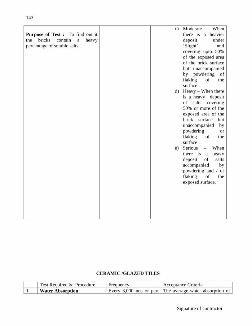
143
Signature of contractor
Purpose of Test : To find out it
the bricks contain a heavy
percentage of soluble salts .
c) Moderate – When
there is a heavier
deposit under
„Slight‟ and
covering upto 50%
of the exposed area
of the brick surface
but unaccompanied
by powdering of
flaking of the
surface .
d) Heavy – When there
is a heavy deposit
of salts covering
50% or more of the
exposed area of the
brick surface but
unaccompanied by
powdering or
flaking of the
surface .
e) Serious – When
there is a heavy
deposit of salts
accompanied by
powdering and / or
flaking of the
exposed surface.
CERAMIC /GLAZED TILES
Test Required & Procedure Frequency Acceptance Criteria
1 Water Absorption Every 3,000 nos or part The average water absorption of

144
Signature of contractor
Procedure – The tiles shall be
dried to constant weight at 110
± 5º C and then stored in a
desecrator until cooled to room
temp . The
Specimen shall be then weighed
(WD) in a balance to an
accuracy of 0.1 gm.
The weighed specimen shall
then be placed in distilled water
in a suitable Bessel and boiled
for two hours, during boiling
the test specimen shall
thereof . the tile when tested and
evaluated shall not exceed 18%
The water absorption of the
specimen shall be calculated as
follows :
Percentage Water Absorption :
WW-WD x 100/ WD
Where WW = Weight in gm of
the surface wiped specimen after
2 hours boiling in distilled water
and 20 hours immersion in cold
water.
be supported so as not to come in contact with the heated bottom of the container. After boiling the pieces shall be allowed to remain immersed in water for 20 hours, after which the excess water in the surface shall be removed by wiping the surface with a damp cloth and the specimen reweighed (WW) to an accuracy of 0.1 gm.
2. Crazing Test: Whole dry tiles
shall be subjected to crazing
test. They shall be placed
loosely at room temperature in
an autoclave which shall be of
sufficient capacity and
equipped with a safely valve,
blow off valve, thermometer,
pressure gauge and heating
arrangement.
Initially the blow-off valve shall be kept open until stream to escape thereby expelling most of the air. After closing the blow off valve, water shall be kept
Every 3,000 nos or part thereof.
After undergoing two cycles of the crazing test the tile shall not show any sign of erasing.

145
Signature of contractor
boiling and the steam pressure increased at uniform increased at uniform rate until it reaches 7.5 KGF / cm2 within a period of one and a half hour. Sufficient heat shall be applied to maintain a constant steam pressure of (7.5 + 0.2) KGF/ cm2 for one hour. The source of heat shall then be shut off and the steam pressure released slowly in not less than 30 minutes by opening the blow - off valve. The tiles shall be allowed to cool to room temperature in the autoclave. The Tiles shall
then be removed and tested for crazing by applying blue black fountain pen ink to the glazed surface.
3 Impact Strength Test Pendulum Apparatus Procedure- The tile shall be supported against three equally spaced steel pins in such a way that the pins are equidistant from the center of the tile shall be just touching the hammer when at the position of rest and the hammer shall always strike the tile of the center. With the preliminary adjustments complete, the tile shall be subjected to a series of impact of increasing energy until finally failure occurs. The initial blow shall be 0.002 KGF / m and each succeeding blow shall be increased in energy by increment of 0.001 k.g.f.m.
Every 3,000 nos or part thereof.
The impact strength value shall not be less than 0.02 kg.f.m. / cm. The impact strength of the specimen may be evaluated as follows: I = E/T Above I= Impact strength in k.f.g.m / cm E=Energy in K.g.f.m. T= Thickness of tile in cm.

146
Signature of contractor
The impact energy corresponding to the final failure of the tile shall be noted from the scale and the thickness of the tile shall be measured at the paint of impact.
Standard Size: 200 x 200, 300 x 300 or Tolerance in size: Facial dimension + 200 x 400. Thickness: 6.7 or 8mm. 0.25%, Thickness + 4%.
CEMENT CONCRETE TILES
(Conforming to IS 1237 - 1959)

147
Signature of contractor
Test Required & Procedure
Frequency Acceptance Criteria
1. a) 2
Transverse Strength
It shall be tested separately for the determination of dry and wet transverse strength. Dry Test: Full size tiles in the air dry state shall be used as a test specimen. The specimen shall be placed horizontally on bearers with its wearing surface upper most and its sides parallel to the bearers. The load shall be applied at mid-span by means of steel bar parallel to the bearers. The length of the bearer and of the loading bar shall be longer than the width of the tile and their contact faces shall be rounded to a dia meter of 25mm. A Plywood packing 3 mm thick and 25mm wide shall be placed between the tile and the bearers and between tile and loading bar. The loading bar and one of the bearers shall be self aligning. Starting from zero, the load shall be, increased steadily and uniformly at the rate not exceeding 200 kg / m of width per minute up to the specified maximum load which shall be maintained for at least 1.0 minute. Abrasion Test: To check resistance to wear.
6 tiles from a lot of 50,000 tiles or part thereof for each test. A set of 6 tiles for every 50,000 nos or on part thereof.
The average breaking look applied at mid span shall not be less than the following value. Breaking loads for transverse strength test on cement concrete flooring tiles.
Size of Tile Span
Breaking load (kp
kgs)
Wet
Test
Dry
Test
119.85*19.85 224.85*24.85 329.85* 29.85
15cm 20cm 25cm
71 80 99
106 120 149
Procedure: The test specimen shall be square in
A set of 6 tiles for

148
Signature of contractor
shape and of size 7.06 x 7.06 cm. The surface to be tested shall be ground smooth and filling removed. Measuring Instrument: A suitable instrument capable of measurement of accuracy of 0.01 mm shall be used for determining the change in the thickness of the specimen. Procedure: The specimen shall be derived of 1100C for 24 hrs and then weighed to the nearest 0.10 gm. The specimen after initial drying and weighing shall be placed in the thickness measuring apparatus, with its wearing surface upper most, the reading of the instrument is taken.
Water absorption
Preparation of specimen: Full size tiles shall be used for this test. They shall be immersed in water for 24 hrs then taken out, wiped dry and tested for water absorption. Procedure: Each tile shall be weighed immediately after saturation and wiping. The tile shall then be oven dried at a temp of 650C for a period of 24 hrs cooled to room temp and reweighed.
every 50,000 tiles or part thereof.
The average wear shall not exceed 2mm and the wear on any individual specimen shall not exceed 2.5mm. Determination of wear: The wear shall be determined from the difference in reading obtained by the measuring instrument before and after the abrasion of the specimen. The value shall be checked up with the average loss. In thickness of the specimen obtained by the following formula. T= 10 x (w1 - w2) x v1 / w1 x A T= Average loss in thickness in mm W1= Initial weight in gms W2= Final weight in gms V1= Initial volume in CC A= Surface area in sq.cm Determination of, water absorption Water absorption Percent by weight (on oven dry basis)= (w1-w2) x 100 /w2 where: w1= weight in gms of the specimen w2= weight in gms of the oven dried specimen The average water absorption shall not exceed 10%.

149
Signature of contractor
TIMBER
(Conforming to IS: 1708 – 1969)
Test Required & Procedure
Frequency Acceptance Criteria
1. a) b) c)
Moisture Content and Specific Gravity Test: Preparation and procedure Measurement and weight: Prior to each test the dimensions of each test the dimensions of each specimen shall be measured correct to 0.01 cm and the specimen shall be weighed correct to 0.001 gm. Control of moisture Content: Before the preparation of the test specimens for testing in the seasoned condition, the material shall be brought practically to constant weight by storage under controlled conditions at 270C + 20C temperature and 65 + 5% relative humidity. This is expected to bring the moisture content at 12% but if it is not exactly 12% it is permitted to test in the neighborhood of 12% and results shall be adjusted to 12% moisture content. The test shall be made under such conditions that large changes in moisture content do not occur.
For every ten cum or part thereof.
The loss in weight expressed as percentage of the oven dry weight shall be taken as the moisture content of the specimen. The formula for calculation shall be as given below: Percentage moisture contents = W1- WO / WO x 100 W1 = Weight of sample at test in gms. WO= Oven dry wt, of sample in gms. Moisture content shall not exceed following valued. i) Timber for frames = 14% ii) Timber for planking = 12% shutters etc.

150
Signature of contractor
d)
Control of Temperature: To avoid significant changes in strength properties all test specimen shall be tested within the temperature range of 270 + 20C. The temperature at the time of test shall be recorded. Rate of Loading: The rate of loading of the rest machine used shall not vary by more than + 20% from the specified speed for a given test. The load shall be applied continuously without interruption of the required speed throughout the test. The approximate percentage of sapwood if any, by volume,
Is estimated for all the test specimens and recorded. The number of the growth rings for 3 cm length shall be counted in the radial direction on each of the cross- section of such piece and the average shall be recorded as number of rings / cms for each specimen tested. Immediately after each mechanical test, disc approx 2.5cm in length and of full section as the test piece, shall be taken normally at the place of failure, failing which, at the central portion of the test specimen. In the case of shear test, the detached portion of the section approximately 5 x 5cm shall be taken for determination of moisture
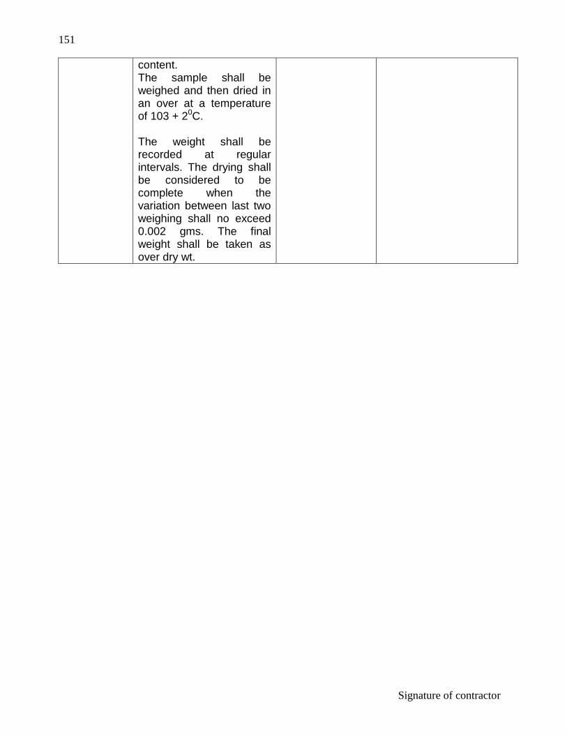
151
Signature of contractor
content. The sample shall be weighed and then dried in an over at a temperature of 103 + 20C. The weight shall be recorded at regular intervals. The drying shall be considered to be complete when the variation between last two weighing shall no exceed 0.002 gms. The final weight shall be taken as over dry wt.

152
Signature of contractor
CANCELED PAGE

153
Signature of contractor
WOODEN PANEL DOOR SHUTTERS
(Conforming to IS 2202 (Part I) 1983)
Test Required & Procedure Frequency Acceptance Criteria
1. 2.
Physical Test: Physical Verification- i) Name of the manufacturer or trade mark. ii) Thickness of door shutter. iii) Whether ISI Certification mark exists. Glue Adhesion Test: Procedure: Two square sections, 150 mm x 150mm shall be cut from the corners of the door. These corners sections, as out form the door, shall be Immersed in boiling water at 1000C for four hours, then dried at a temperature of 2700 + 200C and relative humidity of 65 + 5% for 24 hours. At the end of the drying period the samples shall be examined for delamination. Glue lines in all the four exposed edges of the plywood on both faces of a specimen and the glue lines between the plywood faces and the stile and rail shall be examined for delamination.
One from each lot.
A specimen shall be considered to have passed the test if no delamination has occurred in the glue lines in the plywood and if, no single delamination. More than 50mm in length and more than 3mm in depth has occurred in the assembly glue line between the plywood faces and the stile and rail.

154
Signature of contractor
READY MIXED PAINTS
Test Required & Procedure Frequency Acceptance Criteria
1.
Drive Time- Procedure: The material shall be brushed or sprayed as required on a 150 x 150mm mild steel panel prepared and allowed to air dry or stored under specified drying conditions. The material shall be examined after specified intervals, for the following conditions. i) Surface dry ii) Hard dry iii) Tack free: The procedure of test on the dried film of the panel after specified period as follows: Place the panel in one pan of a suitable balance and counterpoise it with weights. Place a further weight of 2.25 kg and press on the dried film surface of the panel with the thumb till the two pans are balanced. Hold for one minute and then slowly release. No sign of stickiness to the thumb shall be apparent and the thumb impression, if produced, shall be such as
On test each lot. (All containers of same size and same batch of manufacture constitute a lot).
No sign of stickiness to the thumb shall be apparent. The material shall not be cake hard inside the container and

155
Signature of contractor
2.
can be wiped away with dry cotton wool. Consistency:
shall be in such a condition that
3. 4.
Procedure: Insert a clean metal rod of palette knife into the original container and examine the nature of the setting.
Finish
Procedure: The material, when applied on an mild steel panel by brushing or spraying, whichever is specified to give a dry film weight commensurate with the weight per 10 lites of the material and allowed to dry in a vertical position under specified conditions, shall dry to hard, firmly adherent, flexible and smooth film free from sagging and wrinkling with a matt, semi-glossy or glossy surface in accordance with the requirement of the material specification.
Residue on Sieve
Outline: The material is mixed with a suitable solvent and passed through a 63 micron IS sieve. Not less than 20 gms of the material taken from under the tope skin shall be tested. Procedure: Accurately weigh the required quantity of the material and transfer to a 250 ml breaker using either 20ml of petroleum (Conforming to IS: 1745-1961) or 20ml of a
stirring easily produces a smooth uniform paint suitable for application. The film produced shall be of normal capacity and in no way interior to a film prepared in the same manner and at the same time from the approved sample, when examined not earlier than 46 hours and not later than 100 hours after application. In case of failure, the test shall be repeated by keeping the painted panel under standard atmospheric condition.

156
Signature of contractor
mixture containing equal parts by volume of petroleum hydrocarbon solvent and benzene. Wet a 63 micron IS sieve on both sides with solvent. Mix the material and the solvent in the breaker thoroughly, breaking up all lumps without grinding action, with the flattened end of a stirring rod.
5.
Transfer the contents of the breaker to the sieve using a wash bottle containing the solvent. Remove with the camel-hair brush any small pasficles of pigment that may be retained on the stirring rod or the walls of the breaker. Wash the residue left on the sieve with the sofuent and gently brush with a camel-hair brush until the solvent passing through the sieve is clear and free from solid particles. When the washing is complete, dry the sieve for one hour at 100 + 20C. Cool and transfer the residue with the help of the camel-hair brush to a weighed which glass and determine the weight of the residue.
Water Content
Outline of the method: The materials is heated under the reflex with on organic solvent which is immiscible with water. The carrier liquid distils into a graduated receiver carrying with it water which then separates to form the

157
Signature of contractor
lower layer, the excess carrier liquid overflowing from the trap and returning to the still. Procedure: Weigh 100 g of the material in the flask, add 100ml of dry petroleum hydrocarbon solvent (boiling point 75 to 850C) and IMI of dry ethyacetate (conforming to IS 229- 1964) or acetate (conforming to IS: 231-1957) and thoroughly mix the contents of the flask: Pour petroleum hydrocarbon solvent into the receiver up to the level of the side tube. Attach the flask to Dean and Stark condensing and collecting system and heat the flask at such a rate that the condensate falls from the end of the condenser at a rate of two to five drops per second.
6.
Continue the distillation until condensed water is no longer visible in any part of the apparatus except at the bottom of the graduated tube and until the volume of water collected remains constant. Remove the persistent ring of condensed water in the condenser tube, if any by increasing the rate of distillation by a few drops per second.
Weight per Litre
Outline of the Method: The calibated cylinder of CNP is filled with the material and weighed.

158
Signature of contractor
7.
Procedure: Weigh the cylinder or cup when empty and then fill to the brim with the material. Assuming that the volume of the content is 50 ml or 100 ml calculate and express as kg per 10 litres.
Lead Restriction
Outline of the method: Determination of lead in lead restricted paints is carried out by precipitating the lead as sulphide from the separated pigment, which is finally oxidized to lead monoxide. Procedure: Shake about one gram of the ground pigment obtained, accurately weighed, continuously for one hour at room temperature with 1000 times its weight of a aqueous solution of hydrochloric acid containing 0.25 percent by weight of hydrogen chloride.
Allow the mixture to stand for one hour and the fitter. Precipitate the lead salf contained in the clear filtrate as lead sulphide, fitter, that the lead sulphide, in air to convent it into lead sulphide, weigh calculate as lead monoxide (pbo) and express the result as percentage on the dry weight of the material taken for test.
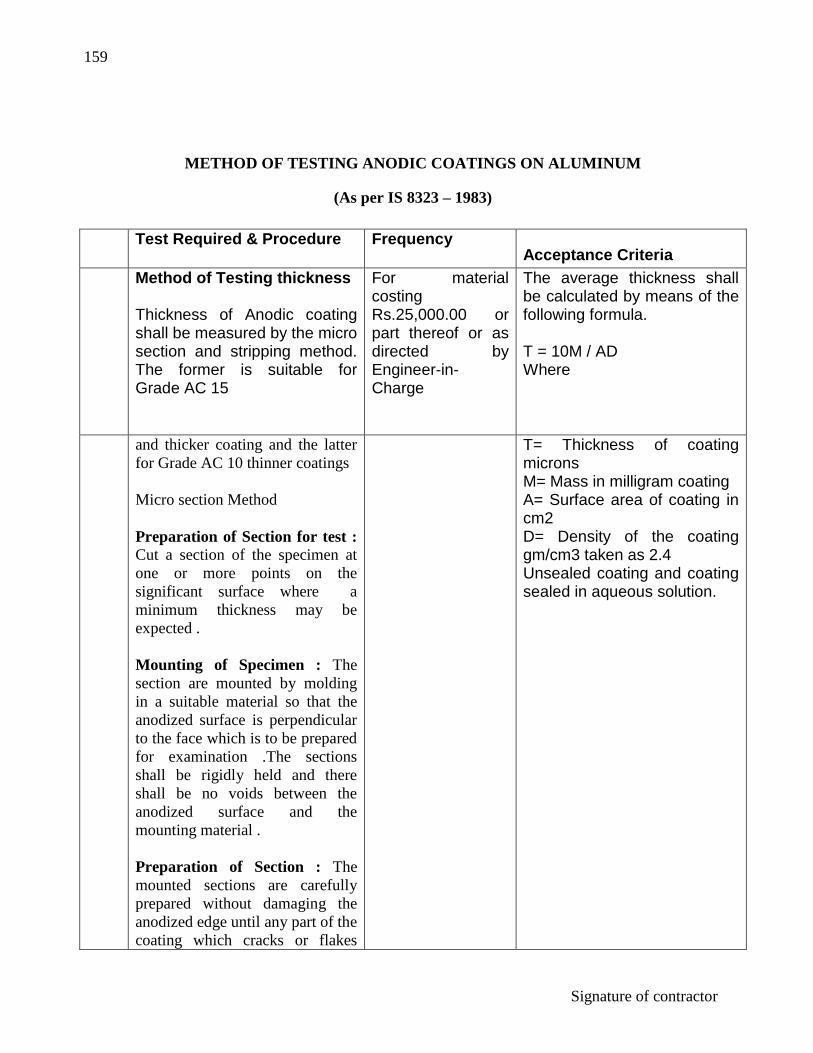
159
Signature of contractor
METHOD OF TESTING ANODIC COATINGS ON ALUMINUM
(As per IS 8323 – 1983)
Test Required & Procedure Frequency Acceptance Criteria
Method of Testing thickness Thickness of Anodic coating shall be measured by the micro section and stripping method. The former is suitable for Grade AC 15
For material costing Rs.25,000.00 or part thereof or as directed by Engineer-in-Charge
The average thickness shall be calculated by means of the following formula. T = 10M / AD Where
and thicker coating and the latter
for Grade AC 10 thinner coatings
Micro section Method
Preparation of Section for test :
Cut a section of the specimen at
one or more points on the
significant surface where a
minimum thickness may be
expected .
Mounting of Specimen : The
section are mounted by molding
in a suitable material so that the
anodized surface is perpendicular
to the face which is to be prepared
for examination .The sections
shall be rigidly held and there
shall be no voids between the
anodized surface and the
mounting material .
Preparation of Section : The
mounted sections are carefully
prepared without damaging the
anodized edge until any part of the
coating which cracks or flakes
T= Thickness of coating microns M= Mass in milligram coating A= Surface area of coating in cm2 D= Density of the coating gm/cm3 taken as 2.4 Unsealed coating and coating sealed in aqueous solution.

160
Signature of contractor
during the cutting process is
removed .
The surface may lightly etched to
improve the contact between the
coating and the adjacent metal and
to remove any soft metal which
may have spread over the coating
.
Measurement of Thickness of
Coating :
Measure the thickness of coating
at any desired point on the
exposed section by following
methods.
Measure the thickness with a filler
micrometer ocular that has been
calibrated in orders to determine
the value of the unit scale division
against a scale graduated so
accurately that error will not
exceed 2%
For purpose of reference . 5
measurement shall be made at
point evenly spaced over the
entire significant surface of the
sample.
Stripping method
This method is subject to errors
when used on coating which are
heavily pigmented or sealed with
organic material .
Applicability : This method is
mainly applicable to grade AC 10
and thinner coatings .
Preparation of Test Piece : The
sample would be of a shape whose
surface area is readily determined
and this area would be within the
range 8 to 100 cm² and mass of
For material costing Rs. 25,000.00 or part thereof if required by Engg.-In-Charge.

161
Signature of contractor
the sample shall not exceed 100
gms .
Stripping solution : The stripping
solution shall consist of a solution
in distilled water of
Phosphoric Acid ( RD = 1.75 ) 3.5
percent (v/v)
Chromic Acid (AR quality ) – 2.0
percent (M/V)
The solution should be contained
in a glass breaker .
Procedure : Weigh the clean and
dry anodized test piece to the
nearest milligram and immerse in
The boiling stripping solution
taking care that it is not in contact
with any other metal . Wash the
test piece in hot distilled water .
Dry and re – weigh . Repeat the
process until reasonably constant
mass is obtained . Normally total
time of immersion may not last
for more than 10 minutes .
The loss in mass shall be taken as
the mass of the anodic coating .

162
Signature of contractor
STATEMENT SHOWING QUANTITIES OF THEORETICAL
CONSUMPTION OF CMENT FOR MAJOR ITEM OF WORK
(AS PER CPWD NORMS)
Sl.
No.
Description of item of work Unit Quantity of
1 2 3 4
1
2
3
4
Plain Cement Concrete Work
a) Cement concrete ( 1:2:4)
b) Cement concrete (1:3:6)
c) Cement concrete (1:4:8)
d) Cement concrete (1:5:10)
Damp Proof Course
a) 25 mm thick in C.C (1:2:4)
b) 38 mm thick in C.C (1:2:4)
c) 50 mm thick in C.C (1:2:4)
Reinforced Cement Concrete Work
a) RCC work in C.C (1:2:4)
b) RCC work in C.C(1:1½:4)
c) RCC work in C.C (1:1:2)
d) Providing and fixing precast RCC
mortar 1:2 including finishing with
cement plaster 1:3 of thickness not
exceeding 6 mm.
i) Kerb , step and the like
ii) Coping bed plates anchor
blocks, window sills and the
like
iii) Small lintels not exceeding 1.5
mm clear, coping shelves and
the like.
a) Brick work (all classes ) in cement
mortal 1:3
i) With modular brick
ii) With F.P.S brick
b) Brick work (all classes ) in
cement mortar 1:4
Cum
Cum
Cum
Cum
100 Sqm
100 Sqm
100 Sqm
Cum
Cum
Cum
Cum
Cum
Cum
Cum
Cum
3.20
2.20
1.70
1.30
8.00
12.16
16.00
3.20
4.00
6.10
3.68
3.86
3.90
1.12
1.28

163
Signature of contractor
i) With modular brick
ii) With F.P.S brick
c) Brick work (all classes ) in cement
mortar (1:5)
i) With modular brick
ii) With F.P.S brick
d) Brick work (all classed ) in cement
mortar (1:6)
i) With modular brick
ii) With F.P.S bricks
e) Half brick ( all classes ) in cement
mortar (1:3 )
i) With modular brick
ii) With F.P.S brick
f) Half brick (all classes ) in cement
mortar ( 1:4 )
i) With modular brick
ii) With F.P.S bricks
g) Brick work 3” in cement mortar 1:3
with FPS brick
h) Honey comb brick work half brick
thick in cement mortar (1:4)
i) With modular brick
iii) With F.P.S brick
I) Brick drip course at junction of
roofs and walls in cement mortar
(1:4)
i) 10 cm thick with modular brick
ii) 7.6 cm thick with F.P.S brick
j) Brick drip course at junctions of
roofs and walls in cement mortar (
1:6)
i) 10 cm thick with modular brick
ii) 7.6 cm thick with F.P.S brick
k) Providing brick band 5 cm
projected from wall face in cm
(1:4)
Cum
Cum
Cum
Cum
Cum
Cum
100 Sqm
100 Sqm
100 Sqm
100 Sqm
100 Sqm
100 Sqm
100 Sqm
100 m
100m
100 m
100 m
0.84
0.95
0.68
0.78
0.55
0.62
12.75
14.28
09.50
10.64
9.23
05.54
06.56
0.84
0.83
0.55
0.54

164
Signature of contractor
5
i) 10 cm thick 5 cm projected
with modular brick
ii) 7.5 thick 5.7 cm projected with
FPS brick
Stone work
a) Random ruble masonry within
foundations or super structure in
cement mortar 1:6 including
leveling up with cement concrete
1:6:12 at plinth or sill o ceiling
level.
b) Coursed rubble masonry in
foundation and superstructure in
cement mortar 1:6
c) Stone work plain ashlars
cyclopean, sunk or mounded and
ashlarpunched in cement mortar
1:6 including pointing with an
admixture of pigment matching
the stone shade.
d) Stone work in plain ashlars
cyclopean sunk or mounded arch,
dome or circular mounded and
curve columns in cement mortar
1:3 including painting with
cement mortar 1:2 with an
admixture of pigment matching
the stone shade.
e) Stone work in plain in coping
cornices, string courses and plinth
courses in cement mortar 1:6
including pointing with cement
mortar 1:2 with and admixture of
pigment matching the stone shade.
f) Stone work for wall lining etc
average thickness 40 mm to 70
mm in cement mortar 1:3
including pointing with cement
mortar 1: 2 with an admixture of
pigment matching the stone shade.
100 m
100 m
Cum
Cum
Cum
Cum
Cum
100 Sqm
0.42
0.41
0.85
0.75
0.54
1.07
0.54
8.75

165
Signature of contractor
6
g) Stone work for wall lining etc
average thickness 40 mm to 70
mm in cement mortar 1:3
including pointing with cement
mortar 1: 2 with an admixture of
pigment matching the stone shade.
Flooring
a) Brick flooring in cement mortar
1:4
b) Brick flooring in cement mortar
1:6
c) 25mm thick cement concrete
flooring 1:2:4 finished with a
floating coat of neat cement.
d) 40mm thick cement concrete
flooring 1:2:4 finished with a
floating coat of neat cement.
e) 40mm thick cement concrete
flooring 1:2:4 finished with a
floating coat of neat cement
f) 75mm thick cement concrete
flooring 1:2:4 finished with a
floating coat of neat cement.
g) Cement concrete pavement (25mm
to 50mm thick) with 1:2:4
including finished complete.
h) 50mm thick cement concrete
flooring with metallic flooring
hardener topping, under layer of
40mm thick cement concrete 1:2:4
and top layer 10mm thick metallic
cement hardener consisting of mix
1:2 by volume with metallic
hardening compound of approved
quality is mixed in the ratio of 4:1
i) 40mm thick cast in situ mm
flooring (28mm thick under layer
and 12mm thick top layer)
i) Neutral shade with cement with
Grey cement
ii) Light shade with white cement
(Grey cement)
100 Sqm
100 Sqm
100 Sqm
100 Sqm
100 Sqm
100 Sqm
100 Sqm
100 Sqm
100 Sqm
100 Sqm
1.64
11.02
7.25
10.20
15.00
18.20
26.20
03.20
21.10
01.95
04.05
10.90

166
Signature of contractor
iii) Medium shaded 50% Grey
Cement (white cement)
j) Precast terrazzo tiles 20mm thick
with marble chips of sizes up to
6mm laid in 25mm thick bed of
lime mortar jointed with neat
cement slurry mixed with pigment.
i) Light shade using white cement
Grey Cement
ii) Medium shade using 50% white
cement, 50% grey cement
White cement Grey Cement
iii) Neutral shades (with grey cement)
k) Precast terrazzo tiles 20mm thick
with marble chips of sizes upto
6mm in skirting or on walls, laid on
12mm thick cement plaster (1:3)
jointed with neat cement slurry
100 Sqm
100 Sqm
100 Sqm
100 Sqm
12.92
02.02
04.40
02.20
06.60
08.80
i)
Light shade using White cement Grey Cement. ii) Medium shade using 50% white cement & 50% grey cement white cement Grey cement. iii) Neutral shades (With grey cement)
100 Sqm
100 Sqm
02.20 11.24
01.10 12.84
13.94
l) Chequered terrazzo tiles 22 mm thick with marble chip of sizes up to 6mm on 25mm thick

167
Signature of contractor
bed of lime mortar jointed with neat cement slurry. i) Light shade using 50% white cement Grey cement. ii) Medium Cement Grey Cement. iii) Neutral shades (with grey cement)
100 Sqm
100 Sqm
100 Sqm
04.40 04.40
02.20 06.60
08.80
m) White glazed tiles 5.5mm thick in flooring treads and risers of steps skirting and dado on 12mm thick cement plaster 1.3 in base and jointed with white cement slurry etc. White cement Grey cement
100 Sqm
100 Sqm
02.50
10.44
n) Marble stone slab flooring over 20mm thick base line mortar and jointed with grey cement slurry etc. i) 25mm thick ii) 30mm thick iii) 40mm thick
100 Sqm 100 Sqm 100 Sqm
05.00 05.12 05.36
o) Marble stone slab flooring over 20mm thick base of cement mortar (1:4 and jointed with grey cement slurry) i) 25mm thick ii) 30mm thick iii) 40mm thick
100 Sqm 100 Sqm 100 Sqm
13.51 13.63 13.87
p) Extra if while cement slurry used instead of grey cement slurry in joints of stone flooring white cement.
100 Sqm 0.76
q) Marble tiles 25mm thick in risers of steps, skirting and pillars, laid on 12mm thick cement mortar (1:3) and jointed with grey cement slurry etc.
100 Sqm 12.34

168
Signature of contractor
r) Kota stone slab flooring over 20mm thick base of lime mortar and jointed with cement slurry etc. i) 25mm thick. ii) 30mm thick iii) 40mm thick
100 Sqm 100 Sqm 100 Sqm
3.40 6.80 7.60
s) Kota stone slab flooring over 20mm thick base of cement mortar (1:4) and joint with neat cement slurry etc. i) 25mm thick ii) 30mm thick iii) 40mm thick
100 Sqm 100 Sqm 100 Sqm
14.91 15.31 16.11
t) Kota stones slab 25mm thick in rise of steps skirting dado and pillars laid on 12mm thick cement mortar 1:3 and jointed with neat cement slurry etc.
100 Sqm 13.74
u) 40mm sand thick sand stone flooring over 20mm thick base of cement mortar 1:5 with joints finished flush.
100 Sqm 7.75
v) 40mm thick sand stone flooring over 20mm thick base of cement mortar 1:5 including pointing with cement mortar 1:2 (1 cement : 2 stone dado).
100 Sqm 9.31
w) 40mm thick sand stone flooring over 20mm thick lime mortar including pointing with cement mortar 1:2.
100 Sqm 1.56
x) 40mm thick fine dressed and rubbed stone, flooring over 20mm thick base of cement mortar 1:5 (1 cement : 5 sand) with joints 0 mm thick finished flush.
100 Sqm 8.28
y) 40mm thick fine dressed and rubbed stone, flooring over 20mm thick base of cement mortar 1:5 with joints 5mm thick including pointing with cement mortar 1:2 (1 cement : 2 stone dust).
100 Sqm 9.84

169
Signature of contractor
7. Finishing
a) 12mm cement plaster 1:3
100 Sqm 7.34
b) 12mm cement plaster 1:4
100 Sqm 5.47
c) 12mm cement plaster 1:5
100 Sqm 4.46
d) 12mm cement plaster 1:6
100 Sqm 3.60
e) 15mm cement plaster 1:3
100 Sqm 8.77
f) 15mm cement plaster 1:4
100 Sqm 6.54
g) 15mm cement plaster 1:5
100 Sqm 5.33
h) 15mm cement plaster 1:6
100 Sqm 4.30
i) 20mm cement plaster 1:3
100 Sqm 11.42
j) 20mm cement plaster 1:4
100 Sqm 8.51
k) 6mm cement plaster to ceiling 1:3
100 Sqm 3.67
l) 6mm cement plaster to ceiling 1:4
100 Sqm 2.34
m) Neat cement punning
100 Sqm 2.20
n) 18mm cement plaster in two coats under layer 12mm cement plaster 1:5 finished with a top layer 6mm thick with cement plaster 1:6.
100 Sqm 6.26
o) 18mm thick cement plaster in two coats under layer 12mm thick cement plaster 1:5 and top layer 6 mm thick with cement plaster 1:3.
100 Sqm 6.26
p) 12mm cement plaster 1:2 (1 cement : 2 stone dust).
100 Sqm 8.13

170
Signature of contractor
q) 18mm thick or artificial red stone plaster of 12mm thick under layer of cement plaster 1:4 with 6mm thick finishing coat of cement mortar 1:1:3 mixed with red oxide (1 cement : 1 marble dust : 3 stone dust).
100 Sqm 9.47
8. Pointing
a) Flushed or ruled or cut or weather pointing or brick work with cement mortar 1:3.
100 Sqm 1.53
b) Raised and cut pointing on brick work with cement mortar 1:3.
100 Sqm 2.35
c) Flush or ruled pointing on stone work with cement mortar 1:3.
100 Sqm 1.17
d) Raised and cut pointing on stone work with cement mortar 1:3.
100 Sqm 1.94
9. Mortar
a) Cement mortar 1:1
Cum 10.20
b) Cement mortar 1:2
Cum 6.80
c) Cement mortar 1:3
Cum 5.10
d) Cement mortar 1:4
Cum 3.80
e) Cement mortar 1:5
Cum 3.10
f) Cement mortar 1:6
Cum 2.50
10. Miscellaneous
a) Lime concrete terracing average 10cm thick with 25mm brick ballast and 50% lime
100 Sqm 6.63

171
Signature of contractor
concrete 1:2 (1 lime putty: 2 surkhi) rammed and finished with gur and belgri treatment and covered with flash brick tiles grouted with cement mortar 1:3 over 12mm layer of cement mortar 1:3.
b) Providing and laying average 10 cm thick cement based water proofing treatment with brick bat coba as per manufacturers specification.
100 Sqm
c) Providing and filling with water proof bat cement concrete.
Cum
d) Rough cast or pebble dash plaster in two layers under layer 12mm cement plaster 1:4 and top layer 10mm cement plaster 1:3.
100 Sqm 10.58
e) Plinth protection 50mm thick in cement concrete 1:3:6 over 75 mm bed of dry brick ballast.
100 Sqm 11.00
f) Brick edging 10cm wide 10cm deep to plinth protection including grouting with cement mortar (1:4).
100 Sqm
g) Fixing of pre-cast cement concrete jail 1:2:4 in cement mortar 1:3.
i) 50mm thick
100 Sqm 1.64
ii) 40mm thick
iii) 25mm thick
As specified by the specialist firm at the time of tendering for the job.

172
Signature of contractor
Note:- For any other item of work Site Engineer shall refer to the C.P.W.D. Specifications and norms.
LIST OF MATERIALS OF APPROVED MAKES/BRAND
(CIVIL WORKS)
The contractor shall use materials in their works subject to inspection prior to dispatch, by Owner or his
authorized representative of any materials, as deemed necessary in accordance with the following list. All
materials not otherwise specified shall be in accordance with the latest Indian Standard Specification, where
such exists and subject to prior approval of Owner / Architect. Contractor shall be bound to supply items of any
make of the items as per the choice of the Owner / Architect.
1. Plastered walls and False ceiling etc. – Premium Quality Plastic Emulsion Paints of J&N Instacolor /
Nerolac / ICI /Asian / Berger
2. Enamel Paint:- J&N Instacolor / Nerolac / ICI / Asian / Berger
3. Textured Paint:- Hatch Lamina / Spectrum / Approved Equivalent.
4 12, 8 mm thick plate glass / float glass – MODIGUARD / AIS
5. Float Glass – MODIGUARD / AIS
6. Bathroom Mirror – GOLDEN FISH / TWIN BRID / ATUL / MODIGUARD / AIS of Float Glass.
7. Ceramic Tiles – KAJARIA / SPARTEK / SOMANY / PEDDER (Grade IV minimum hardness)
8. Aluminium sections INDAL / JINDAL / HINDALCO
9. Vitrified Tiles - JOHNSON / ASIAN / MAX / SOMANY / KAJARIA / MARBITO
10. Steel – TATA-TISCON / SAIL / RINL / CAPTAIN / GISCO
11. Cement- Lafarge / Ultratech / ACC / Jaypee
NOTE:- The Architect / Employer shall have the final say about which makes amongst the ones
mentioned shall be used in the project and the contractor shall have no claims on this amount.
For any items for which the makes are not specified, the decision of the Architect / Employer
shall be final & binding.
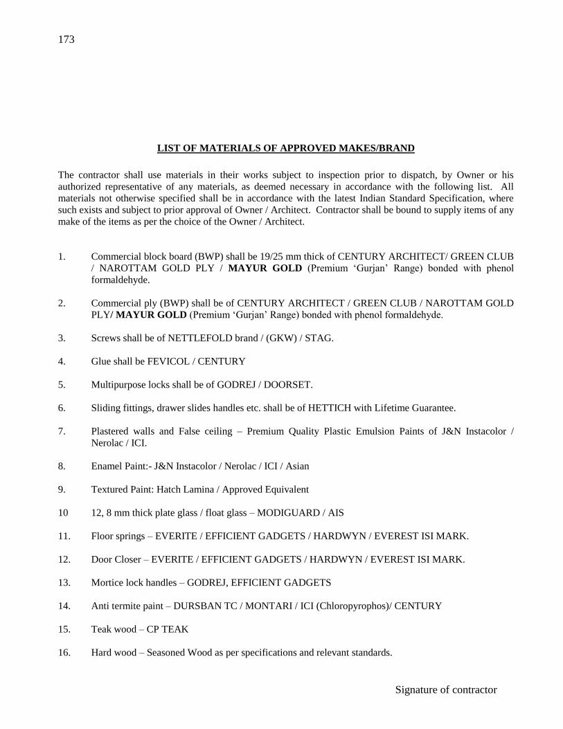
173
Signature of contractor
LIST OF MATERIALS OF APPROVED MAKES/BRAND
The contractor shall use materials in their works subject to inspection prior to dispatch, by Owner or his
authorized representative of any materials, as deemed necessary in accordance with the following list. All
materials not otherwise specified shall be in accordance with the latest Indian Standard Specification, where
such exists and subject to prior approval of Owner / Architect. Contractor shall be bound to supply items of any
make of the items as per the choice of the Owner / Architect.
1. Commercial block board (BWP) shall be 19/25 mm thick of CENTURY ARCHITECT/ GREEN CLUB
/ NAROTTAM GOLD PLY / MAYUR GOLD (Premium „Gurjan‟ Range) bonded with phenol
formaldehyde.
2. Commercial ply (BWP) shall be of CENTURY ARCHITECT / GREEN CLUB / NAROTTAM GOLD
PLY/ MAYUR GOLD (Premium „Gurjan‟ Range) bonded with phenol formaldehyde.
3. Screws shall be of NETTLEFOLD brand / (GKW) / STAG.
4. Glue shall be FEVICOL / CENTURY
5. Multipurpose locks shall be of GODREJ / DOORSET.
6. Sliding fittings, drawer slides handles etc. shall be of HETTICH with Lifetime Guarantee.
7. Plastered walls and False ceiling – Premium Quality Plastic Emulsion Paints of J&N Instacolor /
Nerolac / ICI.
8. Enamel Paint:- J&N Instacolor / Nerolac / ICI / Asian
9. Textured Paint: Hatch Lamina / Approved Equivalent
10 12, 8 mm thick plate glass / float glass – MODIGUARD / AIS
11. Floor springs – EVERITE / EFFICIENT GADGETS / HARDWYN / EVEREST ISI MARK.
12. Door Closer – EVERITE / EFFICIENT GADGETS / HARDWYN / EVEREST ISI MARK.
13. Mortice lock handles – GODREJ, EFFICIENT GADGETS
14. Anti termite paint – DURSBAN TC / MONTARI / ICI (Chloropyrophos)/ CENTURY
15. Teak wood – CP TEAK
16. Hard wood – Seasoned Wood as per specifications and relevant standards.
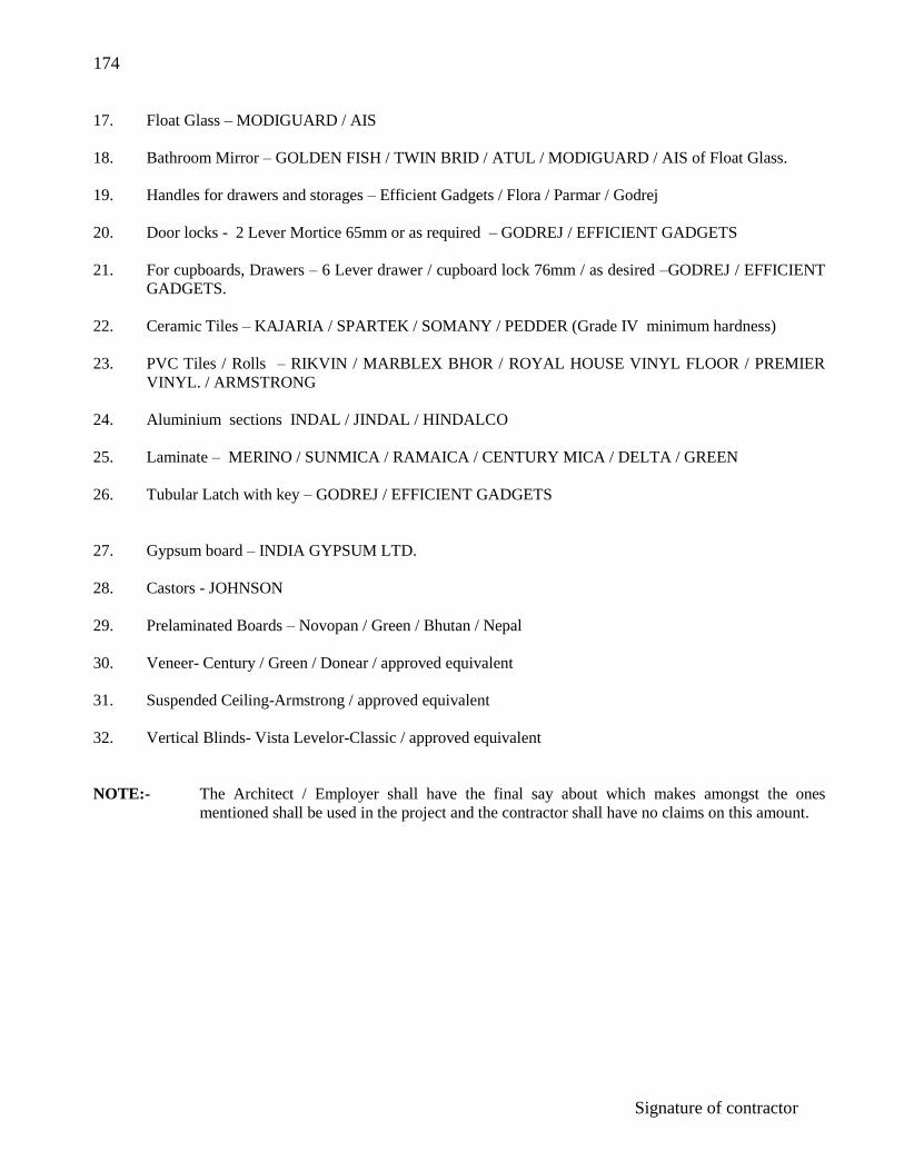
174
Signature of contractor
17. Float Glass – MODIGUARD / AIS
18. Bathroom Mirror – GOLDEN FISH / TWIN BRID / ATUL / MODIGUARD / AIS of Float Glass.
19. Handles for drawers and storages – Efficient Gadgets / Flora / Parmar / Godrej
20. Door locks - 2 Lever Mortice 65mm or as required – GODREJ / EFFICIENT GADGETS
21. For cupboards, Drawers – 6 Lever drawer / cupboard lock 76mm / as desired –GODREJ / EFFICIENT
GADGETS.
22. Ceramic Tiles – KAJARIA / SPARTEK / SOMANY / PEDDER (Grade IV minimum hardness)
23. PVC Tiles / Rolls – RIKVIN / MARBLEX BHOR / ROYAL HOUSE VINYL FLOOR / PREMIER
VINYL. / ARMSTRONG
24. Aluminium sections INDAL / JINDAL / HINDALCO
25. Laminate – MERINO / SUNMICA / RAMAICA / CENTURY MICA / DELTA / GREEN
26. Tubular Latch with key – GODREJ / EFFICIENT GADGETS
27. Gypsum board – INDIA GYPSUM LTD.
28. Castors - JOHNSON
29. Prelaminated Boards – Novopan / Green / Bhutan / Nepal
30. Veneer- Century / Green / Donear / approved equivalent
31. Suspended Ceiling-Armstrong / approved equivalent
32. Vertical Blinds- Vista Levelor-Classic / approved equivalent
NOTE:- The Architect / Employer shall have the final say about which makes amongst the ones
mentioned shall be used in the project and the contractor shall have no claims on this amount.

175
Signature of contractor
TECHNICAL SPECIFICATION FOR ELECTRICAL WIRING
1.0 GENERAL REQUIREMENTS
The installation shall generally be carried out in conforming with the requirements of the Indian
Electricity Act, 1910 as amended upto date and the Indian Electricity Rules, 1956 framed thereunder,
the relevant regulations of the Electric Supply Authority concerned, and also with the specifications laid
down in the Indian Standard I.S 732-1963 Code of Practice (revised) for Electrical Wiring Installations
(system voltage not exceeding 650 volts) and I.S 2309-1969 Code of Practice for the protection of
Buildings and Allied Structure against Lighting and IS 3043- Indian code of Practice for Earthing. The
wiring shall also be according to the I.S specifications, NEC, Local Government Body.
Only the contractor having valid Electrical Contractor Licence of state shall be eligible to execute the
same. The contractor shall be responsible for renewal of the same at the appropriate time.
2.0 MATERIALS
All materials, fittings, appliances, used in electrical installations, shall conform to Indian Standard
Specifications wherever these exist. A list of approved materials is attached afterwards. Materials not
included in the list shall be got approved by the Architects / Engineer-in-Charge/Owner prior to actual
use.
3.0 MAIN SWITCH GEAR
Iron clad switch fuse and isolator units should conform to relevant I.S.Standard. The quick make and
break mechanism shall be self interlocked with the cover. In “Off” position there must be two breaks
per pole.
Main switch gear shall be properly earthed with two numbers conductors if M.V and one number of
L.V.
4.0 BUSBAR CHAMBER (B.B.C)
This shall be totally enclosed, metal clad type fabricated from rust proofed 16 SWG sheet steel on angle
iron frame and provided with sheet steel or cast iron detachable front cover and undrilled detachable
end plates, suitable for mounting on wall or angle iron floor stand and painted with high quality enamel
paint G.I bolts and nuts shall be used for assembly with suitable packing materials to ensure dust proof
finish. Meters shall be provided on suitable sheet steel boxes. Switch shall be provided with cable end
boxes are required.
The depth of B.B.C shall be 250mm (minimum). Minimum clearance of phase bars to earth shall be
25mm and between bus bars shall be minimum 32mm.

176
Signature of contractor
H.C (High conductivity) copper busbars properly tinned are to be rated at 1000 Amps per sq. in and
Aluminium bus bars (wrought aluminium alloy strip) conforming to relevant I.S specification at 800
Amps per sq. in.
Neutral Busbars are to be rated to carry 100% of phase current upto 200A and 60% for higher. These
shall be mounted on DMC/SMC supports of proper diselectric and mechanical strength and shall be
appropriately colour coded for identification of Phase with PVC sleeves of 1.1 KV grade throughout the
length.
Lettering shall be done for identification of switches as directed. The contractor shall submit fully
dimensioned drawing of the board with the physical position of the switches and other components to
the Architects for their approval before the same is fabricated.
There shall be two nos of Earth Terminals. Suitable Danger Board shall be provided.
5.0 INTERCONNECTION IN B.B.C, SWITCH FUSE, METERS
For ratings above 150 Amps shall consist of insulated copper strips of adequate section considering
current density as specified in Cluase 4 above. For rating below 150 Amps PVC copper cable tails of
appropriate size, terminating in tinned copper sockets may be used considering 1.5 Amp/sq.mm for
aluminium. The above are to be enclosed either in sheet metal trunking or conduits so that no part is
exposed.
6.0 DISTRIBUTION BOARDS
These totally enclosed metal clad type Distribution Boards with hinged lids shall be in accordance with
I.S 2147-1952 and 2675-1966 and B.S 214 and shall be of welded construction and fabricated from rust
proofed sheet steel and finished with anticorrosive stove enamel paint and have provision for fixing on
wall and have earthing terminals / terminals.
Power Distribution Boards (400 volts TPN) shall be constructed from 16 SWG sheet steel and Branch
Distribution Boards (230 volts SPN from 18 SWG sheet steel).
The MCB shall be mounted on Din rails supports of proper dielectric & mechanical strength. If
fuses/fuse banks are used these shall be mounted on moulded DMC/SMC or ebonite supports of proper
dielectric and mechanical strength. TPN units should have phase separation barriers.
Cables shall be connected to a terminal by crimped lugs.
Where two or more B.D.B‟s feeding low voltage circuits are fed from different phases of a medium
voltage supply, these B.D.B‟s shall be installed atleast two metres apart or otherwise in a different
direction to prevent access to the both DBs at a time.
All three phase power distribution boards shall be properly earthed with two number 10 S.W.G
galvanized iron wires and provided with suitable Danger Board. All SPN B.D.B‟s shall be properly
earthed with one number 10 SWG galvanized iron wire each or with insulated copper PVC wire of
adequate ratings in case of concealed wiring as per the specifications.
7.0 SWITCHES
All switches for lights, fans and plug points shall be piano type switches, unless specified otherwise.

177
Signature of contractor
8.0 CABLES AND CONDUCTORS
All cables shall conform to IS-692, IS-7098, IS-1554 (Part-I) 1964 and IS 694-1990 or latest.
Conductors of all cables except for flexible cables, shall be aluminium, unless specified otherwise.
9.0 FLEXIBLE CABLES
Conductors of flexible cables shall be of copper. The minimum size of core acceptable is 1.50 sq.mm.
10.0 INSTALLATION OF MAIN SWITCH BOARD, BDB‟S MAINS, SUBMAINS, DISTRIBUTION
WIRING TO INDIVIDUAL POINTS
The exact positions of all main switch board, BDB‟s and all runs of mains and submains, and
distribution wirings to individual points including the exact position of all light fittings and switch
boards shall be first marked on the buildings and shall be approved by the Engineer-in-Charge before
actual commencement of the work.
The D.Bs shall generally be installed at a height of 2.13m (7 ft) from floor level.
11.0 INSTALLATION OF SWITCH BOARDS
These shall be installed at a height of 1.3 mtrs (4‟-3”) and above the floor level.
12.0 INSTALLATION OF CEILING FANS
Unless otherwise specified all ceiling fans shall be hung not less than 2.75M (9 ft) above floor. The
suspension and clamp shall be painted with approved paint without involving extra cost.
13.0 INSTALLATION OF FLUORESCENT LIGHT FITTINGS
Where these are suspended from ceiling by two down rods, or fixed to ceiling/beam directly, at least
one fixing to the ceiling/beam shall be made with Mechanical/Metal fasteners, Electrical drill only shall
be used while making holes for the fasteners which shall be capable of sustaining at least 15 kg of dead
weight.
The down rods and accessories shall be painted with approved paint without involving extra cost.
Unless otherwise specified these should be suspended 2.60M (8‟-6”) above the floor or as per direction
of Owner/Architect to match interiors.
14.0 INSTALLATION OF EXHAUST FANS
Exhaust Fans shall be fitted by means of rag bolts embedded or on suitable size block board (12mm
thick) in the wall./window panels. The required holes in the wall shall be made and finished neatly with
cement plaster and brought to the original finish of the wall. In case of block board mounting all fixing,
cutting shall be made by the electrical contractor in coordination with civil/interior decoration
contractor without extra cost.
15.0 INSTALLATION OF SOCKET OUTLETS

178
Signature of contractor
No socket outlet shall be provided in the bath room at the height less than 130 cms (4‟-3”) from the
floor.
No switches shall be provided inside the bath rooms, unless approved by the Engineer-in-Charge.
Socket outlet at location other than bath rooms shall be either 25 cms (10”) or 130 cms (4‟-3”) from the
floor.
16.0 INSTALLATION OF ELECTRIC MOTORS
Electric Motors shall be earthed either with 2 numbers SWG 6 G.I wires, if M.V and 1 number if L.V or
insulated copper PVC wires of adequate sizes as approved by Owner/Architects without any extra cost
to the Owner.
17.0 TESTING OF INSTALLATION
Before a completed installation or an addition to an existing installation is put into service, the
following tests shall be carried out by the contractor in presence of the Engineer-in-
Charge/Owner/Architects.
a) Polarity of switches
It must be ensured by test that all single pole switches have been fitted on the live side of the
circuits they control.
b) Insulation Test:
i) By applying a 500 volt megger between earth and the whole system of conductors or
any section thereof, with all fuses in place and all switches closed, all lamps in position
or both poles of installation otherwise electrically connected together:- The result in
meghom shall not be less than 50 divided by the number of points on the circuit, and
should not be less than 1 meghom.
ii) Between all conductors connected to one phase and all such conductors connected to
the neutral or to the other phase conductors of the supply after removing all metallic
connections between the two poles of the installation and switching on all switches.
The insulation resistance shall be as in (i) above.
c) Earth continuity Test
The earth continuity conductor including metal conduits and metal sheaths of cables in all cases
shall be tested for electrical continuity. Electrical resistant of the above along with the earthing
lead but excluding any resistance of earth leakage circuit breaker, measured from the
connection with the earth electrode to any point in the earth continuity conductor in the
completed installation shall not exceed one ohm.
d) Earth Resistance Test
To ensure effectiveness of installation earth, the value of earth resistance shall be within 5 ohm
for installation capacity upto 5 KW and one ohm for installation of higher capacity.

179
Signature of contractor
18.0 The completed work will be taken over only if the results obtained in above tests are within the limits
mentioned above, and in accordance with I.E. Rules.
On completion of the installation work, a certificate shall be furnished by the contractor, countersigned
by the certified supervisor under whose direct supervision the installation was carried out. This
certificate shall be in a prescribed form as required by the local Electric Supply Authority. The
installation shall not be considered as complete unless the installation is got inspected and passed by the
Electrical Inspector, Directorate of Electrical Safety, of the local State Govt/Authority. The contractor
shall have to take all initiatives and follow up the matter at his own cost for early approval of the
installation for permanent energisation of the installation from the Directorate of Electrical Safety, of
the local State Govt/Authority. No extra amount will be paid on this account. However statutory fees,
if any, will be reimbursed to the contractor on production of documentary evidences/official money
receipts.
19.0 SPECIAL SPECIFICATIONS
a) Before fixing all switches, fittings etc. these should be produced before Engineer-in-charge and
get approved.
b) All metal switch boards and switch/regulator boxes to be used in work shall be painted with
two coats of anti rust primer (red oxide paint) prior to erection. After erection these shall be
again painted with two coats of enamel paint of approved quality and shade.
c) Before execution of any portion of conduit work for wiring a neat proper layout should be made
out by the contractor and got approved from the Engineer-in-Charge. For this purpose
contractor is advised to get acquinted with the layout drawings of the Consultant / Architect /
Electrical Contractor.
d) While laying the conduits for concealed wiring in the ceiling / beams / columns / walls /
partitions / modular furniture etc, the contractor must ensure that all the inlets and both ends of
the conduits are plugged to stop entry of foreign materials so that no difficulty arises during
drawing of wires later.
e) Damage to any fitting during erection and before handing over the installation by contractor
shall be set right or replaced by the contractor at his own cost.
f) Caution Board of proper size wherever required, shall be provided, as per I.E.E regulations for
which no extra payment will be admissible.
g) Any repairs done to wall etc. should match with the surrounding surface otherwise same will be
got done through Building Contractor at the cost of the Electrical Contractor.
h) Earthing Installation shall be done in the presence of Engineer-in-Charge or his representative.
i) The installations should not be energized without adequate earthing.
j) The I.C switches and Distribution Fuse Boards shall be provided with neat lettering in block
letters with paint for identification of the I.C switches and for the points connected to each fuse
way of the D.B‟s for which no extra payment will be admissible.
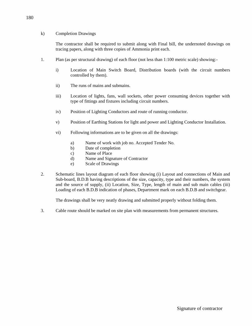
180
Signature of contractor
k) Completion Drawings
The contractor shall be required to submit along with Final bill, the undernoted drawings on
tracing papers, along with three copies of Ammonia print each.
1. Plan (as per structural drawing) of each floor (not less than 1:100 metric scale) showing:-
i) Location of Main Switch Board, Distribution boards (with the circuit numbers
controlled by them).
ii) The runs of mains and submains.
iii) Location of lights, fans, wall sockets, other power consuming devices together with
type of fittings and fixtures including circuit numbers.
iv) Position of Lighting Conductors and route of running conductor.
v) Position of Earthing Stations for light and power and Lighting Conductor Installation.
vi) Following informations are to be given on all the drawings:
a) Name of work with job no. Accepted Tender No.
b) Date of completion
c) Name of Place
d) Name and Signature of Contractor
e) Scale of Drawings
2. Schematic lines layout diagram of each floor showing (i) Layout and connections of Main and
Sub-board, B.D.B having descriptions of the size, capacity, type and their numbers, the system
and the source of supply, (ii) Location, Size, Type, length of main and sub main cables (iii)
Loading of each B.D.B indication of phases, Department mark on each B.D.B and switchgear.
The drawings shall be very neatly drawing and submitted properly without folding them.
3. Cable route should be marked on site plan with measurements from permanent structures.

181
Signature of contractor
TECHNICAL SPECIFICATION FOR CONDUIT WIRING SYSTEM
1.0 TYPE AND SIZE OF CONDUIT
All conduit pipe shall be screwed type, solid drawn or welded and with black stove enamelled surface
or galvanized and of thickness conforming to IS:9537 Part II of 1981 (or latest revision) in all respects.
The conduits are to be free from burrs and internal roughness. No conduits less than 20mm in dia shall
be used, unless specified.
2.0 ACCESSORIES
Only screwed type of accessories are to be used.
3.0 CONDUIT JOINTS
The conduit shall be properly earthed. In long distance straight runs of conduit inspection type screwed
couplers are to be provided at reasonable intervals on running threads with couplers and jamnuts.
Threads on conduit pipes in all cases shall be between 13mm to 27mm long sufficient to accommodate
pipes to full threaded portion of couplers or accessories. Cut end of conduit pipes shall have no sharp
edges or any burrs left to avoid damage to insulation of conductor while pulling them through such
pipes.
4.0 PROTECTION AGAINST DAMPNESS AND RUST
In order to minimize condensation and sweating inside the tube, all outlets of pipes system shall be
properly drained and ventilated, but in such a manner as to prevent entry to insects inside the conduit.
To protect against rust the outer surface of the conduit and accessories shall be painted and the bare
thread portion is to be painted with anti-corrosive preservative.
5.0 FIXING OF CONDUITS
Conduit pipes shall be fixed by heavy gauge saddles and h.w or metal bars, secured to wall/ceiling by
screws driven into wood plugs or rawl plugs or phil plugs at an interval of not more than 76 cm apart
for vertical run and 60cm apart for horizontal run. But on either side of couplers or bend of similar
fittings-saddle shall be fixed at a distance of 30cm from the centre of such fittings. The minimum
thickness for saddles shall be 24 SWG for conduits upto 25mm dia, ad 20 SWG for larger sizes.
6.0 BENDS IN CONDUITS
All necessary bends in the system including diversion shall be done by bending the pipes, or by
inserting suitable inspection type bends, elbows or similar fittings, or by fixing cast iron inspection
boxes whichever in most suitable.
7.0 OUTLETS
All outlets for fittings, switches etc. shall be fixed on boxes of suitable metal for either surface
mounting system or flush mounting system. In case of cast iron boxes the wall thickness shall be at
least 3mm and in case of welded mild steel sheet box the wall thickness shall not be less than 16 gauge.

182
Signature of contractor
Except where otherwise stated 3mm thick insulated laminated sheets shall be fixed on the front with
screws. Where conduits are terminated special care shall be taken in employing double jam nuts, for
securely fixing conduits to outlets so as to prevent any possibility of damages to cables when drawn.
8.0 CABLES TO BE USED
Unless stated otherwise only single core PVC insulated cables of approved manufactures shall be used
for wiring in conduit system. The number of single core cables drawn in one conduit shall not be
greater than maximum set out in Table II of Indian Standard (I.S 732-1963) Code of Practice (revised)
for electrical wiring installation (system voltage not exceeding 650 volts).
9.0 LOOPING IN SYSTEM
Distribution wiring in conduit to light, fan plug points etc. shall be done in looping system. In this
system no joints or connections shall be made anywhere of the system except at terminating points such
as at terminals of switches, ceiling roses, etc. and in case of socket outlets at the socket terminals.
10. EARTHING CONTINUITY WIRES
All three pin 6 Amps plug points and metallic fan regulator cover should be provided with earthing
attachment by No. 14 SWG G.I wires for surface wiring and 1 no. 1.5 sq.mm PVC insulated copper
wire for concealed wiring, unless specified otherwise.
Three pin 16 Amps power plug point should be provided with earthing attachment by No. 14 SWG G.I
wire for surface wiring and 1 no. 2.5 sq.mm PVC insulated copper wire for concealed wiring, unless
specified otherwise.
Conduits and accessories for surface distribution wiring should be provided with earthing attachment by
14 SWG G.I wire, unless specified otherwise.
For looping earthing G.I wire shall be run on conduits being fixed with saddles. This wire shall not be
normally visible after installation when run with the conduit. Where the wire has to be taken without
the conduits this will be fixed with „U‟ nails at 2 feet intervals.
11.0 PAINTING
Conduit and all conduit fittings and accessories shall be painted with two coats matt paint Painting of
conduits shall be done to harmonize with colour of bearing surface, i.e wall, joists, trusses etc. after
installation and as approved by the Engineer-in-Charge.
TECHNICAL SPECIFICATION FOR CONCEALED WIRING SYSTEM
1.0 Concealed conduit wiring system shall comply with all requirements for surface conduit wiring system
as specified above and in addition conform to the requirements specified below:
2.0 MAKING OF CHASE
The chase in the wall shall be neatly made and be of ample dimensions to permit the conduit to be fixed
in the manner desired.
3.0 FIXING OF CONDUIT IN CHASE

183
Signature of contractor
The conduit shall be fixed by means of staples, J-Hooks or by means of saddles not more than 60cm
apart. Fixing of standard bends or elbows shall be avoided as far as possible with a long radius bend
which will permit easy drawing in of conductors. All threaded joints of metallic conduits shall be
treated with some approved preservative to secure protection against rust.
4.0 INSPECTION BOXES
Suitable inspection boxes shall be provided when necessary to permit periodical inspection and to
facilitate removal of wires. These shall be mounted flush with wall.
For longer runs of conduit involving more than one bend, one inspection box/draw-in box shall be used
after one bend.
5.0 TYPES OF ACCESSORIES TO BE USED
All outlets such as switches, socket outlets, shall be flush mounting type with cast iron or MS boxes
with a cover of approved insulating material. The switches and other outlets shall be mounted on such
boxes as would be approved. The metal box shall be efficiently earthed with conduit by means of
earthing attachment with suitable size of PVC insulated copper wires running inside the conduit.
6.0 CONDUITS
i) Steel-Black enamelled type M.S conduits with thickness conforming to IS 9537 Part II of 1981
(or latest revision).
ii) PVC/Polythene-Medium gauge pipes of reputed make having 3 mm wall thickness shall be
used.
For roof slabs-These shall be prelaid during casting of floor/roof slab. No. of wires drawn
through the same shall not exceed the number of specified I.S Code.
For vertical drops in wall to switch boards-Minimum size shall be 20mm.
iii) Maximum capacity of conduits for drawing in of PVC insulated cables shall be as follows:
650/1100V PVC copper
wire In 20mm dia conduit In 25mm dia conduit In 32mm dia conduit
1.5 sq.mm 4 Nos 8 Nos 12 Nos 2.5 sq.mm 3 Nos 6 Nos 10 Nos 4.0 sq.mm 2 Nos. 6 Nos. 8 Nos 6.0 sq.mm 5 Nos 7 Nos
10.0 sq.mm 3 Nos 5 Nos
Maximum number of PVC insulated 650/1100V grade aluminium/copper conductor cable are as per CPWD
General Specification of Electrical Works Part-I (Internal), Page 41, 1994.
TABLE-I
Maximum number of PVC insulated 650/1100V grade aluminium/copper
conductor cable conforming to IS 694-1990

184
Signature of contractor
Nominal Cross
Sectional Area of
Conductor in
sq.mm
20mm 25mm 32mm 38mm 51mm 64mm
S B S B S B S B S B S B
1.50
5 4 10 8 18 12 - - - - -
2.50 5 3 8 6 12 10 - - - - - 4 3 2 6 5 10 8 - - - - - 6 2 - 5 4 8 7 - - - - - 10 2 - 4 3 6 5 8 6 - - - 16 - - 2 2 3 3 6 5 10 7 12 8 25 - - - - 3 2 5 3 8 6 9 7 35 - - - - - - 3 2 6 5 8 6 50 - - - - - - - - 5 3 6 5 70 - - - - - - - - 4 3 5 4
Note: 1. The above tables shows the maximum capacity of conduits for a simultaneous drawing
in of cables.
2. The columns headed „S‟ apply to runs of conduits which have distance not exceeding
4.25m between draw in boxes and which do not deflect from the straight by an angle or
more than 15 degrees. The columns headed „B‟ apply to runs of conduit which deflect
from the straight by an angle of more than 15 degrees.
3. Conduit sizes are the nominal external diameters.
7.0 FISH WIRE
18 S.W.G G.I wire shall be used and it shall protrude the conduit ends by 9 inches.
8.0 CONDUIT LAYING IN FLOOR / ROOF SLABS BEFORE CASTING
PVC/Polythene/G.I conduit shall be laid straight as far as practicable and property placed including
binding with the steel reinforcement rods with 22 SWG G.I wire so that proper positions of conduits are
maintained.
While laying the conduits for concealed wiring in the ceiling or in the beams and columns and before
casting the contractor shall ensure that both ends of the conduit are plugged by means of dean-end
socket or otherwise so that any foreign matter can not enter the conduit and choke them.
All precaution must be taken while laying the conduits on the slabs, R.C walls, columns etc. and the
contractor shall rectify at his own cost if any defects are found during process of drawing cables
through the concealed prelaid conduits.
Each PVC/polythene conduit shall be provided with protruding length of not less than 9 inches on free
end of the conduits.

185
Signature of contractor
There shall be no intermediate joints in one straight run of conduit.
All ceiling outlets shall be terminated in a round CI/GI circular box/deep box to suit standard size
ceiling rose or/and rectangular C.I/M.S junction box or Fan Hook Box as the case may be.
It will be mandatory for the contractor to get the layouts approved by the Engineer-in-charge/Architect
when the conduits are laid and bound to steel reinforcement rods, before he can release the work for
casting of floor/roof.
9.0 CONDUCTOR BOXES, DRAW-IN-BOXES: JUNCTION BOXES:
These shall be constructed from 16 SWG M.S sheet and have M.S cover. Minimum size for connector
boxes is 6” x 4” and for Draw-in-Boxes 4” x 4”.
10.0 FAN HOOK BOXES
These shall be 100mm (4”) dia x 75mm (3”) deep, constructed from 16 SWG M.S sheet, and provided
with one 12mm dia M.S rod 300mm (12” long).
11.0 PAINTING
Outside of wall switch boards, connector boxes & draw-in-boxes and other C.I/M.S accessories shall be
painted with two coats of anti-rust paint in addition to other painting instruction given elsewhere.
TECHNICAL SPECIFICATION FOR CABLE INSTALALTIONS
1.0 GENERAL
All HV Cables (upto 33KV earthed system) shall be either paper insulated SL type of XLPE insulated
aluminium conductor cable conforming to I.S 692 and I.S 7098 respectively.
All Medium Voltage and Low Voltage PVC insulated and armoured / unarmoured cables shall conform
to IS 1554 part-I-1964 and of 1,100 volt grade.
Old and used cables must not be used for installation. Only one make of cable shall be used. All cables
brought to site must be tested and got approved by the Engineer-in-Charge before these can be laid.
The cables shall be dispatched to site on wooden drums with ends sealed. Exact lengths shall be
determined by the Contractor after measurement at site.

186
Signature of contractor
The underground installation of cables shall be generally conforming to I.S 1255-1967. Code of
Practice for installation and maintenance of underground cables (upto including 33 KV).
2.0 LAYING OF CABLES
a) Direct in Ground
Trenches shall be 750mm deep (minimum) for LT Cables and 1.2 M (4‟0”) deep minimum) for
HT Cables from ground level and trenching work shall include all pumping and bailing out
water. These trenches shall be wide enough to accommodate all the cables with brick
separations as per the requirements specified in the relevant I.S.
When more than one multicore cable is to be laid in the same trench, a minimum horizontal
interaxial spacing between cables will be as per relevant I.S.
After excavation of the trench of proper size, the bottom of the trench shall be dressed and
leveled and filled with a 75mm layer of fine sand. The cable shall then be laid with bricks on
both sides of the cable continuously. After having the space within the bricks, filled and
packed upto a level of 75mm (3”) above top of cable with fine sand, the top layer of bricks shall
be placed side by side in continuous series as protective cover. Total No. of bricks required
being 16 per metre run. The remainder of the trench shall be filled with riddled soil, well
rammed and watered to a level of 75mm (3”) above surrounding ground level. The ground
level surface of the whole trench route shall be restored properly after completion of cable
laying.
b) Inside Building
Cables shall be laid on walls/ceiling/structure, unless specified otherwise, with M.S brackets
and suitable clamps or over claw type aluminium cleats fixed on M.S brackets, spaced out more
than 450mm apart. G.I Bolts of suitable sizes are to be grouted on the wall properly for fixing
the brackets.
c) Minimum bending radius permissible is 12D MV Cables and 20D for HV cables. At joints and
terminations, the individual core of multicore cables should never be bent so that the radius is
less than 15 times the diameter over the insulation.
No cable jointing is allowed between two terminal points.
3.0 CABLE JOINTING
All cable joints shall be carried out by experienced and Licenced jointers under strict
supervision. Electro plated brass cable glands, aluminium/tinned copper cable sockets and
approved jointing materials must be used. The price for cable jointing and finishing the ends of
the cable shall include all materials and shall also provide for tools and plants for the work.
The cable armouring is to be properly terminated. All cable accessories and other associated
materials shall conform to Indian Standard Specification where applicable. Proper earthing of
cable glands and armouring shall be included in the job.
4.0 TESTING OF CABLES

187
Signature of contractor
All cables shall be tested for insulation resistance with megger-5,000V constant pressure
megger insulation tester for HT Cables and 1,000V constant pressure megger for MV Cables,
before installation.
After installation and end termination, the cables shall be again subjected to the above test.
Insulation value of HT Cables shall not be less than 100 megohms and for MV Cables 1.0
megothm.
After laying and jointing, the HV Cables shall be subjected to high voltage pressure test before
commissioning, the test voltage being as specified in I.S 1255-1967 or latest.
5.0 TESTING OF INSTALLATION
Before the completed installation is put into service or handed over to Owner, the installation is
to be subjected to the above tests to the satisfaction of the Engineer-in-Charge. The completed
work will be taken over only if the results are acceptable to the Architects/Owner.
TECHNICAL SPECIFICATION FOR EARTHING INSTALLATION
The installation shall generally conform to IS 3043-Indian Standard Code of Practice for Earthing, as amended
upto date.
1.0 EARTHING
a) Pipe Electrode
The earthing electrode shall be galvanized steel pipe of Class B medium quality-50mm (2”) dia
bore and 3.04M (10‟) long. A hole shall be provided at 100mm (4”) from the top end to receive

188
Signature of contractor
a 12mm (1/2”) dia galvanized bolt and the bottom end shall be chisel cut for easy penetration
into soil.
A suitable trench shall be excavated about 0.45M (1‟-6”) deep and the pipe electrode driven to
an average depth of 3.35M (11‟-0”) below ground level. The top end of the electrode shall be
at an average depth of 0.30M (1‟-0”) below the ground surface.
Alternate layers of Charcoal or Salt and Coke to be provided for Electrode as per I.S Code of
Practice unless specified otherwise.
One no. 6 SWG G.I wire (unless otherwise specified) shall be connected securely on the
properly cleaned surface at the top end of pipe electrode by means of 1 100mm (4”) long x
13mm (1/2”) dia G.I bolts, double nuts and double washers. The earth lead conductor shall be
protected mechanically be means of a continuous length of G.I pipe (Class A) having 13mm
(1/2”) inside diameter upto a height of 0.60M (2‟-0”) above ground and the same shall be
completely filled with bitumen compound and topped upto overflowing.
b) Plate Electrode
Where plate electrode for earthing is to be employed, the size of all the plate shall not be less
than 0.6m x 0.6m x 6.3mm thickness for G.I plate and 0.6m x 0.6m x 3.15mm thickness in case
of copper plate.
The plate shall be buried vertically with the top at a minimum of 4.0M below the ground level
for sandy soil and 2.0M below the ground level for normal soil. In order to place the same at
the prescribed depth, the dimension of pit to be excavated shall be 0.9m x 0.9m x 3m deep.
The plate shall be placed in position by the contractor only after the inspection of excavated pit
and approval is obtained from the Architect/Engineer.
One no. 50mm x 6mm G.I flat (for electrical installation) or one no. 25mm x 6mm GI flat (for
Lighting conductor) should be connected to the plate at two points by means of 65mm lon
12mm dia galv bolts, nuts and galv washers. In case of copper plate copper flat of not less than
32mm x 6.0mm shall be used as the earth lead. Brass bolts, nuts and washers shall be used for
fixing. All other details shall be in accordance with IS 3043-1987. No joint on the earth lead
conductor is permitted. Every care be taken to ensure that the ends of the wire/flats have been
securely clamped by the bolt on cleaned surface of the plate and established a good electrical
contact.
After placing the plate the earth lead conductor shall be protected by means of a continuous
length of G.I pipe (Class-B) having 50mm dia bore or depending upon the size of the lead, right
from the plate upto a height of 0.60 metre (2 ft) above ground level. The whole length of pipe
shall be filled with bituminous compound of approved make and branch. The molten
compound shall be poured from the top end the pipe and topped upto overflowing.
The plate electrode shall have a 50mm galvanized iron water pipe buried vertically and adjacent
to the electrode and reaching upto the center of the plate. The upper end of the pipe shall be
atleast 5 cm above the bottom of the inspection pit and with wire mesh, funnel, etc as per IS
specification.
2.0 MASONRY INSPECTION PIT

189
Signature of contractor
The inspection pit for the earth station shall be approx. 0.56M x 0.56m (1‟-10” x 1‟-10”)
outside dimensions and approx 0.45m (1‟-6”) deep when completed, having 5” thick cement
brick work with 1st class bricks in cement mortar (6:1) both inside and outside plastered 19mm
(3/4”) thick and neatly cemented 1.60mm (1/16”) thick, both inside, outside and top. The
opening on top shall be provided with a C.I ring with lockable cover fixed flush with ground
surface.
All the excavations shall be duly back filled, dressed and rammed.
3.0 LOCATION FOR EARTH ELECTRODES
Electrodes shall be buried at least 2m (6‟-6”) away from the building pole or object to be
earthed. However, earthing electrodes for L.C installations should be as close to the down
conductors as possible.
Electrodes, when installed in parallel, shall not be placed than 2m (6‟-6”) apart and preferably
placed at distances greater than twice their lengths.
4.0 EARTH BUSBAR
a) Galvanised M.S Flat
The busbar shall be of suitable size and length, as specified in the Schedule of Items,
heavily galvanized and having adequate number of drilled and tapped holes 30mm
apart, complete with G.I bolts, nuts, washers for securely connecting the earth leads
and earth continuity conductors. The busbar shall be fixed on wall, having clearance of
6mm from wall with spacing insulators with at least 13mm (1/2”) G.I rag bolts spaced
about 0.46m (1‟-6”) apart.
b) Copper Flats:
To be used, as specified, in the Schedule of Items, where earthing requirements are
more stringent. Brass bolts, nuts washers shall be used for connections.
5.0 VALUE OF EARTH RESISTANCE
In case of installations where the load does not exceed 5 K.W the resistance to earth shall on no
account exceed 5 ohms. Where the load exceeds 5 K.W, the resistance shall not exceed 1 ohm.
For sub-stations, the value is 1 ohm.
For L.C installations, the value is 1 ohm.
LIST OF MATERIALS OF APPROVED MAKES/BRAND
The contractor shall use materials in their works subject to inspection prior to dispatch, by Owner or his
authorized representative of any materials, as deemed necessary in accordance with the following list. All
materials not otherwise specified shall be in accordance with the latest Indian Standard Specification, where

190
Signature of contractor
such exists and subject to prior approval of Owner / Architect. Contractor shall be bound to supply items of any
make of the items as per the choice of the Owner / Architect.
_______________________________________________________________________________________
Sl.No. Description Make
_______________________________________________________________________________________
1. L T Switch Board : Locally fabricated with all components from
SIEMENS / L&T / GE / HPL
2. CFS / Switch Fuse with HRC fuses : L&T/SIEMENS/GE / HPL
3. Switch fuse with rewireable type fuses : STANDARD/HPL/HAVELL
4. Isolator : HAVELL‟S/HPL/KENBER
5. Changeover switch : KENBAR/HAVELL‟S/ELCON/CONTROL
& SWITCHGEAR
6. MCCB : SIEMENS/L&T/GE/Legrand
7. MCB Distribution Board : Legrand/SIEMENS/L&T-HAGGER
8. RCBO & MCB : Legrand/SIEMENS/L&T-HAGGER
9. Current Transformers : AE/KAPPA/SEGC/ALSTHOM/L&T
KWH Meter:
10. Analogic Mechanical : ALSTHOM/IMP/ABB/LANDIS
GYR/JAIPUR/CAPITAL/HPL
11. Ammeter & Volt Meter : AE/IMP/MECO
12. Selector Switch for Voltmeter/Ammeter : Kaycee/L&T/Siemens
13. Contactors : SIEMENS/L&T/TELEMECHANIQUE /
YULE/ BCH
14. PVC Terminals : ESSEN/ELME/L&T
15. 1.1KV grade PVC insulated armoured : CCI/GLOSTER/UNIVERSAL
aluminium cables
16. 1100V grade PVC insulated and : RR-KABLE/MESCAB/RAJNIGANDHA/
sheathed and PVC insulated copper NATIONAL / HAVELL‟S / POLYCAB
conductor wire/flexible wire
17. Steel Conduit (ISI marked) : BEC/NIC/AKG
Black enamelled/galvanised

191
Signature of contractor
18. PVC Conduits/Channels : Garware/Plastran/Precision
19. 15 Amp/5 Amp Piano Key type switch : Anchor/SSK/PRECISION
and flushed type
20. Modular type switch/socket/MS box/ : Legrand-Mosaic/MK/Anchor/Woods/
plate Indo Asian-Hansmann
21. G.I Pipe : ITC/BSI/Jindal
22. Ceiling Rose : Anchor/Precision/SSK
23. Holder : Kay/MMP/EPP/Anchor/Precision
24. Buzzer/Call Bell : Bajaj/Anchor
25. Bulk Head Light Fittings : Philips/GEC/Crompton /Bajaj
26. Paint : Shalimar Paint Colour & Varnish Co Ltd /
Jenson & Nicholson (I) Ltd/ British Paint (I)
Ltd.
27. Contactor type DOL/Star-Delta Starter : SIEMENS/L&T/CROMPTON
GREAVES/GE

192
Signature of contractor
NOTES TO SCHEDULE OF ITEMS
1. Tenderers shall include in their rates quoted charges for preliminary and general items required for the
execution of work such as tools and plant, workman‟s shed, temporary offices, clearing, site,
scaffolding upto required height etc. The description of each item shall, unless otherwise stated be held
to include conveyance and delivery, unloading, storing, fabrication, hoisting, all labour and finishing to
required shape and size, setting, fitting and fixing in position, straight cutting and waste, return of
packings, overheads, profits and other incidental charges. All measurements of cutting shall unless
otherwise stated, be held to include the consequent waste.
2. The rates quoted by the Contractor should cover for work at any height for all the items of work under
this contract. List of materials will not form a criterion for any extra payment, unless otherwise stated
in the particular item.
In the event of arithmetical error/errors being discovered in the contractor‟s tender, the rates mentioned
in words in the Tender copy marked „Original‟ will only be taken as bonafide.
3. Contractor should note that the tender is strictly on item rate basis and their attention is drawn to the
fact that their rates for each every item should be correct, workable and self supporting. If called upon
by the Architects/Owner shall not be bound to recognize Contractor‟s analysis.
4. Contractors should note that their rates should be inclusive of all attendance on their sub-contractors
and also for making good any holes and chases left by the sub-contractors before the builder‟s work is
completed.
5. The contractor shall be responsible for procuring all required materials sufficiently in advance and see
that the work is never hindered for want of materials or due to any other reason including skilled labour
or restrictions.
6. The contractor shall have to carry out all connected work within the boundary of the proposed work and
inside the building if ordered to do so by the Architect/Owner at the rates quoted in the schedule of
Items.
7. The contractor is to study architectural and electrical drawings before commencing any work. In case
of discrepancy the contractor must report to the Architect / Owner immediately shall get the same
rectified before proceeding on.
8. The rats quoted for installation work shall include the necessary requirements of Indian Electricity Act
and Rules as well as NEC in force at the time of carrying out work.

193
Signature of contractor
9. All materials which shall be used in the work shall be as per specifications and must be from the list of
the approved materials as mentioned in the specifications. Samples of materials proposed to be used
shall be submitted for approval and nothing shall be used which are not approved. Employer have got
right to select any “make” of the approved list and tenderer shall have to supplying the same without
any price implication.
10. Workmanship of panels, installation of cables, etc should be proper.
11. Distribution Boards of reputed manufacturers specified in the list should be used instead of locally
fabricated ones.
12. Cables wherever laid in trenches should be arranged in proper formation and preferably with minimum
axial spacing of 150mm between the cables.
13. On one and the same control board two circuits of two phases from the same T.P Distribution Board
should not be brought.
14. The rates for service connection charges include the cost of metering connection of PVC cables, Cable
sockets, etc.
15. Distribution wiring shall include circuit wiring. No extra payment shall be made for circuit wiring.
16. Rates quoted for point wiring of PVC wires on surface shall include cost of switches, three plate ceiling
roses etc. on wooden board or partly concealed as stated in the Schedule of Items including earthing.
No extra cost for switches, ceiling roses, boards etc. shall be allowed.
17. Rates for conduit/pipe laying in roof/floor slab before casting shall include the cost of conduits/pipes,
junction boxes, bends, circular boxes, deep boxes, etc as necessary. No extra cost for the above shall be
allowed.
18. Rates quoted for point wiring in surface conduit/concealed conduit will include switches, etc on M.S
Board, three plate ceiling roses, circular boxes, deep boxes, junction boxes etc as specified and as
necessary including earthing. No extra cost for switches, ceiling roses boards etc. shall be allowed.
19. The rates for erection of ceiling fan and fluorescent fittings must include the cost of supplying down rod
as necessary and flexible wire, connection charges, earthing of fans and metallic fixtures, fixing of
Resistance type/Electronic type regulator as necessary and testing etc. If necessary fans with down rod
and fittings may be supplied by the Owner.
20. The rates for plug socket point wiring shall include the cost of socket-outlet, plug top and control switch
in box and necessary connection charge including earthing as specified.
21. The rates for fittings shall include cost of supply and fixing of fittings, lamps, etc and connection and
testing charges.
22. The rats for cable laying shall include the cost of cable trenches with tiles, sands etc. and also the cost
of saddle clamp (in case of surface wiring), providing G.I pipes under road-crossing , drain, etc.
necessary clamps etc.
23. The rates for cable jointing shall include the cost of labour and materials include gland, cable box
clamp, etc and armour/gland –earthing suitably as specified.

194
Signature of contractor
24. The rates for cable connection charges include the cost of making connection of cables, cable sockets
etc wherever required.
25. Cost of Danger board/Caution Notice shall be included in the testing, commission item.
26. The rates for earthing shall include the cost of jointing earthwire with busbar by means of cable sockets,
etc. and cost of earthing with specified earthwire. No deviation from the specification for earthing work
including earth stations will be accepted. Cost of required Caution Notices should be including in the
rates of earthing.
27. Tenderer shall note that the light fittings, ceiling fans, exhaust fans etc to be used in bulk quantities
shall be supplied by the purchaser as “free issue” for installation / execution purposes at one point at
site. All the subsequent strong, security, protection installation/erection, testing/commissioning will be
within the scope of the successful tenderer till the entire installation is handed over to the purchaser.
Tenderer shall include all the necessary cost for the above and no extra cost will be paid on this
account.
28. Stroning and protection of all materials at site fill erection, commissioning and handing over shall be at
the responsibility of successful tenderer without any extra cost.
29. The wiring includes painting of installations with two coats of approved paints, and painting should
match with the interior decoration of wall and ceiling. No extra charge for painting shall be entertained.
30. General spirit of the technical specification and method of measurement shall be as laid down in the
latest edition of I.S Code of Practice and stipulated in I.E Rules. Rates quoted for all items shall include
for the cost of supplying, laying and materials fixing and/or erection complete with all the appliances
necessary for the proper execution and carrying out of the wok to the truest sense of drawing and
specification though this may not be mentioned in particular item of work in the Schedule of Items.

195
Signature of contractor
TO BE SUBMITTED IN ENVELOP NO - 02
B.O.B REGIONAL OFFICE MUZAFFARPUR
2nd
FLOOR KRISHNA HONDA BUILDING
AKHARAGHAT ROAD,
MUZAFFARPUR - 842001.
BIHAR
FINANCIAL/ PRICE BID - PART ll
FOR CONSTRUCTION OF RSETI BUILDING
AT “SHEOHAR” MUZAFFARPUR
ISSUED TO M/S
________________________________________________
________________________________________________
________________________________________________

196
Signature of contractor
ARCHITECT:
M/S RAM LAKSHMAN & SKY ASSOCIATE
Architect, Interior Designer & Valuer
„ASHA‟ 9Th
Avenue ,South park ,BISTUPUR
JAMSHEDPUR-831001
Contact Persons:
Jaideep Naryan (S.r Technical Manager)-0612-2557610
S. K Sinha (Director RSETI Sheohar) -0622-257035
ABSTRACT SHEET FOR CONSTRUCTION OF RSETI BUILDING AT SHEOHAR
SL No
DESCRIPTION OF WORK
AMOUNT
1 AMOUNT OF CIVIL WORK (Grand total Sub head A)
2 AMOUNT OF ELECTRICAL WORK (Grand total Sub head B)
3 AMOUNT OF P.H.E Work (Grand total Sub head C)
4 SITE DEVELOPMENT & BOUNDARY WALL (Grand total Sub head D)
Grand total – With all tax, royalties & Carriage

197
Signature of contractor
PROPOSED B.O.Q FOR CIVIL WORK IN RSETI AT SHEOHAR
SUB HEAD A ( CIVIL WORK IN BUILDING) ,GROUND ,1St & 2nd FLOOR )
SL No Ref Description Unit Quantity Rate Amount
Section 1 (Footing & Other work up to Plinth Level)
1 Earth Excavation :-Earth work in excavation in foundation trenches (not exceeding 1.5 m in width or 10 sqm on plan) including dressing of sides and ramming of bottoms, lift upto 1.5 m . including getting out the excavated soil and disposal of surplus excavated soil as directed, within a lead of 50 m.
All Kinds of Soil Cum 1792.0
2 Ploughing the existing ground for tie beam & fin to a depth ot 15 cm to 25 cm and watering the same
All kinds of soil. sqm 39.0
3 Re felling of soil:- Filling available excavated earth (excluding rock) in trenches, plinth,of foundations etc. in layers not exceeding 20 cm in depth: consolidating each deposited layer by ramming and watering lead.
cum 1728.0
4 Sand filling:- Supplying and Filling in plinth 610mm & 50mm Th Sand filling in footing trench and level with local sand and under floors including, watering, ramming consolidating and dressing complete.
cum 143.0

198
Signature of contractor
5 Brick flat Soiling in Foundation :-Providing designation 100 B one brick flat soling in foundation trench & below tie beam joints filled with local sand including cost of watering, taxes, royalty all complete as per building specification and direction of E/l.
sqm 211.0
6 P.C.C In Foundation:- Providing and laying in position 75mm Th cement concrete of specified grade excluding the cost of centring and shuttering-all work up to plinth level.
1.4.8 (1 Cement :4 coarse sand :8 graded stone aggregate 40 mm nominal size)
cum
11
R.C.C work in Footing , Tie beam & Column up to P.L
7 Providing and laying in position machine batched, machine mixed and machine vibrated design mix cement concrete of specified grade for reinforced cement concrete structural elements, excluding the cost of centring, shuttering finishing and reinforcement, M-20 grade reinforced cement concrete. 1:1:5:3(1 cement: 1.5 coarse sand:3 graded stone aggregate 20 mm nominal size)
All work upto plinth level cum 76
Brick work
8 250mm Th Brick work with bricks of class designation 100A above tie beam up to plinth in :
Cement mortar 1:6 (1 cement: 6 coarse sand )
cum 23
9 D.P.C :- Providing and laying damp-proof Course 50 mm thick with cement concrete 1:2:4(1cement:2:2 coarse sand :4 graded stone aggregate 20mm nominal size)
sqm 23
10 Extra for providing and mixing water prodding material in cement concrete work in the proportion mixing cement concrete in mixer with 5% Cisco or any other water proffing compound as per building specification and direction of E/I.Note- Mixing water proofing material @1Kg/ bag of cement.
per 50 kg
cement/1bag
cement @1Kg cisco
5.5

199
Signature of contractor
11 Centring and shuttering:- Centring and shuttering including strutting, propping etc. up to plinth level and removal of form for.
Foundations, footings, bases of columns etc. for mass concrete.
sqm 39
Lintels, beams, plinth beams, girders, ressumers and cantilevers.
sqm 50
Columns, Pillars, Piers, Abutments, Posts and Struts
sqm 76
12 Reinforcement in footing,column & Tie beam up to plinth Level
Reinforcement for R.C.C. work including straightening, cutting, bending, placing in position and binding all complete.
Thermo-Mechanically Treated bars TMTC-500-8mm dia.
kg 21
Thermo-Mechanically Treated bars TMTC-500-10mm dia.
kg 362
Thermo-Mechanically Treated bars TMTC-500-12mm dia.
kg 1709
Thermo-Mechanically Treated bars TMT Fe-500-I6mrn dia.
kg 192
Total Section l :-
Section ll (Super structure at Ground floor above plinth Lev)
Brick work
13 250mm Th Brick work with bricks of class designation 100A above plinth up to 1St Floor Level in :
Cement mortar 1:6 (1 cement: 6 coarse sand )
cum 64
14 125mm Th Half brick masonry with bricks of class designation 100A above plinth up to 1St floor Level in :
Cement mortar 1:4 (1 cement: 4 coarse send)
sqm 153
15 Extra for providing and placing in position 2 Nos, 6 mm dia , MS bars at every third course of half brick masonry.
sqm 153

200
Signature of contractor
R.C.C work in Column ,Lintel beam & Chhaja ,Roof
beam & roof Slab up to 1St Floor Level
16 Providing and laying in position machine batched, machine mixed and machine vibrated design mix cement concrete of specified grade for reinforced cement concrete structural elements, excluding the cost of centring, shuttering finishing and reinforcement, M-20 grade reinforced cement concrete. 1:1:5:3(1 cement: 1.5 coarse sand:3 graded stone aggregate 20 mm nominal size)
All work above plinth level(Walls columns, pillars, posts cind struts)
cum 9.5
Beams, planth beams, girders, bressumers, contilevers,Suspended floors lintels roofs and staircases including spiral staircases, shelves etc
cum 102
17 Centring & Shuttering :- Centring and shuttering including strutting, propping etc.above plinth up to floor level and removal of form for.
Suspended floors, roofs, landings, balconies and access platform.
sqm 256
Lintels beam,roof beams, and cantilevers.
sqm 59
Columns, Pillars, Piers, Abutments, Posts and Struts
sqm 142
Stairs,(excluding landings) except spiral-staircases.
sqm 9.5
Chhaja ,Perdi, Vertical and horizontal fins individually or forming box louvers band, facias and eaves boards
sqm 6
Reinforcement in column,Lintel beam,Stair roof beam & roof slab up
to 1St floor Level
18 Reinforcement for R.C.C. work including straightening, cutting, bending, placing in position and binding all complete.
Thermo-Mechanically Treated bars TMTC-500-8mm dia.
kg 1462
Thermo-Mechanically Treated bars TMTC-500-10mm dia.
kg 855
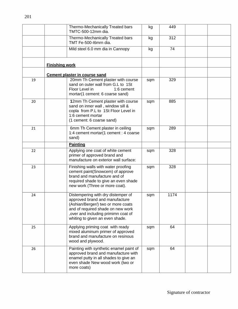
201
Signature of contractor
Thermo-Mechanically Treated bars TMTC-500-12mm dia.
kg 449
Thermo-Mechanically Treated bars TMT Fe-500-I6mrn dia.
kg 312
Mild steel 6.0 mm dia in Cannopy kg 74
Finishing work
Cement plaster in course sand
19 20mm Th Cement plaster with course sand on outer wall from G.L to 1St Floor Level in 1:6 cement mortar(1 cement: 6 coarse sand)
sqm 329
20 12mm Th Cement plaster with course sand on inner wall , window sill & copla from P.L to 1St Floor Level in 1:6 cement mortar (1 cement: 6 coarse sand)
sqm 885
21 6mm Th Cement plaster in ceiling 1:4 cement mortar(1 cement : 4 coarse sand)
sqm 289
Painting
22 Applying one coat of white cement primer of approved brand and manufacture on exterior wall surface:
sqm 328
23 Finishing walls with water proofing cement paint(Snowcem) of approve brand and manufacture and of required shade to give an even shade new work (Three or more coat).
sqm 328
24 Distempering with dry distemper of approved brand and manufacture (Ashian/Berger/) two or more coats and of required shade on new work ,over and including primimn coat of whiting to given an even shade.
sqm 1174
25 Applying priming coat with ready mixed aluminum primer of approved brand and manufacture on resinous wood and plywood.
sqm 64
26 Painting with synthetic enamel paint of approved brand and manufacture with enamel putty in all shades to give an even shade New wood work (two or more coats)
sqm 64

202
Signature of contractor
27 With ready mixed zinc chromate yellow primer of approved brand and manufacture on steel galvanized iron/steel works
sqm 39
28 Painting with synthetic enamel paint of approved brand and manufacture with enamel putty in all shades to give an even shade New steel work (two or more coats)
sqm 39
Flooring work
29 Brick Flat soiling :- Providing designation 100 B one brick flat soling joints filled with local sand including cost of watering, taxes, royalty all complete as per building specification and direction of E/l,
sqm 233.0
30 P.C.C Flooring:- 40mm Th cement concrete flooring 1:2:4(1Cement:2 Coarse:4 Grade stone aggregate)finished with a floating coat of neat cement including cement slurry etc.
sqm 233
31 Skirting :- 18mm Th Cement plaster skirting (up to 15 Cm height) with cement mortar 1:3(1Cement : 3 coarse sand ) finished with a floating coat of neat cement .
sqm 27.5
32 Ceramic Floot tile in Toilet :- Providing and laying Ceramic glazed floor tiles 300x300 mm (thickness to be specified by the manufacturer) of ist quality conforming to IS : 15622 of approved make in colours such as white , Ivory , Grey , Fume Red , Brown , laid on 20 mm thick Cement motar 1:4 (1 cement: 4 coarse sand ) including pointing the joints with white cement and matching pigment etc., complete.
sqm 24
33 Ceramic wall tile for Dado :- Providing and fixing 1st quality ceramic glazed wall tiles conforming to IS : 15622 (Thickness to be specified by the manufacture) of approved make in all colours, shades except burgundy , bottle green , black of any size as approved by Engineer-in-charge in dados over 12 mm thick bed of cement Motar 1:3(1 cement: 3 coarse sand ) and jointing with grey cement slurry @ 3.3 kg per sqm including pointing in
sqm 68

203
Signature of contractor
white cement mixed with pigment of matching shade complete.
Door & Window
34 Collapsible door :- Providing and fixing in position collapsible steel shutters with vertical channes 20x10x2 mm and braced with flat iron diagonals 20x5 mm size with top and bottom rail of T-tron 40x40x6 mm with 40 mm dia steel pulleys complete with bots.nuts locking arrangement stoppers handies including applying a priming coat of approved steel primer.
sqm 11
35 Door chowkhat :-Providing and fixing pressed steel door frame confirming IS code 351 manufactured from commerical mild steel sheet of 1.25 mm thickness including hinges, jamb, lock jamb, bead and if required angle threshold of mild steel angle of section 50 x 25 mm or base ties of 1.25mm pressed mild steel welded or rigidly fixed together by . mechnical means, adjustable lugs with split end tail to each jamb including steel butt hinges 2.5 mm thick with mortar guards, lock strike-plate and shock absorbers as specified and applying a coat of approved steel primer after pre-treatment of the surface as directed by Engineer-in-charge: Profile C
meter 16.5
36 Door Shutter:-Providing and fixing 35mm Th flush door shutters non-decorative type,core of block board construction with frame of 1 st class hard wood and well matched commercial 3 ply veneering with vertical grains or cross bands and face veneers on both faces of shutters. including anodized aluminum butt hinges with necessary screws.
sqm 32
37 Extra for providing lipping with 2nd class teak wood battens 25 mm minimum depth on all edges of shutters (overall area of door shutter to be measured)
sqm 32
38 Extra for providing vision panel not exceeding 0.1 sqm in Director chamber,Adm Office,Guest facuilty, of flush doors (cost of glas excluded),
sqm 1

204
Signature of contractor
39 Providing and fixing 85mmx42mm oxidised M.S. pull bolt lock conforming to IS:7534 with necessary screws bolts nut and washers etc. complete
each 8.5
40 providing 40x5 mm flat iron hold fast 40 cm long including fixing to frame with 10 mm diameter bots,nuts and wooden plugs and embeddings in cement concrete block 30x10x15 cm 1:3:6 mix (1 cement :3 coarse sand :6 graded stone aggregate 20 mm nominal size)
each 184
41 Providing and fixing oxidised M.S.tower bolt 150x10mm black finish in toilet,(barrel type) with necessary screws etc.complete
each 13
42 Providing and fixing bright finisned brass 100mm mortice latch and lock with 6 lever handles with necessary screws etc. complete.(best make of approved quality) ,Director chamber, Adm office,guest faculity& Library.
each 4
43 Providing and fixing bright finished brass hangging type floor door stoper with necessary screws etc. compelte.
each 8
44 Providing and fixing IS:3564 bright finished brass hydraulic door closer (best make of approved quality) with necessary accessories and screws etc. coplete.Director Chamber & Facuilty room.
each 2
45 Providing and fixing 125 mm long M.S.handles with necessary screws etc.complete
Each 61
46 Window grill :- Providing and fixing M.S. grills of requirement pattern in frames of windows etc. with M.S. flats bars 5mm Th & 20mm wide or 10mm x 10mm square bars @ 100mm C/C Vertical /horizontal etc.all complete, fixed to openings/wooden frames with rawl plugs screws etc.
kg 60

205
Signature of contractor
47 Steel glazed window :- Providing and fixing steel glazed windows and ventilatrs of standard rolled steel sections, joints mitered and welded with 15x3 mm lugs 10 cm long with steel lugs embedded in cement concrete blocks 15x10x10 cm of 1:3:6(1 cement: 3 coarse sand : 6 graded stone aggregate 20 mm nominal size) or with woodenplugs and screws or rawl plugs and screws or with fixing clips or with bolts and nuts as required, including providing and fixing of glass panes with glazing clips and special metal-sash putty of approved make complete including applying a priming coat of approved steel primer; excluding the cost of metal beading and other fitting except necessary hinges or pivots as required.
Sqm 40
48 Providing and fixing M.S.fan clamp type 1 of 16 mm dia.M.S. bar bent to shape with hooked ends in R.C.C slabs during laying including painting the exposed portion of loop,all as per standard design complete.
each 23
49 Providing and fixing circular cast iron box for ceiling fan clamp 140 mm internal dia, 73 mm height, 5 mm thick rim bottom and top lids, 1.5 mm thick M.S sheet with its top surface hacked for proper bonding top lid shall be screwed into the cast iron box by means of 3.3 mm dia round headed screws, one ;pcf at the corners. Clamps shall be made of 12 mm dia M.S. bar bent to shape as per standard drawing.
each 23
50 Steel work welded in built up sections/framed work including cutting hoisting, rixing in position and applying a priming coat of approved steel primer using structural steel, etc. as required. M.S Baluster 10mmx10mmx900mm each steps ,mild steel flats bar 25mmx5mm over baluster.
kg 35

206
Signature of contractor
51 Providing and fixing hand rail G.I Pipes 40 mm normal bore by welding etc. to steel ladder railings & staircases railing including applying a priming coat of approved steel primer . In stringers, treads landings etc. of stair cases.
kg 90
52 Making 0.45M Wide plinth protection 50mm thick of cement concrete 1:3:6 (1 cement :3 coarse sand : 6 graded stone aggregate 20 mm nominal size) over 75mm thick bed of dry brick ballast 40 mm nominal size, well rammed and consolidated and grouted with fine sand including finishing the top smooth.
sqm 38
Total Section ll:-
Section lll (Super structure at 1St floor Level)
Brick work
53 250mm Th Brick work with bricks of class designation 100A at 1St Floor Level in :
Cement mortar 1:6 (1 cement: 6 coarse sand )
cum 52
54 125mm Th Half brick masonry with bricks of class designation 100A above plinth up to 1St floor Level in :
Cement mortar 1:4 (1 cement: 4 coarse send)
sqm 76
55 Extra for providing and placing in position 2 Nos, 6 mm dia , MS bars at every third course of half brick masonry.
sqm 76
R.C.C work in Column ,Lintel beam & Chhaja ,Roof beam & roof Slab ,Cooking platform

207
Signature of contractor
56 Providing and laying in position machine batched, machine mixed and machine vibrated design mix cement concrete of specified grade for reinforced cement concrete structural elements, excluding the cost of centring, shuttering finishing and reinforcement, M-20 grade reinforced cement concrete. 1:1:5:3(1 cement: 1.5 coarse sand:3 graded stone aggregate 20 mm nominal size)
All work above plinth level(Walls columns, pillars, posts cind struts)
cum 7
57 Beams, planth beams, girders, bressumers, contilevers,Suspended floors lintels roofs and staircases including spiral staircases, shelves etc
cum 75
58 Centring & Shuttering :- Centring and shuttering including strutting, propping etc. at 1St floor level and removal of form for.
Suspended floors, roofs, landings, balconies and access platform.
sqm 213
Lintels beam,roof beams, and cantilevers.
sqm 46
Columns, Pillars, Piers, Abutments, Posts and Struts
sqm 111
Stairs,(excluding landings) except spiral-staircases.
sqm 11
Chhaja ,Perdi, Vertical and horizontal fins individually or forming box louvers band, facias and eaves boards
sqm 12.5
Reinforcement in column,Lintel beam,Stair roof beam & roof slab
59 Reinforcement for R.C.C. work including straightening, cutting, bending, placing in position and binding all complete.
Thermo-Mechanically Treated bars TMTC-500-8mm dia.
kg 1454
Thermo-Mechanically Treated bars TMTC-500-10mm dia.
kg 855
Thermo-Mechanically Treated bars TMTC-500-12mm dia.
kg 142
Thermo-Mechanically Treated bars TMT Fe-500-I6mrn dia.
kg 210

208
Signature of contractor
Mild steel 6.0 mm dia in Cannopy kg 47
Finishing work
Cement plaster in course sand
60 20mm Th Cement plaster with course sand on outer wall at 1St Floor Level in 1:6 cement mortar(1 cement: 6 coarse sand)
sqm 326
61 12mm Th Cement plaster with course sand on inner wall , window sill & copla from P.L to 1St Floor Level in 1:6 cement mortar (1 cement: 6 coarse sand)
sqm 311
62 6mm Th Cement plaster in ceiling 1:4 cement mortar(1 cement : 4 coarse sand)
sqm 246
Painting
63 Applying one coat of white cement primer of approved brand and manufacture on exterior wall surface:
sqm 325
64 Finishing walls with water proofing cement paint(Snowcem) of approve brand and manufacture and of required shade to give an even shade new work (Three or more coat).
sqm 325
65 Distempering with dry distemper of approved brand and manufacture (Ashian/Berger/) two or more coats and of required shade on new work ,over and including primimn coat of whiting to given an even shade.
sqm 559
66 Applying priming coat with ready mixed aluminum primer of approved brand and manufacture on resinous wood and plywood.
sqm 96
67 Painting with synthetic enamel paint of approved brand and manufacture with enamel putty in all shades to give an even shade New wood work (two or more coats)
sqm 96
68 With ready mixed zinc chromate yellow primer of approved brand and manufacture on steel galvanized iron/steel works
sqm 46

209
Signature of contractor
69 Painting with synthetic enamel paint of approved brand and manufacture with enamel putty in all shades to give an even shade New steel work (two or more coats)
sqm 46
Flooring work
70 P.C.C Flooring:- 40mm Th cement concrete flooring 1:2:4(1Cement:2 Coarse:4 Grade stone aggregate)finished with a floating coat of neat cement including cement slurry etc.
sqm 161
71 Skirting :- 18mm Th Cement plaster skirting (up to 15 Cm height) with cement mortar 1:3(1Cement : 3 coarse sand ) finished with a floating coat of neat cement .
sqm 26.5
72 Providing and laying 20mm Th Granite slab on cooking platform.
Sqm 3.50
73 Ceramic Floot tile in Toilet :- Providing and laying Ceramic glazed floor tiles 300x300 mm (thickness to be specified by the manufacturer) of ist quality conforming to IS : 15622 of approved make in colours such as white , Ivory , Grey , Fume Red , Brown , laid on 20 mm thick Cement motar 1:4 (1 cement: 4 coarse sand ) including pointing the joints with white cement and matching pigment etc.,
sqm 21
74 Ceramic wall tile for Dado :- Providing and fixing 1st quality ceramic glazed wall tiles in toilet up to 1.8M & above cooking platform,shink & wash basin up to 0.61M height ,conforming to IS : 15622 (Thickness to be specified by the manufacture) of approved make in all colours, shades except burgundy , bottle green , black of any size as approved by Engineer-in-charge in dados over 12 mm thick bed of cement Motar 1:3(1 cement: 3 coarse sand ) and jointing with grey cement slurry @ 3.3 kg per sqm including pointing in white cement mixed with pigment of matching shade complete.
sqm 61
Door & Window

210
Signature of contractor
75 Door chowkhat :-Providing and fixing pressed steel door frame confirming IS code 351 manufactured from commerical mild steel sheet of 1.25 mm thickness including hinges, jamb, lock jamb, bead and if required angle threshold of mild steel angle of section 50 x 25 mm or base ties of 1.25mm pressed mild steel welded or rigidly fixed together by . mechnical means, adjustable lugs with split end tail to each jamb including steel butt hinges 2.5 mm thick with mortar guards, lock strike-plate and shock absorbers as specified and applying a coat of approved steel primer after pre-treatment of the surface as directed by Engineer-in-charge: Profile C
meter 33
76 Door Shutter:-Providing and fixing 35mm Th flush door shutters non-decorative type,core of block board construction with frame of 1 st class hard wood and well matched commercial 3 ply veneering with vertical grains or cross bands and face veneers on both faces of shutters. including anodized aluminum butt hinges with necessary screws.
sqm 48
77 Extra for providing lipping with 2nd class teak wood battens 25 mm minimum depth on all edges of shutters (overall area of door shutter to be measured)
sqm 48
78 Providing and fixing 85mmx42mm oxidised M.S. pull bolt lock conforming to IS:7534 with necessary screws bolts nut and washers etc. complete
each 16
79 providing 40x5 mm flat iron hold fast 40 cm long including fixing to frame with 10 mm diameter bots,nuts and wooden plugs and embeddings in cement concrete block 30x10x15 cm 1:3:6 mix (1 cement :3 coarse sand :6 graded stone aggregate 20 mm nominal size)
each 184
80 Providing and fixing oxidised M.S.tower bolt 150x10mm black finish in toilet,(barrel type) with necessary screws etc.complete
each 12

211
Signature of contractor
81 Providing and fixing bright finished brass hangging type floor door stoper with necessary screws etc. compelte.
each 15
82 Providing and fixing IS:3564 bright finished brass hydraulic door closer (best make of approved quality) with necessary accessories and screws etc.in Domitory.
each 4
83 Providing and fixing 125 mm long M.S.handles with necessary screws etc.complete
Each 72
84 Window grill :- Providing and fixing M.S. grills of requirement pattern in frames of windows etc. with M.S. flats bars 5mm Th & 20mm wide or 10mm x 10mm square bars @ 100mm C/C Vertical /horizontal etc.all complete, fixed to openings/wooden frames with rawl plugs screws etc.
kg 68
85 Steel glazed window :- Providing and fixing steel glazed windows and ventilatrs of standard rolled steel sections, joints mitered and welded with 15x3 mm lugs 10 cm long with steel lugs embedded in cement concrete blocks 15x10x10 cm of 1:3:6(1 cement: 3 coarse sand : 6 graded stone aggregate 20 mm nominal size) or with woodenplugs and screws or rawl plugs and screws or with fixing clips or with bolts and nuts as required, including providing and fixing of glass panes with glazing clips and special metal-sash putty of approved make complete including applying a priming coat of approved steel primer; excluding the cost of metal beading and other fitting except necessary hinges or pivots as required.
Sqm 45
86 Providing and fixing M.S.fan clamp type 1 of 16 mm dia.M.S. bar bent to shape with hooked ends in R.C.C slabs during laying including painting the exposed portion of loop,all as per standard design complete.
each 23

212
Signature of contractor
87 Providing and fixing circular cast iron box for ceiling fan clamp 140 mm internal dia, 73 mm height, 5 mm thick rim bottom and top lids, 1.5 mm thick M.S sheet with its top surface hacked for proper bonding top lid shall be screwed into the cast iron box by means of 3.3 mm dia round headed screws, one ;pcf at the corners. Clamps shall be made of 12 mm dia M.S. bar bent to shape as per standard drawing.
each 23
88 Water Proofing :- Providing and laying water proofing treatment to vertical and horizontal surfaces of depressed portions of W.C. kitchen and the like consisting of: (i) 1st course of applying cement slurry @ 4.4 kg/sqm mixed with water proofing compound conforming tc IS 2645 in recommended proportions. (ii) 11 nd course of 20 mm cement plaster 1:3(1 cement:3 coarse sand)mixed with water proofing compound in recommended proportion, (iii) Illrd course of applying blown or/residual bitumen aplied hot at 1.7 kg. per sqm of area, (iv) Ivth course of 400 micron thick PVC sheet.(Overlaps at joints of PVC shet should be 100 mm wide and pasted to each other with bitumen @ 1.7 kg/sqni).
sqm 30
89 Steel work welded in built up sections/framed work including cutting hoisting, rixing in position and applying a priming coat of approved steel primer using structural steel, etc. as required. M.S Baluster 10mmx10mmx900mm each steps ,mild steel flats bar 25mmx5mm over baluster.
kg 35
90 Providing and fixing hand rail G.I Pipes 40 mm normal bore by welding etc. to steel ladder railings & staircases railing including applying a priming coat of approved steel primer . In stringers, treads landings etc. of stair cases.
kg 90
Total Section lll:-

213
Signature of contractor
SECTION IV -AT SECOND FLOOR
Brick work
91 250mm Th Brick work with bricks of class designation 100A at 1St Floor Level in :
Cement mortar 1:6 (1 cement: 6 coarse sand )
cum 56
92 125mm Th Half brick masonry with bricks of class designation 100A above plinth up to 1St floor Level in :
Cement mortar 1:4 (1 cement: 4 coarse send)
sqm 26
93 Extra for providing and placing in position 2 Nos, 6 mm dia , MS bars at every third course of half brick masonry.
sqm 26
R.C.C work in Column ,Lintel beam & Chhaja ,Roof beam & roof Slab ,Cooking platform
94 Providing and laying in position machine batched, machine mixed and machine vibrated design mix cement concrete of specified grade for reinforced cement concrete structural elements, excluding the cost of centring, shuttering finishing and reinforcement, M-20 grade reinforced cement concrete. 1:1:5:3(1 cement: 1.5 coarse sand:3 graded stone aggregate 20 mm nominal size)
All work above plinth level(Walls columns, pillars, posts cind struts)
cum 6.5
Beams, planth beams, girders, bressumers, contilevers,Suspended floors lintels roofs and staircases including spiral staircases, shelves etc
cum 56
95 Centring & Shuttering :- Centring and shuttering including strutting, propping etc. at 1St floor level and removal of form for.
Suspended floors, roofs, landings, balconies and access platform.
sqm 205
Lintels beam,roof beams, and cantilevers.
sqm 102

214
Signature of contractor
Columns, Pillars, Piers, Abutments, Posts and Struts
sqm 96
Stairs,(excluding landings) except spiral-staircases.
sqm 12
Chhaja ,Perdi, Vertical and horizontal fins individually or forming box louvers band, facias and eaves boards
sqm 12
Reinforcement in column,Lintel beam,Stair roof beam & roof slab
96 Reinforcement for R.C.C. work including straightening, cutting, bending, placing in position and binding all complete.
Thermo-Mechanically Treated bars TMTC-500-8mm dia.
kg 1426
Thermo-Mechanically Treated bars TMTC-500-10mm dia.
kg 855
Thermo-Mechanically Treated bars TMTC-500-12mm dia.
kg 17
Thermo-Mechanically Treated bars TMT Fe-500-I6mrn dia.
kg 98
Mild steel 6.0 mm dia in cannopy kg 47
Finishing work
Cement plaster in course sand
97 20mm Th Cement plaster with course sand on outer wall at 1St Floor Level in 1:6 cement mortar(1 cement: 6 coarse sand)
sqm 173
98 12mm Th Cement plaster with course sand on inner wall , window sill & copla from P.L to 1St Floor Level in 1:6 cement mortar (1 cement: 6 coarse sand)
sqm 235
99 6mm Th Cement plaster in ceiling 1:4 cement mortar(1 cement : 4 coarse sand)
sqm 132
Painting
100 Applying one coat of white cement primer of approved brand and manufacture on exterior wall surface:
sqm 175
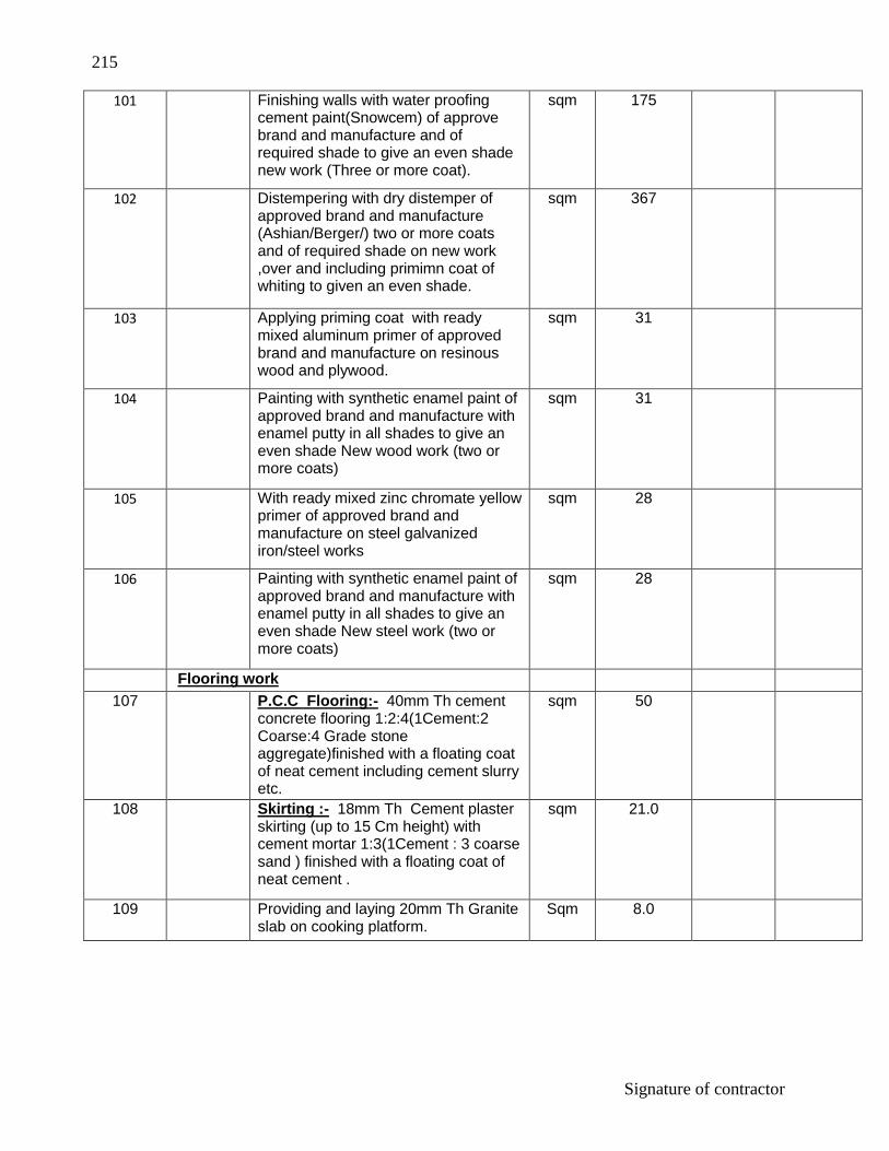
215
Signature of contractor
101 Finishing walls with water proofing cement paint(Snowcem) of approve brand and manufacture and of required shade to give an even shade new work (Three or more coat).
sqm 175
102 Distempering with dry distemper of approved brand and manufacture (Ashian/Berger/) two or more coats and of required shade on new work ,over and including primimn coat of whiting to given an even shade.
sqm 367
103 Applying priming coat with ready mixed aluminum primer of approved brand and manufacture on resinous wood and plywood.
sqm 31
104 Painting with synthetic enamel paint of approved brand and manufacture with enamel putty in all shades to give an even shade New wood work (two or more coats)
sqm 31
105 With ready mixed zinc chromate yellow primer of approved brand and manufacture on steel galvanized iron/steel works
sqm 28
106 Painting with synthetic enamel paint of approved brand and manufacture with enamel putty in all shades to give an even shade New steel work (two or more coats)
sqm 28
Flooring work
107 P.C.C Flooring:- 40mm Th cement concrete flooring 1:2:4(1Cement:2 Coarse:4 Grade stone aggregate)finished with a floating coat of neat cement including cement slurry etc.
sqm 50
108 Skirting :- 18mm Th Cement plaster skirting (up to 15 Cm height) with cement mortar 1:3(1Cement : 3 coarse sand ) finished with a floating coat of neat cement .
sqm 21.0
109 Providing and laying 20mm Th Granite slab on cooking platform.
Sqm 8.0

216
Signature of contractor
110 Ceramic Floot tile in Toilet :- Providing and laying Ceramic glazed floor tiles 300x300 mm (thickness to be specified by the manufacturer) of ist quality conforming to IS : 15622 of approved make in colours such as white , Ivory , Grey , Fume Red , Brown , laid on 20 mm thick Cement motar 1:4 (1 cement: 4 coarse sand ) including pointing the joints with white cement and matching pigment etc., complete.
sqm 6.5
111 Ceramic wall tile for Dado :- Providing and fixing 1st quality ceramic glazed wall tiles in toilet up to 1.8M & above cooking platform,shink & wash basin up to 0.61M height ,conforming to IS : 15622 (Thickness to be specified by the manufacture) of approved make in all colours, shades except burgundy , bottle green , black of any size as approved by Engineer-in-charge in dados over 12 mm thick bed of cement Motar 1:3(1 cement: 3 coarse sand ) and jointing with grey cement slurry @ 3.3 kg per sqm including pointing in white cement mixed with pigment of matching shade complete.
sqm 27
Door & Window
112 Door chowkhat :-Providing and fixing pressed steel door frame confirming IS code 351 manufactured from commerical mild steel sheet of 1.25 mm thickness including hinges, jamb, lock jamb, bead and if required angle threshold of mild steel angle of section 50 x 25 mm or base ties of 1.25mm pressed mild steel welded or rigidly fixed together by . mechnical means, adjustable lugs with split end tail to each jamb including steel butt hinges 2.5 mm thick with mortar guards, lock strike-plate and shock absorbers as specified and applying a coat of approved steel primer after pre-treatment of the surface as directed by Engineer-in-charge Profile C
meter 10.5

217
Signature of contractor
113 Door Shutter:-Providing and fixing 35mm Th flush door shutters non-decorative type,core of block board construction with frame of 1 st class hard wood and well matched commercial 3 ply veneering with vertical grains or cross bands and face veneers on both faces of shutters. including anodized aluminum butt hinges with necessary screws.
sqm 16
114 Extra for providing lipping with 2nd class teak wood battens 25 mm minimum depth on all edges of shutters (overall area of door shutter to be measured)
sqm 16
115 Providing and fixing 85mmx42mm oxidised M.S. pull bolt lock conforming to IS:7534 with necessary screws bolts nut and washers etc. complete
each 2
116 providing 40x5 mm flat iron hold fast 40 cm long including fixing to frame with 10 mm diameter bots,nuts and wooden plugs and embeddings in cement concrete block 30x10x15 cm 1:3:6 mix (1 cement :3 coarse sand :6 graded stone aggregate 20 mm nominal size)
each 8
117 Providing and fixing oxidised M.S.tower bolt 150x10mm black finish in toilet,(barrel type) with necessary screws etc.complete
each 2
118 Providing and fixing bright finished brass hangging type floor door stoper with necessary screws etc. compelte.
each 8
119 Providing and fixing 125 mm long M.S.handles with necessary screws etc.complete
Each 8
120 Window grill :- Providing and fixing M.S. grills of requirement pattern in frames of windows etc. with M.S. flats bars 5mm Th & 20mm wide or 10mm x 10mm square bars @ 100mm C/C Vertical /horizontal etc.all complete, fixed to openings/wooden frames with rawl plugs screws etc.
kg 42

218
Signature of contractor
121 Steel glazed window :- Providing and fixing steel glazed windows and ventilatrs of standard rolled steel sections, joints mitered and welded with 15x3 mm lugs 10 cm long with steel lugs embedded in cement concrete blocks 15x10x10 cm of 1:3:6(1 cement: 3 coarse sand : 6 graded stone aggregate 20 mm nominal size) or with woodenplugs and screws or rawl plugs and screws or with fixing clips or with bolts and nuts as required, including providing and fixing of glass panes with glazing clips and special metal-sash putty of approved make complete including applying a priming coat of approved steel primer; excluding the cost of metal beading and other fitting except necessary hinges or pivots as required.
Sqm 28
122 Providing and fixing M.S.fan clamp type 1 of 16 mm dia.M.S. bar bent to shape with hooked ends in R.C.C slabs during laying including painting the exposed portion of loop,all as per standard design complete.
each 6
123 Providing and fixing circular cast iron box for ceiling fan clamp 140 mm internal dia, 73 mm height, 5 mm thick rim bottom and top lids, 1.5 mm thick M.S sheet with its top surface hacked for proper bonding top lid shall be screwed into the cast iron box by means of 3.3 mm dia round headed screws, one ;pcf at the corners. Clamps shall be made of 12 mm dia M.S. bar bent to shape as per standard drawing.
each 6

219
Signature of contractor
124 Water Proofing :- Providing and laying water proofing treatment to vertical and horizontal surfaces of depressed portions of W.C. kitchen and the like consisting of: (i) 1st course of applying cement slurry @ 4.4 kg/sqm mixed with water proofing compound conforming tc IS 2645 in recommended proportions. (ii) 11 nd course of 20 mm cement plaster 1:3 (1 cement:3 coarse sand)mixed with water proofing compound in recommended proportion, (iii) Illrd course of applying blown or/residual bitumen aplied hot at 1.7 kg. per sqm of area, (iv) Ivth course of 400 micron thick PVC sheet.(Overlaps at joints of PVC shet should be 100 mm wide and pasted to each other with bitumen @ 1.7 kg/sqni).
sqm 7.5
125 Steel work welded in built up sections/framed work including cutting hoisting, rixing in position and applying a priming coat of approved steel primer using structural steel, etc. as required. M.S Baluster 10mmx10mmx900mm each steps ,mild steel flats bar 25mmx5mm over baluster.
kg 35
126 Providing and fixing hand rail G.I Pipes 40 mm normal bore by welding etc. to steel ladder railings & staircases railing including applying a priming coat of approved steel primer . In stringers, treads landings etc. of stair cases.
kg 90
Total Section lV:-
Section V ( Mumty B/U Area 35Sqm & Parapet wall)
Brick work
127 250mm Th Brick work with bricks of class designation 100A at 1St Floor Level in :
Cement mortar 1:6 (1 cement: 6 coarse sand )
cum 27
128 R.C.C work in Column Roof beam & mumty Slab

220
Signature of contractor
Providing and laying in position machine batched, machine mixed and machine vibrated design mix cement concrete of specified grade for reinforced cement concrete structural elements, excluding the cost of centring, shuttering finishing and reinforcement, M-20 grade reinforced cement concrete. 1:1:5:3(1 cement: 1.5 coarse sand:3 graded stone aggregate 20 mm nominal size)
All work above plinth level(Walls columns, pillars, posts cind struts)
cum 1.5
Beams, planth beams, girders, bressumers, contilevers,Suspended floors lintels roofs and staircases including spiral staircases, shelves etc
cum 55
129 Centring & Shuttering :- Centring and shuttering including strutting, propping etc. at 2nd floor level and removal of form for.
Suspended floors, roofs, landings, balconies and access platform.
sqm 205
Lintels beam,roof beams, and cantilevers.
sqm 102
Columns, Pillars, Piers, Abutments, Posts and Struts
sqm 95
Reinforcement in column,roof beam & mumty slab
130 Reinforcement for R.C.C. work
including straightening, cutting, bending, placing in position and binding all complete.
Thermo-Mechanically Treated bars
TMTC-500-8mm dia. kg 1426
Thermo-Mechanically Treated bars TMTC-500-10mm dia.
kg 855
Thermo-Mechanically Treated bars TMTC-500-12mm dia.
kg 70
Thermo-Mechanically Treated bars TMT Fe-500-I6mrn dia.
kg 98
Finishing work
Cement plaster in course sand

221
Signature of contractor
131 20mm Th Cement plaster with course sand on outer wall at 1St Floor Level in1:6 cement mortar(1 cement: 6 coarse sand)
sqm 59
132 12mm Th Cement plaster with course sand on inner wall , window sill & copla from P.L to 1St Floor Level in 1:6 cement mortar (1 cement: 6 coarse sand)
sqm 57
133 6mm Th Cement plaster in ceiling 1:4 cement mortar(1 cement : 4 coarse sand)
sqm 131
Painting 134 Applying one coat of white cement
primer of approved brand and manufacture on exterior wall surface:
sqm 62
135 Finishing walls with water proofing cement paint(Snowcem) of approve brand and manufacture and of required shade to give an even shade new work (Three or more coat).
sqm 65
136 Distempering with dry distemper of approved brand and manufacture (Ashian/Berger/) two or more coats and of required shade on new work ,over and including primimn coat of whiting to given an even shade.
sqm 137
137 With ready mixed zinc chromate yellow primer of approved brand and manufacture on steel galvanized iron/steel works
sqm 9.5
138 Painting with synthetic enamel paint of approved brand and manufacture with enamel putty in all shades to give an even shade New steel work (two or more coats)
sqm 10
Door & Window

222
Signature of contractor
139 Door chowkhat :-Providing and fixing pressed steel door frame confirming IS code 351 manufactured from commerical mild steel sheet of 1.25 mm thickness including hinges, jamb, lock jamb, bead and if required angle threshold of mild steel angle of section 50 x 25 mm or base ties of 1.25mm pressed mild steel welded or rigidly fixed together by . mechnical means, adjustable lugs with split end tail to each jamb including steel butt hinges 2.5 mm thick with mortar guards, lock strike-plate and shock absorbers as specified and applying a coat of approved steel primer after pre-treatment of the surface as directed by Engineer-in-charge:Profile C
meter 11
140 Door Shutter:-Providing and fixing 35mm Th flush door shutters non-decorative type,core of block board construction with frame of 1 st class hard wood and well matched commercial 3 ply veneering with vertical grains or cross bands and face veneers on both faces of shutters.including anodized aluminum butt hinges with necessary screws.
sqm 4.6
141 Extra for providing lipping with 2nd class teak wood battens 25 mm minimum depth on all edges of shutters (overall area of door shutter to be measured)
sqm 5
142 Providing and fixing 85mmx42mm oxidised M.S. pull bolt lock conforming to IS:7534 with necessary screws bolts nut and washers etc. complete
each 4
143 providing 40x5 mm flat iron hold fast 40 cm long including fixing to frame with 10 mm diameter bots,nuts and wooden plugs and embeddings in cement concrete block 30x10x15 cm 1:3:6 mix (1 cement :3 coarse sand :6 graded stone aggregate 20 mm nominal size)
each 12
144 Providing and fixing oxidised M.S.tower bolt 150x10mm black finish ,(barrel type) with necessary screws etc.complete
each 2

223
Signature of contractor
145 Providing and fixing 125 mm long M.S.handles with necessary screws etc.complete
Each 2
146 Window grill :- Providing and fixing M.S. grills of requirement pattern in frames of windows etc. with M.S. flats bars 5mm Th & 20mm wide or 10mm x 10mm square bars @ 100mm C/C Vertical /horizontal etc.all complete, fixed to openings/wooden frames with rawl plugs screws etc.
kg 16
147 Steel glazed window :- Providing and fixing steel glazed windows and ventilatrs of standard rolled steel sections, joints mitered and welded with 15x3 mm lugs 10 cm long with steel lugs embedded in cement concrete blocks 15x10x10 cm of 1:3:6(1 cement: 3 coarse sand : 6 graded stone aggregate 20 mm nominal size) or with woodenplugs and screws or rawl plugs and screws or with fixing clips or with bolts and nuts as required, including providing and fixing of glass panes with glazing clips and special metal-sash putty of approved make complete including applying a priming coat of approved steel primer; excluding the cost of metal beading and other fitting except necessary hinges or pivots as required.
Sqm 10.0225

224
Signature of contractor
148 Providing and laying APP (Atactic Polypropylene Polymer) modified prefabricated five layer, 3 mm thick water proofing membrane, black finished reinforced with glass fibre matt consisting of a coat of bitumen primer for bitumen membrane @0.40 litre/ sqm by the same membrane manufactured of density at 25° C, 0.87 - 0.89 kg/ litre and viscocity 70 - 160 cps. Over the primer coat the layer of membrane shall be laid using butane torch and sealing all joints etc., and preparing the surface complete. The vital physical and chemical parameters of the membrane shall be as under : Joint strength in longitudinal and transverse direction at 23°C as 350/300 N/5 cm. Tear strength in longitudinal and transverse direction as 60/80N. Softening point of membrane not less than 150°C. Cold flexibility shall be upto - 2°C when tested in accordance with ASTM, D - 5147. The laying of membrane shall be got done through the authorised applicator of the manufacturer of membrane.
sqm 310
Total Section V:-
Grand total Sub head A-

225
Signature of contractor
Section l (Electric wiring)
Sl No DESCRIPTION OF WORK UNIT QUANTITY RATE AMOUNT
1 Point wiring in pvc conduit with modular type switch wiring for lightpt/ fan pt / call bell pt with 1.5 S Q.m.m.F.R pvc insulated copper conductor single core cable in surface/ recessed pvc conduit with modular type switch , modular plate suitable size GI boox etc as required.
A Group C each 153
B Group A each 35
2 Twin control wiring in pvc conuit with modular type switch : wiring in pvc conduit with modular type switch: wiring for twin control light point with 1.5 S Qmm F.R pvc insulated copper conductor single core cable in surface / recessed pvc conduit, 2 way modular type switch, modular plate suilable size GI Box etc as required
point 3.00
3 Power plug wiring in pvc conduit (2x4Sqmm) – wiring for light / power plug with 2x4 SQ.mm.F.R pvc insulated copper conductor single core cable in surface/ recessed pvc conduit, along with 1No 4&Q.mm.F.R pvc insulated copper conductor single core cable for loop earthing as required
Mtr 110.00
4 Circuit/ sub main wiring in pvc conduit: wiring for circuit /sub main wiring along with earth wire with following size of pvc insulated copper conductor single core surface/recessed pvc conduit as required
A 2x1.5+1x2.5 Mtr 192
B 2x2.5+1x2.5 Mtr 314
C 4x6+2x6 Mtr 35
D 4x10+2x10 Mtr 24
5 Telephone wiring in existing conduit: supplying and drawing following pair 0.5 SQmm.F.RLS pvc insulated copper conductor unarmoured telephone cable in the existing surface/ recessed pvc conduit as required
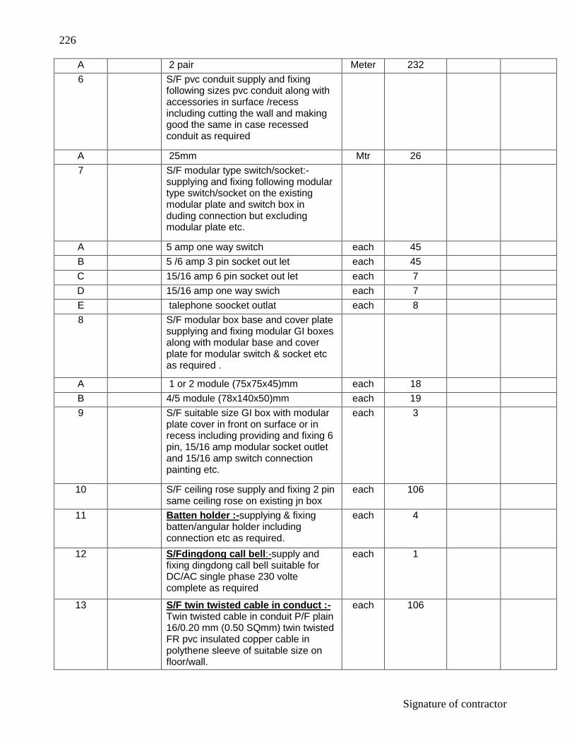
226
Signature of contractor
A 2 pair Meter 232
6 S/F pvc conduit supply and fixing following sizes pvc conduit along with accessories in surface /recess including cutting the wall and making good the same in case recessed conduit as required
A 25mm Mtr 26
7 S/F modular type switch/socket:- supplying and fixing following modular type switch/socket on the existing modular plate and switch box in duding connection but excluding modular plate etc.
A 5 amp one way switch each 45
B 5 /6 amp 3 pin socket out let each 45
C 15/16 amp 6 pin socket out let each 7
D 15/16 amp one way swich each 7
E talephone soocket outlat each 8
8 S/F modular box base and cover plate supplying and fixing modular GI boxes along with modular base and cover plate for modular switch & socket etc as required .
A 1 or 2 module (75x75x45)mm each 18
B 4/5 module (78x140x50)mm each 19
9 S/F suitable size GI box with modular plate cover in front on surface or in recess including providing and fixing 6 pin, 15/16 amp modular socket outlet and 15/16 amp switch connection painting etc.
each 3
10 S/F ceiling rose supply and fixing 2 pin same ceiling rose on existing jn box
each 106
11 Batten holder :-supplying & fixing batten/angular holder including connection etc as required.
each 4
12 S/Fdingdong call bell:-supply and fixing dingdong call bell suitable for DC/AC single phase 230 volte complete as required
each 1
13 S/F twin twisted cable in conduct :-Twin twisted cable in conduit P/F plain 16/0.20 mm (0.50 SQmm) twin twisted FR pvc insulated copper cable in polythene sleeve of suitable size on floor/wall.
each 106

227
Signature of contractor
14 ITC Fluorescent fitting directly on surface:- Installation testing and commissioning of per – wired ,fluoresent fitting of alln type ,complete with all fitting of all type complete with all accessories and tube etc directly on ceiling/wall including connection with 1.5 SQ mm FR pvc insulated copper conductor ,single core cable and earthing etc. as required
each 93
15 S/F 20 amp, 240v SPN industrial type socket out let with 2 pole and earth, metal enclosed plug top along with 20A C' serier P MCB in sheet steel encloser on surfagrears with chained metal sover farthe socket complte with connection etc or as requived.
each 3
16 I.T.C ceiling fan:- installation testing and commissioning of ceiling fan including wiring the down road of standard length (up to 30 cm) with 1.5 SQ.mm FR pvc insulated copper conductor, single core cable as required.
each 44
17 S/f modular electronic fan regulator:- S/F stepped type electronic fan regulator the existing modular plate switch box including connection but excluding modular plate etc.
each 44
18 I.T.C Exhaust fan up to 450mm sweep:- Installation of exhaust fanup to 450 mm. sweep in the existing opening including making the hole to suit the size of the above fan making good the dimage connection testing commissioning etc as required
each 14
19 Fixing louvers shutter for exhaust fan extra for fixing the louvers shutters complete with frame for a exhaust fan of all size.
each 14
20 Supply and fixing TPMCB supply and fixing following way three pole and neutral sheet MCB distribution board 415v on surface/recess complete with tinned copper bus- bar neutral bus- bar earth bar din bar detachable glane plate inter connections phos phatized and power pointed including earthing etc as required (But without MCB/RCCB/isolator )

228
Signature of contractor
A 6way (4+18)double door horizontal type
each 6
21 S/F `C` series MCB :- supply and fixing following 240 volts `C` series MCB suitable for inductive loads of following poles in the existing MCB DB complete with connection testing and commissioning etc as required.
A 6/32 amps S.P each 30
22 S/F four pole MCB Isolator:- supply and fixing following rating four pole 415volt isolator in existing MCB DB complete with connection testing and commissioning etc as required
A 63 amps each 2
B 40 amps each 4
23 S/F TPN RCCB:- supplying and fixing following rating TPN 415V RCCB, having a sensitivity current up to 300 ma in the existing MCB-DB complete with connection testing and commissioning etc as required.
A 63 amps each 1
B 100 amp each 1
24 Supply and fixing blanking plate (sing pe pote in existair Db)
each 32
25 S/F bus bar chamber:- providing and fixing following rating bus bar chamber with 4 strip of suitable size made of copper heavy duty complete with all accessories including connection earthing the body etc as required
A 200 amps each 1
26 S/f MCCB in cubical panel board :- providing and fixing following rating and capacity four pole MCCB in existing capacity cubical panel board including holes in cubical panel making connection etc as required
A 200 amps 35ka fixed thermal setting each 1

229
Signature of contractor
27 Copper earth plate electrode:- Ear thing with copper plate 600mmx600mmx3mm thick including accessories and providing masonry in closer with plate having locking arrangement and watering pipe etc as required with char coal and salt and salt as required
set 2
28 S/L 8SWG Copper wire in ground:- supplying and laying 8 SWG copper wire at 0.5 meter below Gr level for conductor earth electrode including soldering etc as required
Mtr 66
Total Section I -
Section ll (Lighting conductor)
29 Earth plate Electrode:- Earth with GI earth plate 600mmx600mmx6mm thick including accessories encloser with cover plate having locking arrangements and watering pipe etc as required ( but with out – char coal or coke and salt)
set 2
30 Salt/coke for plate earth electrode:- Extra for using saltandRE charcoal far GI or copper plate earth electrode as required
set 2
31 P/F copper lightning conductor finial, made of 25mm dia 300mm long GI tube having single prong at top with 85mm 3mm thick GI base plate including holes etc complete as required
each 2
32 Reverting, sweating and soldering conductor:- reverting & lightring and soldering of GI tape (with another copper) GI tape, base of the final or any other metallic object as required.
each 28
33 P/F GI lightring conductor tape in horizontal run:- Providing and fixing GI tape 20mm x 3mm tick on parapet or surface of wall for lightring conductor complete as required
Mtr 123
34 P/F GI lightring conductor tape in vertical run:- Providing and fixing GI tape 20mm x 3mm tick on parapet or surface of wall for lightring conductor complete as required
Mtr 15

230
Signature of contractor
35 P/F testing joint for GI lightring conductor:- providing and fixing testing joints made of 20mm x 3mm thick GI strip 125mm long with 4 nos GI bolts nuts check nuts and spring washersetc. Complete as required
each 56
36 P/F GI earth tape for lightring conductor:- providing and laying GI tape 32mm x 6mm earth electrode directly ingras Required.
Mtr 16
37 MV cable laying up to 120 Sqmm in Gr :- Laying of one no PVC insulated and PVC sheathed/ XLPE power cable of 1.1KV grade of size not exceeding 120 Sqmm ground including excavation protective covering and re Filling the trench etc as required
Mtr 90
38 P/F danger notice plate providing and fixing MV danger notice plate 200mmv 150mm made of mild steel at least 2 mm thick and vitreous White on both side with inscription in single red color on front side
each 1
39 S/F panel mounted change over switches:- Providing and fixing following capacity 4 pole panel mounted change over switches in existing cubical panel board making connection earthing the body etc as required
A 200A 4 pole each 1
B Supply of 3.5 x 50 Sqmm x LPE/PVCA (Al) cable 1.1KV grade
Mtr 90
40 Supply,installation, testing & commissioning of the following light fixtures complete with lamps, electronic ballasts, lamp holder, starter, starter holder, etc. duly wired complete for use on 240 V single phase 50 Hz AC supply including all accessories required for mounting at surface/recess/wall as mentioned in BOQ and drawings conforming to relavant IP protection and IS codes.
A Supply & Fixing 1 x 28 W fluorescent tube light fitting Make Havells Lamp Type -1x28W FTL T5 ,Odering code -LHIT81128032
66
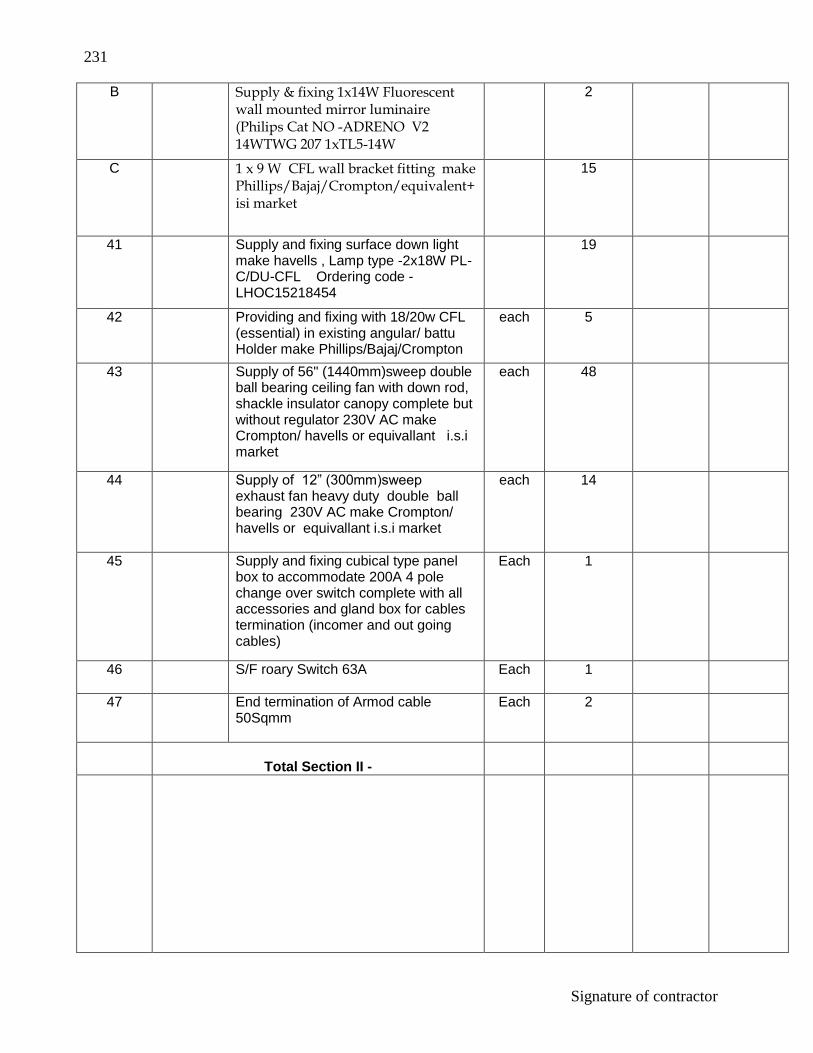
231
Signature of contractor
B Supply & fixing 1x14W Fluorescent wall mounted mirror luminaire (Philips Cat NO -ADRENO V2 14WTWG 207 1xTL5-14W
2
C 1 x 9 W CFL wall bracket fitting make Phillips/Bajaj/Crompton/equivalent+ isi market
15
41 Supply and fixing surface down light make havells , Lamp type -2x18W PL-C/DU-CFL Ordering code -LHOC15218454
19
42 Providing and fixing with 18/20w CFL (essential) in existing angular/ battu Holder make Phillips/Bajaj/Crompton
each 5
43 Supply of 56" (1440mm)sweep double ball bearing ceiling fan with down rod, shackle insulator canopy complete but without regulator 230V AC make Crompton/ havells or equivallant i.s.i market
each 48
44 Supply of 12” (300mm)sweep exhaust fan heavy duty double ball bearing 230V AC make Crompton/ havells or equivallant i.s.i market
each 14
45 Supply and fixing cubical type panel box to accommodate 200A 4 pole change over switch complete with all accessories and gland box for cables termination (incomer and out going cables)
Each 1
46 S/F roary Switch 63A Each 1
47 End termination of Armod cable 50Sqmm
Each 2
Total Section II -

232
Signature of contractor
Section lll -EXTERNAL ELECTRIFICATION
48 Supply ,fabrication and delivery of tubular poles for street light 9 M long (SP-31) with base plate for street light (IS-1161-SP -31)
Each 6
49 Supply of skyline SGP-325 Street light luminaire with press wire die-cast Aluminum housing POT -optics reflector and heat resistant toughened flat glass cover (IP-65)SGP 325-1x1+PITP-150W FG.
Each 6
50 Supply of 4x10Sqmm x LPE PVC Aluminum armoured cabel 1.1 KV grade.
M 200
51 Supply of 63Amp TPN Switch with HRC Fuses.
Each 1
Section lll:-
Total sub head B –
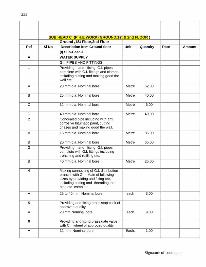
233
Signature of contractor
SUB HEAD C (P.H.E WORK) GROUND,1st & 2nd FLOOR ) Ground ,1St Floor,2nd Floor
Ref Sl No Description Item Ground floor Unit Quantity Rate Amount
(I) Sub-Head-l
A WATER SUPPLY
G.I. PIPES AND FITTINGS
1 Providing and fixing G.I. pipes complete with G.I. fittings and clamps, including cutting and making good the wall etc.
A 20 mm dia. Nominal bore Metre 62.00
B 25 mm dia. Nominal bore Metre 40.00
C 32 mm dia. Nominal bore Metre 6.00
D 40 mm dia. Nominal bore Metre 40.00
2 Concealed pipe including with anti corrosive bitumatic paint, cutting chases and making good the wall.
A 15 mm dia. Nominal bore Metre 85.00
B 20 mm dia. Nominal bore Metre 65.00
3 Providing and fixing G.I. pipes complete with G.I. fittings including trenching and refilling etc.
B 40 mm dia. Nominal bore Metre 25.00
4 Making connecting of G.I. distribution branch with G.I. Main of following sizes by providing and fixing tee, including cutting and threading the pipe etc. complete.
A 25 to 40 mm Nominal bore each 3.00
5 Providing and fixing brass stop cock of approved quality
A 20 mm Nominal bore each 9.00
6 Providing and fixing brass gate valve with C.I. wheel of approved quality.
A 32 mm Nominal bore Each. 1.00

234
Signature of contractor
B 40mm Nominal bore Each. 1.00
7 Providing and fixing metal non-return valve of approved quality.
32 mm nominal bore
Horizontal Each. 1.00
Vertical Each. 1.00
40 mm nominal bore
Horizontal Each. 1.00
Vertical Each. 1.00
8 Painting G.I. pipe and fittings with synthetic enamel white paint over a ready mixed priming coat, both of approved quality for new work.
A 20 mm dia. Nominal bore Metre 12.00
B 25 mm dia. Nominal bore Metre 40.00
C 32 mm dia. Nominal bore Metre 6.00
D 40 mm dia. Nominal bore Metre 40.00
9 Providing and fixing G.I. union in G.I.pipe including cutting and threading the pipe and making long screws etc.
A 20 mm dia. Nominal bore each 4.00
B 25mm dia. Nominal bore each 7.00
D 40 mm dia. Nominal bore each 10.00
10 Providing and placing on terrace (at all floor levels ) polythethylene water storage tank of approved brand and manufacture with cover and suitable locking arrangement and making necessary holes for inlet, outlet and overflow pipes but without fittings and the base support for tank
1000X7=7000 litre 7000.00
11 C.P. BRASS FITTINGS
Providing and fixing C.P brass bib cock of approved quality confirming to IS:8931

235
Signature of contractor
15mm nominal bore Each 26.00
12 Providing and fixing C.P brass long nose bib cock of approved quality confirming to IS standard and weighing not less than810grams.
15mm nominal bore Each 2.00
13 Providing and fixing C.P brass stop cock (concealed) of standard design and of approved make confirming to IS:8931
15mm nominal bore Each 14.00
14 Providing and fixing CP brass shower rose 15 or 20 mm inlet
150 mm diameter Each 6.00
Total sub head –l
(II) Sub-Head-ll
Sanitary Installation
15 Providing and fixing water closet squatting pan (Indian type W.C. pan ) with 100mm sand cast Iron P or S trap, 10 litre low level white P.V.C. flushing cistern with manually controlled device (handle lever) conforming to IS : 7231, with all fittings and fixtures complete including cutting and making good the walls and floors wherever required :
A White vitreous china orissa pattern W.C. pan of size 580 x 440mm with integral type foot rests.
Each 6.00
16 Providing and fixing white vitreous china pedestal type water closet (European type) with seat and lid, 10 litre low level white vitreous china flushing cistern & C.P. flush bend with fittings & C.I.brackets, 40mm flush bend, overflow arrangement with specials of standard make and mosquito proof coupling of approved municipal design complete including painting of fittings and brackets, cutting and making good the walls and floors wherever required :
A W.C. Pan with ISI marked white solid plastic seat and lid.
Each 6.00

236
Signature of contractor
17 Provding and fixing white vitreous china wash basin with C.I./ MS brackets, 15 mm C.P. brass pillar taps, , 32 mm C.P. brass waste of standard pattern, including paintings of fittings and brackets, cutting and making good the .wall wherever required.
fFat back wash basin size 630X450mm with single15mm CP pillar tap
Each 13.00
18
Providing and fixing PTMT Bottle Trap for Wash basin and sink. Bottle trap 31mm single piece moulded with height of 270mm, effective length of tail pipe 260mm from the centre of the waste coupling 77mm breadth with 25mm minimum water seal, weighing not less than 260gms.
Each 13.00
19 Provding and fixing 600X450mm bevelled edge mirror of superior glass complete with 6mm thick hard board ground fixed to wooden cleats with CP brass screws & washers complete.
Each 12.00
20 Provding and fixing 600X120X5 mm glass shelf with edges rounded off supported on anodised aluminium angle frame with CP brass brackets and guard rail complete fixed with 40 mm long screws ,rawl plug etc, complete.
Each 12.00
21 Provding and fixing towel rail complete with brackets fixed to wooden cleats with CP brass screws
600 X 20 mm size Each 7.00
22 Provding and fixing kitchen sink with C.I. brackets, C.P. brass chain with rubber plug,40mm CP brass waste complete , including paintings of fittings and brackets, cutting and making good the .wall wherever required.
white glazed fire clay sink of size 600x450x250mm
Each 3.00
23 Provding and fixing PVC waste pipe for sink & wash basin including PVC waste fittings complete
40 mm dia Each 15.00
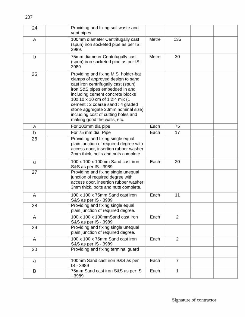
237
Signature of contractor
24 Providing and fixing soil waste and vent pipes
a 100mm diameter Centrifugally cast (spun) iron socketed pipe as per IS: 3989.
Metre 135
b 75mm diameter Centrifugally cast (spun) iron socketed pipe as per IS: 3989.
Metre 30
25 Providing and fixing M.S. holder-bat clamps of approved design to sand cast iron centrifugally cast (spun) iron S&S pipes embedded in and including cement concrete blocks 10x 10 x 10 cm of 1:2:4 mix (1 cement : 2 coarse sand : 4 graded stone aggregate 20mm nominal size) including cost of cutting holes and making good the walls, etc.
a For 100mm dia pipe Each 75
b For 75 mm dia. Pipe Each 17
26 Providing and fixing single equal plain junction of required degree with access door, insertion rubber washer 3mm thick, bolts and nuts complete
a 100 x 100 x 100mm Sand cast iron S&S as per IS - 3989
Each 20
27 Providing and fixing single unequal junction of required degree with access door, insertion rubber washer 3mm thick, bolts and nuts complete.
A 100 x 100 x 75mm Sand cast iron S&S as per IS - 3989
Each 11
28 Providing and fixing single equal plain junction of required degree.
A 100 x 100 x 100mmSand cast iron S&S as per IS - 3989
Each 2
29 Providing and fixing single unequal plain junction of required degree.
A 100 x 100 x 75mm Sand cast iron S&S as per IS - 3989
Each 2
30 Providing and fixing terminal guard
a 100mm Sand cast iron S&S as per IS - 3989
Each 7
B 75mm Sand cast iron S&S as per IS - 3989
Each 1

238
Signature of contractor
31 Providing lead caulked joints to sand cast iron/centrifugally cast (spun) iron pipes and fittings of diameter
A 100mm Each 50
B 75mm Each 20
32 Providing and fixing M.S. stays and clamps for sand cast iron/centrifugally cast (spun) iron pipe of diameter:
A 100mm Each 7
B 75mm Each 1
33 Providing and fixing bend of required degree with access door, insertion rubber washer 3 mm thick, bolts and nuts complete.
100mmSand cast iron S&S as per IS - 3989
Each 19.00
75mmSand cast iron S&S as per IS - 3989
Each 2.00
34 Provding and fixing sand cast iron trap of self cleansing design with sand cast iron screwed down or hinged grating with or without vent arm complete, including cost of cutting and making good the wall and floors.
100mm inlet and 75mm outlet Sand cast iron S&S as per IS: 3989.
Each 19.00
100mm inlet and 100mm outlet Sand cast iron S&S as per IS: 3989.
Each 8.00
35 Providing and fixing collar
100mm Sand cast iron S&S as per IS - 3989
Each 6
75mm Sand cast iron S&S as per IS - 3989
Each 1
36 Painting sand cast iron/centrifugally cast (spun)soil, waste vent pipes and fittings with paint of any colour such as match with adjacent wall colour etc., over a coat of primer (of approved quality) for new work.
100mm dia pipe Metre 135
75mm dia pipe Metre 30
37 Providing and fixing stainless steel kitchen sink as per IS:13983 with C.I. Brackets and stainless steel plug 40mm including painting of fittings and brackets, cutting and making good the walls wherever required.
Kitchen sink without drain board. 610x510 bowl depth 200mm
Each 3

239
Signature of contractor
38 Providing and fixing P.V.C. waste pipe for sink or wash basin including P.V.C. waste fittings complete
40mm dia Flexible pipe Each 3
TOTAL SUB HEAD -ll
(III) Sub-Head-lll
C DRAINAGE
39 Providing and laying non -pressure NP2 class R.C.C. pipes with collars jointed with stiff mixture of cement mortar in the proportion of 1:2 including testing of joints etc.
150 mm dia R.C.C. pipe Metr. 75.00
40 Constructing brick masonary manhole in cement mortar 1:4 (1 cement, 4 coarse sand.) R.C.C. top slab with1:2:4 mix(1 cement, 2 coars e sand, 4 graded stone aggregate 20 mm nominal size) foundation cocrete 1:4:8 mix (1cement, 4 coarse sand, 8 graded stone aggregate 40 mm nominal size.) inside plastering 12 mm thick with cement mortar 1:3 (1 cement, 3 coarse sand.) finished with floating coat of neat cement and making channels in cement concrete 1:2:4. finished with floating coat of neat cement complete as per standard design.
a Inside size 90x80cm and 45 cm deep including C.I. cover with frame ( light duty) 455x610 mm internal diamension tatal weight of cover and fram to be not less than 38 kg (weight of cover23 kg and weight of frame 15 kg )
With F.P.S. bricks with class designation 75
Each 15.00
b Inside size 120x90cm and 90 cm deep including C.I. cover with frame (medium duty) 500mm internal diameter total weight of cover and fram to be not less than 116 kg (weight of cover 58kg and weight of frame 58 kg )
With F.P.S. bricks with class designation 75
Each 2.00
TOTAL SUB HEAD –lll

240
Signature of contractor
D Sub-Head-lV (SEPTIC TANK )
Septic tank( liquid dimension-4.8X1.8X1.5 cu-m) ,1 Nos.
41 Earthwork in excavation in foundation trenches or drains including dressing of sidesand ramming of bottoms,lift upto 1.5m,including getting out the excavated soil and disposal of surplus excavated as directed within a lead of 50m
All kind of soil Cum 59.20
42 Supplying and filling in plinth with local sand and under floors including watering,ramming consolidating and dressing complete
Cum 2.38
43 Providing and laying in position concrete of specified grade excluding the cost of centring and shuttering all work upto plinth level
44 1:2:4(1cement:2 corse sand:4 graded stone aggregate 20mm nominal size
Cum 2.38
45 Brick work with bricks of class designation 100A in foundations and plinth in
Cement morter 1:6(1 cement : 6 corse sand)
Cum 10.72
46 12 mm cement plaster of mix
1:4(1 cement : 4 corse sand) Sqm. 100.61
47 Neat cement punning Sqm. 100.61
48 Brick on edge flooring bricks of class designation 100a including cement slurry etc. complete in cement morter
1:6(1 cement : 6 corse sand) Sqm. 16.56

241
Signature of contractor
49 Reinforced cement concrete work in beams,suspended floors roofs,having slope upto 15, landing,balconies, shelves,chajjas,lintal,bends,plain window sills stair case,and spiral staircases up to floor five level excluding the cost of centering,shuttering,finishing and reinforcement with 1:2:4
Cum 3.38
50 Centring and shuttering including strutting propping etc. and removal of form for
Suspended floors ,roofs,landings,balconies and access platform
Sqm. 15.28
51 Lintels,beams,plinth bams,griders,bressumers and cantilivers
Sqm. 2.25
52 Columns,pillars,piers,abutments,posts and struts
Sqm. 6.00
53 Supplying and fixing C.I cover without frame for manholes:
500 mm diameter C.I cover (medium duty) the weiht of he cover to be not less than 58 kg.
Each 2.00
54 Providing M.S foot rests including fixing in septic tank with 20 x 20 x 10 cm cement concrete blocks 1:3:6 ( 1 cement: 3 coarse sand: 6 graded stone aggregate 20mm nominal size) as per standard design:
With 20 x 20 mm square bar Each 18.00
55 Providing and fixing s.W intercepting trap in manholes with stiff mixture of cement mortar 1:1(1 cement: 1 fine sand) including testing of joints etc. complete.
150 mm dia Each 2.00
TOTAL SUB HEAD -lV
(IV) Sub-Head-E
RAIN WATER PIPES AND FITTINGS

242
Signature of contractor
56 Providing and fixing on wall face unplasticised Rigid PVC rain water pipes conforming to IS:13592 Type A including jointing with seal ring conforming to IS:5382 leaving 10mm gap for thermal expansion.
(i) Single socketed pipes
a 110 mm diameter Meter 80
b 75 mm diameter Meter 20
57 Providing and fixing on wall face unplasticised - PVC moulded fittings/accessories for unplasticised Rigid PVC rain water pipes conforming to IS:13592 Type A including jointing with seal ring conforming to IS: 5382 leaving 10mm gap for thermal expansion.
(i) Shoe (Plain)
a 110mm Shoe Each 8
b 75mm Shoe Each 6
(ii) Single Tee without door
a 75x75x75mm Each 14
(iii) Bend 87.5°
a 110mm Bend Each 8
b 75mm Bend Each 6
58 Providing and fixing unplasticised - PVC pipe clips of approved design to unplasticised - PVC rain water pipes by means of 50 x 50 x 50mm hard wood plugs, screwed with M.S. screws of required length including cutting brick work and fixing in cement mortar 1:4 (1 cement : 4 coarse sand) and making good the wall etc. complete.
a 110mm Each 44
b 75mm Each 13
59 Providing and fixing to the inlet mouth of rain water pipe cast iron grating 15 cm diameter and weighing not less than 440 grams.
Each 14
TOTAL SUB HEAD –lV
(V) Sub-Head-V
E WATER SUPPLY

243
Signature of contractor
60 Constructing masonry chamber 30x30x50 cm, inside with 75 class disignation brick work in cement mortar 1:5 (1 cement :5 fine sand) for stop cock, with C.I. surface box 100x100x75 mm with hinged cover fixed in cement concrete slab 1:2:4 mix (1 cement :3 coarsesand :4 graded stone aggregate 20 mm nominal size) necessary sand :4 draded stone aggregate 20 mm nominal :5 fine sand :10 graded stone aggregate 40mm nominal size) and inside plastering with cement mortar 1:3 (1 cement :3 coarse sand) 12 mm thick finished with a floating coat of neat cement complete as per standard disign.
With F.P.S. bricks Each 1.00
TOTAL SUB HEAD –V
(VII) Sub-Head-Vl
G DRAINAGE
61 Making soak pit 2.5 m diameter 3.0 meter deep with 45x45 cm dry brick honey comb shaft with brick of class designation 75 and S.W. drain pipe 100 mm diameter, 1.8 m long complete as per standard design.
With F.P.S. bricks Each 1.00
62 Providing and fixing square mouth SW gully trap grade A complete with CI grating brick masonry chamber with water tight CI cover with frame of 300X300mm size(inside) the wt. of cover to be not less than4.50kg. And frame to not less than 2.70 kg. as/standard design
150x100mmsize p type
With F.P.S. bricks designation 75 Each 1.00

244
Signature of contractor
63 Constructing brick masonry road gully chamber 45X45X77.5 cm with bricks of class designation 75 in cement mortar 1:4 including 500 X 450 mm pre cast RCC vertical grating complete as per standard design
with FPS bricks each 1
TOTAL SUB HEAD -Vl
H SUB HEADVLL (TUBEWELL)
64 Providing all materials labour for drilling by reverse Rotary rig machine for following diameter of bore hole in all kinds of soil mixed with kankar, sand and stone including providing sample box and collection strata sample of every 10'-0" depth of drilling for accortaining proper equiler for completing 300mmx200mm dia high yielding tube well complete as per P.H.E.D. spicifications
250 mm dia bore from 0 to 30 mtrs Mtrs. 30
250 mm dia bore from 30 to 60 mtrs Mtrs. 30
250 mm dia bore from 60 to 90 mtrs Mtrs. 30
250 mm dia bore from 90 to 120 mtrs Mtrs. 30
65 Supplying all materials such as following sizes of PVC pipe with socket and providing equipment and labour for lowering the following pipe and cutting the pipe to required size as per approved assly and strata chart as required all complete as per direction of E/I.
110 mm dia PVC. Pipe mtrs. Mtrs. 30
75 mm dia PVC. Pipe mtrs. Mtrs. 45
75 mm dia PVC.slotted Pipe mtrs. Mtrs. 30
66 Supplying the following fitting and fixing the same in position as per approved lowering assembly and strata chart including providing all equipment on process of lowering the assly etc.all complete as per direction of E/I.
110X 75 mm dia PVC Reducer. Each 1
75 mm dia PVC. Well plug. Each 1
Solvent Cement. Kg 1
75 mm dia steed cap Each 1
GI wire 14 nos Kg 8

245
Signature of contractor
67 Supplying all materials labour and tools for fitting tube well with pea graved of dalbhumgarh of size 4 mm to 8 mm including carriage, washing and placing the same in position around the tube well as per direction of E/I. Market Rate
cft 200
68 Supplying all equipments, tools and labour and developing the tube well by air compressor for continuous 8 hrs. till sand free discharge of tube well as various depth all complete as per direction of E/I. Market Rate
Hrs 8
69 Transportation cost for rig machine and other accessories materials and equipments including development unit etc. To tube well site till complete of work and returning back etc. all complete.Market rate
L.S. 1
70 Supplying all materials and labour for arrangement for additional water required during drilling period. Market rate.
L.S. 1
71 Establishment of -2HP of submersible pump set (detail attchhed)
each 1
Total Vll
Total Sub head C –
CIVIL ITEMS SUB HEAD D (SITE DEVELOPMENT & BOUNDARY WALL)
Description Unit Quantity Rate Amount
ROAD & PAVING WORK
1 Earth work in excavation by mechanical means (Hydraulic excavator) / manual means over areas (exceeding 30cm in depth. 1.5m in width as well as 10 sqm on plan) including disposal of excavated earth, lead upto 50m and lift upto 1.5m, disposed earth to be levelled and neatly dressed.
All kind of soil Cum 50.0
2 Filling available excavated earth (excluding rock) in trenches, plinth, sides of foundations etc. in layers not exceeding 20cm in depth, consolidating each deposited layer by ramming and watering, lead up to 50 m and lift upto 1.5 m.
All kind of soil cum 950.0

246
Signature of contractor
3 Banking excavated earth in layers not exceeding 20 cm. in depth, reaking clods, watering, rolling each layer with ½ tonne roller, or wooden or steel rammers, and rolling every 3rd and top-most layer with power roller of minimum 8 tonnes and dressing up,
All kind of soil cum 150
4 Providing & laying in position cement concrete of specified grade excluding the cost of centring and shuttering -All works upto plinth level:
1:3:6 (1 cement: 3 coarse sand: 6 graded stone aggregate 20 mm nominal size)
cum 8
5 Earth work in rough excavation , banking excavated earth in layer notexceeding 20 cm in depth , breaking clods watering , rolling each layer with 1/2 tonne roller or wooden or steel rammers and rolling every 3rd and top-most layer with power roller of minimum 8 tonnes and dressing up in embankments for roads, flood banks , marginal banks and guide banks or filling up ground depressions. lead upto 50 m and lift upto 1.5m.
All Kinds of soil cum 105
6 Construction of granular sub-base by providing close graded Material conforming to specifications, mixing in a mechanical mix plant at OMC, carriage of mixed material by tippers to work site, for all leads & lifts, spreading in uniform layers of specified
cum 8.25
7 Providing and laying 60mm thick factory made cement concrete interlocking paver block of M -30 grade of approved shape & Size made by block making machine with strong vibratory compaction and of approved size and design/ shape laid in required colour and pattern over and including 50mm thick compacted bed of course sand, filling the joints with coarse sand etc. all complete as per the direction of Engineer-in-charge.
Sqm 225

247
Signature of contractor
8 Providing and laying 60mm thick factory made cement concrete interlocking grass paver block of M 30 grade approved shape & Size made by clock making machine with strong vibratory compaction and of approoved size and design/shape laid in required colour & pattern over and including 50mm thick compacted bed of course sand, filling the joints with course sand etc. all complete as per the direction of Engineer-in-Charge
Sqm 400
9 Providing and faying cement concreate in kerbs, steps and the like at or near ground level excluding the cost of centring, shuttering and finishing.
1:3:6 (1 Cement:3 coarse sand:6 graded stone aggregate 20 mm nominal size)
cum 10
10 Brick work with bricks of class designation 100B in foundations and plinth in ::
Cement mortar 1:6 (1 cement : 6 coarse sand)
Cum 76
12 mm cement plaster of mix : 1:6 (1 cement: 6 fine sand)
sqm 142.5
Applying one coat of white cement primer of approved brand and manufacture on exterior wall surface:
sqm 57
Finishing walls with water proofing cement paint(Snowcem) of approve brand and manufacture and of required shade to give an even shade new work (Three or more coat).
sqm 57
Total road work
Boundary wall and gate
11 Earth work in excavation by mechanical means (Hydraulic excavator) / manual means in foundation trenches or drains (not exceeding 1.5 m in width or 10 sqm on plan) including dressing of sides and ramming of bottoms, lift upto 1.5 m, including getting out
All kind of soil Cum 210

248
Signature of contractor
12 Filling available excavated earth (excluding rock) in trenches, plinth, sides of foundations etc. in layers not exceeding 20cm in depth, consolidating each deposited layer by ramming and watering, lead up to 50 m and lift upto 1.5 m.
Cum 120
13 Providing & laying in position cement concrete of specified grade excluding the cost of centring and shuttering -All works upto plinth level:
1:3:6 (1 cement: 3 coarse sand: 6 graded stone aggregate 20 mm nominal size)
cum 26
14 Providing and laying in position machine batched and machine mixed design mix M-25 grade cement concrete for reinforced cement concrete work, using cement content as per approved design mix, including pumping of concrete to site of laying but excluding th
(Note :- Cement content considered in this item is @ 330 kg/cum. Excess/less cement used as per design mix is payable/recoverable separately).
All works upto plinth level. cum 6.5
All works above plinth level upto Roof Floor.
cum 1.5
Walls columns, pillars, posts cind struts
cum 11
Beams, planth beams, girders, bressumers, contilevers,Suspended floors lintels roofs and staircases includingspiral staircases, shelves etc.
cum 27
15 Steel reinforcement for R.C.C. work including straightening, cutting, bending, placing in position and binding all complete upto plinth level.
Thermo-Mechanically Treated bars TMTC-500-6mm dia.
kg 510
Thermo-Mechanically Treated bars TMTC-500-8mm dia.
kg 800
Thermo-Mechanically Treated bars TMTC-500-10mm dia.
kg 1110
Thermo-Mechanically Treated bars TMTC-500-12mm dia.
kg 1050

249
Signature of contractor
16 Centering & shuttering including strutting, propping etc.& removal of form (staging height upto 4.2m) for:
Foundations, footings, bases of columns etc. for mass concrete.
sqm 325
Columns, pillars, piers, abutments, posts & struts.
sqm 276
Suspended floors, roofs, landings, balconies & access plateform.
sqm 15
Lintels, beams, plinth beams, girders, bressumers & cantilevers.
sqm 3
17 Brick work with common burnt clay F.P.S. (non modular) bricks of class designation 7.5 in superstructure above plinth level up to floor V level in all shapes and sizes in : Cement mortar 1:6 (1 cement : 6 coarse sand)
cum 98
18 Making plinth protection 50mm thick of cement concrete 1:3:6 (1 cement :3 coarse sand : 6 graded stone aggregate 20 mm nominal size) over 75mm thick bed of dry brick ballast 40 mm nominal size, well rammed and consolidated and grouted with fine sand inclu
sqm 15
19 12 mm cement plaster of mix : 1:6 (1 cement: 6 fine sand)
sqm 1325
20 6 mm cement plaster of mix : 1: 3 (1 cement: 3 fine sand)
sqm 20
21 Brick Flat soiling :- Providing designation 100 B one brick flat soling joints filled with local sand including cost of watering, taxes, royalty all complete as per building specification and direction of E/l,
sqm 15.0
22 P.C.C Flooring:- 40mm Th cement concrete flooring 1:2:4(1Cement:2 Coarse:4 Grade stone aggregate)finished with a floating coat of neat cement including cement slurry etc.
sqm 15
23 Skirting :- 18mm Th Cement plaster skirting (up to 15 Cm height) with cement mortar 1:3(1Cement : 3 coarse sand ) finished with a floating coat of neat cement .
sqm 8

250
Signature of contractor
24 Door chowkhat :-Providing and fixing pressed steel door frame confirming IS code 351 manufactured from commerical mild steel sheet of 1.25 mm thickness including hinges, jamb, lock jamb, bead and if required angle threshold of mild steel angle of section 50 x 25 mm or base ties of 1.25mm pressed mild steel welded or rigidly fixed together by . mechnical means, adjustable lugs with split end tail to each jamb including steel butt hinges 2.5 mm thick with mortar guards, lock strike-plate and shock absorbers as specified and applying a coat of approved steel primer after pre-treatment of the surface as directed by Engineer-in-charge: Profile C
meter 5.5
25 Providing and fixing 1mm thick M.S. sheet door with frame of 40x40x6mm angle iron and 3mm M.S. gusset plates at the junctions and corners, all necessary fittings complete, including applying a priming coat of approved steel primer.Using M.S. angels 40x40
sqm 2.1
26 Providing and fixing M.S. grills of requirement pattern in frames of windows etc. with M.S. flats bars 5mm Th & 20mm wide or 10mm x 10mm square bars @ 100mm C/C Vertical /horizontal etc.all complete, fixed to openings/wooden frames with rawl plugs screws etc.
kg 550

251
Signature of contractor
27 Steel glazed window :- Providing and fixing steel glazed windows and ventilatrs of standard rolled steel sections, joints mitered and welded with 15x3 mm lugs 10 cm long with steel lugs embedded in cement concrete blocks 15x10x10 cm of 1:3:6(1 cement: 3 coarse sand : 6 graded stone aggregate 20 mm nominal size) or with woodenplugs and screws or rawl plugs and screws or with fixing clips or with bolts and nuts as required, including providing and fixing of glass panes with glazing clips and special metal-sash putty of approved make complete including applying a priming coat of approved steel primer; excluding the cost of metal beading and other fitting except necessary hinges or pivots as required.
Sqm 3
28 Providing and fixing M.S.fan clamp type 1 of 16 mm dia.M.S. bar bent to shape with hooked ends in R.C.C slabs during laying including painting the exposed portion of loop,all as per standard design complete.
each 1
29 Providing and fixing circular cast iron box for ceiling fan clamp 140 mm internal dia, 73 mm height, 5 mm thick rim bottom and top lids, 1.5 mm thick M.S sheet with its top surface hacked for proper bonding top lid shall be screwed into the cast iron box by means of 3.3 mm dia round headed screws, one ;pcf at the corners. Clamps shall be made of 12 mm dia M.S. bar bent to shape as per standard drawing.
each 1
30 Applying one coat of white cement primer of approved brand and manufacture on exterior wall surface:
sqm 1350
31 Finishing walls with water proofing cement paint(Snowcem) of approve brand and manufacture and of required shade to give an even shade new work (Three or more coat).
sqm 1350

252
Signature of contractor
32 Distempering with dry distemper of approved brand and manufacture (Ashian/Berger/) two or more coats and of required shade on new work ,over and including primimn coat of whiting to given an even shade.
sqm 30
33 With ready mixed zinc chromate yellow primer of approved brand and manufacture on steel galvanized iron/steel works
sqm 15
34 Painting with synthetic enamel paint of approved brand and manufacture with enamel putty in all shades to give an even shade New steel work (two or more coats)
sqm 15
35 Providing and fixing concertina coil fencing with punched tape concertina coil 600 mm dia 10 metre openable length ( total length 90 m) having 50 nos rounds per 6 metre length, upto 3 m height of wall with existing angle iron 'Y' shaped placed 2.4 m or 3.
Rmt 270
TOTAL OF BOUNDARY WALL & GATE HOUSE WORK CARRIED OVER TO SUMMARY OF CIVIL WORKS
Total Sub head D :- for boundary wall & Site development -
TOTAL SUB HEAD (A+B+C+D)
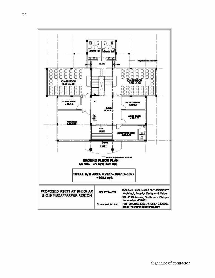
253
Signature of contractor

254
Signature of contractor

255
Signature of contractor