hat creek project - em.gov.bc.ca · pdf filehat creek project - alternative “b”...
TRANSCRIPT

I
BRITISH COLUMB m
HAT
I A HYDRO AND POWER AUTHOR
CREEK PROJECT
ITY
a
Disposal Study - November 1978, Revisions December 1980. Integ-Ebasco - Hat Creek Project - Alternative “B” Ash
ENVIRONMENTAL IMPACT STATEMENT REFERENCE NUMBER: 38 .#
B. C . HYDRO & POWER AUTHORITY
HAT CREEK PROJECT
ALTERNATIVE ' 6 ' ASH DISPOSAL STUDY
Integ-Ebasco Vancouver, B.C.
November 1978 Rev. 1 - January 19713
Rev. 2 - December 19130 Rev. 3 - A p r i l 1981

I integ-ebasco
ALTERNATIVE 'B' ASH DISPOSAL SnJDY
TABLE OF CONTENTS
A . summary
1. Introduction 2 . Purpose 3 . Scope 3 . Results and Conclusions 5 . Recommendations
B. Discussion 1. Composition of Report 2 . Brief Description of Base Scheme and Alternative 'A'
2 . 1 Base Scheme 2 . 2 Alternative ' A '
3 . Description of Alternative 'B' 3.1 Ash Handling in Power Plant Area 3 . 2 Ash Transportation, Distribution, Compaction and
Disposal Area Reclamation 3 . 3 Makeup Water Pumphouse and Pipeline 3 . 4 Water Quality 3 . 5 Water Management
4 . Economic Analysis
C. Reconciliation and Comparison of Present Estimate with May 1978 Schemes
D. List of References

I1
A l t e r n a t i v e ' B ' Ash Disposal Study
A l t e r n a t i v e ' B ' Sketch No. BCH-0064
SK 147 Rev. A
SK 148 Rev. A
SK 149
SK 150
SK 151 Rev. A
SK 153
SK 170
SK 154
SK 155
SK 156 Rev. A
SK 157 Rev. A
SK 158 Rev. A
SK 159 Rev. A
SK 160 Rev. A
A l t e r n a t i v e ' A ' Sketch No. BCI1:0064
SK 161
LIST OF DRAWINGS
T i t l e - Continuous Bottom Ash Dry Removal System - Flow Diagram
Fly Ash Removal System - Flow Diagram
Bottom Ash Drag Bar Conveyor - General Arrangement
Ash Disposal Area - Method o f Ash Spreading
Ash Disposal Area - S i t e P l a n
Not used.
Powerplant Water Balance Cases I A , I B , I I A , IIB
Not used.
Power P l a n t - P l o t P l a n
Makeup Water Pumphouse
Makeup Water Pumphouse
Makeup Water Pumphouse
F l y Ash Air S l i d e System - Flow Diagram
F l y Ash Air E j e c t o r System - Flow Diagram
integ-ebasco
Location - Following Page Number
B-17
B-17
8-17
B-29
Back Cover
B-47
B-17
B-32
B-32
8-32
B-17
B-17
A l t e r n a t i v e ' A ' - Ash Handling Scheme - System Diagram
Rev. 2
8-3

integ-ebasco
I11
LIST OF DRAWINGS
Base Scheme Drawing No.
BCH-0064-Ml14, Rev. B Flow Diagram F l y Ash Handling
Location - Fol lod ing - T i t l e Page Number -
System B- 3
BCH-0064-Ml15, Rev. B Flow Diagram Bottom Ash Handling System B-3
604H-Z31-X020001 Rev. 2 Project Layout Map B-3
Rev. 2

I A- 1 integ-ebasco
Alternative 'B' Ash Disposal Study
A . SUMMARY
1. Introduction During 1977 Integ-Ebasco studied several alternative ash handling and disposal schemes based on proven North American equipment and practice. A wet ash sluicing scheme for both bottom ash and fly ash was recommend- ed with a disposal pond in Upper Medicine Creek Valley. In this study the above scheme is referred as "Base Scheme". Contingent dry disposal schemes were selected should it be discovered that leaching problems in the Upper Hat Creek Valley preclude this as a site for an ash disposal pond on economic grounds. 411 the dry ash and wet ash handling schemes were based on intermittent sluicing of bottom ash from the boilers. For dry ash schemes dewatering bins or intermediate ponds were envisioned for bottom ash "drying" prior to its final disposal.
In conjunction with any one of the above schemes a makeup water reservoir
relatively close to the SE corner of the power plant was planned with water supplied from the Thompson River only.
A further study performed by Integ-Ebasco in May 1978 showed the economic and technical advantages of continuous removal of bottom ash from the boiler by means of a drag bar conveyor - a method frequently used in Continental European power stations. The scope of that study did not, however. include alternative ash handling and disposal methods,
In July 1978, B.C. Hydro requested that Integ-Ebasco study another alter- native dry ash handling scheme in conjunction with a relocation of the makeup water reservoir. The request originated from an analysis of the two Integ-Ebasco studies referenced above, along with work performed by B.C. Hydro on potential dry ash disposal sites and other aspects of the project. This analysis indicated an{ apparent overall saving, particuhrly in the costs of the "off site" facilities, through dry ash disposal and by utilizing Medicine Creek water to supplement the makeup water supply from the Thompson River. The study was n o t t o limit the power plant water management to effect zero liquid discharge and was titled "Alternative 'B' Ash Disposal System". In contrast to previous schemes for ash disposal

A- 2 integ-ebasco
A l t e r n a t i v e 'B' Ash Disposal Study
t h e r e q u e s t f o r t h e new s t u d y d i d n o t r e q u i r e f l y a s h and bottom ash
s t o r a g e t o b e s e g r e g a t e d f o r p o s s i b l e f u t u r e use o r commercial s a l e .
2 . Purpose
The purpose of t h i s s t u d y i s : - To d e v e l o p a n a l t e r n a t i v e a s h h a n d l i n g scheme based on the use of
drag bar conveyors for bot tom ash removal and on d i s p o s a l o f d r y
f l y a s h and bottom ash, along with mine w a s t e m a t e r i a l , i n Mid
Medicine Creek.
- To r e l o c a t e t h e makeup water r e s e r v o i r t o Upper Nedicine Creek and
to eva lua te t he u se o f Med ic ine Creek wa te r fo r power p l a n t consump-
t i o n p u r p o s e s .
- To perform a comparat ive technical and economic evaluat ion of the ne',\i
A l t e r n a t i v e 'B' w i t h t h e p r e s e n t d e s i g n "Base" a s h s l u i c i n g a n d wet d i s p o s a l scheme and i t s m o d i f i c a t i o n e n t i t l e d A l t e r n a t i v e ' A ' .
3 . Scope The scope of t he s tudy r equ i r ed In t eg -Ebasco to :
3 .1
3 . 2
3 . 3
3 . 4
3 . 5
Recommend a bottom ash removal system (incorporating bottom
ash d rag ba r conveyors ) , a f ly ash removal system and a
d ry a sh t r anspor t a t ion sys t em f rom the power p l a n t s i t e t o
Mid Medicine Creek disposal a r ea .
Recommend a s y s t e m o f a s h d i s p o s a l i n d r y f o r m i n a s p e c i f i c
s e c t i o n o f &lid Medicine Creek Valley complete with reveget-
a t i o n and reclamation methods for the area.
De te rmine t he f i n i shed su r f ace conf igu ra t ion o f t he a sh
and mine waste disposal area.
Recommend a makeup wa te r i n t ake and pumphouse a t t h e r e -
l o c a t e d r e s e r v o i r b a s e d on extreme water l e v e l s g i v e n by
B . C . Hydro.
E s t i m a t e t h e v a r y i n g w a t e r q u a l i t y i n t h e r e s e r v o i r d u e
t o mixing of Medicine Creek runoff and Thompson River
wa te r . S tudy t he e f f ec t on the power p l a n t o f a d i f f e r e n t

A- 3
Alternative 'B' Ash Disposal Study
integ-ebasco
3.6
3 . 7
3.8
3 . 9
makeup water quality due to the miking of Nedicine Creek runoff water and Thompson River water in the reservoir and due to the ash removal/transportation/disposal avstem -.
in this report. Recommend a method of controlling seepage and direct precipitation runoff from the ash disposal area for the first 15 years of plant operation (prior to mine waste disposal in Medicine Creek Valley). Determine any imbalance of water resulting from water management of the power plant and ensure that the quality of water discharged by the power plant be not lower than that of cooling tower blowdown. Develop the major features and economics of a modified wet "base" scheme (Alternative 'A') which should utilize: - drag bar conveyors for continuous bottom ash removal
(as opposed to intermittent removal in Base Scheme) - Medicine Creek water entering the ash disposal pond
to supplement Thompson River makeup. Provide a comparative technical and economic evaluation (capital and operating costs) of the new Alternative 'B' Dry Ash Disposal Scheme and wet disposal schemes ("Base" and Alternative ' A ' ) .
4. Results and Conclusions - ~.
This section addresses and provides results for all the items listed in the scope of work (Section 3 ) . It concludes that, based on the information currently available, Alternative 'B' is technically feasible and economic- ally attractive in both capital and operating costs.
Referring to the scope of work listed in Section 3 the results and conclu- sions of the individual items are as follows:
4.1 A dry system using pressurized air to convey fly ash to silos and then using two 100% capacity belt conveyors to

A-J integ-ebasco
A l t e r n a t i v e ' B ' Ash Disposal Study
t r a n s p o r t a m i x t u r e o f c o n d i t i o n e d f l y a s h from t h e s i l o s
and damp bot tom ash to Mid Medicine Creek Valley appears
t o be the p re fe r r ed sys t em. However, manufacturers should
be a l lowed to b id o ther p roven sys tems.
Drag bar conveyors with above ground interconnect ing and
c o l l e c t i n g b e l t c o n v e y o r s are the p re fe r r ed bo t tom a sh
removal system.
4 . 2 Mixed bottom and f l y a s h s h o u l d b e s t a c k e d i n i n c l i n e d ,
compacted t i e r s i n t h e v a l l e y u s i n g a system of movable/
mobile conveyors and bulldozers. The i n c l i n e d t i e r s would
a l t e r n a t e between ash produced in freezing and nonfreezing
cond i t ions t o p rov ide area s t a b i l i t y f o r any ash not
compacted f u l l y d u e t o i t s f rozen wa te r con ten t . A system
of in t e rposed l aye r s o f bo t tom a sh and f l y a sh shou ld be
p r o v i d e d f o r d r a i n a g e c o u r s e s f o r a s h a n d r e s e r v o i r w a t e r
s e e p a g e a n d d i r e c t p r e c i p i t a t i o n . F i n i s h e d a s h s u r f a c e s
shou ld be r eached a s r ap id ly a s p rac t i ca l t o enab le t opso i l
t o be placed and seeded fo r educe dus t ing and f o r r e c l a m a -
t i o n p u r p o s e s .
Rec la iming t he d ry a sh d i sposa l area i n A l t e r n a t i v e ' B ' i s g r e a t l y s i m p l i f i e d i n comparison with the ash ponds of the
base scheme and A l t e r n a t i v e ' .A'.
4 .3 The f i n i s h e d s u r f a c e c o n f i g u r a t i o n s h o u l d g e n e r a l l y s l o p e
t o t h e s o u t h and west,as shown on Drawing BCH 0064 SK 151.
4 .4 The proposed makeup water pumphouse and i n t a k e c o n f i g u r a t i o n
i n t h e makeup r e s e r v o i r i s shown on Drawings BCH 0064 SKl56,
157 and 158. M a t e r i a l e x c a v a t e d i n b u i l d i n g t h i s s t r u c t u r e
would be used i n c o n s t r u c t i o n o f t h e r e s e r v o i r dam. A s i n g l e
makeup w a t e r p i p e l i n e i s p roposed a long t he rou te i nd ica t ed
on Drawing BCH 0064 Si; 151.

A-5 integ-ebasco
A l t e r n a t i v e ' B ' Ash Disposal Study
4.5 Rese rvo i r water q u a l i t y was d e v e l o p e d f o r s e v e r a l p o s s i b l e
Medicine Creek and Thompson River water input combinations
and took into account the increasing water consumption of
t h e s t a t i o n a s t h e u n i t s a r e b r o u g h t i n t o s e r v i c e . The
c a l c u l a t i o n s show t h e w a t e r q u a l i t y to be v a r i a b l e and
i n f e r i o r t o t h a t of t h e Base Scheme u t i l i z i n g Thompson
River water only. Power plant water balances were prepared
f o r t h e s e d i f f e r e n t o p e r a t i n g c o n d i t i o n s . The c i r c u l a t i n g
water system maximum c y c l e s of concen t r a t ion , blowdown
rate and acid dosing, the method of economizer ash disposal,
t h e b o i l e r makeup water treatment system, the methods of
d i s p o s a l of b o i l e r c l e a n i n g w a s t e s and c o a l s t o r a g e a r e a
runoff would be a f f e c t e d by the change in water q u a l i t y .
However, t he impac t i n gene ra l is n o t d r a s t i c .
4.6 P r e c i p i t a t i o n on t h e a s h d i s p o s a l a r e a and a s h p i l e
seepage would be r e t a i n e d by a sma l l berm i n t h e v a l l e y .
The co l lec ted water would be pumped to the power p l a n t
and coa l s to rage runof f wa te r r e t en t ion pond. This pond
would s e r v e a s a source of w a t e r f o r damping down the a sh
d e p o s i t s and would a l s o h a v e p r o v i s i o n f o r d r a i n i n g and
o v e r f l o w i n g v i a t h e n o r t h c u t o f f c a n a l t o t h e r e s e n r o i r .
4.7 For A l t e rna t ive 'B' the ne t imbalance of wa te r r ep resen t s
an excess f rom the power p l a n t of 0.6 11s t o 21.1 11s of
coo l ing tower blowdown water and of qual i ty as indica ted
by t h e v a r i o u s water balances generated (Drawings BCH
0064 SK 153 and 154 and Table 4 ) . For average meteorolo-
g i c a l c o n d i t i o n s and l i f e t i m e a v e r a g e p l a n t c a p a c i t y
f a c t o r of 0.65 ( c a s e 4 of t h i s s t u d y ) t h e e x c e s s c o o l i n g
tower blowdown amounted t o 6 . 1 l i s . As i n s t r u c t e d by
B.C. Hydro no al1owanr.e was made a t t h i s s t a g e f o r any
c o s t s a r i s i n g d u e t o d i s p o s a l of excess power p i n t
w a t e r . S e v e r a l p o s s i b l i l i t i e s a r e c o n s i d e r e d by B.C.
Hydro , i nc lud ing u t i l i za t ion fo r coa l wash ing , mine was t e
d i s p o s a l , a g r i c u l t u r e n e e d s , e t c . , - .
Rev. 1
R 1

A-6 integ-ebasco
A l t e r n a t i v e ' B ' Ash Disposal Study
4 .8 Poten t ia l f reez ing problems were cons idered i n t he s tudy
on the fol lowing equipment andlor systems:
- Ash Conveying
- Ash Compaction
- Ash P i l e Runoff
- Makeup Water Pumphouse
I t i s a n t i c i p a t e d t h a t no ser ious t echnica l p roblems due
t o t h e s e v e r e w i n t e r c o n d i t i o n s w i l l be met if prope r
a t t e n t i o n would be p a i d t o o p e r a t i o n and maintenance
procedures , espec ia l ly dur ing shutdown and s t a r t - u p o p e r a t i o n s .
Th i s i s s u b j e c t t o f u r t h e r s t u d y i n t h e d e t a i l e d d e s i g n o f t h e
power p l a n t , t o c o n f i r m a t i o n by v i s i t i n g s i m i l a r i n s t a l l a t i o n s
and by t e s t s and a n a l y s i s o f t h e s t a b i l i t y of t he a sh depos i t ed
unde r f r eez ing cond i t ions such t ha t it cannot be ful ly compacted.
4 . 9 The economic comparison es t imated capi ta l , operat ing and.
maintenance (0 & M) cos ts for the comple te ash handl ing sys tems
i n t h e Base Scheme and A l t e r n a t i v e s 'A' and ' B ' . Fo r o t h e r
a f f e c t e d p l a n t i t e m s , d i f f e r e n t i a l c o s t s w e r e e s t i m a t e d . C o s t s
developed by others f o r t h e ' o f f s i t e " f a c i l i t i e s and Thompson
River pumping system were inco rpora t ed i n t h e o v e r a l l costs .
The r e s u l t s a r e summarized i n t h e f a l l o w i n g t a b l e i n which
a l l sums are g iven thousands o f 1978 do l la rs .
A r e c o n c i l i a t i o n o f t he base scheme i n t h e p r e s e n t e s t i m a t e
w i t h t h a t p r e s e n t e d i n May 1978 i s given i n P a r t C of t h i s
s tudy . Sec t ion C a l s o i n c l u d e s a comparison of the updated
dry disposal schemes of May 1978 w i t h A l t e r n a t i v e ' B ' .
Sec t ion C c o n f i r m s t h a t A l t e r n a t i v e ' B ' i s more a t t r a c t i v e t h a n
the dry ash disposal schemes to Upper Medicine Creek in the hlay
1978 r e p o r t .

Ash Schene:
C q i t a l C o s t s
Ash h a n d l i n g , t r a n s p o r t a t i o n and d i s p o s a l system ( i n c l . ash pond and runo€f d i t ches )
Ash p o d an6 r u n v E f d i t c h e s
Water Treatmenr equipment
! k ? m p m t e r system and r e s s r v o i r
D i f f e r e n t i a l COS: oE other p r o j e c t equipment
Tota l C a o i t a l C o s t
DiE:erentiai
C a p i t a i i z e d 0 5 El C o s t s
ksh h a n d i i n ; , t r a n s g o r t z c i o n and d i s p o s z l s y s t e l
Rucoff d i t c h e s
"
Water Treatment equipment
Y a k u p ;later s y s t r r ~ and C e S ~ r v o i r
D i f i e r e n t i a ? c o s t O F 0th.:: PrGject eq3Ipncnt
_Totai Capitalized 0 & b: c o s
DifCerec t ia l
s : L C ~ ? ; ; i t a i G C G L.1 C o i t s -
__
DiEEe:enrizl
4 2 , 4 1 9
3 1 , 1 0 1
1 0 , 2 3 6
60 ,200
"
1 4 3 , 9 5 6
27,240
3 6 , 5 7 6
500
2 1 , 6 1 5
4 [ : , 072
"
1 0 2 , 7 6 3
11,918
2 4 6 , 7 1 9
39,158
35 ,976
31.101
1 0 , 2 3 6
"
137 ,513
20,797
4 0 , 5 3 L
500
21 ,615
41.154
"
104,153
13,308
ZL1,hih
34,105
6,859 R:
6 6 . 5 3 8
1,604
116,716 I Ease Cost i R
41 ,?3: R
250
13,066 f R:
34,521
1 , ! 2 4
90 ,845 I
Bas; . CO;: R
207,561 I

A - 3
I: i s n o t e d t h z t f u r t h e r ash l e a c h i n % t e s t s hzve been reeornn+n:sl r a
e s t z b l i s : t h e c e e d f o r t r e a t K e n : o f t h e ash r e tu r : l wa te r . Shoc ld t h i s
equipneni be found unne:essary t h e s a v i n g s i n adapt in : Al te rnz t ive ' a ' would be reduced as f o l i o v s :
All Suns i n $ ' D O 0
Base Scheze A l t e r n a t i v ; . ' A ' A l t e r n a t i v e ' 6 ' ___ "
Ash Schexe: wet w/o return Kate:' t r e a t m e n t d r y
Tom! C a p i t a ! C o s t s
D i f i e r c n t i a l 2 3 , 8 6 3 17,620 Base Gos
~ "" 135,720 127,277 11.6,71€
- T G t a l C z p i t a l i z e d - 0 & b! C a s t s " . 81,148 3 2 , 5 3 s 90,845
Differen:ia! ( 9 , 6 9 7 ) ( 8 , 3 0 7 ) Ease Cos:
R2

A-9 integ-,ebasco
Alternative ' 8 ' Ash Disposal Study
- That the assumptions made in the study be verified or sho3m not to have a substantial impact on overall costs or feasibility.
- That costs and feasibility of the ash handling systems proposed be determined in the detailed engineering phase by inviting sup?liers to bid also on alternatives to the proposed schemes.
- That an acceptable method of disposing of excess power plant water be
determined and that its associated capital and operating costs do not substantially affect the project's overall differential costs.
- That the environmental impact of Alternative ' B ' is acceptable.
m

B-1 integ -ebasco
Alternative 'B' Ash Disposal Study
B. DISCUSSION 1. Composition of Report
Section 2 of this report briefly describes the present design Base Schme and its modification Alternative ' A ' . Section 3 describes the systems studied and analyzed for Alternative 'B' Ash Disposal System in the follow- ing subsections: - Ash removal from the boiler/precipitators and transfer outside the
immediate power house area. - Ash transportation from the power plant to Mid Medicine Creek, its
handling there and method of disposal along with the method of reclsim- ing the disposal area.
- Pumphouse and makeup water pipeline arrangements for the relocated reservoir.
- Establishment of reservoir water quality due to the transient effects of Medicine Creek flow, Thompson River pumping and extraction of water for power plant purposes.
- Water management of the power plant commensurate with the makeup water quality and ash handling and disposal system recommended.
Section 4 provides estimates of the differential capital and operating costs of the Base Scheme and Alternatives 'A' and 'B'.
2 . Brief Description of Base Scheme and Alternative 'A' 2.1 Base Scheme
The present design Base Scheme comprises: a) Wet ash handling and storage. b) Power plant makeup water reservoir located at a distance of 2 km from
the SE corner of the plant. c) Thompson River water supply system as the sole source of makeup t3
the reservoir.

B-? integ-.ebasco
A l t e r n a t i v e ' B ' Ash Disposal Study
The a sh hand l ing sys t em p rov ides fo r :
- in te rmi t ten t bo t tom ash removal f rom boi le r hoppers u t i1 i : ing convent iona l
j e t pumps and s l u r r y t r a n s p o r t i n g p i p e s t o a s t o r a g e pond i n Upper Nedicine
Creek Valley.
- Vacuum-pres su r i zed d ry f l y a sh co l l ec t ion f rom p rec ip i t a to r hoppe r s ,
w e t t i n g a n d s l u i c i n g a s a s l u r r y t o a n o t h e r s e c t i o n o f t h e a f o r e m e n t i o n e d
pond.
- Ash r e t u r n w a t e r t r e a t m e n t t o p r e v e n t c a r b o n a t e s c a l e f o r m a t i o n i n Flipe-
l i n e s and equipment.
The Base Scheme i s d e s c r i b e d i n d e t a i l i n I n t e g - E b a s c o ' s P r o j e c t S p e c i f i c a t i o n
wi th i t s assoc ia te ' d rawings and the S ta t ion Des ign blanual (S.D.M.) . The l ayou t
f o r t h i s scheme 604H-Z31-X020001R2 and flow diagrams BCH 0064- M114 Rev. B . ,
and M 115 Rev. B a r e i n c l u d e d i n t h i s r e p o r t .
2 . 2 A l t e r n a t i v e 'A ' w i t h r e s p e c t t o a s h h a n d l i n g , A l t e r n a t i v e 'A' i s assumed t o b e i d e n t i c z . 1 t o t h e Base Scheme excep t fo r :
a ) The i n t e r m i t t e n t b o i l e r b o t t o m a s h s l u i c e d r e m o v a l s y s t e m i s repla.ced
by a cont inuous ly opera t ing drag bar conveyor d i scharg ing , a long h i i th
s l u i c e d mill r e j e c t s ( a s i n t h e Base Scheme), t o a s l u r r y t a n k and g r i n d e r s from which ash i s s l u i c e d d i r e c t l y t o t h e a s h pond i n s l u r r y
form.
b) The b o t t o m a s h s l u i c e l i n e s t o t h e a s h pond a r e o f s m a l l e r d i a m e t e r
t h a n i n t h e Base Scheme s i n c e t h e f l o w i s c o n t i n u o u s r a t h e r t h a n i n t e r -
m i t t e n t ,
A d i ag ram o f t he a sh hand l ing sys t em fo r A l t e rna t ive ' A ' i s g i v e n i n
Drawing BCH 0064 Sk 161.
S e p a r a t e p i p e l i n e s f o r b o t t o m a s h a n d f l y a s h s l u i c i n g t o t h e s t o r a g e pond
u s e d f o r t h e b a s e scheme were r e t a i n e d f o r A l t e r n a t i v e 'A', A b r i e f
examina t ion i nd ica t e s no d e c i s i v e c o s t d i f f e r e n c e i f t h e l i n e s a r e combined.
F u r t h e r i n v e s t i g a t i o n would b e r e q u i r e d i n d e t a i l e d e n g i n e e r i n g i f wet a sh
s l u i c i n g were t o b e r e t a i n e d .

B-3 integ-ebasco
A l t e r n a t i v e ' B ' Ash Disposal Study
I V i t h r e s p e c t t o w a t e r management A l t e r n a t i v e ' A ' u t i l i ze s Ned ic ine Creek
water to supplement the makeup water supply f rom the Thompson River ( s in i l a r
to .A l t e rna t ive ' B ' , but on a s m a l l e r s c a l e ) . The w a t e r r e s e r v o i r l o c a t i o n
i s t h e same as i n t h e Base Scheme. The arrangement adopted was t o u t i l i z e
b led ic ine Creek water by d iver t ing par t o f i t s f l o w i n t o t h e a s h pond and
to reduce cool ing tower blowdown cor respondingly by increas ing the cyc les
of concentrat ion f rom 12.8 to 20 ( t h e blowdorm i s used as makeup f o r t h e a s h
system). Whereas this arrangement would require c loser examinat ion shoL.ld
A l t e r n a t i v e ' A ' be adopted, i t was c o n s i d e r e d s u i t a b l e f o r t h e p u r p o s e s o f
t h i s c o m p a r a t i v e s t u d y . I t i s poss ib l e t ha t t h i s a r r angemen t cou ld a l sc l be
appl ied to the base scheme. I f a s h s l u i c i n g w e r e t o b e r e t a i n e d , i n v e s t i g -
a t i o n s s h o u l d c o n s i d e r t h e p o s s i b i l i t y of pumping the ba lance o f Medic ine
C r e e k ' s f l o w t o t h e r e s e r v o i r t o s a v e t h e g r e a t e r c o s t s o f pumping from t h e
Thompson River .
I t has a l s o been assumed t h a t t h e r e t u r n w a t e r t r e a t m e n t c o s t s f o r .Alter.-
n a t i v e ' A ' a r e i d e n t i c a l t o t h o s e f o r t h e Base Scheme.
The l a y o u t f o r A l t e r n a t i v e ' A ' i s t h e same a s fa r t h e Base Scheme, name1.y
as the a t tached drawing 604H-Z3l-X020001R2.

.
I _I
7 \ . .
I P i I
T 7 J !

r
I
""""Lg"-
""l""19"- 1
1- I "_ 1 I I

.
G #
f I T
J I I c
c I
i + i
I I - -Ea.- i
I L- . c _ :

B-4 integ-ebasco
A l t e r n a t i v e ' B ' Ash Disposal Study
3 . Descr ip t ion of Al te rna t ive ' B ' ( S i t e P l a n SK 151 - See back cover)
3 . 1 Ash Handling System i n Power Plant Area
3 . 1 . 1 Bottom Ash Removal System
Drawings BCH 0064 SK 147 and SK 149
A cont inuous bot tom ash removal system ut i l iz ing a drag bar conveyor is
c o n s i d e r e d a s t h e p r e f e r r e d a l t e r n a t i v e s y s t e m f o r Hat Creek Power P lan t
due t o t he ex t r eme ly h igh a sh con ten t o f t he coa l and an t i c ipa t ed bo t tom
a s h f a l l o u t up t o 4 5 % o f t o t a l a s h . T h e r e f o r e it i s u s e d i n A l t e r n a t i v e ' B '
and more d e t a i l e d i n f o r m a t i o n on t h e m e r i t s o f t h e s y s t e m i s g iven i n
S e c t i o n 3 . 1 . 8 .
I t i s assumed t h a t t h e d r a g b a r c o n v e y o r would be i n s t a l l e d i n t h e n o r t h -
s o u t h d i r e c t i o n ( p e r p e n d i c u l a r t o b o i l e r c e n t e r l i n e ) . Based on tech-
n ica l in format ion f rom ElcDowell-il'ellman Company, the conveyor would be
about 2 1 m l o n g h o r i z o n t a l l y , 5 m on t h e i n c l i n e d p l a n e a n d 2 m wide. If
the " c rou ton t h roa t " i s i n s t a l l e d i n t h e o t h e r (TV-E) d i r e c t i o n s e v e r a l
potent ia l problems should be examined. When t h e b o i l e r m a n u f a c t u r e r i s s e l e c t e d a compara t ive eva lua t ion of these two poss ib le a r rangements
should be performed t o e s t a b l i s h :
- c o m p a r a t i v e c o s t s d u e t o b o i l e r d i f f e r e n t i a l h e i g h t
- t h e n e e d f o r a c o n v e y o r t o c o n n e c t t h e d r a g b a r a n d p l a n t c o l l e c t i n g
conveyors - convenience o f system layout including inspect ion and maintenance
a s p e c t s ( t h e r e may be an i n t e r f e rence be tween t he i n t e rconnec t ing
conveyor and the primary a i r and f o r c e d d r a f t f a n s ) .
The drag bar conveyor would clear the a sh con t inuous ly a t a maximum capaci ty of 25.2 kg/s (100 TPH) o f d ry a sh f rom benea th t he bo i l e r and
d i scha rge t he a sh on to a convent iona l be l t conveyor and then on to the
c o l l e c t i n g b e l t c o n v e y o r . The above capaci ty was de r ived a s suming bo i l e r
f i r i n g w o r s t c o a l a t maximum ra t ing ( co r re spond ing t o t u rb ine Va lves Wide
Open opera t ion) , bo t tom ash 45% o f t o t a l a s h , mill r e j e c t s a t 1% o f c o a l
and an approximate 20% su rge capac i ty .
B-5
A l t e r n a t i v e 'B' .Ash Disposal Study
integ-ebasco
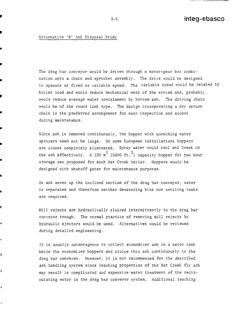
The drag bar conveyor would be dr iven through a motor-gear box combi-
na t ion on to a chain and sprocket assembly. The dr ive could be des igned
t o o p e r a t e a t f i x e d o r v a r i a b l e s p e e d . The v a r i a b l e s p e e d would b e r e l a t e d t o
bo i l e r l oad and would reduce mechanical wear of the system and, probably,
would reduce average water containment by bot tom ash. The d r i v i n g c h a i n
would b e o f t h e r o u n d l i n k t y p e . The des ign i nco rpora t ing a d r y r e t u r n
cha in i s the p re fe r r ed a r r angemen t f o r easy inspec t ion and access
during maintenance.
S ince ash i s removed continuously, the hopper w i t h quenching water
sp raye r s need no t be l a rge . On some European i n s t a l l a t ions hoppe r s
a re a lmos t comple t e ly e l imina ted . Sp ray wa te r would cool and break up
t h e a s h e f f e c t i v e l y . A 150 m (SO00 f t . 1 capac i ty hoppe r f o r two hour 3 3
s t o r a g e was proposed for each Hat Creek b o i l e r . Hoppers would be
des igned wi th shutof f ga tes for main tenance purposes .
As ash moves up t h e i n c l i n e d s e c t i o n o f t h e d r a g b a r c o n v e y o r , w a t e r
i s s e p a r a t e d a n d t h e r e f o r e n e i t h e r d e w a t e r i n g b i n s n o r s e t t l i n g t a n k s
a r e r e q u i r e d .
Mill r e j e c t s a re h y d r a u l i c a l l y s l u i c e d i n t e r m i t t e n t l y t o t h e d r a g b a r
conveyor trough. The normal prac t ice o f removing mill r e j e c t s by
h y d r a u l i c e j e c t o r s would be used. Alternatives would be reviewed
d u r i n g d e t a i l e d e n g i n e e r i n g .
I t i s u s u a l l y a d v a n t a g e o u s t o c o l l e c t e c o n o m i z e r a s h i n a water t ank
below the economizer hoppers and s luice this ash cont inuously to the
drag bar conveyor . However, it i s no t recommended f o r the desc r ibed
a sh hand l ing sys t em s ince l each ing p rope r t i e s o f t h e Hat Creek f l y ash
may r e s u l t i n compl ica ted and expens ive water t rea tment o f the rec i r -
cu la t ing wa te r i n t he d rag ba r conveyor sys t em. Add i t iona l l each ing

B-6 integ-ebasco
A l t e r n a t i v e ‘ B ’ Ash Disposal Study
t e s t s , a s d e s c r i b e d i n I n t e g - E b a s c o ’ s l e t t e r t o B . C . Hydro of 25 October ,
1978, c o u l d c l a r i f y t h e a b o v e t e c h n i c a l d e c i s i o n .
Ash i s coo led fu r the r i n t he d rag ba r conveyor t rough t o a temperature
s u i t a b l e f o r h a n d l i n g by be l t conveyor . The n o r m a l p r a c t i c e t o r e g u l a t e
t he wa te r t empea tu re i n t he t rough is t o c o n t r o l t h e makeup water supply
and l e t t h e e x c e s s w a t e r o v e r f l o w t o d r a i n . For a minimum discharge
sys t em, a s i n t he ca se o f Hat Creek, a coo l ing sys t em cons i s t ing o f hea t
exchangers and r e c i r c u l a t i n g pumps would b e r e q u i r e d . I n our c a l c u l a t i o n s
we assumed maximum wa te r t empera tu re i n t he t rough o f 62 C and a c losed
cycle cool ing water f low of approximately 40 l / s (650 USgpm).
0
A surge t ank would be incorporated to absorb the excess water during mi1:L
r e j e c t s r e m o v a l c y c l e s .
Ash from the d rag bar conveyor would be d i scharged on to a uni t c ross be l ; :
conveyor. From t h e u n i t cross b e l t c o n v e y o r a s h would be unloaded to e i - :he r
one of two aboveground co l l ec t ing conveyors ou t s ide t he bo i l e r p l an t . The re
wou ld be fou r un i t c ros s be l t conveyors (one pe r un i t ) and two bottom ash
c o l l e c t i n g c o n v e y o r s p e r p l a n t .
According t o McDowell-lvellman, quenching water sprays could break t h e
a s h e f f e c t i v e l y f o r d ry d i sposa l pu rposes and no ash crusher would be
requi red . Provis ion would be made f o r t h e i n s t a l l a t i o n o f a n a s h c r u s h e l -
a t t h e c h u t e b e t w e e n t h e i n c l i n e d s e c t i o n of the drag bar conveyor and the
u n i t cross b e l t c o n v e y o r i f it i s e s t a b l i s h e d t h a t s u c h a crusher could
reduce the compact ing e f for t a t t h e d r y a s h d i s p o s a l f i e l d . A modif ic-
a t i o n of the descr ibed bo t tom ash removal sys tem tha t could be cons idered a t
a l a t e r s t a g e o f e n g i n e e r i n g i s b r i e f l y d e s c r i b e d i n S e c t i o n 3.1.8.2.
3 . 1 . 2 P r e s s u r e F l y Ash Removal System (Drawing BCH 0064
si; 148)
I n t h i s s t u d y a p res su re sys t em fo r f l y a sh r emova l i s t e n t a t i v e l y s e l e c r e d
f o r t h e Dry Scheme - Al te rna t ive ‘B’ -due t o i t s a n t i c i p a t e d h i g h e r r e l i a b i l i t y
f o r p l a n t s l o c a t e d a t h i g h e l e v a t i o n s . However, d u r i n g t h e d e t a i l d e s i g n

B-7 integ-ekasco
Alternative 'B' Ash Disposal Study
phase, manufacturers should be allowed to bid alternative schemes. Some of the most common alternatives are briefly described in Section 5.1.9.
In a pressure system fly ash is discharged from collecting hoppers via an air lock valve and conveyed by an airstream inside a pressurized pipe. Pressure air is provided by a blower or compressor. This type of system can convey the dust over long distances. Dust leakage may be troublesome. Control requirements are more rigorous owing to sequential operation and the large pressure differential between flue gas in the hoppers and the conveying air.
For Hat Creek Plant there would be two 25.75 kg/s (100 TPH) pressure systsms per boiler unit based on worst coal, 85% as fly ash and maximum unit output (Turbine Valves Wide Open rating].
Fly ash would be removed intermittently from the collecting hoppers to the fly ash silo. Total cycle time per each 8 hour shift would be approximately 5 hours based on datum coal, 85% of total ash as fly ash at 100% unit out- put. (Worst coal at 85% total ash and maximum unit output would require 30 minutes longer.) This would provide approximately 3 hours margin when the removal cycle is idle to allow for abnormally low removal rate due to plugging, maintenance, etc. The system capacity would be reviewed in detailed engineering.
To provide the conveying air for each pressure system one 700 hp blolier would be required based on manufacturers' preliminary information. One spare blower would also be provided for each boiler unit.
Special provision, such as secondary hoppers, should be made for the removal of economizer ash to collect ash remote from the hot gas stream for the prevention of sintering. Large pieces of ash resulting from accumulations in the economizer tube banks are likely to occur. A debris box with sizing bars could be installed under the hoppers to prevent blockage in the system.

B-8 integ-ebasco
A l t e r n a t i v e ' B ' Ash Disposal Study
Space would b e p r o v i d e d f o r f u t u r e i n s t a l l a t i o n o f g r i n d e r s a t e a c h h o p p e r
t o b r e a k m a t e r i a l down to s izes which can be handled pneumat ica l ly if suc.h
g r i n d e r s are found necessary.
The cos t o f a pressure sys tem would v a r y s i g n i f i c a n t l y w i t h t h e number of
co l l ec t ing hoppe r s . In t h i s s tudy , based on i n t e r p o l a t i o n of v a r i o u s
manufac tu re r s ' da t a , 56 p rec ip i t a to r (or baghouse) hoppers, 8 economizer
hoppers and 8 a i r p rehea te r hoppe r s pe r bo i l e r a r e a s sumed . For Hat Creek
one a i r l o c k v a l v e would cost approximately $10,000. I t i s recommended
t h a t d u r i n g d e t a i l e d e n g i n e e r i n g a s tudy be per formed to op t imize the
number o f a sh hoppe r s i n r e l a t ion t o bo th a sh sys t em and p r e c i p i t a t o r
des igns .
3 .1 .3 Ash Transpor t a t ion Wi th in t he Power P l a n t Area
Bottom ash i s cont inuous ly removed and t r a n s p o r t e d t o t h e d i s p o s a l s i t e v i a
unit c r o s s b e l t , c o l l e c t i n g and t ranspor t conveyors and no s t o r a g e b i n s
would be r equ i r ed . Space p rov i s ion would be made f o r t h e i n s t a l l a t i o n of s to rage b ins and un load ing f ac i l i t i e s t o un load bo t tom a sh t o t rucks fo r
sale o r ' o t h e r u s e s . In normal opera t ion on ly one bo t tom ash co l lec t ing
conveyor would operate . In case of breakdown, s t a r t up a n d t r a n s f e r t o t:Ie other conveyor would be automatic.
The p a r t i c u l a r s o f e a c h u n i t c r o s s b e l t c o n v e y o r (4 ) will be as fo l lows:
Length 48 m (150 E t . ) Belt Width 0.610 m (24 i n . )
Belt Speed 1 .016 m/s (200 f t /min . )
Design Capacity 127 tonnes/hr (140 TPH)*
Drive Horsepower 8 hp.
The pa r t i cu la r s o f each bo t tom a sh co l l ec t ing conveyor ( 2 ) will be a s
fo l lows:
Length
Belt Width
Belt Speed
Design Capaci ty
Drive Horsepower
310 m (1200 f t . )
0.914 m (36 i n . )
1.524 m/s (300 f t /min.)
4 5 3 t o n n e s / h r (500 TPH)*
SO hp.

B-9 integ-ebasco
A l t e r n a t i v e ' B ' Ash Disposal Study
* Capac i t i e s a r e based on bottom ash a t 40% water content . Uni t
c r o s s b e l t c a p a c i t y i n c l u d e s 20% s u r g e c a p a c i t y and c o l l e c t i n g
be l t conveyors 10% surge capac i ty .
F o r t he p re s su re f l y a sh r emova l sys t em the re would be two s i l o s w i t h 1 2
hour s to rage capac i ty pe r two u n i t s . The volume of each s i l o i s 1400 m 3
(50,000 c u . f t . ) . One s i lo can be u sed a s s t andby fo r t he o the r . Less
s t o r a g e would be needed i f a continuous f ly ash removal system i s s e l e c t e d
a t t h e s t a g e of manufac tu re r s ' b id eva lua t ion . Each f l y a s h s i l o would be
equipped w i t h two c o n d i t i o n e r u n l o a d e r s t o f e e d f l y a s h t o t r a n s p o r t
conveyors o r d i r e c t l y t o t r u c k s . Each cond i t ione r un loade r would have
181 tonns /hr . (200 TPH) maximum c a p a c i t y ( d r y b a s i s ) and could add 10 - 30% wa te r by we igh t t o mo i s tu r i ze f l y a sh . S ince wa te r consumed by t h e
ash systems i s less than cool ing tower blowdown and o t h e r p l a n t w a s t e s ,
c o n s i d e r a t i o n would be given t o a h i g h e r w e t t i n g c a p a b i l i t y , p r e f e r a b l y
up t o 4 0 % . T e s t s will show whether such a water content i s f e a s i b l e f o r ash
t ranspor t by conveyors and compaction a t t h e d i s p o s a l a r e a . The c o n t r o l
o f t he un loade r s would be i n t e g r a t e d w i t h t h e c o n t r o l o f t h e t r a n s p o r t
c o n v e y o r s t o p r e v e n t t h e l a t t e r f rom ove r load ing . The d i scha rge chu te s
would be movable t o a l low emergency un loading in to t rucks . Another f lex ib le
chute f o r 9 ash d i scha rge would u n l o a d d r y f l y a s h t o t r u c k s i f , i n t h e
f u t u r e , d r y f l y ash i s t o be s o l d .
The r e l a t i v e l y small s t o r a g e c a p a c i t i e s o f t h e f l y a s h s i l o s a r e b a s e d on
con t inuous t r anspor t , sp read ing and compaction of ash to and a t t h e d i s p o s a l
s i t e and h i g h r e l i a b i l i t y o f the conveyor system.
3 .1 .4 Manpower Requirement
S t a f f i n g v a r i e s from one p l a n t t o a n o t h e r . The fo l lowing l abour r equ i r e -
ments i s assumed:

I
I
I
1
1
1
1
1
I
I
B-10 integ-ebasco
A l t e r n a t i v e 'B' Ash Disposal Study
P e r S h i f t
Foreman and Control Panel - 1
Opera to r In s ide Power House - 1
O p e r a t o r f o r P r e c i p i t a t o r Zone and Fly Ash System - 1
Operator for Conveyors - 1
Total Operat ion Maintenance
Ash Handling Equipment a t Power 20 3 ( 2 mechanics and
Plant Area ( 5 crews f o r 3 s h i f t 1 e l e c t r i c i a n
o p e r a t i o n )
Transport Conveyors and Mobile
Equipment a t D i s p o s a l S i t e (See Section 5 . 2 . 3 )

B-11 integ-ebasco
A l t e r n a t i v e ' B ' Ash Disposal Study
3 . 1 . 5 Ash Flow Rates (At Power P lan t 100% Capaci ty Fac tor )
Coal Designation Datum Worst
H W MJ/Kg (Btu/ lb) 12.79 (5500) Ash Content 29%
12.21 (5250) 30%
PER W I T PER 4 UNITS (560 MW)
PER U S I T (560 MW)
PER 4 W I T S (VIVO) * (WVO) 'ii
Coal Consumption Kg/sec (?PHI
Total i s h P r o d u c t i o n Kdsec
Bottom Ash 45% o f T o t a l Ash
125.4 (498)
(145) 36 .4
1048.3 3145.0
16.4 (65)
1415.0 471.7
(36) 9 . 1
786.2
520.0 (1992)
145.5
12579.8 4193.3
(578)
(260) 65.5
1887.0 5660.9
3145. o
18 .7
1617.4 539 .1
(74)(1)
10 .4
898.6 (41 )
555.0 (2203)
167.0(:?)
4792.3 14376.9
(660)
(297) 78.9
2156.5 6469.6
Fly Ash 8 5 % of To ta l Ash
7 5 % o f T o t a l Ash Kg/sec 27.3 P H I MgIDay 2358.7 9434.9 2695.7 10752.7
109.2 (108)
31.2 (433) C 4 ) (124) (495)
124.8
* Turbine va lves wide open ra t ing .
B-12 integ-ebasco
A l t e r n a t i v e ' B ' Ash Disposal Study
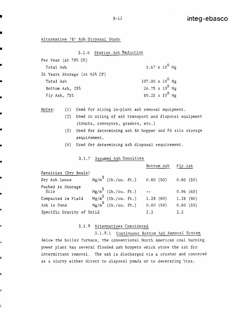
3.1.6 Stat ion Ash-Reduct ion - . -
Per Year ( a t 78% CF)
T o t a l Ash 3 .67 x 10 blg 6
35 Years S torage (a t 65% CF)
T o t a l Ash 107.00 x 10 Mg
Bottom Ash, 25% 26.75 x 10 blg
Fly Ash, 7 5 % 80 .25 x 10 Mg
6
6
6
- Notes: (1) Used for s iz ing in -p lan t ash removal equipment .
(2) Used i n s i z i n g o f a s h t r a n s p o r t a n d d i s p o s a l e q u i p m e n t
( t r u c k s , c o n v e y o r s , g r a d e r s , e t c . )
(3) Used fo r de t e rmin ing a sh BA hopper and FA s i l o s t o r a g e
requirement .
(4) Used fo r de t e rmin ing a sh d i sposa l r equ i r emen t .
3.1.7 Assumed Ash D e n s i t i e s
Bottom Ash Fly Ash
D e n s i t i e s (Dry Basis)
Dry Ash Loose Mg/m3 ( l b . / c u . f t . ) 0.80 (50) 0.80 (50)
Packed i n S t o r a g e S i l o Mg/m ( l b . / c u . f t . ) -- 3
3 3
0.96 (60)
Compacted i n F i e l d Mgjm ( l b . / c u . f t . ) 1 . 2 8 (80) 1.28 (80)
Ash i n Pond Mg/m ( l b . / c u . f t . ) 0 . 8 0 (50) 0.80 (50)
S p e c i f i c G r a v i t y of S o l i d 2 . 3 2 . 3
3 .1 .8 Al t e rna t ives Cons ide red
3.1.8.1 Cont inuous Bottom .Ash Removal System
Below the bo i le r furnace , the convent iona l Nor th Amer ican coa l burn ing
power p lan t has severa l f looded ash hoppers which s tore the ash for
i n t e r m i t t e n t r e m o v a l . The ash i s d i scha rged v i a a c r u s h e r and conveyed
as a s l u r r y e i t h e r d i r e c t t o d i s p o s a l p o n d s o r t o d e w a t e r i n g b i n s .

B-13
~~
integ-ebasco
Alternative 'B' Ash Disposal Study
an established method of proven reliability for handling bottom ash in Continental Europe is continuous removal by drag bar conveyor. This method is now being introduced into North America and facilities are available to manufacture the equipment under licence from proven European suppliers. Alberta Power Ltd. plans to put their 375 MlV No. 5 Unit at Battle River Generating Station into service in 1981 with a drag bar conveyor for bottom ash removal. This would be the first North American utility plant with such a system.
OPERATING EXPERIENCE DRAG BAR CONVEYOR
Some of the power plants that have successfully operating drag bar con- veyors for bottom ash removal from boiler furances are listed below:
Utility Station Unit Size i4VJ
Lausivannikon Vorma A.G. (Finland) Thakoluoto 1 x 220
The Helsinki Electricity Works (Finland) Hanasaari 2 x 120.c Rheinisch Wesfalisches Elektrizitatswerk Niederaussen 2 x 150
(West Germany) 4 x 300 2 x 600
-
, I
Steinkohlen Elektrizitat Aktiengesellschaft Gemeinschafts- (West Germany) Kraftwerk-West
The technical evaluation and cost estimate of the drag bar conveyor have been discussed in the report "Evaluation of a Continuous Bottom Ash Removal System Incorporating a Drag Bar Conveyor for Hat Creek Power Plant" by Integ-Ebasco in May 1978. The main advantages and disadvantages of the drag bar conveyor system are summarized below:
Advantages - Continuous removal of bottom ash from the furnace especially attractive for high ash content coal.
- Low capital, operation and maintenance costs.
*Note - Boilers sized for 270 M'! thermal output to cover industrial steam demand. -

B-14 integ-ebasco
A l t e r n a t i v e 'B' Ash Disposal Study
- Simple cont ro l requi rements
- Low energy consumption
- No need for l a rge s torage hoppers under bo i le r and hence reduced boiler
he igh t
- Simple water treatment
Disadvantages
- No redundant o r s t a n d b y f a c i l i t i e s
- Increased water evapora t ion i n t o furnace
I t i s b e l i e v e d t h a t f o r t h e h i g h a s h c o n t e n t i n Hat Creek coal the advan-
tages of the drag bar conveyor overweigh the above disadvantages and
such a system i s the p re fe r r ed one .
3 .1 .8 .2 Modif ica t ions o f the Cont inuous Bottom A z h Removal System
In the preferred bot tom ash removal system, bot tom ash f rom the drag bar
conveyors i s unloaded on to un i t c ross be l t conveyors and t h e n t r a n s f e r r e d
to aboveground co l l ec t ing conveyors l oca t ed ou t s ide t he bo i l e r p l an t a s
d e s c r i b e d i n S e c t i o n 3 . 1 . 1 . M o d i f i c a t i o n s o f t h i s &em would be unloading
of bot tom ash from the d rag ba r conveyors d i r ec t ly on to unde rg round o r above-
ground co l lec t ing conveyors wi thout in te rmedia te c ross b e l t conveyors.
Underground c o l l e c t i n g c o n v e y o r s a r e more c o s t l y and maintenance could
be l e s s conven ien t . However, t h i s is widely used in Nest Germany and
dese rves more d e t a i l e d c o n s i d e r a t i o n a t a l a t e r s t a g e o f e n g i n e e r i n g .
Based on a pre l iminary eva lua t ion per formed in Apr i l 1978 t h e i n c r e a s e d
inves tment cos t f o r the underground conveyors i s approximately $715,000
o r 6% of the t o t a l BA removal and c o l l e c t i n g s y s t e m c o s t .
I n s t a l l a t i o n o f t h e d r a g bar conveyors in the IV-E d i r e c t i o n (same as t h e
u n i t c e n t e r l i n e s ) and aboveground c o l l e c t i n g c o n v e y o r s i n s i d e t h e p l a n t

m
I
.
B-15
A l t e r n a t i v e ' B ' Ash Disposal Study
~-
integ-ebasco
t o r e c e i v e b o t t o m a s h d i r e c t l y from the d rag bar conveyors could a l so be
c o n s i d e r e d d u r i n g t h e d e t a i l e d e n g i n e e r i n g a f t e r b o i l e r m a n u f a c t u r e r and
des ign a r e s e l ec t ed s ince r ea r r angemen t o f t he bo i l e r p l an t may be requi red .
3 .1 .9 A l t e rna t ive F ly Ash Removal System
.As d i scussed i n Sec t ion 3 . 1 . 2 , t h e r e c o u l d b e s e v e r a l d i f f e r e n t f l y ash
removal sys tems capable o f per forming sa t i s fac tor i ly for Hat Creek Power
P l a n t .
3.1.9.1 Vacuum System
The f l y ash i s i n t e r m i t t e n t l y removed from t h e c o l l e c t i n g h o p p e r s i n a
s e q u e n t i a l o p e r a t i o n and sepa ra t ed from t h e a i r s t r e a m i n a cyclone before
d i s c h a r g i n g i n t o a s t o r a g e s i l o . The vacuum can be produced by a hydraulic
e j e c t o r o r by a mechanical pump
In wet ash s lu ic ing schemes the vacuum system would operate i n conjunct ion
w i t h s l u r r y t r a n s p o r t a t i o n . H y d r a u l i c w e t t e r s would be i n s t a l l e d r e m o t e
from t h e p r e c i p i t a t o r c o l l e c t i n g h o p p e r s . Ash i s removed d r y and s l u r r y
i s formed a t t h e h y d r a u l i c w e t t e r s .
A complete vacuum system i s e f f e c t i v e . Dust leakage i s minimized w i t h t h i s system. The cost of t h e vacuum system is u s u a l l y lower than o f a
pressure sys tem. However, i t may be o f l i m i t e d u s e on p l a n t where long
conveying dis tance o r h i g h a l t i t u d e are encountered.
3.1.9.2 Vacuum-Pressure System
A combined vacuum-pressure system can incorporate the merits o f bo th sys-:erns,
i . e . a vacuum sys t em to co l l ec t t he dus t f rom numerous p r e c i p i t a t o r h o p p e r s
t o a loca l bu f fe r hoppe r o r t r a n s f e r t a n k and a pressure sys tem to d i scharge
from the bu f fe r hoppe r t o a r e m o t e s i l o .
8-16 integ-ebasco
A l t e r n a t i v e 'B' Ash Disposal Study
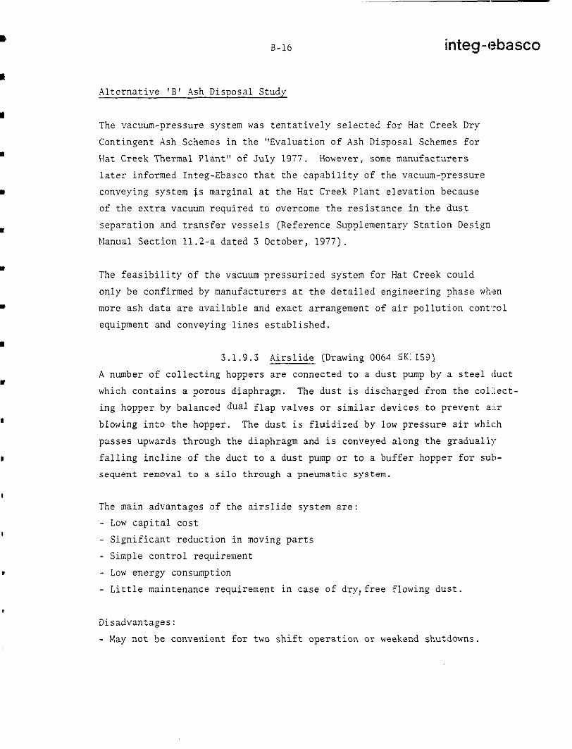
The vacuum-pressure system was t e n t a t i v e l y s e l e c t e d f o r Hat Creek Dry
Contingent Ash Schemes in t he "Eva lua t ion o f Ash Disposal Schemes f o r
Hat Creek Thermal Plant" of July 1977. However, some manufac turers
l a t e r i n fo rmed In t eg -Ebasco t ha t t he capab i l i t y o f the vacuum-pressure
conveying system i s m a r g i n a l a t t h e Hat Creek Plant elevation because
o f t h e e x t r a vacuum requ i r ed t o ove rcome t he r e s i s t ance i n t h e d u s t
s e p a r a t i o n and t ransfer vessels (Reference Supplementary Stat ion Design
Nanual Section 11.2-a dated 3 October , 1977) .
The f e a s i b i l i t y of t h e vacuum pres su r i zed sys t em f o r Hat Creek could
only be confirmed by manufacturers a t t h e d e t a i l e d e n g i n e e r i n g p h a s e wh(?n
more a s h d a t a a r e a v a i l a b l e and exac t a r rangement o f a i r po l lu t ion cont - ro l
equipment and conveying l ines es tabl ished.
3 .1 .9 .3 A i r s l i d e (Drawing 0064 SK: 1591 A number o f c o l l e c t i n g h o p p e r s a r e c o n n e c t e d t o a dus t pump by a s t e e l d u c t
which contains a porous diaphragm. The dust i s discharged from the co1:lect-
ing hopper by balanced dual f lap valves o r s i m i l a r d e v i c e s t o p r e v e n t a:!r
b lowing in to the hopper . The dus t i s f l u i d i z e d by low p r e s s u r e a i r which
passes upwards through the diaphragm and i s conveyed a long the gradual ly
f a l l i n g i n c l i n e o f t h e d u c t t o a d u s t pump o r t o a buf fer hopper f o r sub-
sequent removal t o a s i l o t h r o u g h a pneumatic system.
The main advantages o f t h e a i r s l i d e s y s t e m a r e :
- Low c a p i t a l c o s t
- S i g n i f i c a n t r e d u c t i o n i n moving p a r t s
- Simple control requirement
- Low energy consumption
- Li t t l e ma in tenance r equ i r emen t i n ca se o f d ry : f r ee f l owing dus t .
Disadvantages:
- May not be convenient fo r two s h i f t o p e r a t i o n OT weekend shutdowns.
B-17 integ?ebasco
A l t e r n a t i v e 'E' Ash Disposal Study
3 . 1 . 9 . 4 Air Je t System (Drawing 0064 SK 140)
Ash f a l l s t h r o u g h t h e f l y a s h h o p p e r s i n t o i n d i v i d u a l r o t a r y f e e d e r s .
Each f e e d e r d e l i v e r s a c o n t r o l l e d amount o f a s h t o i t s a s s o c i a t e d a i r j e t b l o w e r . R e ash i s d e l i v e r e d i n a constant f low f rom the j e t
b l o w e r s t o a buf fer hopper which se rves as a l a r g e c o l l e c t i o n p o i n t .
Ash f rom the buffer hopper i s conveyed t o t h e f l y a s h s i l o t h r o u g h a
pneumatic system.
The a i r j e t system consumes more energy than the a i rs l ide, but it i s
more s u i t a b l e f o r p l a n t s whose f l y a s h i s d i f f i c u l t t o f l u i d i z e .
3 .1 .9 .5 General Notes on t h e A i r s l i d e and Air Jet Systems
With t h e h i g h ash con ten t and low h e a t v a l u e o f Hat C r e e k c o a l , t h e c o n t -
i nuous f l y a sh r emova l sys t ems ( a i r s l i de and air j e t systems) may have
a d v a n t a g e s , p a r t i c u l a r l y when the d rag ba r conveyor has been s e l ec t ed
a s t h e p r e f e r r e d system for cont inuous bo t tom ash removal . If a sh i s being removed continuously the equipment has smaller c a p a c i t y , i s opera ted
w i t h o u t t h e r i g o r s o f f r e q u e n t s t a r t i n g and s t o p p i n g a n d i n s t a l l e d kN r a t i n g s o f m o t o r d r i v e s a r e much lower . However , t he a i r s l i de and a i r e j e c t o r s y s t e m s c o u l d b e c o n s i d e r e d a s a l t e r n a t i v e s i f l a t e r i n v e s t i g -
a t i o n show t h a t t h e y are s u i t a b l e f o r Hat Creek coa l . According to BR?
Burn Test Report by B . N . , Hat Creek f ly a sh " acqu i red a g r e a s y t e x t u r e "
a n d " s l i d i n a v i scous mass down t h e h o p p e r s l i d e s " . I t was sugges t ed t ha t
t h i s e f f e c t a r o s e due t o b o i l e r o p e r a t i o n p a r t i a l l y on o i l f u e l between
t e s t r u n s . If t h e Hat Creek bo i le rs opera te on a two s h i f t b a s i s , it i s
p o s s i b l e t h e same phenomenon may be experienced. In t h i s c a s e t h e
m a n u f a c t u r e r s o f a i r s l i d e o f a i r e j e c t o r s y s t e m s s h o u l d b e i n v i t e d t o b i d
on the i r sys t em du r ing t he fo rma l enqu i ry s t age , i f they recommend it a s
t h e b e s t s y s t e m f o r Hat Creek. Proper eva lua t ion of such a p roposa l ,
however , should p robably inc lude pr ior inspec t ion of such opera t ing fac i l i
t i e s i n t h e U.S.A. , t h e U . K . o r Cont inenta l Europe .


- -- -7
L
4
I -
/' / /'
*
4
..
i-
i
1 I

I -"
C ! i O " I I
I L- i

,
.. .
I
:
~~ .
7
y ':
. >
. ~~. . .
2. \ \ " r
.r
"

4 '
i BUFFEFL A.5H HOPPERS
. J
I "~

i \ J
/
I
i I

B-18
A l t e r n a t i v e ' B ' Ash Disposal Study
3.2 Ash Transpor ta t ion , Dis t r ibu t ion , Compact ion and Disposa l Area Reclamation
3.2.1 System Description
3 . 2 . 1 . 1 Ash Transpor ta t ion ( see Drawings BCH 0064 SK 147, 148 and 151)
F ly ash and bo t tom ash , d i scharged f rom the power p l a n t , will be moved
t o a f i x e d p o i n t a t t h e n o r t h s i d e o f t h e d i s p o s a l a r e a i n Mid Medicine
Creek by two be l t conveyors (Nos. 101.4 and 1018) . In previous s tudies
a comparison was presented showing the economic advantages of using
b e l t c o n v e y o r s r a t h e r t h a n t r u c k s f o r a s h t r a n s p o r t a t i o n ; so for t h e
purpose of t h i s s t u d y o n l y b e l t c o n v e y o r s will be cons idered . However,
the above conclus ion has to be checked a t the s tage o f manufac turers '
b i d e v a l u a t i o n when more p r e c i s e c o s t d a t a become a v a i l a b l e . The con-
v e y o r s a n d t h e t r a n s f e r p o i n t s will be a r ranged in such a manner t h a t
bottom ash will normal ly be depos i ted on t h e b e l t s on t o p o f f l y a s h ,
thereby reducing the risk o f d u s t i n g .
The conveyor rou te has been se lec ted so t h a t a s i n g l e d i r e c t f l i g h t t o
the edge of Mid Medicine Creek i s p o s s i b l e . T h i s will r e s u l t i n t h e
s h o r t e r c o n v e y o r b e l t s , t h e least number o f t r ans fe r po in t s and consequen-
t i a l l o w e r c a p i t a l c a s t . The a b s e n c e o f t r a n s f e r p o i n t s o n t h e l o n g
f l i g h t will a l s o r e d u c e t h e p o s s i b i l i t y o f f l y a s h a n d b o t t o m a s h becoming mixed on t h e bel ts before reaching the v a l l e y . With a f a i r l y
h igh mois ture conten t in f ly ash and bo t tom ash , a small amount
of ash is e x p e c t e d t o s t i c k t o t h e b e l t , p a r t i c u l a r l y d u r i n g w i n t e r
o p e r a t i n g c o n d i t i o n s . To prevent a bu i ldup of ash on t h e r e t u r n i d l e r s
i t i s s u g g e s t e d t h e b e l t b e t u r n e d o v e r f o r t h e r e t u r n r u n so t h a t o n l y
t h e c l e a n s i d e of t h e b e l t i s i n c o n t a c t w i t h t h e i d l e r s . O p e r a t i n g
conveyors under winter condi t ions i s n o t e x p e c t e d t o p r e s e n t a problem.
The conveyors would be unheated but have a hood a l lowing easy access f o r
s e r v i c e a n d p r o t e c t i o n a g a i i i s t d i r e c t p r e c i p i t a t i o n a n d d u s t i n q . 4 larice
number o f m i n e s i n t h e Yukon, B r i t i s h Columbia and across Canada succes:;fully
use unheated and unprotected conveyors f o r t he i r p roduc t ion sys t ems . Each conveyor w i l l b e c a p a b l e o f c a r r y i n g t h e f u l l a s h p r o d u c t i o n
volume, so t h e a s h t r a n s p o r t a t i o n s y s t e m c a n c o n t i n u e t o f u n c t i o n i n
t h e e v e n t t h a t e i t h e r o f t h e two conveyors i s unavai lab le due t o r e p a i r
o r maintenance. For the purpose of b u i l d i n g t h e d r a i n a g e c o u r s e s , b o t t i ~ m

B-19 integ-ebasco
A l t e r n a t i v e ' B ' Ash Disposa l S tudy
a s h and f l y a s h would be loaded on to separa te conveyors to the working
area o f Xedic ine Creek Val ley . A roadway along the conveyors w i l l
p rovide easy access for the opera t ion and main tenance of the conveyors ,
The ash t ranspor ta t ion conveyors (Nos. lOlA and 1015) a re downh i l l con-.
veyors and when running loaded, they will feed power back t o t h e p l a n t . ,
To ensure the sa fe s topping of the sys tem, mechanica l d i sk b rakes will
a l so be p rov ided . This arrangement is becoming i n c r e a s i n g l y common
wherever long conveyors are used for moving l a r g e volumes of m a t e r i a l
downhil l .
The p a r t i c u l a r s of each conveyor (101A and lO1B) w i l l be as fo l lows:
Length
Belt Width
Bel t Speed
Design Capaci ty
Tai l End E l e v a t i o n
Head End E l e v a t i o n
Drive Horsepower
2950 m (9678 f t . )
0.914 m (36 i n . )
2.24 m l s (440 f t . /min.)
851 tonnes/hour (938 TPH)
1415 Q (4642 f t . )
1260 m (4133 f t . ) R 1
2 x 150 kW (2 x 200 hp)
3.2.1.2 Ash D i s t r i b u t i o n and compaction (see Drawings
BCH 0064 SK 147, 150, 151, and 162 t o 167
A f e a s i b l e method of ash d i s t r ibu t ion and depos i t ion is g e n e r a l l y
desc r ibed . Spec i f i c s o f t he ac tua l p rocedure t o b e adopted will be
d e v e l o p e d i n t h e d e t a i l e d e n g i n e e r i n g p h a s e on t h e b a s i s o f f u r t h e r
s t u d i e s a n d , p o s s i b l y , a v a l l e y model. The adopted procedure shall have
some f l e x i b i l i t y f o r o n - s i t e a d j u s t m e n t s r e q u i r e d t o i m p r o v e t h e s y s t e m
a s o p e r a t i o n a l e x p e r i e n c e is gained.
Rev. 1

B-20 integ-ebasco
A l t e r n a t i v e ' B ' Ash Disposa l S tudy
When t h e d i s p o s a l s i t e i n Mid Medicine Creek has been prepared by removing
a l l v e g e t a t i o n a n d t o p s o i l , f l y ash and bottom ash w i l l move from the
power p l a n t t o t h e d i s p o s a l a r e a v ia two f ixed conveyors (Nos. l O l A and
101B), two movable conveyors with t r i p p e r s (Nos. 102A and 102B), two
mobile conveyors (Nos. 103A and 103B), and two mobi le s tacker conveyors
(Nos. 104A and 104B). The f i n a l p l a c i n g and compaction of the ash will
b e c a r r i e d o u t by a pa i r of l a r g e r u b b e r t i r e d d o z e r s . Drawing SK 150
shows a typ ica l a r r angemen t of t h e a s h d i s t r i b u t i o n e q u i p m e n t a t t h e
head end of conveyors 102A and 102B. The combined mobile conveyor (No.
103) and the mobile s tacker conveyor (No. 104) o p e r a t i o n a l r a d i u s i s
about 65 m. The ash p i le p roduced by these systems of conveyors will be
dozed outwards and down t h e s l o p e t o a f u r t h e r r a d i u s o f a b o u t 85 m.
Thus ash can be convenient ly deposi ted over a d i s t a n c e of 150 rn f rom the
head end o r t r i p p e r of a movable conveyor (No. 102A o r 102B).
A t the head end of t r anspor t a t ion conveyors l O l A and l O l B a f i x e d
t r a n s f e r p o i n t w i l l p e r m i t c o m p l e t e f l e x i b i l i t y i n r o u t i n g so t h a t a s h
f rom e i ther conveyor l O l A o r 1U1B could be d i scha rged t o e i t he r conveyor
102A o r 102B. Conveyors 102A and 10ZB w i l l o p e r a t e a l o n g r a d i a l l ines
emanat ing f rom the t ransfer point and will t h u s p i v o t a r o u n d t h i s p o i n t
as t hey swing ove r t he yea r s , d i s t r ibu t ing ash sideways through the
v a l l e y , c o v e r i n g a n arc of about 170'.
Conveyors 102A and 102B w i l l h a v e a n i n i t i a l l e n g t h (maximum) of about
1200 m, and w i l l c o n s i s t of s k i d mounted head and t a i l t e r m i n a l u n i t s
s epa ra t ed by a number of sk id mounted conveyor support tables supported
on prepared benches s loping down t h e n o r t h e r n f a c e o f t h e Mid Medicine
Creek Val ley. The conveyors can be shortened or lengthened, as r equ i r ed ,
and can be moved sideways on t h e i r s k i d s t o new l o c a t i o n s by means of
t he sp read ing doze r s .
Rev,. 1

5-2 1
A l t e r n a t i v e ' B ' Ash Disposa l S tudy
A sequence of ash depos i t ion wi th the movements of conveyors 102A and
102B from t h e i r i n i t i a l l o c a t i o n t o t h e i r uppermost reach ( shor tes t
l e n g t h ) a l o n g t h e f i r s t p r e p a r e d b e n c h i s i l l u s t r a t e d on ske tches 162
and 163 as fo l lows:
STAGE 1:
The i n i t i a l f l o w of a sh w i l l be v i a conveyor 102A which w i l l terminate
a t , o r n e a r , e l e v a t i o n 1195 about 150 m west of t h e t o e of t h e dam. The
mobile conveyor 103A w i l l p r o b a b l y n o t b e n e e d e d f o r t h e f i r s t few
weeks. Ash w i l l f l ow d i r ec t ly f rom conveyor 102A t o t h e m o b i l e s t a c k e r
conveyor 104A a t which it will be s tockpi led. The dozer w i l l spread i t
o u t and compact i t . The d i r e c t i o n o f movement of the mobile conveyor
and t h e s t a c k e r i s shorn by arrows.
STAGE 2 :
The conveyor 102B w i l l fo l low a prepared bench a t a h i g h e r level and
w i l l t e rmina te a t o r near e levat ion 1215. The mobile conveyor 103B and
t h e s t a c k e r 104B w i l l b e o p e r a t i n g on a s lope no t exceeding 5 p e r c e n t .
By ma in ta in ing a h e i g h t d i f f e r e n t i a l of about 20 m between the s t a c k e r s
104A and 104B. a s u i t a b l e s l o p e ( a b o u t 20 pe rcen t ) can b e a t t a i n e d f o r
t h e d o z e r s o p e r a t i n g o v e r 85 m reach. The top sur face o f ash p rev ious ly
depos i t ed by the conveyor 102A i s o u t l i n e d i n d o t t e d l i n e s .
STAGE 3:
The conveyor 102A w i l l b e f i l l i n g up only a p o r t i o n of t h e v a l l e y w i d t h
a t e l e v a t i o n 1195 because o f l imi ta t ion on conveyor systen reach. The
remain ing por t ion of t h e v a l l e y w i d t h will b e f i l l e d on t h e n e x t s h i f t
of the conveyor bench along a d i f f e r e n t r a d i a l l i n e . The r e t r a c t i n g
conveyor 102B will be bu i ld ing up a sh to e l e v a t i o n 1215 o v e r t h e e l e v a t i o n
1195 s u r f a c e b u i l t up by the conveyor 102A.
Rev. 1

B-21a integ-ebasco
A l t e r n a t i v e 'B' Ash Disposa l S tudy
STAGE 4 :
This is an ex tens ion of S tage 3 i n t h e c o n t i n u a t i o n of upward travel of
both movable conveyors.
STAGE 5 :
This w i l l b e t h e u p p e r n o s t e x t e n t o f r e t r a c t i o n f o r b o t h c o n v e y o r s on
t h e b e n c h e s s t a r t e d i n S t a g e 1.
STAGE 6 :
The conveyor 102 B w i l l b e f i l l i n g up t o t h e n e x t l e v e l , e l e v a t i o n 1 2 3 0 ,
as i t extends downward on the previous bench.
The conveyor 102A w i l l s tar t on i t s downward ex tens ion a long a d i f f e r e n t
r a d i a l l i n e on a new bench (p ro jec t ion shown i n d o t t e d l i n e s ) . T h i s
bench w i l l s l o p e downward to e leva t ion 1230 , run ho r i zon ta l ly t he reon t c ,
t he edge of t h e p l a t e a u and then s lope down a g a i n t o elevation 1195 t o
f i l l a n o t h e r p a r t o f the wid th of t h e v a l l e y .
Four i somet r ic d rawings (SK164 t o 1 6 7 ) show t h e o v e r a l l view of the Mid
Medic ine Creek Val ley be tween the t ransfer po in t (head end of f ixed
conveyors l O l A and 101B) and t h e make-up water r e s e r v o i r dam a t d i f f e r e n t
times dur ing t he d i sposa l ope ra t ions a s fo l lows ( r e fe rences t o time
p e r i o d s are a p p r o x i m a t e , a n d f o r i l l u s t r a t i o n o n l y ) .
SK164:
Approximately 6 months f rom the s tar t of ash disposal , the movable
conveyor 102A w i l l b e f i l l i n g up t o e l e v a t i o n 1195. The movable conveyor
Rev. 1

I
B-21b integ-ebasco
A l t e r n a t i v e 'B' Ash Disposa l S tudy
102B w i l l be fo l lowing a long on the nex t l eve l , e l eva t ion 1215 . On ly a
p a r t o f t h e t o t a l w i d t h o f t h e v a l l e y i s f i l l e d up t o e l e v a t i o n 1195 a t
t h i s s t a g e .
SK165:
This s k e t c h shows an extens ion of the d i s p o s a l a r e a a c t i v i t y shown on
the p rev ious ske tch approximate ly 1 year f rom s ta r t . The e n t i r e w i d t h
o f t h e v a l l e y is f i l l e d t o e l e v a t i o n 1195 along a s t r i p a d j a c e n t t o the
dam. Further downstream, the val ley i s o n l y p a r t i a l l y f i l l e d .
SK166:
Approximately 3 t o 4 years f rom s tar t , t h e v a l l e y w i l l b e f i l l e d up t o
the top (approximate e leva t ion 1243) a long the dam. The movable conveyor
102A will b e f i l l i n g up t o e l e v a t i o n 1230 followed by the movable conveyor
102B a t e l e v a t i o n 1 2 4 3 .
SK167:
T h i s sketch shows ex tens i o n of t h e ac t iv i t ies on t h e p rev ious ske tch .
A d j a c e n t t o t h e dam, t o p s o i l w i l l be spread and seeded € O K p r o t e c t i v e
vege ta t ion cover .
The lowest 20 m l a y e r i n t h e v a l l e y w i l l b e f i l l e d by the conveyor 102A
and the topmost 12 m l a y e r by the conveyor 102B. The two in t e rmed ia t e
l a y e r s of 20 m and 15 m th i ckness will b e b u i l t up by e i t h e r of t h e
conveyors . Su f f i c i en t p l a t eau w i l l be provided by the movable conveyor
102A on which the fol lowing conveyor 102B can work.

rl
B-21c
~
integ-ebasco
1
-
I .
A l t e r n a t i v e ' B ' Ash Di suosa l S tudy
Drawing SK 151 shows t h e p l a n of t he a sh d i sposa l sys t en . Drawing SK
152 shows a l o n g i t u d i n a l s e c t i o n o f t h e v a l l e y w i t h t h e p r o f i l e s of
compacted (warm months) and not ful ly compacted (severe winter months)
a s h l a y e r s f o r t h e f i r s t 6 y e a r s of a sh d i sposa l . Th icknesses of t hese
s l i c e s w i l l depend l a r g e l y o n t h e q u a n t i t i e s of ash produced during
t h e s e two g e n e r a l l y c l a s s i f i e d p e r i o d s (warm months and severe winter
months) i n the yea r .
The a s h w i l l b e d e p o s i t e d i n l a y e r s of about 0.3 m ( 1 . 0 f t . ) t h i c k n e s s
and the compact ion w i l l b e e f f e c t e d by the rubber t i red dozers , used for
s p r e a d i n g t h e material. Lined dra inage courses will be p rov ided i n t he
a s h p i l e as shown i n S e c t i o n B of Drawing SK 15.2. This w i l l r e q u i r e
proper sequencing of f l y a s h f b o t t o m a s h d e p o s i t i o n on t h e 12 t o 20 m
h i g h l a y e r s b u i l t by movable conveyors.
When bot tom ash only is requ i r ed as d r a i n a g e l a y e r s i n c e r t a i n a r e a s ,
bottom ash will be loaded a t t h e power p lan t on to one o f the ash t rans-
p o r t a t i o n c o n v e y o r s , e i t h e r l O l A o r lOlB and rou ted v i a conveyors 102A
o r 102B, as r e q u i r e d , t o t h e a p p r o p r i a t e area f o r d i s p o s a l .
An arrangement of conveyors and dozers for placing, spreading and compact- ing material has been u sed i n t he cons t ruc t ion of s e v e r a l l a r g e dam
p r o j e c t s i n c l u d i n g t h e P e a c e River Dam i n B.C. By provid ing two f u l l
capaci ty , independent conveying systems it w i l l b e p o s s i b l e t o c o n t i n u e
t h e a s h d i s t r i b u t i o n .and d i sposa l ope ra t ion a t f u l l p l a n t o u t p u t while
one set of conveyors i s being moved t o a new p o s i t i o n o r is out of
s e r v i c e d u e t o breakdown o r maintenance.
A s the conveyors swing westward through the valley the conveyors w i l l
r each a pos i t i on abou t no rma l t o t h e a c t u a l c o n t o u r l i n e s o f t h e t e r r a i n
R e v . 1

1
I
integ-ebasco
8-2 1 d
A l t e r n a t i v e '8 ' Ash Disposal Study
r e s u l t i n g i n a s t e e p e r downwards ang le of the conveyors . However, as
t h e head end of the lower conveyor, conveyor 102A. w i l l always be some
20 m above the va l ley bo t tom, the downward angle w i l l no t exceed s ix
deg rees , t he maximum ang le f o r movable conveyor operation.
The p a r t i c u l a r s of t h e a s h d i s t r i b u t i o n and compaction equipment are a s
fo l lows :
Conveyors 102A and 102B (Movable, wi th t r i p p e r s )
m
R1 Length 1200 m (3937 f t . )
Belt Width Maximum 0.914 m (36 in.)
Belt Speed 2.24 mls (440 ft./min.)
Design Capacity (each) 851 Tonnes/hour (938 TPH)
Ta i l End E leva t ion 1255 m (4117 f t . )
Head End e l e v a t i o n Varies down t o 1195 m (3920 f t . )
Drive Horsepower (each) Varies t o 225 klJ (300 hp) R 1
Conveyors 103A and 103B (Mobile, Mounted on C a t e r p i l l a r T r a c k s )
Length 30 m (100 f t . )
Belt Width 0.914 m (36 in.)
B e l t Speed 2.24 mls (440 f t . /min.)
Design Capaci ty (each) 851 tonneslhour (938 TPH) Drive Horsepower (each) 15 kW (20 hp)
Conveyors 104A and 104B (Mobile Stackers, Mounted on C a t e r p i l l a r
Tracks)
Length
Belt Width
Belt Speed
Design Capacity (each)
Drive Horsepower (each)
36 m (120 f t . )
0.914 m (36 in.)
2.24 mls (440 f t . /min.)
851 tonneslhour (938 T W )
37 kW (50 hp)
Rev. 1
B-21e
A l t e r n a t i v e ' B ' Ash Disposal Study
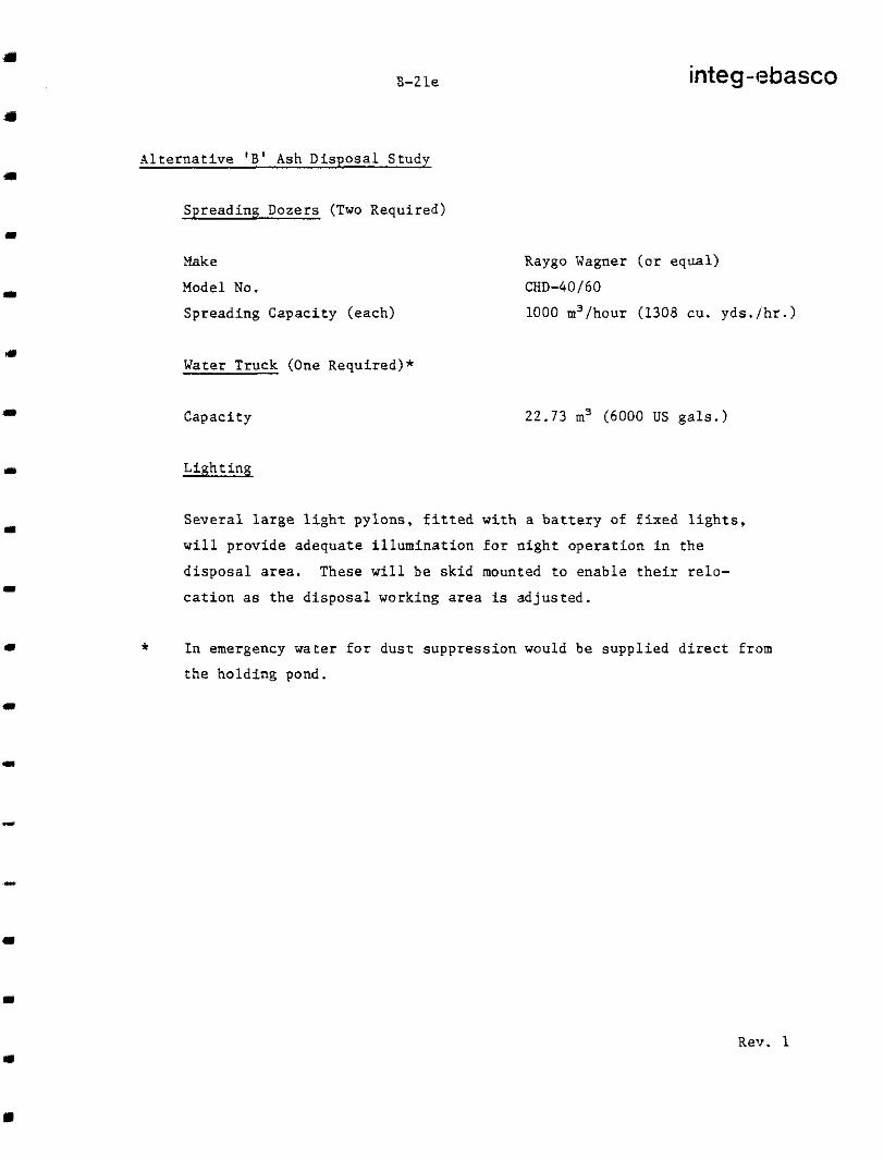
Spreading Dozers (Two Required)
Make
Model No.
Spreading Capaci ty (each)
Water Truck (One Required)*
Capaci ty
integ-ebasco
Raygo Wagner (o r equa l )
CHD-40/60
1000 m3/hour (1308 cu. y d s . / h r . )
22.73 m3 (6000 US g a l s . )
L i g h t i n g
S e v e r a l l a r g e l i g h t p y l o n s , f i t t e d w i t h a b a t t e r y o f f i x e d l i g h t s ,
w i l l p r o v i d e a d e q u a t e i l l u m i n a t i o n f o r n i g h t o p e r a t i o n i n t h e
d i s p o s a l area. These w i l l be sk id mounted t o e n a b l e t h e i r r e l o -
c a t i o n as the d i sposa l work ing area is ad jus t ed .
* I n emergency water f o r d u s t s u p p r e s s i o n would be suppl ied direct f rom
the holding pond.
Rev. 1

B-22 integ-ebasco
A l t e r n a t i v e ' B ' Ash Disposal Study
The f i n a l d i s t r i b u t i o n p l a n will b e s u b j e c t t o a d e t a i l e d s u r v e y o f t h e
d i s p o s a l area a f t e r r e m o v a l o f v e g e t a t i o n , t o p s o i l , e t c . , c r e e k d i v e r s i o n
and d r a i n a g e r e q u i r e m e n t s , d e f i n i t i v e a s h p r o d u c t i o n r a t e s , a s h c h a r a c -
ter is t ics , dozing and compact ion data and equipment and methods proposed
by m a n u f a c t u r e r s a t t h e b i d d i n g s t a g e . I t i s e x p e c t e d t h a t t h e f i n a l
d i s t r i b u t i o n p l a n will be determined and monitored from studies of both
a p h y s i c a l model and a computer model.
3.2.1.3 Reclamation
As soon as f ina l e leva t ion has been reached approximate ly two feet o f
t o p s o i l (removed from t h e b o t t o m a n d s l o p e s o f t h e d i s p o s a l a r e a p r i o r
t o p l a c i n g o f a s h ) will b e u s e d f o r t o p p i n g o f f t h e a s h p i l e . T h i s will
b e s e e d e d t o p r e v e n t e r o s i o n o f t h e t o p s o i l . S h o u l d t h e amount o f t op -
s o i l c o l l e c t e d from t h e d i s p o s a l a r e a n o t b e s u f f i c i e n t t o c o v e r t h e a s h
p i l e , s o i l f rom o the r a r eas will b e r e q u i r e d .
I t i s a l s o n o t e d t h a t r e c l a m a t i o n o f t h e d r y a s h d i s p o s a l a r e a i n Alter-
n a t i v e ' B ' i s e f f e c t e d d u r i n g t h e o p e r a t i n g l i f e o f t h e p o w e r p l a n t a n d
the p rocess i s grea t ly s impl i f ied in compar ison wi th the ash ponds o f the
Base Scheme and A l t e rna t ive ' A ' . With an ash pond f r e e s t a n d i n g water must
be removed and/or evaporated before the area can be covered with a s u i t , i b l e
topping material. With a s i n g l e p o n d , r e c l a m a t i o n c o u l d n o t b e i n i t i a t e d
be fo re t he p ro j ec t ' s decommiss ion ing phase .
3 . 2 . 2 Technical Data
3 . 2 . 2 . 1 Ash Bulk Densi ty
Fly A s h : Loose, d r y b a s i s 0 . 8 0 tonnes /m3 (50 lbs . /cu . f t . ) Compacted, dry basis 1 .28 tonnes/m3 (SO l b s . / c u . f t . ) Conditioned, 20% H 2 0 Compacted, 20% H 0
0.96 tonnes/m (60 lbs . /cu . f t . ) 1.54 tonnes/m3 (96 l b s . / c u . f t . )
Bottom Ash: Loose, d r y b a s i s 0.SO tonnes/m3 (50 l b s . / c u . E t . ) Compacted, dry basis 1.28 tonnes/m3 (SO I b s . / c u . f t . ) Condi t ioned, 40% Hz0 1 . 1 2 tonnes/m3 (io l b s . / c u . f t . ) Compacted, 40% H20 1.79 tonnesim (112 l b s . / c u . f t . )
3
2 3
Ash M i x t u r e : ( 5 5 % f l y a s h p l u s 45% bottom ash)* Loose , d ry bas i s 0 .80 ' t onnes /m, (50 l b s . / cu . f t . ) 3
Compacted, dry basis Condi t ioned, 29% Hz0
1.25 tonnes/m; (SO I b s . / c u . f t . )
Compacted, 29% H20 1.03 t o n n e s / m ( 6 4 . 3 l b s . / c u . f t . ) 1.65 tonnes/m3 (103 I b s . / c u . f t . )
* \\'orst c o n d i t i o n f o r a s h t r a n s p o r t a t i o n a n d d i s p o s a l .

B-23
~~ ~~
integ-ebasco
A l t e r n a t i v e ' B ' Ash Disposal Study
3.2.2.2 Annual Ash Product ion
(Based on B . C . Hydro Operating Regime da ted 31 May, 1978)
r-
Year
1 2 3
4
5
6 - 15 16 - 25 26 - 35 35 y e a r Total
Annual Ash Product ion Annual Average
ulk %=.Ea,: Dry-Loose
Tonnes
390,000 780,000
1,410,000
2,120,000 2,700,000
3,?90,000
3,055,000 2,585,000
96,700,000'
Bulk SG =1.0 Conditionec
Tonnes
503,000 1,006,000 1,819,000
2,735',000
3,483,000 4,244,000 3,941,000
3,335,000
124,746,000
Compacted I Conveying
I 7 i
I
609,000 1,102,000
1,656,000
2,109,000 2,570,000 484 2,3S7,000 450 2,020,000 381
5,551,000
Annual"" Average
Disposal Rat e
m3/day
1,356 2,671 4,829 7,260
9,247 11,267 10,462 8,853
For conveyor design purposes an average hourly conveying ra te of 774 tonnes/hour was used. *** This r e f l ec t s t he wors t cond i t ions a s fo l low: ; :
- Boiler f i r i n g w o r s t c o a l
- Turbine valves wide open (VIVO) r a t i n g
- Bottom a s h / f l y a s h g r a v i m e t r i c s p l i t 45/55 - 40% water content in bot tom ash****
- 20% w a t e r c o n t e n t i n f l y a s h .
* C a l c u l a t i n g t h e l i f e t i m e d r y a s h p r o d u c t i o n s by t h e a l t e r n a t i v e
method of a p p l y i n g t h e l i f e t i m e a v e r a g e c a p a c i t y f a c t o r (65%) t o
t h e f u l l l o a d a s h p r o d u c t i o n r a t e g i v e s 107,000,000 t o m e s .
* * Conditioned.
* * * T h i s r a t e was c a l c u l a t e d on t h e b a s i s o f maximum t o t a l a s h p r o -
d u c t i o n o f 166.6 kg/s (wors t condi t ion , 4 u n i t s o p e r a t i n g )
**** Average i s 3 0 % , wors t condi t ion i s 4006.

n
1)
I
I
B-24 integ-ebasco
A l t e r n a t i v e 'B' Ash Disposal Study
- Cond i t ioned f l y a sh , 5 5 % : 166.6 x . 5 5 x 1 . 2 (2OnO "0) = 110 k g / s
- Dewatered bottom ash, 4 5 % : 166.6 x .45 x 1 . 4 (40's H 0) = 105 kg/s
Tota l = 215 k g j s 2 -
= 7 7 4 tonnes/hour
The conveyor des ign capac i ty is 10% above the maximum a s h p r o d u c t i o n r a t e
t o a l l o w f o r s u r g e s i n a s h p r o d u c t i o n .
3.2.3 Labour Requirement
3 .2 .3 .1 Opera t ing S t a f f
The no rma l eve ryday ope ra t ion o f t he a sh t r anspor t a t ion , d i s t r ibu t ion
and compaction system will r e q u i r e a t o t a l crew of 7 p e r s h i f t d i s t r i b -
u t e d as f o l l o w s :
Conveyors 1014 and B - one o p e r a t o r , o n e h e l p e r
Conveyors 102A and B I Conveyors 103A and B}- t h r e e o p e r a t o r s , one h e l p e r
Conveyors 104A and B}
Spreader dozer - one o p e r a t o r .
When conveyors 1024 o r B must be moved, shortened o r lengthened an
e x t r a crew of two o p e r a t o r s and two h e l p e r s w i l l be needed for approx-
imate ly 1 -3 sh i f t s depending on the complex i ty o f t he move. The
frequency of moves will vary ; moves will b e m o r e f r e q u e n t i n i t i a l l y
when the equipment i s working i n t h e c o n f i n e d a r e a o f t h e c r e e k b o t t o m .
Later when the ash can be spread over a l a r g e l e v e l a r e a t h e n e e d f o r f requent moves will be reduced. From time t o t i m e when dus t ing neces -
s i t a t e s t h e u s e o f a wa te r t ruck , a t r u c k d r i v e r will a l s o b e r e q u i r e d .
3 .2 .3 .2 Main tenance S ta f f
One e lec t r ic ian and one mechanic , bo th opera t ing ou t o f the power
p l a n t m a i n t e n a n c e f a c i l i t i e s , would b e r e q u i r e d f o r t h e t r a n s p o r t
conveyors and d i s t r ibu t ion /equ ipmen t . Fu l l u t i l i za t ion cou ld be
achieved by ex tending the du t ies o f th i s main tenance c rew outs ide
t h e a s h t r a n s p o r t a t i o n / d i s p o s a l s y s t e m .
3 .2 .4 A l t e rna t ives
Tne "Evaluation of Continuous Bottom Ash Removal Sys tem Incorpora t ing

B-25 integ-ebasco
A l t e r n a t i v e 'B' Ash Disposal Study
a Drag Bar Conveyor f o r Hat Creek Power Plant" by Integ-Ebasco of May
1978 compared two t ranspor t sys tems, be l t conveyors and t rucks f o r
t h e d r y a s h d i s p o s a l scheme a t Upper Medicine Creek Valley. For t h i s
case the be l t conveyor sys tem was i n d i c a t e d t o b e more economical
than the t rucking sys tem. For t h e d r y d i s p o s a l scheme a t Mid !4edicine
Creek Valley it i s assumed t h a t t h e b e l t c o n v e y o r s y s t e m would have
t h e same economic advantage and therefore no f u r t h e r c o n s i d e r a t i o n
has been g iven to a t rucking sys tem.
The p o s s i b i l i t y o f a s ingle t ransport conveyor complete with emergency
s tockpi le equipment for 2 -3 days ash p roduct ion was c o n s i d e r e d i n l i e u
o f two 100% capaci ty conveyors . Whereas s p e c i f i c c o s t s h a v e n o t b e e n
e s t a b l i s h e d , e n g i n e e r i n g j u d g e m e n t i n d i c a t e s t h i s a l t e r n a t i v e t o b e
uneconomic. The s a v i n g s i n c a p i t a l c o s t s of one conveyor i s reduced
by t h e i n c r e a s e d c a p a c i t y o f a s ing le conveyor t o ca t ch up a f te r a
p e r i o d o f u n a v a i l a b i l i t y a n d a l s o by t h e c o s t o f t h e s t o c k o u t and
reclaim equipment . Operat ing costs would a l so be h ighe r due t o doub le
h a n d l i n g t h e a s h . I n a d d i t i o n a s i n g l e c o n v e y o r p r e c l u d e s t h e p o s s i b i l -
i t y o f t r a n s p o r t i n g b o t t o m a s h a n d f l y a s h s e p a r a t e l y f o r t h e p u r p o s e of
bu i ld ing t he d ra inage l aye r s o f bo t tom a sh i n t h e ash p i l e unless bottonl
a s h s t o r a g e s i l o s are i n s t a l l e d .
3 .2 .5 Tes t s - I t should be no ted tha t th i s des ign concept has been deve loped wi thout
t he bene f i t o f any da t a o r t e s t work r e s u l t s i d e n t i f y i n g t h e p h y s i c a l
p r o p e r t i e s a n d h a n d l i n g c h a r a c t e r i s t i c s s p e c i f i c t o t h e Hat Creek coal
ash a t va r ious mo i s tu re con ten t s and unde r va ry ing c l ima t i c cond i t ions .
For the purpose o f th i s concept it has been assumed that the ashes can
b e h a n d l e d e f f e c t i v e l y by an a r rangement o f conveyors a t the condi t ions
e n c o u n t e r e d i n t h e Hat Creek area. However, b e f o r e f i n a l a s s e s s m e n t
o f t h i s a s h d i s p o s a l a l t e r n a t i v e t h e fo l lowing bas i c t es t work i s recommended for representat ive samples of Hat Creek coal ash:
- A t t e r b e r g limits (on f l y a s h )
- Grain s ize d i s t r i b u t i o n ( f l y a s h and bottom ash)

8-26 integ-ebasco
A l t e r n a t i v e ' B ' Ash Disposal Study
- Optimum d e n s i t y t e s t s f o r f l y a s h , b o t t o m a s h a n d f o r d i f f e r e n t
mix tu res o f bo th i n l oose and f rozen fo rms .
- Permeabi l i ty tes ts f o r b o t h l o o s e and compacted f l y a s h , b o t t o m
a s h a n d f o r d i f f e r e n t m i x t u r e s o f b o t h
- Flow m o i s t u r e p o i n t
- Heat of hydra t ion tes ts
- D i r e c t or t r i a x i a l s h e a r t e s t s
- F r e e z i n g t e s t s on f ly ash , bo t tom ash and on d i f f e r e n t m i x t u r e s
of both - a l l a t vary ing mois ture conten t and dura t ion
- Any o t h e r tests ind ica t ed f rom the r e su l t s o f above t e s t work .
(A t e s t i n v o l v i n g t h e movement of ash samples by be l t conveyors
under normal and f reezing condi t ions should give a good impressicn
o f t he p rac t i ca l p rob lems wh ich may be encountered.)
- S t a b i l i t y o f mixed bottom ash and f l y a s h i n t h e c o n f i g u r a t i o n
p r o p o s e d f o r a s h d i s p o s a l i n M e d i c i n e Creek Valley.
3.2.6 Disposal Area Configuration
3.2.6.1 Required Capaci ty
The mine was te and ash d i sposa l a rea will be contained by the makeup
w a t e r r e s e r v o i r dam ( a x i s 38 a s d e f i n e d i n HEDD Report No. 916) on t h e
east , t h e mine waste embankment on t h e west, and the Medicine Creek
Va l l ey s lopes on the no r th and sou th s ides . The r e q u i r e d c a p a c i t y o f
t h e t o t a l d i s p o s a l a r e a i s based on t h e f o l l o w i n g :
Mater ia l
1. Bottom ash and f l y a sh
3 Volume, m
( r e l a t i v e d e n s i t y = 1.28 Mg/m ). . . . . . . . 83.5 x 10
2 . Mine waste ( total volume = 139.55 x 10 m )
3 6
6 3
G r a n u l a r s u r f i c i a l s i n embankments
(0% swell f a c t o r ) . .. . . .. . 26.2 x 10
Bedrock and s u r f i c i a l w a s t e s (139.55 - 26.2) x lo6 x 1 . 2 5
(25% swell f a c t o r ) . .. . . . . .
6
6 141.7 x 10
TOTAL 251.4 x 10 6

B-2 7 integ-,ebasco
A l t e r n a t i v e ' B ' Ash Disposal Study
3 .2 .6 .2 Su r face P ro f i l e
D u r i n g t h e i n i t i a l 15 y e a r s of power p l a n t o p e r a t i o n , t h e f i n i s h e d R 1
s u r f a c e will be s loped a minimum of 1% t o t h e west and s o u t h . P r e c i p i t a -
t i o n and r e s e r v o i r s e e p a g e w i l l be hand led a s desc r ibed i n Sec t ion
3.5.5. The s lope to the south is proposed to diver t runoff and snowmelt:
away from the ash and mine waste conveyors operat ing and access areas.
On t h e n o r t h s i d e o f t h e d i s p o s a l area no waste m a t e r i a l s will b e
d e p o s i t e d o v e r t h e r e s e r v o i r o u t l e t c o n d u i t t o ease inspec t ion and
maintenance. The conduit will b e b u r i e d j u s t b e l o w t h e d e p t h r e q u i r e d
f o r f r o s t p r o t e c t i o n .
The l o w e r p a r t o f t h e d i s p o s a l area w i l l be s loped 5% as shown on t h e
Dwg. BCH 0064 SK 151. The c a p a c i t y of t h e d i s p o s a l area can be
inc reased by r a i s i n g t h e mine waste embankment a n d f i l l i n g t h e area up
t o the minimum s l o p e of 1% i f so r equ i r ed . Add i t iona l d i sposa l vo lumes
may b e r e q u i r e d d u e t o less densely compacted ash d u r i n g f r e e z i n g
c o n d i t i o n s a n d / o r d u e t o ash/mine waste volumetr ic p roduct ion be ing
h i g h e r t h a n a n t i c i p a t e d .
3 . 2 . 6 . 3 D i s p o s a l P i l e D r a i n a z e and S t a b i l i t y
Lined drainage courses w i l l be provided a t the bottom and sides of t h e
d i s p o s a l area and a l s o w i t h i n t h e p i l e (as shown on SK 151) t o p r e v e n t
excessive accumulat ion of water a n d c o n s e q u e n t i a l p i l e i n s t a b i l i t y .
The s t r i p p e d s u r f a c e of t h e d i s p o s a l area w i l l b e g l a c i a l till o r
o t h e r f a i r l y impermeable surface. Bottom ash i n the a s h d i s p o s a l a r e a
and s u i t a b l e f i l t e r material i n t h e mine waste area will be depos i ted
a g a i n s t th is s u r f a c e . A t s p e c i f i e d v e r t i c a l intervals within t h e a s h
p i l e a l ternate c o u r s e s o f f l y a s h and bot tom ash w i l l p rovide l ined
d ra inage cour ses - t h e f l y a s h l a y e r f o r m i n g t h e l i n i n g and the bot tom
a s h p r o v i d i n g t h e d r a i n a g e c o u r s e . S t a b i l i t y a n a l y s e s of t h i s scheme
w o u l d b e c a r r i e d o u t i n t h e d e t a i l e d e n g i n e e r i n g p h a s e .
Rev. 1

B-25
-
integ-ebasco
A l t e r n a t i v e 'B' Ash Disposal Study
3 . 2 . 6 . 4 Roads - A road of varying widths and des ign will be cons t ruc ted f rom the power p lan t
a r e a t o t h e r e s e r v o i r makeup water pumphouse. Between the power p lan t and
t h e f i r s t c o n v e y o r u n d e r p a s s it will s e r v e p r i m a r i l y as the conveyor sei-vice
road. From t h i s u n d e r p a s s t o t h e p r o j e c t a c c e s s r o a d it will be designed
as the p l an t access road . From t h e p r o j e c t a c c e s s r o a d t o t h e f i x e d c o n v e y o r
t r a n s f e r p o i n t it will s e r v e p r i m a r i l y a s t h e c o n v e y o r s e r v i c e r o a d . In t h i s p o r t i o n t h e r o a d will have i t s m a x i m u m s l o p e o f 1 5 % . The remainin::
p a r t o f t h e r o a d will lead t o t h e makeup water pumphouse.
Because o f t he r e loca t ion o f t he makeup w a t e r r e s e r v o i r t h e p r o j e c t a c c e s s
road rou t ing may have t o b e m o d i f i e d . T h i s s u b j e c t i s n o t i n c l u d e d i n t:he
scope of t h e p r e s e n t s t u d y .
3 . 2 . 7 Operating Experience - Dry Ash Disposal Areas
The f o l l o w i n g s t a t i o n s d i s p o s e o f a l l o r p a r t o f t h e i r f l y a s h and bottom
ash p roduc t ion i n d r y d i s p o s a l a r e a s :
U t i l i t y
A l b e r t a Power Limited
Calgary Power Limited Arizona Public Service
Southern Cal i forn ia Edison
Columbus and Southern Ohio
P h i l a d e p h i a E l e c t r i c
Duquesne L igh t (P i t t sbu rgh)
Pennsy lvan ia E lec t r i c
Appalachian Power Company
S t a t i o n
Battle River
Sundance Four Corners
Mo j ave
Conesvi l le
Cromby (bottom and f l y a s h )
Eddystone
Elrama (bottom and f l y a s h )
Cheswick
Conemaugh
Cl inch River ( f ly ash)
J. Amos ( c o n v e r s i o n t o d r y d i s p o s a l
f o r f l y a s h )

.
'.. . ..
..
7-
.

B-30 integ-ebasco
A l t e r n a t i v e 'B' Ash Disposal Study
3.3 Makeup Water Pumphouse and Pipel ine (see Drawings BCH 0064 SK 156, 157 and 158)
The pumphouse will b e l o c a t e d w i t h i n t h e r e s e r v o i r a r e a a b o u t 60 m from
i t s north bank. I t will c o n s i s t o f a v e r t i c a l 3.05 x 6 . 1 m conc re t e st,aft about 35 m i n h e i g h t w i t h r e c t a n g u l a r o p e n i n g s a t i t s base and a s t e e l
f r a m e d b u i l d i n g w i t h i n s u l a t e d s i d i n g . The b u i l d i n g will be approximate ly
4 .9 x 7 . 3 m i n s ize and will be connected to the access road by a conc re t e
b r idge . The b a s e e l e v a t i o n s a r e a s f o l l o w s :
Opera t ing Floor Level : E l . 1245 m
P.M.F. Level : 1242.5 m Normal High Water Level: 1230 m Minimum Low Water Level: 1215 m
The pumphouse will h a v e t h r e e ( 3 ) 50% du ty , mu l t i - s t age ve r t i ca l pumps ,
each of about 0 .63 m / s (10,000 gpm) capac i ty and wi th a motor of approx-
ima te ly 2000 kW (2680 hp). The pumps will supp ly wa te r t o t he coo l ing t ower
bas in channel a t an approx ima te e l eva t ion o f 1410 m . The pump impello:: and
shaf t assembly will b e i n s t a l l e d i n a p p r o x i m a t e l y 3 m long sec t ions . ?4otors
will b e i n s t a l l e d 0 . 1 5 m above t he ope ra t ing f l oo r . Pumps and motors will
be serviced by an o v e r h e a d b r i d g e t y p e e l e c t r i c a l l y o p e r a t e d c r a n e o f :I2 Mg
capaci ty and 4 .27 rn span. The access b r idge will be designed f o r the : se rv ice
t ruck l oads . Dur ing f r eez ing wea the r i c ing i n any nonopera t ing pump s h a f t w i l l be prevented by a compressed a i r b u b b l e r s y s t e m (see r e f e r e n c e 2 8 : ) .
3
Excavat ion for t h e pumphouse will b e u s e d i n t h e c o n s t r u c t i o n o f t h e
r e s e r v o i r dam a s t h i s area h a s b e e n d e s i g a t e d a s a bor row a rea for
impervious core material. Volume of compacted b a c k f i l l f o r f o u n d a t i o n : ;
o f t he access b r idge i s n e g l i g i b l e . An a l t e r n a t i v e a r r a n g e m e n t w i t h t h e
pumphouse l o c a t e d on t h e bank and intake pipes a t the bot tom (Scheme 2'1
was cons idered . I ts c o s t d i f f e r e n t i a l o v e r t h e recommended scheme (Scheme
1) i s cons ide rab le as shown i n t h e f o l l o w i n g t a b l e . S i n c e t h e s a v i n g ; l s i n g
Scheme 1 c o u l d b e a p p l i c a b l e f o r b o t h r e s e r v o i r l o c a t i o n s , t h e d i f f e r e n t i a l
c o s t i s excluded from the economic comparison of t h e a l t e r n a t i v e a s h
disposal schemes.

DIFFERENTIAL c o s COMPARISON OF SCHEMES TAB LE :
Item
1. Excavat ion i n 'Till
2 . Excavat ion i n Rock
3 . Backfi l l
4 . C o s t o f a c c e s s b r i d g e
5. Cost of 31
i n t a k e p i p e s 1200 11un d i a .
6 . Cost of 700 nun d i a . d i s c h a r g e p i p e
SCHEME 1 SCllEME 2 Unit Unit
Quant i ty Unit P r i ce Cost Quant i ty Uni t Price Cost $ $
36,000 m 3.00 3
2 m 1700.00
- -
m 450.00
108,000 70,000 m 3.00 210,000 3
400
23,400
$219,800
Note : D i rec t cos t s on ly .
70,000 m 19.00 1,330,000 3
3 100,000 m 6 .00 600,000
170
-
m 600.00 102,000

8-32 integ-ebasco
A l t e r n a t i v e ' B ' Ash Disposal Study
3 . 3 . 2 P i p e l i n e
The makeup w a t e r p i p e l i n e will be a 711 m (28 i n . ) d i a m e t e r s t e e l p i p e
about 4 . 5 km long and will run underground along the pumphouse access
and ash conveyor service road. The maximum v e l o c i t y i n t h e p i p e l i n e
will be about 3 m/s (10 f p s ) . Along the access b r idge t he p ipe will
be s u i t a b l y i n s u l a t e d . The r e m a i n i n g p a r t o f t h e p i p e l i n e w i l l be
b u r i e d 2 m below ground l e v e l . I t w i l l b e l a i d on t h e e a s t s i d e o f
the road . Dur ing the de ta i led engineer ing phase o f the p ro jec t cons id-
e r a t i o n may be g iven t o t he p rov i s ion o f two p a r t i a l c a p a c i t y p i p e l i n e s - one a long the access road and the o the r a long a s e p a r a t e d i r e c t r o u t e .
A waterhammer a n a l y s i s would be r e q u i r e d i n t h e d e t a i l e d e n g i n e e r i n g
p h a s e t o c h e c k t h e p i p e s i z e , w a t e r v e l o c i t y and s u r g e p r e s s u r e s .

I


integ-ebasco
B-33
A l t e r n a t i v e 'B' Ash Disposal Study
3.4 IVater Q u a l i t y
The m a j o r e f f e c t o f t h i s d e s i g n a l t e r n a t i v e on power p l a n t makeup water
q u a l i t y s t e m s f r o m t h e l o c a t i o n o f t h e makeup w a t e r r e s e r v o i r . P r e v i o u s
wa te r ba l ance and water t rea tment scenar ios were so le ly based on Thompson R i v e r w a t e r q u a l i t y . With t h e r e s e r v o i r l o c a t e d i n u p p e r
Medicine Creek, 3.95 x 10⁶m3 of bledicine Creek water could enter
t h e r e s e r v o i r on an average annual basis . The c r e e k ' s w a t e r q u a l i t y
i s g r e a t l y i n f e r i o r t o t h a t o f t h e Thompson R i v e r , e x h i b i t i n g e l e v a t e d
c o n c e n t r a t i o n s o f most major parameters , espec ia l ly to ta l d i sso lved
s o l i d s (TDS) a n d a l k a l i n i t y . A v a r i a n t w a t e r b a l a n c e i s i l l u s t r a t e d
i n I n t e g - Ebasco drawing BCH 0064-SK153 Rev. B. This v a r i a n t
water balance based on Case 4 assumes a 1 .5 x 106m3/year diversion
o f Medicine Creek water f o r o t h e r u s e s ( e . g . i r r i g a t i o n ) , a n d r e s u l t s
i n an improvement in t he r e se rvo i r wa te r qua l i t y i n compar i son t o Case 4 in t h i s s t u d y .
1
I t i s recommended t h a t t h e power p l an t des ign cu r ren t ly be based
on t h e more conse rva t ive wa te r qua l i t i e s and f l ows ca l cu la t ed fo r t he
condi t ion in which no d ive r s ion ex i s t s . Shou ld t he d ive r s ion be
i n c o r p o r a t e d i n t h e p r o j e c t ' s f i n a l d e s i g n , t h e a c c u r a c y o f t h e b a s e
i n f o r m a t i o n a v a i l a b l e a t p r e s e n t would no t war ran t des ign ing t o the v a r i a n t of Case 4 .
3 . 4 . 1 Methods Used and Resul ts
To determine an average monthly and average year ly water qual i ty for
Medicine Creek, a Flow v . TDS r e l a t i o n s h i p ( a l g o r i t h m ) was developed
based on s ix months of available hiedicine Creek data. Average monthly
flows (volumes) generated by B . C . Hydro' were then u t i l i z e d t o p r e d i c t
a s s o c i a t e d TDS values . Major ions were es t imated by developing an
RZ
average TDS v . parameter ra t io based on t h e a v a i l a b l e d a t a a n d a p p l y i n g
it t o t h e p r e d i c t e d TDS va lues . Conduc t iv i ty was es t imated by apply ing
Rev. 2

integ-ebasco
6-33a
a developed Conduct iv i ty v . TDS algori thm and pH was e s t i m a t e d by
nomographic method 2 assuming carbon dioxide concentrat ions and
u t i l i z i n g Hat Creek water temperature data. The r e s u l t s o f t h e s e
a n a l y s e s a r e p r e s e n t e d i n T a b l e 1.
A s e r i e s of monthly mass balances was then performed to develop
r e a s o n a b l e e s t i m a t e s o f t h e t e m p o r a l v a r i a t i o n i n w a t e r q u a l i t y
o f t h e r e s e r v o i r . The a n a l y s e s u t i l i z e d t h e f o l l o w i n g d a t a s o u r c e s :
1. Monthly Thompson R ive r wa te r qua l i t y3
2 . Hat Creek Project Construct ion and Operat ing Schedules 4 , 5
3 . A n t i c i p a t e d power p l a n t c a p a c i t y f a c t o r s 6 , a n d
4 . Medic ine Creek reservoi r des ign charac te r i s t ics ’ .
An i n i t i a l r e s e r v o i r w a t e r q u a l i t y was developed given t h a t t h e
Thompson River makeup water system would be f u l l y o p e r a t i o n a l i n
J u l y 19844.5 and assuming t h a t t h e r e s e r v o i r would be kept empty
u n t i l t h i s time by pumping any accumulated water to the Medicine
Creek dra inage cana l . when power p l a n t demand was e v a l u a t e d , it
was assumed t h a t t h e Thompson River
Rev. 2

L B-34 inteq-ebasco - A l t e r n a t i v e ' B ' Ash Disposal Study
makeup water sys tem would main ta in the reservoi r a t i t s o p e r a t i n g c a p a c i t y ,
8.0 x l o 6 m3, i f Medicine Creek's inflow was i n s u f f i c i e n t t o do so .
Power p l a n t demand was a l s o c a l c u l a t e d on a monthly basis account ing
f o r the commissioning and commercial service phases of each unit and
t h e v a r i a b i l i t y o f t h e r e s e r v o i r ' s w a t e r q u a l i t y . This l a t t e r p o i n t
a f f ec t ed t he coo l ing wa te r sys t em ' s maximum pe rmis s ib l e cyc le o f
c o n c e n t r a t i o n which t h e r e f o r e had t o be ca lcu la ted for each month ly
i t e r a t i o n . The r e s u l t a n t r e s e r v o i r w a t e r q u a l i t y d e t e r m i n a t i o n s f o r t h e
f i r s t f i f t e e n y e a r s o f power p l an t ope ra t ion a r e p re sen ted i n Tab le 2 .
Three addi t iona l ana lyses were also performed to determine a "worst
ca se" wa te r qua l i t y f o r u s e i n power p l a n t f a c i l i t y d e s i g n : t h e e f f e c t
o f the p robable maximum f lood on r e s e r v o i r w a t e r q u a l i t y a n d t h e e f f e c t
of Thompson River makeup water sys tem inopera t ion for 40 and 70 day
p e r i o d s (25 March t o 5 May and 25 March t o 5 June r e spec t ive ly ) . Thess
p e r i o d s o f i n o p e r a t i o n a r e c o n s i s t e n t w i t h p rev ious s tud ie s of power
p l a n t makeup water requi rements and reservoi r drawdown l e v e l s . The
r e s u l t s o f t h e s e a n a l y s e s a r e p r e s e n t e d i n T a b l e 3 . The w a t e r q u a l i t y
va lues p re sen ted fo r t he "wi th t he d ive r s ion" ca ses r e f l ec t Beak Con-
s u l t a n t s Ltd.' e s t imates o f the Medic ine Creek d ivers ion capac i ty .
T h e i r r e p o r t s t a t e s t h a t o n l y t h e t o p m o s t 1 5 . 3 kmZ of Medicine Creek's
t o t a l d r a i n a g e a r e a ( 5 8 . 2 km ) IS a f f e c t e d by t h e d i v e r s i o n . This c o u l d r e s u l t i n a 26 percen t r educ t ion o f Med ic ine Creek ' s i n f low to
t h e r e s e r v o i r . This va lue was u t i l i z e d b e c a u s e i t was more conservat i .Je
than B . C . Hydro ' s es t imate o f a 38 pe rcen t vo lumet r i c r educ t ion (1 .5 x 10 m p e r annum) .
8
2 .
6 3 10
Another water qua l i ty modi f ica t ion c rea ted by the new r e s e r v o i r l o c a t i , m
concerns the amount of accumulated sediment. Because the upper bfedici:le
C r e e k r e s e r v o i r l i e s w i t h i n a n a t u r a l d r a i n a g e b a s i n , i t will be subjec . t to
na tura l sed iment loads . Due t o t h e s u b s t a n t i a l d e t e n t i o n time provide(j by
t h e r e s e r v o i r , most of t h e s e s o l i d s will accumulate on t he r e se rvo i r bo t tom.
Suspended so l ids concent ra t ions for Medic ine Creek a re no t p resent ly k.mwn.
If cor responding Hat Creek d a t a 1s u t i l i z e d and a bulk dens i ty o f 801 kg/m3
i s assumed, then accumulations o f approximately S O i m / y r can be a n t i c i p a t e d .
9 .
3

E-35 integ-ebasco
A l t e r n a t i v e ' B ' Ash Disposal Study
This would r e s u l t i n a to ta l accumula t ion of 14 ,249 m ove r t he 35 yea r
p l a n t l i f e . Also , dur ing f r e she t , e l eva ted suspended so l id s concen t r a t ions
p o s s i b l y up t o 300 mg/19, cou ld be expe r i enced i n t he p l an t ' s makeup l i n e .
Th i s cou ld a f f ec t t he aux i l i a ry coo l ing sys t em.
3
3.4.2 Water Quality Summary and Recommendations
Power p l a n t makeup water qua l i ty es t imates have been genera ted for the
l i f e o f t h e power p l a n t . As t h e t a b l e s d e n o t e , r e s e r v o i r w a t e r q u a l i t y
v a r i a t i o n s will b e e x t e n s i v e . Due t o t h e d i f f e r e n c e s i n w a t e r q u a l i t y
between the two wa te r bod ie s , any ope ra t iona l ac t ion dec reas ing power
p l an t wa te r r equ i r emen t s , e .g . r educ ing t he power p l a n t c a p a c i t y f a c t o r ,
ex tended un i t shutdown, e tc . , will d e t e r i o r a t e r e s e r v o i r w a t e r q u a l i t y .
Based on t h i s f a c t t h e d a t a p r e s e n t e d i n Column 3 of Table 3 should be
u t i l i zed fo r wa te r t r ea tmen t f ac i l i t y des ign . Th i s r ecommenda t ion supposes
t h a t s u c h a mode of opera t ion could be implemented t o m i t i g a t e p o s s i b l e
impacts on andromous salmonids and that the water qual i ty effects o f Thomp-
son River in take inopera t ion would endure longer than the 40 day shutdom
p e r i o d . The e f f e c t of t h e d i v e r s i o n must be ignored as there i s no
g u a r a n t e e t h a t i t will be in opera t ion . This recommendat ion a l so p rovides
a 10 percent design margin i n excess o f the expec ted average water qua l i ty
(Column 6 o f Table 2) which would f a c i l i t a t e normal operat ion during
d i s r u p t i v e o p e r a t i o n a l a c t i o n s o r unexpec ted wa te r qua l i t y f l uc tua t ions .
Such r e s e r v o i r w a t e r q u a l i t y f l u c t u a t i o n s c o u l d r e s u l t from r i v e r and creek qua l i t y va r i a t ions , a i rbo rne con tamina t ion , l each ing o f chemica l spec ie s
from t h e r e s e r v o i r s u b s t r a t e o r an accumulation o f o r g a n i c m a t e r i a l . The
water t reatment system must a lso be capable of handl ing extreme water
q u a l i t y v a r i a t i o n s d u r i n g t h e f i r s t t h r e e y e a r s o f o p e r a t i o n (Columns 2
and 3 of Table 2) and the an t i c ipa t ed "wors t ca se" wa te r qua l i t y occu r r ing
during a 70 day makeup water sys tem inopera t ion per iod . The probable
maximum f lood (Column 6 of Table 3) will n o t g r e a t l y a f f e c t r e s e r v o i r w a t e r
q u a l i t y o r p l a n t o p e r a t i o n i f t h i s recommendation i s implemented.
.~ .

"
Jau. ~
248
378
45
I 8
1.8
8.7
0 .35
18
8 . 8
0 .2
I 9 8
25
8 .6
11.1135 ~-
__ "
Feb.
2 4 5
374
4 4
18
1 . 7
8.6
0.34
17
n.7
0 . 2
195
25
8.6
0 . us9 ~.
___ Mar. __
237
361
4 3
1 7
1 . 7
8.3
0.33
1 7
8 . 4
0.2
189
24
8.6
0.115 ~
__ "
Apr .
215
125
39
16
1.5
7 .5
0.30
15
7.6
0.2
171
22
8 . 6
"
0.105
"
Nay __ 179
266
32
1 3
1 . 3
6.3
0.25
13
6 . 4
0.2
143
I n
8.6
0 .33 " .
~. .lune ""
167
247
.? n I 2
1 . 2
5.8
11.23
12
6.0
0.2
I 3 3
17
8 . 6
11.492 " ~
__ "
July
197
296
35
15
1 . 4
6 . 9
0.28
14
7.0
0 .2
157
20
&.6
0.184 __
__ "
AUE.
231
351
42
17
1 . 6
8.1
0.32
16
8. 2
0.2
184
23
8.6
11 .01, ""
S r p t .
235
357
42
17
1.7
8.2
0.33
17
0 . 3
0.2
187
24
8 .6
0.053 -_
~
1kt . __ 234
356
42
17
1.7
8 .2
0.35
17
n.3
0 .2
187
24
8.6
0 . I156 "_
.~ No". "
235
357
42
17
1 . 7
8 . 2
11.33
17
8 . 3
0.2
187
24
8 . 6
11.115s "_
IDec .
24 3
371)
4 4
18
1.7
8 . 5
11.34
17
8 . 6
0.2
1!14
25
8 . 6
11.041
222
33h
40
16
1 . 6
7.8 m 0 . 3 1 I
w o\
I 6
7 . 9
11. 2
177
23
8.6
U.125

Parameter
C O l . (1)
Tota l Disso lved S o l i d s
Conduct iv i ty (umho/cm)
Calcium
Magnesium
Potassium
Sodium
Chloride
Sulphate
T o t a l S i l i c a (S ioz)
(Sioz) D i s s o l v e d S i l i c a
A l k a l i n i t y
TOC
pH ( u n i t s )
B-37
TABLE 2
DEVELOPED RESERVOIR WATER QUALITY
Years 1 through 3
blinimum Flaximum Col. ( 2 ) Col. (3)
87.9
141
1 7 . 1
4.5
0 .96
3.29
0.74
8.78
5.04
-
60.7
6 .1
7 .8
1 2 7 . 1
197
23.7
8 .2
1.08
4.52
1.43
10.5
5 . 7
-
95.3
13.3
8 . 3
Year 4
:o1. (4 )
89 .1
144
17 .5
4 . 6
0.99
3 . 3
1.27
8 . 9
5 . 4
-
62.4
6 . 9
7 . 7
Year 5
Col. (5)
87 .1
141
1 7 . 1
4 .4
0 .99
3 .2
1.28
8.8
5.4
-
60.7
6 . 7
7.7
INTEG-EBASCO
Years 6-15 -
Col. (6)
82.2
134
16.3
4 . 0
0 .96
3.1
1.32
8 . 5
5 .3
-
56.5
6 . 1
7 . 7
- Notes : - A l l parameters expressed in mgi l un less o therwise no ted .
- The d a t a p r e s e n t e d i n Column 6 should a lso approximate average 'water q u a l i t y f o r t h e l i f e o f t h e power p l a n t .
- The d a t a p r e s e n t e d i n Column 3 should approximate worst water qual i ty fo r wa te r t r ea tmen t sys t em des ign ( t empora ry bas i s ) .

II. a i t I t I 1 L I a L YI
TABLE 3
IIESEIIVOIR WATER OUALI'I'Y AFTEII TtIOMI'SON IIIVEII INI'AKII INOPPRATION I W R 10 AND 70 DAY PEIIIOI)S* AND WA'l'i<lI QUALITY
01' I'ROBAHLI? MAXIhtUh1 F LOUD
Parameter
Col. ( 1 ) -
Tota l Disso lved S o l i d s
Conduct iv i ty (w l lo /cm)
Calcium
Magnesium
Potassium
Sodium
Cll lor ide
Su lpha te
T o t a l S i l i c a (S i02)
(SiU2)
( a s caco )
D i s s o l v e d S i l i c a
A l k a l i n i t y
3 TOC
p l l ( u n i t s )
1 Day Per iod . th Diversion
C O l . ( 2 )
89.4
1 4 4
17.5
4 .7
0.99
3.4
1 .26
8 .9
5 .4
.
62.8
7.0
7.8
Without Diversior 40 Day Per iod
Col. ( 3 )
91.8
148
17 .9
4.9
1 .0
3.4
1 . 2 4
9 . 0
5 . 5
64 .8
7 . 3
7 .8
m m Notes: * - Assumes 4 uni ts o p e r a t i n g a t 78% c a p a c i t y f a c t o r .
~
- Al l parameters expressed i n mg/l un le s s o the rwise no ted . - 'Ihc 4 0 day per iod o f Columns 2 and 3 r e p r e s e n t s 25 March t o 5 May. - 'I'hc 70 day per iod of C o l u r ~ ~ n s 4 and 5 r e p r e s e n t s 25 March t o 5 June . - Probable Maximunl Flood volume i s 15 x 10' m3; assumed flow i s 6 m / s . 3

839 INTEG-EBASCO
ALTERNATIVE ' 6 ' ASH DISPOSAL STUDY
3.5 WATER MANAGEMENT FOR ALTERNATIVE ' B '
Under the p resen t des ign ph i l osophy , t he power p lan t was te management system i s commit ted t o o p e r a t i o n i n a "no - l i qu id d i scha rge" mode. To
e v a l u a t e t h e r e q u i r e d w a t e r management t e c h n i q u e s t o a c h i e v e t h i s
s t a t u s , i n c l u d i n g t h e p o s s i b i l i t y o f w a s t e w a t e r t r e a t m e n t and reuse,
f l ow-chemica l ba lances were deve loped fo r t w o wors t case makeup wa te r
q u a l i t y s i t u a t i o n s . 2 ' B o t h c a s e s c o n s i d e r e d h a d a v e r a g e
m e t e o r l o g i c a l c o n d i t i o n s f o r t h e p e r i o d c o r r e s p o n d i n g t o " n o r m a l w o r s t
c a s e " r e s e r v o i r w a t e r q u a l i t y w i t h t h e p o w e r p l a n t o p e r a t i n g a t 100
p e r c e n t c a p a c i t y f a c t o r , p e r f o r m a n c e b l e n d c o a l , maximum ash hopper
evapora t ion and no-1 iqu id d ischarge. "Normal Worst Case" r e s e r v o i r
q u a l i t y c o r r e s p o n d s t o t h e Thompson R i v e r s u p p l y i n o p e r a b l e f o r a 40
day per iod (co lumn 3 o f T a b l e 3 ) . Case 1 used a f l y ash/bo t tom ash
r a t i o o f 5 5 / 4 5 , w h i l e Case 2 cons ide red a f l y a s h i b o t t o m r a t i o o f 8 5 / 1 5 .
The c a l c i u m c o n c e n t r a t i o n m u s t b e m a i n t a i n e d a t a l e v e l o f l e s s t h a n
400 mg/l as Ca (1000 m g l l a s CaC03) i n t h e r e c i r c u l a t i n g c o o l i n g
water system t o p r e v e n t s c a l i n g , b a s e d o n t h e r e s u l t s o f p r e v i o u s
s t u d i e s . a ' T h i s l e v e l m u s t a l s o b e m a i n t a i n e d i n a l l s u b s e q u e n t
s y s t e m s e i t h e r b y s e t t i n g a n a p p r o p r i a t e f l o w l c h e m i c a l b a l a n c e b e t w e e n
the pr imary systems' b lowdown and secondary systems' makeup o r b y i n s e r t i n g a wastewater t rea tment sys tem fo r ca lc ium remova l a t an o p t i m a l p o i n t w i t h i n t h e o v e r a l l w a t e r management system.
R e s u l t s o f t h e s e a n a l y s e s a r e g i v e n i n D r a w i n g BCH 0064 SK 170 and
Tab le 4. B a s e d o n t h e s e f i n d i n g s a n d c u r r e n t a v a i l a b l e w a t e r q u a l i t y
data, a was tewa te r t rea tmen t / recyc le f a c i l i t y i s r e q u i r e d t o remove
s c a l e f o r m i n g c o n s t i t u e n t s . A t t h e p r e s e n t t i m e ( k c . 19€0), a
l ime-soda ash t reatment system i s recommended f o r t h i s p u r p o s e .
Changes i n c o n c e p t u a l w a t e r management p l a n s a n d f a c i l i t y d e s i y s f r o m
those p resen ted i n t h e Water Management Study- r e s u l t e d f r o m i n v e s t i g a t i n g t h e new a s h d i s p o s a l a l t e r n a t i v e t o e n s u r e a d e q u a t e
h a n d l i n g o f all wastes. The s p e c i f i c s o f each systm and assoc ia ted a s s u m p t i o n s a r e d e t a i l e d i n t h e f o l l o w i n g s e c t i o n s .
11/
Rev. 3 A o r . 1 ' 3 1

B40
INTEG-ESASCO
T A B L E 4
SUMklARY O F RESULTS*
Case 1 Case 2
Cooling Tower Makeup, l / s 1032 101 3
Cooling Tower Cycles o f
Concen t ra t ion 21.9
Cooling Tower Blowdown Calcium Concent ra t ion , mgl l Ca
Required Treatment Flow, Cooling Tower, l / s
131.0
91.5
Required Treatment Flow, Trough, 11s 169.4
Calcium Renoval Rate, Kglday 3,242
Hopper Calcium Concentration, mg11 Ca 4 0 0
Trough Calcium Concentrat ion, m g l l Ca
Surge Tank Calcium Concentrat ion, mgll Ca
20 0
157.9
*Case 1 r e p r e s e n t s maximum t r ea tmen t r equ i r emen t s .
35.9
129.2
149.1
12.3
1,642
4 0 0
t 4 0 0
303.5
Rev. 3 Apr. 198:.

84 1
INTEG-EBASCO
L
m
3.5.1 Ash Handling System
Bot tom ash will b e c o n t i n u a l l y c l e a r e d b y a drag bar conveyor and
t r a n s p o r t e d t o t h e M i d M e d i c i n e Creek d i s p o s a l a r e a i n a " d r y " s t a t e .
F l y ash, economizer ash, and a i r p r e h e a t e r ash will b e c o l l e c t e d d r y i n
s i l o s and a l s o t r a n s p o r t e d b y b e l t c o n v e y o r t o t h e a s h d i s p o s a l a r e a .
The s p e c i f i c m a j o r w a t e r use o p e r a t i o n s w i t h i n t h e a s h h a n d l i n g system will cons is t o f : ash hopper quench ing , bo t tom ash en t ra inmen t , mill
r e j e c t s s l u i c i n g , and f l y ash we t t i ng .
Quench ing wa te r f o r t he ash hopper will p r o v i d e c o n t i n u o u s c o o l i n g f o r
t h e b o t t o m a s h a n d r e f r a c t o r y w a l l s o f t h e hopDer. T h i s f l o w
requ i rement has been es t imated t o b e 42.3 l / s f o r 4 u n i t o p e r a t i o n and
was assumed t o b e i n d e p e n d e n t o f p l a n t c a p a c i t y f a c t o r . B o t t o m a s h
t r o u g h c o o l i n g w a t e r will b e r e c i r c u l a t e d . A heat exchange system will m a i n t a i n r e c i r c u l a t i n g w a t e r t e m p e r a t u r e a t a l e v e l c o n d u c i v e t o s y s t e m
component protect ion. Mill r e j e c t s will be s l u i c e d t o t h e d r a g b a r
c o n v e y o r i n t e r m i t t e n t l y . T h i s will r e q u i r e an i ns tan taneous f l ow o f
a p p r o x i m a t e l y 25 l i s p e r u n i t . S i n c e t h i s m a t e r i a l w o u l d b e composed
m a i n l y o f p y r i t i c compounds, l e a c h a t e s a r e n o t e x p e c t e d t o b e
s i g n i f i c a n t and were n o t c o n s i d e r e d i n t h e f o r m u l a t i o n o f t h e s y s t e m ' s
chemical ba lance.
F l y ash ( inc lud ing economizer and air p r e h e a t e r a s h ) w e t t i n g i s a ma jo r
p l a n t c o n s u m p t i v e water use. W e t t i n g i s r e q u i r e d t o f a c i l i t a t e ash
h a n d l i n g and compact ion, and prevent dust ing problems. Based on
performance coal and a 20 p e r c e n t w a t e r c o n t e n t ( d r y b a s i s ) f o r
adequate wet t ing, 12.9 l / s o f w a t e r f o r Case 1 and 20.0 l / s f o r Case 2 w o u l d b e r e q u i r e d a t 100 p e r c e n t c a p a c i t y f a c t o r w i t h 4 u n i t s i n
ope ra t i on . An economizer ash dry handl ing system i s p r e s e n t l y
recommended f o r t h i s w a t e r management a l t e r n a t i v e and t h e r e f o r e
p o t e n t i a l l e a c h a t e s f r o m t h i s s o u r c e h a v e been neglected. If wet
s l u i c i n g o f t h i s m a t e r i a l i s c o n s i d e r e d f o r e c o n o m i c a l r e a s o n s i n t h e
f u t u r e , a l e a c h a t e t e s t p r o g r a m s h o u l d b e p e r f o r m e d .
Rev. 2 De-. l9eo

842
INTEG-EBASCO
System consumptive water uses a l s o i n c l u d e w a t e r e n t r a i n e d i n t h e
bottom ash and ash hopper evaporat ion. The a u a n t i t y o f w a t e r e n t r a i n e d
i n t h e b o t t o m a s h h a s b e e n e s t i m a t e d t o b e 1 5 . 9 1 / s f o r Case 1 and 5.3
l / s f o r Case 2 f o r 4 u n i t s a t a p l a n t c a p a c i t y f a c t o r o f 1 0 0 p e r c e n t .
These est imates are based on per formance coal and a bo t tom ash water
c o n t e n t o f 30 p e r c e n t ( d r y b a s i s ) , w h i c h i s c o n s e r v a t i v e f r o m a water
management v i e w p o i n t . The q u a n t i t y o f w a t e r e v a p o r a t e d i n t h e a s h
hopper has been est imated t o b e 25.6 l / s f o r Case 1 and 10.2 l/s f o r
Case 2 based on a p r e l i m i n a r y e n e r g y b a l a n c e p r e p a r e d f o r t h i s s y s t e m
assuming bot tom ash cool ing f rom approx imate ly 1100'C.
The t o t a l c o n s u m p t i o n o f w a t e r i n t h e a s h h a n d l i n g s y s t e m , t h e r e f o r e ,
t o t a l s 54.4 l / s f o r Case 1 and 35.5 l / s f o r Case 2. T h i s i s
r e p l e n i s h e d t h r o u g h makeup d e r i v e d f r o m t h e w a s t e w a t e r c o l l e c t i o n sump
and comprised o f c o o l i n g t o w e r blowdown and o t h e r p l a n t w a s t e w a t e r s
( r e f e r t o D r a w i n g BCH 0064 SK 170) .
3.5.2 C i r c u l a t i n g Water System
M e d i c i n e C r e e k r e s e r v o i r w a t e r q u a l i t y (Column 6, Table 2 and Column 3, Tab le 3 ) wou ld limit r e c i c u l a t i n g w a t e r s y s t e m c y c l e s o f c o n c e n t r a t i o n
t o a maximum o f a p p r o x i m a t e l y 20 ( w i t h o u t a t r e a t m e n t l r e c y c l e f a c i l i t y )
wh ich i s comparable t o w a t e r o b t a i n e d f r o m t h e Thompson R ive r as a s ing le source . Wors t case water qua l i t y (Column 5, Tab le 3 ) wou ld
r e d u c e t h i s maximum s l i g h t l y . As no ted ea r l i e r , however , a t r e a t m e n t l r e c y c l e f a c i l i t y i s r e q u i r e d t o a c h i e v e n o - l i q u i d d i s c h a r g e ,
a n d t h e r e f o r e t h e r e c i r c u l a t i n g w a t e r s y s t e m c a n b e o p e r a t e d a t h i g h e r
c y c l e s w i t h i n c l u s i o n o f t h i s system. The f l o w s a n d c o n f i g u r a t i o n o f t h i s sys tem a re g iven i n Drawing BCH 0064 SK 170 and Table 4. On a
f l o w b a s i s t h e r e c i r c u l a t i n g w a t e r s y s t e m will b e o p e r a t e d a t c y c l e s o f
c o n c e n t r a t i o n o f 21.9 f o r Case 1 and 35.9 f o r Case 2. The
t r e a t m e n t l r e c y c l e f a c i l i t y e n s u r e s t h e p r o p e r c h e m i c a l o p e r a t i o n o f
t h i s system a t t h e s e h i g h cyc les.
Rev. 3 Apr. 1981

843
INTEG-EBASCO
3.5.3 Water Treatment
The changes i n t h e power p l a n t ' s makeup w a t e r q u a l i t y e n u m e r a t e d i n
p r e c e d i n g s e c t i o n s will r e q u i r e m o d i f i c a t i o n s t o t h e b a s e scheme wa te r
t rea tment sys tem des ign . An i n c r e a s e i n t o t a l o r g a n i c c a r b o n (TOC) c o n c e n t r a t i o n s will inc rease p rech lo r i na t i on dosages and t he amount o f
t h e c h l o r i n e f e e d r e q u i r e d . I n c r e a s e s i n c a t i o n c o n c e n t r a t i o n s
( p r i m a r i l y c a l c i u m and magnesium) will r e q u i r e c a t i o n exchange r e s i n
volumes i n excess o f t h o s e p r e s e n t l y e s t i m a t e d t o t r e a t Thompson R i v e r
wa te r . Th i s will a l s o a f f e c t t h e a c i d r e g e n e r a t i o n r e q u i r e m e n t s o f t h e
c a t i o n beds and t h e a s s o c i a t e d a c i d f e e d e q u i p m e n t . A change i n t h e
i n f l u e n t a l k a l i n i t y c o n c e n t r a t i o n f r o m 3 5 . 1 t o 64.8 m g / l will r e q u i r e
m o d i f i c a t i o n o f t h e d e g a s i f i e r d e s i g n . M o d e r a t e i n c r e a s e s i n i n f l u e n t
a n i o n c o n c e n t r a t i o n s may r e q u i r e e i t h e r a s m a l l i n c r e a s e i n a n i o n
exchange r e s i n volumes o r a change i n r e g e n e r a t i o n f r e q u e n c i e s .
The a n t i c i p a t e d i n c r e a s e s i n r e s i n b e d v o l u m e s will a l s o s l i g h t l y
i n c r e a s e t h e r i n s e w a t e r r e q u i r e m e n t s o f e a c h bed. Since a s u b s t a n t i a l
p o r t i o n o f t h i s r i n s e w a t e r i s r e c y c l e d t o t h e c l a r i f i e r ' s i n f l u e n t
l i n e , s l i g h t changes i n c l a r i f i e r d e s i g n a r e a l s o a n t i c i p a t e d .
D i s p o s a l o f c l a r i f i e r u n d e r f l o w s o l i d s h a d p r e v i o u s l y been e f f e c t e d
a long w i th ash s lu icewater t rea tment was tes . They will now be
d i s c h a r g e d t o t h e d r a g b a r c o n v e y e r a t a p o i n t f o l l o w i n g t h e t r w a h f o r d i s p o s a l a l o n g w i t h t h e b o t t o m ash. T h i s will b e s i m i l a r t o t h e s y s t e m
proposed f o r mill r e j e c t s d i s p o s a l .
3.5.4 Wastewater T rea tment /Recyc le Fac i l i t y
The wastewater t reatment l recyc le system recommended a t t h e p r e s e n t t i m e
invo lves the remova l o f d isso lved ca lc ium and magnesium v i a t h e
l ime-soda ash sof tening process. This recommendat ion i s based upon the
r e s u d t s o f t h e W a t e r Management S t u d y , g / b u t s h o u l d b e r e - e v a l u a t e d
d u r i n g f i n a l e n g i n e e r i n g a s a l t e r n a t i v e t r e a t m e n t t e c h n o l o g i e s h a v e
Rev. 2~' Dec 1980

e44
INTEG-EBASCO
e x p e r i e n c e d i n c r e a s e d a p p l i c a t i o n i n r e c e n t y e a r s . S o f t e n i n g removes
d i s s o l v e d c a l c i u m and magnesium f rom solut ion by causing exceedance o f
t h e s o l u b i l i t y limits of ca lc ium carbonate and magnes ium hydrox ide
t h r o u g h t h e a d d i t i o n o f l i m e and soda ash, t h e r e b y f o r m i n g i n s o l u b l e c h e m i c a l p r e c i p i t a t e s w h i c h c a n r e a d i l y b e removed f r o m s o l u t i o n .
The u n i t p r o c e s s e s i n v o l v e d i n t h i s t r e a t m e n t s y s t e m a r e :
f l o c c u l a t i o n , c o a g u l a t i o n , s e d i m e n t a t i o n , a n d r e c a r b o n a t i o n . The f i rst
three proCesses can be accompl ished i n a s i n g l e c o a g u l a t o r l c l a r i f i e r .
Po lymer (s ) will be added i n c o n j u n c t i o n w i t h t h e o t h e r c h e m i c a l
r e a g e n t s t o e n s u r e t h e e f f i c i e n t r e m o v a l o f p r e c i p i t a t e s . The e x a c t
r e q u i r e m e n t s f o r p o l y m e r a d d i t i o n s h o u l d b e d e t e r m i n e d b y " j a r " t e s t i n g
p r i o r t o f i n a l system design. These p r o c e s s e s t h e n r e s u l t i n t h e
fo rmat ion and sed imenta t ion o f i n s o l u b l e c a l c i u m and magnesium
p r e c i p i t a t e s . R e c a r b o n a t i o n i s t h e p r o c e s s w h e r e b y c a r b o n d i o x i d e g a s
i s added t o t h e s o f t e n e d , c l a r i f i e d w a t e r f o r t h e p u r p o s e o f r e d u c i n g
t h e pH t o 8.5 * 0.2. A t t h i s pH ( o r l o w e r ) e x c e s s c a l c i u m w o u l d b e
s t a b i l i z e d . Carbon d iox ide causes pH r e d u c t i o n t h r o u g h t h e c o n v e r s i o n
o f t h e c a r b o n a t e a l k a l i n i t y s p e c i e s t o b i c a r b o n a t e . E f f l u e n t f r o m t h i s
t rea tment sys tem i s expected t o have a combined calcium and magnesium
concent ra t ion ( i .e . , hardness) o f 80 mg/ l as ca lc ium carbonate
(CaC03). The s o f t e n i n g t r e a t m e n t s y s t e m . a l s o g e n e r a t e s a s o l i d w a s t e
r e s i d u e ( i .e., s l udge) . The s l u d g e , c o n s i s t i n g p r i m a r i l y o f p r e c i p i t a t e d c a l c i u m c a r b o n a t e , magnesium h y d r o x i d e a n d c a l c i u m s u l f a t e
will be pumped t o the bo t tom ash conveyor system and disposed o f w i t h
t h e ash.
Based upon t h e r e s u l t s o f t h e w o r s t c a s e w a t e r q u a l i t y a n a l y s e s and an
eva lua t i on o f t rea tmen t sys tem scenar ios , t he maximum f l o w c a p a c i t y o f
t h i s t r e a t m e n t l r e c y c l e s y s t e m will be approx ima te l y 9 2 l / s f r o m t h e
c o o l i n g t o w e r and 169 l / s f r o m t h e t r o u g h t o accomodate t h e t r e a t m e n t
requ i remen ts o f Case 1 , ( r e f e r to Drawing BCH 0064 S K 170). A t p r e s e n t
r e c i r c u l a t i n g c o o l i n g w a t e r system s i d e s t r e a m t r e a t m e n t t o g e t h e r w i t h
t r o u g h t r e a t m e n t i s t h e p r e f e r r e d f a c i l i t y c o n f i g u r a t i o n . W i t h i n t h i s
845
INTEGEBASCO
des ign , water i s w i t h d r a w n f r o m t h e c o o l i n g w a t e r s y s t e n , t r e a t e d and
t h e n r e t u r n e d t o t h e c o o l i n g t o w e r b a s i n , and t rough water i s removed,
t r e a t e d , a n d r e t u r n e d t o t h e t r o u g h . I n t h i s manner, c o o l i n g t o w e r
blowdown f l o w and c o n c e n t r a t i o n l e v e l s a r e c o n t r o l l e d t o e n s u r e t h e
p r o p e r o p e r a t i o n o f all systems u t i l i z i n g t h i s s o u r c e as makeup water ,
w h i l e s c a l e f o r m a t i o n i s p r e v e n t e d i n t h e t r o u g h and assoc iated
equipment.
3.5.5 B o i l e r C l e a n i n g Wastes
B o i l e r c l e a n i n g w a s t e s ( p r e v i o u s l y e s t i m a t e d a t 1,135,000 l / u n i t p e r
c l e a n i n g e v e n t ) w e r e r e u s e d w i t h i n t h e " w e t " a s h h a n d l i n g s y s t e m " .
It i s now proposed t o i n j e c t a n d e v a p o r a t e t h i s w a s t e a t a c o n t r o l l e d
r a t e i n t h e f u r n a c e . T h i s t e c h n i q u e h a s b e e n u t i l i z e d s u c c e s s f u l l y b y
a number o f u t i l i t i e s t o d i s p o s e o f t h i s i n f r e q u e n t w a s t -1. It
could, however, p lace a l i m i t a t i o n on t h e t y p e o f a c i d t h a t w o u l d be u s e d f o r c l e a n i n g p u r p o s e s . P m m o n i a t e d c i t r i c a c i d o r h y d r o x y a c e t i c
a c i d w o u l d b e p r e f e r r e d o v e r h y d r o c h l o r i c a c i d t o m i n i m i z e t h e
p o t e n t i a l f o r c o r r o s i o n p r o b l e m s w i t h i n t h e f u r n a c e . T h i s t e c h n i q u e
cou ld p resen t a h e a v y m e t a l s e m i s s i o n s p o t e n t i a l ; h o w e v e r , i n j e c t i n g a t
a p r o p e r l y d e t e r m i n e d a n d c o n t r o l l e d f e e d r a t e c a n s a t i s f a c t o r i l y
m i t i g a t e t h i s p o t e n t i a l .
11/
3.5.6 Yard Drainage, Coal Storage Area Runoff , and Ash Disposal Area
Runoff
R a i n f a l l r u n o f f f r o m t h e power p l a n t s i t e and t h e a s s o c i a t e d c o a l
s to rage a rea will b e c o l l e c t e d i n d r a i n a g e d i t c h e s a n d c o n v e y e d b y
g r a v i t y t o a ho ld ing pond l oca ted nea r t he M id Med ic ine C reek ash
d isposa l a rea . Th is was tewater will t h e n be u t i l i z e d f o r a s h d u s t
suppression.
Ash d i sposa l a rea runo f f and seepage th rough the rese rvo i r dam will be
c o l l e c t e d b e h i n d a b e r m l o c a t e d i n M e d i c i n e Creek Va l l ey . The berm
will b e c o n s t r u c t e d p r i o r t o t h e power p l a n t s t a r t - u p and will be

846
INTEG-EBASCO
l o c a t e d a t a p o i n t a n t i c i p a t e d t o b e t h e t o e o f t h e a s h p i l e a f t e r
1 5 yea rs ope ra t i on . Th i s was tewa te r will then be pumped t o t h e r u n o f f
ho ld ing bas in men t ioned above and a l so used f o r ash dus t suppress ion .
Two pumps a r e p r o v i s i o n a l l y p r o v i d e d , e a c h c a p a b l e o f p u m p i n g 15.8 l / s (250 gpm). The r e q u i r e d p i p e l i n e s i z e i s t h e r e f o r e p r e s e n t l y e s t i m a t e d
t o be 150 mm ( 6 i n . ) . It i s env isaged that ash and mine waste will b e
d e p o s i t e d s e p a r a t e l y . However, some m i x i n g i s i n e v i t a b l e a t t h e
i n t e r f a c e . A f t e r 1 5 y e a r s a new b e r m c a n b e c o n s t r u c t e d f u r t h e r down
t h e v a l l e y a t t h e a n t i c i p a t e d i n t e r f a c e . As an a l t e r n a t i v e , t h e berm
c o u l d b e l o c a t e d i n i t i a l l y a s f a r o u t a s t h i s i n t e r f a c e w i t h a d d i t i o n a l
c a p a c i t i e s f o r pumping and p ipe l ine . Su i tab le means will be p rov ided
t o h a n d l e t h e r u n o f f u n t i l t h e e n t i r e a s h p i l e i s t o p p e d o f f a n d seeded.
The r u n o f f h o l d i n g b a s i n , a p p r o x i m a t e l y 150 m x 168 m x 3 m, i s s i z e d
t o accommodate the vo lume o f t h e 10 y e a r - 2 4 h o u r r a i n f a l l e v e n t f r o m
t h e t h r e e s p e c i f i e d a r e a s . T h i s v o l u m e (75,600 m ) assumes t h a t
p r e c i p i t a t i o n f a l l i n g o n u n d i s t u r b e d a r e a s will b e d i v e r t e d d i r e c t l y t o
t h e r e s e r v o i r . R u n o f f v o l u m e s i n e x c e s s o f t h i s s t o r m e v e n t will
o v e r f l o w t o t h e d r a i n a g e c a n a l a n d s u b s e q u e n t l y e n t e r t h e makeuD wa te r
r e s e r v o i r . S i n c e o v e r f l o w o c c u r r e n c e s will b e i n f r e q u e n t
( a p p r o x i m a t e l y 3.5 even ts ove r t he 35 y e a r p l a n t l i f e ) and t h e d i l u t i o n
p o t e n t i a l o f t h e r u n o f f c a n a l and r e s e r v o i r will b e s u b s t a n t i a l , a d e t e r i o r a t i o n i n p m e r p l a n t makeup w a t e r q u a l i t y i s no t expec ted .
3
Rev. 3 Apr. 1981


B-48 integ-ebasco r.
m
I
I)
I
A l t e r n a t i v e ' B ' Ash Disposal Study
4. ECONOMIC .MALYSIS
The f o l l o w i n g f i n a n c i a l c r i t e r i a h a v e b e e n u s e d i n The c o s t e s t i n a t e :
1) Cos ts in September 1978 do l la rs .
2 ) P l a n t s t a r t up d a t e i s January 1986.
3) For ex tens ion a n d r e p l a c e m e n t c o s t s o c c u r i n g a f t e r p l a n t s t a r t
up d a t e , a n i n f l a t i o n r a t e o f 5 . 7 5 % i s a p p l i e d . The p r e s e n t
worth of payment factor i s based on a d i scoun t rate of 10% and
i n f l a t i o n r a t e o f 5 . 7 5 % p e r y e a r . '(per Appendix 1 o f SD1.l 7 2 , l - a
Rev. 3 ) .
4) To a c c o u n t f o r i n d i r e c t c o n s t r u c t i o n c o s t , c o n t i n g e n c y , e n g i n e e r i n g
and BCH corpora te overhead 26% has been added t o t h e d i r e c t
c o n s t r u c t i o n c o s t .
5) Annual o p e r a t i n g c o s t s are c a p i t a l i z e d by t h e f o l l o w i n g c a p i t n l -
i z a t i o n f a c t o r :
Level ized cost of $1 annual payment - 1.98 = l ~ . 7 "
Level ized f ixed change ra te 0 .156
(per Appendix 4 and Appendix 5 , SDM 72.1-a Rev. 3)
6 ) The a u x i l i a r y e n e r g y c o s t o f 4 9 . 5 m i l l s / k l : % i n SDM 72.1-a Rev. 3
i s d e f l a t e d t o 1978 d o l l a r s t o g i v e 33.23 m i l l s / k l f i .
7) The l a b o u r c o s t i s assumed a t $ 1 8 . 3 / h r . Based on 5 crews f o r 3 shif t operat ion, one man-year would be equivalent to 1752
hours . The c a p i t a l i z e d c o s t p e r man would be $18.3 x 1 2 . 7 x 1752 = $407,000.
The c a p i t a l and opera t ion and main tenance cos t for the Base Net
Scheme and th'o a l t e r n a t i v e s ' A ' and ' B ' a r e summarized i n T a b l e 6
COST COMPARISON a n d i n c l u d e t h e o f f i s t e f a c i l i t i e s by B . C . Hydro
a n d o t h e r c o n s u l t a n t s .
A r e c o n c i l i a t i o n ( C . l ) o f t h e May 1978 wet a s h d i s p o s a l scheme and
updat ing (C.?) of the May 1978 d r y a s h d i s p o s a l schemes a r e j:iven
i n S e c t i o n C of t h i s r e p o r t . S e c t i o n C a l s o i n c l u d e s a comparison
(C.3) of A l t e r n a t i v e ' B ' w i th t he upda ted May 197s dry ash d:tsposal
schemes.

po'xer p l a n t (dii iersn:ia!j
T o t a l C a p i t a l Cos: D i f f e r e n r i a l Capital
Cost
4 , 5 6 2 "_ 42,419 31,10?
10,236
48,000 12 .200
145,956
22, 240
6,057 2,650
9,361
16,393 __ 5 6 , S i 6
500
21,615
14,072
'
- I I i I i I
15.191 4 862 " 38,976
31,101
10,235
"_ " _ 60,2'10
137,513
20,797 17.8%
40,SSd 500
21,615
11,154
s to ra s - ) 6,85
1,12
90,84
Base Cost aase Cost
!
!
Rev.R21

8-50 integ-ebasco A l t e r n a t i v e ' B ' Ash Disposal Study
APPENDIX
DETAILED COST ESTIMATE
I tem 1 Capi ta l Cos t ($ 0 0 0 )
Desc r ip t ion
1. Bottom Ash Handling System
- BA hopper o r drag bar conveyor
- Less s av ing i n l ower bo i l e r
- BA c r o s s b e l t c o n v e y o r s - BA c o l l e c t i n g b e l t c o n v e y o r s
E associated equipment
he igh t
Tota l Cos t
2 . Fly Ash Handling System - Fly ash and economizer ash
removal system - F l y a s h s i l o s
Tota l Cos t
3 . T ranspor t a t ion E Dist. System - BA s l u r r y p i p e s - FA s l u r r y p i p e s
Tota l Cos t
4. Disposal System Return water system Disposal Equipment
- boa t w i th boom & drag
- s e r v i c e v e h i c l e
- 3/4 ton t ruck
sc rape r (200 x 1.0775 x 1.26)
(64.4 x 1.0775 x 1.26)
(15.16 x 1.0775 x 1.26)
To ta l Cost
Base Scheme
10,049
"
"
10,049
12,508 "
12,508
5,517 9,783
15,300
4,182
272
87
'1
4,562
A l t e r n a t i v e ' A '
9,468
-(3,753) "
"
5,715
12,508 "
12,508
5,517 7,674
13,191
4,182
2 7 2
87
2 1
4,562
i l t e r n a t i v e ' B ' -
6,570
.-(3,753) 312
2,016
5,145
11,159 4,060
15,219
See Item 2a
See Item 2b
Notes: 1) C o s t f o r A l t e r n a t i v e ' B ' provided by Estimating Department. 2) C o s t s f o r "Base Scheme" and Al te rna t ive ' A ' taken f rom previcus
r e p o r t s a d j u s t e d a s f o l l o w s t o 1 9 7 8 p r i c e l e v e l and r e v i s e d i n d i r e c t c o s t s o f 2 6 % :
x 1.0775 = 1.08612 1.25
3) For the Base Scheme and A l t e r n a t i v e ' A ' t h e r e t u r n w a t e r s y s t e m c o s t s have been increased by 3 0 % . T h i s a l l o w s f o r t h e i n c r e a s e d a s h g e n e r a t i o r a r i s ing f rom change of coa l spec i f ica t ion f rom " typica l" i n 1.977 t o "datum blended" i n 1978.

B-5 1 integ-ebasco
A l t e r n a t i v e 'B' Ash Disposa l S tudy
APPENDIX
Item 2 - Capi t a l Cos t ( con t inued)
a ) T ranspor t and D i s t r ibu t ion Sys t em (Al t e rna t ive ' B ' )
Direct Costs
- Conveyors Z O l A and l O l B
- Conveyors 102A and 102B
- Conveyors 103A and 103B
- Conveyors 104A and 104B
- Electrical
- Ear th p repa ra t ion and mi sce l l aneous
T o t a l Direct Cost
Total Cost (x1.26)
Note: Costs provided by Wright Engineers Ltd.
$ 7,742,400
$ 3,542,000
$ 180,000
$ 210,000
$ 650,000
$ 593,000
$12,917,400
$16,276,000
b) Disposal Equipment (Alternat ive ' B ' )
- Spreading Dozers (2 x $490,000) $ 980,000 - Water t r u c k $ 45,000
- Ligh t ing $ 100,000 - S e n r i c e v e h i c l e h 314 t o n t r u c k
(64,400 + 15,164) x 1.0775 $ 85,700
T o t a l Direct Cost $ 1,210,700
T o t a l C o s t ( ~ 1 . 2 6 ) $ 1,525,000
Note: Costs provided by Wright Engineers Ltd.
R 1
R l
R 1
Rev. 1

B-52 integ-,ebasco
A l t e r n a t i v e ' B ' Ash Disposal Study
c ) D i f f e r e n t i a l c o s t o f makeup wa te r supp ly sys t em ( ex t r a cos t fo r .Ut. ' B ' )
A c a p i t a l c o s t s a v i n g i n pumphouse i n t a k e a n d s t r u c t u r e i s p o s s i b l e
d u e t o r e l o c a t i n g t h e pumphouse i n t h e r e s e r v o i r i n s t e a d of i n t h e
bank. This saving i s no t i nc luded i n t h i s compar i son . Hence , o n l y
equipment and makeup w a t e r p i p e l i n e d i f f e r e n t i a l c o s t s a s f o l l o w s
a r e t a k e n i n t o a c c o u n t .
- Pumps ( inc reased pumping head)
- Water p i p e l i n e ( i n c r e a s e d p i p e l e n g t h )
Total Cost
Note: Costs provided by Estimating Department.
$ 178,000
$ 2 ,310 ,000
$ 2,488,000
d ) D i f f e r e n t i a l c o s t o f o t h e r f a c i l i t i e s ( e x t r a c o s t f o r A l t . ' B ' )
- D i f f e r e n t i a l c o s t o f p l a n t w a t e r t r e a t m e n t
sys t em (poor qua l i t y wa te r ) $ 60,000
- D i f f e r e n t i a l c o s t o f r u n o f f d i t c h from
power p l a n t a n d c o a l s t o r a g e a r e a t o
ho ld ing pond
- P l a n t s i t e r u n o f f h o l d i n g pond less c o s t
o f r e t e n t i o n b a s i n f o r Base Scheme and
A l t e r n a t i v e ' A '
- Ash s i t e runoff pumps and p i p e l i n e - D i f f e r e n t i a l cost o f access road
Total Cost
Note: Cos t s provided by Estimating Department.
115,000
1,017,000
338,000
74,000
$ 1,604,000

B-53
Alternative ' B ' Ash Disposal Study
Item 3 Reclamation Costs
integ-ebasco
Base Scheme and Alternative 'A'
Previous reports have used an indicative cost of $2,660,000
Alternative 'B'
Assuming - reclamation costs are proportioned to area to be reclaimed. - pond area (Base Scheme E Alternative ' A I ) = 3.9 sq. ltm. - ash disposal area for Alternative 'B' = approx. 1 sq. km.
(excluding mine waste disposal in Medicine Creek)
Alternative 'B' reclamation costs are 2,660,000 x - - - $ 682,000 3.9

8-54 A l t e r n a t i v e 'B' Ash Disposal Study
integ-ebasco
Item 4 C a p i t a l i z e d Annual Energy Cost of Ash Removal and Transnor t a t ion
1) SDSI Section 72.1-a, Appendix 6, Section 3 g i v e s l e v e l i z e d c o s t o f Incremental Net Energy i n 1986 d o l l a r s . The o v e r a l l i n f l a t i o n
would be used t o d e f l a t e t h e F i x e d c h a r g e s p o r t i o n and the 1978-86 f a c t o r of 1 .45 (der ived f rom Financial Cri ter ia Appendix 2 , Case 8)
i n f l a t i o n f a c t o r o f 1 . 5 3 ( d e r i v e d from F i n a n c i a l C r i t e r i a Appendix 2 ,
The leve l ized cos t o f Increment Net Energy i n $ 1978 becomes: Case A) wou ld be app l i ed t o de f l a t e t he va r i ab le ope ra t ing po r t ions .
- Incremental Levelized Fixed Charges = 23'88 = 16.47 mil ls /kk% 1 .45
- Level ized Var iab le 0 & M c o s t s = 1.53 - 1.09 1.67 -
- Levelized Fuel Cost = 1.53 = 23.97 15.67
33.23 mills/kWh -
This energy cost of 33.23 mil ls /kk% i s u s e d i n t h e e v a l u a t i o n o f a u x i l i a r y energy c o s t and d i f f e r e n t i a l pumping c o s t .
Energy Costs = kW x h r / s h i f t x 1095 ( s h i f t s / y e a r x .656(CF) x ,03323 ($/kiVh)
( i n $1 .156 (Levelized FCR)
= $153/kNh x kW x H r / s h i f t ( c a p i t a l i z e d v a l u e )
2 ) F o r e q u i p m e n t o p e r a t i n g a t c a p a c i t y f a c t o r s l e s s t h a n t h e power p l a n t
Power p e n a l t y = 108 $/kwh [kW - kW x H r / s h i f t x 1095 ( s h i f t s / y e a r ) x .656 (CF)- - ( i n $1 8760 x . 7 8
= 108 $/kWh (kiV - . l o 5 klV x H r / s h i f t )
= 108 $/kWh x kif x ( 1 - , 1 0 5 H r / s h i f t )
3) Energy cost and power penalty f o r t h e Base Scheme, A l t e r n a t i v e ' A ' and A l t e r n a t i v e 'B' a r e g i v e n i n t h e f o l l o w i n g t a b l e s 4 a , b and c . (Small motors such as low p r e s s u r e pumps, h e a t e x c h a n g e r , r e c i r c u h t i n g pumps, a s h g r i n d e r s , a r e n o t c o n s i d e r e d . )
Notes: 1) klV - Number of kW consumed by a u x i l a r i e s 2 ) H r / s h i f t - Number o f opera t ing hours per 8 hour s h i f t 3) S h i f t s p e r y e a r ( v ) = 1095 4 ) Leve l i zed capac i ty f ac to r - 65.6% 5) Aux i l i a ry ene rgy cos t - 33.23 mill /kWh 6) Level ized f ixed charge ra te - 15.6% 7 ) Power p e n a l t y - $108/kW ( in 1978 do l l a r s ) 8 ) Hours p e r y e a r - 8,760 9) Maximum y e a r l y c a p a c i t y f a c t o r - 78%

6-55
A l t e r n a t i v e ‘ B ’ Ash Disposal Study
Table 4A Base Scheme ($ 000)
Bottom Ash s l u i c e pumps
MP Ash water pumps
Return water pumps
Return water boos te r pumps
Vacuum pumps
Fly Ash s l u i c e pumps
HP
4 x 400
4 x 150
2 x 400
2 x 1300
x 4 x 155
4 x 310
”
kW
- 1194
448
597
1940
1850
925
Running h o u r s l s h i f t
4.5
1
7
7
5
5
c
Note: 1) Motor horsepower from S.D.M. Sec t ion 74.2-a, Rev. 1
integ-’ebasco
Energy ~ Power Cost 1 Penal ty
822
69
659
2078
1415
708
5731
” I
68
43
17
56
95
47
326

B-56
Al t e rna t ive 'B ' Ash Disposal Study
Table 4B A l t e r n a t i v e ' A ' (S 000)
I HP
Bottom Ash s l u r r y pumps 4 x 230
MP Ash water pumps
Drag ba r conveyor d r ives
Return water pumps 2 x 400
Return water boos te r pumps 2 x1300
Vacuum pumps 4 x 4 x 155
F ly Ash s l u i c e pumps 4 x 310
klV
- 686
119
75
597
1940
1850
925
"
Running h o u r s / s h i f t
8
4
8
7
7
5
5
integ-ebasco
92
6 39
2078 56
1415 95
708 47 - 5845 222
T o t a l c a p i t a l i z e d e n e r g y c o s t = $5,345,000 + ? 2 2 , 0 0 0
= $6,067,000
* No power p e n a l t y as equipment operated a t t h e same c a p a c i t y as t h e power p l a n t .

B-57
Alternative 'B' to Ash Disposal Study
Table 4C Alternative 'B' ($ 0 0 0 )
MP Ash water pumps Drag bar conveyor drives Unit cross belt conveyor BA collecting conveyor Fly Ash blowers Conveyor system
HP
4 x 40 4 x 25 4 x 7 50
4 x 2 x 700 720
klV - 119 75 21 37
4175 537
Running hours/shift
4
8 8
8
5 8
integ-ebasco
Energy cost
73 92 26
42
3196 " ( 2 )
3429 279
Total capitalized energy cost for Item 4(c) = $3,429,OCO + 279,000 = $3,708,0(30
Notes : (1) No power penalty as equipment is operated at the same capacity
factor as the power plant. (2) Transport and distribution system (for normal operation, assume
only 1 of each pair running)
Conveyors 1014 and l0lB Conveyors 10% and 102B Conveyors lO3A and lO3B Conveyors 104A and 1048
Horsepower
Installed Remarks Operating (Average) 2 x 200
other conveyors 104A F, 104B, all Except conveyor - (50)
downward,there- fore energy generated would balance the energy need.
250 0
20
- ( 2 0 ) 720 30 50
are inclined 0
(3) Fuel for dozers and water truck included in supply costs (Item 6)

B-58 integ-ebasco
A l t e r n a t i v e 'B' t o Ash Disposal Study
Item 5 D i f f e r e n t i a l Labour Cost
Number of Persons
Descr ip t ion Base Scheme A l t e r n a t i v e ' A ' A l t e r n a t i v e 'B' - Ash h a n d l i n g i n p l a n t area
Operat ion 15 15 20 Maintenance 3 3 3
- Ash re tu rn wa te r sys t em 5 5
- Ash t r a n s p o r t and d i s p o s a l
-
Operat ion - - 35 Maintenance - - 2
Total Personnel 23 23 60
Cap i t a l i zed Cos t $9,361,000 $9,561,000 $24,420,000
Notes: 1) Five crews would be required for 3 s h i f t o p e r a t i o n ( i n c l u d i n g 1 r e l i e f c r e w ) .
2 ) For t r a n s p o r t and d i s p o s a l , wet ash scheme would r e q u i r e o n l y l a b o u r t o move p ipes a round on ash pond (assumed n e g l i g i b l e ) .
3 ) C a p i t a l i z e d c o s t i s e s t i m a t e d a t $407,000 p e r c a p i t a . 4) The labour cost fo r a s h r e t u r n water t r ea tmen t p l an t (5 pe r sons )
i s t a k e n i n t o a c c o u n t i n Item 9 and therefore no t cons idered i n t h i s Item.

B-59
A l t e r n a t i v e ' B ' .Ash Disuosal Study
Item 6 Equipment Replacement and Supplies
integ-ebasco
Base Scheme and A l t e rna t ive 'A '
i) Replacement of Slurry Pipes ($1000)
ar Base Scheme A l t . ' A ' Payment Fac to r Base Scheme Cost (1978 dol lars) P.W. o f c o s t
-
93/94
98/99 96/97
99/00 05/04 05/06 08/ 09
13/14 11/12
14/15 18/19
ii)
iii)
406 6 ,211
406 4,379
406 6,211
406 4,379
406 6,211
5,278 ,7296 .6484
5,278 .5991 4,379 5,278
.Si58
.4546 ,4922
5,278 , 4 0 4 1 4,579 ,3589 5,278 .3316
, 3188
4,027 296
2,521 243
2,823 200
164 1,572
1,980 135
- A l t . 'A'
3,851
3,162 2,521 2,598
2,133
1,750 1,572
406 5,278 ,2727 111 1 ,439
Total 14,072 19,026 .-
Replacement and Supplies f o r Remaining Equipment
Base Scheme:
$ (10,049 + 12,508 + 4,182) x IO3 x 0.015 x 12.7 = s4,043 x 3
1.26 ( c a p i t a l i z e d v a l u e )
Alternative 'A' (5,715 + 12,508 + 4,182) x 10 x 0.015 x 1 2 . 7 = $3,387 x 3 3
1 .26 ( c a p i t a l i r e d v a l u e )
Mobile Equipment = ~
$380 x 10' x 0 .10 x 1 2 . 7 1 .26
= $383 x 10' ( c a p i t a l i z e d v a l u e )
To ta l f o r Base Scheme = $ (14,072 + 4,043 + 3 8 3 ) x 10 = $18,498 x 10 3 3
To ta l for A l t e r n a t i v e ' A r = ., @ (19,026 + 3,387 + j 8 j ) x 10 = 522,:96 X 10 s J
Notes: 1) Replacement cost i s based on d i r e c t c o s t . 2) BA l i n e s would be replaced every 9 y e a r s f o r Base Scheme
( i n t e r m i t t e n t o p e r a t i o n ) and 6 yea r s f o r A l t e r n a t i v e ' A ' ( cont inuous opera t ion) .
every 6 y e a r s , 2000 f t . each t ime.
e s t i m a t e d a t 1 . 5 % o f d i r e c t c a p i t a l c o s t per y e a r .
mated a t 10% o f d i r e c t c a p i t a l c o s t p e r y e a r .
3 ) FA l i n e s would be replaced every 1 2 years and extended
4 ) For remaining equipment , replacement and suppl ies cost is
5) Replacement and supplies cost o f mobile equipment i s e s t i - .

8-60 integ-ebasco
A l t e r n a t i v e 'B' Ash Disposal Study
b ) A l t e rna t ive 'B' i) Mobile equipment, spare p a r t s and s u p p l i e s
Fuel, Repairs, Maintenance Equipment cost and Suppl ies Hrs. used pe r yea r
- -
per hour
Dozer Compactor 51.4
Spr ink le r T ruck 7 .0
T o t a l
C a p i t a l i z e d v a l u e =
i i ) Replacement and supplies f o r t r anspor t conveyors
( $16,276,000 x .02
1.26 ) =
C a p i t a l i z e d v a l u e = iii) Mobile equipment replacement costs
Year P.W. of - Payment Fac to r
Dozer Compactors (1978 c o s t s = $490,000 x 2 )
1994/95 .7015
2003/04 .4922
2012/13 .34.52
Sprinkler Truck (1978 cost = $45,000) 1991/92 .7897
1997/98 .6232
2003/04 .4922
2009/10 .3883
2015/16 .3066
TOTAL
i v ) Ash Handling Equipment in Plant Area .
7300
3650
- c o s t
$687,000
482,000
338,000
$ 36,000
28,000
22 ,000
17,000
14,000
$1,624,000
$375,220
25,550
$400,770
$5,089,779
258,350R:
$3,281,030 R1
v ) Se rv ice Veh ic l e E 3/4 Ton Truck
$ 85,700 X 0 .10 X 1 2 . 7 = $109 x 10' ( c a p i t a l i z e d v a l u e )
T o t a l f o r A l t e r n a t i v e 'B' = $5,090,000 + 3,281,000 + 1,624,000 + j ,o :g ,ooo+ + 109,000 = $13,074 ,000
Rev. 1

B-61
A l t e r n a t i v e 'B' Ash Disposal Study
Notes: 1)
integ-ebasco
Replacement and supplies for ash handling equipment for p l a n t a r e a i s e s t i m a t e d a t 1.5% of d i r e c t c a p i t a l c o s t p e r y e a r .
Replacement and supplies for conveyors i s e s t i m a t e d a t 2% o f d i r e c t c a p i t a l c o s t p e r y e a r .
Replacement cost for mobile equipment i s based on d i r e c t c a p i t a l c o s t .
Dozer compactor l i f e i s assumed 9 y e a r s a n d s p r i n k l e r t r u c k 6 y e a r s .
0 & 2.1 s u p p l i e s p e r hour and equipment hours used per year based on Cost Sumnary Report of April 1978.

8-62
A l t e r n a t i v e ' B ' t o Ash Disposal Study
Item 7 D i f f e r e n t i a l o p e r a t i n g c o s t s o f o t h e r u r o j e c t f a c i l i t i e s ( e x t r a c o s t s f o r A l t e r n a t i v e ' B ' )
integ-ebasco
Boi l e r make up wa te r t r ea tmen t
F o r b o i l e r make up wa te r t r ea tmen t cos t i t i s assumed t h a t w i t h t h e
supplementary water supply o f lower qua l i ty Medic ine Creek , it would
c o s t a n a d d i t i o n a l $50,000 per year in chemica l suppl ies . Other cc l s t
d i f f e r e n t i a l s a r e assumed n e g l i g i b l e . The c a p i t a l i z e d v a l u e o f $50,000
i s $635,000.
CIV System
For the CW sys t em, add i t iona l ac id dos ing i s r e q u i r e d f o r t h e lower.
q u a l i t y make up water. This i s es t imated to be $181,000.
Energy cos t o f pumping a s h d i s p o s a l a r e a r u n - o f f w a t e r t o h o l d i n g t l a s i n
Assumptions:
- Level o f a s h d i s p o s a l a r e a berm 1140 m (3740 f t . )
- Level of run-of f ho ld ing bas in 1380 m (4528 f t . )
- S t a t i c head 240 m ( 787 f t . )
- F r i c t i o n loss ( f o r 6" p ipe ) *c 6.5 f t . per 1000 f t . 1engtf.s (250 USgpm) 20.6 f t . p e r 1000 f t . l e n g t h (500USgPm!
- Pipe l ength
- Flow I 1600 m (5250 f t . )
5033 hours @ 15.8 1/s (250 US,Tpm) 3727 hours @ 31 .6 1/s (500 USgpm)
- Energy required f o r pumping
- Energy Cost $0.03323/ klYh
- Overal l pumping eff ic iency 70%
1000 USG p e r f t . head 0.00315/ kWh
- Energy pumping c o s t (Annual)
- Energy pumping c o s t (Cap i t a l i zed )
* Byron J a c k s o n F r i c t i o n
- - 0.00315 x 0.03323 x 0.25 x 5033 x 60 x 821 .70
-
+ 0.00315 x 0.03523 x 0 . 5 x 3727 x 60 x 895 .70
-
= 9268 + 14964 = $24,232
= $307,746
head loss curve (C.130)

*
U
1
8-65
Total for Item 7 = $655,000 + 181,000 + 505,000
= $l,lZ4,000
integ-ebasco

8-64 integ-ebasco
A l t e r n a t i v e ' B ' t o Ash Disuosal Study
Item 8 D i f f e r e n t i a l Pumping Cost from D l C k e s e r v o i r t o Power P l a n t ( e x t r a c o s t f o r Ait. 'E')
Assumptions:
- Normal l e v e l o f o r i g i n a l l o c a t i o n 4500 f e e t
- Normal l e v e l a t UMC l o c a t i o n 4036 feet
- S t a t i c h e a d 464 f e e t
- F r i c t i o n loss ( f o r 28" p ipe )* 3 f t pe r 1000 f t l eng ths
- D i f f e r e n t i a l p i p e l e n g t h 2600 m (8530 f e e t )
- Flow (average , a t 65% CF) 677 1 / S (10730 USgpm)
- Energy requi red for pumping 1000 USG p e r f t . head .00315 k\\'h - Energy cost $ .03323/~kl$ql
- Overa l l pumping e f f i c i e n c y 7 0 %
Ca lcu la t ion :
- T o t a l d i f f e r e n t i a l TDH = 464 + 3 x 8.53 = 490 f t .
0.00315 x 0.03323 x 10.73 x 8760 x 60 x 409 - D i f f e r e n t i a l e n e r g y c o s t = .70
(Annual) = $413,232
- D i f f e r e n t i a l e n e r g y c o s t = $5,248,000 (Cap i t a l i zed )
* Reference Byron Jackson F r i c t ion Loss Diagram f o r Water, Assume C=l.50.

8-65 integ-ebasco
_" A l t e r n a t i v e 'B' Ash Disposal Study -
Item 9 Water Treatment for the .Ash Return Nater System
The need f o r t h i s equipment has t o be e s t a b l i s h e d from comprehensive l2achate
t e s t s .
a ) C a p i t a l C o s t
b) 0 E M Cost
Chemicals
Labour
Energy
$9,500,000 X 1 . 0 7 i j = $10,236,003
* 1,266,758 x 1 . 0 i 7 5 = $ 1,365,000
5 x 1752 X 1 8 . 3 = 160,000 * 47,870 x 33 .23 " - 32.3 49,000
Maintenance (1 .25% of Capi ta l Cos t )= 1?S,000 - Tota l annua l cos t s $ 1,702,000
Capi ta l ized va lue $21 ,615 ,000
Notes: 1) The power p l a n t Water Management Study i s sued i n March, 1978 __ was based on " t y p i c a l " c o a l ( 1 9 7 7 s p e c i f i c a t i o n ) g i v i n g
lower coal consumption and ash product ion ra tes than for
p r e s e n t d e s i g n "datum blended" coal (1978 specification).
The c a p i t a l a n d o p e r a t i n g c o s t s o f t h e r e t u r n ash water
t r e a t m e n t p l a n t as proposed in the above s tudy, should be
t h e r e f o r e i n c r e a s e d t o a l l o w f o r a 30% i n c r e a s e i n a s h product ion ra te and cor responding s lu icewater f low. How-
ever, t h i s e f f e c t i s n o t c o n s i d e r e d i n t h i s s t u d y . I t
i s n o t e d t h a t f o r A l t e r n a t i v e ' A ' , a n o f f s e t t i n g e f f e c t i s
achieved by the improved qua l i ty of r e t u r n s l u i c e w a t e r
due t o t h e a d d i t i o n of r e l a t i v e l y good qua l i ty Med ic ine
Creek water t o t h e ash pond, but that t h i s e f f e c t h a s n o t
b e e n t a k e n i n t o a c c o u n t i n t h i s e s t i m a t e .
2) C a p i t a l a n d c h e m i c a l c o s t s a r e e s c a l a t e d t o 1 9 7 8 d o l l a r s
( I n f l a t i o n r a t e 7 7 / 7 5 = 7 .75%) .
3) Labour c o s t i s based on 1 o p e r a t o r / s h i f t i . e . 5 o p e r a t o r s
p e r s h i f t o p e r a t i o n .
4 ) ivNS uses ene rgy cos t o f 3 2 . 2 milIs /klVh. This report uses
33.23 miIls/klVh.
5) Thompson makeup Energy Pumping c o s t d i f f e r e n t i a l i s n o t
i n c l u d e d i n t h i s i t em.

m
'I
1
B-66
Alternative 'B' Ash Disoosal Studv
Item 10 Thompson River Pumphouse and Pipeline and "off-Sites'' Costs
-
integ-ebasco
(in 1978 dollars x 1000)
Base Alternative ' A ' Alternative 'B' __
Capital cost of Thompson River pumphouse and pipeline to reservoir (1) 48,000 48,000 46,600
Energy costs of pumping from Thompson River to reservoir 44,072 (6) 41,154 (2) 29,273 (3)
Reservoir Capital cost (4) 12,200 12,200 17,450
Ash Pond and Run-off handling facilities capital cost ( 4 ) 31,101 31,101
Capitalized maintenance cost of run-off handling facilities (5) 500 500
3,550
250
(1) Per Sandwell report V4251/4 dated 8 September 1978. (2) Per Sandwell report V4251/4 adjusted for levelized energy cost
of 33.23 mills/kWhr, for average flow rate of 677 1/s and capitalization factor of 12.7.
(3) Per Sandwell report V4251/4 adjusted for levelized energy cost
of 33.23 mills/kWhr, for average flow rate of 552 1 /s and capitalization factor of 12.7.
(4) Per BCH report DD 122 dated August 1978 adjusted for PW as per item lO(a).
(5) Per BCH report DD 122 (average $40,000 p.a. assumed for base schene and alternative ' A I ) capitalized at FCR of 12.7.
(6) Per Sandwell report V4251/4 adjusted for levelized energy cost of 33.23 mills/k\~r and capitalization factor If 12.7.
#
a

B-6i
A l t e r n a t i v e ' B ' Ash Disposal Study
integ-ebasco
Item IO(a)
ASH DISPOSAL RESERVOIR E RUSOFF HANDLISG FACILITIES ( $ ' O O O )
BASE SCHENE E ALTERYATIVE ' A '
c o s t P . K . of Papen::
Fac tor - Ash Disposa l Reservoi r
S tage 1 (9390 x 1 .15 x 1 . 1 3 x 1 .OS) 12,800 1
Stage 2 1993/94- 1994/95 1995/96
Stage 3 2003/04 2004/05 2005/06
Run-of f Handl ing Fac i l i t i es
340 ,7296 270 ,7015
6,150 ,6742
.4922 ,4728
3,740 ,4546
210 160
S tage 1 (4590 x 1.20 x 1 . 1 3 x 1.05) 6 ,500 1
Stage 2 1997/98 1998/99
2000/2001 1999/2000
680 ,6232 380 ,5991
4 ,100 ,5758 4,200 .5537
P . N . -
12,800
248 189
4,146
103 76
1 , 7 0 0
6,500
424
2,361 228
2 , 3 2 6
T o t a l PW of Ash Disposal Reservoir and Run-off Handl ing Faci l i t ies 31,101
Water Supply Reservoir
(8910 x 1 . 1 5 x l . 1 3 x 1 . 0 5 ) 12 ,200 1 1 2 , zoo
ALTERUATIVE ' B '
Run-off Handling Faci l i t ies
(2430 X 1.20 X 1 . 1 6 x 1.05)
Water Supply Reservoir
(12460 x 1.15 x 1 . 1 6 x 1 .05)
3 ,550
17,450
1
1
3,550
17,450

c-1
C . l RECONCILIATION OF hIAY 1978 ESTINATE
WITH PRESENT ESTIhIATE OF BASE SCHEhIE ( $ '000)
DESCRIPTION
CAPITAL COST
Bottom Ash Removal System
Fly Ash Removal System
Transpor t & Dis t r ibu t ion Sys tem
Disposal System
To ta l Cap i t a l Cos t s
OPERATION E MAI.UTE?IhYCE
Reclamation Cost of Wet Pond
Energy
Labour
Equipment Replacement & Supp l i e s f o r Transpor t & Dis t r ibu t ion Sys tem
Supporting Equipment Replacement E 0 & bl ( f o r t opso i l r emova l , a sh sp read ing & compacting, s i t e r e c l a i m i n g )
T o t a l 0 & M Costs
TOT.iL COSTS (not inc luding water t r ea tmen t )
- Water Treatment Capital Cost
- Water Treatment 0 & hi Costs
TOTAL COSTS
Nay 1978 Es t imate
9,252
11,516
14,087
14,253
49,108
2,660
3,229
2,920
11,486
511
20,806
69,914
9,500
31,432
110,846
P resen t Es t imate
10,049
12,508
15,300
4,562
42,419
2,660
6,057
9,361
18,115
383
56,576
78,995
10,236
21,615
integ-ebasco
Remarks :See a t t . n o t e s )
110,846 '

c - 2 integ-ebasco A l t e r n a t i v e ' B ' Ash Disposal Study
C . 2 UPDATED COST ESTIMATE
o f A l t e r n a t i v e Dry Ash Handling Systems
S t u d i e d i n I-E Report o f Nay 1978
In May 1978 two a l t e r n a t i v e schemes of d r y a s h d i s p o s a l t o Upper Eledici.ne Creek (UMC) Val ley were considered. These used drag bar conveyors for bot tom ash removal and t ranspor ta t ion o f f ly ash and bo t tom ash by conveyors o r t r u c k t o the d i s p o s a l s i t e .
The fo l lowing tabula t ion provides updated estimates of the above two sc'hemes. The updat ing accounts f o r 1977 /1978 i n f l a t ion , new f i n a n c i a l c r i t e r i a , ]nore u r e c i s e l v c a l c u l a t e d i n d i r e c t c o s t s a n d new o f f s i t e c o s t s as urovided bv B . C . Hydro in October , 1978 b a s i s w i t h A l t e r n a t i v e ' B ' .
Ash Transportat ion System
CAPITAL COST
-Fly Ash removal System -Bottom ash removal system
-Trans. & Dist. System -Disposal Equipment -Run-off d i t c h e s
TOTAL CAPITAL COSTS
OPERATION E MAINTENANCE -Relamation cost -Energy -Labour -Equip. replacement E s u p p l i e s f o r t r a n s . E d i s t r . s y s t e m -Support ing equip. replacement & 0 & M (for t o p s o i l r e m o v a l , a s h spreading , E compacting, s i t e r e c l a m i n g )
TOTAL 0 E M COSTS
TOTAL COST ( n o t i n c l . water t r ea tmen t )
- .. . "
-wa te r t r ea tmen t cap i t . cos1 -water t rea tment 0 E M c o s t
r I The updat ing was per formed to h ive a comparable
By Conveyor 1 By Trucks -
t o mc~ t o UE.
lay 1978 Es t imate Es t imate 3s t imate May 1978 Updated
5,958
12,651 17,215 15,850
5,958 6,471 15,850
2,251 13,212 7,19?
2,351 2 ,251 720
37,430 S1,088 31,972
720 11,839
- - - 3,060 3,638 3,060 7,787 6,512 12,166
5,765 6,212 9,095
21,311 20,952 21,311
37,923 37,314 45,652 -
75.353 88.402 77.604
12,740 1 - 1 12,740 11.640 - 11.640 i
Updated Estima're
-
6,471L 17,215 7,512
11,859 2,35?.
45,388 - -
- 3,638
10,17i;
9,800
20,955
44,565- -
89.953
89,953 - *This was shown e r roneous ly as 7913 i n T a b l e 111-1 of May 1978 r e p o r t .
T REMAKKS

c-3 integ-ebasco
Alternative 'B' Ash Disposal Study
Notes on C.l and C.2
(A) Adjusted to 1978 price level and revised indirect portion of 26%
instead of 25% used-for in plant equipment and 50% for mobile equipment in Nay 1978 estimate (adjustment due to more precise calculations).
( B ) In Nay 1978 estimate, Disposal System included ash barriers and c:?eek diversion (total $10,040,000). These are separate items in present estimate and are based on costs supplied by B . C . Hydro.
(C) This cost would need further investigation therefore not adjusted at this time.
(0) Energy cost in present estimate is adjusted to: (a) Updated levelized energy cost of 33.23 mills/k\Vh (instead of
25 mills/kWh used in the Ash Disposal Evaluation report of July 1977 and retained in the May 1978 study, which was based on lower fuel and power costs) and capitalization factor of 12.7 (instead of 14.2).
(b) Revised motor horsepower 'due to new coal specification provided by B.C. Hydro and increazed ash generation by approximately 50%.
(c) Adjusted power penalty.
(d) Include Bottom Ash Sluice pumps and XP pumps which were not considered in previous estimates.
(E) (a) May 1978 estimate used $17/hour, 2016 hours/year/capita and 14.2 capitalization factor. Present estimate uses S18.3/hour, 1752 hours/year/capita and 12.7 capitalization factor.

C-4 integ-ebasco A l t e r n a t i v e ' B ' Ash Disposal Study
(b) Hay 1978 es t imate inc luded labour for ash t r a n s p o r t and d i s t -
r i b u t i o n o n l y . I n p l a n t l a b o u r was exc luded s ince i t was
assumed t o b e t h e same f o r a l l s c h e m e s . P r e s e n t e s t i m a t e f o r
t h e Base Scheme i s based on an addi t iona l requi rement o f 23
pe r sons t o comple t e t he a sh hand l ing sys t em.
(F) May 1978 es t imate included replacement of s l u r r y l i n e s o n l y ( i n -
plant ash removal equipment replacement cost was n o t i n c l u d e d ) .
Present es t imate inc ludes rep lacement and suppl ies for comple te
ash handl ing equipment .
Replacement equipment costs increased for 1 y e a r ' s i n f l a t i o n and
p r e s e n t w o r t h f a c t o r s i n c r e a s e d d u e t o r e v i s e d i n f l a t i o n r a t e s .
( G ) I n p r e s e n t e s t i m a t e , t h e c o s t i s i n f l a t e d as (A) t o 1978 l e v e l s and
c a p i t a l i z a t i o n f a c t o r of 1 2 . 7 u s e d i n p l a c e o f 1 4 . 2 .
(H) I n t h e p r e s e n t e s t i m a t e t h e Thompson r i v e r w a t e r d i f f e r e n t i a l pump-
i n g c o s t ( $ 1 0 , 3 9 4 , 4 0 0 i n t h e May 1 9 i 8 e s t i m a t e ) i s shown as a s e p a r a t e
item based on costs suppl ied by Sandwell .
(J) In May 1978 es t imate d i sposa l sys tem cos t ($2 ,971 x 10 ) comprised 3
disposal equipment and creek d i v e r s i o n (run-off d i t c h e s ) .
In updated es t imate d i sposa l equipment ad jus ted as (A) and run-off
d i t c h e s t o new o f f s i t e c o s t s p r o v i d e d by B . C . Hydro in Oc tobe r 1978
( c o s t o f r u n - o f f d i t c h e s f o r d r y a s h d i s p o s a l schemes t o LBlC assumed
same a s Base Scheme and A l t e r n a t i v e '4' in I tem lO(a) o f Sec t ion B.4
Economic A n a l y s i s o f t h i s R e p o r t ) .
(S) In May 1978 es t imate reclamation cost included in Support ing Equipment
Replacement and 0 6 M .

c-5 integ-ebasco A l t e r n a t i v e 'B' Ash Disposal Study
( L ) Nay 1978 es t imate ad jus ted by 1977/19;8 i n f l a t i o n f a c t o r of 1.0775
(&I) May 1978 es t imate adjusted by 1977/1975 i n f l a t i o n f a c t o r o f 1 . 0 1 7 5
a n d r e v i s e d c a p i t a l i z a t i o n f a c t o r of 1 2 . 7 ( i n s t e a d o f 1 4 . 2 ) .
( N ) Updated p r i c e n o t r e l e v a n t f o r c o m p a r i s o n w i t h A l t e r n a t i v e 'B' s i n c e
f o r a l l d r y a s h d i s p o s a l schemes it i s assumed t h a t e x c e s s p l a n t
water will be disposed of o r used without t reatment .

C-6
Alternative 'B' Ash Disoosal Studv integ-ebasco
C.3 CObIPARISON OF UPDATED blAY 1978 DRY ASH DISPOSAL SCHEMES TO UPPER MEDICINE CREEK WITH ALTERNATIVE 'B'
In May 1978 two alternative schemes of dry ash disposal to Upper Medicine Creek (UMC) were considered. These used drag bar conveyors for bottom ash removal and transportation of fly ash and bottom ash by conveyors o r trucks to the disposal site. The following table (C.3.1) compares the updated estimates of these schemes with Alternative 'B' on similar financial bases.
The comparison indicates the trucking scheme to have the lowest capital cost by approximately 34% over the conveying scheme to UIIC and Alternative 'B'. Because of this small differential all three schemes are considered to be comparable in capital costs.
The most favourable operating and maintenance costs are incurred by Alternative 'B'(by a differential of approximately 19% and 28% relative to the conveying and trucking schemes to UMC respectively).
In total capital and 0 & M cost conveying and trucking to UhlC are more expensive than Alternative 'B' by approximately 8% and 10% respectively.
Therefore Alternative 'B' is preferred to the compared schemes due to its lower 0 & M costs and its technical advantages as listed in Z . 3 . 2
and C.3.3 of this report.
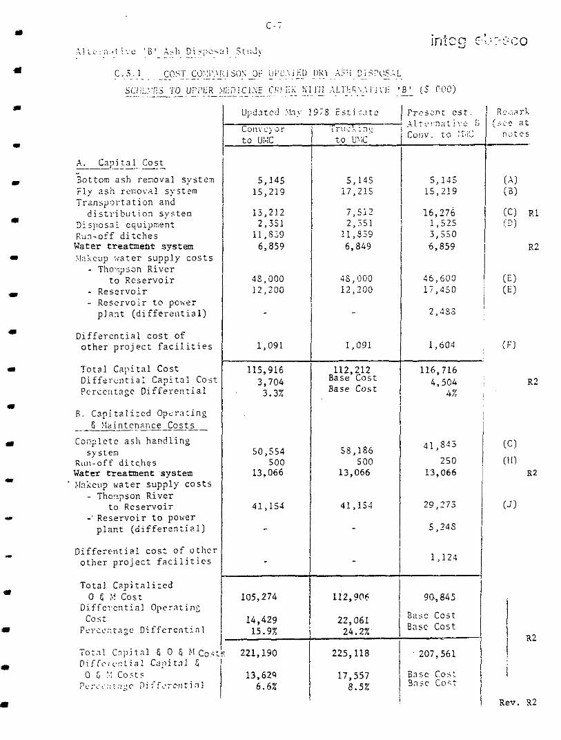
"" . " - -. " A . Capi ta l Cos t
Bottom ash reDoval sys tem
Transpor?a t ion and F l y a s h rrll:ov%I system
d i s t r i b u t i o n s y s t e m D i s p o s a l c q u i p e n t Run-of f d i tches Water treatmehe system :.!;l;ct!p w a t e r s u p p l y c o s t s
- Thor,;?son River t o R e s e r v o i r
- Rese rvo i r - Rese rvo i r t o power
-
p l a n t ( d i f f e r s n t i a l )
D i f f e r e n t i a l c o s t of o t h e r p r o j e c t f a c i l i t i e s
T o t a l C a p i t a l C o s t D i f f a r c n t i a l C a p i t a l C o s t PcrccI I t . ?gc Di f fe ren t ia l
E. Capitalized O p s r a t i n x E Mzintcnmce Cos ts
Coi3;letc a s h h a n d l i n g
Run-off d i t c h e s Water treatment system
' N Z ~ C ~ I ? m t e r s u p p l y c o s t s - Tho::!pson River
t o Rese rvo i r - ' Rese rvo i r t o pOlier
system
p l a n t ( d i f f e r e n t i a l )
D i f f e r e n t i a l c o s t o f u t h c r o t h e r p r o j e c t f a c i l i t i e s
To ta l C2p i t a l i ; ed
Diffc;-c:ltia! Operating
F c ~ ~ s c ~ ~ : a g c D i f f e r e n t i a l
T o t a l C n ; ? i t n l & 0 & $1 Co; : P i F f c : r : 1 t i a i C 2 : ' i t n l G
0 6 M c o s t
c o s t
0 6 Co5t. ~ : F : ~ ~ ~ - : ! : r i ~ l
i.
I I
5,145 15,219
13,212 2,351
11,539 6,859
45,000 12,200
1,091
115,916 3,704 3.3%
50,553 500
13,066
41 ~ 154
-
105,274
14,429 15.9%
221,190
13,629 6.6%
5,115 i 7 , 2 1 5
7,512 2 ,551
11,839 6,849
4s, 1500 1 2 . 2 0 0
1,091
Base Cost Base Cost
112,212
58,lSb 500
13,066
4 1 , IS-!
-
-
112,5106
22,061 24.2%'
225,118
17,557 8.5%
5,115 15,2!9
16 ,276 1 , 5 2 5 3,550 6,859
45 ,603 1 7 , 4 5 0
2,355
1,604
116,716 4,504
4% i
41,S';
2 5 0 13,066
29,273
5,24s
1,124
90,845
32.5: Cost Basc c o s t
207,561
h s c Co5t 3nsc C o c t
Rev. X2

C-8 integ-ebasco
Alternative 'B' Ash Disposal Study
Notes on C.3.1
(A) Updated >lay 1978 cost in C.2 is based on underground B..\. collkcting conveyors. For comparison purposes, Alternative 'B' estimate is based on above ground B.4. collecting conveyors and therefore the same cost is used for all three schemes.
(B) May 1978 schemes use silos ob 2 4 hour capacity. For the updated conveying scheme to UMC 12 hour capacity silos (Same as for Alternative 'B' - see B.5.1.5 in this report) are assumed for comparison of the schemes.
(C) Updated capital cost of conveyor system to UblC does not include future conveyor extension costs which are considered in 0 & M costs. No such extension is required for Alternative ' B ' conveyor arrangement.
(D) Alternative ' B ' assumes that the reclamation of the disposal area would be performed entirely by contractors and therefore less disposal equipment is required.
(E) Makeup water supply system costs for dry ash disposal schemes to UMC assumed same as those for Base Scheme and Alternative 'A' in item 10 of economic analysis (Section 8.4 of this report).
(F) Dry ash disposal schemes to UMC assumed to include the following features from item 2(e) of economic analysis (Section B.4 of this report) : Differential cost of plant site run off holding pond $ 1,017,000 Differential cost of access road 74,000
$ 1,091,000

c-9 integ-ebasco
A l t e r n a t i v e 'B' Ash Disposal Study
( G ) C a p i t a l i z e d 0 & M cos t s fo r t he comple t e a sh hand l ing sys t em i n
updated dry ash d i sposa l schemes to UMC, are taken f rom C . 2 and
made complete by the fol lowing adjustments:
- l abour con ten t i nc reased by s taff of 23 t o g i v e t o t a l s t a f f i n g
requi rement for ash sys tem. A t t h e c a p i t a l i z e d c o s t of $407,000
p e r c a p i t a t h i s amounts t o a n a d d i t i o n o f $9,561 x 10 f o r each
updated scheme.
3
- equipment rep lacement conten t increased to inc lude inp lan t equip-
ment r ep lacemen t a s fo l lows :
Conveying scheme $(5145 + 15219) x 10 x 0.015 x 12.7 = $3879 x 10
Truck Scheme $(514S + 17215) x lo3 x 0.015 x 1 2 . 7 $4260 x 10
3 3
3
(H) 0 & M c o s t s f o r r u n o f f d i t c h e s f o r d r y schemes t o LlMC assumed t o b e
t h e same a s f o r t h e Base Scheme and A l t e rna t ive ' A ' .
(J) Dry ash d i sposa l schemes to UMC assume same e n e r g y c o s t f o r makeu:?
water supply pumping as A l t e r n a t i v e ' A ' (power p lan t water consum?t ion
same as A l t e r n a t i v e ' A ' and no Medicine Creek makeup t o a s h pond is
r e q u i r e d ) .
( K ) D i f f e r e n t i a l 0 & M c o s t s r e l a t i n g t o i tems in Note (F) above , a s smed
n e g l i g i b l e .

integ-ebasco c-10
A l t e r n a t i v e ' E ' Ash Disposal Study
C.3.2 Technical Advantages of Alternat ive 'E' Over Conveying t o UMC
1. Conveyor arrangement of Alternative 'E' i s s impler and permi ts
bottom ash to cover f l y ash on t h e main conveyor t o t h e v a l l e y .
T h i s r e d u c e s d u s t i n g p o t e n t i a l . I t i s no ted , however , t ha t the
conveyor arrangement to UMC, i f adopted, could possibly be
r e v i s e d i n d e t a i l e d e n g i n e e r i n g t o g i v e t h e same advantage.
2 . A l t e r n a t i v e 'B' prov ides t he oppor tun i ty t o d i spose o f ash
t o g e t h e r w i t h mine waste i n Medicine Creek Valley. In such
a case savings may be r e a l i z e d t h r o u g h t h e p o s s i b i l i t y of
obviat ing the need for ash compact ion and the reduct ion of some d is t r ibu t ion and mobi le suppor t ing equipment . I t i s
b e l i e v e d t h a t t h e a d d i t i o n o f a s h c o u l d a l s o p r o v i d e g r e a t e r
s t a b i l i t y t o t h e mine was te s torage . These poss ib i l i t i es a re
n o t a v a i l a b l e w i t h a s h d i s p o s a l i n UMC.
3 . Shou ld ma in tenance o f t he runof f f ac i l i t i e s be necessa ry
a f t e r p l an t decommiss ion ing , A l t e rna t ive . 'B' would be l e s s
c o s t l y due t o t h e r e d u c e d l e n g t h o f d i t c h e s .

c-11 integ-ebasco
C . 3 . 3 Technical Advantages of Alternative ' B ' over Trucking to UhIC
1 . Alternative ' B ' is less labour intensive. Should trucking be performed by BCH staff there could be complications in personnel scheduling of the trucking operation to match ash production urder varying plant load conditions.
2 . Truck movements, particularly at intersections of the truck roads with other roads, may be hazardous and interfere with other prcject operations. Trucking requires a larger maintenance operation and is also more vulnerable to icy road conditions in hilly terrain than conveying.
3. Alternative 'B' also has the advantages 2 and 3 o f Section C.2.3
vhen compared with the trucking operation to UMC.

D - 1
A l t e r n a t i v e ' B ' Ash Disposal Study
integ-ebasco
D .
1.
2 .
3.
4 .
5.
6 .
7.
8 .
9 .
10.
11.
1 2 .
13.
REFERENCES
Personal Communication. B . C . Hydro & Power A u t h o r i t y . L e t t e r
M.A.Favel1 t o E . A . J o d i d i o d a t e d 1 August, 1978. Subject:
Medicine Creek Hydrology and Water Quality.
American Public Health Association, American Water Works A s s o c i a t i o n ,
and Water Pol lut ion Control Federat ion. 1971. Standard Methods €or
the Examinat ion of Water and Wastewater, 13th Edition. .American
Publ ic Heal th Associat ion, Washington, D.C .
Personal Communication. Integ-Ebasco. Memo J.E. B u t t s t o R . D .
Merer dated 13 June, 1977. Subject : Makeup Water Q u a l i t y f o r t h s
Hat Creek Thermal Generating Station.
B . C . Hydro & Power Authority. 1978. Hat Creek Project Master
Schedule. Drawing Number 604H-Z30-X931202.
Minutes of Meeting of 18 August, 1978. B . C . Hydro and Power Auth ' s r i ty
and Integ-Ebasco.
B . C . Hydro and Power Authori ty . Predicted Operat ing Regime, Issuz 1
dated 31 May, 1978.
Minutes of Meeting of 10 Ju ly , 1978. B . C . Hydro and Power Author i ty .
Integ-Ebasco and CMJV.
Integ-Ebasco. Makeup Water Requirement and Reservoir Drawdown.
S ta t ion Des ign Manual Sec t ion 17 .1-a , Revis ion 1, da ted 24 August,
1977. Beak Consul tan ts L t d . 1978. Hydrology, Drainage, Water Qual i ty
and Use Report . Unpublished. Hat Creek Pro jec t Deta i led Envi ron-
menta l S tudies . B . C . Hydro and Power Authori ty , Vancouver , B . C .
Personal Communication. B . C . Hydro and Power Author i ty . S.A. Rimiley
t o J . E . Butts. Telecommunication of 1 September , 1978. Subject :
Medicine Creek Diversion.
Integ-Ebasco. Water Management Study f o r the Proposed Hat Creek
Power Plan. B . C . Hydro and Power Authority, Vancouver, B . C .
February 1978.
Ebasco Services Inc. Water Management Study f o r t h e Lake E r i e
Genera t ing S ta t ion . Niagara Mohawk Power Authori ty . February 1976.
Ebasco Services Inc. Al ternate hlethods of Boi le r Cleaning Waste
Disposal. Houston Lighting and Power Co., Houston, Texas. 1976.

D-2 integ-ebasco
A l t e r n a t i v e ' B ' Ash Disposal Study
1 4 .
15 .
16.
17.
18.
19.
20.
2 1 .
2 2 .
23.
24.
25.
26.
27
28
"Evalua t ion of Ash Disposal Schemes f o r Hat Creek Thermal Plant",
In teg-Ebasco , Ju ly 1977.
"Water Hanagement S t u d y f o r Hat Creek Power Plant" , Integ-Ebasco,
February 1978.
"Summary of Cost Comparison o f Base and Contingent Schemes f o r Ash
Disposal" , Integ-Ebasco, Apri l 1978.
"Report on Visit t o European Power P lan ts to Evalua te Per formance
o f Ash Removal Sys t ems pa r t i cu la r ly t he Cha in Bar Conveyor System
f o r Bottom Ash", I n t e g , November 1977.
" B r i t i s h Columbia Hydro & Power Au thor i ty Hat Creek P ro jec t S t a t ion
Design Manual" and "Supplementary Station Design Manual".
H e l i x l e t t e r t o I n t e g - E b a s c o d a t e d 16 August, 1977 and 19 August,
1977; PlcDowell-Wellman Company l e t t e r t o I n t e g - E b a s c o d a t e d 1 7
March, 1978.
In t eg -Ebasco l e t t e r da t ed 18 Sep tember , 1978 t o ASH.
ASH l e t t e r d a t e d 25 October, 1978.
"Hat Creek Mining Feas ib i l i ty S tudy: Par t 3 -- Mine Planning",
CEIJV, Draft, J u l y , 1 9 7 8 .
"Minutes of the Meet ing , In teg-Ebasco" , 10 Ju ly , 1978.
"Water Supply and Ash Disposal Reservoirs : Prel iminary Design
Report -- Vols. 1 & Z", HEDD, March, 1978.
"Water Supply and Ash Disposal Study" by BCH HEDD Report DD 1 2 2
dated August, 1978. Meeting wi th S.A. Ridley. SeTtember 8 , 1978. Subjec t : Winter -
Summer Ash p i l e d i s p o s a l .
Sandwell Project Memorandum V4251/4 da ted 8 September, 1978.
I n g e r s o l l - R a n d l e t t e r t o I n t e g d a t e d 27 October, 1978.

INTEG-EBASCO
29. "Water Balances" BCH F i l e : 604H-79106 da ted l 4 January 1981.
0-3 Rev. 3 Apr. 1981

.
... -

sc t - I04 6- 0 L C
i
I
1 !
j 1 x .
.I
i


I

"
J
.

/ /

, .
-77”-

* i
,-