harvesting the wind energy - norcowe for web/ss2015-presentasonar... · harvesting the wind energy...
TRANSCRIPT
Harvesting the Wind Energy
Trond Kvamsdal Dept. of Mathematical Sciences
Norwegian University of Science & Technology
Contents
• Introduction • Converting kinetical wind energy to
mechanical energy • HAWT vs VAWT • Converting mechanical energy to electrical
energy • Offshore wind turbines

Introduction
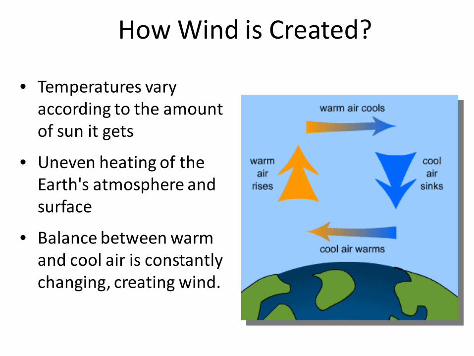
• Temperatures vary according to the amount of sun it gets
• Uneven heating of the Earth's atmosphere and surface
• Balance between warm and cool air is constantly changing, creating wind.
How Wind is Created?
• The terms "wind energy" or "wind power" describe the process by which the wind is used to generate mechanical power or electricity.
• Wind turbine rotors convert the kinetic energy in the wind into mechanical power.
• Wind power is the conversion of wind energy into a useful form of energy, such as using: • wind turbines to make electricity, • wind mills for mechanical power, • wind pumps for water pumping • etc.
Wind Energy
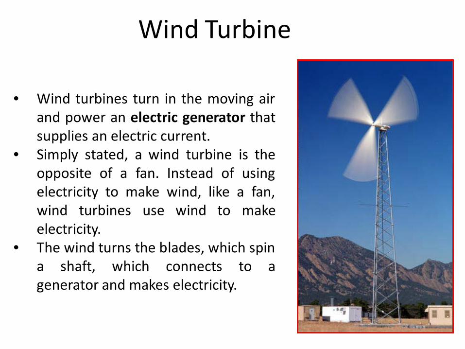
• Wind turbines turn in the moving air
and power an electric generator that supplies an electric current.
• Simply stated, a wind turbine is the opposite of a fan. Instead of using electricity to make wind, like a fan, wind turbines use wind to make electricity.
• The wind turns the blades, which spin a shaft, which connects to a generator and makes electricity.
Wind Turbine
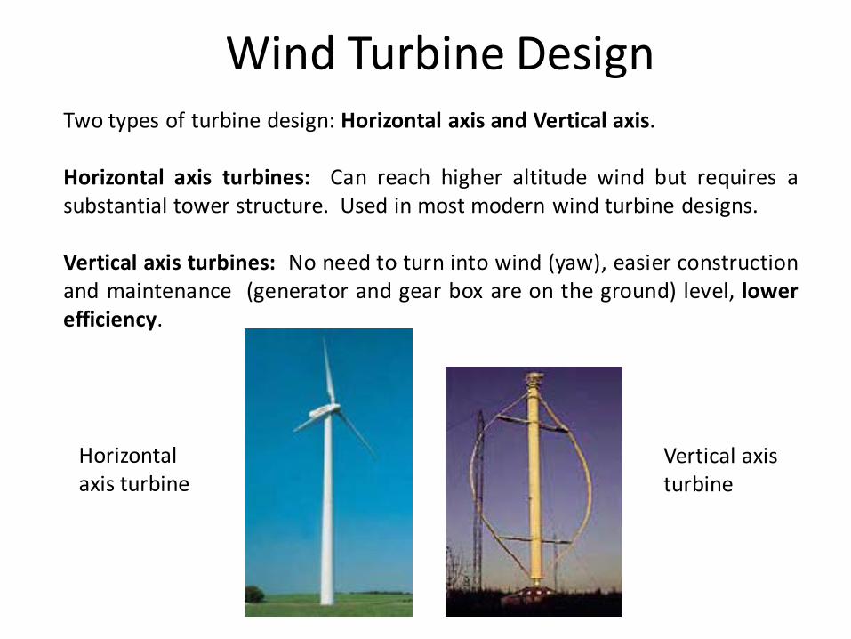
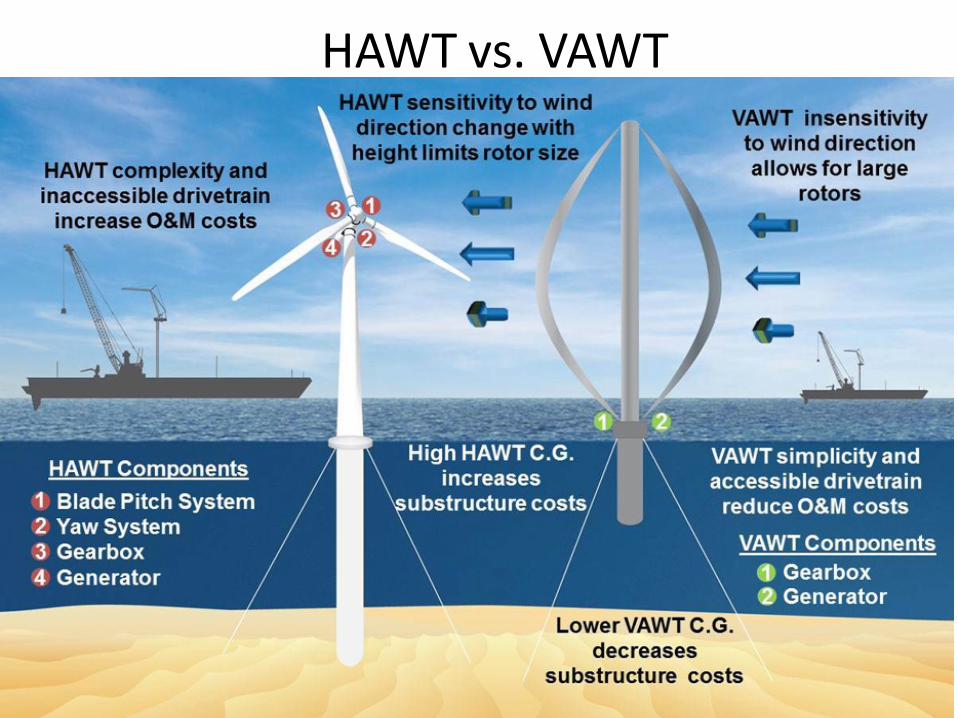
Two types of turbine design: Horizontal axis and Vertical axis. Horizontal axis turbines: Can reach higher altitude wind but requires a substantial tower structure. Used in most modern wind turbine designs. Vertical axis turbines: No need to turn into wind (yaw), easier construction and maintenance (generator and gear box are on the ground) level, lower efficiency.
Vertical axis turbine
Horizontal axis turbine
Wind Turbine Design
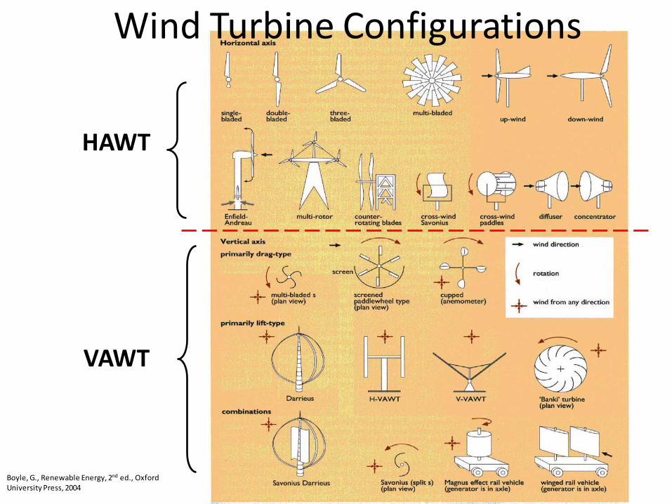
HAWT
VAWT
Boyle, G., Renewable Energy, 2nd ed., Oxford University Press, 2004
Wind Turbine Configurations

Wind Turbine Components
Converting Kinetic Wind Energy to Mechanical Energy
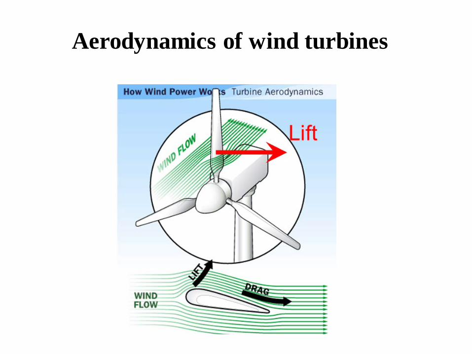
Aerodynamics of wind turbines
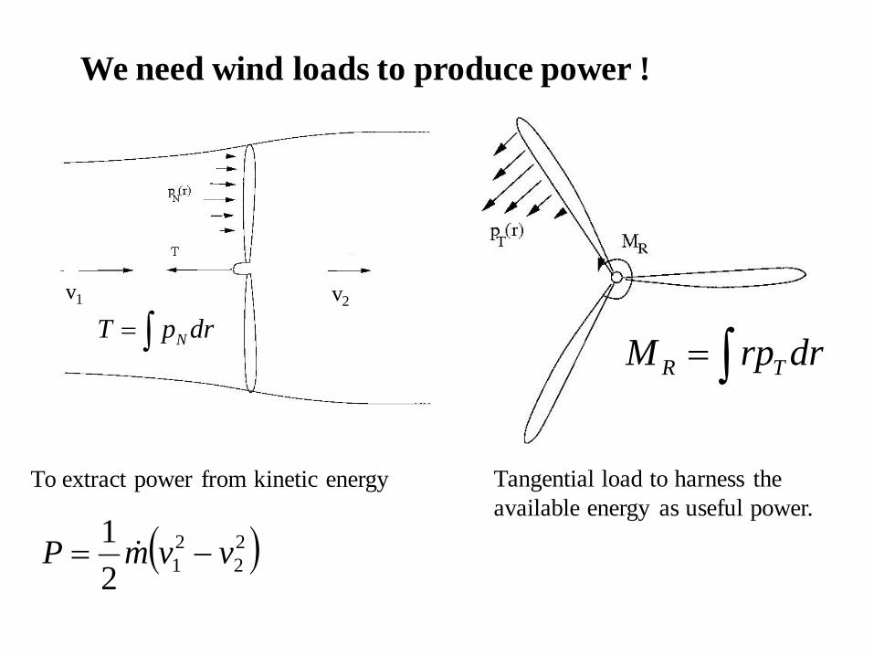
We need wind loads to produce power !
To extract power from kinetic energy
NT p dr= ∫R TM rp dr= ∫
Tangential load to harness the available energy as useful power.
( )22
212
1 vvmP −=
v1 v2
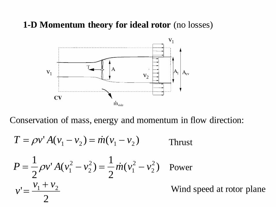
1-D Momentum theory for ideal rotor (no losses)
Conservation of mass, energy and momentum in flow direction:
Thrust
Power
Wind speed at rotor plane
v1 v2
v1
2' 21 vvv +=
)(21)('
21 2
221
22
21 vvmvvAvP −=−= ρ
)()(' 2121 vvmvvAvT −=−= ρ
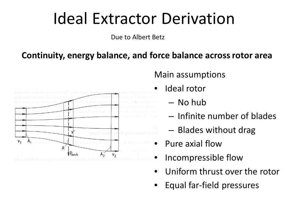
Ideal Extractor Derivation Due to Albert Betz
Continuity, energy balance, and force balance across rotor area
Main assumptions • Ideal rotor
– No hub – Infinite number of blades – Blades without drag
• Pure axial flow • Incompressible flow • Uniform thrust over the rotor • Equal far-field pressures
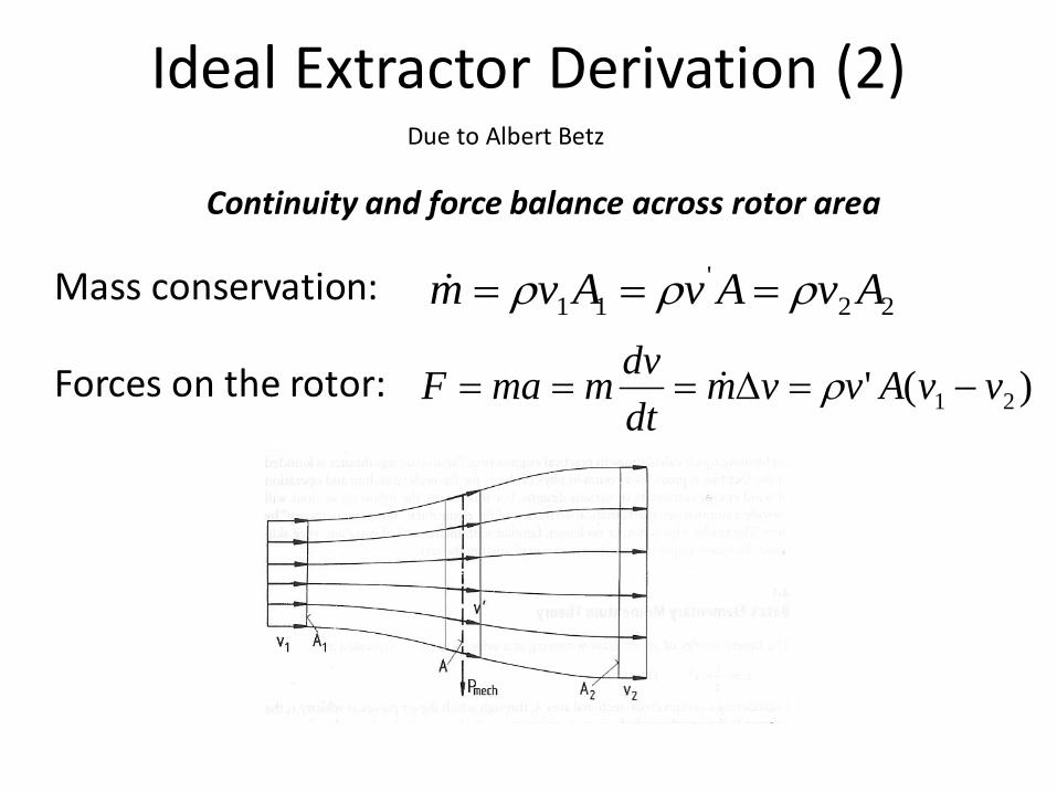
Ideal Extractor Derivation (2)
22'
11 AvAvAvm ρρρ ===
Due to Albert Betz
Continuity and force balance across rotor area
)(' 21 vvAvvmdtdvmmaF −=∆=== ρ
Mass conservation:
Forces on the rotor:
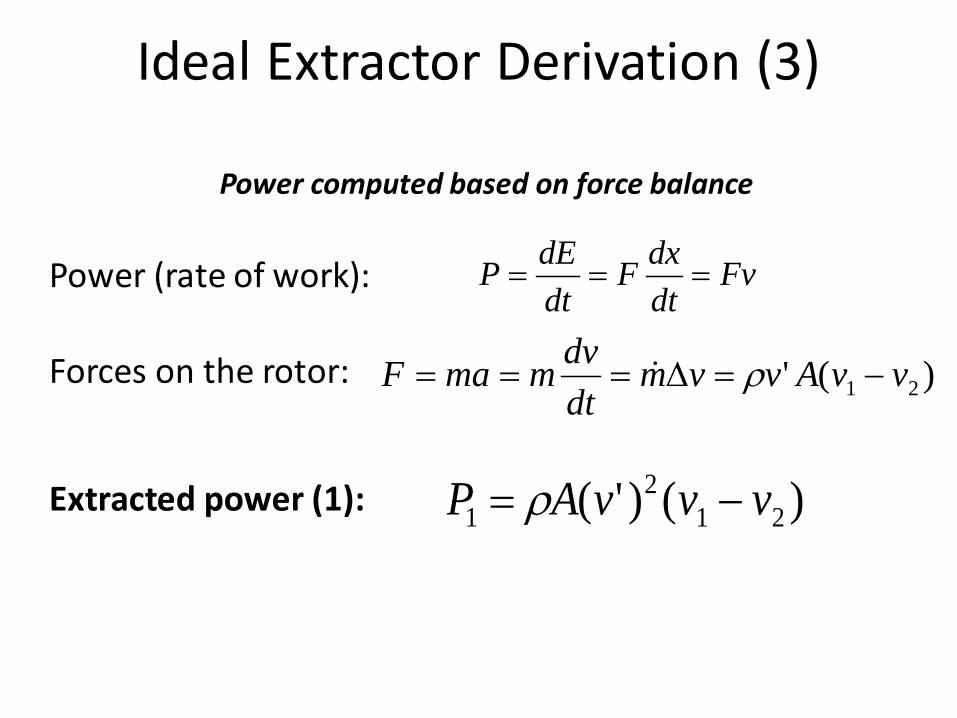
Ideal Extractor Derivation (3)
FvdtdxF
dtdEP ===
Power computed based on force balance
)(' 21 vvAvvmdtdvmmaF −=∆=== ρ
Power (rate of work):
Forces on the rotor:
)()'( 212
1 vvvAP −= ρExtracted power (1):
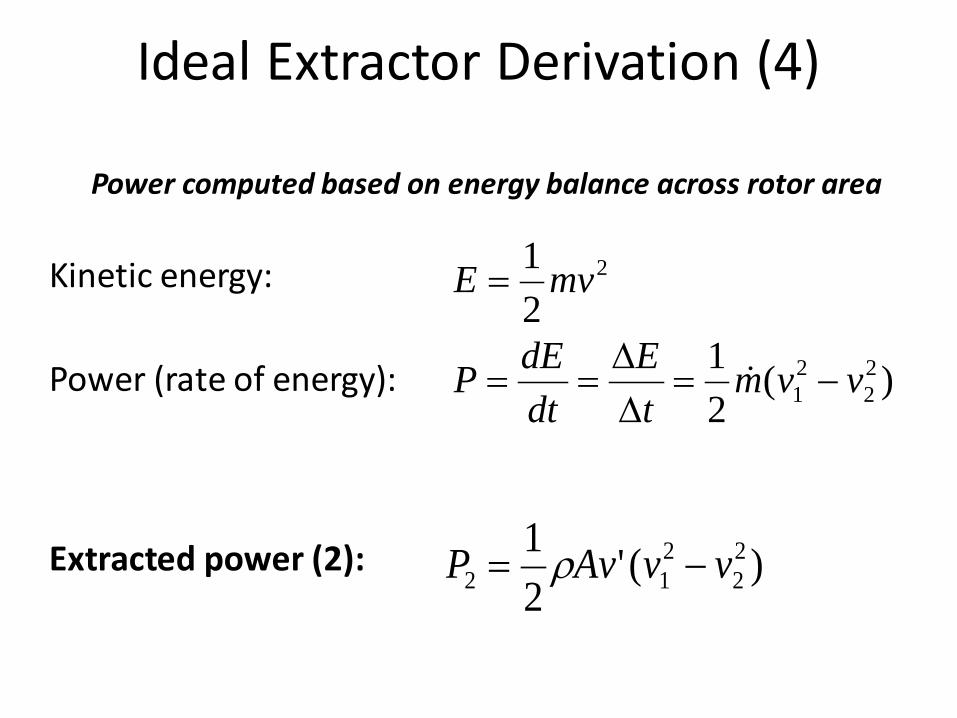
Ideal Extractor Derivation (4)
)(21 2
221 vvm
tE
dtdEP −=
∆∆
==
Power computed based on energy balance across rotor area
Power (rate of energy):
)('21 2
2212 vvAvP −= ρExtracted power (2):
Kinetic energy: 2
21 mvE =
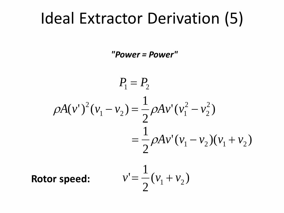
Ideal Extractor Derivation (5)
"Power = Power"
21 PP =
Rotor speed:
)('21)()'( 2
22121
2 vvAvvvvA −=− ρρ
))(('21
2121 vvvvAv +−= ρ
)(21' 21 vvv +=

Ideal Extractor Derivation (6)
221' vvv +
=
AvP 310 2
1 ρ=
( ) )(41 2
22121 vvvvAP −+= ρ
We have found that:
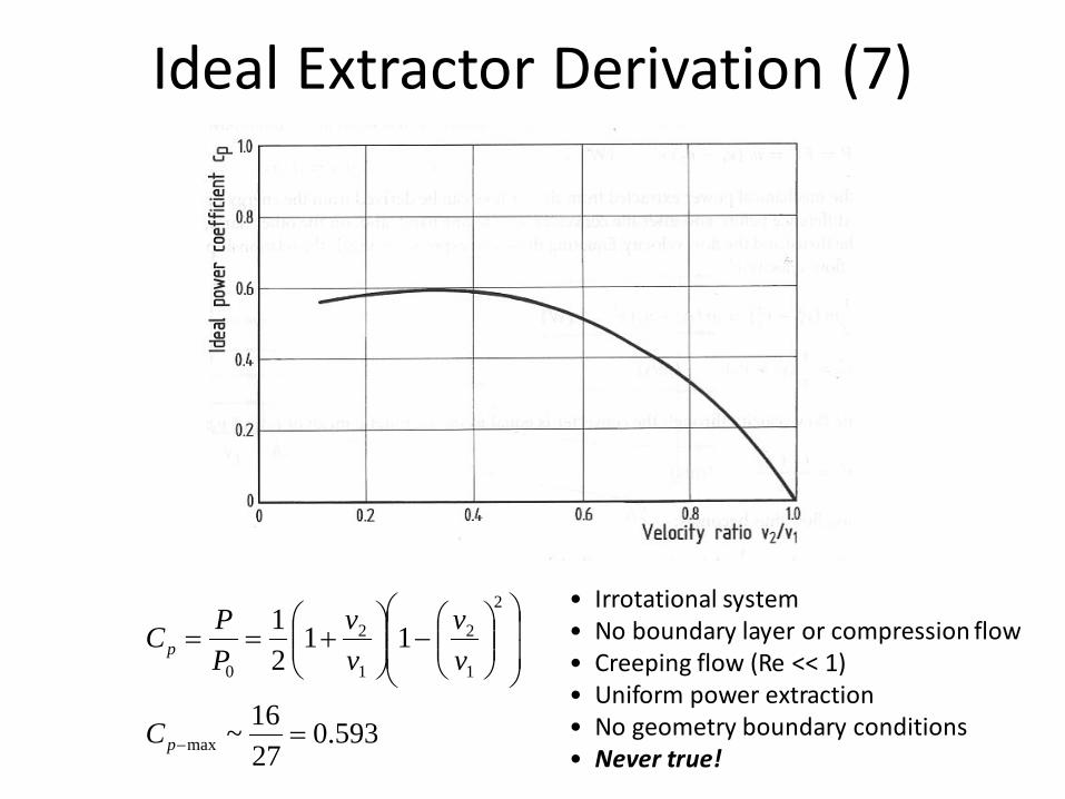
Ideal Extractor Derivation (7)
593.02716~
1121
max
2
1
2
1
2
0
=
−
+==
−p
p
C
vv
vv
PPC
• Irrotational system • No boundary layer or compression flow • Creeping flow (Re << 1) • Uniform power extraction • No geometry boundary conditions • Never true!

More Rigor: Deviation from Betz Limit
1vR
Aωλ ≡
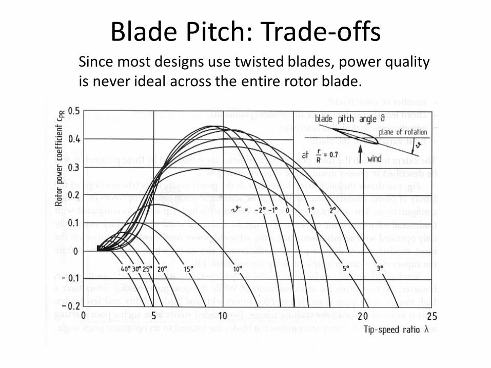
Blade Pitch: Trade-offs Since most designs use twisted blades, power quality is never ideal across the entire rotor blade.
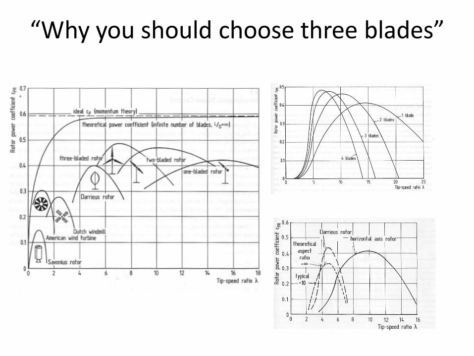
“Why you should choose three blades”
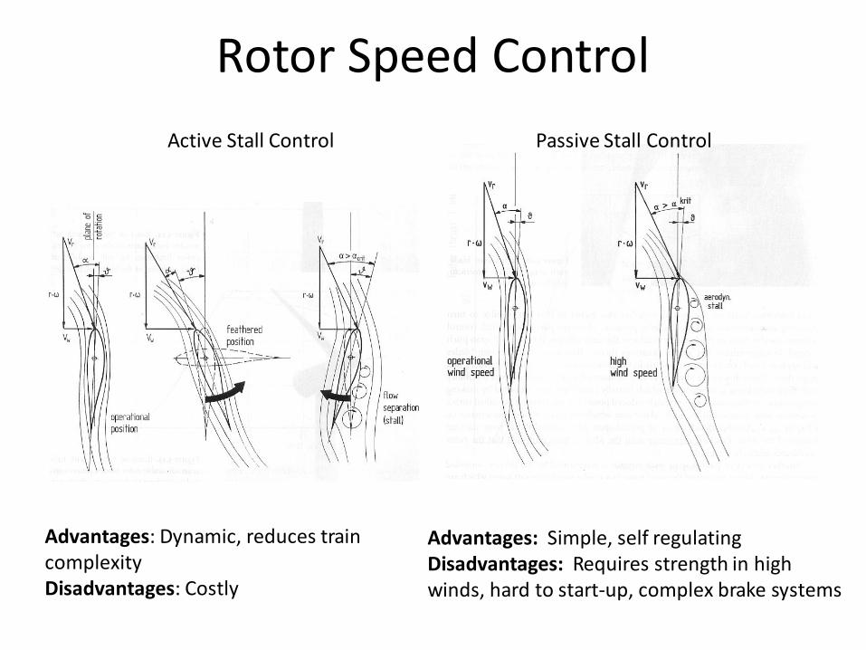
Rotor Speed Control Active Stall Control Passive Stall Control
Advantages: Dynamic, reduces train complexity Disadvantages: Costly
Advantages: Simple, self regulating Disadvantages: Requires strength in high winds, hard to start-up, complex brake systems
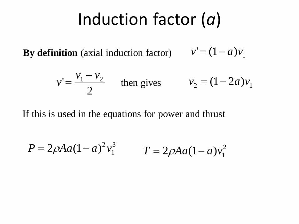
By definition (axial induction factor)
then gives
If this is used in the equations for power and thrust
2' 21 vvv +=
Induction factor (a)
1)1(' vav −=
12 )21( vav −=
31
2)1(2 vaAaP −= ρ 21)1(2 vaAaT −= ρ

312
po
PCV Aρ
=21
2T
o
TCV Aρ
=
Definition of power and thrust coefficients
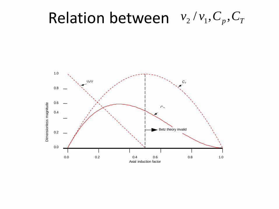
24 (1 )pC a a= − 4 (1 )TC a a= −
,max T16 8 10.59 for C at27 9 3pC a= ≈ = =
Betz limit
Induction factor (a) (continued)
1.0
0.8
0.6 CP
0.4
0.2
0.0
Dim
ensi
onle
ss m
agni
tude
1.0 0.8 0.4 0.6 Axial induction factor
0.2 0.0
U4/U CT
Betz theory invalid
Relation between Tp CCvv ,,/ 12

The wanted loads is created by the lift and drag from the local flow past the blade
cos sinsin cos
N
T
p L Dp L D
φ φφ φ
= += −
L and D depends on • Angle of attack • Airfoil geometry • Reynold number
Loads on a turbine blade
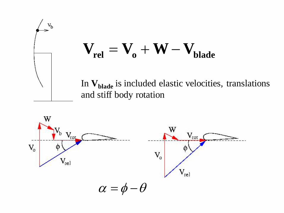
= + −rel o bladeV V W V
In Vblade is included elastic velocities, translations and stiff body rotation
α φ θ= −

Several options, as e.g. ● Full CFD ● Vortex methods (unsteady panel methods, lifting line etc.) ● BEM But since we are solving in the time domain with Δt small a fast model is needed and BEM is almost always used. The more advanced models are mostly used to check the various submodels in the BEM method
Computational methods

BEM Blade Element Moment Method
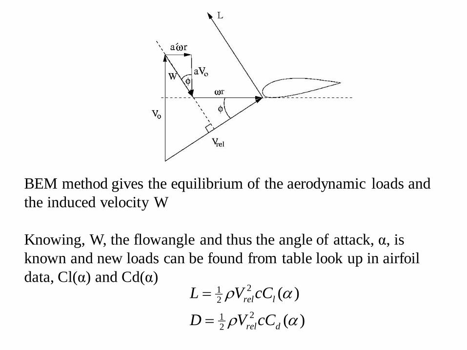
BEM method gives the equilibrium of the aerodynamic loads and the induced velocity W Knowing, W, the flowangle and thus the angle of attack, α, is known and new loads can be found from table look up in airfoil data, Cl(α) and Cd(α)
212
212
( )
( )rel l
rel d
L V cC
D V cC
ρ α
ρ α
=
=
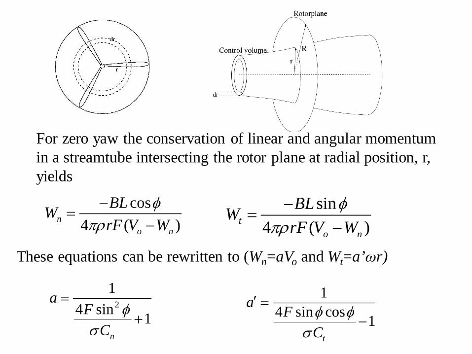
For zero yaw the conservation of linear and angular momentum in a streamtube intersecting the rotor plane at radial position, r, yields
cos4 ( )n
o n
BLWrF V W
φπρ−
=−
sin4 ( )t
o n
BLWrF V W
φπρ−
=−
These equations can be rewritten to (Wn=aVo and Wt=a’ωr)
21
4 sin 1n
aF
Cφ
σ
=+
14 sin cos 1
t
a FCφ φ
σ
′ =−

Prandtl’s tip loss factor In the BEM method we assume no azimuthal variation of W corresponding to infinitely many blades For a finite number of blades the flow is different, especially near the tip, as shown using a simple vortex model with constant circulation and using Biot-Savart
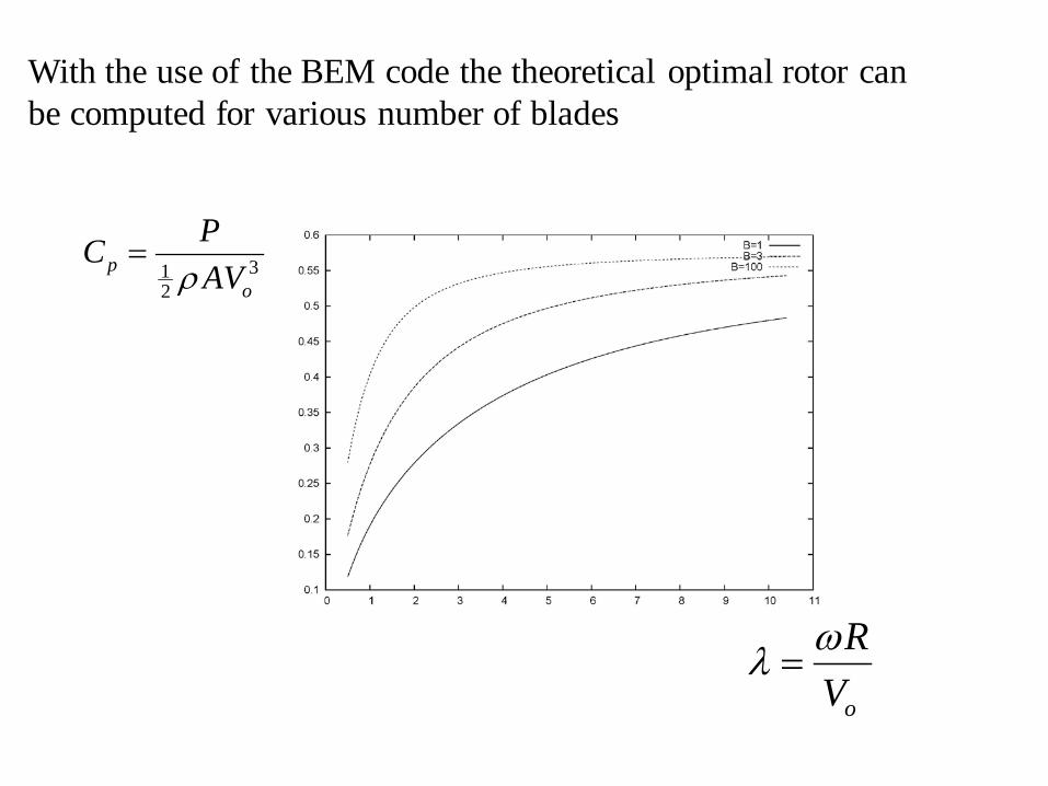
312
po
PCAVρ
=
o
RVωλ =
With the use of the BEM code the theoretical optimal rotor can be computed for various number of blades
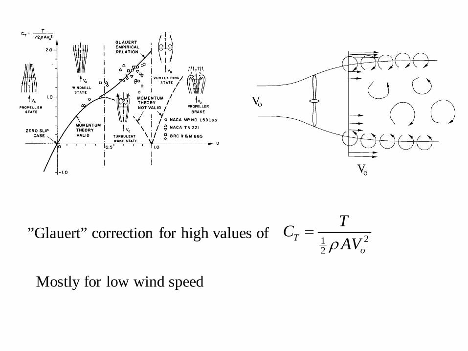
”Glauert” correction for high values of 212
To
TCAVρ
=
Mostly for low wind speed
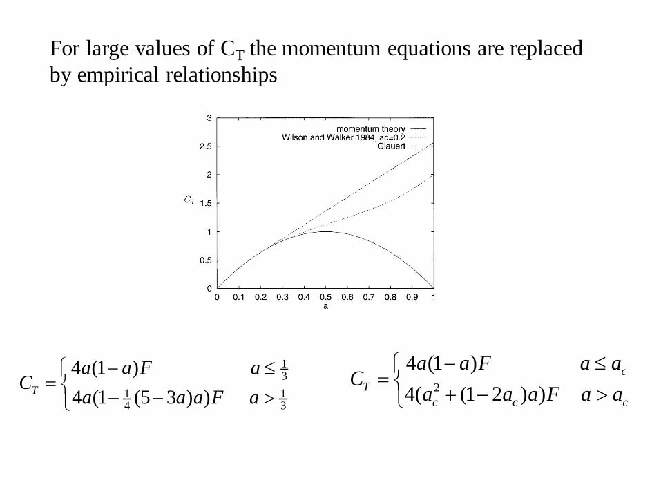
13
1 14 3
4 (1 )4 (1 (5 3 ) )T
a a F aC
a a a F a− ≤
= − − >2
4 (1 )4( (1 2 ) )
cT
c c c
a a F a aC
a a a F a a− ≤
= + − >
For large values of CT the momentum equations are replaced by empirical relationships
HAWT vs VAWT
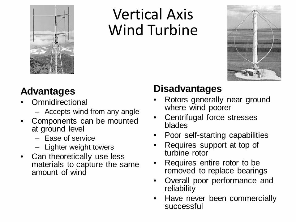
Advantages • Omnidirectional
– Accepts wind from any angle • Components can be mounted
at ground level – Ease of service – Lighter weight towers
• Can theoretically use less materials to capture the same amount of wind
Disadvantages • Rotors generally near ground
where wind poorer • Centrifugal force stresses
blades • Poor self-starting capabilities • Requires support at top of
turbine rotor • Requires entire rotor to be
removed to replace bearings • Overall poor performance and
reliability • Have never been commercially
successful
Vertical Axis Wind Turbine
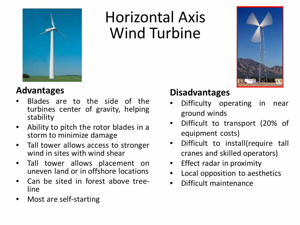
Advantages • Blades are to the side of the
turbines center of gravity, helping stability
• Ability to pitch the rotor blades in a storm to minimize damage
• Tall tower allows access to stronger wind in sites with wind shear
• Tall tower allows placement on uneven land or in offshore locations
• Can be sited in forest above tree-line
• Most are self-starting
Disadvantages • Difficulty operating in near
ground winds • Difficult to transport (20% of
equipment costs) • Difficult to install(require tall
cranes and skilled operators) • Effect radar in proximity • Local opposition to aesthetics • Difficult maintenance
Horizontal Axis Wind Turbine
HAWT vs. VAWT

• Drag designs – Savonius
Type of Wind Turbine Design Wind turbines are designed based on either aerodynamic Drag or Lift force.
• Lift designs – VAWT Darrieus – Most HAWT designs
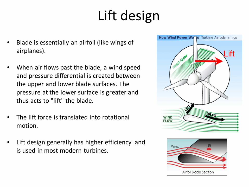
• Blade is essentially an airfoil (like wings of airplanes).
• When air flows past the blade, a wind speed and pressure differential is created between the upper and lower blade surfaces. The pressure at the lower surface is greater and thus acts to "lift" the blade.
• The lift force is translated into rotational motion.
• Lift design generally has higher efficiency and is used in most modern turbines.
Lift
Lift design
Ken Youssefi / Hsu Engineering 10, SJSU 45
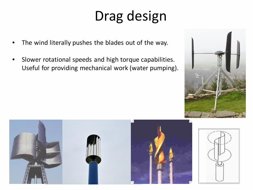
• The wind literally pushes the blades out of the way.
• Slower rotational speeds and high torque capabilities. Useful for providing mechanical work (water pumping).
Drag design

Converting Mechanical Energy to Electrical Energy
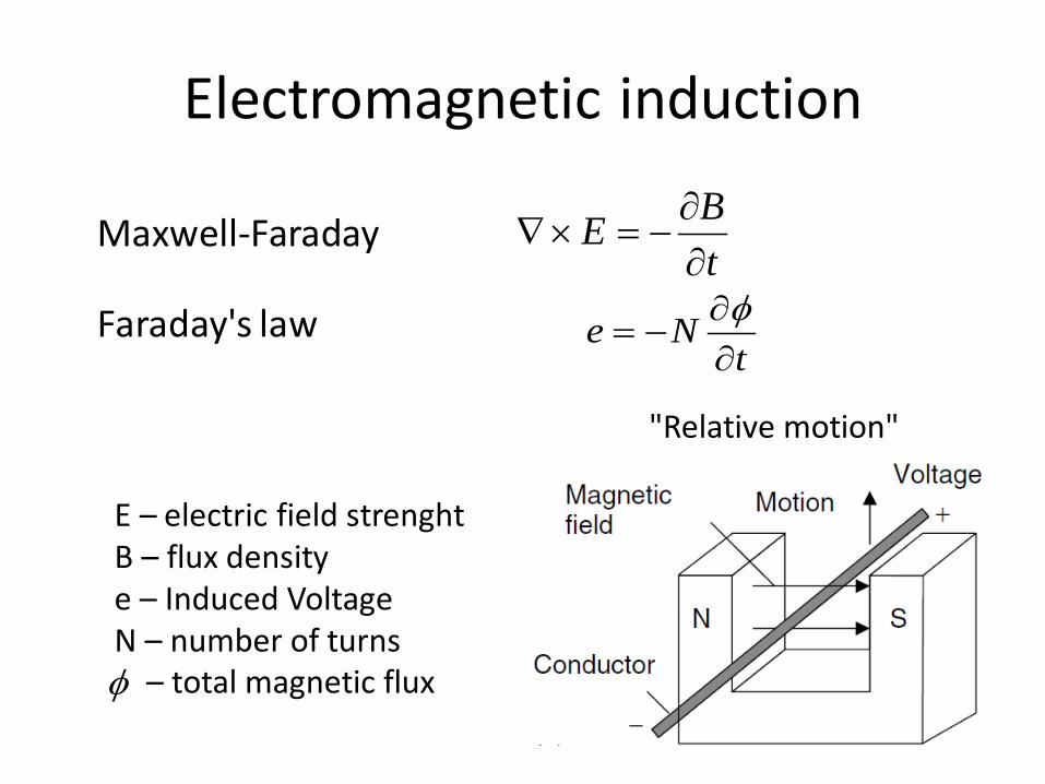
Electromagnetic induction
tNe
∂∂
−=φ
tBE∂∂
−=×∇Maxwell-Faraday
Faraday's law
E – electric field strenght B – flux density e – Induced Voltage N – number of turns φ – total magnetic flux
"Relative motion"
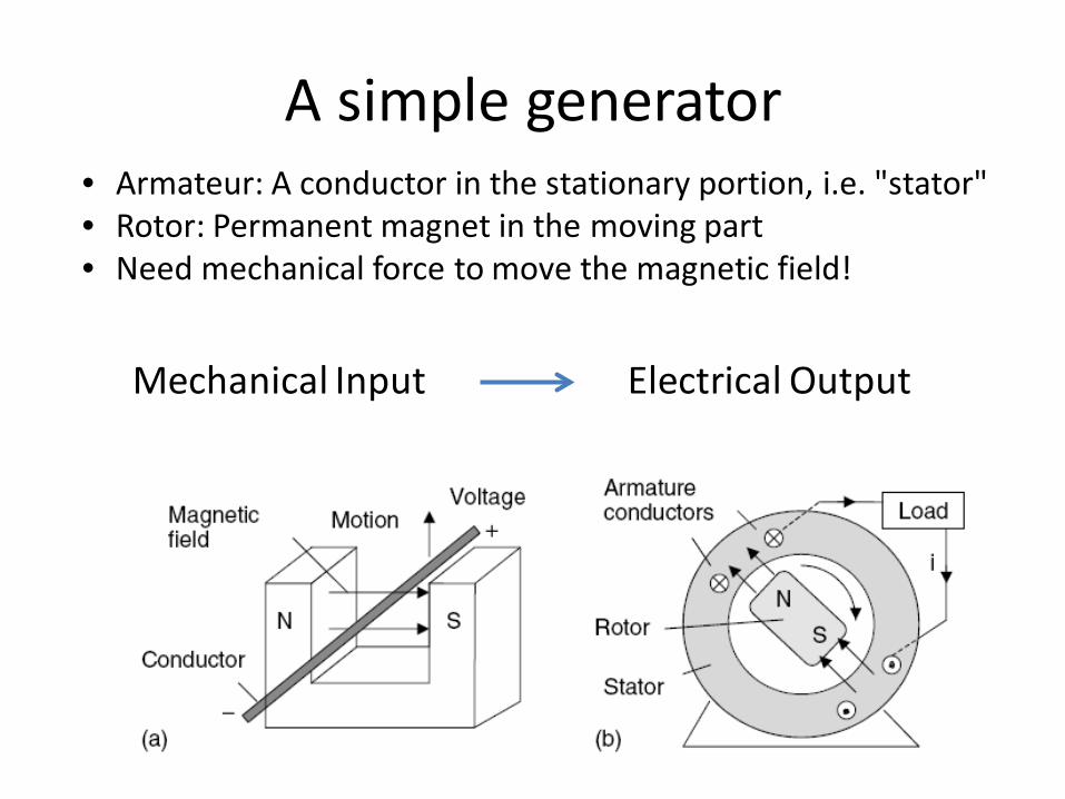
A simple generator • Armateur: A conductor in the stationary portion, i.e. "stator" • Rotor: Permanent magnet in the moving part • Need mechanical force to move the magnetic field!
Mechanical Input Electrical Output
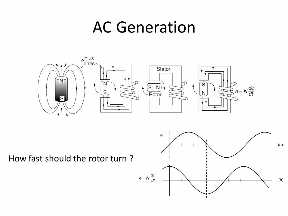
AC Generation
How fast should the rotor turn ?

Rotation rate If we want to generate 60 Hz frequency:
When a rotor has more poles:

How to create magnetic field • Use permanent magnet for small generator • Use DC current passing through a coil

Self induced magnetic field Create rotating magnetic field in stator • Coils imbedded in a 3-phase
generator • Need AC-voltage

Major types of generators
Synchronous generator • Operate at constant rational
speed to create constant voltage
• Need magnetic field • Permanent magnet rotor for
small machine • Almost all WT creates
magnetic field by DC current
Asynchronous generator • Induction generator • Do not operate at fixed
speed • Magnetic field is induced
from AC voltage
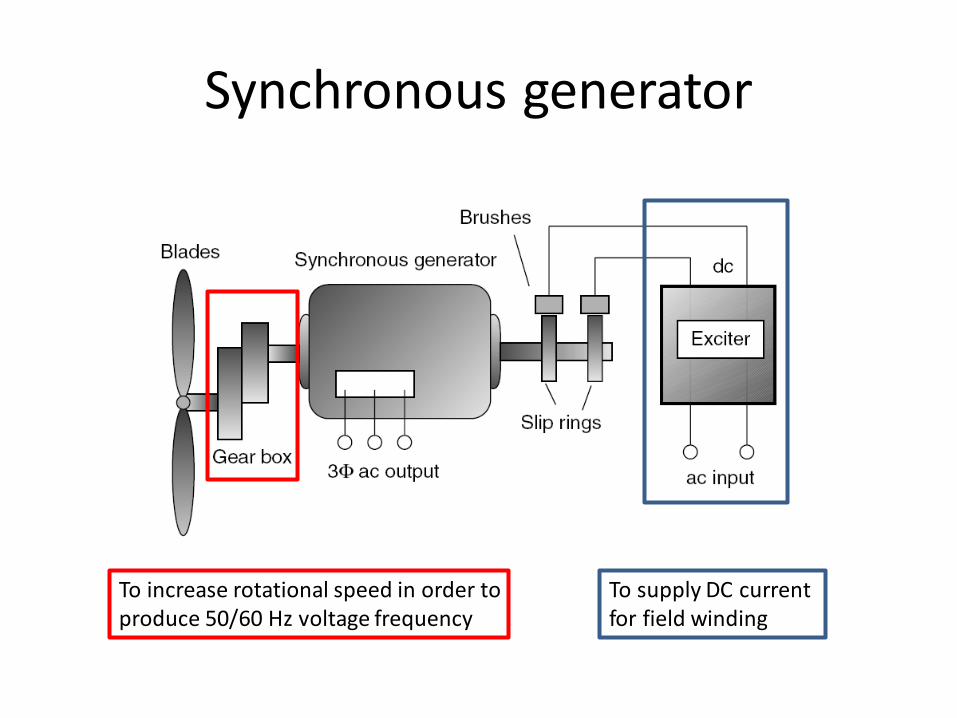
Synchronous generator
To supply DC current for field winding
To increase rotational speed in order to produce 50/60 Hz voltage frequency

Induction machine
• Require rotating magnetic field, supplied by AC voltage
• Use (squirrel) cage rotor made from a number of aluminium bars shorted together at their ends, forming a cage
• Rotor have to spin with a slower speed than sychronous speed
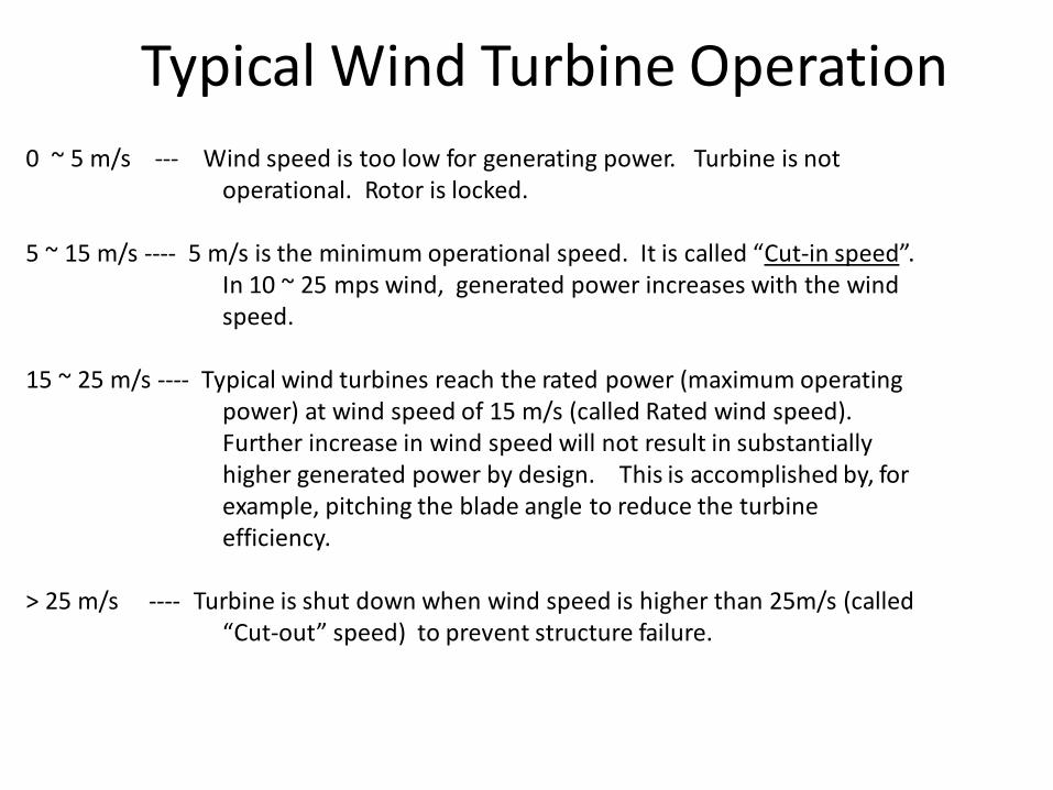
0 ~ 5 m/s --- Wind speed is too low for generating power. Turbine is not operational. Rotor is locked.
5 ~ 15 m/s ---- 5 m/s is the minimum operational speed. It is called “Cut-in speed”.
In 10 ~ 25 mps wind, generated power increases with the wind speed.
15 ~ 25 m/s ---- Typical wind turbines reach the rated power (maximum operating
power) at wind speed of 15 m/s (called Rated wind speed). Further increase in wind speed will not result in substantially higher generated power by design. This is accomplished by, for example, pitching the blade angle to reduce the turbine efficiency.
> 25 m/s ---- Turbine is shut down when wind speed is higher than 25m/s (called
“Cut-out” speed) to prevent structure failure.
Typical Wind Turbine Operation
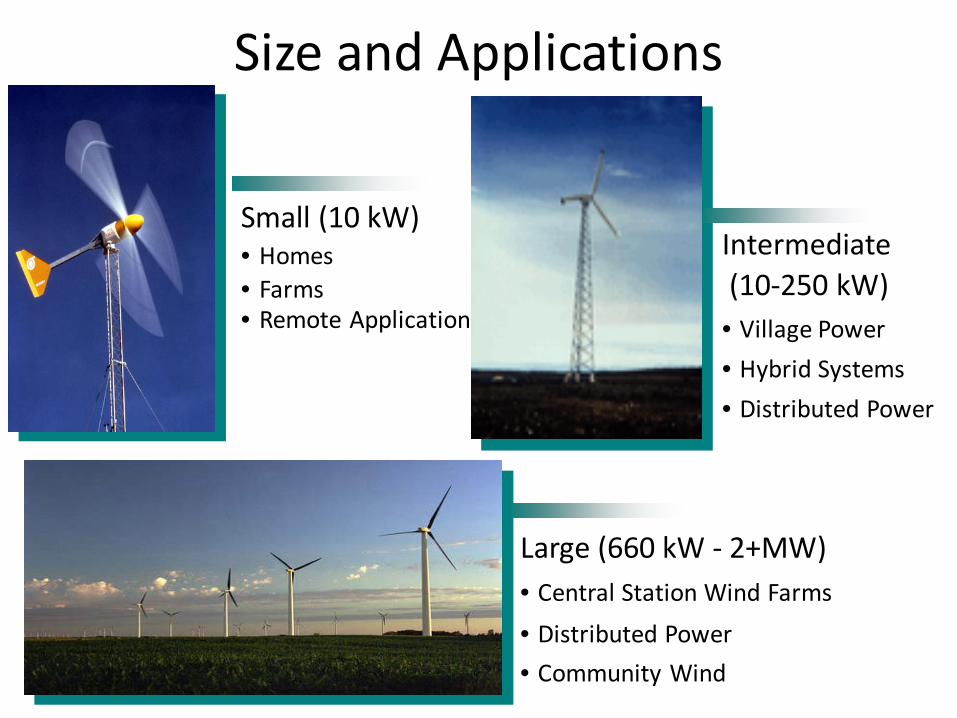
Small (10 kW) • Homes • Farms • Remote Application
Intermediate (10-250 kW) • Village Power • Hybrid Systems • Distributed Power
Large (660 kW - 2+MW) • Central Station Wind Farms • Distributed Power • Community Wind
Size and Applications
Offshore wind turbines

What is an Offshore Wind Turbine? A wind turbine shall be considered as an offshore wind turbine
if the support structure is subject to hydrodynamic loading.

More energy than from the Middle East ! Potential of North Sea
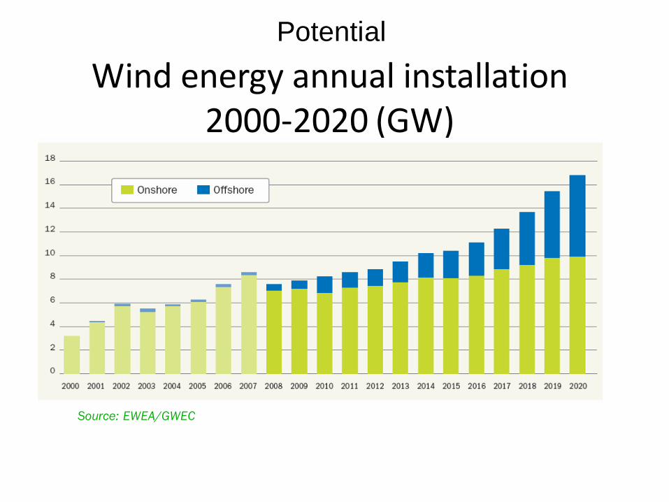
Wind energy annual installation 2000-2020 (GW)
Source: EWEA/GWEC
Potential

Bottom Fixed Offshore Wind Turbine
• Includes: – Rotor/nacelle
assembly (RNA) – Support
structure • Tower • Substructure • Foundation
s u b - s t r u c t u r e
p i l e
f o u n d a t i o n
p i l e
p l a t f o r m
t o w e r t o w e r
s u b - s t r u c t u r e
sea floor
s u p p o r t s t r u c t u r e
rotor-nacelle assembly
seabed
water level

Floating Offshore Wind Turbine
• Includes: – Rotor/nacelle
assembly (RNA) – Support
structure • Tower • Floating
substructure • Mooring
system

Foundations Design with Changing Depth

Common Types of Fixed Bottom Support Structures

Common Types of Fixed Bottom Support Structures
• Monopiles • Tripods • Jackets • Gravity based
http://www.theengineer.co.uk/in-depth/the-big-story/wind-energy-gets-serial/1012449.article

• Wind turbines and foundation structures • Underwater high voltage cables • Offshore substations and operations
• Onshore substations • Onshore high voltage transmission
Equipment Needed: Onshore to Offshore
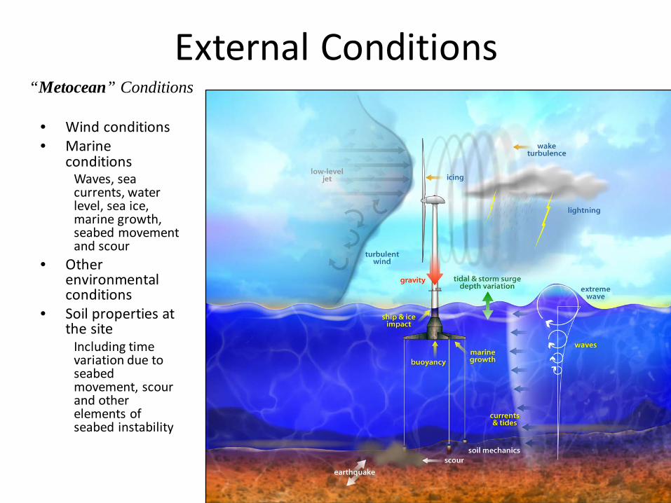
External Conditions
• Wind conditions • Marine
conditions Waves, sea currents, water level, sea ice, marine growth, seabed movement and scour
• Other environmental conditions
• Soil properties at the site
Including time variation due to seabed movement, scour and other elements of seabed instability
“Metocean” Conditions

Assessment of Metocean External Conditions for Offshore Wind Turbines
• Wind speeds and directions • Significant wave heights, wave periods and directions • Correlation of wind and wave statistics • Current speeds and directions • Water levels • Occurrence and properties of sea ice • Occurrence of icing • Other parameters: air, water temperatures, densities;
water salinity; bathymetry, marine growth, etc
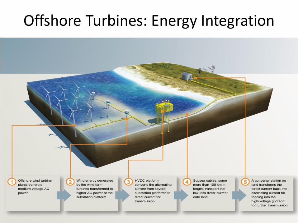
Offshore Turbines: Energy Integration

Things to Consider While Designing Offshore Wind Turbines
• Wave models • Hurricanes/cyclones • Wind shear as affected by waves • Floating ice • Boat (service vessel) impact • Soil characterization • Vortex induced vibrations
Active Area of Research in Offshore Technology Development
• Aerodynamic design-FSI (blades/structure) • Foundation design (soil/structure interaction) • Material properties • Offshore data collection • Environmental impact

Technology Trend for Wind Turbines
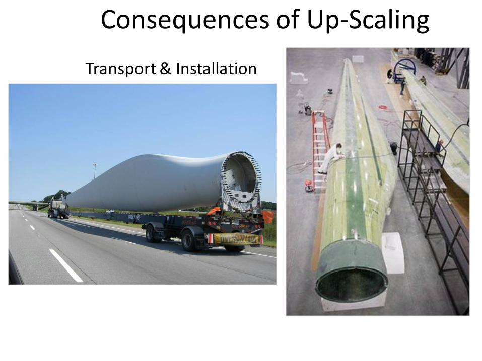
Transport & Installation
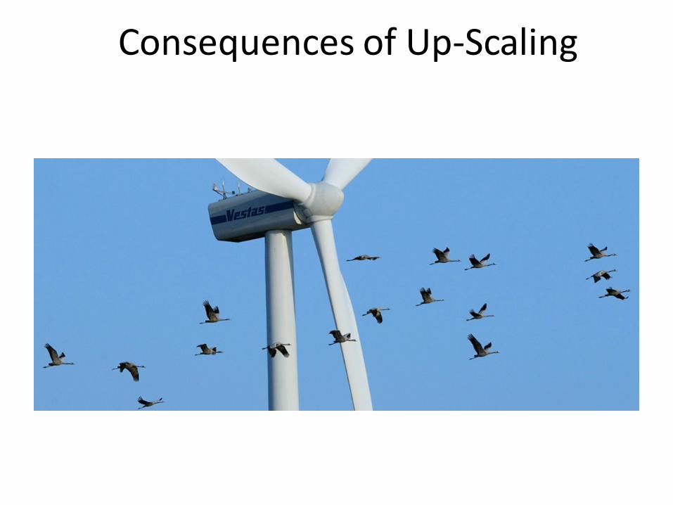
Consequences of Up-Scaling
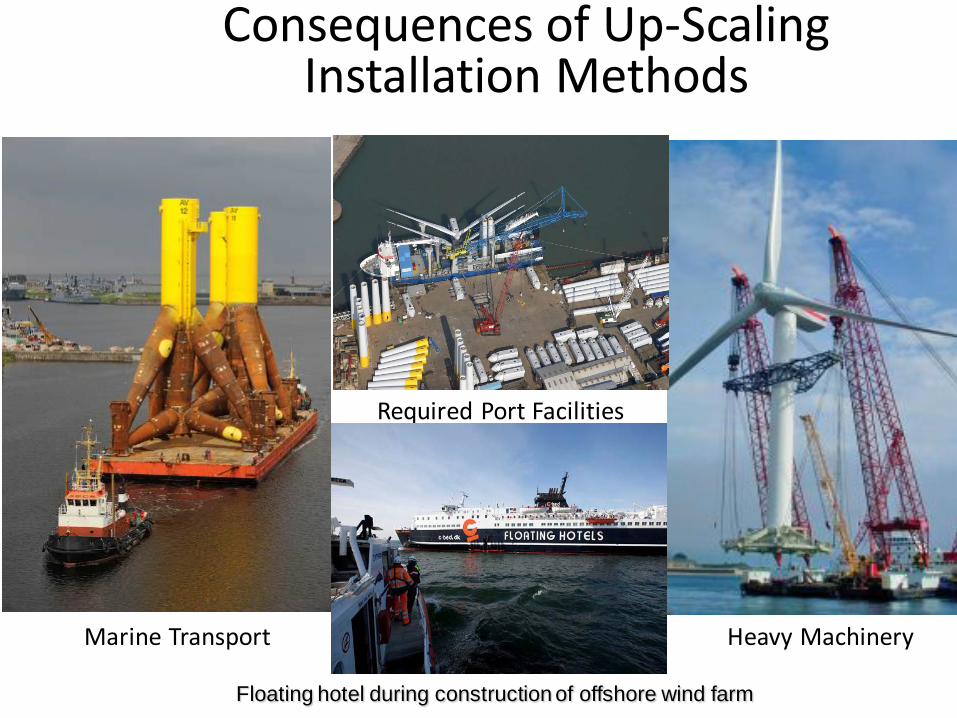
Marine Transport
Required Port Facilities
Floating hotel during construction of offshore wind farm
Consequences of Up-Scaling Installation Methods
Heavy Machinery
Consequences of Up-Scaling

Consequences of Upscaling
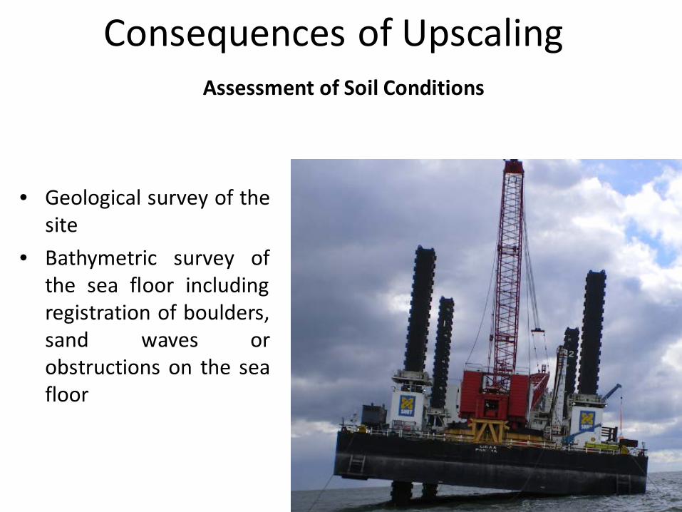
Assessment of Soil Conditions
• Geological survey of the site
• Bathymetric survey of the sea floor including registration of boulders, sand waves or obstructions on the sea floor
Consequences of Upscaling
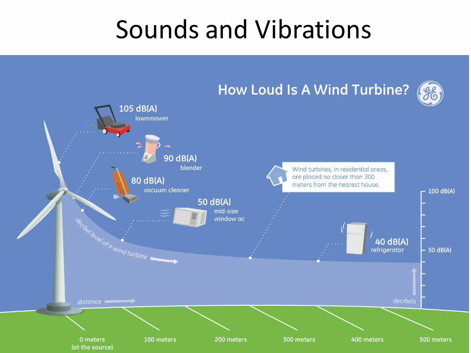
Sounds and Vibrations