hartzell propeller inc. one propeller place piqua, ohio...
TRANSCRIPT

MANUAL REVISION TRANSMITTAL
MANUAL 127 (61-16-27)Metal Spinner Assembly Maintenance Manual
REVISION 6 dated February 2014
Attached is a copy of Revision 6 to Hartzell Manual 127 Page Control Chart for Revision 6:
Remove Insert Chapter/Page No. Chapter/Page No.
COVER COVER Cover/Inside Cover Cover/Inside Cover
REVISION HIGHLIGHTS REVISION HIGHLIGHTS pages 1 thru 4 pages 1 thru 4
SERVICE DOCUMENT LIST SERVICE DOCUMENT LIST pages 1 and 2 pages 1 and 2
LIST OF EFFECTIVE PAGES LIST OF EFFECTIVE PAGES pages 1 and 2 pages 1 and 2
INTRODUCTION INTRODUCTION pages 9 and 10 pages 9 and 10
CHECK CHECK pages 5-1 and 5-2 pages 5-1 and 5-2 pages 5-9 thru 5-14 pages 5-9 thru 5-14 pages 5-14.1 and 5-14.2 insert after page 5-14 pages 5-15 and 5-16 pages 5-15 and 5-16 pages 5-19 and 5-20 pages 5-19 and 5-20 TR-012 Refer to NOTE 1 pages 5-21 thru 5-24 pages 5-21 thru 5-24 page 5-45 and 5-46 page 5-45 and 5-46
REPAIR AND MODIFICATION REPAIR AND MODIFICATION pages 6-1 thru 6-6 pages 6-1 thru 6-6 pages 6-67 and 6-68 pages 6-67 and 6-68
ILLUSTRATED PARTS LIST ILLUSTRATED PARTS LIST pages 10.3-47 and 10.3-48 pages 10.3-47 and 10.3-48 TR-016 Refer to NOTE 1 pages 10.4-10.1 and 10.4-10.2 insert after page 10.4-10
HARTZELL PROPELLER INC.One Propeller PlacePiqua, Ohio 45356-2634 U.S.A.Telephone: 937.778.4200Fax: 937.778.4391
Page 1 of 2

Page Control Chart for Revision 6, continued
Remove Insert Chapter/Page No. Chapter/Page No.
ILLUSTRATED PARTS LIST, CONTINUED ILLUSTRATED PARTS LIST, CONTINUEDpages 10.4-19 thru 10.4-22 pages 10.4-19 thru 10.4-22 TR-015 Refer to NOTE 1 pages 10.5-9 and 10.5-10 pages 10.5-9 and 10.5-10 TR-014 Refer to NOTE 1
NOTE 1: The Record of Revisions page has been revised to include the removal of the Temporary Revision.
NOTE 2: When the manual revision has been inserted in the manual, record the information required on the Record of Revisions page in this manual.
NOTE 3: Pages distributed in this revision may include pages from previous revisions if they are on the opposite side of revised pages. This is done as a convenience to those users who wish to print a two-sided copy of the new revision.
Page 2 of 2

Hartzell Propeller Inc.One Propeller PlacePiqua, Ohio 45356-2634 U.S.A.Phone: 937.778.4200Fax: 937.778.4391
Manual No. 12761-16-27Revision 6February 2014
Metal SpinnerMaintenance Manual

61-16-27 Inside CoverRev. 6 Feb/14
METAL SPINNER MAINTENANCE MANUAL 127
(This page is intentionally blank.)
© 1974, 2003, 2004, 2010, 2011, 2013, 2014 - Hartzell Propeller Inc. - All rights reserved
METAL SPINNER MAINTENANCE MANUAL127
REVISION HIGHLIGHTSPage 1
Rev. 6 Feb/1461-16-27
REVISION HIGHLIGHTSRevision 6, dated February 2014, incorporates the following:• COVER • Revisedtomatchthemanualrevision
• REVISION HIGHLIGHTS • Revisedtomatchthemanualrevision
• SERVICEDOCUMENTLIST • Revisedtomatchthemanualrevision
• LISTOFEFFECTIVEPAGES • Revisedtomatchthemanualrevision• CHECK • RevisedtheinspectioncriteriaforthedomeinTable5-1 • IncorporatedTR-012thatrevisedTable5-1forthebulkhead • Madeotherminorlanguageandformatchanges REPAIRANDMODIFICATION • Revisedthesection“RepairofaDent” • Revisedthesection“FactoryPolish” • CorrectedtheCMnumberforCM160 • Madeotherminorlanguageandformatchanges• ILLUSTRATEDPARTSLIST • IncorporatedTR-016thataddednewspinnerassemblypartnumber105298() • Added3-bladedspinnermodel104781() • AddedthepartslistsforspinnermodelsD-630-10andD-630-11 • IncorporatedHC-SL-61-331thatintroducedaB-3845-9screwforspinnerdome
attachment • IncorporatedTR-015thataddednewspinnerassemblypartnumber104553() • IncorporatedTR-014thataddednewspinnerassemblypartnumbers104236(),
104552(),and105180()

METAL SPINNER MAINTENANCE MANUAL127
Page 2Rev. 6 Feb/1461-16-27REVISION HIGHLIGHTS
(Thispageisintentionallyblank.)

METAL SPINNER MAINTENANCE MANUAL127
REVISION HIGHLIGHTSPage3
Rev. 6 Feb/1461-16-27
1. Introduction
A. General
(1) Thisisalistofcurrentrevisionsthathavebeenissuedagainstthismanual.PleasecomparetoRECORDOFREVISIONSpagetoensurethatallrevisionshavebeenaddedtothemanual.
B. Components
(1) RevisionNo.indicatestherevisionsincorporatedinthismanual.
(2) IssueDateisthedateoftherevision.
(3) Commentsindicatestheleveloftherevision.
(a) NewIssueisanewmanualdistribution.Themanualisdistributedinitsentirety.Alloftherevisiondatesarethesameandnochangebarsareused.
(b) Reissueisarevisiontoanexistingmanualthatincludesmajorcontentand/ormajorformatchanges.Themanualisdistributedinitsentirety.Alloftherevisiondatesarethesameandnochangebarsareused.
(c) MajorRevisionisarevisiontoanexistingmanualthatincludesmajorcontentorminorformatchangesoveralargeportionofthemanual.Themanualisdistributedinitsentirety.Alloftherevisiondatesarethesame,but change bars are used to indicate the changes incorporated in the latestrevisionofthemanual.
(d) MinorRevisionisarevisiontoanexistingmanualthatincludesminorcontentchangestothemanual.Onlytherevisedpagesofthemanualaredistributed. Each page retains the date and the change bars associated with the last revision to that page.
Revision No. IssueDate Comments
Original Jun/74 NewIssue Revision1 Jan/03 Reissue Revision2 Feb/04 MinorRevision Revision3 May/10 MajorRevision Revision4 Apr/11 MinorRevision Revision5 Feb/13 MinorRevision Revision6 Feb/14 MinorRevision

METAL SPINNER MAINTENANCE MANUAL127
Page 4Rev. 6 Feb/1461-16-27REVISION HIGHLIGHTS
(Thispageisintentionallyblank.)

SERVICE DOCUMENT LIST
SERVICE DOCUMENT LIST
METAL SPINNER MAINTENANCE MANUAL127
Page 1Rev. 6 Feb/1461-16-27
Service Document Number
IncorporationRev./Date
Service Bulletins:SB 119 Rev. 1, Jan/03SB 157 Rev. 1, Jan/03HC-SB-61-230 Rev. 1, Jan/03HC-SB-61-311, R2 Rev. 4, Apr/11
Service Letters:SL 102 Rev. 3, May/10SL 109 Rev. 1, Jan/03SL 117 Rev. 1, Jan/03SL 119 Rev. 1, Jan/03SL 123A Rev. 1, Jan/03HC-SL-61-164 Rev. 1, Jan/03HC-SL-61-166 Rev. 1, Jan/03HC-SL-61-171 Rev. 3, May/10HC-SL-61-179 Rev. 1, Jan/03HC-SL-61-183 Rev. 1, Jan/03HC-SL-61-190 Rev. 1, Jan/03HC-SL-61-199 Rev. 1, Jan/03HC-SL-61-225, R1 Rev. 3, May/10HC-SL-61-230 Rev. 3, May/10HC-SL-61-262 Rev. 3, May/10HC-SL-30-276, R2 Rev. 4, Apr/11HC-SL-61-331 Rev. 6, Feb/14
Service Document Number
IncorporationRev./Date

SERVICE DOCUMENT LIST
SERVICE DOCUMENT LIST
METAL SPINNER MAINTENANCE MANUAL127
Page 2Rev. 6 Feb/1461-16-27
Service Document Number
IncorporationRev./Date
Service Document Number
IncorporationRev./Date

LIST OF EFFECTIVE PAGES
METAL SPINNER MAINTENANCE MANUAL127
Page 1Rev. 6 Feb/1461-16-27
LIST OF EFFECTIVE PAGES
Chapter Page Revision Level Date
Cover/Cover Back Cover/Inside Cover Rev. 6 Feb/14Revision Highlights 1 thru 4 Rev. 6 Feb/14Record of Revisions 1 and 2 Rev. 3 May/10Record of Temporary Revisions 1 and 2 Rev. 5 Feb/13Service Document List 1 and 2 Rev. 6 Feb/14Airworthiness Limitations 1 and 2 Rev. 4 Apr/11List of Effective Pages 1 and 2 Rev. 6 Feb/14Table of Contents 1 and 2 Rev. 3 May/10Introduction 1 thru 4 Rev. 4 Apr/11Introduction 5 and 6 Rev. 3 May/10Introduction 7 and 8 Rev. 4 Apr/11Introduction 9 Rev. 6 Feb/14Introduction 10 Rev. 3 May/10Description and Operation 1 thru 10 Rev. 3 May/10Testing and Fault Isolation 1-1 thru 1-4 Rev. 3 May/10Automatic Test Requirements 2-1 and 2-2 Rev. 3 May/10Disassembly 3-1 thru 3-4 Rev. 3 May/10Cleaning 4-1 thru 4-4 Rev. 3 May/10Check 5-1 Rev. 3 May/10Check 5-2 Rev. 6 Feb/14Check 5-3 thru 5-9 Rev. 3 May/10Check 5-10 thru 5-13 Rev. 6 Feb/14Check 5-14 Rev. 3 May/10Check 5-14.1 and 5-14.2 Rev. 6 Feb/14Check 5-15 Rev. 6 Feb/14Check 5-16 thru 5-19 Rev. 3 May/10Check 5-20 and 5-21 Rev. 6 Feb/14Check 5-22 Rev. 3 May/10Check 5-23 Rev. 6 Feb/14Check 5-24 thru 5-44 Rev. 3 May/10Check 5-45 and 5-46 Rev. 6 Feb/14Check 5-47 and 5-48 Rev. 3 May/10Repair and Modification 6-1 Rev. 6 Feb/14

LIST OF EFFECTIVE PAGES
METAL SPINNER MAINTENANCE MANUAL127
Page 2Rev. 6 Feb/1461-16-27
LIST OF EFFECTIVE PAGES
Chapter Page Revision Level Date
Repair and Modification 6-2 Rev. 4 Apr/11Repair and Modification 6-3 thru 6-5 Rev. 6 Feb/14Repair and Modification 6-6 thru 6-26 Rev. 3 May/10Repair and Modification 6-27 Rev. 4 Apr/11Repair and Modification 6-28 thru 6-59 Rev. 3 May/10Repair and Modification 6-60 thru 6-66 Rev. 4 Apr/11Repair and Modification 6-67 thru 6-68 Rev. 6 Feb/14Assembly 7-1 thru 7-4 Rev. 3 May/10Fits and Clearances 8-1 thru 8-12 Rev. 3 May/10Special Tools, Fixtures, and Equipment 9-1 thru 9-4 Rev. 3 May/10Illustrated Parts List 10.1-1 thru 10.1-8 Rev. 3 May/10Illustrated Parts List 10.2-1 thru 10.2-18 Rev. 3 May/10Illustrated Parts List 10.2-19 Rev. 5 Feb/13Illustrated Parts List 10.2-20 thru 10.2-23 Rev. 3 May/10Illustrated Parts List 10.2-24 Rev. 4 Apr/11Illustrated Parts List 10.2-25 and 10.2-26 Rev. 3 May/10Illustrated Parts List 10.2-27 and 10.2-28 Rev. 5 Feb/13Illustrated Parts List 10.3-1 thru 10.3-6 Rev. 3 May/10Illustrated Parts List 10.3-7 and 10.3-8 Rev. 4 Apr/11Illustrated Parts List 10.3-9 Rev. 5 Feb/13Illustrated Parts List 10.3-10 thru 10.3-21 Rev. 3 May/10Illustrated Parts List 10.3-22 and 10.3-23 Rev. 4 Apr/11Illustrated Parts List 10.3-24 thru 10.3-45 Rev. 3 May/10Illustrated Parts List 10.3-46 thru 10.3-47 Rev. 5 Feb/13Illustrated Parts List 10.3-48 Rev. 6 Feb/14Illustrated Parts List 10.4-1 thru 10.4-10 Rev. 3 May/10Illustrated Parts List 10.4-10.1 and 10.4-10.2 Rev. 6 Feb/14Illustrated Parts List 10.4-11 thru 10.4-18 Rev. 3 May/10Illustrated Parts List 10.4-19 thru 10.4-22 Rev. 6 Feb/14Illustrated Parts List 10.5-1 thru 10.5-9 Rev. 3 May/10Illustrated Parts List 10.5-10 Rev. 6 Feb/14Illustrated Parts List 10.6-1 thru 10.6-14 Rev. 3 May/10

METAL SPINNER MAINTENANCE MANUAL127
INTRODUCTION Page 9Rev. 6 Feb/1461-16-27
6. Definitions
Term Definition
Annealed ........................... softening of material caused by overexposure to heat
Brinelling ........................... a depression caused by failure of the material in compression
Corrosion........................... gradual wearing away or deterioration caused by chemical action
Crack ................................. physical separation of two adjoining portions of metal caused by excessive stress, cuts, nicks, scratches, or corrosion at that point.
Dent .................................. isthepermanentdeflectionofthecrosssectionthatisvisibleon both sides with no visible change in cross sectional thickness
Depression ........................ surface area where the material has been compressed but not removed
Distortion ........................... alteration of the original shape or size of a component
Erosion .............................. gradual wearing away or deterioration caused by action of the elements
Exposure ........................... leaving material open to action of the elements
Fretting .............................. erosion of surface material that develops when relative motion of small amplitude takes place between close fitting parts, wearing away the surface
Gouge ............................... surface area where material has been removed
Impact Damage ................. damage that occurs when the propeller blade or hub assembly strikes, or is struck by, an object while in flight or on the ground
Nick .................................. a sharp, notch-like displacement of material
Overhaul............................ the periodic disassembly, inspection, repair, refinish, and reassembly of a propeller assembly
Pitting ................................ formation of a number of small, irregularly shaped cavities in surface material caused by corrosion or wear
Scratch .............................. a thin, shallow cut caused by the movement of a sharp object across a surface

METAL SPINNER MAINTENANCE MANUAL127
INTRODUCTIONPage 10
Rev. 3 May/1061-16-27
7. Abbreviations
Abbreviation Term
AD ................................Airworthiness Directives
AN ................................Army-Navy
AOG .............................Aircraft On Ground
ATA ...............................Air Transport Association
FAA ..............................Federal Aviation Administration
Ft-Lb ............................Foot-Pound
ICA ...............................Instructions for Continued Airworthiness
ID .................................Inside Diameter
In-Lb .............................Inch-Pound
IPL ................................Illustrated Parts List
Lbs ...............................Pounds
MIL-X-XXX ...................Military Specification
MS ...............................Military Standard
OD ...............................Outside Diameter
NAS .............................National Aircraft Standards
N•m ..............................Newton-Meter
PSI ...............................Pounds per Square Inch
RPM .............................Revolutions per Minute
SAE ..............................Society of Automotive Engineers
STC ..............................Supplemental Type Certificate
TBO .............................Time Between Overhaul
TC ................................Type Certificate
TSN ..............................Time Since New
TSO .............................Time Since Overhaul

METAL SPINNER MAINTENANCE MANUAL127
CHECKPage 5-1
Rev. 3 May/1061-16-27
CHECK- CONTENTS
1. Inspection Interval Requirements .......................................................................5-3
2. Mandatory Inspections........................................................................................5-3
A. Inspection of the C-3533( ) Spinner ..............................................................5-3
3. Inspection Requirements ....................................................................................5-4
4. Replacement Requirements ...............................................................................5-4
5. Repair .................................................................................................................5-4
6. Special Inspections .............................................................................................5-5
A. Inspection of the D-4810 Spinner Assembly Spinner Dome .........................5-5
7. SpecificChecks ..................................................................................................5-7
A. DOME (Item 20) ............................................................................................5-9
B. FORWARD BULKHEAD (Item 30) ..............................................................5-17
C. BULKHEAD (Item 50)..................................................................................5-21
D. ADAPTER RING UNIT (Item 70) .................................................................5-25
E. FILLER PLATE (Item 90) .............................................................................5-29
F. DOME CAP (Item 150) ................................................................................5-33
G. SPACER (Item 220) ....................................................................................5-37
H. THREADED MAGNETIC TARGET (Item 270) ............................................5-39
I. SPINNER MOUNTING PLATE (Item 300) ..................................................5-41
J. BULKHEAD SPACER (Item 310) ................................................................5-45

METAL SPINNER MAINTENANCE MANUAL127
Page 5-2Rev. 6 Feb/1461-16-27CHECK
LIST OF FIGURES
Inspecting the D-4810 Spinner Assembly Spinner Dome ...............Figure 5-1 .............5-6
Spinner Dome..................................................................................Figure 5-2 .............5-8
Mounting Screw Hole ......................................................................Figure 5-3 ...........5-12
Spinner Safety Screw and Nutplate.................................................Figure 5-4 ...........5-14
ForwardBulkhead ...........................................................................Figure 5-5 ...........5-16
SpinnerBulkhead ............................................................................Figure 5-6 ...........5-20
C-3409,C-3409-1andC-3030-4SpinnerBulkheads .....................Figure 5-7 ...........5-22
Adapter Ring Unit ...........................................................................Figure 5-8 ...........5-24
Spinner Filler Plate .........................................................................Figure 5-9 ...........5-28
Spinner Cap.....................................................................................Figure 5-10 .........5-32
LIST OF TABLES
Return to Service Criteria ................................................................Table 5-1 ..............5-9
METAL SPINNER MAINTENANCE MANUAL127
CHECKPage 5-9
Rev. 3 May/1061-16-27
Inspect Serviceable Limits Corrective Action
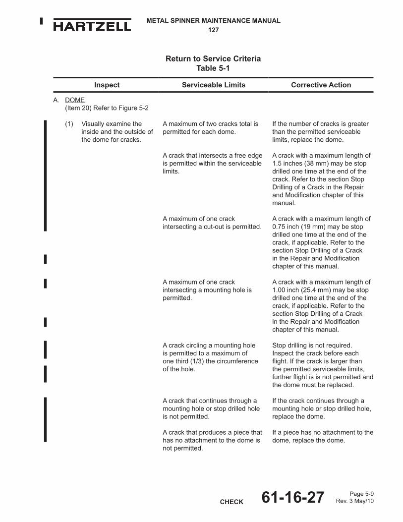
Return to Service CriteriaTable 5-1
Amaximumoftwocrackstotalispermitted for each dome.
Acrackthatintersectsafreeedgeis permitted within the serviceable limits.
Amaximumofonecrackintersecting a cut-out is permitted.
Amaximumofonecrackintersecting a mounting hole is permitted.
Acrackcirclingamountinghole is permitted to a maximum of one third (1/3) the circumference of the hole.
Acrackthatcontinuesthroughamounting hole or stop drilled hole is not permitted.
Acrackthatproducesapiecethathas no attachment to the dome is not permitted.
Ifthenumberofcracksisgreaterthan the permitted serviceable limits, replace the dome.
Acrackwithamaximumlengthof1.5 inches (38 mm) may be stop drilled one time at the end of the crack.RefertothesectionStopDrillingofaCrackintheRepairandModificationchapterofthismanual.
Acrackwithamaximumlengthof0.75 inch (19 mm) may be stop drilled one time at the end of the crack,ifapplicable.RefertothesectionStopDrillingofaCrackintheRepairandModificationchapter of this manual.
Acrackwithamaximumlengthof1.00 inch (25.4 mm) may be stop drilled one time at the end of the crack,ifapplicable.RefertothesectionStopDrillingofaCrackintheRepairandModificationchapter of this manual.
Stop drilling is not required. Inspectthecrackbeforeeachflight.Ifthecrackislargerthanthe permitted serviceable limits, furtherflightisisnotpermittedandthe dome must be replaced.
Ifthecrackcontinuesthroughamounting hole or stop drilled hole, replace the dome.
If a piece has no attachment to the dome, replace the dome.
A. DOME(Item 20) Refer to Figure 5-2
(1) Visually examine the inside and the outside of thedomeforcracks.

METAL SPINNER MAINTENANCE MANUAL127
Page 5-10Rev. 6 Feb/1461-16-27CHECK
(This page is intentionally blank.)

METAL SPINNER MAINTENANCE MANUAL127
CHECKPage 5-11
Rev. 6 Feb/1461-16-27
Component Inspection Criteria Table 5-1
Inspect Serviceable Limits Corrective ActionA. DOME, CONTINUED
(ITEM 20)
(2) Visually examine the dome for wear.
The maximum permitted depth of wear is 0.005 inch (0.12 mm).
Wear that is deeper than 0.005 Inch (0.12 mm) must be removed by polishing with emery cloth or equivalent to a maximum depth of 0.008 Inch (0.20 mm). The maximum permitted total accumulation of any repairs on the dome is 5% of the dome surface area. If the wear is greater than the permitted serviceable limits or corrective action limits replace the dome.
(3) Visually examine the dome for dents. (Refer to the definition of "dent" in the Introduction chapter of this manual.)
The maximum permitted deflectionfromnormalcontouris 0.005 inch (0.12 mm) over a maximum area of one square inch (645 sq. mm) for each dent. The maximum permitted dome surface area that may be dented is 5%. A dent is not permitted toaffectthefitorfunctionofthedome.
If a dent or dents are greater than the permitted serviceable limits, replace or repair the dome in accordance with the section "Repair of Dents" in the Repair and Modificationchapterofthismanual.
(4) Visually examine the dome for scratches.
There may be an unlimited number of scratches that have a maximum permitted depth of material loss of 0.004 inch (0.10 mm).
A scratch that is deeper than 0.004 inch (0.10 mm) must be removed by polishing with emery cloth or equivalent to a maximum depth of 0.008 inch (0.20 mm). The maximum permitted total accumulation of any repairs on the dome is 5% of the dome surface area. If the scratch is greater than the permitted serviceable limits or corrective action limits replace the dome.

METAL SPINNER MAINTENANCE MANUAL127
Page 5-12Rev. 6 Feb/1461-16-27CHECK
W10524
Mounting Screw Hole Figure 5-3
Head of the Mounting Screw
Worn Mounting Screw Hole
Wear beyond the head of the screw is not permitted. At installation, two thirds of the head of the screw must contact the dome.
Example of a Worn Mounting Hole that is NOT PERMITTED(the hole does not extend beyond the head of the screw,
but 2/3 of the head of the screw does not contact the dome)
Example of a Worn Mounting Hole that IS PERMITTED(the hole does not extend beyond the head of the screw
and at least 2/3 of the head of the screw contact the dome)
Example of a Worn Mounting Hole that is NOT PERMITTED(2/3 of the head of the screw contacts the dome,
but the hole extends beyond the head of the screw)
Head of the Mounting Screw
Worn Mounting Screw Hole
Head of the Mounting Screw
Worn Mounting Screw Hole

METAL SPINNER MAINTENANCE MANUAL127
CHECKPage 5-13
Rev. 6 Feb/1461-16-27
Component Inspection Criteria Table 5-1
Inspect Serviceable Limits Corrective ActionA. DOME, CONTINUED
(ITEM 20)
(5) Visually examine the dome for gouges.
The maximum permitted depth of a gouge is 0.004 inch (0.10 mm).
A gouge that is deeper than 0.004 inch (0.10 mm) must be removed by polishing with emery cloth or equivalent to a maximum depth of 0.008 inch (0.20 mm). The maximum total accumulation of any repairs on the dome is 5% of the dome surface area. If the depth of the gouge is greater than the permitted serviceable limits or corrective action limits replace the dome.
(6) Visually examine each mounting hole for wear. Refer to Figure 5-3.
Wear beyond the head of the screw is not permitted. At installation, a minimum of two thirds (2/3) of the head of the screw must contact the dome. A minimum of 3 holes for the dome (one hole between each blade cut-out) cannot be greater than a maximum diameter of 0.205 inch (5.20 mm).
If the wear is greater than the permitted serviceable limits, replace the dome.
(7) Visually examine the dome for corrosion and pitting.
Corrosion is not permitted. The maximum permitted depth of pitting is 0.004 inch (0.10 mm). The maximum permitted total accumulated area of pitting is 2 sq inches (1290 sq mm).
Corrosion is removeable by polishing with emery cloth or equivalent to a maximum depth of 0.008 inch (0.20 mm). The maximum permitted total accumulation of any repairs on the dome is 5% of the dome surface area. Pitting that is deeper than 0.004 inch (0.10 mm) or greater than 2 sq. inches (1290 sq. mm) must be removed by polishing with emery cloth or equivalent to a maximum depth of 0.008 inch (0.20 mm). The maximum permitted total accumulation of any repairs on the dome is 5% of the dome surface area. If the corrosion or pitting is greater than the permitted serviceable limits or corrective action limits replace the dome.

METAL SPINNER MAINTENANCE MANUAL127
Page 5-14Rev. 3 May/1061-16-27CHECK
Dome With Cap Removed
Spinner Safety Screw and Nutplate Figure 5-4
W10500
Cap Safety Screw Fixed Nutplate

METAL SPINNER MAINTENANCE MANUAL127
CHECKPage 5-14.1
Rev. 6 Feb/1461-16-27
Component Inspection Criteria Table 5-1
Inspect Serviceable Limits Corrective ActionA. DOME, CONTINUED
(ITEM 20)
(8) Visually examine each nutplate for missing or damaged threads.
Threads must withstand the screw installation torque satisfactorily.
If the threads will not withstand the screw installation torque satisfactorily, replace the nutplate. Refer to the section Replacement of Nutplates, Rivets, and Rivnuts intheRepairandModificationchapter of this manual.
(9) Visually examine each nutplate for loose attachment hardware.
Loose attachment hardware is not permitted.
If the attachment hardware is loose, replace the nutplate and/or the attachment hardware. Refer to the section Replacement of Nutplates, Rivets, and Rivnuts in the RepairandModificationchapterof this manual.
(10) For a two-piece dome, visually examine the cap safety screw fixed nutplate for damage. Refer to Figure 5-4.
The screw must be present. Loose nutplate attachment hardware is not permitted.
If the screw is not present, replace the screw. If the nutplate is loose, replace the nutplate. The nutplate/screw position may be relocated as necessary. Refer to the section Replacement of Nutplates, Rivets, and Rivnuts in the Repair andModificationchapterofthismanual.
Inspect Serviceable Limits Corrective Action
Return to Service CriteriaTable 5-1
METAL SPINNER MAINTENANCE MANUAL127
Page 5-14.2Rev. 6 Feb/1461-16-27CHECK
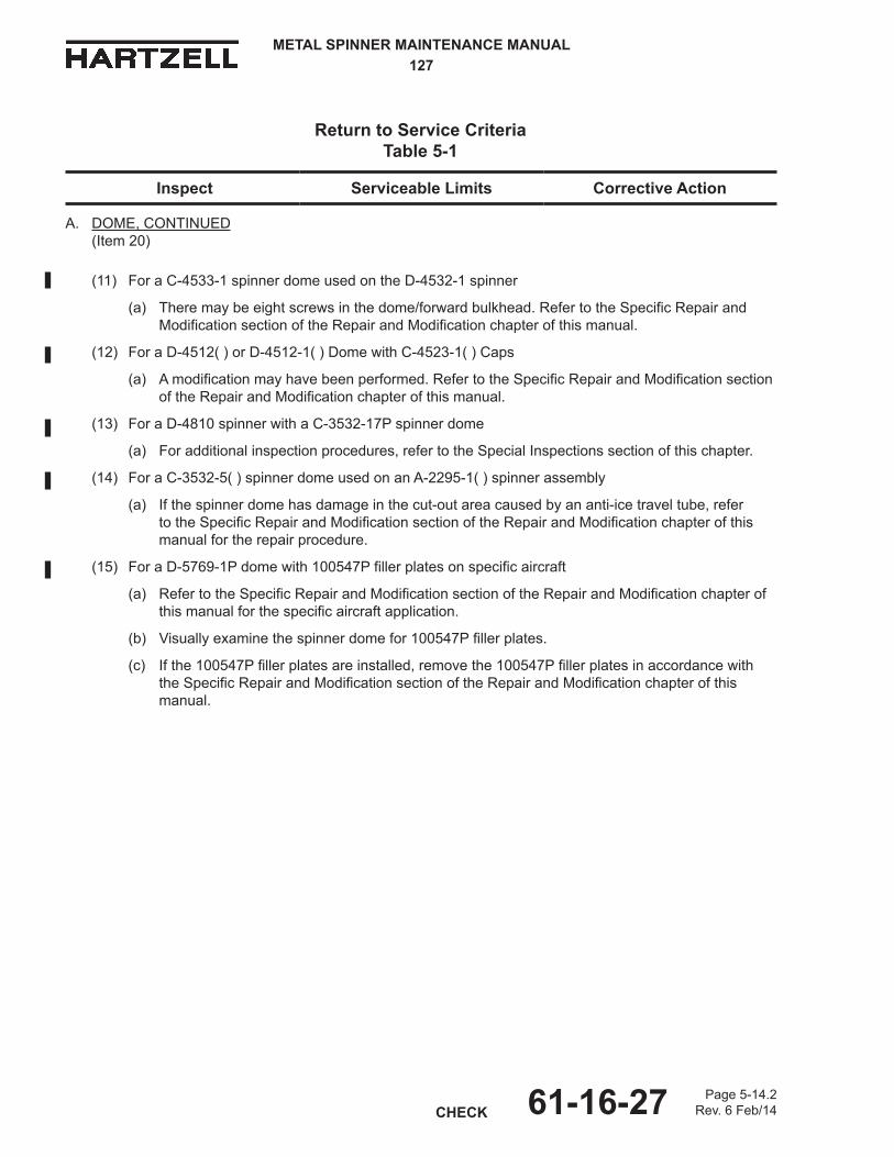
A. DOME, CONTINUED (Item 20)
(11) For a C-4533-1 spinner dome used on the D-4532-1 spinner
(a) Theremaybeeightscrewsinthedome/forwardbulkhead.RefertotheSpecificRepairandModification section of the Repair and Modification chapter of this manual.
(12) For a D-4512( ) or D-4512-1( ) Dome with C-4523-1( ) Caps
(a) A modification may have been performed. Refer to the Specific Repair and Modification section of the Repair and Modification chapter of this manual.
(13) For a D-4810 spinner with a C-3532-17P spinner dome
(a) For additional inspection procedures, refer to the Special Inspections section of this chapter.
(14) For a C-3532-5( ) spinner dome used on an A-2295-1( ) spinner assembly
(a) If the spinner dome has damage in the cut-out area caused by an anti-ice travel tube, refer totheSpecificRepairandModificationsectionoftheRepairandModificationchapterofthismanual for the repair procedure.
(15) For a D-5769-1P dome with 100547P filler plates on specific aircraft
(a) Refer to the Specific Repair and Modification section of the Repair and Modification chapter of this manual for the specific aircraft application.
(b) Visuallyexaminethespinnerdomefor100547Pfillerplates.
(c) Ifthe100547Pfillerplatesareinstalled,removethe100547Pfillerplatesinaccordancewiththe Specific Repair and Modification section of the Repair and Modification chapter of this manual.

METAL SPINNER MAINTENANCE MANUAL127
CHECKPage 5-15
Rev. 6 Feb/1461-16-27
Inspect Serviceable Limits Corrective Action
Return to Service CriteriaTable 5-1
A. DOME, CONTINUED (Item 20)(16) For the D-5769-1( ) spinner dome
(a) A modification may have been performed.
(b) Refer to the Specific Repair and Modification section of the Repair and Modification chapter of this manual for the specific aircraft application.
(c) Ifthespinnerdome,P/N102965(),ortheforwardbulkheadP/N102963,andthespacer, P/N 102987, have not been installed, perform a pre-flight inspection of the spinner dome for acrackateachspinnerattachmentscrew,inaccordancewithHartzellOwner'sManual115N(61-00-15). Refer to the Specific Repair and Modification section of the Repair and Modification chapter of this manual.
WARNING: DO NOT OPERATE THE AIRCRAFT WITH A CRACKED SPINNER. FAILURE TO COMPLY MAY RESULT IN DEATH, SERIOUS BODILY INJURY, AND/OR SUBSTANTIAL PROPERTY DAMAGE.
(d) Ifacrackisfoundduringinspection,replacementofthedamagedD-5769-1()spinnerdomeisrequired before further flight.
1 Refer to the Specific Repair and Modification section of the Repair and Modification chapter of this manual for replacement instructions for the D-5769-1( ) spinner dome.
(e) Ifacrackisnotfoundduringinspection,refertotheSpecificRepairandModificationsectionofthe Repair and Modification chapter of this manual for modification or replacement instructions for the D-5769-1( ) spinner dome.

METAL SPINNER MAINTENANCE MANUAL127
Page 5-16Rev. 3 May/1061-16-27CHECK
Forward Bulkhead Figure 5-5
1D-630-42D-630-4
ForwardBulkheadThatis Bonded to the Dome
Dome
ForwardBulkheadThatisNot Bonded to the Dome
Dome

METAL SPINNER MAINTENANCE MANUAL127
CHECKPage 5-19
Rev. 3 May/1061-16-27
(Thispageisintentionallyblank.)

METAL SPINNER MAINTENANCE MANUAL127
Page 5-20Rev. 6 Feb/1461-16-27CHECK
Spinner Bulkhead Figure 5-6
W10501
Spinner Dome Mounting Area Edge
Radius

METAL SPINNER MAINTENANCE MANUAL127
CHECKPage 5-21
Rev. 6 Feb/1461-16-27
Inspect Serviceable Limits Corrective Action
Return to Service CriteriaTable 5-1
C. BULKHEAD(Item 50) Refer to Figure 5-6
(1) Visually examine the bulkheadforcracks.
(2) Visually examine the bulkheadforscratches,dents, and gouges.
(3) Visually examine the bulkheadforcorrosionorpitting.
(4) For a turbine engine application
(a) Visually examine thebulkheadforroundness in the radius and at the mounting area edge. Refer to Figure 5-6.
(5) For a reciprocating engine application
(a) Visually examine thebulkheadforroundness in the radius and at the mounting area edge. Refer to Figure 5-6.
Cracksarenotpermitted.
Damage that could adversely affect the fit and function is not permitted.
Corrosion is not permitted. The maximum permitted depth of pitting is 0.003 inch (0.08 mm).The maximum permitted depth of pitting within a total accumulated areaof10percentofthebulkheadsurface is 0.005 inch (0.012 mm). The maximum permitted diameter of pitting is 0.063 inch (1.60 mm).
Abulkheadthatisout-of-roundinthe radius or at the mounting area edge is not permitted.
Abulkheadthatisout-of-roundinthe radius or at the mounting area edge is not permitted.
Iftherearecracks,replacethebulkhead.
Refer to the chapter Repair and Modificationinthismanualfortherepair of scratches, dents, and gouges. If the damage affects the fit and function, replace the bulkhead.
Light polishing with an abrasive pad such as CM47 is optional. It is recommended that an aluminum-type automotive polish be applied following polishing with an abrasive pad. If the corrosion or pitting is greater than the permitted serviceable limits, replacethebulkhead.
Straighten the mounting area edge of thebulkhead.If the mounting area edge of the bulkheadcannotbestraightened,replacethebulkhead.If the out-of-round area is in a radius area,replacethebulkhead.
Ifthebulkheadisout-of-roundinthe radius or at the mounting area edge,replacethebulkhead.
NOTE: An A-4203-1( ) spinner assembly that is installed on propeller model HC-C3YF-1R( )F is notinterchangeableonotherpropellerassemblies.Ifitisnecessarytochangethebulkhead,refertothesection"BalanceWeightRequirementsofSpecificPropellerApplications"in the Static and Balance chapter of Hartzell Standard Practice Manual 202A for information about balance weights.

METAL SPINNER MAINTENANCE MANUAL127
Page 5-22Rev. 3 May/1061-16-27CHECK
C-3409, C-3409-1 and C-3030-4 Spinner Bulkheads Figure 5-7
W10525
SideoftheBulkheadFacingtheEngine
5.18 inch (131.5 mm)
6.38 inch (162.0 mm)
Minimum length permitted of the rivnut above the doubler surface is 0.100 inch (2.54 mm).
Circumferential gouges are permitted in this area. Maximum permitted depth of material loss is 0.080 inch (2.03 mm).
METAL SPINNER MAINTENANCE MANUAL127
CHECKPage 5-23
Rev. 6 Feb/1461-16-27
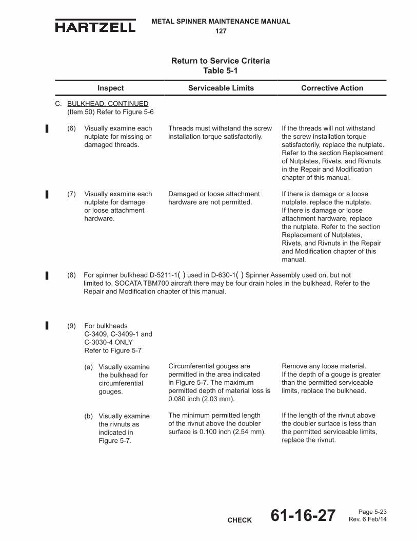
Inspect Serviceable Limits Corrective Action
Return to Service CriteriaTable 5-1
Threads must withstand the screw installation torque satisfactorily.
Damaged or loose attachment hardware are not permitted.
Circumferential gouges are permitted in the area indicated in Figure 5-7. The maximum permitted depth of material loss is 0.080 inch (2.03 mm).
The minimum permitted length of the rivnut above the doubler surface is 0.100 inch (2.54 mm).
If the threads will not withstand the screw installation torque satisfactorily, replace the nutplate. Refer to the section Replacement of Nutplates, Rivets, and Rivnuts intheRepairandModificationchapter of this manual.
If there is damage or a loose nutplate, replace the nutplate. If there is damage or loose attachment hardware, replace the nutplate. Refer to the section Replacement of Nutplates, Rivets, and Rivnuts in the Repair andModificationchapterofthismanual.
Remove any loose material.If the depth of a gouge is greater than the permitted serviceable limits,replacethebulkhead.
If the length of the rivnut above the doubler surface is less than the permitted serviceable limits, replace the rivnut.
C. BULKHEAD, CONTINUED(Item 50) Refer to Figure 5-6
(6) Visually examine each nutplate for missing or damaged threads.
(7) Visually examine each nutplate for damage or loose attachment hardware.
(8) ForspinnerbulkheadD-5211-1( ) used in D-630-1( ) Spinner Assembly used on, but not limitedto,SOCATATBM700aircrafttheremaybefourdrainholesinthebulkhead.RefertotheRepair and Modification chapter of this manual.
(9) Forbulkheads C-3409, C-3409-1 and C-3030-4 ONLY Refer to Figure 5-7
(a) Visually examine thebulkheadforcircumferential gouges.
(b) Visually examine the rivnuts as indicated in Figure 5-7.

METAL SPINNER MAINTENANCE MANUAL127
Page 5-24Rev. 3 May/1061-16-27CHECK
Adapter Ring Unit Figure 5-8
C-885
Starter Ring Gear Mounting Holes
Spinner Dome Mounting Edge
Area Adjacent to the Spinner Dome Mounting Edge

METAL SPINNER MAINTENANCE MANUAL127
CHECKPage 5-45
Rev. 6 Feb/1461-16-27
Component Inspection Criteria Table 5-1
Inspect Serviceable Limits Corrective ActionJ. BULKHEAD SPACER
(Item 310)Refer to Figure 5-14.
(1) Visually examine the bulkheadspacerforcorrosion.
Corrosion is not permitted. Remove corrosion using glass bead cleaning. Refer to the Cleaning chapter of Hartzell Standard Practices Manual 202A (61-01-02).
(2) Visually examine the ID bore "A" and ID bore "B" of the bulkheadspacerfornicks,scratches,damage, or pitting.
The maximum permitted depth ofanick,scratch,damage,orpitting is 0.002 inch (0.05 mm). The maximum permitted diameter of an individual pit is 0.062 inch (1.57 mm). Linear pitting is not permitted.
Repair is permitted to a maximum depth of 0.003 inch (0.07 mm). The maximum permitted total damage and repair of ID bore "A" and ID bore "B" is 25 percent of each circumference. If the bulkheadspacerisnotwithin the serviceable limits or the corrective action limits, replace thebulkheadspacer.
(3) Visually examine the ID of each through hole ofthebulkheadspacerfornicks,scratches,damage, or pitting.
The maximum permitted depth of anick,scratch,damage,orpittingis 0.002 inch (0.05 mm). The maximum permitted diameter of an individual pit is 0.062 inch (1.57 mm). The maximum permitted total accumulated area ofnicks,scratches,damage,or pitting is 25 percent of the through hole. Linear pitting is not permitted.
Repair is permitted to a maximum depth of 0.004 inch (0.10 mm). Damage or repair must not affect thefitofthespacerwiththematingparts. If the spacer is not within the serviceable limits or the corrective action limits, replace the spacer.
(4) Measure the ID of each through hole of the bulkheadspacer.
The maximum permitted ID is 0.3175 inch (8.064 mm). This doesnotincludenicks,scratches,damage, pitting, or repair that is a part of inspection J.(3).
If the ID is greater than the permitted serviceable limits, replacethebulkheadspacer.

METAL SPINNER MAINTENANCE MANUAL127
Page 5-46Rev. 6 Feb/1461-16-27CHECK
Component Inspection Criteria Table 5-1
Inspect Serviceable Limits Corrective ActionJ. BULKHEAD SPACER
CONTINUED(Item 310)Refer to Figure 5-14.
(5) Visually examine mounting flange surface "C" and mounting flange surface "D" of thebulkheadspacerfornicks,scratches,gouges, pitting, or other damage.
The maximum permitted depth of anick,scratch,gouge,pitting,orother damage is 0.002 inch (0.05 mm). Material may not be pushed up above the undamaged adjacent surfaces. The maximum permitted diameter of an individual pit is 0.062 (1.57 mm). Linear pitting is not permitted.
Repair is permitted to a maximum depth of 0.010 (0.25 mm). The maximum permitted total area of damage and repair for each side is 0.5 square inch (322 sq. mm). The maximum permitted area of an individual repair is 0.25 square inch (161 sq. mm) and must be at least 0.250 inch (6.35 mm) from any other repaired area. If the damage or repair is greater than the permitted serviceable limits or the corrective action limits, replace thebulkheadspacer.
(6) Visually examine the ODofthebulkheadspacerfornicks,scratches, gouges, pitting, or other damage.
The maximum permitted depth of anick,scratch,gouge,pitting,orother damage is 0.004 inch (0.010 mm). The maximum permitted diameter of an individual pit is 0.062 (1.57 mm). The maximum permitted total accumulatedareaofnicks,scratches, damage, or pitting is 0.5 square inch (322 sq. mm). Linear pitting is not permitted.
Repair is permitted to a maximum depth of 0.010 (0.25 mm). The maximum permitted total area of damage and repair is 1.0 square inch (645 sq. mm). If the damage or repair is greater than the permitted serviceable limits or the corrective action limits, replace the bulkheadspacer.
(7) Visually examine both sidesofthebulkheadspacerforthemarkings"Prop Side" and "Engine Side".
Theremustbeamarking"PropSide" on one side and "Engine Side" on the other side of the bulkheadspacer.
Using a round bottom stamp or an electric pencil, apply the words "Prop Side" and "Engine Side" to the applicable mounting surface.Remove any pushed up material using a customer procured whetstone.

METAL SPINNER MAINTENANCE MANUAL127
REPAIR AND MODIFICATIONPage 6-1
Rev. 6 Feb/1461-16-27
REPAIR AND MODIFICATION - CONTENTS
1. General ...............................................................................................................6-3
A. Plating and Welding of Aluminum Spinners ..................................................6-3B. Repair of a Dent ............................................................................................6-3C. Painting .........................................................................................................6-4D. Factory Polish................................................................................................6-4E. Replacement of Nutplates, Rivets, and Rivnuts ............................................6-5F. Stop Drilling of a Crack..................................................................................6-6G.ModificationofaBulkheadforDynamicBalance ..........................................6-6
2. SpecificRepairandModifications.......................................................................6-7A. SpinnerBulkheadModificationforHC-()2Y()-()Propellers .......................6-7B. SpinnerBulkheadModificationforHC-()3Y()-()Propellers .....................6-17C. RemovalofaRidgeontheIDofthe836-57()SpinnerDomeInstalled
on the 690 Rockwell Commander ...............................................................6-21D. Optional Use of Bolts to Replace Bulkhead Rivet
on the 836-15R Spinner Assembly ..............................................................6-23E. Installing Filler Plates on C-3043-2, -3 Spinners ........................................6-25F. Filler Plate Replacement ............................................................................6-26G.ModificationtoDrainWaterfromtheD-630-1()Spinner ...........................6-29H. AdditionofScrewstoC-4533-1SpinnerDomeUsed
on the D-4532-1 Spinner Assembly ............................................................6-31I. ModificationofC-4523-2()CapsandD-4512()or
D-4512-2()SpinnerDomes .......................................................................6-33J. Repair of Spinner Dome Damage Caused by Interference
with an Anti-ice Travel Tube ........................................................................6-37K. Spinner Bulkhead Requirements to Maintain Propeller Balance ...............6-39L. ModificationofaD-5555-1(L)()BulkheadforSynchrophaserHardware
and Dynamic Balance .................................................................................6-41M. Replacing the Spinner Dome Unit and Dome Cap
With a One Piece Spinner Dome ................................................................6-49N. Removalofthe100547()FillerPlates
Usedwiththe835-54()SpinnerAssembly ................................................6-52O.ReplacementorModificationoftheD-5769-1()SpinnerDome
onthe835-54()SpinnerAssembly .............................................................6-55P. ModificationoftheD-6448-3(P)SpinnerBulkhead .....................................6-61Q. Applying the Timing Stripe...........................................................................6-66

METAL SPINNER MAINTENANCE MANUAL127
Page 6-2Rev. 4 Apr/1161-16-27REPAIR AND MODIFICATION
LIST OF FIGURES
Two-bladed Propeller Bulkhead Cutout Dimensions ......................Figure 6-1 .............6-9
Two-bladedPropellerBulkheadModificationTemplate ..................Figure 6-2 ...........6-10
Installing the Bulkhead Mounting Doublers .....................................Figure 6-3 ...........6-12
Three-bladedPropellerBulkheadModificationDimensions ............Figure 6-4 ...........6-18
RemovingtheIDRidgeFromthe836-57()SpinnerDome ............Figure 6-5 ...........6-20
Optional Use of Bolts to Replace the Bulkhead Rivet on the 836-15R Spinner ............................................................Figure 6-6 ...........6-23
C-4238FillerPlateSpecifications...................................................Figure 6-7 ...........6-24
DrillingDrainHolesintheSpinnerBulkhead...................................Figure 6-8 ...........6-28
Wall Thickness.................................................................................Figure 6-9 ...........6-36
Length and Width of the Repair .......................................................Figure 6-10 .........6-37
LocationofHolesforDynamicBalanceWeights .............................Figure 6-11 .........6-42
LocationofHolesforSynchrophaserSystem .................................Figure 6-12 .........6-44
Dimensions for Synchrophaser System ..........................................Figure 6-13 .........6-45
HexNutConfiguration .....................................................................Figure 6-14 .........6-48
A Cutaway View of the Spinner Dome .............................................Figure 6-15 .........6-56
D-5769-1 Spinner Dome, 102963 Front Bulkhead, and 102987 Spacer ....................................................................Figure 6-16 .........6-58
SpinnerBulkheadD-6448-3Modification ........................................Figure 6-17 .........6-60
TimingStripeSpecifications ............................................................Figure 6-18 .........6-62
LIST OF TABLES
SpinnerBulkheadsThatMaybeModified (Two-bladedPropellers) .............................................................Table 6-1 ..............6-8
SpinnerBulkheadsThatCannotbeModifiedand MustbeReplacedWhenaNewHubisInstalled .......................Table 6-2 ............6-15
SpinnerAssembliesThatCannotbeModifiedand MustbeReplacedWhenaNewHubisInstalled .......................Table 6-3 ............6-15
SpinnerBulkheadsThatMaybeModified (Three-bladedPropellers) ..........................................................Table 6-4 ............6-16

METAL SPINNER MAINTENANCE MANUAL127
REPAIR AND MODIFICATIONPage 6-3
Rev. 6 Feb/1461-16-27
WARNING: DONOTATTEMPTINTHEFIELDANYREPAIR,REPLACEMENT,REWORKORPROCEDURENOTSPECIFICALLYAUTHORIZEDBYHARTZELLPROPELLERINC.ORNOTSPECIFICALLYREFERREDTOINHARTZELLMANUALS.CONTACTTHEHARTZELLPRODUCTSUPPORTDEPARTMENTFORGUIDANCEABOUTTHEAIRWORTHINESSOFANYPARTWITHUNUSUALWEARORDAMAGE.
1. General
A. Plating and Welding of Aluminum Spinners
(1) Plating,chromeplating,welding,orcold-weldmetalepoxyofanytypeisnotpermitted as a repair of a spinner component.
B. Repair of a Dent
CAUTION: AHIGHAMOUNTOFMETALMOVEMENTCANRESULTINFORMATION OF A CRACK. IF A CRACK DEVELOPS, REFER TO CRACKLIMITSFORSPINNERDOMESINTABLE5-1INTHECHECKCHAPTEROFTHISMANUAL.
(1) Spinner Dome Dent Repair
(a) Usinganon-metallichammerandacontouredblock,restoretheoriginalcontour by striking the internal side lightly with a hammer while holding a smoothcontouredblockontheexternalside.
CAUTION: IFTHEORIGINALCONTOURCANNOTBEESTABLISHEDORIFMORETHAN0.008INCH(0.20MM)OFTHEORIGINALTHICKNESSISLOST,REPLACETHESPINNERDOME.
(b) Smooththerepairedareawithemeryclothorequivalent.
(c) Usea320to400gritabrasiveclothtoprepareexternalsurfacesforahighlusterfinishifdesired.
(d) Forahighlusterfinishonexternalsurfaces,polishtherepairedareausinganautomotivetypealuminumfinishmedium.
(2) OtherComponentDentRepair
CAUTION: AHIGHAMOUNTOFMETALMOVEMENTCANRESULTINFORMATIONOFACRACK.INSPECTTHESUBJECTCOMPONENT FOR CRACKS AFTER REMOVING DENTS.
(a) Usinganon-metallichammerandasmoothcontouredblock,restoretheoriginalcontourbystrikingtheoppositeside(sideoppositethatwhichwascontactedbythedentingforce)lightlywithahammerwhileholdingasmooth contoured block on the opposite side.
(b) Smooththerepairedareawithemeryclothorequivalent.

METAL SPINNER MAINTENANCE MANUAL127
Page 6-4Rev. 6 Feb/1461-16-27REPAIR AND MODIFICATION
C. Painting
(1) Ifthespinnerdomehasnotbeenpolished,itmaybepaintedbeforeinstallationon the aircraft, if desired.
(a) Paintonlytheareasofthebulkheadthatwillbeexposedwhenthespinnerdome is installed.
(2) Ifthespinnerdomehasbeenpolished,itmaybepaintedifdesired.
(a) Makesurethattheserialnumberisvisibleafterpainting.
(3) RefertothePaintandFinishchapterofHartzellStandardPracticesManual202A(61-01-02)forrecommendedgeneralpaintingguidelines.
(4) PaintingRecommendations
(a) Using280gritorfinersandpaper,lightlysandthesurfacestobepainted.
(b) UsingaclothsoakedwithsolventsuchasMEKCM106,MPKCM219,orlacquer thinner, wipe the sanded surface.
(c) Permitthesolventtodry.
(d) Masktheareasthatwillnotbepainted.
(e) Applyawashprimer,suchasHartzellwashprimerMix#3.
(f) Applypainttoarecommendedfullcompletedcoverageof2to4milsdrythickness of paint.
NOTE: HartzellrecommendsusingSherwin-WilliamsPolanepaint.
(5) TimingStripe
(a) Whenmanufactured,atimingstripewasappliedtoHartzellbulkheadsthathave the following part numbers:
1 C-3064-9()
2 D-3474-1()
3 D-4801()
4 D-5241()
(b) Forinstructionsaboutapplyingthetimingstripe,refertothesection"Applying the Timing Stripe" in this chapter.

METAL SPINNER MAINTENANCE MANUAL127
REPAIR AND MODIFICATIONPage 6-5
Rev. 6 Feb/1461-16-27
D. Factory Polish
CAUTION: POLISHINGINTHEFIELDISNOTRECOMMENDED.
(1) If a polished spinner dome is desired, when ordering add the letter "P" to the end of the part number to indicate a high luster factory polish.
(a) Polishinginthefieldisextremelylaborintensiveandtheresultsmaybeunpredictable.
(2) HartzellPropellerInc.willnotre-polishanycomponentofaspinner assembly.
E. Replacement of Nutplates, Rivets, and Rivnuts
CAUTION: DONOTMAKETHEHOLEOVERSIZEWHENDRILLINGOUTTHERIVET.
(1) Usingtheappropriatedrillbit,drillouttherivet.
(2) Replacethenutplateand/orrivetand/orrivnutinaccordancewiththeprocedures in the FAA Advisory Circular 43.13-1B.
(3) Thefollowingisalistofnutplatesthatmaybereplaced.
(a) B-3849-08 Nutplate,floating,(stainless)(b) B-3849-3 Nutplate,floating(c) B-3846-3 Nutplate,fixed(d) B-3858-3 Nutplate,fixed,cres(stainless)(e) B-6983 Nutplate,floating,acorn(f) B-7052-3 Nutplate,fixed
(4) Thefollowingisalistofrivetsthatmaybereplaced.
(a) B-3847-() Rivet,100°head,0.094aluminum(b) B-3848-() Rivet,100°head,0.125aluminum(c) B-3861-() Rivet,universalhead,0.125aluminum(d) B-3862-() Rivet,universalhead,0.188aluminum(e) B-3863-() Rivet,universalhead,0.250aluminum(f) B-6673-0306 Rivet,100°head,pop-type
(5) Thefollowingisalistofrivnutsthatmaybereplaced.
(a) B-7333-75 Rivnut,aluminum(b) B-7333-120 Rivnut,aluminum(c) B-7333-200 Rivnut,aluminum

METAL SPINNER MAINTENANCE MANUAL127
Page 6-6Rev. 3 May/1061-16-27REPAIR AND MODIFICATION
F. Stop Drilling of a Crack
(1) General
(a) Thisprocedureprovidesamethodtoperformastopdrillprocedureforacrack in the spinner assembly.
(b) RefertotheCheckchapterofthismanualforserviceablelimits.
CAUTION: REMOVETHEPARTFROMTHEPROPELLERBEFOREPERFORMINGTHESTOPDRILLINGPROCEDURE.
(2) Procedure
CAUTION: DONOTDRILLMORETHANONEHOLEATTHEENDOFACRACK.
(a) Usinga1/8inchdrillbit,drillaholeattheendofthecracktominimizefurther cracking.
(b) Drillingmorethanoneholeattheendofacrackisnotpermitted.
(c) Deburrthenewlydrilledhole.
(3) ContinuedOperation
(a) Inspectthestopdrilledcrackbeforeeachflight.
(b) Ifthecrackcontinuesbeyondthestopdrilledhole,nofurtherflightispermitted and the part must be replaced.
G.ModificationofaBulkheadforDynamicBalance
(1) Chadwick-HelmuthManualAW-9511-2,"TheSmoothPropeller",specifiesseveral generic bulkhead rework procedures. These are satisfactory if they complywiththeconditionsspecifiedintheStaticandDynamicBalancechapterofHartzellStandardPracticesManual202A(61-01-02).

METAL SPINNER MAINTENANCE MANUAL127
REPAIR AND MODIFICATIONPage 6-67
Rev. 6 Feb/1461-16-27
(g) Applyayellowstripeontheblackbandinaccordancewitheither Method 1, Paint Procedure or Method 2, Label Procedure.
1 Method 1 - Paint Procedure
a Apply masking material as necessary for the Polane® yellow (Mix#10)paintstripe.RefertotheapplicablepageofFigure6-18.
b Apply Polane®yellow(Mix#10)painttoresultinayellowstripeon the bulkhead. Refer to the applicable page of Figure 6-18.
c Permit the Polane®yellow(Mix#10)painttodry.
d Remove the masking material from the bulkhead.
2 Method 2 - Label Procedure
CAUTION: ADHESIONOFTHEYELLOWTAPECM160MUSTBECONTINOUSACROSSTHEEDGEOFTHEBULKHEADDOUBLER,WHEREAPPLICABLE.
NOTE: It is easier to cut the yellow tape CM160 to length after applying it to the bulkhead, than to try to apply a precut piece of yellow tape CM160 to the bulkhead.
a Apply yellow tape CM160 in accordance with the applicable page of Figure 6-18.
b Cut the yellow tape CM160 to the correct length, if necessary.
c Applymaskingmaterial0.500inch(12.70mm)awayfromaround the edges of the yellow tape CM160.
d Apply a layer of clear protective spray CM129 over the yellow tape CM160.
e Permit the clear protective spray CM129 to dry.
f Remove the masking material from the bulkhead.

METAL SPINNER MAINTENANCE MANUAL127
Page 6-68Rev. 6 Feb/1461-16-27REPAIR AND MODIFICATION
(Thispageisintentionallyblank.)

METAL SPINNER MAINTENANCE MANUAL127
ILLUSTRATED PARTS LISTPage 10.3-47Rev. 5 Feb/1361-16-27
EFFECTIVITY MODEL EFFECTIVITY MODEL
-ITEM NOT ILLUSTRATED
1 2 3 4 5 6 7
FIG./ITEMNUMBER
PARTNUMBER
AIRLINESTOCK NUMBER
NOMENCLATURE EFF.CODE
UPA O/H
10.3-4 -10 837-16( ) SPINNER ASSEMBLY 20 C-226-1( ) • DOME, 3-BLADE 1 50 C-1399-3( ) • BULKHEAD UNIT 1 200 B-3845-8 • SCREW, 10-32, TRUSS HEAD (DOME MOUNTING) 12 Y 210 A-1020 • WASHER, FIBER 12 Y
10.3-4 -10 837-17( ) SPINNER ASSEMBLY 20 C-226-1( ) • DOME, 3-BLADE 1 50 D-3758( ) • BULKHEAD UNIT 1 200 B-3845-8 • SCREW, 10-32, TRUSS HEAD (DOME MOUNTING) 12 Y 210 A-1020 • WASHER, FIBER 12 Y
10.3-3 -10 101468( ) SPINNER ASSEMBLY 20 101467( ) • DOME UNIT, 3-BLADE 1 50 101462( ) • BULKHEAD UNIT 1 90 101465( ) • FILLER PLATE UNIT 1 200 B-3845-8 • SCREW, 10-32, TRUSS HEAD (DOME MOUNTING) 30 Y 210 A-1020 • WASHER, FIBER 30 Y
10.3-3 -10 101468-1( ) SPINNER ASSEMBLY 20 101467-1( ) • DOME UNIT, 3-BLADE 1 50 101462( ) • BULKHEAD UNIT 1 90 101465-1( ) • FILLER PLATE UNIT 3 200 B-3845-8 • SCREW, 10-32, TRUSS HEAD (DOME MOUNTING) 30 Y 210 A-1020 • WASHER, FIBER 30 Y
10.3-3 -10 101468-2( ) SPINNER ASSEMBLY 20 101467-2( ) • DOME UNIT, 3-BLADE 1 50 101462( ) • BULKHEAD UNIT 1 90 101465-2( ) • FILLER PLATE UNIT 3 200 B-3845-8 • SCREW, 10-32, TRUSS HEAD (DOME MOUNTING) 36 Y 210 A-1020 • WASHER, FIBER 36 Y
10.3-3 -10 105012( ) SPINNER ASSEMBLY 20 D-6751( ) • DOME UNIT, 3-BLADE 1 50 105011( ) • BULKHEAD UNIT 1 200 B-3845-8 • SCREW, 10-32, TRUSS HEAD (DOME MOUNTING) 18 Y 210 A-1020 • WASHER, FIBER 18 Y
Spinners - Three-Bladed Propellers

METAL SPINNER MAINTENANCE MANUAL127
Page 10.3-48Rev. 6 Feb/1461-16-27ILLUSTRATED PARTS LIST
EFFECTIVITY MODEL EFFECTIVITY MODEL
-ITEM NOT ILLUSTRATED
1 2 3 4 5 6 7
FIG./ITEMNUMBER
PARTNUMBER
AIRLINESTOCK NUMBER
NOMENCLATURE EFF.CODE
UPA O/H
10.3-3 -10 105298( ) SPINNER ASSEMBLY 20 C-3004-2() • DOME, 3-BLADE 1 50 105297( ) • • BULKHEAD UNIT 1 210 A-1020 • WASHER, FIBER 15 Y 200 B-3845-8 • SCREW, 10-32, TRUSS HEAD (DOME MOUNTING) 15 Y
-10 104781( ) SPINNER ASSEMBLY 20 D-7266-4( ) • DOME UNIT, 3-BLADE 1 30 104262 • MOUNT, FORWARD BULKHEAD 1 50 D-7084-5( ) • BULKHEAD UNIT 1 200 B-3845-8 • SCREW, 10-32, TRUSS HEAD (DOME MOUNTING) 12 Y 210 A-1020 • WASHER, FIBER 12 Y
Spinners - Three-Bladed Propellers

METAL SPINNER MAINTENANCE MANUAL127
ILLUSTRATED PARTS LISTPage 10.4-10.1
Rev. 6 Feb/1461-16-27
EFFECTIVITY MODEL EFFECTIVITY MODEL
-ITEM NOT ILLUSTRATED
1 2 3 4 5 6 7
FIG./ITEMNUMBER
PARTNUMBER
AIRLINESTOCK NUMBER
NOMENCLATURE EFF.CODE
UPA O/H
10.4-3 -10 D-630-10( ) SPINNER ASSEMBLY ** 20 D-5210-5( ) • DOME, CNC MACHINED, 4-BLADE 1 30 C-5292 • FORWARD BULKHEAD 1 50 D-5211-6( ) • BULKHEAD UNIT, CNC MACHINED 1 200 B-3845-8 • SCREW, 10-32, TRUSS HEAD (DOME MOUNTING) 20 Y 210 A-1020 • WASHER, FIBER 20 Y -220 B-632 • SPACER 15 Y
10.4-3 -10 D-630-11( ) SPINNER ASSEMBLY ** 20 D-5210-5( ) • DOME, CNC MACHINED, 4-BLADE 1 30 C-5292 • FORWARD BULKHEAD 1 50 D-5211-7( ) • BULKHEAD UNIT, CNC MACHINED 1 200 B-3845-8 • SCREW, 10-32, TRUSS HEAD (DOME MOUNTING) 20 Y 210 A-1020 • WASHER, FIBER 20 Y -220 B-632 • SPACER 15 Y
**For information about the effectivity of CNC parts, refer to the Description and Operation chapter of this manual.
Spinners - Four-Bladed Propeller

Page 10.4-10.2Rev. 6 Feb/1461-16-27ILLUSTRATED PARTS LIST
METAL SPINNER MAINTENANCE MANUAL127
(This page is intentionally blank.)

METAL SPINNER MAINTENANCE MANUAL127
ILLUSTRATED PARTS LISTPage 10.4-19Rev. 6 Feb/1461-16-27
EFFECTIVITY MODEL EFFECTIVITY MODEL
-ITEM NOT ILLUSTRATED
1 2 3 4 5 6 7
FIG./ITEMNUMBER
PARTNUMBER
AIRLINESTOCK NUMBER
NOMENCLATURE EFF.CODE
UPA O/H
10.4-2 -10 D-5519-2( ) SPINNER ASSEMBLY 20 D-5210-1( ) • DOME, 4-BLADE 1 50 D-5521-2( ) • BULKHEAD UNIT 1 90 C-5522 • • FILLER PLATE 4 200 B-3845-8 • SCREW, 10-32, TRUSS HEAD (DOME MOUNTING) 20 Y 210 B-3851-0332 • WASHER 20 Y
10.4-2 -10 D-5547( ) SPINNER ASSEMBLY 20 D-5548( ) • DOME, 4-BLADE 1 30 C-5596 • FORWARD BULKHEAD 1 50 D-5549( ) • BULKHEAD UNIT 1 90 C-5588 • • FILLER PLATE 4 200 B-3845-8 • SCREW, 10-32, TRUSS HEAD (DOME MOUNTING) 20 Y 210 B-3851-0332 • WASHER 20 Y -220 B-632 • SPACER 15 Y
10.4-2 -10 D-5547-1( ) SPINNER ASSEMBLY 20 D-5548( ) • DOME, 4-BLADE 1 30 C-5596 • FORWARD BULKHEAD 1 50 D-5549-1( ) • BULKHEAD UNIT 1 90 C-5588 • • FILLER PLATE 4 200 B-3845-8 • SCREW, 10-32, TRUSS HEAD (DOME MOUNTING) 20 Y 210 B-3851-0332 • WASHER 20 Y -220 B-632 • SPACER 15 Y
10.4-3 -10 D-5710( ) SPINNER ASSEMBLY 20 D-5714( ) • DOME, 4-BLADE 1 30 C-5718 • FORWARD BULKHEAD 1 50 E-5715( ) • BULKHEAD UNIT 1 200 B-3845-8 • SCREW, 10-32, TRUSS HEAD (DOME MOUNTING) 20 Y 210 A-1020 • WASHER, FIBER 20 Y -220 B-632 • SPACER 15 Y
Spinners - Four-Bladed Propeller

METAL SPINNER MAINTENANCE MANUAL127
Page 10.4-20Rev. 6 Feb/1461-16-27ILLUSTRATED PARTS LIST
EFFECTIVITY MODEL EFFECTIVITY MODEL
-ITEM NOT ILLUSTRATED
1 2 3 4 5 6 7
FIG./ITEMNUMBER
PARTNUMBER
AIRLINESTOCK NUMBER
NOMENCLATURE EFF.CODE
UPA O/H
Spinners - Four-Bladed Propeller
10.4-3 -10 D-5710-2( ) SPINNER ASSEMBLY 20 D-5714( ) • DOME, 4-BLADE 1 30 C-5718 • FORWARD BULKHEAD 1 50 E-5715-2( ) • BULKHEAD UNIT 1 200 B-3845-9 • SCREW, 10-32, TRUSS HEAD (DOME MOUNTING) 20 Y ALTERNATE IS ITEM 200A, POST HC-SL-61-331 200A B-3845-8 • SCREW, 10-32, TRUSS HEAD (DOME MOUNTING) ALTERNATE FOR ITEM 200, PRE HC-SL-61-331 20 Y 210 A-1020 • WASHER, FIBER 20 Y -220 B-632 • SPACER 15 Y
10.4-3 -10 D-5710-3( ) SPINNER ASSEMBLY 20 D-5714( ) • DOME, 4-BLADE 1 30 C-5718 • FORWARD BULKHEAD 1 50 E-5715-3( ) • BULKHEAD UNIT 1 200 B-3845-9 • SCREW, 10-32, TRUSS HEAD (DOME MOUNTING) 20 Y ALTERNATE IS ITEM 200A, POST HC-SL-61-331 200A B-3845-8 • SCREW, 10-32, TRUSS HEAD (DOME MOUNTING) ALTERNATE FOR ITEM 200, PRE HC-SL-61-331 20 Y 210 A-1020 • WASHER, FIBER 20 Y -220 B-632 • SPACER 15 Y
10.4-3 -10 D-5710-4( ) SPINNER ASSEMBLY 20 D-5714-1( ) • DOME, 4-BLADE 1 30 C-5718 • FORWARD BULKHEAD 1 50 E-5715-4( ) • BULKHEAD UNIT 1 200 B-3845-8 • SCREW, 10-32, TRUSS HEAD (DOME MOUNTING) 20 Y 210 A-1020 • WASHER, FIBER 20 Y -220 B-632 • SPACER 15 Y
10.4-3 -10 D-5798( ) SPINNER ASSEMBLY 20 D-5799( ) • DOME UNIT, 4-BLADE 1 50 C-3409-1( ) • BULKHEAD UNIT 1 200 B-3845-8 • SCREW, 10-32, TRUSS HEAD (DOME MOUNTING) 16 Y 210 A-1020 • WASHER, FIBER 16 Y

METAL SPINNER MAINTENANCE MANUAL127
ILLUSTRATED PARTS LISTPage 10.4-21Rev. 6 Feb/1461-16-27
EFFECTIVITY MODEL EFFECTIVITY MODEL
-ITEM NOT ILLUSTRATED
1 2 3 4 5 6 7
FIG./ITEMNUMBER
PARTNUMBER
AIRLINESTOCK NUMBER
NOMENCLATURE EFF.CODE
UPA O/H
Spinners - Four-Bladed Propeller
10.4-2 -10 E-6963( ) SPINNER ASSEMBLY 20 D-7274( ) • DOME, 4-BLADE 1 30 C-7275 • FORWARD BULKHEAD 1 50 D-7273( ) • BULKHEAD UNIT 1 90 D-7278 • • FILLER PLATE 4 200 B-3845-8 • SCREW, 10-32, TRUSS HEAD (DOME MOUNTING) 20 Y 210 A-1020 • WASHER, FIBER 20 Y -220 B-632 • SPACER 15 Y
10.4-2 -10 E-6963-1( ) SPINNER ASSEMBLY 20 E-7341( ) • DOME, 4-BLADE 1 30 C-7275 • FORWARD BULKHEAD 1 50 D-7273( ) • BULKHEAD UNIT 1 90 D-7278 • • FILLER PLATE 4 200 B-3845-8 • SCREW, 10-32, TRUSS HEAD (DOME MOUNTING) 20 Y 210 A-1020 • WASHER, FIBER 20 Y -220 B-632 • SPACER 15 Y
10.4-3 -10 100635( ) SPINNER ASSEMBLY 20 100633( ) • DOME, CNC MACHINED, 4-BLADE 1 50 100631( ) • BULKHEAD UNIT, CNC MACHINED 1 200 B-3845-8 • SCREW, 10-32, TRUSS HEAD (DOME MOUNTING) 24 Y 210 A-1020 • WASHER, FIBER 24 Y
10.4-2 -10 101384( ) SPINNER ASSEMBLY 20 D-5560-1( ) • DOME, 4-BLADE 1 30 C-5562 • FORWARD BULKHEAD 1 50 101385( ) • BULKHEAD UNIT 1 90 101389 • FILLER PLATE 4 200 B-3845-8 • SCREW, 10-32, TRUSS HEAD (DOME MOUNTING) 32 Y 210 A-1020 • WASHER, FIBER 32 Y 220 B-632 • SPACER 15 Y

METAL SPINNER MAINTENANCE MANUAL127
Page 10.4-22Rev. 6 Feb/1461-16-27ILLUSTRATED PARTS LIST
EFFECTIVITY MODEL EFFECTIVITY MODEL
-ITEM NOT ILLUSTRATED
1 2 3 4 5 6 7
FIG./ITEMNUMBER
PARTNUMBER
AIRLINESTOCK NUMBER
NOMENCLATURE EFF.CODE
UPA O/H
10.4-2 -10 103788( ) SPINNER ASSEMBLY 20 103783( ) • DOME, 4-BLADE 1 30 C-5596 • FORWARD BULKHEAD 1 50 103789( ) • BULKHEAD UNIT 1 90 103781 • • FILLER PLATE 4 200 B-3845-8 • SCREW, 10-32, TRUSS HEAD (DOME MOUNTING) 32 Y 210 A-1020 • WASHER, FIBER 32 Y 220 B-632 • SPACER 15 Y
10.4-2 -10 103956( ) SPINNER ASSEMBLY 20 D-4528( ) • DOME, 4-BLADE 1 50 D-4880( ) • BULKHEAD UNIT 1 200 B-3845-8 • SCREW, 10-32, TRUSS HEAD (DOME MOUNTING) 20 Y 210 A-1020 • WASHER, FIBER 20 Y 220 B-632 • SPACER 10 Y
10.5-2 -10 104553( ) SPINNER ASSEMBLY 20 104550( ) • DOME, 5-BLADE, CNC MACHINED 1 -30 105477 • FORWARD BULKHEAD 1 50 104551( ) • BULKHEAD UNIT, CNC MACHINED 1 210 A-1020 • WASHER, FIBER 20 Y 200 B-3845-8 • SCREW, 10-32, TRUSS HEAD (DOME MOUNTING) 20 Y -220 B-632 • SPACER 15 Y
Spinners - Four-Bladed Propeller

METAL SPINNER MAINTENANCE MANUAL127
ILLUSTRATED PARTS LISTPage 10.5-9
Rev. 3 May/1061-16-27
EFFECTIVITY MODEL EFFECTIVITY MODEL
-ITEM NOT ILLUSTRATED
1 2 3 4 5 6 7
FIG./ITEMNUMBER
PARTNUMBER
AIRLINESTOCK NUMBER
NOMENCLATURE EFF.CODE
UPA O/H
Spinners - Five-Bladed Propeller
10.5-1 -10 D-5574-1( ) SPINNER ASSEMBLY 20 D-5576( ) • DOME, 5-BLADE 1 50 D-5577-1( ) • BULKHEAD UNIT 1 90 C-5578-1 • • FILLER PLATE 5 200 B-3845-8 • SCREW, 10-32, TRUSS HEAD (DOME MOUNTING) 20 Y 210 A-1020 • WASHER, FIBER 20 Y
10.5-1 -10 D-5597-1( ) SPINNER ASSEMBLY 20 D-5598( ) • DOME, 5-BLADE 1 30 D-2825 • FORWARD BULKHEAD 1 50 D-5599-3( ) • BULKHEAD UNIT 1 90 C-2878-1 • • BULKHEAD FILLER PLATE 5 200 B-3845-8 • SCREW, 10-32, TRUSS HEAD (DOME MOUNTING) 30 Y 210 B-3851-0332 • WASHER 30 Y -220 B-5486 • SPACER , MOUNTING, SPINNER 4
10.5-1 -10 E-5760( ) SPINNER ASSEMBLY 20 E-5761( ) • DOME, 5-BLADE 1 50 E-5762( ) • BULKHEAD UNIT 1 90 C-5764 • • FILLER PLATE 5 210 A-1020 • WASHER, FIBER 30 Y 200 B-3845-8 • SCREW, 10-32, TRUSS HEAD (DOME MOUNTING) 30 Y
10.5-1 -10 E-6955( ) SPINNER ASSEMBLY 20 D-5576( ) • DOME, 5-BLADE 1 50 E-6956( ) • BULKHEAD UNIT 1 90 C-5578 • • FILLER PLATE 5 210 A-1020 • WASHER, FIBER 20 Y 200 B-3845-8 • SCREW, 10-32, TRUSS HEAD (DOME MOUNTING) 20 Y
10.5-2 -10 E-7256( ) SPINNER ASSEMBLY 20 D-1687( ) • DOME, 5-BLADE 1 50 E-7257( ) • BULKHEAD UNIT 1 210 A-1020 • WASHER, FIBER 20 Y 200 B-3845-8 • SCREW, 10-32, TRUSS HEAD (DOME MOUNTING) 20 Y

METAL SPINNER MAINTENANCE MANUAL127
Page 10.5-10Rev. 6 Feb/1461-16-27ILLUSTRATED PARTS LIST
EFFECTIVITY MODEL EFFECTIVITY MODEL
-ITEM NOT ILLUSTRATED
1 2 3 4 5 6 7
FIG./ITEMNUMBER
PARTNUMBER
AIRLINESTOCK NUMBER
NOMENCLATURE EFF.CODE
UPA O/H
10.5-2 -10 104478( ) SPINNER ASSEMBLY 20 D-1687-2( ) • DOME, 5-BLADE 1 50 104477( ) • BULKHEAD UNIT 1 210 A-1020 • WASHER, FIBER 20 Y 200 B-3845-8 • SCREW, 10-32, TRUSS HEAD (DOME MOUNTING) 20 Y
10.5-2 -10 104236( ) SPINNER ASSEMBLY 20 D-1687( ) • DOME, 5-BLADE 1 50 104237( ) • BULKHEAD UNIT 1 210 A-1020 • WASHER, FIBER 20 Y 200 B-3845-8 • SCREW, 10-32, TRUSS HEAD (DOME MOUNTING) 20 Y
10.5-2 -10 104552( ) SPINNER ASSEMBLY 20 105044( ) • DOME, 5-BLADE 1 -30 104152 • FORWARD BULKHEAD 1 50 104154( ) • BULKHEAD UNIT 1 210 A-1020 • WASHER, FIBER 20 Y 200 B-3845-8 • SCREW, 10-32, TRUSS HEAD (DOME MOUNTING) 20 Y -220 B-5486 • SPACER, MOUNTING, SPINNER 15
10.5-2 -10 105180( ) SPINNER ASSEMBLY 20 105176( ) • DOME, 5-BLADE 1 -30 105181 • FORWARD BULKHEAD 1 50 105178( ) • BULKHEAD UNIT 1 210 A-1020 • WASHER, FIBER 15 Y 200 B-3845-8 • SCREW, 10-32, TRUSS HEAD (DOME MOUNTING) 15 Y -220 B-5486 • SPACER, MOUNTING, SPINNER 15
Spinners - Five-Bladed Propeller