hartzell propeller inc. one propeller place piqua, ohio...
TRANSCRIPT
MANUAL REVISION TRANSMITTALManual 180 (30-61-80)
Propeller Ice Protection System ManualREVISION 24 dated May 2017
Attached is a copy of Revision 24 to Hartzell Propeller Inc. Manual 180.
Page Control Chart for Revision 24
Remove Insert Chapter/Page No. Chapter/Page No.COVER COVER cover page and cover back cover page and cover backREVISION HIGHLIGHTS REVISION HIGHLIGHTS pages 1 thru 4 pages 1 thru 4LIST OF EFFECTIVE PAGES LIST OF EFFECTIVE PAGES pages 1 thru 8 pages 1 thru 8ILLUSTRATED PARTS LIST ILLUSTRATED PARTS LIST pages 10-1 and 10-2 pages 10-1 and 10-2 pages 10-5 and 10-6 pages 10-5 and 10-6 pages 10.4-3 and 10.4-4 pages 10.4-3 and 10.4-4 pages 10.4-11 thru 10.4-20.2 pages 10.4-11 thru 10.4-20.4 pages 10.4-33 thru 10.4-38 pages 10.4-33 and 10.4-38 pages 10.4-63 thru 10.4-70 pages 10.4-63 thru 10.4-70 pages 10.12-3 and 10.12-4 pages 10.12-3 and 10.12-4 pages 10.12-4.1 and 10.12-4.2, insert after page10.12-4 pages 10.12-61 thru 10.12-64 page 10.12-61 thru 10.12-64
NOTE 1: When the manual revision has been inserted in the manual, record the information required on the Record of Revisions pages in this manual.
NOTE 2: Pages distributed in this revision may include pages from previous revisions if they are on the opposite side of revised pages. This is done as a convenience to those users who wish to print a two-sided copy of the new revision.
HARTZELL PROPELLER INC.One Propeller PlacePiqua, Ohio 45356-2634 U.S.A.Telephone: 937.778.4200Fax: 937.778.4215
This page may be discarded after proper filing of the revision.

(This page is intentionally blank.)

Manual No. 18030-61-80Revision 24May 2017
Hartzell Propeller Inc.One Propeller PlacePiqua, Ohio 45356-2634 U.S.A.Phone: 937.778.4200Fax: 937.778.4215
Propeller Ice Protection System Manual

COVER 30-61-80 Inside Cover Rev. 24 May/17
PROPELLER ICE PROTECTION SYSTEM MANUAL180
© 2006, 2007, 2008, 2009, 2010, 2011, 2012, 2013, 2014, 2015, 2016, 2017 Hartzell Propeller Inc. - All rights reserved

Page 1 Rev. 24 May/17
PROPELLER ICE PROTECTION SYSTEM MANUAL180
REVISION HIGHLIGHTS 30-61-80
REVISION 24 HIGHLIGHTS COVER
• Revised to match the manual revision
REVISION HIGHLIGHTS • Revised to match the manual revision
LIST OF EFFECTIVE PAGES • Revised to match the manual revision
ILLUSTRATED PARTS LIST • Section 10.4 Added a Caution statement about correct tie strap routing where applicable.
Revised Installation Instruction 10.4-G
Revised Figure 10.4-5.2, "Wire Harness-to-Blade Shank/Counterweight"
Revised Figure 10.4-5.3, "Wire Harness-to-Blade Shank/Counterweight"
Revised Figure 10.4-5.5, "Wire Harness-to-Blade Shank/Counterweight"
Revised Figure 10.4-6, "Slip Ring Mounting"
Removed Figure 10.4-6.1, "Slip Ring Mounting"
Revised the parts list for propeller de-ice kit, 106049
Added the parts list for propeller de-ice kit, 106818
Made other language/format changes
• Section 10.12 Added the parts list for airframe de-ice kit, 106592
Added the parts list for airframe de-ice kit, 106819
Made other language/format changes

Page 2 Rev. 24 May/17
PROPELLER ICE PROTECTION SYSTEM MANUAL180
REVISION HIGHLIGHTS 30-61-80
(This page is intentionally blank.)

Page 3 Rev. 24 May/17
PROPELLER ICE PROTECTION SYSTEM MANUAL180
REVISION HIGHLIGHTS 30-61-80
REVISION 24 HIGHLIGHTS
1. Introduction
A. General
(1) This is a list of the current revisions that have been issued against this manual. Please compare to the RECORD OF REVISIONS page to make sure that all revisions have been added to the manual.
B. Components
(1) Revision No. indicates the revisions incorporated in this manual.
(2) Issue Date is the date of the revision.
(3) Comments indicates the level of the revision.
(a) New Issue is a new manual distribution. The manual is distributed in its entirety. All the revision dates are the same and no change bars are used.
(b) Reissue is a revision to an existing manual that includes major content and/or major format changes. The manual is distributed in its entirety. All revision dates are the same and no change bars are used.
(c) Major Revision is a revision to an existing manual that includes major content or minor format changes over a large portion of the manual. The manual is distributed in its entirety. All the revision dates are the same, but change bars are used to indicate the changes incorporated in the latest revision of the manual.
(d) Minor Revision is a revision to an existing manual that includes minor content changes to the manual. Only the revised pages of the manual are distributed. Each page retains the date and the change bars associated with the last revision to that page.

Page 4 Rev. 24 May/17
PROPELLER ICE PROTECTION SYSTEM MANUAL180
REVISION HIGHLIGHTS 30-61-80
Revision No. Issue Date Comments Original Jul/06 New Issue 1 Nov/06 Major Revision 2 Jun/07 Major Revision 3 Feb/08 Minor Revision 4 Jan/09 Minor Revision 5 Apr/09 Minor Revision 6 Aug/09 Major Revision 7 Dec/09 Minor Revision 8 Apr/10 Minor Revision 9 Jul/10 Minor Revision 10 Feb/11 Minor Revision 11 Jun/11 Minor Revision 12 Oct/11 Minor Revision 13 Jun/12 Minor Revision 14 Jan/13 Minor Revision 15 May/13 Minor Revision 16 Oct/13 Minor Revision 17 Dec/13 Minor Revision 18 Mar/14 Minor Revision 19 May/15 Minor Revision 20 Dec/15 Minor Revision 21 Aug/16 Minor Revision 22 Nov/16 Minor Revision 23 Feb/17 Minor Revision 24 May/17 Minor Revision

Page 1 Rev. 24 May/17
PROPELLER ICE PROTECTION SYSTEM MANUAL180
LIST OF EFFECTIVE PAGES 30-61-80
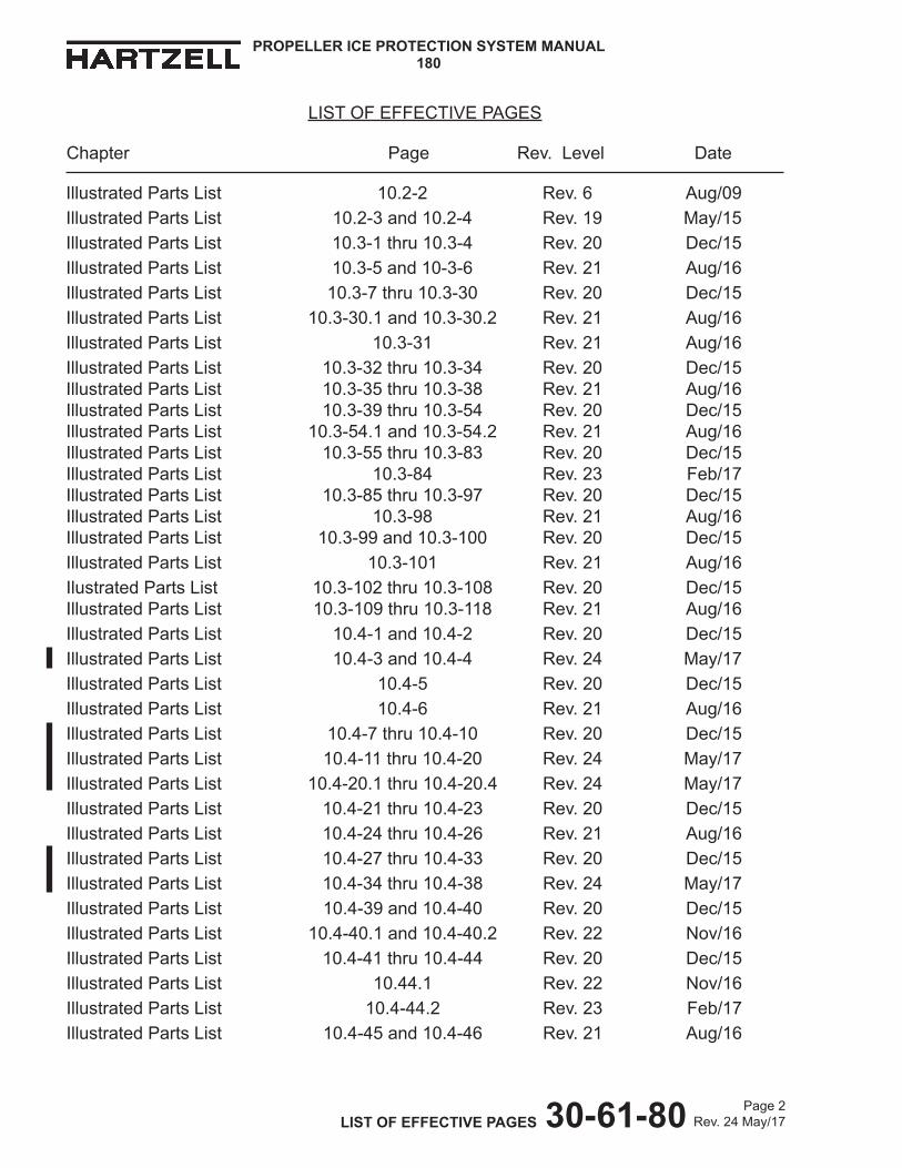
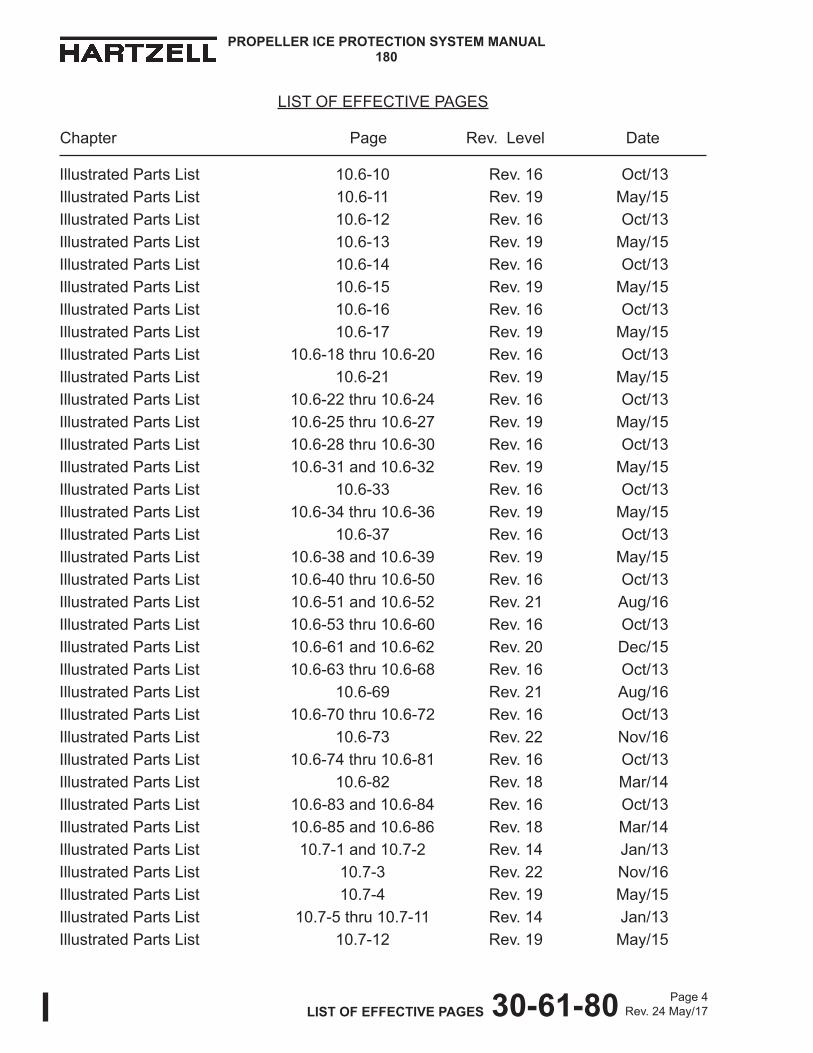
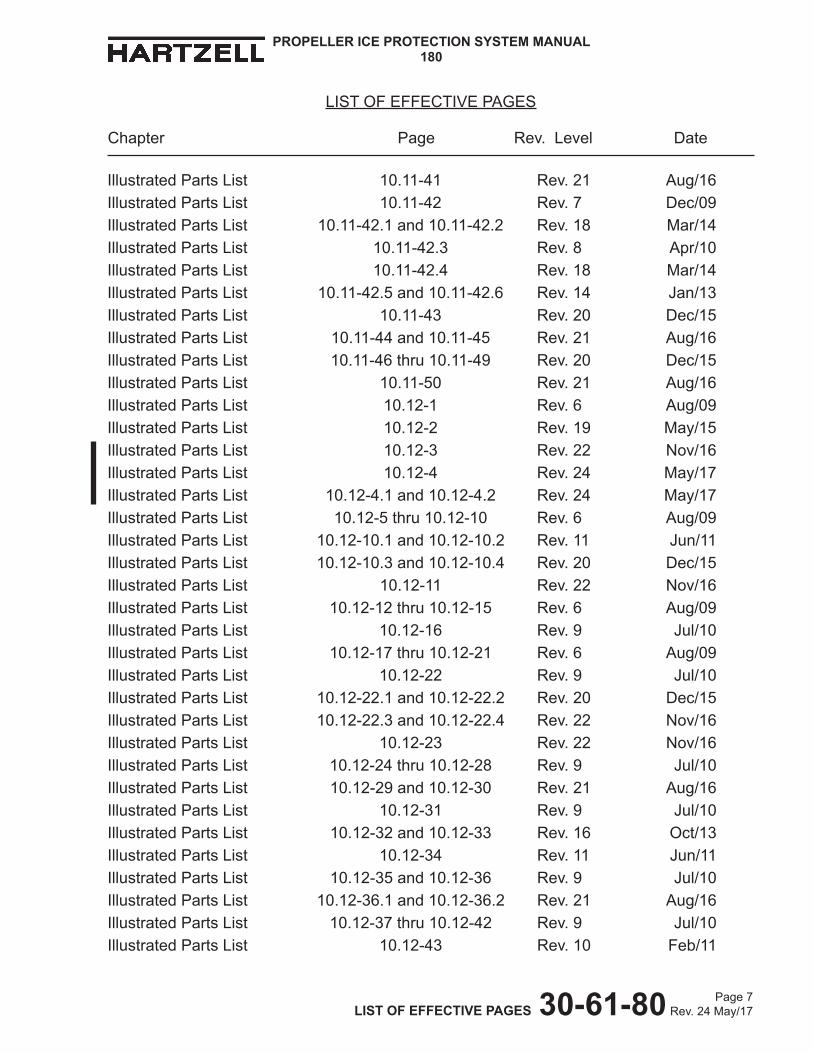
LIST OF EFFECTIVE PAGES
Chapter Page Rev. Level Date
Cover/Cover Back Cover/Inside Cover Rev. 24 May/17Revision Highlights 1 thru 4 Rev. 24 May/17Record of Revisions 1 and 2 Rev. 2 Jun/07Record of Temporary Revisions 1 and 2 Rev. 19 May/15Service Document List 1 and 2 Rev. 23 Feb/17Airworthiness Limitations 1 and 2 Rev. 2 Jun/07List of Effective Pages 1 thru 8 Rev. 24 May/17Table of Contents 1 and 2 Rev. 19 May/15Introduction 1 Rev. 20 Dec/15Introduction 2 thru 4 Rev. 14 Jan/13Introduction 5 thru 7 Rev. 21 Aug/16Introduction 8 Rev. 20 Dec/15Introduction 9 thru 12 Rev. 14 Jan/13Description and Operation 1 thru 4 Rev. 2 Jun/07Testing and Fault Isolation 1-1 and 1-2 Rev. 19 May/15Automatic Test Requirements 2-1 and 2-2 Rev. 19 May/15Disassembly 3-1 and 3-2 Rev. 19 May/15Cleaning 4-1 and 4-2 Rev. 19 May/15Check 5-1 and 5-2 Rev. 19 May/15Repair/Modification 6-1and6-2 Rev.19 May/15Assembly 7-1 and 7-2 Rev. 19 May/15Fits and Clearances 8-1 and 8-2 Rev. 19 May/15Special Tools, Fixtures, and Equipment 9-1 and 9-2 Rev. 19 May/15Illustrated Parts List 10-1 Rev. 21 Aug/16Illustrated Parts List 10-2 Rev. 24 May/17Illustrated Parts List 10-3 and 10-4 Rev. 22 Nov/16Illustrated Parts List 10-5 Rev. 21 Aug/16Illustrated Parts List 10-6 Rev. 24 May/17Illustrated Parts List 10-7 thru 10-9 Rev. 22 Nov/16Illustrated Parts List 10-10 Rev. 20 Dec/15Illustrated Parts List 10-11 Rev. 22 Nov/16Illustrated Parts List 10-12 Rev. 17 Dec/13Illustrated Parts List 10.1-1 Rev. 19 May/15Illustrated Parts List 10.1-2 Rev. 6 Aug/09Illustrated Parts List 10.2-1 Rev. 19 May/15
Page 2 Rev. 24 May/17
PROPELLER ICE PROTECTION SYSTEM MANUAL180
LIST OF EFFECTIVE PAGES 30-61-80
LIST OF EFFECTIVE PAGES
Chapter Page Rev. Level Date
Illustrated Parts List 10.2-2 Rev. 6 Aug/09Illustrated Parts List 10.2-3 and 10.2-4 Rev. 19 May/15Illustrated Parts List 10.3-1 thru 10.3-4 Rev. 20 Dec/15Illustrated Parts List 10.3-5 and 10-3-6 Rev. 21 Aug/16Illustrated Parts List 10.3-7 thru 10.3-30 Rev. 20 Dec/15Illustrated Parts List 10.3-30.1 and 10.3-30.2 Rev. 21 Aug/16Illustrated Parts List 10.3-31 Rev. 21 Aug/16Illustrated Parts List 10.3-32 thru 10.3-34 Rev. 20 Dec/15 Illustrated Parts List 10.3-35 thru 10.3-38 Rev. 21 Aug/16 Illustrated Parts List 10.3-39 thru 10.3-54 Rev. 20 Dec/15 Illustrated Parts List 10.3-54.1 and 10.3-54.2 Rev. 21 Aug/16 Illustrated Parts List 10.3-55 thru 10.3-83 Rev. 20 Dec/15 Illustrated Parts List 10.3-84 Rev. 23 Feb/17 Illustrated Parts List 10.3-85 thru 10.3-97 Rev. 20 Dec/15 Illustrated Parts List 10.3-98 Rev. 21 Aug/16 Illustrated Parts List 10.3-99 and 10.3-100 Rev. 20 Dec/15Illustrated Parts List 10.3-101 Rev. 21 Aug/16Ilustrated Parts List 10.3-102 thru 10.3-108 Rev. 20 Dec/15 Illustrated Parts List 10.3-109 thru 10.3-118 Rev. 21 Aug/16Illustrated Parts List 10.4-1 and 10.4-2 Rev. 20 Dec/15Illustrated Parts List 10.4-3 and 10.4-4 Rev. 24 May/17Illustrated Parts List 10.4-5 Rev. 20 Dec/15Illustrated Parts List 10.4-6 Rev. 21 Aug/16Illustrated Parts List 10.4-7 thru 10.4-10 Rev. 20 Dec/15Illustrated Parts List 10.4-11 thru 10.4-20 Rev. 24 May/17Illustrated Parts List 10.4-20.1 thru 10.4-20.4 Rev. 24 May/17Illustrated Parts List 10.4-21 thru 10.4-23 Rev. 20 Dec/15Illustrated Parts List 10.4-24 thru 10.4-26 Rev. 21 Aug/16Illustrated Parts List 10.4-27 thru 10.4-33 Rev. 20 Dec/15Illustrated Parts List 10.4-34 thru 10.4-38 Rev. 24 May/17Illustrated Parts List 10.4-39 and 10.4-40 Rev. 20 Dec/15Illustrated Parts List 10.4-40.1 and 10.4-40.2 Rev. 22 Nov/16Illustrated Parts List 10.4-41 thru 10.4-44 Rev. 20 Dec/15Illustrated Parts List 10.44.1 Rev. 22 Nov/16Illustrated Parts List 10.4-44.2 Rev. 23 Feb/17Illustrated Parts List 10.4-45 and 10.4-46 Rev. 21 Aug/16

Page 3 Rev. 24 May/17
PROPELLER ICE PROTECTION SYSTEM MANUAL180
LIST OF EFFECTIVE PAGES 30-61-80
LIST OF EFFECTIVE PAGES
Chapter Page Rev. Level Date
Illustrated Parts List 10.4-47 thru 10.4-49 Rev. 20 Dec/15Illustrated Parts List 10.4-50 Rev. 23 Feb/17Illustrated Parts List 10.4-50.1 and 10.4-50.2 Rev. 22 Nov/16Illustrated Parts List 10.4-51 thru 10.4-60 Rev. 20 Dec/15Illustrated Parts List 10.4-61 Rev. 21 Aug/16Illustrated Parts List 10.4-62 and 10.4-63 Rev. 20 Dec/15Illustrated Parts List 10.4-64 thru 10.4-70 Rev. 24 May/17Illustrated Parts List 10.5-1 thru 10.5-4 Rev. 15 May/13Illustrated Parts List 10.5-5 and 10.5-6 Rev. 6 Aug/09Illustrated Parts List 10.5-6.1 and 10.5-6.2 Rev. 19 May/15Illustrated Parts List 10.5-6.3 and 10.5-6.4 Rev. 15 May/13Illustrated Parts List 10.5-7 Rev. 19 May/15Illustrated Parts List 10.5-8 Rev. 11 Jun/11Illustrated Parts List 10.5-9 thru 10.5-12 Rev. 19 May/15 Illustrated Parts List 10.5-12.1 Rev. 14 Jan/13Illustrated Parts List 10.5-12.2 Rev. 19 May/15Illustrated Parts List 10.5-13 Rev. 19 May/15 Illustrated Parts List 10.5-14 Rev. 13 Jun/12 Illustrated Parts List 10.5-14.1 and 10.5-14.2 Rev. 14 Jan/13 Illustrated Parts List 10.5-15 Rev. 14 Jan/13 Illustrated Parts List 10.5-16 Rev. 13 Jun/12Illustrated Parts List 10.5-17 Rev. 19 May/15Illustrated Parts List 10.5-18 Rev. 14 Jan/13 Illustrated Parts List 10.5-19 thru 10.5-26 Rev. 19 May/15Illustrated Parts List 10.5-27 Rev. 13 Jun/12Illustrated Parts List 10.5-28 thru 10.5-32 Rev. 19 May/15Illustrated Parts List 10.6-1 Rev. 16 Oct/13Illustrated Parts List 10.6-2 Rev. 19 May/15Illustrated Parts List 10.6-3 Rev. 22 Nov/16Illustrated Parts List 10.6-4 Rev. 16 Oct/13Illustrated Parts List 10.6-5 Rev. 19 May/15Illustrated Parts List 10.6-6 Rev. 16 Oct/13Illustrated Parts List 10.6-7 Rev. 19 May/15Illustrated Parts List 10.6-8 Rev. 16 Oct/13Illustrated Parts List 10.6-9 Rev. 19 May/15
Page 4 Rev. 24 May/17
PROPELLER ICE PROTECTION SYSTEM MANUAL180
LIST OF EFFECTIVE PAGES 30-61-80
LIST OF EFFECTIVE PAGES
Chapter Page Rev. Level Date
Illustrated Parts List 10.6-10 Rev. 16 Oct/13Illustrated Parts List 10.6-11 Rev. 19 May/15 Illustrated Parts List 10.6-12 Rev. 16 Oct/13Illustrated Parts List 10.6-13 Rev. 19 May/15Illustrated Parts List 10.6-14 Rev. 16 Oct/13Illustrated Parts List 10.6-15 Rev. 19 May/15Illustrated Parts List 10.6-16 Rev. 16 Oct/13Illustrated Parts List 10.6-17 Rev. 19 May/15Illustrated Parts List 10.6-18 thru 10.6-20 Rev. 16 Oct/13Illustrated Parts List 10.6-21 Rev. 19 May/15Illustrated Parts List 10.6-22 thru 10.6-24 Rev. 16 Oct/13Illustrated Parts List 10.6-25 thru 10.6-27 Rev. 19 May/15Illustrated Parts List 10.6-28 thru 10.6-30 Rev. 16 Oct/13Illustrated Parts List 10.6-31 and 10.6-32 Rev. 19 May/15Illustrated Parts List 10.6-33 Rev. 16 Oct/13Illustrated Parts List 10.6-34 thru 10.6-36 Rev. 19 May/15Illustrated Parts List 10.6-37 Rev. 16 Oct/13Illustrated Parts List 10.6-38 and 10.6-39 Rev. 19 May/15Illustrated Parts List 10.6-40 thru 10.6-50 Rev. 16 Oct/13 Illustrated Parts List 10.6-51 and 10.6-52 Rev. 21 Aug/16Illustrated Parts List 10.6-53 thru 10.6-60 Rev. 16 Oct/13Illustrated Parts List 10.6-61 and 10.6-62 Rev. 20 Dec/15Illustrated Parts List 10.6-63 thru 10.6-68 Rev. 16 Oct/13Illustrated Parts List 10.6-69 Rev. 21 Aug/16Illustrated Parts List 10.6-70 thru 10.6-72 Rev. 16 Oct/13Illustrated Parts List 10.6-73 Rev. 22 Nov/16Illustrated Parts List 10.6-74 thru 10.6-81 Rev. 16 Oct/13Illustrated Parts List 10.6-82 Rev. 18 Mar/14 Illustrated Parts List 10.6-83 and 10.6-84 Rev. 16 Oct/13 Illustrated Parts List 10.6-85 and 10.6-86 Rev. 18 Mar/14Illustrated Parts List 10.7-1 and 10.7-2 Rev. 14 Jan/13 Illustrated Parts List 10.7-3 Rev. 22 Nov/16Illustrated Parts List 10.7-4 Rev. 19 May/15Illustrated Parts List 10.7-5 thru 10.7-11 Rev. 14 Jan/13Illustrated Parts List 10.7-12 Rev. 19 May/15

Page 5 Rev. 24 May/17
PROPELLER ICE PROTECTION SYSTEM MANUAL180
LIST OF EFFECTIVE PAGES 30-61-80
LIST OF EFFECTIVE PAGES
Chapter Page Rev. Level Date
Illustrated Parts List 10.7-13 and 10.7-14 Rev. 14 Jan/13Illustrated Parts List 10.7-15 Rev. 18 Mar/14 Illustrated Parts List 10.7-16 Rev. 14 Jan/13Illustrated Parts List 10.7-16.1 and 10.7-16.2 Rev. 22 Nov/16Illustrated Parts List 10.7-17 thru 10.7-20 Rev. 14 Jan/13Illustrated Parts List 10.7-21 Rev. 20 Dec/15Illustrated Parts List 10.7-22 Rev. 14 Jan/13Illustrated Parts List 10.8-1 thru 10.8-3 Rev. 6 Aug/09Illustrated Parts List 10.8-4 thru 10.8-10 Rev. 19 May/15Illustrated Parts List 10.8-10.1 thru 10.8-10.6 Rev. 19 May/15Illustrated Parts List 10.8-11 Rev. 19 May/15Illustrated Parts List 10.8-12 Rev. 6 Aug/09Illustrated Parts List 10.8-13 thru 10.8-18 Rev. 19 May/15Illustrated Parts List 10.8-18.1 thru 10.8-18.6 Rev. 19 May/15Illustrated Parts List 10.8-19 Rev. 6 Aug/09Illustrated Parts List 10.8-20 and 10.8-21 Rev. 19 May/15 Illustrated Parts List 10.8-22 Rev. 6 Aug/09Illustrated Parts List 10.8-22.1 Rev. 19 May/15Illustrated Parts List 10.8-22.2 Rev. 14 Jan/13 Illustrated Parts List 10.8-23 thru 10.8-29 Rev. 6 Aug/09 Illustrated Parts List 10.8-30 Rev. 11 Jun/11 Illustrated Parts List 10.8-31 Rev. 6 Aug/09Illustrated Parts List 10.8-32 Rev. 11 Jun/11 Illustrated Parts List 10.8-33 Rev. 6 Aug/09Illustrated Parts List 10.8-34 thru 10.8-36 Rev. 11 Jun/11 Illustrated Parts List 10.8-37 thru 10.8-39 Rev. 15 May/13Illustrated Parts List 10.8-40 Rev. 19 May/15Illustrated Parts List 10.9-1 and 10.9-2 Rev. 6 Aug/09Illustrated Parts List 10.9-3 Rev. 22 Nov/16Illustrated Parts List 10.9-4 thru 10.9-6 Rev. 19 May/15Illustrated Parts List 10.9-6.1 and 10.9-6.2 Rev. 22 Nov/16Illustrated Parts List 10.9-7 thru 10.9-12 Rev. 19 May/15Illustrated Parts List 10.9-13 Rev. 22 Nov/16Illustrated Parts List 10.9-14 thru 10.9-17 Rev. 6 Aug/09Illustrated Parts List 10.9-18 Rev. 22 Nov/16

Page 6 Rev. 24 May/17
PROPELLER ICE PROTECTION SYSTEM MANUAL180
LIST OF EFFECTIVE PAGES 30-61-80
LIST OF EFFECTIVE PAGES
Chapter Page Rev. Level Date
Illustrated Parts List 10.10-1 and 10.10-2 Rev. 8 Apr/10Illustrated Parts List 10.10-3 and 10.10-4 Rev. 19 May/15Illustrated Parts List 10.10-5 Rev. 8 Apr/10Illustrated Parts List 10.10-6 thru 10.10-8 Rev. 19 May/15Illustrated Parts List 10.10-9 Rev. 8 Apr/10Illustrated Parts List 10.10-10 thru 10.10-23 Rev. 19 May/15Illustrated Parts List 10.10-24 and 10.10-25 Rev. 8 Apr/10Illustrated Parts List 10.10-26 thru 10.10-29 Rev. 19 May/15Illustrated Parts List 10.10-30 thru 10.10-36 Rev. 8 Apr/10Illustrated Parts List 10.10-36.1 thru 10.10-36.5 Rev. 10 Feb/11Illustrated Parts List 10.10-36.6 thru 10.10-36.8 Rev. 19 May/15Illustrated Parts List 10.10-37 thru 10.10-43 Rev. 8 Apr/10Illustrated Parts List 10.10-44 Rev. 13 Jun/12Illustrated Parts List 10.10-45 thru 10.10-56 Rev. 8 Apr/10Illustrated Parts List 10.10-56.1 and 10.10-56.2 Rev. 14 Jan/13 Illustrated Parts List 10.10-57 thru 10.10-62 Rev. 8 Apr/10Illustrated Parts List 10.10-63 Rev. 10 Feb/11Illustrated Parts List 10.10-64 Rev. 19 May/15Illustrated Parts List 10.11-1 Rev. 7 Dec/09Illustrated Parts List 10.11-2 Rev. 19 May/15Illustrated Parts List 10.11-3 Rev. 18 Mar/14 Illustrated Parts List 10.11-4 thru 10.11-11 Rev. 21 Aug/16Illustrated Parts List 10.11-12 thru 10.11-19 Rev. 7 Dec/09Illustrated Parts List 10.11-20 and 10.11-21 Rev. 21 Aug/16Illustrated Parts List 10.11-22 Rev. 18 Mar/14Illustrated Parts List 10.11-22.1 Rev. 20 Dec/15Illustrated Parts List 10.11-22.2 Rev. 8 Apr/10Illustrated Parts List 10.11-22.3 and 10.11-22.4 Rev. 22 Nov/16Illustrated Parts List 10.11-22.5 and 10.11-22.6 Rev. 14 Jan/13Illustrated Parts List 10.11-23 and 10.11-24 Rev. 7 Dec/09Illustrated Parts List 10.11-25 and 10.11-26 Rev. 21 Aug/16Illustrated Parts List 10.11-27 and 10.11-28 Rev. 7 Dec/09Illustrated Parts List 10.11-29 and 10.11-30 Rev. 21 Aug/16Illustrated Parts List 10.11-31 thru 10.11-38 Rev. 7 Dec/09Illustrated Parts List 10.11-39 and 10.11-40 Rev. 10 Feb/11
Page 7 Rev. 24 May/17
PROPELLER ICE PROTECTION SYSTEM MANUAL180
LIST OF EFFECTIVE PAGES 30-61-80
LIST OF EFFECTIVE PAGES
Chapter Page Rev. Level Date
Illustrated Parts List 10.11-41 Rev. 21 Aug/16Illustrated Parts List 10.11-42 Rev. 7 Dec/09Illustrated Parts List 10.11-42.1 and 10.11-42.2 Rev. 18 Mar/14Illustrated Parts List 10.11-42.3 Rev. 8 Apr/10Illustrated Parts List 10.11-42.4 Rev. 18 Mar/14Illustrated Parts List 10.11-42.5 and 10.11-42.6 Rev. 14 Jan/13Illustrated Parts List 10.11-43 Rev. 20 Dec/15Illustrated Parts List 10.11-44 and 10.11-45 Rev. 21 Aug/16Illustrated Parts List 10.11-46 thru 10.11-49 Rev. 20 Dec/15Illustrated Parts List 10.11-50 Rev. 21 Aug/16Illustrated Parts List 10.12-1 Rev. 6 Aug/09Illustrated Parts List 10.12-2 Rev. 19 May/15Illustrated Parts List 10.12-3 Rev. 22 Nov/16 Illustrated Parts List 10.12-4 Rev. 24 May/17Illustrated Parts List 10.12-4.1 and 10.12-4.2 Rev. 24 May/17Illustrated Parts List 10.12-5 thru 10.12-10 Rev. 6 Aug/09Illustrated Parts List 10.12-10.1 and 10.12-10.2 Rev. 11 Jun/11 Illustrated Parts List 10.12-10.3 and 10.12-10.4 Rev. 20 Dec/15Illustrated Parts List 10.12-11 Rev. 22 Nov/16Illustrated Parts List 10.12-12 thru 10.12-15 Rev. 6 Aug/09Illustrated Parts List 10.12-16 Rev. 9 Jul/10Illustrated Parts List 10.12-17 thru 10.12-21 Rev. 6 Aug/09Illustrated Parts List 10.12-22 Rev. 9 Jul/10Illustrated Parts List 10.12-22.1 and 10.12-22.2 Rev. 20 Dec/15Illustrated Parts List 10.12-22.3 and 10.12-22.4 Rev. 22 Nov/16 Illustrated Parts List 10.12-23 Rev. 22 Nov/16Illustrated Parts List 10.12-24 thru 10.12-28 Rev. 9 Jul/10Illustrated Parts List 10.12-29 and 10.12-30 Rev. 21 Aug/16Illustrated Parts List 10.12-31 Rev. 9 Jul/10 Illustrated Parts List 10.12-32 and 10.12-33 Rev. 16 Oct/13 Illustrated Parts List 10.12-34 Rev. 11 Jun/11 Illustrated Parts List 10.12-35 and 10.12-36 Rev. 9 Jul/10Illustrated Parts List 10.12-36.1 and 10.12-36.2 Rev. 21 Aug/16Illustrated Parts List 10.12-37 thru 10.12-42 Rev. 9 Jul/10Illustrated Parts List 10.12-43 Rev. 10 Feb/11

Page 8 Rev. 24 May/17
PROPELLER ICE PROTECTION SYSTEM MANUAL180
LIST OF EFFECTIVE PAGES 30-61-80
LIST OF EFFECTIVE PAGES
Chapter Page Rev. Level Date
Illustrated Parts List 10.12-44 thru 10.12-50 Rev. 9 Jul/10Illustrated Parts List 10.12-51 thru 10.12-59 Rev. 14 Jan/13Illustrated Parts List 10.12-60 Rev. 19 May/15Illustrated Parts List 10.12-61 Rev. 20 Dec/15Illustrated Parts List 10.12-62 and 10.12-63 Rev. 24 May/17Illustrated Parts List 10.12-64 Rev. 22 Nov/16Illustrated Parts List 10.13-1 and 10.13-2 Rev. 6 Aug/09Illustrated Parts List 10.13-3 Rev. 11 Jun/11 Illustrated Parts List 10.13-4 Rev. 6 Aug/09Illustrated Parts List 10.13-5 Rev. 19 May/15 Illustrated Parts List 10.13-6 thru 10.13-10 Rev. 6 Aug/09Illustrated Parts List 10.13-11 and 10.13-12 Rev. 21 Aug/16Illustrated Parts List 10.13-13 thru 10.13-17 Rev. 11 Jun/11Illustrated Parts List 10.13-18 thru 10.13-23 Rev. 19 May/15 Illustrated Parts List 10.13-24 Rev. 21 Aug/16Illustrated Parts List 10.14-1 and 10.14-2 Rev. 6 Aug/09Illustrated Parts List 10.14-3 and 10.14-4 Rev. 15 May/13Illustrated Parts List 10.15-1 and 10.15-2 Rev. 14 Jan/13Illustrated Parts List 10.15-3 Rev. 20 Dec/15Illustrated Parts List 10.15-4 Rev. 21 Aug/16

Page 10-1Rev. 21 Aug/16 ILLUSTRATED PARTS LIST 30-61-80
PROPELLER ICE PROTECTION SYSTEM MANUAL180
ILLUSTRATED PARTS LIST - CONTENTS
10.1 Introduction .................................................................................................. 10.1-1
A. General ................................................................................................... 10.1-1
B. Using the Illustrated Parts List ................................................................ 10.1-1
10.2 The Illustrated Parts List .............................................................................. 10.2-1
A. Detailed Parts List .................................................................................. 10.2-1
B. Revisions ................................................................................................ 10.2-2
C. Vendors .................................................................................................. 10.2-3
10.3 De-ice Kits for Lightweight Turbine Propellers with Aluminum Blades .................................................................................. 10.3-1
1. General ................................................................................................... 10.3-2
2. Installation Instruction ............................................................................. 10.3-7
A. Installation Instruction 10.3-A ............................................................ 10.3-7
B. Installation Instruction 10.3-B ............................................................ 10.3-8
C. Installation Instruction 10.3-C ............................................................ 10.3-9
D. Installation Instruction 10.3-D .......................................................... 10.3-10
E. Installation Instruction 10.3-E .......................................................... 10.3-12
F. Installation Instruction 10.3-F .......................................................... 10.3-13
G. Installation Instruction 10.3-G ......................................................... 10.3-14
H. Installation Instruction 10.3-H .......................................................... 10.3-16
I. Installation Instruction 10.3-I ........................................................... 10.3-17
J. Installation Instruction 10.3-J .......................................................... 10.3-18
K. Installation Instruction 10.3-K .......................................................... 10.3-20
L. Installation Instruction 10.3-L .......................................................... 10.3-21
M. Installation Instruction 10.3-M ......................................................... 10.3-23
N. Installation Instruction 10.3-N .......................................................... 10.3-25
O. Installation Instruction 10.3-O ......................................................... 10.3-26
P. Installation Instruction 10.3-P .......................................................... 10.3-28
Q. Installation Instruction 10.3-Q ......................................................... 10.3-30
R. Installation Instruction 10.3-R ....................................................... 10.3-30.2
Page 10-2Rev. 24 May/17 ILLUSTRATED PARTS LIST 30-61-80
PROPELLER ICE PROTECTION SYSTEM MANUAL180
10.4 De-ice Kits for Lightweight Turbine Propellers with Composite Blades ................................................................................ 10.4-1
1. General ................................................................................................... 10.4-2 2. Installation Instruction ............................................................................. 10.4-5 A. Installation Instruction 10.4-A ............................................................ 10.4-5 B. Installation Instruction 10.4-B ............................................................ 10.4-7 C. Installation Instruction 10.4-C ............................................................ 10.4-9 D. Installation Instruction 10.4-D ...........................................................10.4-11 E. Installation Instruction 10.4-E .......................................................... 10.4-13 F. Installation Instruction 10.4-F .......................................................... 10.4-15 G. Installation Instruction 10.4-G ......................................................... 10.4-17 H. Installation Instructions 10.4-H ........................................................ 10.4-19 I. Installation Instructions 10.4-I ...................................................... 10.4-20.2
10.5 De-ice Kits for Steel Hub Turbine Propellers with Terminal Clamp Assembly on Clamp .................................................... 10.5-1
1. General ................................................................................................... 10.5-2 2. Installation Instruction ............................................................................. 10.5-4 A. Installation Instuction 10.5-A ............................................................. 10.5-4
10.6 De-ice Kits for Steel Hub Turbine Propellers with Quick Disconnect ........... 10.6-1 1. General ................................................................................................... 10.6-2 2. Installation Instruction ............................................................................. 10.6-5 A. Installation Instruction 10.6-A ............................................................ 10.6-5 B. Installation Instruction 10.6-B ............................................................ 10.6-7 C. Installation Instruction 10.6-C ............................................................ 10.6-9 D. Installation Instruction 10.6-D ...........................................................10.6-11 E. Installation Instruction 10.6-E .......................................................... 10.6-13 F. Installation Instruction 10.6-F .......................................................... 10.6-15 G. Installation Instruction 10.6-G ......................................................... 10.6-17
10.7 De-ice Kits for Steel Hub Turbine Propellers with Terminal Block on Counterweight ......................................................... 10.7-1
1. General ................................................................................................... 10.7-3 2. Installation Instruction ............................................................................. 10.7-4 A. Installation Instruction 10.7-A ............................................................ 10.7-4
ILLUSTRATED PARTS LIST - CONTENTS

Page 10-5Rev. 21 Aug/16 ILLUSTRATED PARTS LIST 30-61-80
PROPELLER ICE PROTECTION SYSTEM MANUAL180
10.3 De-ice Kits for Lightweight Turbine Propellers with Aluminum Blades
TerminalStripHardwareConfigurations: Bulkhead Mounted .................................................Figure 10.3-1 ........... 10.3-32
TerminalStripHardwareConfigurations: Counterweight Mounted .........................................Figure 10.3-1.1 ........ 10.3-34
TerminalStripLeadWireConfigurations: Bulkhead Mounted .................................................Figure 10.3-2 ........... 10.3-35
TerminalStripLeadWireConfigurations: Counterweight Mounted .........................................Figure 10.3-2.1 ........ 10.3-39
LoopClamptoBulkheadHardwareConfigurations ....Figure 10.3-3 ........... 10.3-40
Loop Clamp to Counterweight HardwareConfigurations .......................................Figure 10.3-3.1 ........ 10.3-41
Terminal Strip and Loop Clamp to Bulkhead Attachment .........................................Figure 10.3-4 ........... 10.3-42
Wire Harness to Counterweight ..................................Figure 10.3-5 ........... 10.3-43
Wire Harness to Counterweight ...................................Figure 10.3-5.1 ........ 10.3-44
Wire Harness to Counterweight ...................................Figure 10.3-5.2 ........ 10.3-45
Wire Harness to Counterweight ...................................Figure 10.3-5.3 ........ 10.3-46
Wire Harness to Counterweight ...................................Figure 10.3-5.4 ........ 10.3-47
Wire Harness to Counterweight ...................................Figure 10.3-5.5 ........ 10.3-48
Wire Harness to Counterweight ...................................Figure 10.3-5.6 ........ 10.3-50
Wire Harness to Counterweight ...................................Figure 10.3-5.7 ........ 10.3-51
Wire Harness to Counterweight ...................................Figure 10.3-5.8 ........ 10.3-52
Wire Harness to Counterweight ...................................Figure 10.3-5.9 ........ 10.3-53
Wire Harness to Counterweight ...................................Figure 10.3-5.10 ...... 10.3-54
Wire Harness-to-Counterweight ...................................Figure 10.3-5.11 ... 10.3-54.1
Slip Ring Mounting .......................................................Figure 10.3-6 ........... 10.3-55
Slip Ring Mounting .......................................................Figure 10.3-6.1 ........ 10.3-56
Slip Ring Mounting .......................................................Figure 10.3-6.2 ........ 10.3-57
Slip Ring Mounting .......................................................Figure 10.3-6.3 ........ 10.3-58
Slip Ring Mounting .......................................................Figure 10.3-6.4 ........ 10.3-59
WireHarnessBracketHardwareConfigurations .........Figure 10.3-7 ........... 10.3-60
Wire Harness to De-ice Bracket ...................................Figure 10.3-8 ........... 10.3-61
Wire Harness to De-ice Bracket ...................................Figure 10.3-8.1 ........ 10.3-62
ILLUSTRATED PARTS LIST - FIGURES
Page 10-6Rev. 24 May/17 ILLUSTRATED PARTS LIST 30-61-80
PROPELLER ICE PROTECTION SYSTEM MANUAL180
Wire Harness to De-ice Bracket ...................................Figure 10.3-8.2 ........ 10.3-63 Loop Clamp Orientation ...............................................Figure 10.3-9 ........... 10.3-64 Loop Clamp Orientation ...............................................Figure 10.3-9.1 ........ 10.3-65 Loop Clamp Orientation ...............................................Figure 10.3-9.2 ........ 10.3-66 Loop Clamp Orientation ...............................................Figure 10.3-9.3 ........ 10.3-67 De-ice Boot Lead Wires to Hub ...................................Figure 10.3-10 ......... 10.3-68 Lead Clip to Bulkhead ..................................................Figure 10.3-11 ......... 10.3-69 Hub Clamping Bolt Replacement and De-ice Bracket Alignment .......................................Figure 10.3-12 ......... 10.3-70 Wire Harness Tie Strap Location .................................Figure 10.3-13 ......... 10.3-7110.4 De-ice Kits for Lightweight Turbine Propellers with Composite Blades TerminalStripHardwareConfigurations: Bulkhead Mounted .................................................Figure 10.4-1 ........... 10.4-21 TerminalStripHardwareConfigurations: Counterweight Mounted .........................................Figure 10.4-1.1 ........ 10.4-23 TerminalStripLeadWireConfigurations: Bulkhead Mounted .................................................Figure 10.4-2 ........... 10.4-24 TerminalStripLeadWireConfigurations: Counterweight Mounted .........................................Figure 10.4-2.1 ........ 10.4-27 Loop Clamp to Counterweight/Blade Shank HardwareConfigurations .......................................Figure 10.4-3 ........... 10.4-29 LoopClamptoBulkheadHardwareConfigurations .....Figure 10.4-3.1 ........ 10.4-30 Spring Pin Height .........................................................Figure 10.4-4 ........... 10.4-31 Wire Harness to Blade Shank/Counterweight ..............Figure 10.4-5 ........... 10.4-32 Wire Harness to Blade Shank/Counterweight ..............Figure 10.4-5.1 ........ 10.4-33 Wire Harness to Blade Shank/Counterweight ..............Figure 10.4-5.2 ........ 10.4-34 Wire Harness to Blade Shank/Counterweight ..............Figure 10.4-5.3 ........ 10.4-35 Wire Harness to Blade Shank/Counterweight ..............Figure 10.4-5.4 ........ 10.4-36 Wire Harness to Blade Shank ......................................Figure 10.4-5.5 ........ 10.4-37 Slip Ring Mounting .......................................................Figure 10.4-6 ........... 10.4-38 WireHarnessBracketHardwareConfigurations .........Figure 10.4-7 ........... 10.4-39 Wire Harness to Bracket ..............................................Figure 10.4-8 ........... 10.4-40 Wire Harness-to-Bracket ..............................................Figure 10.4-8.1 ..... 10.4-40.1
ILLUSTRATED PARTS LIST - FIGURES

Page 10.4-3Rev.24May/17 ILLUSTRATED PARTS LIST 30-61-80
PROPELLER ICE PROTECTION SYSTEM MANUAL180
Kit Part Number Vendor Approved InstallationInstructions
7931-5E2690-1 Goodrich Corporation 5E2690 Rev. E7931-5E2710-1 Hartzell Propeller Inc. Refer to 1037697931-65-550-1 Goodrich Corporation 7E1633 Rev. K7931-65-550-3 Goodrich Corporation 7E1633 Rev. K7931-65-550-5 Goodrich Corporation 7E1633 Rev. K7931-67-595-1 Goodrich Corporation 7E1678 Rev. G7931-67-680-3 Goodrich Corporation 7E1744 Rev. W7931-67-680-5 Goodrich Corporation 7E1744 Rev. W7931-67-680-6 Goodrich Corporation 7E1744 Rev. W7931-67-740-1 Goodrich Corporation 7E1755 Rev. F103605 Hartzell Propeller Inc. Installation Instruction 10.4-B
Figures: 10.4-1, 10.4-2, 10.4-4, 10.4-5.1, 10.4-6, 10.4-7, 10.4-9.1,
and 10.4-10 103769 Hartzell Propeller Inc. Installation Instruction 10.4-A
Figures: 10.4-1, 10.4-1.1, 10.4-2, 10.4-2.1, 10.4-5, 10.4-6, 10.4-7, 10.4-8,
and 10.4-10.1104264 Hartzell Propeller Inc. Installation Instruction 10.4-C
Figures: 10.4-1, 10.4-1.1, 10.4-2, 10.4-2.1, 10.4-3, 10.4-7, 10.4-8, 10.4-9,
10.4-10, and 10.4-11 105062 Hartzell Propeller Inc. Installation Instruction 10.4-D
Figures: 10.4-1, 10.4-2, 10.4-4, 10.4-5.2, 10.4-5.4, 10.4-6, 10.4-7,
10.4-9.1, and 10.4-10.2105551 Hartzell Propeller Inc. Installation Instruction 10.4-E,
Figures: 10.4-1, 10.4-2, 10.4-4, 10.4-5.2, 10.4-5.4, 10.4-6, 10.4-7,
10.4-9.2, and 10.4-10.3105934 Hartzell Propeller Inc. Installation Instruction 10.4-F
Figures: 10.4-1, 10.4-2, 10.4-3, 10.4-4, 10.4-5.2, 10.4-5.4, 10.4-6, 10.4-7,
10.4-9.3, and 10.4-10.4
De-ice Kits and Approved Installation Instructions for Lightweight Turbine Propellers with Composite Blades
Table 10.4-1

Page 10.4-4Rev.24May/17 ILLUSTRATED PARTS LIST 30-61-80
PROPELLER ICE PROTECTION SYSTEM MANUAL180
Kit Part Number Vendor Approved InstallationInstructions
106049 Hartzell Propeller Inc. Installation Instruction 10.4-G Figures: 10.4-1, 10.4-2, 10.4-3, 10.4-4,
10.4-5.3, 10.4-5.4, 10.4-6, 10.4-7, 10.4-9.2, and 10.4-10.3
106285 Hartzell Propeller Inc. Installation Instruction 10.4-H Figures: 10.4-1, 10.4-2, 10.4-3, 10.4-4,
10.4-5.2, 10.4-5.4, 10.4-6, 10.4-7, 10.4-9.5, and 10.4-10.5
106783 Hartzell Propeller Inc. Installation Instruction 10.4-I Figures: 10.4-1, 10.4-2, 10.4-3, 10.4-4,
10.4-5.5, 10.4-6.1, 10.4-7, 10.4-9.4, and 10.4-10.6
106818 Hartzell Propeller Inc. Installation Instruction 10.4-G Figures: 10.4-1, 10.4-2, 10.4-3, 10.4-4,
10.4-5.3, 10.4-5.4, 10.4-6, 10.4-7, 10.4-9.2, and 10.4-10.3
De-ice Kits and Approved Installation Instructions for Lightweight Turbine Propellers with Composite Blades
Table 10.4-1 (Continued)
Page 10.4-11Rev.24May/17 ILLUSTRATED PARTS LIST 30-61-80
PROPELLER ICE PROTECTION SYSTEM MANUAL180
D.InstallationInstruction10.4-D
(1) Usingthescrew(220),washers(200and210),tappedeyelet(190),theapplicableconfiguration,andFigure10.4-1,attachtheterminalstrip(170)tothebulkhead.
(2) Torquethescrew(220)to10-12In-Lb(22-45N•m).
(3) Usingthescrews(1170),attachtheslipring(1140)andthebulkheadtothehubasshowninFigure10.4-6.
(4) Torqueeachscrew(1170)96-120In-Lb(10.1-13.5N•m).
(5) Completeaslipringrun-outcheckinaccordancewithHartzellPropellerInc.PropellerIceProtectionSystemComponentMaintenanceManual181 (30-60-81).
(6) Installthebracket(1300),spacer(1325),andwashers(1305)onthehubclampingbolt(1315)betweenthehubandthenut.RefertotheapplicableconfigurationinFigure10.4-7.
(7) Alignthebracket(1300)withtheterminalstrip(170)asshownin Figure10.4-10.2.
(8) Torquethehubclampingnutto22-25Ft-Lb(29-33N•m).
(9) Positionthepropellerbladesatreversebladeangle.
(10) Ifrequired,pressthespringpin(905)perpendicularlyintotheholeinthecounterweightasshowninFigure10.4-4.Thespringpin(905)mustextendtoaheightof0.170-0.210inch(4.32-5.33mm).
NOTE: Thecounterweightmayhavebeendrilledforthespringpin(905)ormayhaveanintegral(cast)pininplaceofthespringpin.
(11) Assembletheplugconnectionbetweenthewireharness(890)andthede-iceboot.
(12) Installthewireharness/de-icebootplugconnectionsinthegrooveinthecounterweightagainstthespringpin(905)asshowninFigure10.4-5.2.
(13) Installthetiestrap(910)intheretaininggrooveofthecounterweightandaroundthecounterweight,andbetweenthewiresofthewireharness/de-icebootplugconnection.RefertoFigure10.4-5.2
CAUTION: ROUTINGTHETIESTRAP(910)INCORRECTLYCANCAUSEANELECTRICALSHORTINTHEDE-ICESYSTEM.
(a) Routethetiestrap(910)betweenwires2and3onthede-icebootleadwires.
(b) Routethetiestrap(910)betweenwire1and2onthewireharnessleadwires.

Page 10.4-12Rev.24May/17 ILLUSTRATED PARTS LIST 30-61-80
PROPELLER ICE PROTECTION SYSTEM MANUAL180
(14) Positiontheheadofthetiestrap(910)intheapproximatelocationshownin Figure10.4-5.2.
(15) Makesurethetiestrap(910)isintheretaininggrooveofthecounterweight.
(16) Tightenthetiestrap(910).
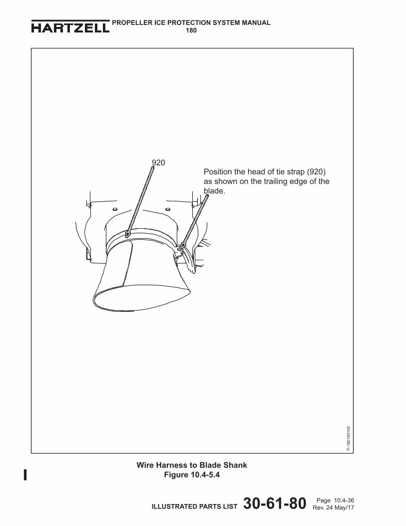
(17) Installthetiestrap(920)aroundthebladeshankandoverthede-icebootleadwiresasshowninFigure10.4-5.4.
(18) Locatetheheadofthetiestrap(920)atthebladetrailingedgeasshowninFigure10.4-5.4.
(19) Tightenthetiestrap(920).
(20) Usingthetiestrap(930),securethede-icebootleadwirestothetiestrap(910)asshowninFigure10.4-5.2.
(21) Installtheclamp(660)aroundthewireharness(890)andagainsttheO-ringasshowninFigure10.4-9.1.
(a) ApplicationofprimerCM127tothethreadsofthescrew(650)andthethreadsoftheholeinthecounterweightisoptional.Ifdesired,applyandpermittodry.
(22) ApplythreadlockerCM116tothethreadsofthescrew(650).
(23) Usingthescrew(650)andwashers(645and630),installtheclamp(660) tothecounterweightinaccordancewiththeapplicableconfigurationand Figure10.4-9.1.
(24) Torquethescrew(650)to15-18In-Lb(1.69-2.03N•m).
(25) Positionthede-icebootleadwireonthebracket(1300)withtheO-ringasshowninFigure10.4-10.2.
(26) Installthetiestraps(840).Twistingoftheleadwiresisnotpermitted.
(27) Installtheslipringleadwiresandde-icewireharness(890)totheterminal strip(170)inaccordancewithFigure10.4-2.
(28) Tightentheterminalscrewsuntilsnug.
(29) Cyclethepropellerfromreverseangletofeatherangletomakesureofproperwireharnessinstallation.Makesurethewireharnessisnotblockedduringcycling.

Page 10.4-13Rev.24May/17 ILLUSTRATED PARTS LIST 30-61-80
PROPELLER ICE PROTECTION SYSTEM MANUAL180
E.InstallationInstruction10.4-E(1) Usingthescrew(220),washers(200and210),tappedeyelet(190),the
applicableconfiguration,andasshowninFigure10.4-1,attachtheterminalstrip(170)tothebulkhead.
(2) Torquethescrew(220)to10-12In-Lb(22-45N•m).(3) Usingthescrews(1170),attachtheslipring(1140)andthebulkheadtothehub
asshowninFigure10.4-6.(4) Torqueeachscrew(1170)96-120In-Lb(10.1-13.5N•m).(5) Completeaslipringrun-outcheckinaccordancewithHartzellPropellerInc.
PropellerIceProtectionSystemComponentMaintenanceManual181 (30-60-81).
(6) Installthebracket(1300),spacer(1325),andwashers(1305)onthehubclampingbolt(1315)betweenthehubandthenut.RefertotheapplicableconfigurationinFigure10.4-7.(a) Installaminimumofonewasher(1305)betweenthehubandthe
bracket(1300).(b) Additionalwashers(1305)maybeusedtogetthecorrectthread
engagementandtomakesurethataminimumofoneexposedthreadisabovethenut.
(7) Alignthecenterlineofthebracket(1300)towardthecenterofthemiddlehubclampingboltasshowninFigure10.4-10.3.
(8) Torquethehubclampingnutto20-22Ft-Lb(28-30N•m).(9) Putthepropellerbladesatreversebladeangle.(10) Ifrequired,pressthespringpin(905)perpendicularlyintotheholeinthe
counterweightasshowninFigure10.4-4.Thespringpin(905)mustextendtoaheightof0.170-0.210inch(4.32-5.33mm).
NOTE: Thecounterweightmayhavebeendrilledforthespringpin(905)ormayhaveanintegral(cast)pininplaceofthespringpin.
(11) Assembletheplugconnectionbetweenthewireharness(890)andthede-iceboot.
(12) Installthewireharness/de-icebootplugconnectionsinthegrooveinthecounterweightagainstthespringpin(905)asshowninFigure10.4-5.2.
(13) Installthetiestrap(910)intheretaininggrooveofthecounterweightandaroundthecounterweight,andbetweenthewiresofthewireharness/de-icebootplugconnection.RefertoFigure10.4-5.2
CAUTION: ROUTINGTHETIESTRAP(910)INCORRECTLYCANCAUSEANELECTRICALSHORTINTHEDE-ICESYSTEM.
(a) Routethetiestrap(910)betweenwires2and3onthede-icebootleadwires.
(b) Routethetiestrap(910)betweenwire1and2onthewireharnessleadwires.

Page 10.4-14Rev.24May/17 ILLUSTRATED PARTS LIST 30-61-80
PROPELLER ICE PROTECTION SYSTEM MANUAL180
(14) Positiontheheadofthetiestrap(910)intheapproximatelocationshownin Figure10.4-5.2.
(15) Makesurethetiestrap(910)isintheretaininggrooveofthecounterweight.
(16) Tightenthetiestrap(910).
(17) Installthetiestrap(920)aroundthebladeshankandoverthede-icebootleadwiresasshowninFigure10.4-5.4.
(18) Locatetheheadofthetiestrap(920)atthebladetrailingedgeasshowninFigure10.4-5.4.
(19) Tightenthetiestrap(920).
(20) Usingthetiestrap(930),securethede-icebootleadwirestothetiestrap(910)asshowninFigure10.4-5.2.
(21) Installtheclamp(660)aroundthewireharness(890)andagainsttheO-ringasshowninFigure10.4-9.2.
(a) ApplicationofprimerCM127tothethreadsofthescrew(650)andthethreadsoftheholeinthecounterweightisoptional.Ifdesired,applyandpermittodry.
(22) ApplythreadlockerCM116tothethreadsofthescrew(650).
(23) Usingthescrew(650)andwashers(645and630),installtheclamp(660)tothecounterweightandperpendiculartothehubsurfaceinaccordancewiththeapplicableconfigurationandFigure10.4-9.2.
(24) Torquethescrew(650)to15-18In-Lb(1.69-2.03N•m).
(25) Positionthede-icebootleadwireonthebracket(1300)withtheO-ringasshowninFigure10.4-10.3.
(26) Installthetiestraps(930).Twistingoftheleadwiresisnotpermitted.
(27) Routethewireharness(890)undertheslipringleadwires(1140)asshowninFigure10.4-10.3.
(28) Attachtheslipringleadwiresandde-icewireharness(890)totheterminalstrip(170)inaccordancewithFigure10.4-2.
(29) Tightentheterminalscrewsuntilsnug.
(30) Cyclethepropellerfromreverseangletofeatherangletomakesureofproperwireharnessinstallation.Makesurethewireharnessisnotblockedduringcycling.
Page 10.4-15Rev.24May/17 ILLUSTRATED PARTS LIST 30-61-80
PROPELLER ICE PROTECTION SYSTEM MANUAL180
F.InstallationInstruction10.4-F(1) Usingthescrew(220),washers(200and210),tappedeyelet(190),andthe
applicableconfigurationshowninFigure10.4-1,attachtheterminalstrip(170)tothebulkhead.(a) Torquethescrew(220)to10-12In-Lb(22-45N•m).
(2) Usingthescrews(1170),attachtheslipring(1140)andthebulkheadtothehubasshowninFigure10.4-6.(a) Torqueeachscrew(1170)96-120In-Lb(10.1-13.5N•m).
(3) Completeaslipringrun-outcheckinaccordancewithHartzellPropellerInc.PropellerIceProtectionSystemComponentMaintenanceManual181 (30-60-81).
(4) Putthepropellerbladesatreversebladeangle.(5) Ifrequired,pressthespringpin(905)perpendicularlyintotheholeinthe
counterweightasshowninFigure10.4-4.Thespringpin(905)mustextendtoaheightof0.170-0.210inch(4.32-5.33mm).
NOTE: Thecounterweightmayhavebeendrilledforthespringpin(905)ormayhaveanintegral(cast)pininplaceofthespringpin.
(6) Assembletheplugconnectionbetweenthewireharness(890)andthede-iceboot.
(7) Installthewireharness/de-icebootplugconnectionsinthegrooveinthecounterweightagainstthespringpin(905)orintegralcastpinasshowninFigure10.4-5.2.
(8) Installthetiestrap(910)intheretaininggroovesofthecounterweightandaroundthecounterweightandbetweenthewiresofthewireharness/de-icebootplugconnectionasshowninFigure10.4-5.2.
CAUTION: ROUTINGTHETIESTRAP(910)INCORRECTLYCANCAUSEANELECTRICALSHORTINTHEDE-ICESYSTEM.
(a) Ontheboot-sideoftheplugconnection,installthetiestrap(910) betweenwire2andwire3asshowninFigure10.4-5.2.
(b) Onthewireharness-sideoftheplugconnection,installthetiestrap(910) betweenwire1andwire2asshowninFigure10.4-5.2.
(c) Positiontheheadoftiestrap(910)intheapproximatelocationshownin Figure10.4-5.2.
(9) Usingthetiestrap(930),attachthede-icebootleadwirestothetiestrap(910)asshowninFigure10.4-5.2.
(10) Installthetiestrap(920)aroundthebladeshankandoverthede-icebootleadwiresasshowninFigure10.4-5.2. (a) Theheadoftiestrap(920)mustbelocatedatthetrailingedgeof
thebladeasshowninFigure10.4-5.4.

Page10.4-16Rev.24May/17 ILLUSTRATED PARTS LIST 30-61-80
PROPELLER ICE PROTECTION SYSTEM MANUAL180
(11) Installtheclamp(660),aroundthewireharness(890)andpositionitagainsttheO-ringasshowninFigure10.4-9.3.
(12) Positionthecenterlineoftheclamp(660)ata45degreeangletothehubsurfaceasshowninFigure10.4-9.3.
(13) ApplythreadlockerCM116tothethreadsofthescrew(650).(14) Usingscrew(650)andwashers(645,and630),installtheclamp(660)to
thecounterweightinaccordancewiththeapplicableconfigurationand Figure10.4-3.(a) Torquethescrew(650)to15-18In-Lb(1.7-2.03N•m).
(15) Installthewireharnessbracket(1300),washers(1305),andaluminum spacer(1325)onthethehubclampingbolt.RefertotheapplicableconfigurationinFigure10.4-7.(a) Installonewasher(1305)betweentheheadofthehubclamping
bolt(1315)andthehub.(b) Installaminimumofonewasher(1305)betweenthewireharness
bracket(1300)andthehub.1 Useadditionalwashers(1305)betweenthehubandthewireharness
bracket(1300)asnecessarytogetthecorrectthreadengagementandtomakesurethataminimumofoneexposedthreadisabovethenut.
(c) Positionthewireharnessbracket(1300)withthecenterlinedirected towardthecenterofthemiddlehubmountingbolt.Referto Figure10.4-10.4.
(d) Installthehubclampingnut.(e) Torquethehubclampingnutto20-22Ft-Lb(28-29N•m).
1 Aminimumofonethreadmustbevisibleabovethehubclampingnutafteritistorqued.
(16) Attachthede-icebootwireharness(890)tothewireharnessbracket(1300)asshowninFigure10.4-10.4.(a) Positionthewireharness(890)onthebracket(1300)withtheO-ringon
topofthebracket.(b) Attachthewireharness(890)tothebracket(1300)withthe
tiestraps(840).Twistingoftheleadwiresisnotpermitted.(17) Attachtheslipringleadwiresandde-icewireharness(890)totheterminal
strip(170)asshowninFigure10.4-2.(a) Routethewireharness(890)overtheoutboardwirefromtheslipring,
thenundertheinboardandgroundwiresfromtheslipringasshowninFigure10.4-10.4.
(b) Tightentheterminalscrewsuntilsnug.(18) Cyclethepropellerbladesfromreverseangletofeatherangletoverifyproper
wireharnessinstallation.Makesurethewireharnessisnotblockedduringcycling.

Page10.4-17Rev.24May/17 ILLUSTRATED PARTS LIST 30-61-80
PROPELLER ICE PROTECTION SYSTEM MANUAL180
G.InstallationInstruction10.4-G(1) Usingthescrew(220),washers(200and210),tappedeyelet(190),andthe
applicableconfigurationshowninFigure10.4-1,attachtheterminalstrip(170)tothebulkhead.(a) Torquethescrew(220)to10-12In-Lb(1.2-1.3N•m).
(2) Usingthescrews(1170)andtheexistingbulkheadspacers(ifapplicable), attachtheslipring(1140)andthebulkheadtothehubinaccordancewith theapplicableconfigurationshowninFigure10.4-6.(a) Torqueeachscrew(1170)to8-10Ft-Lbs(10.9-13.5N•m).(b) Forpropellerswithexistingbulkheadspacersonly,waitfiveminutes
aftertorquingthescrews(1170),thenre-torqueeachscrew(1170)to 8-10Ft-Lbs(10.9-13.5N•m).
(3) Completeaslipringrun-outcheckinaccordancewithHartzellPropellerInc.PropellerIceProtectionSystemComponentMaintenanceManual181 (30-60-81).
(4) Putthepropellerbladesatreversebladeangle.(5) Ifrequired,pressthespringpin(905)perpendicularlyintotheholeinthe
counterweightasshowninFigure10.4-4.Thespringpin(905)mustextendtoaheightof0.170-0.210inch(4.32-5.33mm).
NOTE: Thecounterweightmayhavebeendrilledforthespringpin(905)ormayhaveanintegral(cast)pininplaceofthespringpin.
(6) Assembletheplugconnectionbetweenthewireharness(890)andthede-iceboot.
(7) Installthewireharness/de-icebootplugconnectionsinthegrooveinthecounterweightagainstthespringpin(905)orintegralcastpinasshowninFigure10.4-5.3.
(8) Installthetiestrap(910)intheretaininggroovesofthecounterweightandaroundthecounterweight,andbetweenthewiresofthewireharness/de-icebootplugconnectionasshowninFigure10.4-5.3.
CAUTION: ROUTINGTHETIESTRAP(910)INCORRECTLYCANCAUSEANELECTRICALSHORTINTHEDE-ICESYSTEM.
(a) Ontheboot-sideoftheplugconnection,installthetiestrap(910) overpinlocation3ontheconnectorasshowninFigure10.4-5.3.
(b) Onthewireharness-sideoftheplugconnection,installthetiestrap(910) betweenwire1andwire2asshowninFigure10.4-5.3.
(c) Positiontheheadoftiestrap(910)intheapproximatelocationshowninFigure10.4-5.3.
(9) Usingthetiestrap(930),attachthede-icebootleadwirestothetiestrap(910)asshowninFigure10.4-5.3.
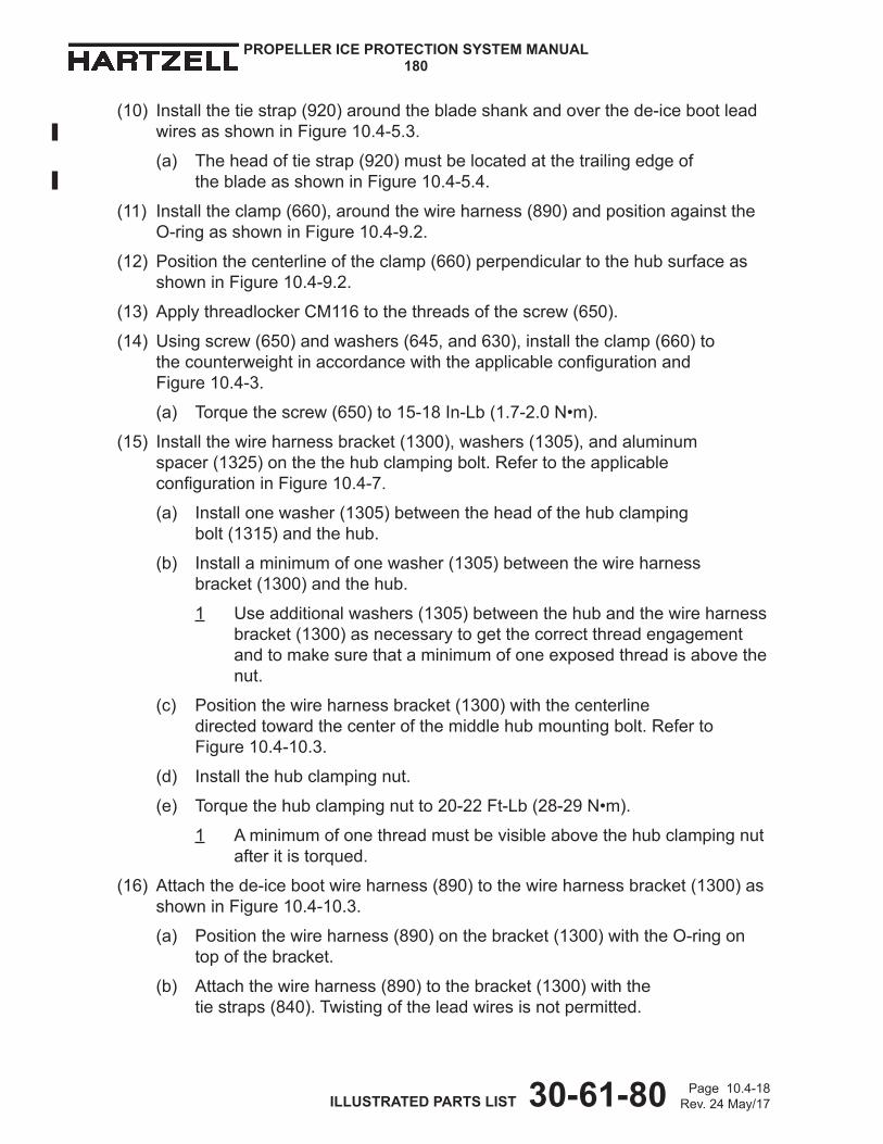
Page10.4-18Rev.24May/17 ILLUSTRATED PARTS LIST 30-61-80
PROPELLER ICE PROTECTION SYSTEM MANUAL180
(10) Installthetiestrap(920)aroundthebladeshankandoverthede-icebootleadwiresasshowninFigure10.4-5.3.
(a) Theheadoftiestrap(920)mustbelocatedatthetrailingedgeof thebladeasshowninFigure10.4-5.4.
(11) Installtheclamp(660),aroundthewireharness(890)andpositionagainsttheO-ringasshowninFigure10.4-9.2.
(12) Positionthecenterlineoftheclamp(660)perpendiculartothehubsurfaceasshowninFigure10.4-9.2.
(13) ApplythreadlockerCM116tothethreadsofthescrew(650).
(14) Usingscrew(650)andwashers(645,and630),installtheclamp(660)to thecounterweightinaccordancewiththeapplicableconfigurationand Figure10.4-3.
(a) Torquethescrew(650)to15-18In-Lb(1.7-2.0N•m).
(15) Installthewireharnessbracket(1300),washers(1305),andaluminum spacer(1325)onthethehubclampingbolt.RefertotheapplicableconfigurationinFigure10.4-7.
(a) Installonewasher(1305)betweentheheadofthehubclamping bolt(1315)andthehub.
(b) Installaminimumofonewasher(1305)betweenthewireharness bracket(1300)andthehub.
1 Useadditionalwashers(1305)betweenthehubandthewireharnessbracket(1300)asnecessarytogetthecorrectthreadengagementandtomakesurethataminimumofoneexposedthreadisabovethenut.
(c) Positionthewireharnessbracket(1300)withthecenterline directedtowardthecenterofthemiddlehubmountingbolt.Referto Figure10.4-10.3.
(d) Installthehubclampingnut.
(e) Torquethehubclampingnutto20-22Ft-Lb(28-29N•m).
1 Aminimumofonethreadmustbevisibleabovethehubclampingnutafteritistorqued.
(16) Attachthede-icebootwireharness(890)tothewireharnessbracket(1300)asshowninFigure10.4-10.3.
(a) Positionthewireharness(890)onthebracket(1300)withtheO-ringontopofthebracket.
(b) Attachthewireharness(890)tothebracket(1300)withthe tiestraps(840).Twistingoftheleadwiresisnotpermitted.

Page10.4-19Rev.24May/17 ILLUSTRATED PARTS LIST 30-61-80
PROPELLER ICE PROTECTION SYSTEM MANUAL180
(17) Attachtheslipringleadwiresandde-icewireharness(890)totheterminal strip(170)inaccordancewiththeapplicableconfigurationinFigure10.4-2.(a) Routethewireharness(890)underbothslipringwiresasshownin
Figure10.4-10.3(b) Tightentheterminalscrewsuntilsnug.
(18) Cyclethepropellerbladesfromreverseangletofeatherangletoverifyproperwireharnessinstallation.
(a) Makesurethewireharnessisnotblockedduringcycling.
H.InstallationInstruction10.4-H
(1) Usingthescrew(220),washers(200and210),tappedeyelet(190),andtheapplicableconfigurationshowninFigure10.4-1,attachtheterminalstrip(170)tothebulkhead.
(a) Torquethescrew(220)to10-12In-Lb(1.2-1.3N•m).
(2) Usingthescrews(1170),attachtheslipring(1140)andthebulkheadtothehubasshowninFigure10.4-6.
(a) Torqueeachscrew(1170)8-10Ft-Lb(10.9-13.5N•m).
(3) Completeaslipringrun-outcheckinaccordancewithHartzellPropellerInc.PropellerIceProtectionSystemComponentMaintenanceManual181 (30-60-81).
(4) Putthepropellerbladesatreversebladeangle.
(5) Ifrequired,pressthespringpin(905)perpendicularlyintotheholeinthecounterweightasshowninFigure10.4-4.
(a) Thespringpin(905)mustextendtoaheightof0.170-0.210inch (4.32-5.33mm).
NOTE: Thecounterweightmayhavebeendrilledforthespringpin(905) ormayhaveanintegral(cast)pininplaceofthespringpin.
(6) Assembletheplugconnectionbetweenthewireharness(890)andthe de-iceboot.
(7) Installthewireharness/de-icebootplugconnectionsinthegrooveinthecounterweightagainstthespringpin(905)orintegralcastpinasshowninFigure10.4-5.2.
Page 10.4-20Rev.24May/17 ILLUSTRATED PARTS LIST 30-61-80
PROPELLER ICE PROTECTION SYSTEM MANUAL180
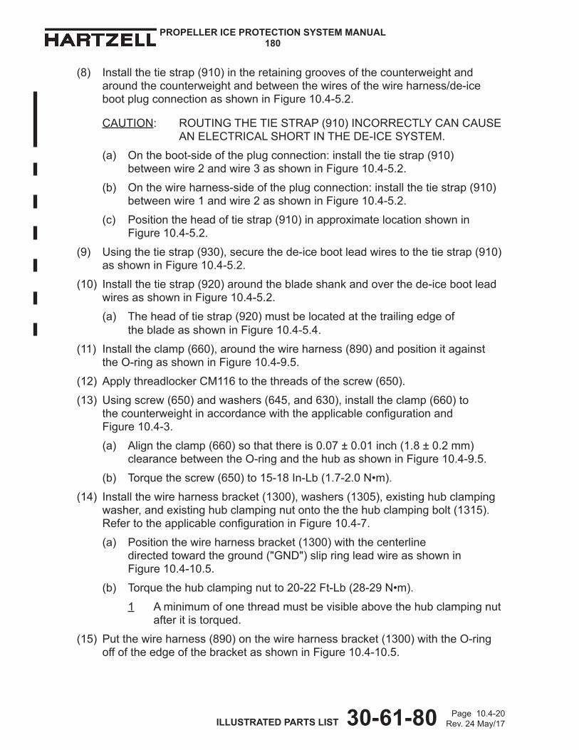
(8) Installthetiestrap(910)intheretaininggroovesofthecounterweightandaroundthecounterweightandbetweenthewiresofthewireharness/de-icebootplugconnectionasshowninFigure10.4-5.2.
CAUTION: ROUTINGTHETIESTRAP(910)INCORRECTLYCANCAUSEANELECTRICALSHORTINTHEDE-ICESYSTEM.
(a) Ontheboot-sideoftheplugconnection:installthetiestrap(910) betweenwire2andwire3asshowninFigure10.4-5.2.
(b) Onthewireharness-sideoftheplugconnection:installthetiestrap(910) betweenwire1andwire2asshowninFigure10.4-5.2.
(c) Positiontheheadoftiestrap(910)inapproximatelocationshownin Figure10.4-5.2.
(9) Usingthetiestrap(930),securethede-icebootleadwirestothetiestrap(910)asshowninFigure10.4-5.2.
(10) Installthetiestrap(920)aroundthebladeshankandoverthede-icebootleadwiresasshowninFigure10.4-5.2.
(a) Theheadoftiestrap(920)mustbelocatedatthetrailingedgeof thebladeasshowninFigure10.4-5.4.
(11) Installtheclamp(660),aroundthewireharness(890)andpositionitagainsttheO-ringasshowninFigure10.4-9.5.
(12) ApplythreadlockerCM116tothethreadsofthescrew(650).
(13) Usingscrew(650)andwashers(645,and630),installtheclamp(660)to thecounterweightinaccordancewiththeapplicableconfigurationand Figure10.4-3.
(a) Aligntheclamp(660)sothatthereis0.07±0.01inch(1.8±0.2mm)clearancebetweentheO-ringandthehubasshowninFigure10.4-9.5.
(b) Torquethescrew(650)to15-18In-Lb(1.7-2.0N•m).
(14) Installthewireharnessbracket(1300),washers(1305),existinghubclampingwasher,andexistinghubclampingnutontothethehubclampingbolt(1315).RefertotheapplicableconfigurationinFigure10.4-7.
(a) Positionthewireharnessbracket(1300)withthecenterline directedtowardtheground("GND")slipringleadwireasshownin Figure10.4-10.5.
(b) Torquethehubclampingnutto20-22Ft-Lb(28-29N•m).
1 Aminimumofonethreadmustbevisibleabovethehubclampingnutafteritistorqued.
(15) Putthewireharness(890)onthewireharnessbracket(1300)withtheO-ringoffoftheedgeofthebracketasshowninFigure10.4-10.5.

Page 10.4-20.1Rev.24May/17 ILLUSTRATED PARTS LIST 30-61-80
PROPELLER ICE PROTECTION SYSTEM MANUAL180
CAUTION: TWISTINGOFTHELEADWIRESBETWEENTHE CLAMP(660)ANDTHEWIREHARNESSBRACKET(1300) ISNOTPERMITTED.
(a) Attachthewireharness(890)tothewireharnessbracket(1300) withtwotiestraps(840)asshowninFigure10.4-10.5.
(16) Routethewireharness(890)undertheinboard("INBD")slipringleadwireandovertheoutboard("OUTBD")andground("GND")slipringleadwiresasshowninFigure10.4-10.5.
(17) Attachtheleadwiresfromtheslipring(1140)andtheleadwiresfromthewire harness(890)totheterminalstrip(170)inaccordancewiththeapplicableconfigurationinFigure10.4-2 andFigure 10.4-10.5.
(a) Usingonetiestrap(930),attachtheleadwiresfromthewire harness(890)totheground("GND")slipringleadwireasshownin Figure10.4-10.5.
(b) Tightentheterminalstripscrewsuntilsnug.
(18) Cyclethepropellerbladesfromreverseangletofeatherangletoverifyproperwireharnessinstallation.Makesurethewireharnessisnotblockedduringcycling.
Page 10.4-20.2Rev.24May/17 ILLUSTRATED PARTS LIST 30-61-80
PROPELLER ICE PROTECTION SYSTEM MANUAL180
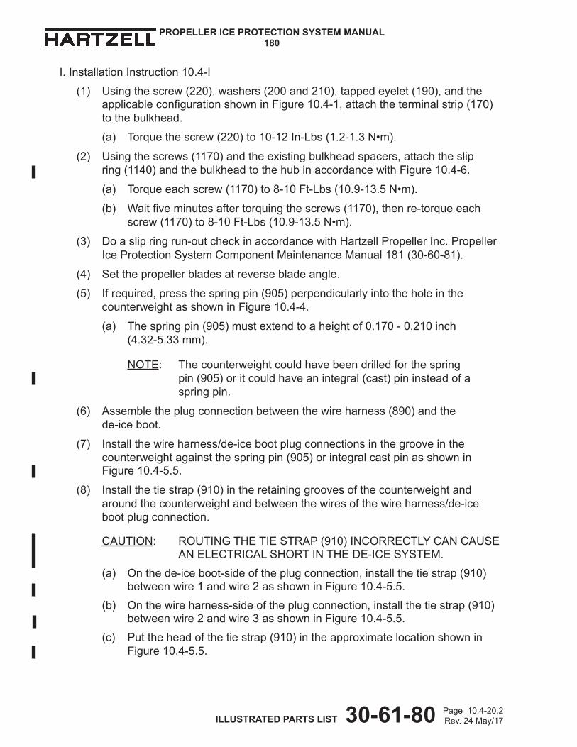
I.InstallationInstruction10.4-I
(1) Usingthescrew(220),washers(200and210),tappedeyelet(190),andtheapplicableconfigurationshowninFigure10.4-1,attachtheterminalstrip(170)tothebulkhead.
(a) Torquethescrew(220)to10-12In-Lbs(1.2-1.3N•m).
(2) Usingthescrews(1170)andtheexistingbulkheadspacers,attachtheslip ring(1140)andthebulkheadtothehubinaccordancewithFigure10.4-6.
(a) Torqueeachscrew(1170)to8-10Ft-Lbs(10.9-13.5N•m).
(b) Waitfiveminutesaftertorquingthescrews(1170),thenre-torqueeachscrew(1170)to8-10Ft-Lbs(10.9-13.5N•m).
(3) Doaslipringrun-outcheckinaccordancewithHartzellPropellerInc.PropellerIceProtectionSystemComponentMaintenanceManual181(30-60-81).
(4) Setthepropellerbladesatreversebladeangle.
(5) Ifrequired,pressthespringpin(905)perpendicularlyintotheholeinthecounterweightasshowninFigure10.4-4.
(a) Thespringpin(905)mustextendtoaheightof0.170-0.210inch (4.32-5.33mm).
NOTE: Thecounterweightcouldhavebeendrilledforthespring pin (905)oritcouldhaveanintegral(cast)pininsteadofaspringpin.
(6) Assembletheplugconnectionbetweenthewireharness(890)andthe de-iceboot.
(7) Installthewireharness/de-icebootplugconnectionsinthegrooveinthecounterweightagainstthespringpin(905)orintegralcastpinasshowninFigure10.4-5.5.
(8) Installthetiestrap(910)intheretaininggroovesofthecounterweightandaroundthecounterweightandbetweenthewiresofthewireharness/de-icebootplugconnection.
CAUTION: ROUTINGTHETIESTRAP(910)INCORRECTLYCANCAUSEANELECTRICALSHORTINTHEDE-ICESYSTEM.
(a) Onthede-iceboot-sideoftheplugconnection,installthetiestrap(910) betweenwire1andwire2asshowninFigure10.4-5.5.
(b) Onthewireharness-sideoftheplugconnection,installthetiestrap(910) betweenwire2andwire3asshowninFigure10.4-5.5.
(c) Puttheheadofthetiestrap(910)intheapproximatelocationshownin Figure10.4-5.5.

Page 10.4-20.3Rev.24May/17 ILLUSTRATED PARTS LIST 30-61-80
PROPELLER ICE PROTECTION SYSTEM MANUAL180
(9) Usingthetiestrap(930),attachthede-icebootleadwirestothetiestrap(910)asshowninFigure10.4-5.5.
(10) Installthetiestrap(920)aroundthebladeshankandoverthede-icebootleadwiresasshowninFigure10.4-5.5.
(a) Theheadoftiestrap(920)mustbelocatedatthetrailingedgeof thebladeasshowninFigure10.4-5.5.
(11) Installtheclamp(660),aroundthewireharness(890)andputitagainsttheO-ringasshowninFigure10.4-9.4.
(12) Installtheclamp(660)ontothecounterweight.
(a) Putthecenterlineoftheclamp(660)paralleltothehubsurfaceasshowninFigure10.4-9.4.
(b) ApplythreadlockerCM116tothethreadsofthescrew(650).
(c) Usingscrew(650)andwashers(645and630),installtheclamp(660) tothecounterweightinaccordancewiththeapplicableconfigurationshowninFigure10.4-3.
1 Torquethescrew(650)to15-18In-Lbs(1.7-2.0N•m).
(13) Installthewashers(1305),wireharnessbracket(1300),existinghubclampingwasher,andexistinghubclampingnutontothethehubclampingbolt(1315).RefertotheapplicableconfigurationinFigure10.4-7.
(a) Putthelongedgeofwireharnessbracket(1300) paralleltothe bladecenterlineasshowninFigure10.4-10.6.
(b) Torquethehubclampingnutto20-22Ft-Lbs(27.2-29.8N•m).
(14) Attachthewireharness(890)tothewireharnessbracket(1300)asshowninFigure10.4-10.6.
(a) Positionthewireharness(890)withtheO-ringontopofthe bracket(1300)asshowninFigure10.4-8.1.
(b) Attachthewireharness(890)tothebracket(1300)withtwo tiestraps(840).Twistingoftheleadwiresisnotpermitted.
(c) Positiontheheadsofthetiestraps(840)asshowninFigure10.4-10.6.
(15) Installtheslipringleadwiresandde-icewireharness(890)totheterminal strip(170)inaccordancewithFigure10.4-1and10.4-2.
(16) Tightentheterminalscrewsuntilsnug.
(17) Cyclethepropellerbladesfromreverseangletofeatherangletomakesureof properwireharnessinstallation.Makesurethewireharnessisnotblockedduringcycling.

Page 10.4-20.4Rev.24May/17 ILLUSTRATED PARTS LIST 30-61-80
PROPELLER ICE PROTECTION SYSTEM MANUAL180
(Thispageisintentinallyblank.)

Page 10.4-33Rev. 20 Dec/15 ILLUSTRATED PARTS LIST 30-61-80
PROPELLER ICE PROTECTION SYSTEM MANUAL180
Wire Harness to Blade Shank/Counterweight Figure 10.4-5.1
910
De-iceBoot
930
890
De-iceBootLeadWires
930
890 910
ShownwithoutTieStrap910
905,IfRequired
Page 10.4-34Rev.24May/17 ILLUSTRATED PARTS LIST 30-61-80
PROPELLER ICE PROTECTION SYSTEM MANUAL180
31
32
1
31
32
1
2
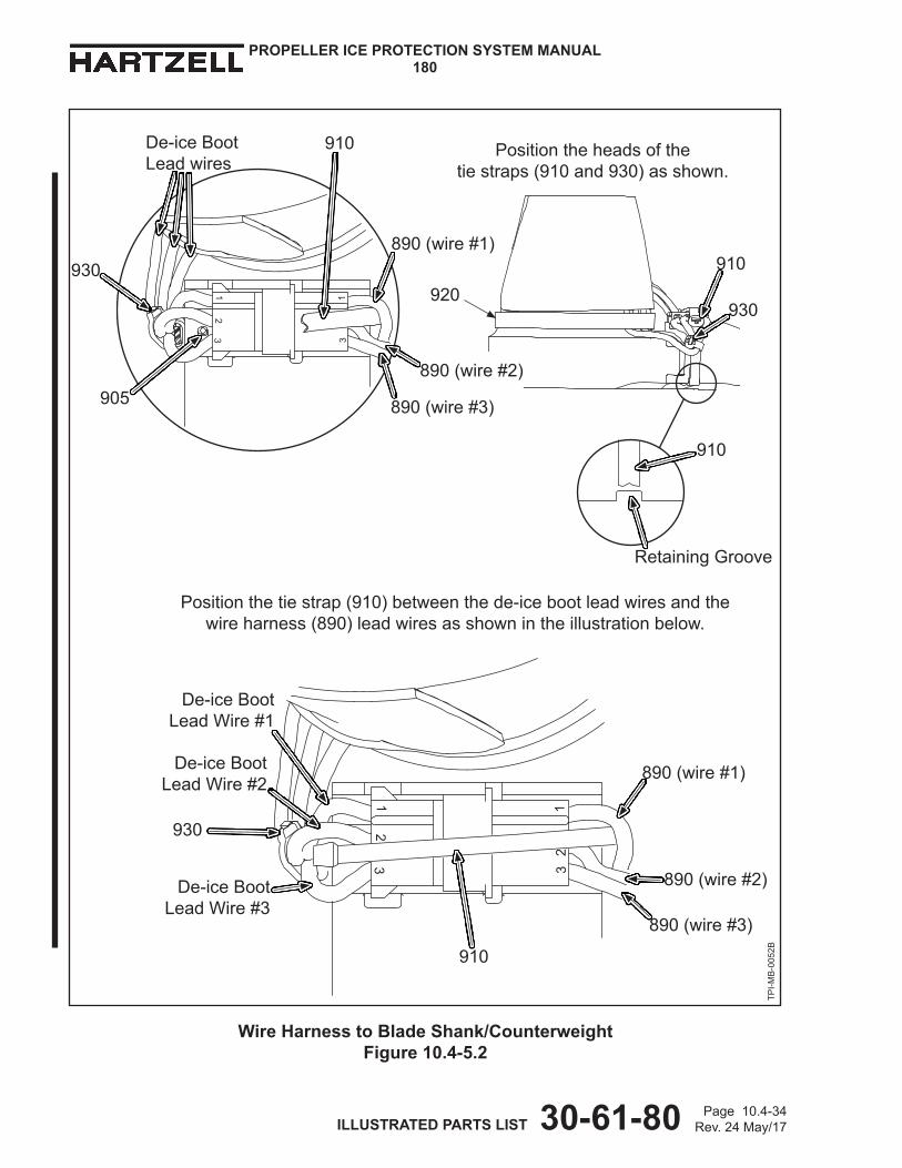
Positiontheheadsofthe tiestraps(910and930)asshown.
Wire Harness to Blade Shank/Counterweight Figure 10.4-5.2
TPI-M
B-0052B
Positionthetiestrap(910)betweenthede-icebootleadwiresandthewireharness(890)leadwiresasshownintheillustrationbelow.
905
930
De-iceBootLeadwires
910
890(wire#1)
890(wire#3)
890(wire#2)
910
930
910
RetainingGroove
De-iceBootLeadWire#1
De-iceBootLeadWire#2
930
De-iceBootLeadWire#3
910
890(wire#1)
890(wire#3)
890(wire#2)
920

Page 10.4-35Rev.24May/17 ILLUSTRATED PARTS LIST 30-61-80
PROPELLER ICE PROTECTION SYSTEM MANUAL180
TPI-M
B-0055
12
3
23
1
910
910
905
930
De-iceBoot LeadWires
910
930
Positiontheheadsofthe tiestraps(910,930)asshown
920
Wire Harness to Blade Shank/Counterweight Figure 10.4-5.3
Positionthetiestrap(910)betweenthede-icebootleadwiresandthewireharness(890)leadwiresasshownintheillustrationbelow.
890(wire#1)
890(wire#2)
De-iceBootLeadWire#1De-iceBoot
LeadWire#2
930 890(wire#1)
890(wire#2)
Page10.4-36Rev.24May/17 ILLUSTRATED PARTS LIST 30-61-80
PROPELLER ICE PROTECTION SYSTEM MANUAL180
TI-180100155
Positiontheheadoftiestrap(920)asshownonthetrailingedgeoftheblade.
920
Wire Harness to Blade ShankFigure 10.4-5.4
TI-180100155

Page10.4-37Rev.24May/17 ILLUSTRATED PARTS LIST 30-61-80
PROPELLER ICE PROTECTION SYSTEM MANUAL180
3
12
3
13
21
2
3
1
Wire Harness-to-Blade Shank/Counterweight Figure 10.4-5.5
905
930
De-iceBoot PlugConnector
910
910
Positiontheheadsofthe tiestraps(910,920,930)asshown
RetainingGroove
910
TPI-M
B-0186
WireHarness(890) PlugConnector
920
920
De-iceBootLeadWire#1
De-iceBootLeadWire#2
De-iceBootLeadWire#3
890(wire#1)
890(wire#2)
890(wire#3)

Page10.4-38Rev.24May/17 ILLUSTRATED PARTS LIST 30-61-80
PROPELLER ICE PROTECTION SYSTEM MANUAL180
Slip Ring MountingFigure 10.4-6
Hub
ExistingBulkheadSpacer (RefertoNOTE)
1170 1140 Bulkhead
TPI-M
B-0204,TPI-M
B-0223NOTE: Thebulkheadspacerisaspinnermountingcomponent
andisapplicationspecific.RefertoHartzellPropellerInc.ApplicationGuideManual159(61-02-59).
Hub
1170 1140 Bulkhead
Typical Slip Ring Installation (without bulkhead spacer)
Typical Slip Ring Installation (with bulkhead spacer)

Page10.4-63Rev. 20 Dec/15 ILLUSTRATED PARTS LIST 30-61-80
PROPELLER ICE PROTECTION SYSTEM MANUAL180
FIG./ITEM PART DESCRIPTION UPA O/H NUMBER NUMBER
- ITEM NOT ILLUSTRATED
De-ice Kits for Lightweight Turbine Propellers with Composite Blades
104264 PROPELLER DE-ICE KIT INSTALLATION INSTRUCTION 10.4-C
TERMINAL STRIP HARDWARE: BULKHEAD MOUNTED10.4-1 CONFIGURATION GT10.4-2 TYPICAL 3-WIRE CONFIGURATION 170 1H1150-2 •TERMINALSTRIP 3 190 2H1365 •TAPPEDEYELET 6 Y 200 B-3854-41 •WASHER,LOCK 9 Y 220 B-6637-34 •SCREW,6-32,FILLISTERHEAD,CRES 6 Y 240 2H1852-2 •TERMINALSTRIPSPACER 3
10.4-1.1 TERMINAL STRIP HARDWARE: COUNTERWEIGHT MOUNTED10.4-2.1 CONFIGURATION ATC10.4-9 TYPICAL 3-WIRE CONFIGURATION 310 1H1150-2 •TERMINALSTRIP 3 320 B-6631-231 •SCREW,6-32,FILLISTERHEAD,CRES 6 Y 330 B-3854-41 •WASHER,LOCK 9 Y 340 2H1852-2 •TERMINALSTRIPSPACER 3
10.4-3 LOOP CLAMP TO COUNTERWEIGHT10.4-9 CONFIGURATION ACC 645 B-3855-31 •WASHER,LOCK,EXTERNALTOOTH 3 Y 650 B-3856-246 •SCREW,8-32,FILLISTERHEAD,CRES 3 Y 655 B-3854-42 •WASHER,LOCK 3 Y 660 B-3853-F5 •CLAMP,LOOP,PLASTIC 3 Y 665 B-3837-N832 •WASHER,CORROSIONRESISTANT 3 Y 670 B-6583-0437 •SPRINGPIN,3/32 3 Y
10.4-11 890 3H2526-2 •WIREHARNESS 3 Y 895 3H1452 •WIREHARNESS,SLIPRING 3 Y 930 B-3852-6-0 •STRAP,TIEDOWN,PLASTIC 2 Y
10.4-8 DE-ICE WIRE HARNESS BRACKET10.4-7 CONFIGURATION B 840 B-3852-1-0 •STRAP,TIEDOWN,PLASTIC 6 Y 1300 B-6265 •BRACKET,WIREHARNESS 3 1305 B-3834-0632 •WASHER 6 Y 1830 B-3599 •NUT,3/8-24,HEX,SELF-LOCKING 3 Y
Page10.4-64Rev.24May/17 ILLUSTRATED PARTS LIST 30-61-80
PROPELLER ICE PROTECTION SYSTEM MANUAL180
FIG./ITEM PART DESCRIPTION UPA O/H NUMBER NUMBER
- ITEM NOT ILLUSTRATEDDe-ice Kits for Lightweight Turbine Propellers with Composite Blades
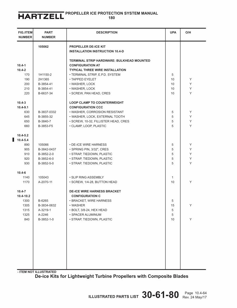
105062 PROPELLER DE-ICE KIT INSTALLATION INSTRUCTION 10.4-D
TERMINAL STRIP HARDWARE: BULKHEAD MOUNTED10.4-1 CONFIGURATION AT10.4-2 TYPICAL THREE WIRE INSTALLATION 170 1H1150-2 •TERMINALSTRIP,E.P.D.SYSTEM 5 190 2H1365 •TAPPEDEYELET 10 Y 200 B-3854-41 •WASHER,LOCK 10 Y 210 B-3854-41 •WASHER,LOCK 10 Y 220 B-6637-34 •SCREW,PANHEAD,CRES 10 Y
10.4-3 LOOP CLAMP TO COUNTERWEIGHT10.4-9.1 CONFIGURATION CCC 630 B-3837-0332 •WASHER,CORROSIONRESISTANT 5 Y 645 B-3855-32 •WASHER,LOCK,EXTERNALTOOTH 5 Y 650 B-3840-7 •SCREW,10-32,FILLISTERHEAD,CRES 5 Y 660 B-3853-F5 •CLAMP,LOOP,PLASTIC 5 Y
10.4-5.210.4-5.4 890 105066 •DE-ICEWIREHARNESS 5 Y 905 B-3842-0437 •SPRINGPIN,3/32",CRES 5 Y 910 B-3852-2-0 •STRAP,TIEDOWN,PLASTIC 5 Y 920 B-3852-6-0 •STRAP,TIEDOWN,PLASTIC 5 Y 930 B-3852-5-0 •STRAP,TIEDOWN,PLASTIC 5 Y
10.4-6 1140 105043 •SLIPRINGASSEMBLY 1 1170 A-2070-11 •SCREW,1/4-28,BUTTONHEAD 10 Y
10.4-7 DE-ICE WIRE HARNESS BRACKET10.4-10.2 CONFIGURATION C 1300 B-6265 •BRACKET,WIREHARNESS 5 1305 B-3834-0632 •WASHER 15 Y 1315 A-3219-1 •BOLT,3/8-24,HEXHEAD 5 1325 A-2246 •SPACERALUMINUM 5 840 B-3852-1-0 •STRAP,TIEDOWN,PLASTIC 10 Y

Page10.4-65Rev.24May/17 ILLUSTRATED PARTS LIST 30-61-80
PROPELLER ICE PROTECTION SYSTEM MANUAL180
FIG./ITEM PART DESCRIPTION UPA O/H NUMBER NUMBER
- ITEM NOT ILLUSTRATED
De-ice Kits for Lightweight Turbine Propellers with Composite Blades
105551 PROPELLER DE-ICE KIT (ONE PROP) INSTALLATION INSTRUCTION 10.4-E
TERMINAL STRIP HARDWARE: BULKHEAD MOUNTED10.4-1 CONFIGURATION AT10.4-2 TYPICAL THREE WIRE INSTALLATION 170 1H1150-2 •TERMINALSTRIP,E.P.D.SYSTEM 5 190 2H1365 •TAPPEDEYELET 10 Y 200 B-3854-41 •WASHER,LOCK 10 Y 210 B-3854-41 •WASHER,LOCK 10 Y 220 B-6637-34 •SCREW,PANHEAD,CRES 10 Y
10.4-3 LOOP CLAMP TO COUNTERWEIGHT10.4-9.2 CONFIGURATION CCC 630 B-3837-0332 •WASHER,CORROSIONRESISTANT 5 Y 645 B-3855-32 •WASHER,LOCK,EXTERNALTOOTH 5 Y 650 B-3840-() •SCREW,10-32,FILLISTERHEAD,CRES 5 Y 660 B-3853-F5 •CLAMP,LOOP,PLASTIC 5 Y
10.4-5.210.4-5.4 890 105555 •DE-ICEWIREHARNESS 5 Y 905 B-3842-0437 •SPRINGPIN,3/32",CRES 5 Y 910 B-3852-2-0 •STRAP,TIEDOWN,PLASTIC 5 Y 920 B-3852-6-0 •STRAP,TIEDOWN,PLASTIC 5 Y 930 B-3852-5-0 •STRAP,TIEDOWN,PLASTIC 5 Y
10.4-6 1140 105043 •SLIPRINGASSEMBLY 1 1170 A-2070-11 •SCREW,1/4-28,BUTTONHEAD 10 Y
10.4-7 DE-ICE WIRE HARNESS BRACKET 10.4-10.3 CONFIGURATION C 1300 105558 •BRACKET,WIREHARNESS 5 1305 B-3834-0632 •WASHER 15 Y 1315 A-3219-1 •BOLT,3/8-24,HEXHEAD 5 1325 A-2246 •SPACERALUMINUM 5 840 B-3852-1-0 •STRAP,TIEDOWN,PLASTIC 10 Y

Page10.4-66Rev.24May/17 ILLUSTRATED PARTS LIST 30-61-80
PROPELLER ICE PROTECTION SYSTEM MANUAL180
FIG./ITEM PART DESCRIPTION UPA O/H NUMBER NUMBER
- ITEM NOT ILLUSTRATEDDe-ice Kits for Lightweight Turbine Propellers with Composite Blades
105934 PROPELLER DE-ICE KIT (ONE PROP) INSTALLATION INSTRUCTION 10.4-F
TERMINAL STRIP HARDWARE: BULKHEAD MOUNTED10.4-1 CONFIGURATION AT10.4-2 ALTERNATE THREE WIRE INSTALLATION 170 1H1150-2 •TERMINALSTRIP,E.P.D.SYSTEM 5 190 2H1365 •TAPPEDEYELET 10 Y 200 B-3854-41 •WASHER,LOCK 10 Y 210 B-3854-41 •WASHER,LOCK 10 Y 220 B-6637-34 •SCREW,PANHEAD,CRES 10 Y
10.4-3 LOOP CLAMP TO BLADE SHANK10.4-9.3 CONFIGURATION CCC 630 B-3837-0332 •WASHER,CORROSIONRESISTANT 5 645 B-3855-32 •WASHER,LOCK,EXTERNALTOOTH 5 Y 650 B-3840-7 •SCREW,10-32,FILLISTERHEAD 5 Y 660 B-3853-F5 •CLAMP,LOOP,PLASTIC 5 Y
10.4-5.2 10.4-5.4 890 105555 •DE-ICEWIREHARNESS 5 Y 905 B-3842-0437 •SPRINGPIN,3/32",CRES 5 Y 910 B-3852-2-0 •STRAP,TIEDOWN,PLASTIC 5 Y 920 B-3852-6-0 •STRAP,TIEDOWN,PLASTIC 5 Y 930 B-3852-5-0 •STRAP,TIEDOWN,PLASTIC 5 Y
10.4-6 1140 105882 •SLIPRINGASSEMBLY 1 1170 A-2070-8 •SCREW,1/4-28,BUTTONHEAD 10 Y
10.4-7 DE-ICE WIRE HARNESS BRACKET 10.4-10.4 CONFIGURATION D 1300 B-6265 •BRACKET,WIREHARNESS 5 1305 B-3834-0632 •WASHER 20 Y 1315 A-3219-1 •BOLT,3/8-24,HEXHEAD 5 1325 A-2246 •SPACERALUMINUM 5 840 B-3852-1-0 •STRAP,TIEDOWN,PLASTIC 10 Y

Page10.4-67Rev.24May/17 ILLUSTRATED PARTS LIST 30-61-80
PROPELLER ICE PROTECTION SYSTEM MANUAL180
FIG./ITEM PART DESCRIPTION UPA O/H NUMBER NUMBER
- ITEM NOT ILLUSTRATED
De-ice Kits for Lightweight Turbine Propellers with Composite Blades
106049 PROPELLER DE-ICE KIT (ONE PROP) INSTALLATION INSTRUCTION 10.4-G
TERMINAL STRIP HARDWARE: BULKHEAD MOUNTED10.4-1 CONFIGURATION AT (TERMINAL STRIP ORIENTATION B)10.4-2 TYPICAL TWO WIRE INSTALLATION 170 1H1150-3 •TERMINALSTRIP,E.P.D.SYSTEM 5 190 2H1365 •TAPPEDEYELET 10 Y 200 B-3854-41 •WASHER,LOCK 10 Y 210 B-3854-41 •WASHER,LOCK 10 Y 220 B-6637-34 •SCREW,PANHEAD,CRES 10 Y
10.4-3 LOOP CLAMP TO BLADE SHANK10.4-9.2 CONFIGURATION CCC 630 B-3837-0332 •WASHER,CORROSIONRESISTANT 5 645 B-3855-32 •WASHER,LOCK,EXTERNALTOOTH 5 Y 650 B-3840-7 •SCREW,10-32,FILLISTERHEAD 5 Y 660 B-3853-F5 •CLAMP,LOOP,PLASTIC 5 Y
10.4-5.3 10.4-5.4 890 106051 •DE-ICEWIREHARNESS 5 Y 905 B-3842-0437 •SPRINGPIN,3/32",CRES 5 Y 910 B-3852-2-0 •STRAP,TIEDOWN,PLASTIC 5 Y 920 B-3852-6-0 •STRAP,TIEDOWN,PLASTIC 5 Y 930 B-3852-5-0 •STRAP,TIEDOWN,PLASTIC 5 Y
10.4-6 1140 106935 •SLIPRINGASSEMBLY 1 1170 A-2070-10 •SCREW,1/4-28,BUTTONHEAD 10 Y
10.4-7 DE-ICE WIRE HARNESS BRACKET 10.4-10.3 CONFIGURATION D 1300 105558 •BRACKET,WIREHARNESS 5 1305 B-3834-0632 •WASHER 20 Y 1315 A-3219-1 •BOLT,3/8-24,HEXHEAD 5 1325 A-2246 •SPACERALUMINUM 5 840 B-3852-1-0 •STRAP,TIEDOWN,PLASTIC 10 Y

Page10.4-68Rev.24May/17 ILLUSTRATED PARTS LIST 30-61-80
PROPELLER ICE PROTECTION SYSTEM MANUAL180
FIG./ITEM PART DESCRIPTION UPA O/H NUMBER NUMBER
- ITEM NOT ILLUSTRATEDDe-ice Kits for Lightweight Turbine Propellers with Composite Blades
106285 PROPELLER DE-ICE KIT (ONE PROP) INSTALLATION INSTRUCTION 10.4-H
TERMINAL STRIP HARDWARE: BULKHEAD MOUNTED10.4-1 CONFIGURATION AT10.4-2 TYPICAL THREE WIRE INSTALLATION 170 1H1150-2 •TERMINALSTRIP 5 190 2H1365 •TAPPEDEYELET 10 Y 200 B-3854-41 •WASHER,LOCK 10 Y 210 B-3854-41 •WASHER,LOCK 10 Y 220 B-6637-34 •SCREW,PANHEAD,CRES 10 Y
10.4-3 LOOP CLAMP TO BLADE SHANK10.4-9.5 CONFIGURATION CCC 630 B-3837-0332 •WASHER,CORROSIONRESISTANT 5 645 B-3855-32 •WASHER,LOCK,EXTERNALTOOTH 5 Y 650 B-3840-7 •SCREW,10-32,FILLISTERHEAD 5 Y 660 B-3853-F5 •CLAMP,LOOP,PLASTIC 5 Y
10.4-5.2 10.4-5.4 890 105066 •WIREHARNESS 5 Y REPLACEDBYITEM890A,PREHC-SB-30-375 890A 105555 •WIREHARNESS 5 Y REPLACESITEM890,POSTHC-SB-30-375 905 B-3842-0437 •SPRINGPIN,3/32",CRES 5 Y 910 B-3852-2-0 •STRAP,TIEDOWN,PLASTIC 5 Y 920 B-3852-6-0 •STRAP,TIEDOWN,PLASTIC 5 Y 930 B-3852-5-0 •STRAP,TIEDOWN,PLASTIC 10 Y
10.4-6 1140 105925 •SLIPRINGASSEMBLY 1 1170 A-2070-6 •SCREW,1/4-28,BUTTONHEAD 10 Y
10.4-7 DE-ICE WIRE HARNESS BRACKET 10.4-10.5 CONFIGURATION E 1300 105558 •BRACKET,WIREHARNESS 5 1305 B-3834-0663 •WASHER 5 Y 1315 102691 •BOLT,3/8-24,HEXHEAD 5 840 B-3852-1-0 •STRAP,TIEDOWN,PLASTIC 10 Y

Page10.4-69Rev.24May/17 ILLUSTRATED PARTS LIST 30-61-80
PROPELLER ICE PROTECTION SYSTEM MANUAL180
FIG./ITEM PART DESCRIPTION UPA O/H NUMBER NUMBER
- ITEM NOT ILLUSTRATED
De-ice Kits for Lightweight Turbine Propellers with Composite Blades
106783 PROPELLER DE-ICE KIT (ONE PROP) INSTALLATION INSTRUCTION 10.4-I
TERMINAL STRIP HARDWARE: BULKHEAD MOUNTED10.4-1 CONFIGURATION AT10.4-2 TYPICAL THREE WIRE INSTALLATION 170 1H1150-2 •TERMINALSTRIP 4 190 2H1365 •TAPPEDEYELET 8 Y 200 B-3854-41 •WASHER,LOCK 8 Y 210 B-3854-41 •WASHER,LOCK 8 Y 220 B-6637-34 •SCREW,PANHEAD,CRES 8 Y
10.4-3 LOOP CLAMP TO BLADE SHANK10.4-9.4 CONFIGURATION CCC 630 B-3837-0332 •WASHER,CORROSIONRESISTANT 4 645 B-3855-32 •WASHER,LOCK,EXTERNALTOOTH 4 Y 650 B-3840-7 •SCREW,10-32,FILLISTERHEAD 4 Y 660 B-3853-F5 •CLAMP,LOOP,NYLON 4 Y 10.4-410.4-5.5 890 106615 •WIREHARNESS 4 Y 905 B-3842-0437 •SPRINGPIN,3/32",CRES 4 Y 910 B-3852-2-0 •STRAP,TIEDOWN,PLASTIC 4 Y 920 B-3852-6-0 •STRAP,TIEDOWN,PLASTIC 4 Y 930 B-3852-5-0 •STRAP,TIEDOWN,PLASTIC 4 Y
10.4-6 1140 106556 •SLIPRINGASSEMBLY 1 1170 A-2070-11 •SCREW,1/4-28,BUTTONHEAD 8 Y
10.4-7 DE-ICE WIRE HARNESS BRACKET 10.4-10.6 CONFIGURATION B 1300 B-6265L •BRACKET,WIREHARNESS,LH 4 1305 B-3834-0663 •WASHER 8 Y 1315 102691 •BOLT,3/8-24,HEXHEAD 4 840 B-3852-1-0 •STRAP,TIEDOWN,PLASTIC 8 Y

Page10.4-70Rev.24May/17 ILLUSTRATED PARTS LIST 30-61-80
PROPELLER ICE PROTECTION SYSTEM MANUAL180
FIG./ITEM PART DESCRIPTION UPA O/H NUMBER NUMBER
- ITEM NOT ILLUSTRATEDDe-ice Kits for Lightweight Turbine Propellers with Composite Blades
106818 PROPELLER DE-ICE KIT (ONE PROP) INSTALLATION INSTRUCTION 10.4-G
TERMINAL STRIP HARDWARE: BULKHEAD MOUNTED10.4-1 CONFIGURATION AT (TERMINAL STRIP ORIENTATION B)10.4-2 TYPICAL TWO WIRE INSTALLATION 170 1H1150-3 •TERMINALSTRIP,E.P.D.SYSTEM 5 190 2H1365 •TAPPEDEYELET 10 Y 200 B-3854-41 •WASHER,LOCK 10 Y 210 B-3854-41 •WASHER,LOCK 10 Y 220 B-6637-34 •SCREW,PANHEAD,CRES 10 Y
10.4-3 LOOP CLAMP TO BLADE SHANK10.4-9.2 CONFIGURATION CCC 630 B-3837-0332 •WASHER,CORROSIONRESISTANT 5 645 B-3855-32 •WASHER,LOCK,EXTERNALTOOTH 5 Y 650 B-3840-7 •SCREW,10-32,FILLISTERHEAD 5 Y 660 B-3853-F5 •CLAMP,LOOP,PLASTIC 5 Y
10.4-5.3 10.4-5.4 890 106051 •DE-ICEWIREHARNESS 5 Y 905 B-3842-0437 •SPRINGPIN,3/32",CRES 5 Y 910 B-3852-2-0 •STRAP,TIEDOWN,PLASTIC 5 Y 920 B-3852-6-0 •STRAP,TIEDOWN,PLASTIC 5 Y 930 B-3852-5-0 •STRAP,TIEDOWN,PLASTIC 5 Y
10.4-6 1140 106935 •SLIPRINGASSEMBLY 1 1170 A-2070-9 •SCREW,1/4-28,BUTTONHEAD 10 Y
10.4-7 DE-ICE WIRE HARNESS BRACKET 10.4-10.3 CONFIGURATION D 1300 105558 •BRACKET,WIREHARNESS 5 1305 B-3834-0632 •WASHER 20 Y 1315 A-3219-1 •BOLT,3/8-24,HEXHEAD 5 1325 A-2246 •SPACERALUMINUM 5 840 B-3852-1-0 •STRAP,TIEDOWN,PLASTIC 10 Y

Page 10.12-3Rev. 22 Nov/16 ILLUSTRATED PARTS LIST 30-61-80
PROPELLER ICE PROTECTION SYSTEM MANUAL180
Airframe Kits and Approved Installation Instructions Table 10.12-1
Kit Part Number Vendor Approved InstallationInstructions
7931-5E2647-2 Goodrich Corporation 5E2647 Rev. H7931-5E2682-2 Goodrich Corporation 5E2682 Rev. D7931-5E2707-2 Goodrich Corporation 5E2707 Rev. D7931-5E2715-2 Goodrich Corporation 5E2715 Rev. J7931-5E2793-4 Hartzell Propeller Inc. 5E2793 Rev. C7931-65-600-2 Goodrich Corporation 7E1784 Rev. D7931-65-600-5 Goodrich Corporation 7E1784 Rev. D7931-67-195 Goodrich Corporation 7E1431 Rev. L
7931-67-750-2 Goodrich Corporation 7E1761 Rev. C7931-67-805-2 Goodrich Corporation 7E1772 Rev. B7931-67-815-2 Goodrich Corporation 7E1776 Rev. F7931-67-825-2 Goodrich Corporation 7E1778 Rev. G7931-67-825-3 Goodrich Corporation 7E1778 Rev. G7931-67-830-2 Goodrich Corporation Per Aircraft TC Holder's ICA7931-67-931-2 Goodrich Corporation 5E2620 Rev. E7931-67-940-2 Goodrich Corporation 5E2662 Rev. H7931-67-940-3 Goodrich Corporation 5E2662 Rev. H7931-67-941-2 Goodrich Corporation 5E2663 Rev. L7931-67-942-2 Goodrich Corporation 5E2664 Rev. C
102014-2 Hartzell Propeller Inc. Per Malibu Power and Propeller, Int'l Instructions
102014-3 Hartzell Propeller Inc. Per Malibu Power and Propeller, Int'l Instructions
102014-4 Hartzell Propeller Inc. Per Malibu Power and Propeller, Int'l Instructions
102014-5 Hartzell Propeller Inc. Per Airframe Manufacturer's Instructions
102195-2 Hartzell Propeller Inc. Per Airframe Manufacturer's Instructions
102544-2 Hartzell Propeller Inc. Installation Instruction 10.12-B, Figures 10.12, 10.12-5
102544-3 Hartzell Propeller Inc. Installation Instruction 10.12-A, Figures 10.12 and 10.12-2, 10.12-5
102600-2 Hartzell Propeller Inc. Installation Instruction 10.12-E, Figures 10.12-6 and
10.12-7102960-2 Hartzell Propeller Inc. Installation Instructions 10.12-C,
Figures 10.12-4102998-2 Hartzell Propeller Inc. Installation Instruction 10.12-D,
Figures 10.12-1, 10.12-3, and 10.12-5

Page 10.12-4Rev. 24 May/17 ILLUSTRATED PARTS LIST 30-61-80
PROPELLER ICE PROTECTION SYSTEM MANUAL180
Kit Part Number Vendor Approved InstallationInstructions
102998-3 Hartzell Propeller Inc. Figure 10.8-4103294-4 Hartzell Propeller Inc. Installation Instruction 10.12-F,
Figures 10.12-8 and 10.12-9103294-5 Hartzell Propeller Inc. Installation Instruction 10.12-F,
Figures 10.12-8 and 10.12-9103307 Hartzell Propeller Inc. Installation Instruction 10.12-D,
Figures 10.12-1, 10.12-3, and 10.12-5103308 Hartzell Propeller Inc. Figure 10.8-4103643 Hartzell Propeller Inc. Per Aircraft TC Holder's ICA103644 Hartzell Propeller Inc. Per Aircraft TC or STC Holder's ICA103652 Hartzell Propeller Inc. Installation Instruction 10.12-G,
Figures 10.12-10104009 Hartzell Propeller Inc. Per Aircraft TC or STC Holder's ICA104128 Hartzell Propeller Inc. Per Aircraft TC or STC Holder's ICA104181 Hartzell Propeller Inc. Installation Instruction 10.12-H,
Figures 10.12-1 and 10.12-5104252 Hartzell Propeller Inc. Per Aircraft TC Holder's ICA104265 Hartzell Propeller Inc. Per Aircraft TC Holder's ICA104268 Hartzell Propeller Inc. Per Aircraft TC Holder's ICA104430 Hartzell Propeller Inc. Per Aircraft TC or STC Holder's ICA104958 Hartzell Propeller Inc. Per Aircraft TC Holder's ICA105068 Hartzell Propeller Inc. Per Aircraft TC or STC Holder's ICA105287 Hartzell Propeller Inc. Per Aircraft TC or STC Holder's ICA105468 Hartzell Propeller Inc. Per Aircraft TC or STC Holder's ICA105612 Hartzell Propeller Inc. Per Aircraft TC or STC Holder's ICA105753 Hartzell Propeller Inc. Per Aircraft TC or STC Holder's ICA105940 Hartzell Propeller Inc. Per Aircraft TC Holder's ICA - OR -
Installation Instruction 10.12-I Figures 10.12-11
106095 Hartzell Propeller Inc. Per Aircraft TC or STC Holder's ICA106337 Hartzell Propeller Inc. Installation Instruction 10.12-J
Figures 10.12-12 and 10.12-13106530 Hartzell Propeller Inc. Per Aircraft TC or STC Holder's ICA106558 Hartzell Propeller Inc. Per Aircraft TC Holder's ICA106592 Hartzell Propeller Inc. Per Aircraft Kit Manufacturer's
Instructions106612 Hartzell Propeller Inc. Per Aircraft TC or STC Holder's ICA106819 Hartzell Propeller Inc. Per Aircraft TC Holder's ICA
Airframe Kits and Approved Installation Instructions Table 10.12-1 (Continued)

Page 10.12-4.1Rev. 24 May/17 ILLUSTRATED PARTS LIST 30-61-80
PROPELLER ICE PROTECTION SYSTEM MANUAL180
Kit Part Number Vendor Approved InstallationInstructions
106832 Hartzell Propeller Inc. Installation Instruction 10.12-K Figures 10.12-1, 10.12-2, 10.12-5,
and 10.12-14106855 Hartzell Propeller Inc. Per Aircraft TC Holder's ICA

Page 10.12-4.2Rev. 24 May/17 ILLUSTRATED PARTS LIST 30-61-80
PROPELLER ICE PROTECTION SYSTEM MANUAL180
(This page is intentionally blank.)

Page 10.12-61Rev. 20 Dec/15 ILLUSTRATED PARTS LIST 30-61-80
PROPELLER ICE PROTECTION SYSTEM MANUAL180
FIG./ITEM PART DESCRIPTION UPA O/H NUMBER NUMBER
- ITEM NOT ILLUSTRATEDAirframe Kits
105753 AIRFRAME DE-ICE KIT
3H2090-1 • MODULAR BRUSH BLOCK ASSEMBLY 1 B-6637-51 • SCREW, PAN HEAD, CRES 2 B-3837-N832 • WASHER, CRESCENT 4 Y B-6655-08 • NUT, HEX, SELF-LOCKING 2 Y 1H1157 • SHIM, BRUSH BLOCK 2
105940 AIRFRAME DE-ICE KIT INSTALLATION INSTRUCTION 10.12-I
2010 3H2042-1 • MODULAR BRUSH BLOCK ASSEMBLY 1 2015 1H1157 • SHIM, BRUSH BLOCK 2 2500 105915 • BRACKET, MOUNTING, BRUSH BLOCK 1 2525 B-6637-53 • SCREW, 8-32, PAN HEAD, CRES 2 2800 B-3837-N832 • WASHER, CRES 7 Y 2805 B-6655-08 • NUT, HEX, SELF-LOCKING 4 Y 2810 B-3855-31 • WASHER, LOCK, EXTERNAL TOOTH 2 Y 2815 B-6637-52 • SCREW, 8-32, PAN HEAD, CRES 2 2820 105070 • BRACKET, MOUNTING 1 2900 4H3076-3 • MOV MODULE - ASSEMBLY 1
106095 AIRFRAME DE-ICE KIT
105070 • BRACKET, MOUNTING 2 1H1157 • SHIM, BRUSH BLOCK 2 3H2090-1 • MODULAR BRUSH BLOCK ASSEMBLY 2 106343 • MOV MODULE - ASSEMBLY 2 B-3837-N832 • WASHER, CORROSION RESISTANT 12 Y B-3855-31 • WASHER, LOCK, EXTERNAL TOOTH 4 Y B-6637-51 • SCREW, 8-32, PAN HEAD, CRES 4 B-6637-52 • SCREW, 8-32, PAN HEAD, CRES 4 B-6655-08 • NUT, HEX, SELF-LOCKING 8 Y
106337 AIRFRAME DE-ICE KIT INSTALLATION INSTRUCTION 10.12-J10.12-1210.12-13 2010 105404 • MODULAR BRUSH BLOCK ASSEMBLY 2 2015 1H1157 • SHIM, BRUSH BLOCK 4 2500 106335 • BRACKET, MOUNTING, BRUSH BLOCK 1 2525 B-6637-52 • SCREW, 8-32, PAN HEAD, CRES 6 2800 B-3837-N832 • WASHER, CORROSION RESISTANT 10 Y 2805 B-6655-08 • NUT, HEX, SELF-LOCKING 6 Y 2810 B-3855-31 • WASHER, LOCK, EXTERNAL TOOTH 2 Y 2820 103044 • BRACKET, MOUNTING, BRUSH BLOCK 1 2900 106340 • MOV MODULE - ASSEMBLY 1

Page 10.12-62Rev. 24 May/17 ILLUSTRATED PARTS LIST 30-61-80
PROPELLER ICE PROTECTION SYSTEM MANUAL180
FIG./ITEM PART DESCRIPTION UPA O/H NUMBER NUMBER
- ITEM NOT ILLUSTRATEDAirframe Kits
106530 AIRFRAME DE-ICE KIT
103044 • BRACKET, MOUNTING, BRUSH BLOCK 2 105404 • MODULAR BRUSH BLOCK ASSEMBLY 2 1H1157 • SHIM, BRUSH BLOCK 4 B-6637-52 • SCREW, 8-32, PAN HEAD, CRES 4 B-3837-N832 • WASHER, CORROSION RESISTANT 8 B-6655-08 • NUT, HEX, SELF-LOCKING 4
106558 AIRFRAME DE-ICE KIT
102337 • TIMER/MONITOR 1 3H2042-1 • MODULAR BRUSH BLOCK ASSEMBLY 1 B-6637-53 • SCREW, 8-32, PAN HEAD, CRES. 2 B-3837-N832 • WASHER, CORROSION RESISTANT 7 Y B-6655-08 • NUT, HEX, SELF-LOCKING 4 Y 4H3076-3 • MOV MODULE - ASSEMBLY 1 105070 • BRACKET, MOUNTING 1 B-3855-31 • WASHER, LOCK, EXTERNAL TOOTH 2 Y 1H1157 • SHIM, BRUSH BLOCK 2 B-6637-52 • SCREW, 8-32, PAN HEAD, CRES. 2
106592 AIRFRAME DE-ICE KIT
105404 • MODULAR BRUSH BLOCK ASSEMBLY 1 1H1157 • SHIM, BRUSH BLOCK 2 B-6655-08 • NUT, HEX, SELF-LOCKING 4 Y B-3837-N832 • WASHER, CRES 6 Y B-6637-52 • SCREW, PAN HEAD, CRES 4 B-3855-31 • WASHER, LOCK, EXTERNAL TOOTH 2 Y 106340 • MOV MODULE - ASSEMBLY 1
106612 AIRFRAME DE-ICE KIT
105404 • MODULAR BRUSH BLOCK ASSEMBLY 1 1H1157 • SHIM, BRUSH BLOCK 1 B-6655-08 • NUT, HEX, SELF-LOCKING 4 Y B-3837-N832 • WASHER, CORROSION RESISTANT 6 Y B-6637-52 • SCREW, 8-32, PAN HEAD, CRES. 4 B-3855-31 • WASHER, LOCK, EXTERNAL TOOTH 2 Y 105069 • MOV MODULE - ASSEMBLY 1

Page 10.12-63Rev. 24 May/17 ILLUSTRATED PARTS LIST 30-61-80
PROPELLER ICE PROTECTION SYSTEM MANUAL180
FIG./ITEM PART DESCRIPTION UPA O/H NUMBER NUMBER
- ITEM NOT ILLUSTRATEDAirframe Kits
106819 AIRFRAME DE-ICE KIT
3H2090-2 • MODULAR BRUSH BLOCK ASSEMBLY 2 1H1157 • SHIM, BRUSH BLOCK 2 B-6655-08 • NUT, HEX, SELF-LOCKING 8 Y B-3837-N832 • WASHER, CORROSION RESISTANT 12 Y B-6637-52 • SCREW, 8-32, PAN HEAD, CRES. 4 B-3855-31 • WASHER, LOCK, EXTERNAL TOOTH 4 Y 106821 • MOV MODULE - ASSEMBLY 2 106997 • BRACKET, MOUNTING, SYNCHROPHASER 2 B-6637-51 • SCREW, PAN HEAD, CORROSION RESISTANT 4 106936 • BRACKET, MOUNTING, BRUSH BLOCK 2 B-3869-06 • NUT, SELF-LOCKING, CRES 2 Y B-3837-N616 • WASHER, CORROSION RESISTANT 2 Y B-6371 • TARGET, MAGNETIC, THREADED 2 B-3869-3 • NUT, SELF-LOCKING, CRES 4 B-3851-0332 • WASHER 4 Y B-3383-4H • BOLT, 10-32, HEX HEAD 4 Y 106989 • BRACKET, MOUNTING - SYNCH TARGET 2
106832 AIRFRAME DE-ICE KIT INSTALLATION INSTRUCTION 10.12-K10.12-110.12-5 1130 4H3174 • PLATE, MOUNTING, SPLIT 2 1140 106613 • SLIP RING ASSEMBLY 1 1180 B-7076-42 • BELLEVILLE SPRING WASHER 6 Y 1190 B-3808-4 • NUT, HEX, SELF-LOCKING 6 Y 1200 B-3837-0432 • WASHER, CORROSION RESISTANT 6 Y 1350 B-3384-6H • BOLT, 1/4-28, HEX HEAD 6 Y10.12-2 2010 3H2062-2 • MODULAR BRUSH BLOCK ASSEMBLY 1 2015 1H1157 • SHIM, BRUSH BLOCK 1 2500 106803 • BRACKET, MOUNTING, BRUSH BLOCK 1 2515 B-6655-08 • NUT, HEX, SELF-LOCKING 2 Y 2520 B-3837-N832 • WASHER, CORROSION RESISTANT 4 Y 2525 B-6637-51 • SCREW, 8-32, PAN HEAD, CRES. 2 2610 B-3875-25A • BOLT, 5/16-24, HEX HEAD 2 3065 1H1211 • SPACER 4 3066 B-3837-0563 • WASHER, CORROSION RESISTANT 4 Y10.12-14 2800 B-3837-N832 • WASHER, CORROSION RESISTANT 1 Y 2810 B-3855-31 • WASHER, LOCK, EXTERNAL TOOTH 1 Y 2815 B-6637-51 • SCREW, 8-32, PAN HEAD, CRES. 2 2900 106802 • MOV MODULE - ASSEMBLY 1
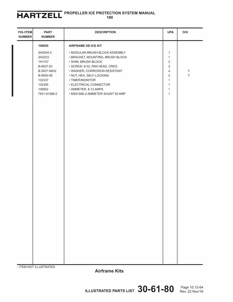
Page 10.12-64Rev. 22 Nov/16 ILLUSTRATED PARTS LIST 30-61-80
PROPELLER ICE PROTECTION SYSTEM MANUAL180
FIG./ITEM PART DESCRIPTION UPA O/H NUMBER NUMBER
- ITEM NOT ILLUSTRATEDAirframe Kits
106855 AIRFRAME DE-ICE KIT
3H2044-3 • MODULAR BRUSH BLOCK ASSEMBLY 1 3H2223 • BRACKET, MOUNTING, BRUSH BLOCK 1 1H1157 • SHIM, BRUSH BLOCK 2 B-6637-52 • SCREW, 8-32, PAN HEAD, CRES. 2 B-3837-N832 • WASHER, CORROSION RESISTANT 4 Y B-6655-08 • NUT, HEX, SELF-LOCKING 2 Y 102337 • TIMER/MONITOR 1 102395 • ELECTRICAL CONNECTOR 1 106852 • AMMETER, 8-12 AMPS 1 7931-91586-2 • MS91586-2 AMMETER SHUNT 50 AMP 1