harry strunk lake 2006 sedimentation survey strunk lake 2006 sedimentation survey u.s. department of...
TRANSCRIPT

Harry Strunk Lake 2006 Sedimentation Survey
U.S. Department of the Interior Bureau of Reclamation Technical Service Center Denver, Colorado December 2006

i
REPORT DOCUMENTATION PAGE Form Approved OMB No. 0704-0188
The public reporting burden for this collection of information is estimated to average 1 hour per response, including the time for reviewing instructions, searching existing data sources, gathering and maintaining the data needed, and completing and reviewing the collection of information. Send comments regarding this burden estimate or any other aspect of this collection of information, including suggestions for reducing the burden, to Department of Defense, Washington Headquarters Services, Directorate for Information Operations and Reports (0704-0188), 1215 Jefferson Davis Highway, Suite 1204, Arlington, VA 22202-4302. Respondents should be aware that notwithstanding any other provision of law, no person shall be subject to any penalty for failing to comply with a collection of information if it does not display a currently valid OMB control number. PLEASE DO NOT RETURN YOUR FORM TO THE ABOVE ADDRESS. 1. REPORT DATE December 2006
2. REPORT TYPE
3. DATES COVERED (From – To)
5a. CONTRACT NUMBER 5b. GRANT NUMBER
4. TITLE AND SUBTITLE Harry Strunk Lake 2006 Sedimentation Survey
5c. PROGRAM ELEMENT NUMBER 5d. PROJECT NUMBER 5e. TASK NUMBER
6. AUTHOR(S) Ronald L. Ferrari
5f. WORK UNIT NUMBER
7. PERFORMING ORGANIZATION NAME(S) AND ADDRESS(ES) Bureau of Reclamation, Technical Service Center, Denver CO 80225-0007
8. PERFORMING ORGANIZATION REPORT NUMBER
10. SPONSOR/MONITOR'S ACRONYM(S)
9. SPONSORING/MONITORING AGENCY NAME(S) AND ADDRESS(ES) Bureau of Reclamation, Technical Service Center, Denver CO 80225-0007 11. SPONSOR/MONITOR'S REPORT
NUMBER(S)
12. DISTRIBUTION/AVAILABILITY STATEMENT 13. SUPPLEMENTARY NOTES Hard copy available at Bureau of Reclamation Technical Service Center, Denver, Colorado 14. ABSTRACT The Bureau of Reclamation (Reclamation) surveyed Harry Strunk Lake in May 2006 to develop new reservoir topography and compute a present storage-elevation relationship (area-capacity tables). The 2006 underwater survey, conducted between reservoir elevation 2,365.7 and 2,365.9 feet (project datum), used sonic depth recording equipment interfaced with a real-time kinematic (RTK) global positioning system (GPS) that gave continuous sounding positions throughout the underwater portion of the reservoir covered by the survey vessel. Above-water topography was mapped by digitizing a reservoir contour from the U.S. Geological Survey quadrangle (USGS quad) maps of the reservoir area. Using the 2006 survey data, the digitized contour was adjusted throughout the reservoir due to shoreline erosion and in the upper reservoir area due to the sediment delta. Due to the lack of above water data, this study assumed no change since the 1981 range line survey from elevation 2,366.1 and above. As of May 2006, at conservation pool elevation 2,366.1, the surface area was 1,840 acres with a total capacity of 34,647 acre-feet. Since dam closure on August 8, 1949, about 6,473 acre-feet of sediment has accumulated below elevation 2,366.1, resulting in a 15.7 percent loss in reservoir volume. 15. SUBJECT TERMS reservoir area and capacity/ sedimentation/ reservoir surveys/ sonar/ sediment distribution/ contour area/ reservoir area/ sedimentation survey/ global positioning system/ lake/ bathymetry 16. SECURITY CLASSIFICATION OF: 19a. NAME OF RESPONSIBLE PERSON
a. REPORT
b. ABSTRACT a. THIS PAGE
17. LIMITATION OF ABSTRACT
18. NUMBER OF PAGES
19b. TELEPHONE NUMBER (Include area code)
Standard Form 298 (Rev. 8/98) Prescribed by ANSI Std. Z39.18

U.S. Department of the Interior Bureau of Reclamation Technical Service Center Sedimentation and River Hydraulics Group Denver, Colorado December 2006
Harry Strunk Lake 2006 Sedimentation Survey prepared by Ronald L. Ferrari
Mission Statements
The mission of the Department of the Interior is to protect and provide access to our Nation's natural and cultural heritage and honor our trust responsibilities to Indian Tribes and our commitments to island communities.
___________________________ The mission of the Bureau of Reclamation is to manage, develop, and protect water and related resources in an environmentally and economically sound manner.
Acknowledgments Reclamation's Sedimentation and River Hydraulics Group (Sedimentation Group) of the Technical Service Center (TSC) prepared and published this report. Ronald Ferrari of the TSC and Mark Rouse of the McCook Field Office in the Great Plains Region conducted the bathymetric survey. Ron Ferrari of the TSC completed the data processing needed to generate the new topographic map and area-capacity tables. Sharon Nuanes of the TSC developed digital data sets needed for the final topographic map. Dave Varyu developed a table that provides more accurate means to present the summary of the reservoir sediment data. Kent Collins of the TSC performed the technical peer review of this documentation.
Reclamation Report This report was produced by the Bureau of Reclamation’s Sedimentation and River Hydraulics Group (Mail Code 86-68540), PO Box 25007, Denver, Colorado 80225-0007. http://www.usbr.gov/pmts/sediment/ Disclaimer No warranty is expressed or implied regarding the usefulness or completeness of the information contained in this report. References to commercial products do not imply endorsement by the Bureau of Reclamation and may not be used for advertising or promotional purposes.
Table of Contents Page
Introduction.........................................................................................................................1 Summary and Conclusions .................................................................................................2 Control Survey Data Information .......................................................................................4 Reservoir Operations ..........................................................................................................4 Hydrographic Survey Equipment and Method ...................................................................5 Reservoir Area and Capacity ..............................................................................................6
Topography Development ............................................................................................6 Shoreline Erosion .........................................................................................................9 Development of the 2006 Harry Strunk Lake Surface Areas.....................................11 2006 Storage Capacity................................................................................................12
2006 Reservoir Sediment Analyses ..................................................................................12 References......................................................................................................................... 18 18
Index of Figures
Figure 1 - Reclamation Reservoirs located in Nebraska.....................................................1 Figure 2 - Survey vessel with mounted instrumentation on Jackson Lake in Wyoming. ...5 Figure 3 - Harry Strunk Lake topographic map. .................................................................8 Figure 4 - Eroded Shoreline. ...............................................................................................9 Figure 5 - Large areas of erosion occurring above normal reservoir water surface,
elevation 2,366. ........................................................................................................10 Figure 6 - View of shoreline erosion over extensive area of reservoir. ............................10 Figure 7 - Typical sediment deposition profile. ................................................................13 Figure 8 - Harry Strunk Lake area and capacity plots. ..................................................... 17
Index of Tables Table 1 - Reservoir sediment data summary (page 1 of 2). ..............................................14 Table 2 - Summary of 2006 survey results. ......................................................................16
iv

Harry Strunk Lake 2006 Sedimentation Survey
Introduction Medicine Creek Dam and Harry Strunk Lake are principal features of the Frenchman-Cambridge Division of the Pick-Sloan Missouri Basin Program located in southwestern Nebraska. Additional storage features are Swanson and Hugh Butler Lakes, and Enders Reservoir. The four dams, reservoirs, and irrigation systems provide storage to irrigate 66,161 acres of project lands, flood control, fish and wildlife conservation, and recreation along the Republican River and its three tributaries of Red Willow and Medicine Creeks, and the Frenchman River. Medicine Creek Dam and Harry Strunk Lake in Frontier County on Medicine Creek are located about seven miles northwest of Cambridge and 60 miles south east of North Platte, Nebraska (figure 1).
Figure 1 - Reclamation Reservoirs located in Nebraska.
1

Medicine Creek Dam is an earthfill structure that was completed in August of 1949. The dam’s dimensions are as follows:
Hydraulic height1 86 feet Structural height 165 feet Crest length 5,665 feet Crest elevation 2,415.0 feet2
The spillway, crest elevation 2,386.2, is a concrete uncontrolled ogee overflow crest located in the left abutment of the dam (Bureau of Reclamation, 1964). The discharge capacity is 97,800 cubic feet per second (cfs) at maximum reservoir elevation 2,408.9. A slot 13 feet wide and 20.1 feet deep is provided between the two center piers of the spillway and has a crest elevation of 2,366.1 feet, the normal reservoir water surface. The discharge capacity is 3,780 cfs through the 13-foot center notch with the reservoir at elevation 2,386.2. A river outlet works is located near the right abutment and consists of a concrete horseshoe conduit 8-feet diameter containing operating valves and a 44-inch steel pipe for controlled releases from the reservoir. The discharge capacity is 390 cfs at spillway crest elevation 2,366.1. The drainage area above Medicine Creek Dam is approximately 880 square miles of which only 642 square miles is considered contributing runoff. The additional 238 square miles of sand hill area yields base flows through the subsurface drainage, (Bureau of Reclamation, 2003). The reservoir extends 8.5 miles up Medicine Creek at reservoir elevation 2,366.1 with an average reservoir width of 0.34 miles (Bureau of Reclamation, 1964).
Summary and Conclusions This Reclamation report presents the 2006 results of the survey of Harry Strunk Lake. The primary objectives of the survey were to gather data needed to: $ develop lake topography $ compute area-capacity relationships $ estimate storage depletion, by sediment deposition, since dam closure The on-line positioning user service (OPUS) with real-time kinematic (RTK) global positioning system (GPS) control survey established a horizontal and 1The definition of such terms as “hydraulic height,” “structural height,” etc. may be found in manuals such as Reclamation’s Design of Small Dams and Guide for Preparation of Standing Operating Procedures for Dams and Reservoirs, or ASCE’s Nomenclature for Hydraulics.
2Elevations in feet. All elevations based on the original project datum established by U.S. Bureau of Reclamation that was reported to be the National Geodetic Vertical Datum of 1929 (NGVD29) and around 0.9 feet lower than the North American Vertical Datum of 1988 (NAVD88).
2

vertical control network near the reservoir for the hydrographic survey. OPUS is operated by the National Geodetic Survey (NGS) and allows users to submit GPS data files where it is processed with known point data to determine positions of points relative to the national control network. Initially, the GPS base was set over Reclamation brass cap “155 RP” that is located near the right abutment of the dam. To begin the collection process, an absolute position with the single GPS unit was measured. This position data was later corrected using the base station data, collected throughout the day, submitted to OPUS. During the bathymetric survey, three base station locations were used and all three sites were submitted to the OPUS web site for computations and verified, with good results, using RTK GPS. The horizontal control was in Nebraska state plane coordinates in the North American Datum of 1983 (NAD83) and the vertical control was tied to the National American Vertical Datum of 1988 (NAVD88) and the Reclamation project vertical datum. All elevations in this report are referenced to Reclamation’s project or construction vertical datum that appears to be tied to the National Geodetic Vertical Datum of 1929 (NGVD29) that is around 0.9 feet lower than NAVD88. The May 2006 underwater survey was conducted between reservoir elevation 2,365.7 and 2,365.9. The bathymetric survey used sonic depth recording equipment interfaced with RTK GPS for determining sounding locations within the reservoir. The system continuously recorded depth and horizontal coordinates of the survey boat as it navigated along grid lines covering Harry Strunk Lake. The positioning system provided information to allow the boat operator to maintain a course along these grid lines. Water surface elevations recorded by Reclamation’s reservoir gauge during the time of collection were used to convert the sonic depth measurements to reservoir bottom elevations. The above-water topography was determined by digitizing existing contour lines from the USGS quad of the reservoir area. During the bathymetric survey the boat location plotted outside these contours indicating extensive shoreline erosion has occurred throughout this reservoir. The contour locations where adjusted where this occurred. The previous surveys also documented shoreline erosion (Bureau of Reclamation, 1964). The Harry Strunk Lake topographic map is a combination of the adjusted digitized contour and the 2006 underwater survey data. A computer graphics program generated the 2006 reservoir surface areas at predetermined contour intervals from the collected reservoir area. The 2006 area and capacity tables were produced by a computer program that used measured contour surface areas and a curve-fitting technique to compute area and capacity at prescribed elevation increments (Bureau of Reclamation, 1985). Tables 1 and 2 contain summaries of Harry Strunk Lake and watershed characteristics for the 2006 survey. The 2006 survey determined that the reservoir has a total storage capacity of 193,020 acre-feet and a surface area of 5,784 acres at surcharge pool elevation 2,408.9. Since closure in August 1949,
3

the reservoir has an estimated volume change of 6,473 acre-feet below conservation reservoir elevation 2,366.1. This volume represents a 15.7 percent loss in total original capacity at this elevation.
Control Survey Data Information Prior to the bathymetric survey, a control network was set by the bathymetric survey crew and used throughout the survey. Initially, the RTK GPS base station was set over marker “155 RP” that is located in an open field near the right abutment of dam. The coordinates for this point were determined by processing the first day of collected raw data through the NGS service OPUS. During the bathymetric survey, three base station locations were used and all three sites were submitted to the OPUS web site for computations and verified with RTK GPS measurements. The horizontal control was in Nebraska state plane coordinates in NAD83 and the vertical control was tied to NAVD88 and the Reclamation project vertical datum. All elevations in this report are referenced to Reclamation’s project or construction vertical datum that is reference to NGVD29 and around 0.9 feet lower than NAVD88. Following are the coordinates determined during this survey at the indicated locations. Elevation Elevation Location North West (NAVD88) (NGVD29) 155-RP 198,278.56 1,577,534.323 2,402.57 Westmaster 197,860.39 1,575,856.569 2,418.39 2,417.502 Section 35 220,592.17 1,575,428.521 2,477.26 RL1-R 198,437.22 1,577,411.486 2,405.12 2,404.22
Reservoir Operations Harry Strunk Lake is part of the Frenchman-Cambridge Division of the Pick-Sloan Missouri Basin Program that provides storage for irrigation, flood control, fish and wildlife conservation, recreation and sediment control. The May 2006 capacity table shows 193,020 acre-feet of total storage below the maximum water surface elevation 2,408.9, table 2. The 2006 survey measured a minimum lake bottom elevation of 2,320.1. The following values are from the May 2006 capacity table:
$ 105,659 acre-feet of surcharge between elevation 2,386.2 and 2,408.9. $ 52,714 acre-feet of flood control between elevation 2,366.1 and 2,386.2.
$ 26,750 acre-foot of active storage between elevation 2,343.0 and 2,366.1. $ 4,489 acre-foot of inactive storage between elevation 2,335.0 and 2,343.0. $ 3,408 acre-foot of dead storage below 2,335.0.
4

Harry Strunk Lake computed annual inflow and reservoir stage records are listed by calendar year on table 1 for the operation period August 1949 through May 2006. The inflow values were computed by the Great Plains Regional Office and show annual fluctuation with a computed average inflow of 46,300 acre-feet per year. The maximum reservoir elevation was 2,374.1, recorded during water year 1960, and after initial filling, minimum recorded elevation was 2,340.4 during water year 1978.
Hydrographic Survey Equipment and Method The hydrographic survey equipment was mounted in the cabin of a 24-foot trihull aluminum vessel equipped with twin in-board motors, figure 2. The hydrographic system included a GPS receiver with a built-in radio, a depth sounder, a helmsman display for navigation, a computer, and hydrographic system software for collecting the underwater data. An on-board generator supplied power to all the equipment. The shore equipment included a second GPS receiver with an external radio. The GPS receiver and antenna were mounted on a survey tripod over a known datum point and a 12-volt battery provided the power for the shore unit.
Figure 2 - Survey vessel with mounted instrumentation on Jackson Lake in Wyoming.
The Sedimentation and River Hydraulics Group uses RTK GPS with the major benefit being precise heights measured in real time to monitor water surface elevation changes. The basic output from a RTK receiver are precise 3-D coordinates in latitude, longitude, and height with accuracies on the order of 2 centimeters horizontally and 3 centimeters vertically. The output is on the GPS datum of WGS-84 that the hydrographic collection software converted into
5
Nebraska’s state plane coordinates in NAD83. The RTK GPS system employs two receivers that track the same satellites simultaneously just like with differential GPS. Harry Strunk Lake hydrographic survey was conducted in May of 2006 between reservoir elevation 2,365.7 and 2,365.9 (Reclamation project datum). The bathymetric survey was conducted using sonic depth recording equipment, interfaced with a RTK GPS, capable of determining sounding locations within the reservoir. The survey system software continuously recorded reservoir depths and horizontal coordinates as the survey boat moved along closely spaced grid lines covering the reservoir area. Most transects (grid lines) were run somewhat parallel along an upstream-downstream river alignment of the reservoir at around 150-foot spacing. Data was collected along the shore by the survey vessel for the majority of the reservoir. The survey vessel's guidance system gave directions to the boat operator to assist in maintaining the course along these predetermined lines. During each run, the depth and position data were recorded on the notebook computer hard drive for subsequent processing. The 2006 underwater data was collected by a depth sounder that was calibrated by lowering an instrument that measured the sound velocity of the reservoir water column. The individual depth soundings were adjusted by the speed of sound of the measurements that can vary with density, salinity, temperature, turbidity, and other conditions. The soundings were further verified by lowering a weighted cable below the boat with beads marking known depths. The collected data were digitally transmitted to the computer collection system via a RS-232 port. The depth sounder also produced an analog hard-copy chart of the measured depths. These graphed analog charts were analyzed during post-processing, and when the analog charted depths indicated a difference from the computer recorded bottom depths, the computer data files were modified. The water surface elevations at the dam, recorded by a Reclamation gauge, were used to convert the sonic depth measurements to true lake-bottom elevations. Additional information on collection and analysis procedures can be found online, (Corps of Engineers, January 2002) and (Ferrari, R.L., 2006).
Reservoir Area and Capacity
Topography Development
The topography of Harry Strunk Lake was developed from the 2006 collected underwater data and the digitized contour from the USGS quad maps developed from aerial photography dated 1952. The digitized contour line was elevation 2,366 and the enclosed contour area, with the island surfaces removed, was within a few percent of the 1951 survey surface area results at the same elevation. The
6

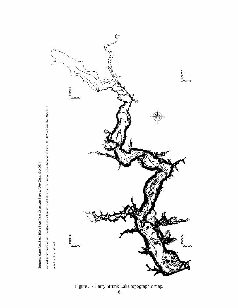
2006 survey data was used to adjust the digitized contour due to the above water sediment delta that had formed since 1952 in the upper reservoir area and the extensive shoreline erosion that has occurred throughout this reservoir. The best means to truly develop this contour and the rest of the above water reservoir area would be by a detailed aerial survey. The adjusted contour, elevation 2,366, was used to perform a hardclip around the 2006 data of Harry Strunk Lake. This hardclip was used during the triangular irregular network (TIN) development so interpolation did not occur outside the enclosed polygon. This contour was selected since it was the closest data available to represent the water surface during the 2006 survey. Using ARCEDIT, the 2006 underwater and the digitized 2,366 contour were plotted. The plot showed that the underwater data did not lie completely within the original elevation 2,366 contour from the USGS quad maps. The 2,366 contour was modified to include the entire underwater data set within the enclosed polygon. Using select and move commands within ARCEDIT, the vertices of the clip were shifted to contain the 2006 underwater data. This adjusted clip was assigned an elevation of 2,366. Contours for the reservoir below elevation 2,366 were computed from the 2006 data sets using the triangular irregular network (TIN) surface-modeling package within ARC/INFO. A TIN is a set of adjacent non-overlapping triangles computed from irregularly spaced points with x,y coordinates and z values. TIN was designed to deal with continuous data such as elevations. The TIN software uses a method known as Delaunay's criteria for triangulation where triangles are formed among all data points within the polygon clip. The method requires that a circle drawn through the three nodes of a triangle will contain no other point, meaning that sample points are connected to their nearest neighbors to form triangles using all collected data. This method preserves all collected survey points. Elevation contours are then interpolated along the triangle elements. The TIN method is discussed in detail in the ARC/INFO V7.0.2 Users Documentation, (ESRI, 1992). The linear interpolation option of the ARC/INFO TINCONTOUR command was used to interpolate contours from the Harry Strunk Lake TIN. The areas of the enclosed contour polygons at one-foot increments were developed from the survey data for elevations 2,322.0 through 2,362.0. Since no complete reservoir aerial data was collected, this study assumed no change in reservoir surface area, since the 1981 survey, for elevation 2,366.0 and above. Since there was limited underwater data collected during the 2006 survey, above elevation 2,362, this study only used surface area development from elevation 2,362 and below. The reservoir contour topography at 2-foot intervals is presented on figure 3.
7
8
Figure 3 - Harry Strunk Lake topographic map.

Shoreline Erosion
The 2006 underwater survey witnessed extensive shoreline erosion throughout the reservoir area. During collection, the GPS boat positions were found at times to be outside the digitized USGS quad contour locations, indicating the boat was on solid ground. The USGS quad contour was developed from aerial photography flown in the 1950’s and at times, the position of the boat was tens of feet outside their boundary. Even with the extensive shore erosion that has occurred since dam closure, the survey vessel was able to maneuver close to the vertical banks in deep water conditions where previous shore material had collapsed into the reservoir. It appears that over time the collapsed material washes further into the reservoir by the wave action, similar to ocean waves smoothing the beaches. This is possible because the material dissipates in the water and consists of little to no rock or large cobble. Following are pictures showing the shoreline erosion and its affect on the reservoir, figures 4 through 6.
Figure 4 - Eroded Shoreline.
9

Figure 5 - Large areas of erosion occurring above normal reservoir water surface, elevation 2,366.
Figure 6 - View of shoreline erosion over extensive area of reservoir.
10
The above photographs show the extent of the shoreline erosion that has occurred throughout the reservoir. If the erosion were just below the reservoir high water mark, the total volume of the reservoir would not be greatly affected. In that case, the gain in surface area and resulting volume in the upper reservoir elevation zone would be offset by the loss of surface area and volume in the lower elevations of the reservoir due to the depositing material from the banks. The photographs (figures 4 through 6) show a large amount of the eroded material above the normal or conservation reservoir elevation 2366.1, meaning that a portion of the loss of the original total reservoir volume is due to material from reservoir shoreline erosion along with incoming river sediments. The only means to accurately measure the extent of the shoreline erosion would be by an extensive above water survey. The shoreline erosion was previously documented in the 1962 sedimentation survey report, with photographs and cross section plots of several of the sediment rangelines revealing the extensive impact of the reservoir wave action. The banks are composed of loessial soil which exhibits the characteristic of being able to stand on almost vertical slopes, but offers little or no resistance to the erosive force of the waves (Bureau of Reclamation, 1964). It is assumed the majority of the bank erosion occurred during the initial filling and early years of the reservoir, but it still occurs today to a lesser extent.
Development of the 2006 Harry Strunk Lake Surface Areas
The 2006 surface areas for Harry Strunk Lake were computed at 1-foot increments, from elevation 2,321.0 through 2,366.0, directly from the TIN that covered the Harry Strunk Lake within the hard clip area only. This TIN was developed within the hardclip area that included the digitized elevation 2,366.0 contour that was modified for the shoreline erosion that has occurred throughout the lake area. These calculations were performed using the ARCGIS surface area and volume command that computes areas at user-specified elevations directly from the TIN and includes all regions of equal elevation. For the purpose of this study, the measured 2006 survey areas at 1-foot increments from elevation 2,321.0 through 2,362.0 were used to compute the new area and capacity tables. There were insufficient 2006 surveyed data points, for accurate computer development of surface areas at elevations above 2,362.0. Straight line interpolation was used to compute the surface areas between elevations 2,362.0 and 2,366.0. This study assumed no change in surface area, since the 1981 survey, from elevation 2,366.0 and above.
11

2006 Storage Capacity
The storage-elevation relationships based on the measured surface areas were developed using the area-capacity computer program ACAP (Bureau of Reclamation, 1985). The ACAP program can compute the area and capacity at elevation increments from 0.01 to 1.0 foot by linear interpolation between the given contour surface areas. The program begins by testing the initial capacity equation over successive intervals to ensure that the equation fits within an allowable error limit. The error limit was set at 0.000001 for Harry Strunk Lake. The capacity equation is then used over the full range of intervals fitting within the allowable error limit. For the first interval at which the initial allowable error limit is exceeded, a new capacity equation (integrated from basic area curve over that interval) is utilized until it exceeds the error limit. Thus, the capacity curve is defined by a series of curves, each fitting a certain region of data. Differentiating the capacity equations, which are of second order polynomial form, final area equations are derived:
y = a1 + a2x + a3x2
where: y = capacity
x = elevation above a reference base a1 = intercept a2 and a3 = coefficients
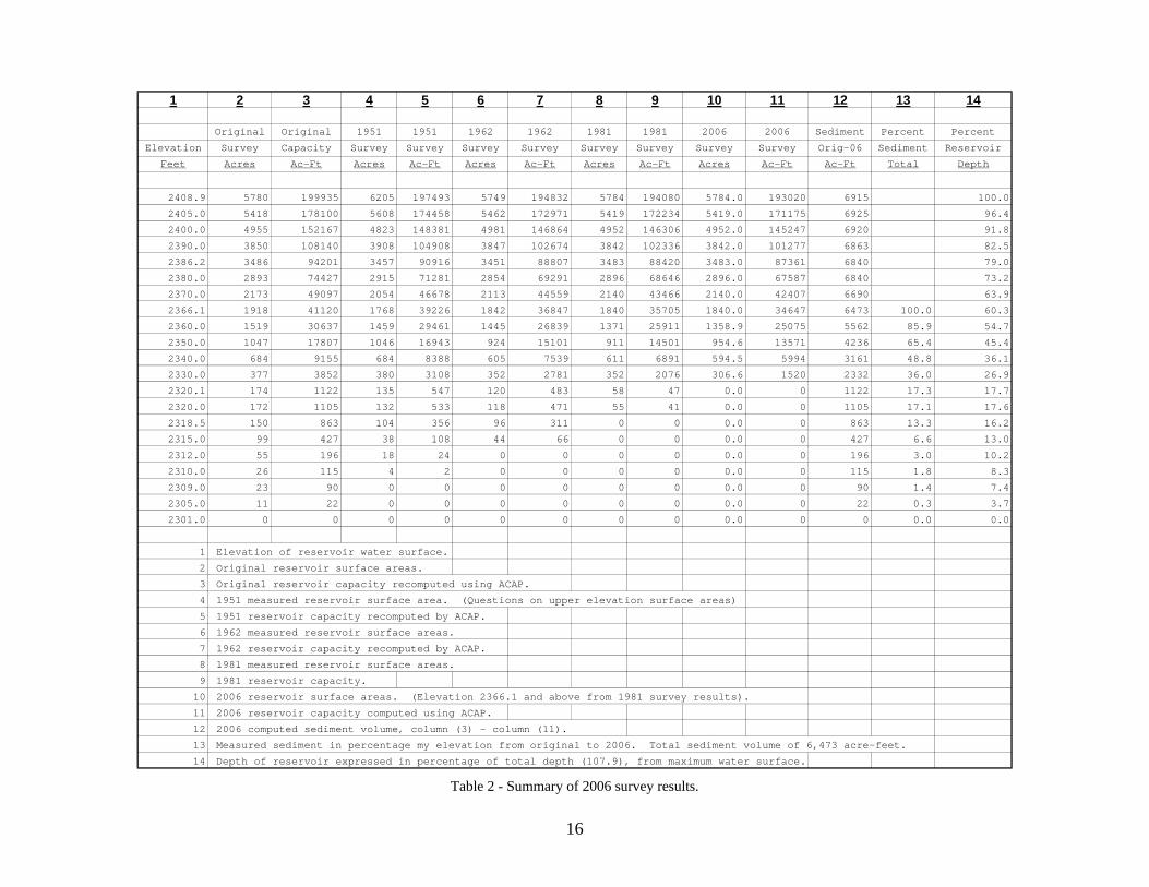
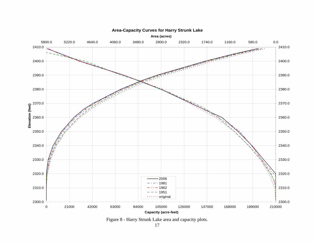
Results of the Harry Strunk Lake area and capacity computations are listed in a separate set of 2006 area and capacity tables and have been published for the 0.01, 0.1 and 1-foot elevation increments (Bureau of Reclamation 2006). A description of the computations and coefficients output from the ACAP program is included with these tables. The original, 1951, 1962, 1981, and 2006 area-capacity relationships are listed on table 2 and the curves are plotted on figure 8. As of May 2006, at conservation use elevation 2,366.1, the surface area was 1,840 acres with a total capacity of 34,647 acre-feet.
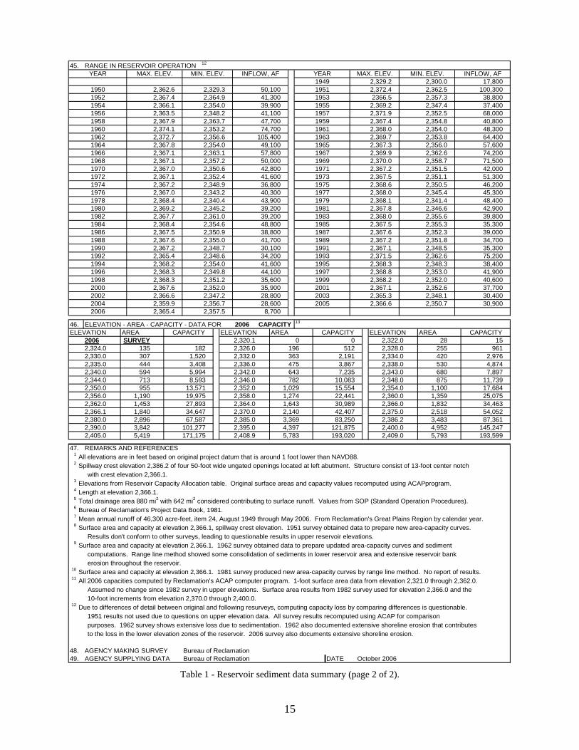
2006 Reservoir Sediment Analyses Results of the 2006 Harry Strunk Lake area and capacity computations are listed in table 1 and columns 10 and 11 of table 2. Columns 2 and 3 of table 2 list the original area and capacity values and the results from the 1951, 1962, and 1981 surveys are also listed. Column 12 lists the capacity differences between the original and 2006 survey results due to sediment inflow and bank erosion. Figure 8 is a plot of the Harry Strunk Lake surface area and capacity values for all the listed surveys and illustrates the differences between the surveys. The comparisons show that the total reservoir capacity in 2006 is 6,473 acre-feet less than the original volume at conservation reservoir elevation 2,366.1.
12
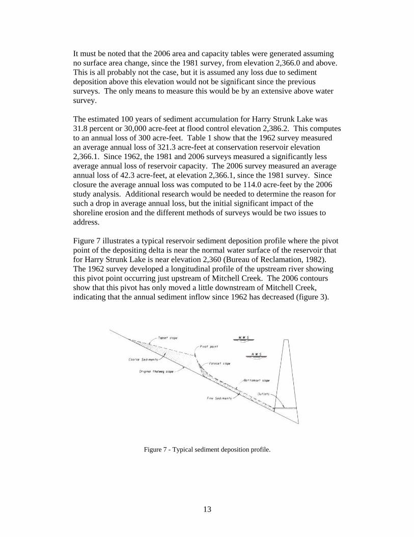
It must be noted that the 2006 area and capacity tables were generated assuming no surface area change, since the 1981 survey, from elevation 2,366.0 and above. This is all probably not the case, but it is assumed any loss due to sediment deposition above this elevation would not be significant since the previous surveys. The only means to measure this would be by an extensive above water survey. The estimated 100 years of sediment accumulation for Harry Strunk Lake was 31.8 percent or 30,000 acre-feet at flood control elevation 2,386.2. This computes to an annual loss of 300 acre-feet. Table 1 show that the 1962 survey measured an average annual loss of 321.3 acre-feet at conservation reservoir elevation 2,366.1. Since 1962, the 1981 and 2006 surveys measured a significantly less average annual loss of reservoir capacity. The 2006 survey measured an average annual loss of 42.3 acre-feet, at elevation 2,366.1, since the 1981 survey. Since closure the average annual loss was computed to be 114.0 acre-feet by the 2006 study analysis. Additional research would be needed to determine the reason for such a drop in average annual loss, but the initial significant impact of the shoreline erosion and the different methods of surveys would be two issues to address. Figure 7 illustrates a typical reservoir sediment deposition profile where the pivot point of the depositing delta is near the normal water surface of the reservoir that for Harry Strunk Lake is near elevation 2,360 (Bureau of Reclamation, 1982). The 1962 survey developed a longitudinal profile of the upstream river showing this pivot point occurring just upstream of Mitchell Creek. The 2006 contours show that this pivot has only moved a little downstream of Mitchell Creek, indicating that the annual sediment inflow since 1962 has decreased (figure 3).
Figure 7 - Typical sediment deposition profile.
13
1. 2. Medicine Creek 3. STATE Nebraska4. 5. Cambridge 6. COUNTY Frontier7. ° 22 ' 40 " ° 13 ' 00 " 8. 1 9. SPILLWAY CREST EL 2
10. 11. 12. GROSS STORAGE 15CAPACITY, AC-FT
a. 3
b.c.d. 16e.f.g.17. LENGTH OF RESERVOIR 4
18. TOTAL DRAINAGE AREA 5 22. 6
19. NET SEDIMENT CONTRIBUTING AREA 5 23. MEAN ANNUAL RUNOFF 7 INCHES20. LENGTH MILES AVG. WIDTH MILES 24. MEAN ANNUAL RUNOFF 7 ACRE-FEET21. 25. °F °F 6
26. DATE OF 27. 28. 29. 30. 31. C/
3
8
9
26. DATE OF 35. 36
7
26. DATE OF 37. 38.
26. DATE OF 39.AVG. DRY WT. 40. SED. DEP. TONS/MI.2-YR 41. STORAGE LOSS, PCT. 42 SEDIMENT (#/FT3) b. TOTAL b. TOTAL TO INFLOW, PPM
TO DATE DATE a. PER. b. TOT.
43.
56.75/815/06
10
11
NO. OFRANGES OR INTERVALS
105,734 199,93594,201
AREA, AC.
R
SURVEY
V 2.2 2.210/51
D
BEGAN
MAX. ELEVATION MIN. ELEVATION ANNUAL TEMP, MEAN
8/1949MILES
BEGAN
DATE NORMAL
8/1949
OPERATIONS
DATA SHEET NO.
DATESTORAGE
2415.0
RESERVOIR SEDIMENTDATA SUMMARY
Harry Strunk LakeNAME OF RESERVOIR
DATEOFSURVEY
5/00
SURVEY
26. 44.
DATEOF
SURVEY
AT
Y
SURVEY
ACRE - FEET32.
26.
CAPACITY
WATER INFLOW TO DATE, AF
SURVEYPERIOD CAPACITY LOSS, ACRE-FEET
5,2496,120
29,751 41,12011,369
6,120
IN S
a.
TOTALa. /MI.2-YR.c.AVG. ANN.b.
0.075,416
PERIOD
U
SURFACETYPE OF SURVEY
a. MEAN ANN.
31.7 34
TOTAL SEDIMENT DEPOSITS TO DATE, AF
ANNUALPRECIPITATION
1,671,60052,700920,000
AVG. ANNUALa.
6,4730.10
RATIO AF/AF
0.89
0.75
110to
33.
36,8470.7735,704
41,12039,226
Contour (D)Range (D)
Contour (D) 10 - ft 1,918
1 - ft 11
311,840
52 -22RANGE°F
5,7803,486
2,408.9
2,343.02,335.0
1,918793530
960,600
14.
2,386.2
53,081
SURFACE AREA, AC-FT13. ORIGINAL ORIGINAL
S
RVOIR
2,366.1
SE
STORAGEALLOCATION
74,200
34.
18.4
b.
PERIOD WATER INFLOW, ACRE-FEETPERIOD
c.MAX. ANN.
56,500 105,400
40
OWNERSECLAT
25M
TWP.
1
26 WSTREAMNEAREST P.O.TOP OF DAM ELEVATION
DA 5N RANGE
BA
RE
38,300
2386.2
ACRE-FEET
56,500
6/06 75,200 2,632,2005/81
751,60050,000
13.2
5/81 62.142.3126/06
1,143
JOINT USECONSERVATION
1,057
10/51
TOTALa.
0.850.80
170.9114.2
321.312
YRSYRS
25.0
12/62
8/49
12/625/81
10/51 2,08471.4
0.0
PERCENT OF TOTAL SEDIMENT LOCATED WITHIN REACH DESIGNATION10 3020 40
60-70
50-60
70.3 475
0.28
15.70.42
2,408.92,400.0
2,340.02,330.0
2,350.02,340.0
2,400.02,386.2
2,375.02,360.0
90- 100-
2,366.1
30-
2330.0-
4.913.219.115.6
2,350.0 2,360.0
0.4
2,320.1
17.516.2
2,301.0
REACH DESIGNATION PERCENT OF TOTAL ORIGINAL LENGTH OF RESERVOIR12.0
111110-0-11590
70-80
10- 20- 80-
MILES8.5
1.1
DEPTH DESIGNATION RANGE BY RESERVOIR ELEVATION
2,366.12,386.22,375.0
MEAN ANNUAL PRECIPITATION 20
46,300
INCHES1.16SQUARE MILES
SQUARE MILESAVG. WIDTH OF RESERVOIR
100
Bureau of Reclamation
LONG
SURCHARGE
INACTIVEDEAD
TOP OF POOL
FLOOD CONTROLPOWER
0.34
ELEVATION
880
34 1,768
34,647
1,842Range (D)Range (D)
642
PER.PER.
PERCENT OF TOTAL SEDIMENT LOCATED WITHIN DEPTH DESIGNATION
120-125
115-120105
2320.1-
100105-
6/06
E 11.1 13.3
A 12/62
12/62 4,273
6,396
0.27
10.4 4,404
14,063
0.50
0.18
751,600
TOTAL
1,840
TOTALb.MEAN ANN.a.
14,063
c.AVG. ANN.b. /MI.2-YR.
46,300
12 321.3 0.50
12
735
4,273
2,0840.78
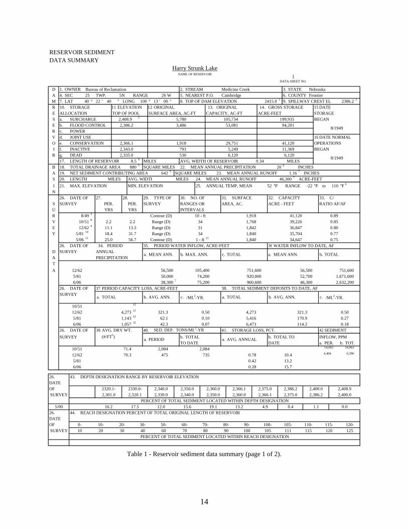
Table 1 - Reservoir sediment data summary (page 1 of 2).
14
15
1
2
3
4
5
6
7
8
9
10
11
12
erosion throughout the reservoir.
30,400
39,8001982 2,367.7 2,361.0 39,200 1983 2,368.0 2,355.6
2,367.1 2,352.6 37,7002002 2,366.6 2,347.2 28,800 2003 2,365.3 2,348.12000 2,367.6 2,352.0 35,900
45,300
1998 2,368.3 2,351.2 35,600 2,368.2 2,352.0 40,6002,368.8 2,353.0
2,334.0 420
1976 2,367.0 2,343.2 40,300 1977 2,368.0 2,345.4
2,332.0 363 2,191
2,360.0 1,359
2,330.0 307 1,520
1,274 22,44119,975 2,358.02,356.0 1,190
2,343.0 6805,994 2,342.02,340.0 5942,338.0 5302,336.0 475444 3,408
1967 2,369.9 2,362.6 74,2001966 2,367.1 2,363.1 57,800
64,4001964 2,367.8 2,354.0 49,100 1965 2,367.3 2,356.0 57,600
2,367.2 2,351.5 42,000
1962 2,372.7 2,356.6 105,400 1963 2,369.7 2,353.8
2,367.0 2,350.6 42,800 19711968 2,367.1 2,357.2 50,000 1969 2,370.0 2,358.7 71,5001970
45. RANGE IN RESERVOIR OPERATION
1,840
135
171,175
2004
193,0202,408.9 5,783
2,385.0
30,9892,364.0 1,643
145,2472,409.0 5,793 193,599
4,9522,400.0
CAPACITY
2,395.0 4,397
2,370.0
AREA CAPACITYELEVATION
54,0522,386.2 3,483 87,3612,375.0 2,518
961
2,366.0 1,832 34,463
4,8747,897
25,075
2,9762,328.0 2552,326.0 196 512
83,250121,875
3,36942,4072,140
643 7,2353,867
782 10,0831,029
2,320.1 0 0
2006 CAPACITYELEVATION AREA
2006 2,365.4 2,357.5 8,7002,366.6 2,350.7 30,9002,359.9 2,356.7 28,600
1997
2005
19992001
41,9001996 2,368.3 2,349.8 44,1001995 2,368.3 2,348.3 38,4001994 2,368.2 2,354.0 41,6001993 2,371.5 2,362.6 75,2001992 2,365.4 2,348.6 34,2001991 2,367.1 2,348.5 35,3001990 2,367.2 2,348.7 30,1001989 2,367.2 2,351.8 34,7001988 2,367.6 2,355.0 41,700
35,3001986 2,367.5 2,350.9 38,800 1987 2,367.6 2,352.3 39,000
2,367.8 2,346.6 42,900
1984 2,368.4 2,354.6 48,800 1985 2,367.5 2,355.3
1980 2,345.2 39,200 1981
2,368.6 2,350.5 46,200
1978 2,340.4 43,900 1979 2,368.1 2,341.4 48,400
1974 2,348.9 36,800 1975
2,354.0 48,300
1972 2,352.4 41,600 1973 2,367.5 2,351.1 51,300
2,353.2 74,700 1961 2,368.0
2,371.9 2,352.5 68,0001958 2,363.7 47,700 1959 2,367.4 2,354.8 40,8001956 2,348.2 41,100 19572,363.5
2,369.22,357.3 38,800
1954 2,354.0 39,900 1955 2,347.4 37,4002,366.1
2,372.4 2,362.5 100,3001952 2,364.9 41,300 2366.51953
2,362.62,367.4
2,300.0 17,800
2,390.0
182
27,89334,64767,587
101,277
1951
MIN. ELEV. INFLOW, AF
1950 2,329.3 50,1001949 2,329.2
MIN. ELEV. INFLOW, AF YEAR MAX. ELEV.
47.
48. Bureau of Reclamation
All elevations are in feet based on original project datum that is around 1 foot lower than NAVD88.Spillway crest elevation 2,386.2 of four 50-foot wide ungated openings located at left abutment. Structure consist of 13-foot center notch
Elevations from Reservoir Capacity Allocation table. Original surface areas and capacity values recomputed using ACAPprogram.
Bureau of Reclamation's Project Data Book, 1981.
REMARKS AND REFERENCES
computations. Range line method showed some consolidation of sediments in lower reservoir area and extensive reservoir bank
12
2,324.0
2,362.02,366.12,380.0
2,405.0
YEAR MAX. ELEV.
49. Bureau of Reclamation October 2006
Surface area and capacity at elevation 2,366.1. 1981 survey produced new area-capacity curves by range line method. No report of results.All 2006 capacities computed by Reclamation's ACAP computer program. 1-foot surface area data from elevation 2,321.0 through 2,362.0. Assumed no change since 1982 survey in upper elevations. Surface area results from 1982 survey used for elevation 2,366.0 and the
1951 results not used due to questions on upper elevation data. All survey results recomputed using ACAP for comparison
to the loss in the lower elevation zones of the reservoir. 2006 survey also documents extensive shoreline erosion.
AGENCY MAKING SURVEY
Mean annual runoff of 46,300 acre-feet, item 24, August 1949 through May 2006. From Reclamation's Great Plains Region by calendar year. Surface area and capacity at elevation 2,366.1, spillway crest elevation. 1951 survey obtained data to prepare new area-capacity curves.
Surface area and capacity at elevation 2,366.1. 1962 survey obtained data to prepare updated area-capacity curves and sediment Results don't conform to other surveys, leading to questionable results in upper reservoir elevations.
AGENCY SUPPLYING DATA DATE
3,8425,419
Length at elevation 2,366.1.Total drainage area 880 mi2 with 642 mi2 considered contributing to surface runoff. Values from SOP (Standard Operation Procedures).
10-foot increments from elevation 2,370.0 through 2,400.0.Due to differences of detail between original and following resurveys, computing capacity loss by comparing differences is questionable.
2006
2,335.0
SURVEY
13
2,322.0 28 15
46. ELEVATION - AREA - CAPACITY - DATA FOR
1,453
2,367.92,374.1
2,367.1
ELEVATION AREA CAPACITY
2,367.2
2,368.42,369.2
1960
2,344.0 713 8,593 2,346.0 2,348.0 875 11,7392,350.0 955 13,571 2,352.0
purposes. 1962 survey shows extensive loss due to sedimentation. 1962 also documented extensive shoreline erosion that contributes
1,100 17,684
with crest elevation 2,366.1.
15,554 2,354.0
2,896
Table 1 - Reservoir sediment data summary (page 2 of 2).
16
1 2 3 4 5 6 7 8 9 10 11 12 13 14
Original Original 1951 1951 1962 1962 1981 1981 2006 2006 Sediment Percent Percent
Elevation Survey Capacity Survey Survey Survey Survey Survey Survey Survey Survey Orig-06 Sediment Reservoir
Feet Acres Ac-Ft Acres Ac-Ft Acres Ac-Ft Acres Ac-Ft Acres Ac-Ft Ac-Ft Total Depth
2408.9 5780 199935 6205 197493 5749 194832 5784 194080 5784.0 193020 6915 100.0
2405.0 5418 178100 5608 174458 5462 172971 5419 172234 5419.0 171175 6925 96.4
2400.0 4955 152167 4823 148381 4981 146864 4952 146306 4952.0 145247 6920 91.8
2390.0 3850 108140 3908 104908 3847 102674 3842 102336 3842.0 101277 6863 82.5
2386.2 3486 94201 3457 90916 3451 88807 3483 88420 3483.0 87361 6840 79.0
2380.0 2893 74427 2915 71281 2854 69291 2896 68646 2896.0 67587 6840 73.2
2370.0 2173 49097 2054 46678 2113 44559 2140 43466 2140.0 42407 6690 63.9
2366.1 1918 41120 1768 39226 1842 36847 1840 35705 1840.0 34647 6473 100.0 60.3
2360.0 1519 30637 1459 29461 1445 26839 1371 25911 1358.9 25075 5562 85.9 54.7
2350.0 1047 17807 1046 16943 924 15101 911 14501 954.6 13571 4236 65.4 45.4
2340.0 684 9155 684 8388 605 7539 611 6891 594.5 5994 3161 48.8 36.1
2330.0 377 3852 380 3108 352 2781 352 2076 306.6 1520 2332 36.0 26.9
2320.1 174 1122 135 547 120 483 58 47 0.0 0 1122 17.3 17.7
2320.0 172 1105 132 533 118 471 55 41 0.0 0 1105 17.1 17.6
2318.5 150 863 104 356 96 311 0 0 0.0 0 863 13.3 16.2
2315.0 99 427 38 108 44 66 0 0 0.0 0 427 6.6 13.0
2312.0 55 196 18 24 0 0 0 0 0.0 0 196 3.0 10.2
2310.0 26 115 4 2 0 0 0 0 0.0 0 115 1.8 8.3
2309.0 23 90 0 0 0 0 0 0 0.0 0 90 1.4 7.4
2305.0 11 22 0 0 0 0 0 0 0.0 0 22 0.3 3.7
2301.0 0 0 0 0 0 0 0 0 0.0 0 0 0.0 0.0
1 Elevation of reservoir water surface.
2 Original reservoir surface areas.
3 Original reservoir capacity recomputed using ACAP.
4 1951 measured reservoir surface area. (Questions on upper elevation surface areas)
5 1951 reservoir capacity recomputed by ACAP.
6 1962 measured reservoir surface areas.
7 1962 reservoir capacity recomputed by ACAP.
8 1981 measured reservoir surface areas.
9 1981 reservoir capacity.
10 2006 reservoir surface areas. (Elevation 2366.1 and above from 1981 survey results).
11 2006 reservoir capacity computed using ACAP.
12 2006 computed sediment volume, column (3) - column (11).
13 Measured sediment in percentage my elevation from original to 2006. Total sediment volume of 6,473 acre-feet.
14 Depth of reservoir expressed in percentage of total depth (107.9), from maximum water surface. Table 2 - Summary of 2006 survey results.
Area-Capacity Curves for Harry Strunk Lake
2300.0
2310.0
2320.0
2330.0
2340.0
2350.0
2360.0
2370.0
2380.0
2390.0
2400.0
2410.0
0 21000 42000 63000 84000 105000 126000 147000 168000 189000 210000Capacity (acre-feet)
Elev
atio
n (fe
et)
2300.0
2310.0
2320.0
2330.0
2340.0
2350.0
2360.0
2370.0
2380.0
2390.0
2400.0
2410.00.0580.01160.01740.02320.02900.03480.04060.04640.05220.05800.0
Area (acres)
2006198119621951original
17Figure 8 - Harry Strunk Lake area and capacity plots.

References American Society of Civil Engineers, 1962. Nomenclature for Hydraulics, ASCE Headquarters, New York. Bureau of Reclamation, 1964. Denver Office, The 1962 Sedimentation Survey of Harry Strunk Lake Nebraska, Denver, CO. Bureau of Reclamation, 1981. Project Data, Denver Office, Denver CO. Bureau of Reclamation, 1985. Surface Water Branch, ACAP85 User's Manual, Technical Service Center, Denver CO. Bureau of Reclamation, 1987(a). Guide for Preparation of Standing Operating Procedures for Bureau of Reclamation Dams and Reservoirs, U.S. Government Printing Office, Denver, CO. Bureau of Reclamation, 1987(b). Design of Small Dams, U.S. Government Printing Office, Denver CO. Bureau of Reclamation, December 2003. Standing Operating Procedures (SOP), Medicine Creek Dam and Harry Strunk Lake, Frenchman-Cambridge Division of the Pick-Sloan Missouri Basin Program, Great Plains Region, Billings, MT. Bureau of Reclamation, May 2006. Harry Strunk Lake Area and Capacity Tables, Frenchman-Cambridge Division of the Pick-Sloan Missouri Basin Program, Great Plains Region, Billings, MT. Corps of Engineers, January 2002. Engineer and Design - Hydrographic Surveying, EM 1110-2-1003, Department of the Army, Washington DC, (www.usace.army.mil/inet/usace-docs/eng-manuals/em1110-2-1003/toc.htm). ESRI, 2006. Environmental Systems Research Institute, Inc. (www.esri.com) Ferrari, R.L., 2006. Reconnaissance Technique for Reservoir Surveys, U.S. Bureau of Reclamation, Denver, Colorado. http://www.usbr.gov/pmts/sediment/projects/index.html
18