harmonized european standard
TRANSCRIPT

Draft ETSI EN 300 328 V1.8.0 (2011-07)
Harmonized European Standard
Electromagnetic compatibilityand Radio spectrum Matters (ERM);
Wideband transmission systems;Data transmission equipment operating
in the 2,4 GHz ISM band andusing wide band modulation techniques;
Harmonized EN covering the essential requirementsof article 3.2 of the R&TTE Directive

ETSI
Draft ETSI EN 300 328 V1.8.0 (2011-07) 2
Reference REN/ERM-TG11-009
Keywords data, ISM, LAN, mobile, radio, regulation, spread
spectrum, SRD, testing, transmission, UHF
ETSI
650 Route des Lucioles F-06921 Sophia Antipolis Cedex - FRANCE
Tel.: +33 4 92 94 42 00 Fax: +33 4 93 65 47 16
Siret N° 348 623 562 00017 - NAF 742 C
Association à but non lucratif enregistrée à la Sous-Préfecture de Grasse (06) N° 7803/88
Important notice
Individual copies of the present document can be downloaded from: http://www.etsi.org
The present document may be made available in more than one electronic version or in print. In any case of existing or perceived difference in contents between such versions, the reference version is the Portable Document Format (PDF).
In case of dispute, the reference shall be the printing on ETSI printers of the PDF version kept on a specific network drive within ETSI Secretariat.
Users of the present document should be aware that the document may be subject to revision or change of status. Information on the current status of this and other ETSI documents is available at
http://portal.etsi.org/tb/status/status.asp
If you find errors in the present document, please send your comment to one of the following services: http://portal.etsi.org/chaircor/ETSI_support.asp
Copyright Notification
No part may be reproduced except as authorized by written permission. The copyright and the foregoing restriction extend to reproduction in all media.
© European Telecommunications Standards Institute 2011.
All rights reserved.
DECTTM, PLUGTESTSTM, UMTSTM and the ETSI logo are Trade Marks of ETSI registered for the benefit of its Members. 3GPPTM and LTE™ are Trade Marks of ETSI registered for the benefit of its Members and
of the 3GPP Organizational Partners. GSM® and the GSM logo are Trade Marks registered and owned by the GSM Association.

ETSI
Draft ETSI EN 300 328 V1.8.0 (2011-07) 3
Contents
Intellectual Property Rights ................................................................................................................................ 8
Foreword ............................................................................................................................................................. 8
Introduction ........................................................................................................................................................ 8
1 Scope ........................................................................................................................................................ 9
2 References ................................................................................................................................................ 9
2.1 Normative references ......................................................................................................................................... 9
2.2 Informative references ...................................................................................................................................... 10
3 Definitions, symbols and abbreviations ................................................................................................. 11
3.1 Definitions ........................................................................................................................................................ 11
3.2 Symbols ............................................................................................................................................................ 13
3.3 Abbreviations ................................................................................................................................................... 13
4 Technical specifications ......................................................................................................................... 14
4.1 Environmental profile ....................................................................................................................................... 14
4.2 Equipment types ............................................................................................................................................... 14
4.2.1 Modulation types ........................................................................................................................................ 14
4.2.2 Adaptive and non-Adaptive equipment ...................................................................................................... 14
4.3 Technical requirements .................................................................................................................................... 14
4.3.1 Technical requirements for Frequency Hopping equipment ....................................................................... 14
4.3.1.1 RF output power .................................................................................................................................... 15
4.3.1.1.1 Definition......................................................................................................................................... 15
4.3.1.1.2 Limit ................................................................................................................................................ 15
4.3.1.1.3 Conformance ................................................................................................................................... 15
4.3.1.2 Duty Cycle, Tx-sequence, Tx-gap ......................................................................................................... 15
4.3.1.2.1 Definition......................................................................................................................................... 15
4.3.1.2.2 Limit ................................................................................................................................................ 15
4.3.1.2.3 Conformance ................................................................................................................................... 15
4.3.1.3 Dwell time, Minimum Frequency Occupation and Hopping Sequence ................................................ 15
4.3.1.3.1 Definition......................................................................................................................................... 16
4.3.1.3.2 Limit ................................................................................................................................................ 16
4.3.1.3.3 Other Requirements ......................................................................................................................... 16
4.3.1.3.4 Conformance ................................................................................................................................... 16
4.3.1.4 Hopping Frequency Separation ............................................................................................................. 16
4.3.1.4.1 Definition......................................................................................................................................... 16
4.3.1.4.2 Limit ................................................................................................................................................ 17
4.3.1.4.3 Conformance ................................................................................................................................... 17
4.3.1.5 Medium Utilisation (MU) factor ........................................................................................................... 17
4.3.1.5.1 Definition......................................................................................................................................... 17
4.3.1.5.2 Limit ................................................................................................................................................ 17
4.3.1.5.3 Conformance ................................................................................................................................... 17
4.3.1.6 Adaptivity (Adaptive Frequency Hopping) ........................................................................................... 17
4.3.1.6.1 Adaptive Frequency Hopping using LBT based DAA .................................................................... 18
4.3.1.6.2 Adaptive Frequency Hopping using other forms of DAA (non-LBT based) .................................. 19
4.3.1.6.3 Short Control Signalling Transmissions .......................................................................................... 20
4.3.1.7 Occupied Channel Bandwidth ............................................................................................................... 20
4.3.1.7.1 Definition......................................................................................................................................... 20
4.3.1.7.2 Limits .............................................................................................................................................. 20
4.3.1.7.3 Conformance ................................................................................................................................... 20
4.3.1.8 Transmitter unwanted emissions in the out-of-band domain ................................................................ 20
4.3.1.8.1 Definition......................................................................................................................................... 20
4.3.1.8.2 Limit ................................................................................................................................................ 20
4.3.1.8.3 Conformance ................................................................................................................................... 21
4.3.1.9 Transmitter unwanted emissions in the spurious domain ...................................................................... 21
4.3.1.9.1 Definition......................................................................................................................................... 21

ETSI
Draft ETSI EN 300 328 V1.8.0 (2011-07) 4
4.3.1.9.2 Limit ................................................................................................................................................ 21
4.3.1.9.3 Conformance ................................................................................................................................... 21
4.3.1.10 Receiver spurious emissions ................................................................................................................. 22
4.3.1.10.1 Definition......................................................................................................................................... 22
4.3.1.10.2 Limit ................................................................................................................................................ 22
4.3.1.10.3 Conformance ................................................................................................................................... 22
4.3.1.11 Receiver Blocking ................................................................................................................................. 22
4.3.1.11.1 Definition......................................................................................................................................... 22
4.3.1.11.2 Limits .............................................................................................................................................. 22
4.3.1.11.3 Conformance ................................................................................................................................... 23
4.3.2 Technical requirements for other types of Wide Band modulation ............................................................ 23
4.3.2.1 RF output power .................................................................................................................................... 23
4.3.2.1.1 Definition......................................................................................................................................... 23
4.3.2.1.2 Limit ................................................................................................................................................ 23
4.3.2.1.3 Conformance ................................................................................................................................... 23
4.3.2.2 Power density ........................................................................................................................................ 23
4.3.2.2.1 Definition......................................................................................................................................... 23
4.3.2.2.2 Limit ................................................................................................................................................ 23
4.3.2.2.3 Conformance ................................................................................................................................... 23
4.3.2.3 Duty Cycle, Tx-sequence, Tx-gap ......................................................................................................... 23
4.3.2.3.1 Definition......................................................................................................................................... 24
4.3.2.3.2 Limit ................................................................................................................................................ 24
4.3.2.3.3 Conformance ................................................................................................................................... 24
4.3.2.4 Medium Utilisation (MU) factor ........................................................................................................... 24
4.3.2.4.1 Definition......................................................................................................................................... 24
4.3.2.4.2 Limit ................................................................................................................................................ 24
4.3.2.4.3 Conformance ................................................................................................................................... 24
4.3.2.5 Adaptivity (Adaptive equipment using modulations other than FHSS) ................................................ 25
4.3.2.5.1 Non-LBT based Detect and Avoid .................................................................................................. 25
4.3.2.5.2 LBT based Detect and Avoid .......................................................................................................... 25
4.3.2.5.3 Short Control Signalling Transmissions .......................................................................................... 27
4.3.2.6 Occupied Channel Bandwidth ............................................................................................................... 28
4.3.2.6.1 Definition......................................................................................................................................... 28
4.3.2.6.2 Limits .............................................................................................................................................. 28
4.3.2.6.3 Conformance ................................................................................................................................... 28
4.3.2.7 Transmitter unwanted emissions in the out-of-band domain ................................................................ 28
4.3.2.7.1 Definition......................................................................................................................................... 28
4.3.2.7.2 Limit ................................................................................................................................................ 28
4.3.2.7.3 Conformance ................................................................................................................................... 29
4.3.2.8 Transmitter unwanted emissions in the spurious domain ...................................................................... 29
4.3.2.8.1 Definition......................................................................................................................................... 29
4.3.2.8.2 Limit ................................................................................................................................................ 29
4.3.2.8.3 Conformance ................................................................................................................................... 29
4.3.2.9 Receiver spurious emissions ................................................................................................................. 29
4.3.2.9.1 Definition......................................................................................................................................... 30
4.3.2.9.2 Limit ................................................................................................................................................ 30
4.3.2.9.3 Conformance ................................................................................................................................... 30
4.3.2.10 Receiver Blocking ................................................................................................................................. 30
4.3.2.10.1 Definition......................................................................................................................................... 30
4.3.2.10.2 Limits .............................................................................................................................................. 30
4.3.2.10.3 Conformance ................................................................................................................................... 30
5 Essential radio test suites ........................................................................................................................ 31
5.1 Conditions for testing ....................................................................................................................................... 31
5.1.1 Normal and extreme test conditions............................................................................................................ 31
5.1.1.1 Normal test conditions .......................................................................................................................... 31
5.1.1.1.1 Normal temperature and humidity ................................................................................................... 31
5.1.1.1.2 Normal power source ...................................................................................................................... 31
5.1.1.2 Extreme test conditions ......................................................................................................................... 31
5.1.1.2.1 Extreme temperatures ...................................................................................................................... 31
5.1.1.2.2 Extreme power source voltages ....................................................................................................... 31
5.1.2 Test mode.................................................................................................................................................... 31

ETSI
Draft ETSI EN 300 328 V1.8.0 (2011-07) 5
5.1.3 Antennas and transmit operating modes ..................................................................................................... 32
5.1.3.1 Integrated and dedicated antennas ......................................................................................................... 32
5.1.3.2 Smart antenna systems and related operating modes ............................................................................ 32
5.1.3.2.1 Operating mode 1 (single antenna) .................................................................................................. 32
5.1.3.2.2 Operating mode 2 (multiple antennas, no beamforming) ................................................................ 32
5.1.3.2.3 Operating mode 3 (multiple antennas, with beamforming) ............................................................. 32
5.1.3.3 Output power setting ............................................................................................................................. 32
5.1.4 Adaptive and Non-adaptive equipment....................................................................................................... 33
5.1.5 Presentation of equipment .......................................................................................................................... 33
5.1.5.1 Testing of stand-alone equipment ......................................................................................................... 33
5.1.5.2 Testing of host connected equipment and plug-in radio equipment ...................................................... 33
5.1.5.2.1 The use of a host or test jig for testing Plug-In radio equipment ..................................................... 33
5.1.5.2.2 Testing of combinations .................................................................................................................. 33
5.1.6 Test Fixture ................................................................................................................................................. 34
5.2 Interpretation of the measurement results ........................................................................................................ 34
5.3 Test procedures for essential radio test suites................................................................................................... 35
5.3.1 Product Information .................................................................................................................................... 35
5.3.2 RF output power, Duty Cycle, Tx-sequence, Tx-gap, Medium Utilisation ................................................ 36
5.3.2.1 Test conditions ...................................................................................................................................... 36
5.3.2.2 Test method ........................................................................................................................................... 36
5.3.2.2.1 Conducted measurements ................................................................................................................ 36
5.3.2.2.2 Radiated measurements ................................................................................................................... 38
5.3.3 Power density.............................................................................................................................................. 38
5.3.3.1 Test conditions ...................................................................................................................................... 38
5.3.3.2 Test method ........................................................................................................................................... 38
5.3.3.2.1 Conducted measurement.................................................................................................................. 38
5.3.3.2.2 Radiated measurement ..................................................................................................................... 39
5.3.4 Dwell time, Minimum Frequency Occupation and Hopping Sequence ...................................................... 40
5.3.4.1 Test conditions ...................................................................................................................................... 40
5.3.4.2 Test method ........................................................................................................................................... 40
5.3.4.2.1 Conducted measurements ................................................................................................................ 40
5.3.4.2.2 Radiated measurements ................................................................................................................... 41
5.3.5 Hopping Frequency Separation................................................................................................................... 42
5.3.5.1 Test conditions ...................................................................................................................................... 42
5.3.5.2 Test method ........................................................................................................................................... 42
5.3.5.2.1 Conducted measurements ................................................................................................................ 42
5.3.5.2.2 Radiated measurements ................................................................................................................... 44
5.3.6 Void ............................................................................................................................................................ 44
5.3.7 Adaptivity (Channel access mechanism) .................................................................................................... 44
5.3.7.1 Test conditions ...................................................................................................................................... 44
5.3.7.2 Test Method .......................................................................................................................................... 44
5.3.7.2.1 Conducted measurements ................................................................................................................ 44
5.3.7.2.2 Radiated measurements ................................................................................................................... 51
5.3.8 Occupied Channel Bandwidth .................................................................................................................... 51
5.3.8.1 Test conditions ...................................................................................................................................... 51
5.3.8.2 Test method ........................................................................................................................................... 52
5.3.8.2.1 Conducted measurement.................................................................................................................. 52
5.3.8.2.2 Radiated measurement ..................................................................................................................... 52
5.3.9 Transmitter unwanted emissions in the out-of-band domain ...................................................................... 52
5.3.9.1 Test conditions ...................................................................................................................................... 52
5.3.9.2 Test method ........................................................................................................................................... 53
5.3.9.2.1 Conducted measurement.................................................................................................................. 53
5.3.9.2.2 Radiated measurement ..................................................................................................................... 54
5.3.10 Transmitter unwanted emissions in the spurious domain ........................................................................... 54
5.3.10.1 Test conditions ...................................................................................................................................... 54
5.3.10.2 Test method ........................................................................................................................................... 55
5.3.10.2.1 Conducted measurement.................................................................................................................. 55
5.3.10.2.1.1 Pre-scan ...................................................................................................................................... 55
5.3.10.2.2 Radiated measurement ..................................................................................................................... 57
5.3.11 Receiver spurious emissions ....................................................................................................................... 57
5.3.11.1 Test conditions ...................................................................................................................................... 57
5.3.11.2 Test method ........................................................................................................................................... 57

ETSI
Draft ETSI EN 300 328 V1.8.0 (2011-07) 6
5.3.11.2.1 Conducted measurement.................................................................................................................. 57
5.3.11.2.2 Radiated measurement ..................................................................................................................... 59
Annex A (normative): HS Requirement and conformance Test specifications Table (HS-RTT) ................................................................................................................ 60
Annex B (normative): Test sites and arrangements for radiated measurement ............................ 63
B.1 Radiation test sites .................................................................................................................................. 63
B.1.1 Open Area Test Site (OATS) ........................................................................................................................... 63
B.1.2 Semi Anechoic Room ....................................................................................................................................... 64
B.1.3 Fully Anechoic Room (FAR) ........................................................................................................................... 65
B.1.4 Measurement Distance ..................................................................................................................................... 66
B.2 Antennas ................................................................................................................................................. 67
B.2.1 Measurement antenna ....................................................................................................................................... 67
B.2.2 Substitution antenna ......................................................................................................................................... 67
B.3 Test fixture ............................................................................................................................................. 68
B.3.1 Conducted measurements and use of test fixture ............................................................................................. 68
B.3.2 Description of the test fixture ........................................................................................................................... 68
B.3.3 Using the test fixture for relative measurements .............................................................................................. 68
B.4 Guidance on the use of radiation test sites ............................................................................................. 68
B.4.1 Power supplies for the battery powered UUT .................................................................................................. 69
B.4.2 Site preparation ................................................................................................................................................ 69
B.5 Coupling of signals ................................................................................................................................. 69
B.5.1 General ............................................................................................................................................................. 69
B.5.2 Data Signals...................................................................................................................................................... 69
Annex C (normative): Measurement procedures for radiated measurement ................................ 70
C.1 Radiated measurements in an OATS or SAR ......................................................................................... 70
C.2 Radiated measurements in a FAR .......................................................................................................... 70
C.3 Substitution measurement ...................................................................................................................... 71
C.4 Guidance for testing technical requirements .......................................................................................... 71
C.4.1 Essential radio test suites and corresponding test sites ..................................................................................... 71
C.4.2 Guidance for testing Adaptivity (Channel Access Mechanism) ....................................................................... 72
C.4.2.1 Measurement Set-up ................................................................................................................................... 72
C.4.2.2 Calibration of the measurement Set-up ....................................................................................................... 72
C.4.2.3 Test method ................................................................................................................................................ 73
Annex D (informative): Guidance for testing IEEE 802.11n™ Equipment ...................................... 74
D.1 Introduction ............................................................................................................................................ 74
D.2 Possible Modulations ............................................................................................................................. 74
D.2.1 Guidance for Testing ........................................................................................................................................ 74
D.2.1.1 Modulation Used for Conformance Testing ............................................................................................... 74
D.3 Possible Operating Modes ...................................................................................................................... 75
D.3.1 Guidance for Testing ........................................................................................................................................ 75
Annex E (informative): Application form for testing .......................................................................... 76
E.1 Information as required by EN 300 328 V1.8.1, clause 5.3.1 ................................................................ 76
E.2 Combination for testing (see clause 5.1.3.3 of EN 300 328 V1.8.1) ...................................................... 81
E.3 Additional information provided by the applicant ................................................................................. 81
E.3.1 Modulation: ...................................................................................................................................................... 81
E.3.2 Duty Cycle........................................................................................................................................................ 81
E.3.3 About the UUT ................................................................................................................................................. 81
E.3.4 Additional items and/or supporting equipment provided ................................................................................. 82

ETSI
Draft ETSI EN 300 328 V1.8.0 (2011-07) 7
Annex F (informative): The EN title in the official languages ........................................................... 83
History .............................................................................................................................................................. 84

ETSI
Draft ETSI EN 300 328 V1.8.0 (2011-07) 8
Intellectual Property Rights IPRs essential or potentially essential to the present document may have been declared to ETSI. The information pertaining to these essential IPRs, if any, is publicly available for ETSI members and non-members, and can be found in ETSI SR 000 314: "Intellectual Property Rights (IPRs); Essential, or potentially Essential, IPRs notified to ETSI in respect of ETSI standards", which is available from the ETSI Secretariat. Latest updates are available on the ETSI Web server (http://ipr.etsi.org).
Pursuant to the ETSI IPR Policy, no investigation, including IPR searches, has been carried out by ETSI. No guarantee can be given as to the existence of other IPRs not referenced in ETSI SR 000 314 (or the updates on the ETSI Web server) which are, or may be, or may become, essential to the present document.
Foreword This draft Harmonized European Standard (EN) has been produced by ETSI Technical Committee Electromagnetic compatibility and Radio spectrum Matters (ERM), and is now submitted for the Public Enquiry phase of the ETSI standards Two-step Approval Procedure.
The present document has been produced by ETSI in response to a mandate from the European Commission issued under Directive 98/34/EC [i.7] as amended laying down a procedure for the provision of information in the field of technical standards and regulations.
The title and reference to the present document are intended to be included in the publication in the Official Journal of the European Union of titles and references of Harmonized Standard under the Directive 1999/5/EC [i.1].
See article 5.1 of Directive 1999/5/EC [i.1] for information on presumption of conformity and Harmonised Standards or parts thereof the references of which have been published in the Official Journal of the European Union.
The requirements relevant to Directive 1999/5/EC [i.1] are summarised in annex A.
Proposed national transposition dates
Date of latest announcement of this EN (doa): 3 months after ETSI publication
Date of latest publication of new National Standard or endorsement of this EN (dop/e):
6 months after doa
Date of withdrawal of any conflicting National Standard (dow): 32 months after doa
Introduction The present document is part of a set of standards developed by ETSI and is designed to fit in a modular structure to cover all radio and telecommunications terminal equipment within the scope of the R&TTE Directive [i.1]. The modular structure is shown in EG 201 399 [i.2].

ETSI
Draft ETSI EN 300 328 V1.8.0 (2011-07) 9
1 Scope
The present document applies to Wide Band Data Transmission equipment.
The present document also describes spectrum access requirements to facilitate spectrum sharing with other equipment.
Wide Band Data Transmission equipment covered by the present document is operated in accordance with the ERC Recommendation 70-03 [i.10], annex 3 or Commission Decision 2006/771/EC [i.11] (and its amendments).
Examples of Wide Band Data Transmission equipment are equipments such as IEEE 802.11™ RLANs [i.3], Bluetooth® wireless technologies, Zigbee™, etc.
This equipment can be used in fixed, mobile or portable applications, e.g.:
• stand-alone radio equipment with or without their own control provisions;
• plug-in radio devices intended for use with or within a variety of host systems, e.g. personal computers, hand-held terminals, etc.;
• plug-in radio devices intended for use within combined equipment, e.g. cable modems, set-top boxes, access points, etc.;
• combined equipment or a combination of a plug-in radio device and a specific type of host equipment.
This radio equipment is capable of operating in the band 2,4 GHz to 2,4835 GHz.
Applications using Ultra Wide Band (UWB) technology are not covered by the present document document.
The present document is intended to cover the provisions of Directive 1999/5/EC [i.1] (R&TTE Directive) article 3.2, which states that "… radio equipment shall be so constructed that it effectively uses the spectrum allocated to terrestrial/space radio communications and orbital resources so as to avoid harmful interference".
2 References References are either specific (identified by date of publication and/or edition number or version number) or non-specific. For specific references, only the cited version applies. For non-specific references, the latest version of the reference document (including any amendments) applies.
Referenced documents which are not found to be publicly available in the expected location might be found at http://docbox.etsi.org/Reference.
NOTE: While any hyperlinks included in this clause were valid at the time of publication, ETSI cannot guarantee their long term validity.
2.1 Normative references The following referenced documents are necessary for the application of the present document.
[1] ETSI TR 100 028-1 (V1.4.1): "Electromagnetic compatibility and Radio spectrum Matters (ERM); Uncertainties in the measurement of mobile radio equipment characteristics; Part 1".

ETSI
Draft ETSI EN 300 328 V1.8.0 (2011-07) 10
2.2 Informative references The following referenced documents are not necessary for the application of the present document but they assist the user with regard to a particular subject area.
[i.1] Directive 1999/5/EC of the European Parliament and of the Council of 9 March 1999 on radio equipment and telecommunications terminal equipment and the mutual recognition of their conformity (R&TTE Directive).
[i.2] ETSI EG 201 399 (V2.1.1): "Electromagnetic compatibility and Radio spectrum Matters (ERM); A guide to the production of candidate Harmonized Standards for application under the R&TTE Directive".
[i.3] IEEE Std. 802.11™-2007: "IEEE Standard for Information Technology - Telecommunications and information exchange between systems - Local and metropolitan area networks - Specific requirements. Part 11: Wireless LAN Medium Access Control (MAC) and Physical Layer (PHY) Specifications".
[i.4] IEEE Std. 802.11n™-2009: "IEEE Standard for Information Technology - Telecommunications and information exchange between systems - Local and Metropolitan networks - Specific requirements-Part 11: Wireless LAN Medium Access Control (MAC) and Physical Layer (PHY) Specifications Amendment 5: Enhancements for Higher Throughput".
[i.5] IEEE Std. 802.15.4™-2006: "IEEE Standard for Information technology - Telecommunications and information exchange between systems - Local and metropolitan area networks - Specific requirements. Part 15.4: Wireless Medium Access Control (MAC) and Physical Layer (PHY) Specifications for Low-Rate Wireless Personal Area Networks (WPANs)".
[i.6] Void.
[i.7] Directive 98/48/EC of the European parliament and of the council of 20 July 1998 amending Directive 98/34/EC laying down a procedure for the provision of information in the field of technical standards and regulations.
[i.8] Void.
[i.9] Void.
[i.10] ERC Recommendation 70-03 Relating to the use of Short Range Devices (SRD).
[i.11] Commission Decision 2006/771/EC of 9 November 2006 on harmonisation of the radio spectrum for use by short-range devices.
[i.12] ETSI TR 102 273-2 (V1.2.1): "Electromagnetic compatibility and Radio spectrum Matters (ERM); Improvement on Radiated Methods of Measurement (using test site) and evaluation of the corresponding measurement uncertainties; Part 2: Anechoic chamber".
[i.13] ETSI TR 102 273-3 (V1.2.1): "Electromagnetic compatibility and Radio spectrum Matters (ERM); Improvement on Radiated Methods of Measurement (using test site) and evaluation of the corresponding measurement uncertainties; Part 3: Anechoic chamber with a ground plane".
[i.14] ETSI TR 102 273-4 (V1.2.1): "Electromagnetic compatibility and Radio spectrum Matters (ERM); Improvement on Radiated Methods of Measurement (using test site) and evaluation of the corresponding measurement uncertainties; Part 4: Open area test site".
[i.15] ETSI TR 100 028-2 (V1.4.1): "Electromagnetic compatibility and Radio spectrum Matters (ERM); Uncertainties in the measurement of mobile radio equipment characteristics; Part 2".

ETSI
Draft ETSI EN 300 328 V1.8.0 (2011-07) 11
3 Definitions, symbols and abbreviations
3.1 Definitions For the purposes of the present document, the terms and definitions given in the R&TTE Directive [i.1] and the following apply:
adaptive equipment: equipment operating in an adaptive mode
adaptive frequency hopping: mechanism that allows a frequency hopping equipment to adapt to its environment by identifying channels that are being used and excluding them from the list of available channels
adaptive mode: mechanism by which equipment can adapt to its environment by identifying other transmissions present in the band
adjacent hopping frequency: neighbouring hopping frequency which is separated by the minimum hopping frequency separation
antenna assembly: combination of the antenna (integral or dedicated), its feeder (e.g. coaxial cable) and if applicable, its antenna connector and associated switching components
NOTE: The gain of an antenna assembly (G) in dBi, does not include the additional gain that may result out of beamforming. This term (antenna assembly) refers to an antenna connected to one transmit chain.
beamforming gain: additional (antenna) gain realized by using beamforming techniques in smart antenna systems
NOTE: Beamforming gain as used in the present document, does not include the gain of the antenna assembly.
clear channel assessment: mechanism used by an equipment to identify other transmissions in the channel
combined equipment: any combination of non-radio equipment that requires a plug-in radio equipment to offer full functionality
dedicated antenna: antenna external to the equipment, using an antenna connector with a cable and which has been designed or developed for one or more specific types of equipment
NOTE: It is the combination of dedicated antenna and radio equipment that is expected to be compliant with the regulations.
detect and avoid: mechanism which mitigates interference potential by avoiding use of frequencies upon detection of other transmissions on those frequencies
direct sequence spread spectrum modulation: form of modulation where a combination of data to be transmitted and a known code sequence (chip sequence) is used to directly modulate a carrier, e.g. by phase shift keying
NOTE: The transmitted bandwidth is determined by the chip rate and the modulation scheme.
energy detect: mechanism used by an LBT based adaptive equipment to determine the presence of other devices operating on the channel based on detecting the signal level of that other device
environmental profile: range of environmental conditions under which equipment within the scope of the present document is required to comply with the provisions of the present document
fixed station: equipment intended for use in a fixed location and fitted with one or more antennae
NOTE: The equipment may be fitted with either antenna socket(s) or integral antenna(e) or both.
frame based equipment: equipment where the transmit/receive structure is not directly demand-driven, i.e. it may be altered by configuration changes but there is always a minimum idle period following a transmit period

ETSI
Draft ETSI EN 300 328 V1.8.0 (2011-07) 12
frequency hopping spread spectrum modulation: spread spectrum technique in which the equipment occupies a number of frequencies in time, each for some period of time, referred to as the dwell time
NOTE: Transmitter and receiver follow the same frequency hop pattern. The frequency range is determined by the lowest and highest hop positions and the bandwidth per hop position.
frequency range: range of operating frequencies over which the equipment can be adjusted
hand-portable station: equipment normally used on a stand-alone basis and to be carried by a person or held in the hand
NOTE: The equipment may be fitted with one or more antennae. The equipment may be fitted with either antenna socket(s) or integral antenna(e) or both.
hopping frequency: any of the (centre) frequencies defined within the hopping sequence of a FHSS system
host equipment: host equipment is any equipment which has complete user functionality when not connected to the radio equipment part and to which the radio equipment part provides additional functionality and to which connection is necessary for the radio equipment part to offer functionality
idle period: period in time following a transmission sequence during which the equipment shall have no transmissions
integral antenna: antenna designed as a fixed part of the equipment, without the use of an external connector and which cannot be disconnected from the equipment by a user with the intent to connect another antenna
NOTE: An integral antenna may be fitted internally or externally. In the case where the antenna is external, a non-detachable cable may be used.
Listen Before Talk: mechanism by which an equipment first applies CCA before using the channel
Load Based Equipment: equipment where, opposite to a frame based equipment, the transmit/receive structure is demand-driven
mobile station: equipment normally used in a vehicle or as a transportable station
NOTE: The equipment may be fitted with one or more antennae. The equipment may be fitted with either antenna socket(s) or integral antenna(e) or both.
multi-radio equipment: radio, host or combined equipment using more than one radio transceiver
necessary bandwidth: the width of the frequency band which is just sufficient to ensure the transmission of information at the rate and with the quality required under specified conditions
operating frequency: nominal frequency at which the equipment can be operated; this is also referred to as the operating centre frequency
NOTE: Equipment may be adjustable for operation at more than one operating frequency.
out-of-band emission: emission on a frequency or frequencies immediately outside the necessary bandwidth which results from the modulation process, but excluding emissions in the spurious domain
plug-in radio equipment: radio equipment module intended to be used with or within host, combined or multi-radio equipment, using their control functions and power supply
power envelope: frequency/power contour within which the useful RF power is generated
receive chain: receiver circuit with an associated antenna
NOTE: Two or more receive chains are combined in a smart antenna system.
smart antenna systems: equipment that combines multiple transmit and/or receive chains with a signal processing function to increase the throughput and/or to optimize its radiation and/or reception capabilities
NOTE: E.g. techniques such as spatial multiplexing, beamforming, cyclic delay diversity, MIMO, etc.

ETSI
Draft ETSI EN 300 328 V1.8.0 (2011-07) 13
spurious emissions: emissions on a frequency or frequencies which are outside the necessary bandwidth and the level of which may be reduced without affecting the corresponding transmission of information
NOTE: Spurious emissions include harmonic emissions, parasitic emissions, intermodulation products and frequency conversion products, but exclude out-of-band emissions.
stand-alone radio equipment: equipment that is intended primarily as communications equipment and that is normally used on a stand-alone basis
supplier: person or entity submitting the equipment for testing
transmit chain: transmitter circuit with an associated antenna
NOTE: Two or more transmit chains are combined in a smart antenna system.
ultra wide band technology: technology for short-range radiocommunication, involving the intentional generation and transmission of radio-frequency energy that spreads over a very large frequency range, which may overlap several frequency bands allocated to radiocommunication services
wide band modulation: wide band modulation is considered to include FHSS, DSSS, OFDM, etc. that meet the emission requirements as defined in the present document
3.2 Symbols For the purposes of the present document, the following symbols apply:
dBm dB relative to 1 milliwatt dBr dB relative to peak power dBW dB relative to 1 Watt GHz GigaHertz Hz Hertz kHz kiloHertz MHz MegaHertz mW milliWatt MS/s Mega Samples per second
3.3 Abbreviations For the purposes of the present document, the following abbreviations apply:
AC Alternating Current AFH Adaptive Frequency Hopping BW BandWidth CCA Clear Channel Assessment DAA Detect And Avoid DOW Date of Withdrawal DSSS Direct Sequence Spread Spectrum e.i.r.p. equivalent isotropically radiated power e.r.p. effective radiated power EMC ElectroMagnetic Compatibility FAR Fully Anechoic Room FHSS Frequency Hopping Spread Spectrum IF Intermediate Frequency ISM Industrial, Scientific and Medical LBT Listen Before Talk LPDA Logarithmic Periodic Dipole Antenna MU Medium Utilisation MS/s Mega-Samples per second OATS Open Air Test Site OFDM Orthogonal Frequency Division Multiplexing R&TTE Radio and Telecommunications Terminal Equipment RF Radio Frequency
ETSI
Draft ETSI EN 300 328 V1.8.0 (2011-07) 14
SAR Semi Anechoic Room Tx Transmitter UUT Unit Under Test
4 Technical specifications
4.1 Environmental profile The technical requirements of the present document apply under the environmental profile for operation of the equipment, which shall be stated by the supplier.
The equipment shall comply with all the technical requirements of the present document at all times when operating within the boundary limits of the required operational environmental profile.
4.2 Equipment types
4.2.1 Modulation types
The present document defines two categories of Wide Band Data Transmission equipment:
• Equipment using Frequency Hopping Spread Spectrum (FHSS) modulation.
• Equipment using other types of wide band modulation (e.g. DSSS, OFDM, etc.).
All forms of wide band modulations, other than FHSS, are treated identically with regard to the requirements of the present document.
The supplier shall declare which modulation type(s) applies to the equipment. See also clause 5.3.1.
4.2.2 Adaptive and non-Adaptive equipment
The present document covers both adaptive and non-adaptive equipment.
Adaptive equipment uses an automatic mechanism which allows the equipment to adapt automatically to its environment by identifying frequencies that are being used by other equipment.
Non-adaptive equipment does not use such an automatic mechanism and hence are subject to certain restrictions with respect to using the medium (Medium Utilisation factor) in order to ensure sharing with other equipment.
Adaptive equipment may have more than one adaptive mode implemented.
Adaptive equipment is allowed to operate in a non-adaptive mode.
The equipment shall comply with the corresponding requirements in each of the modes in which it can operate.
The supplier shall declare whether the equipment is adaptive equipment or non-adaptive equipment. In case of adaptive equipment, the supplier shall declare if more than one adaptive mode is implemented and whether the equipment can also operate in a non-adaptive mode. See also clause 5.3.1.
4.3 Technical requirements
4.3.1 Technical requirements for Frequency Hopping equipment
Equipment using FHSS modulation, and further referred to as Frequency Hopping equipment, shall comply with the requirements in clauses 4.3.1.1 to 4.3.1.11.
For equipment using other forms of modulation, the requirements in clause 4.3.2 shall apply.

ETSI
Draft ETSI EN 300 328 V1.8.0 (2011-07) 15
4.3.1.1 RF output power
This requirement applies to all types of Frequency Hopping equipment.
4.3.1.1.1 Definition
The RF output power is defined as the mean equivalent isotropically radiated power (e.i.r.p.) of the equipment during a transmission burst.
4.3.1.1.2 Limit
The maximum RF output power for adaptive Frequency Hopping equipment shall be equal to or less than 20 dBm.
The maximum RF output power for non-adaptive Frequency Hopping equipment, shall be declared by the supplier. See clause 5.3.1 m). The maximum RF output power for this equipment shall be equal to or less than the value declared by the supplier. This declared value shall be equal to or less than 20 dBm.
This limit shall apply for any combination of power level and intended antenna assembly.
4.3.1.1.3 Conformance
The conformance tests for this requirement are (part of the procedure) defined in clause 5.3.2.
4.3.1.2 Duty Cycle, Tx-sequence, Tx-gap
These requirements apply to non-adaptive frequency hopping equipment or to adaptive frequency hopping equipment operating in a non-adaptive mode.
These requirements do not apply for equipment with a maximum declared RF Output power of less than 10 dBm e.i.r.p. or for equipment when operating in a mode where the RF Output power is less than 10 dBm e.i.r.p.
4.3.1.2.1 Definition
Duty Cycle is defined as the ratio of the total transmitter 'on'-time to an observation period. The observation period is N times the average dwell time, with N equal to 2 times the number of hopping frequencies or 100, whichever is the greater.
Tx-sequence is defined as a period in time during which a single or multiple transmissions may occur and which shall be followed by a Tx-gap. These multiple transmissions within a single Tx-sequence may take place on the same hopping frequency or on multiple hopping frequencies.
Tx-gap is defined as a period in time during which no transmissions occur.
NOTE: For non-adaptive frequency hopping equipment, the maximum Duty Cycle at which the equipment can operate, is declared by the supplier. The equipment may have a dynamic behaviour with regard to duty cycle and corresponding power level. See clause 5.3.1.e).
4.3.1.2.2 Limit
For non-adaptive FHSS equipment, the Duty Cycle shall be equal to or less than the maximum value declared by the supplier. In addition, the maximum Tx-sequence time shall be 5 ms while the minimum Tx-gap time shall be 5 ms.
4.3.1.2.3 Conformance
The conformance tests for this requirement are (part of the procedure) defined in clause 5.3.2.
4.3.1.3 Dwell time, Minimum Frequency Occupation and Hopping Sequence
These requirements apply to all types of frequency hopping equipment.

ETSI
Draft ETSI EN 300 328 V1.8.0 (2011-07) 16
4.3.1.3.1 Definition
The Dwell Time is the time that a particular hopping frequency is occupied by the equipment during a single hop, while occupying a hopping frequency does not necessarily mean the equipment has to transmit on this frequency during the Dwell Time.
The Minimum Frequency Occupation Time is the minimum time each hopping frequency shall be occupied within a given period.
The Hopping Sequence of a Frequency Hopping system is the unrepeated pattern of the hopping frequencies used by the equipment.
4.3.1.3.2 Limit
4.3.1.3.2.1 Non-adaptive frequency hopping systems
The accumulated Dwell Time on any hopping frequency shall not be greater than 15 ms within any period of 15 ms multiplied by the minimum number of hopping frequencies (N) that have to be used.
The hopping sequence(s) shall contain at least N hopping frequencies where N is 15 or 15 divided by the minimum Hopping Frequency Separation [MHz], whichever is the greater.
The Minimum Frequency Occupation Time shall be equal to one dwell time within a period not exceeding four times the product of the dwell time per hop and the number of hopping frequencies in use.
4.3.1.3.2.2 Adaptive frequency hopping systems
Adaptive Frequency Hopping systems shall be capable of operating over a minimum of 70 % of the band specified in clause 1.
The maximum accumulated dwell time on any hopping frequency shall be 400 ms within any period of 400 ms multiplied by the minimum number of hopping frequencies (N) that have to be used.
The hopping sequence(s) shall contain at least N hopping frequencies at all times, where N is 15 or 15 divided by the minimum Hopping Frequency Separation [MHz], whichever is the greater.
The Minimum Frequency Occupation Time shall be equal to one dwell time within a period not exceeding four times the product of the dwell time per hop and the number of hopping frequencies in use.
4.3.1.3.3 Other Requirements
For non-Adaptive Frequency Hopping equipment, when not transmitting on a hopping frequency, the equipment has to occupy that frequency for the duration of the normal dwell time.
For Adaptive Frequency Hopping systems using LBT based DAA, if a signal is detected during the CCA, these systems may jump immediately to the next frequency in the hopping sequence (see clause 4.3.1.6.1.2 point 2) provided the limit for maximum dwell is respected.
A Frequency Hopping System shall switch off its transmitter during the transition from one hopping frequency to the next hopping frequency in its hopping sequence.
4.3.1.3.4 Conformance
The conformance tests for this requirement are defined in clause 5.3.4.
4.3.1.4 Hopping Frequency Separation
This requirement applies to all types of frequency hopping equipment.
4.3.1.4.1 Definition
The Hopping Frequency Separation is the frequency separation between 2 adjacent hopping frequencies.

ETSI
Draft ETSI EN 300 328 V1.8.0 (2011-07) 17
4.3.1.4.2 Limit
4.3.1.4.2.1 Non-adaptive frequency hopping systems
The minimum Hopping Frequency Separation shall be equal to Occupied Channel Bandwidth (see clause 4.3.1.7) of a single hop, with a minimum separation of 100 kHz.
4.3.1.4.2.2 Adaptive frequency hopping systems
The minimum Hopping Frequency Separation shall be 100 kHz.
4.3.1.4.3 Conformance
The conformance tests for this requirement are defined in clause 5.3.5.
4.3.1.5 Medium Utilisation (MU) factor
This requirement does not apply to adaptive equipment unless operating in a non-adaptive mode.
In addition, this requirement does not apply for equipment with a maximum declared RF Output power level of less than 10 dBm e.i.r.p. or for equipment when operating in a mode where the RF Output power is less than 10 dBm e.i.r.p.
Medical applications requiring reverse compatibility with systems installed prior to the Date of Withdrawal (DOW) of version 1.7.1 of the present document, are allowed to have an operating mode in which they have a Medium Utilisation (MU) > 10 %.
4.3.1.5.1 Definition
The Medium Utilisation (MU) factor is a measure to quantify the amount of resources (Power and Time) used by non-adaptive equipment. The Medium Utilisation factor is defined by the formula:
MU = (P/100 mW) × DC [%]
Where: MU is Medium Utilisation factor in %
P is the transmit power (e.i.r.p.) in mW
DC is the Duty Cycle
NOTE: The equipment may have dynamic behaviour with regard to duty cycle and corresponding power level. See clause 5.3.1e).
4.3.1.5.2 Limit
The maximum Medium Utilisation factor for non-adaptive Frequency Hopping equipment shall be [10] %.
Medical applications requiring reverse compatibility with systems installed prior to the Date of Withdrawal (DOW) of version 1.7.1 of the present document, are allowed to have an operating mode in which they have a Medium Utilisation (MU) > 10 %.
4.3.1.5.3 Conformance
The conformance tests for this requirement are (part of the procedure) defined in clause 5.3.2.
4.3.1.6 Adaptivity (Adaptive Frequency Hopping)
This requirement does not apply to non-adaptive equipment or adaptive equipment operating in a non-adaptive mode.
In addition, this requirement does not apply for equipment with a maximum declared RF Output power level of less than 10 dBm e.i.r.p. or for equipment when operating in a mode where the RF Output power is less than 10 dBm e.i.r.p.

ETSI
Draft ETSI EN 300 328 V1.8.0 (2011-07) 18
Adaptive Frequency Hopping equipment is allowed to operate in a non-adaptive mode providing it complies with the requirements applicable to non-adaptive frequency hopping equipment.
Adaptive Frequency Hopping equipment is allowed to have Short Control Signalling Transmissions (e.g. ACK/NACK signals, ...) without sensing the frequency for the presence of other signals. See clause 4.3.1.6.3.
Medical applications requiring reverse compatibility with systems installed prior to the Date of Withdrawal (DOW) of the previous version of the present document, are allowed to have an operating mode that does not comply with requirements applicable for Adaptive Frequency Hopping equipment.
Adaptive Frequency Hopping (AFH) equipment uses a Detect And Avoid (DAA) mechanism which allows an equipment to adapt to its environment by identifying frequencies that are being used by other equipment.
Adaptive Frequency Hopping systems shall implement either of the DAA mechanism provided in clauses 4.3.1.6.1 and 4.3.1.6.2.
NOTE: Adaptive systems are allowed to switch dynamically between different adaptive modes.
4.3.1.6.1 Adaptive Frequency Hopping using LBT based DAA
4.3.1.6.1.1 Definition
Adaptive Frequency Hopping using LBT based DAA is a mechanism by which a given hopping frequency is made 'unavailable' because signal was detected before any transmission on that frequency.
4.3.1.6.1.2 Requirements & Limits
Adaptive Frequency Hopping equipment using LBT based DAA shall comply with the following minimum set of requirements:
1) At the start of every dwell time, before transmission on a hopping frequency, the equipment shall perform a Clear Channel Assessment (CCA) check using energy detect. The CCA observation time shall be not less than 0,2 % of the Channel Occupancy Time (see step 3) with a minimum of 20 µs. If the equipment finds the hopping frequency to be clear, it may transmit immediately (see step 3).
2) If it is determined that a signal is present with a level above the detection threshold defined in step 5. the hopping frequency shall be marked as 'unavailable'. Then the equipment may jump to the next frequency in the hopping scheme even before the end of the dwell time, but in that case the 'unavailable' channel can not be considered as being 'occupied' and shall be disregarded with respect to the requirement to maintain a minimum of 15 hopping frequencies. Alternatively, the equipment can remain on the frequency during the remainder of the dwell time. However, if the equipment remains on the frequency with the intention to transmit, it shall perform an extended CCA check in which the (unavailable) channel is observed for a random duration between the value defined for the CCA observation time in step 1 and 5 % of the Channel Occupancy Time defined in step 3. If the extended CCA check has determined the frequency to be no longer occupied, the hopping frequency becomes available again.
The CCA time used by the equipment shall be declared by the supplier.
3) The total time during which an equipment has transmissions on a given hopping frequency without re-evaluating the availability of that frequency is defined as the Channel Occupancy Time.
The Channel Occupancy Time for a given hopping frequency, which starts immediately after a successful CCA, shall be less than 60 ms followed by an Idle Period of minimum 5 % of the Channel Occupancy Time with a minimum of 100 µs. After this, the procedure as in step 1 shall be repeated before having new transmissions on this hopping frequency during the same dwell time.
EXAMPLE: A system with a dwell time of 400 ms can have 6 transmission sequences of 60 ms each, separated with an Idle Period of 3 ms. Each transmission sequence was preceded with a successful CCA check of 120 µs.
NOTE: For LBT based frequency hopping systems with a dwell time < 60 ms, the maximum Channel Occupancy Time is limited by the dwell time.

ETSI
Draft ETSI EN 300 328 V1.8.0 (2011-07) 19
4) 'Unavailable' channels may be removed from or may remain in the hopping sequence, but in any case:
• there shall be no transmissions on 'unavailable' channels;
• a minimum of 15 hopping frequencies shall always be maintained.
5) The detection threshold shall be proportional to the transmit power of the transmitter: for a 20 dBm e.i.r.p. transmitter the detection threshold level shall be equal or lower than -70 dBm/MHz at the input to the receiver (assuming a 0 dBi receive antenna). For power levels below 20 dBm e.i.r.p., the detection threshold level may be relaxed to -70 dBm/MHz + 20 - Pout e.i.r.p. (Pout in dBm).
4.3.1.6.1.3 Conformance
The conformance tests for this requirement are defined in clause 5.3.7 and more specifically in clause 5.3.7.2.1.1.
4.3.1.6.2 Adaptive Frequency Hopping using other forms of DAA (non-LBT based)
4.3.1.6.2.1 Definition
Adaptive Frequency Hopping using other forms of DAA is a mechanism different from LBT, by which a given hopping frequency is made 'unavailable' because interference was reported after transmissions on that frequency.
4.3.1.6.2.2 Requirements & Limits
Adaptive Frequency Hopping equipment using non-LBT based DAA, shall comply with the following minimum set of requirements:
1) During normal operation, the equipment shall evaluate the presence of a signal for each of its hopping frequencies. If it is determined that a signal is present with a level above the detection threshold defined in step 5. the hopping frequency shall be marked as 'unavailable'.
2) The frequency shall remain unavailable for a minimum time equal to 1 second or 5 times the actual number of hopping frequencies multiplied with the Channel Occupancy Time whichever is the longest. There shall be no transmissions during this period on this frequency. After this, the hopping frequency may be considered again as an 'available' frequency.
3) The total time during which an equipment has transmissions on a given hopping frequency without re-evaluating the availability of that frequency is defined as the Channel Occupancy Time.
The Channel Occupancy Time for a given hopping frequency shall be less than 40 ms. For equipment using a dwell time > 40 ms that want to have other transmissions during the same hop (dwell time) an Idle Period (no transmissions) of minimum 5 % of the Channel Occupancy Period with a minimum of 100 µs shall be implemented. After this, the procedure as in step 1 need to be repeated before having new transmissions on this hopping frequency during the same dwell time.
EXAMPLE: A system with a dwell time of 400 ms can have 6 transmission sequences of 60 ms each, separated with an Idle Period of 3 ms.
NOTE: For non-LBT based frequency hopping systems with a dwell time < 40 ms, the maximum Channel Occupancy Time may be non-contiguous, i.e. spread over a number of hopping sequences (equal to 40 msec divided by the dwell time [msec]).
4) 'Unavailable' channels may be removed from or may remain in the hopping sequence, but in any case:
• there shall be no transmissions on 'unavailable' channels;
• a minimum of 15 hopping frequencies shall always be maintained.
5) The detection threshold shall be proportional to the transmit power of the transmitter: for a 20 dBm e.i.r.p. transmitter the detection threshold level shall be equal or lower than -70 dBm/MHz at the input to the receiver (assuming a 0 dBi receive antenna). For power levels below 20 dBm e.i.r.p., the detection threshold level may be relaxed to -70 dBm/MHz + 20 - Pout e.i.r.p. (Pout in dBm).

ETSI
Draft ETSI EN 300 328 V1.8.0 (2011-07) 20
4.3.1.6.2.3 Conformance
The conformance tests for this requirement are defined in clause 5.3.7 and more specifically in clause 5.3.7.2.1.1.
4.3.1.6.3 Short Control Signalling Transmissions
4.3.1.6.3.1 Definition
Short Control Signalling Transmissions are transmissions by which Adaptive Frequency Hopping equipment is sending control signals (e.g. ACK/NACK signals, ...) without sensing the frequency for the presence of other signals.
NOTE: Adaptive equipment may or may not have Short Control Signalling Transmissions.
4.3.1.6.3.2 Limits
If implemented, Short Control Signalling Transmissions shall have a maximum duty cycle of 10 % within an observation period of 50 ms.
NOTE: Duty Cycle is defined in clause 4.3.1.2.1.
4.3.1.6.3.3 Conformance
The conformance tests for this requirement are (part of the procedure) defined in clause 5.3.7.2.1.1.
4.3.1.7 Occupied Channel Bandwidth
This requirement applies to all types of frequency hopping equipment.
4.3.1.7.1 Definition
The Occupied Channel Bandwidth is the bandwidth that contains 99 % of the power of the signal.
NOTE: For non-adaptive Frequency Hopping equipment, the Occupied Channel Bandwidth is declared by the supplier. See clause 5.3.1 j).
4.3.1.7.2 Limits
The Occupied Channel Bandwidth for each hopping frequency shall fall completely within the band given in clause 1.
For non-adaptive Frequency Hopping equipment with e.i.r.p greater than 10 dBm, the Occupied Channel Bandwidth for every occupied hopping frequency shall be equal to or less than the value declared by the supplier. This declared value shall not be greater than 5 MHz.
4.3.1.7.3 Conformance
The conformance tests for this requirement are defined in clause 5.3.8.
4.3.1.8 Transmitter unwanted emissions in the out-of-band domain
This requirement applies to all types of frequency hopping equipment.
4.3.1.8.1 Definition
Transmitter unwanted emissions in the out-of-band domain are emissions when the equipment is in Transmit mode, on frequencies immediately outside the necessary bandwidth which results from the modulation process, but excluding spurious.
4.3.1.8.2 Limit
The transmitter unwanted emissions in the out-of-band domain but outside the allocated band, shall not exceed the values provided by the mask in figure 1.

ETSI
Draft ETSI EN 300 328 V1.8.0 (2011-07) 21
NOTE: Within the 2 400 MHz to 2 483,5 MHz band, the Out-of-band emissions are fulfilled by compliance with the Occupied Channel Bandwidth requirement in clause 4.3.1.7.
Figure 1: Transmit mask
4.3.1.8.3 Conformance
The conformance tests for this requirement are defined in clause 5.3.9.
4.3.1.9 Transmitter unwanted emissions in the spurious domain
This requirement applies to all types of frequency hopping equipment.
4.3.1.9.1 Definition
Transmitter unwanted emissions in the spurious domain are emissions outside the allocated band and outside the out-of-band domain as indicated in figure 1 when the equipment is in Transmit mode.
4.3.1.9.2 Limit
The transmitter unwanted emissions in the spurious domain shall not exceed the values given in table 1.
Table 1: Transmitter limits for spurious emissions
Frequency range Maximum power, e.r.p. (≤ 1 GHz)
e.i.r.p. (> 1 GHz)
Bandwidth
30 MHz to 47 MHz -36 dBm 100 kHz 47 MHz to 74 MHz -54 dBm 100 kHz
74 MHz to 87,5 MHz -36 dBm 100 kHz 87,5 MHz to 118 MHz -54 dBm 100 kHz 118 MHz to 174 MHz -36 dBm 100 kHz 174 MHz to 230 MHz -54 dBm 100 kHz 230 MHz to 470 MHz -36 dBm 100 kHz 470 MHz to 862 MHz -54 dBm 100 kHz
862 MHz to 1 GHz -36 dBm 100 kHz 1 GHz to 12,75 GHz -30 dBm 1 MHz
4.3.1.9.3 Conformance
The conformance tests for this requirement are defined in clause 5.3.10.

ETSI
Draft ETSI EN 300 328 V1.8.0 (2011-07) 22
4.3.1.10 Receiver spurious emissions
This requirement applies to all types of frequency hopping equipment.
4.3.1.10.1 Definition
Receiver spurious emissions are emissions at any frequency when the equipment is in receive mode.
4.3.1.10.2 Limit
The spurious emissions of the receiver shall not exceed the values given in table 2.
Table 2: Spurious emission limits for receivers
Frequency range Maximum power e.r.p. (≤ 1 GHz)
e.i.r.p. (> 1 GHz)
Measurement bandwidth
30 MHz to 1 GHz -57 dBm 100 kHz 1 GHz to 12,75 GHz -47 dBm 1 MHz
4.3.1.10.3 Conformance
The conformance tests for this requirement are defined in clause 5.3.11.
4.3.1.11 Receiver Blocking
This requirement does not apply to non-adaptive equipment or adaptive equipment operating in a non-adaptive mode.
In addition, this requirement does not apply for equipment with a maximum declared RF Output power level of less than 10 dBm e.i.r.p. or for equipment when operating in a mode where the RF Output power is less than 10 dBm e.i.r.p.
4.3.1.11.1 Definition
Receiver blocking is a measure of the capability of the adaptivity mechanism to operate as intended (see clause 4.3.1.6) in the presence of an unwanted signal (blocking signal) on frequencies other than those of the operating channel and the adjacent channels.
4.3.1.11.2 Limits
Adaptive Frequency Hopping equipment shall comply with the requirements defined in clauses 4.3.1.6.1 (LBT based DAA) or 4.3.1.6.2 (non-LBT based DAA) in the presence of a blocking signal with characteristics as provided in table 3.
Table 3: Receiver Blocking parameters
Equipment Type (LBT / non- LBT)
Wanted signal mean power from companion
device
Blocking signal frequency
[MHz]
Blocking signal mean
power [dBm]
Type of interfering
signal
LBT sufficient to maintain the link (see note 2) 2 395 or 2 488,5
(see note 1) -30 CW Non-LBT -30 dBm
NOTE 1: The highest blocking frequency shall be used for testing the lowest operating hopping frequency, while the lowest blocking frequency shall be used for testing the highest hopping frequency.
NOTE 2: A typical value which can be used in most cases is -50 dBm/MHz.

ETSI
Draft ETSI EN 300 328 V1.8.0 (2011-07) 23
4.3.1.11.3 Conformance
The conformance tests for this requirement are part of the conformance tests defined for adaptivity in clause 5.3.7 and more specifically clause 5.3.7.2.1.1.
4.3.2 Technical requirements for other types of Wide Band modulation
Equipment using wide band modulations other than FHSS shall comply with the requirements in clauses 4.3.2.1 to 4.3.2.10.
For equipment using FHSS modulation, the requirements in clause 4.3.1 shall apply.
4.3.2.1 RF output power
This requirement applies to all types of equipment using wide band modulations other than FHSS.
4.3.2.1.1 Definition
The RF output power is defined as the mean equivalent isotropic radiated power (e.i.r.p.) of the equipment during a transmission burst.
4.3.2.1.2 Limit
For adaptive equipment using wide band modulations other than FHSS, the maximum RF output power shall be 20 dBm.
The maximum RF output power for non-adaptive equipment shall be declared by the supplier and shall not exceed 20 dBm. See clause 5.3.1 m). For non-adaptive equipment using wide band modulations other than FHSS, the maximum RF output power shall be equal to or less than the value declared by the supplier.
This limit shall apply for any combination of power level and intended antenna assembly.
4.3.2.1.3 Conformance
The conformance tests for this requirement are (part of the procedure) defined in clause 5.3.2.
4.3.2.2 Power density
This requirement applies to all types of equipment using wide band modulations other than FHSS.
4.3.2.2.1 Definition
The Power Density is the mean equivalent isotropically radiated power (e.i.r.p.) density during a transmission burst.
4.3.2.2.2 Limit
For adaptive equipment using wide band modulations other than FHSS, the maximum Power Density is limited to 10 dBm per MHz.
4.3.2.2.3 Conformance
The conformance tests for this requirement are defined in clause 5.3.3.
4.3.2.3 Duty Cycle, Tx-sequence, Tx-gap
These requirements apply to non-adaptive equipment or to adaptive equipment when operating in a non-adaptive mode. The equipment is using wide band modulations other than FHSS.
These requirements do not apply for equipment with a maximum declared RF Output power level of less than 10 dBm e.i.r.p. or for equipment when operating in a mode where the RF Output power is less than 10 dBm e.i.r.p.

ETSI
Draft ETSI EN 300 328 V1.8.0 (2011-07) 24
4.3.2.3.1 Definition
Duty Cycle is defined as the ratio of the total transmitter 'on'-time to a 1 second observation period.
Tx-sequence is defined as a period in time during which a single or multiple transmissions may occur and which shall be followed by a Tx-gap.
Tx-gap is defined as a period in time during which no transmissions occur.
NOTE: The maximum Duty Cycle at which the equipment can operate, is declared by the supplier.
4.3.2.3.2 Limit
There are no restrictions for adaptive systems, or for systems with a maximum declared power level of less than 10 dBm e.i.r.p.
The Duty Cycle shall be equal to or less than the maximum value declared by the supplier.
The maximum Tx-sequence Time and the minimum Tx-gap Time shall be according to the formula below:
Maximum Tx-Sequence Time = Minimum Tx-gap Time = N
With N: 3,5 ms < N < 10 ms.
4.3.2.3.3 Conformance
The conformance tests for this requirement are (part of the procedure) defined in clause 5.3.2.
4.3.2.4 Medium Utilisation (MU) factor
This requirement does not apply to adaptive equipment unless operating in a non-adaptive mode.
In addition, this requirement does not apply for equipment with a maximum declared RF Output power level of less than 10 dBm e.i.r.p. or for equipment when operating in a mode where the RF Output power is less than 10 dBm e.i.r.p.
Medical applications requiring reverse compatibility with systems installed prior to the Date of Withdrawal (DOW) of version 1.7.1 of the present document, are allowed to have an operating mode in which they have a Medium Utilisation (MU) > 10 %.
4.3.2.4.1 Definition
The Medium Utilisation (MU) factor is a measure to quantify the amount of resources (Power and Time) used by non-adaptive equipment. The Medium Utilisation factor is defined by the formula:
MU = (P/100 mW) × DC
Where: MU is Medium Utilisation
P is the transmit power (e.i.r.p.) in mW
DC is the Duty Cycle
NOTE: The equipment may have dynamic behaviour with regard to duty cycle and corresponding power level. See clause 5.3.1i).
4.3.2.4.2 Limit
For non-adaptive equipment using wide band modulations other than FHSS, the maximum Medium Utilisation factor shall be 10 %.
4.3.2.4.3 Conformance
The conformance tests for this requirement are (part of the procedure) defined in clause 5.3.2.

ETSI
Draft ETSI EN 300 328 V1.8.0 (2011-07) 25
4.3.2.5 Adaptivity (Adaptive equipment using modulations other than FHSS)
This requirement does not apply for equipment with a maximum declared RF Output power level of less than 10 dBm e.i.r.p. or for equipment when operating in a mode where the RF Output power is less than 10 dBm e.i.r.p.
Adaptive equipment using modulations other than FHSS is allowed to operate in a non-adaptive mode providing it complies with the requirements applicable to non-adaptive equipment.
An adaptive equipment using modulations other than FHSS is equipment that uses a mechanism by which it can adapt to its environment by identifying other transmissions present within its Occupied Channel Bandwidth.
Adaptive equipment using modulations other than FHSS shall implement either of the Detect and Avoid mechanism as provided in clauses 4.3.2.5.1 and 4.3.2.5.2.
Adaptive systems are allowed to switch dynamically between different adaptive modes.
4.3.2.5.1 Non-LBT based Detect and Avoid
4.3.2.5.1.1 Definition
Non-LBT based Detect and Avoid is a mechanism for equipment using wide band modulations other than FHSS and by which a given channel is made 'unavailable' because interference was reported after the transmission in that channel.
4.3.2.5.1.2 Requirements & Limits
Equipment using a modulation other than FHSS and using the non-LBT based Detect and Avoid mechanism, shall comply with the following minimum set of requirements:
1) During normal operation, the equipment shall evaluate the presence of a signal on its current operating channel. If it is determined that a signal is present with a level above the detection threshold defined in 4). the channel shall be marked as 'unavailable'.
2) The channel shall remain unavailable for a minimum time equal to 1 s after which the channel may be considered again as an 'available' channel.
3) The total time during which an equipment has transmissions on a given channel without re-evaluating the availability of that channel, is defined as the Channel Occupancy Time.
4) The Channel Occupancy Time shall be less than 40 ms. Each such transmission sequence shall be followed with an Idle Period (no transmissions) of minimum 5 % of the Channel Occupancy Time with a minimum of 100 µs. After this, the procedure as in step 1 needs to be repeated.
5) The detection threshold shall be proportional to the transmit power of the transmitter: for a 20 dBm e.i.r.p. transmitter the detection threshold level shall be equal or lower than [-70 dBm/MHz] at the input to the receiver (assuming a 0 dBi receive antenna). For power levels below 20 dBm e.i.r.p., the detection threshold level may be relaxed to [-70 dBm/MHz] + 20 - Pout e.i.r.p. (Pout in dBm).
4.3.2.5.1.3 Conformance
The conformance tests for this requirement are defined in clause 5.3.7 and more specifically in clause 5.3.7.2.1.2.
4.3.2.5.2 LBT based Detect and Avoid
4.3.2.5.2.1 Definition
LBT based Detect and Avoid is a mechanism by which equipment using wide band modulations other than FHSS, avoids transmissions in a channel in the presence of other transmissions in that channel.
4.3.2.5.2.2 Requirements & Limits
The present document defines 2 types of Adaptive equipment using wide band modulations other than FHSS and that uses an LBT based Detect and Avoid mechanism: Frame Based Equipment and Load Based Equipment.

ETSI
Draft ETSI EN 300 328 V1.8.0 (2011-07) 26
Adaptive equipment which is capable of operating as either Load Based Equipment or as Frame Based Equipment is allowed to switch dynamically between these types of operation.
4.3.2.5.2.2.1 Frame Based Equipment
Frame Based Equipment shall comply with the following requirements:
1) Before transmission, the equipment shall perform a Clear Channel Assessment (CCA) check using energy detect. The equipment shall observe the operating channel for the duration of the CCA observation time which shall be not less than 20 µs. The channel shall be considered occupied if the energy level in the channel exceeds the threshold given in step 5) below. If the equipment finds the channel to be clear, it may transmit immediately.
The CCA time used by the equipment shall be declared by the supplier.
Figure 2: Example of timing for Frame Based Equipment
2) If the equipment finds the channel occupied, it shall not transmit on this channel during the next Fixed Frame Period.
NOTE 1: The equipment is allowed to switch to a non-adaptive mode and to continue transmissions on this channel providing it complies with the requirements applicable to non-adaptive systems. See clause 4.3.2.5. Alternatively, the equipment is also allowed to continue transmissions on this channel providing it complies with the requirements 4.3.2.5.3.
3) The total time during which an equipment has transmissions on a given channel without re-evaluating the availability of that channel, is defined as the Channel Occupancy Time.
The Channel Occupancy Time shall be in the range 1 ms to 10 ms followed by an Idle Period of at least 5 % of the Channel Occupancy Time used in the equipment for the current Fixed Frame Period.
4) An equipment, upon correct reception of a packet which was intended for this equipment can skip CCA and immediately (see note 2) proceed with the transmission of management and control frames (e.g. ACK and Block ACK frames are allowed but data frames are not allowed). A consecutive sequence of such transmissions by the equipment without a new CCA shall not exceed the maximum Channel Occupancy Time.
NOTE 2: For the purpose of multi-cast, the ACK transmissions (associated with the same data packet) of the individual devices are allowed to take place in a sequence.
5) The energy detection threshold for the CCA shall be proportional to the transmit power of the transmitter: for a 20 dBm e.i.r.p. transmitter the CCA threshold level (TL) shall be equal or lower than -70 dBm/MHz at the input to the receiver (assuming a 0 dBi receive antenna). For power levels below 20 dBm e.i.r.p. the CCA threshold level may be relaxed to TL = -70 dBm/MHz + 20 - Pout e.i.r.p. (Pout in dBm).

ETSI
Draft ETSI EN 300 328 V1.8.0 (2011-07) 27
4.3.2.5.2.2.2 Load Based Equipment
Load Based Equipment may implement an LBT based spectrum sharing mechanism based on the Clear Channel Assessment (CCA) mode using energy detect, as described in IEEE Std. 802.11™-2007 [i.4] clauses 15, 17, 18 or 19, in IEEE Std. 802.11n™-2009 [i.4], clause 20 or in IEEE Std. 802.15.4™-2006 [i.5], clause 6 providing they comply with the conformance requirements referred to in clause 4.3.2.5.2.3.
Load Based Equipment not using any of the mechanisms referenced above shall comply with the following minimum set of requirements:
1) Before a transmission or a burst of transmissions, the equipment shall perform a Clear Channel Assessment (CCA) check using energy detect. The equipment shall observe the operating channel for the duration of the CCA observation time which shall be not less than 20 µs. The channel shall be considered occupied if the energy level in the channel exceeds the threshold given in step 5) below. If the equipment finds the channel to be clear, it may transmit immediately. The CCA time used by the equipment shall be declared by the supplier.
2) If the equipment finds the channel occupied, it shall not transmit on this channel (see note 1). The equipment shall perform an Extended CCA check in which the channel is observed for the duration of a random factor [R] times its CCA observation time. [R] defines the number of clear idle slots resulting in a total Idle Period that need to be observed before initiation of the transmission. The value of R shall be randomly selected in the range [1..q] every time an Extended CCA is required and the value stored in a counter. The value of q is selected by the manufacturer in the range [4..32] for each extended CCA check. The counter is decremented every time a CCA slot is considered to be 'unoccupied'. When the counter reaches zero, the equipment may transmit.
NOTE 1: The equipment is allowed to switch to a non-adaptive mode and to continue transmissions on this channel providing it complies with the requirements applicable to non-adaptive systems. See clause 5.3.2.5. Alternatively, the equipment is also allowed to continue transmissions on this channel providing it complies with the requirements 4.3.2.5.3.
3) The total time that an equipment makes use of a RF channel is defined as the Channel Occupancy Time. This Channel Occupancy Time shall be less than (13/32) × q ms, with [q] as defined in 2. above, after which the device shall perform the Extended CCA described in 1) above.
4) The equipment, upon correct reception of a packet which was intended for this equipment can skip CCA and immediately (see note 2) proceed with the transmission of management and control frames (e.g. ACK and Block ACK frames are allowed but data frames are not allowed). A consecutive sequence of transmissions by the equipment without a new CCA shall not exceed the maximum channel occupancy time as defined in 3) above.
NOTE 2: For the purpose of multi-cast, the ACK transmissions (associated with the same data packet) of the individual devices are allowed to take place in a sequence.
5) The energy detection threshold for the CCA shall be proportional to the transmit power of the transmitter: for a 20 dBm e.i.r.p. transmitter the CCA threshold level (TL) shall be equal or lower than -70 dBm/MHz at the input to the receiver (assuming a 0 dBi receive antenna). For power levels below 20 dBm e.i.r.p., the CCA threshold level may be relaxed to TL = -70 dBm/MHz + 20 - Pout e.i.r.p. (Pout in dBm).
4.3.2.5.2.3 Conformance
The conformance tests for this requirement are defined in clause 5.3.7 and more specifically in clause 5.3.7.2.1.3.
4.3.2.5.3 Short Control Signalling Transmissions
4.3.2.5.3.1 Definition
Short Control Signalling Transmissions are transmissions by which Adaptive equipment sends management and control frames (e.g. ACK/NACK signals, ...) without sensing the operating channel for the presence of a signal.
NOTE: Adaptive equipment may or may not have Short Control Signalling Transmissions.

ETSI
Draft ETSI EN 300 328 V1.8.0 (2011-07) 28
4.3.2.5.3.2 Limits
If implemented, Short Control Signalling Transmissions of Adaptive equipment using wide band modulations other than FHSS shall have a maximum duty cycle of 10 % within an observation period of 50 ms.
NOTE: Duty Cycle is defined in clause 4.3.2.3.1.
4.3.2.5.3.3 Conformance
The conformance tests for this requirement are defined in clause 5.3.7.2.1.3.
4.3.2.6 Occupied Channel Bandwidth
This requirement applies to all types of equipment using wide band modulations other than FHSS.
4.3.2.6.1 Definition
The Occupied Channel Bandwidth is the bandwidth that contains 99 % of the power of the signal.
4.3.2.6.2 Limits
The Occupied Channel Bandwidth shall fall completely within the band given in clause 1.
For non-adaptive systems using wide band modulations other than FHSS and with e.i.r.p greater than 10 dBm, the occupied channel bandwidth shall be less than 20 MHz.
4.3.2.6.3 Conformance
The conformance tests for this requirement are defined in clause 5.3.8.
4.3.2.7 Transmitter unwanted emissions in the out-of-band domain
This requirement applies to all types of equipment using wide band modulations other than FHSS.
4.3.2.7.1 Definition
Transmitter unwanted emissions in the out-of-band domain are emissions when the equipment is in Transmit mode, on frequencies immediately outside the necessary bandwidth which results from the modulation process, but excluding spurious.
4.3.2.7.2 Limit
The transmitter unwanted emissions in the out-of-band domain but outside the allocated band, shall not exceed the values provided by the mask in figure 3.
NOTE: Within the 2 400 MHz to 2 483,5 MHz band, the Out-of-band emissions are fulfilled by compliance with the Occupied Channel Bandwidth requirement in clause 4.3.2.6.

ETSI
Draft ETSI EN 300 328 V1.8.0 (2011-07) 29
Figure 3: Transmit mask
4.3.2.7.3 Conformance
The conformance tests for this requirement are defined in clause 5.3.9.
4.3.2.8 Transmitter unwanted emissions in the spurious domain
This requirement applies to all types of equipment using wide band modulations other than FHSS.
4.3.2.8.1 Definition
Transmitter unwanted emissions in the spurious domain are emissions outside the allocated band and outside the Out-of-band Domain as indicated in figure 3 when the equipment is in Transmit mode.
4.3.2.8.2 Limit
The transmitter unwanted emissions in the spurious domain shall not exceed the values given in table 4.
Table 4: Transmitter limits for spurious emissions
Frequency range Maximum power, e.r.p. (≤ 1 GHz)
e.i.r.p. (> 1 GHz)
Bandwidth
30 MHz to 47 MHz -36 dBm 100 kHz 47 MHz to 74 MHz -54 dBm 100 kHz
74 MHz to 87,5 MHz -36 dBm 100 kHz 87,5 MHz to 118 MHz -54 dBm 100 kHz 118 MHz to 174 MHz -36 dBm 100 kHz 174 MHz to 230 MHz -54 dBm 100 kHz 230 MHz to 470 MHz -36 dBm 100 kHz 470 MHz to 862 MHz -54 dBm 100 kHz
862 MHz to 1 GHz -36 dBm 100 kHz 1 GHz to 12,75 GHz -30 dBm 1 MHz
4.3.2.8.3 Conformance
The conformance tests for this requirement are defined in clause 5.3.10.
4.3.2.9 Receiver spurious emissions
This requirement applies to all types of equipment using wide band modulations other than FHSS.

ETSI
Draft ETSI EN 300 328 V1.8.0 (2011-07) 30
4.3.2.9.1 Definition
Receiver spurious emissions are emissions at any frequency when the equipment is in receive mode.
4.3.2.9.2 Limit
The spurious emissions of the receiver shall not exceed the values given in table 5.
Table 5: Spurious emission limits for receivers
Frequency range Maximum power, e.r.p. Measurement bandwidth 30 MHz to 1 GHz -57 dBm 100 kHz
1 GHz to 12,75 GHz -47 dBm 1 MHz
4.3.2.9.3 Conformance
The conformance tests for this requirement are defined in clause 5.3.11.
4.3.2.10 Receiver Blocking
This requirement does not apply to non-adaptive equipment or adaptive equipment operating in a non-adaptive mode. See also clause 4.3.2.5.
In addition, this requirement does not apply for equipment with a maximum declared RF Output power level of less than 10 dBm e.i.r.p. or for equipment when operating in a mode where the RF Output power is less than 10 dBm e.i.r.p.
4.3.2.10.1 Definition
Receiver blocking is a measure of the capability of the adaptivity mechanism to operate as intended (see clause 4.3.2.5) in the presence of an unwanted signal (blocking signal) on frequencies other than those of the operating channel and the adjacent channels.
4.3.2.10.2 Limits
Adaptive equipment using wide band modulations other than FHSS, shall comply with the requirements defined in clauses 4.3.2.5.1 (non-LBT based DAA) or 4.3.2.5.2 (LBT based DAA) in the presence of a blocking signal with characteristics as provided in table 6.
Table 6: Receiver Blocking parameters
Equipment Type (LBT / non- LBT)
Wanted signal mean power from companion
device
Blocking signal frequency
[MHz]
Blocking signal mean power [dBm]
Type of interfering
signal LBT sufficient to maintain the
link (see note 2) 2 395 or 2 488,5 (see note 1)
-30 CW Non-LBT -30 dBm
NOTE 1: The highest blocking frequency shall be used for testing the lowest operating channel, while the lowest blocking frequency shall be used for testing the highest operating channel.
NOTE 2: A typical value which can be used in most cases is -50 dBm/MHz.
4.3.2.10.3 Conformance
The conformance tests for this requirement are part of the conformance tests defined for adaptivity in clause 5.3.7 and more specifically clauses 5.3.7.2.1.2 or 5.3.7.2.1.3.

ETSI
Draft ETSI EN 300 328 V1.8.0 (2011-07) 31
5 Essential radio test suites
5.1 Conditions for testing
5.1.1 Normal and extreme test conditions
Unless otherwise stated, the tests defined in the present document shall be carried out at representative points within the boundary limits of the declared operational environmental profile (see clause 5.3.1).
5.1.1.1 Normal test conditions
5.1.1.1.1 Normal temperature and humidity
The normal temperature and humidity conditions for tests shall be any convenient combination of temperature and humidity within the following ranges:
• temperature: +15 °C to +35 °C;
• relative humidity: 20 % to 75 %.
The actual values during the tests shall be recorded.
5.1.1.1.2 Normal power source
The normal test voltage for the equipment shall be the nominal voltage for which the equipment was designed.
5.1.1.2 Extreme test conditions
5.1.1.2.1 Extreme temperatures
For tests at extreme temperatures, measurements shall be made over the extremes of the operating temperature range as declared by the manufacturer.
5.1.1.2.2 Extreme power source voltages
For tests at extreme voltages, measurements shall be made over the extremes of the power source voltage range as declared by the manufacturer.
When the equipment under test is designed for operation as part of and powered by another system or piece of equipment, than the limit values of the host equipment or combined equipment as stated by the manufacturer shall apply to the combination to be tested.
5.1.2 Test mode
Unless otherwise specified, the measurements shall be performed using normal operation of the equipment with the equipment operating with the worse case modulation scheme. For each of the requirements in the present document, this worst case modulation scheme shall be declared by the manufacturer and documented in the test report. Special software may be used to operate the equipment in this mode.
NOTE: The worst case operational mode is that mode resulting in the worst results with regard to the requirement.
For frequency hopping systems the equipment should allow specific hop frequencies to be selected manually to facilitate some of the tests to be performed.

ETSI
Draft ETSI EN 300 328 V1.8.0 (2011-07) 32
5.1.3 Antennas and transmit operating modes
5.1.3.1 Integrated and dedicated antennas
The equipment can have either integral antennas or dedicated antennas. Dedicated antennas, further referred to as dedicated external antennas, are antennas that are physically external to the equipment and that are assessed in combination with the equipment against the requirements in the present document.
NOTE: It should be noted that assessment does not necessarily lead to testing.
An antenna assembly referred to in the present document is understood as the combination of the antenna (integral or dedicated), its feeder (e.g. coaxial cable) and if applicable, its antenna connector and associated switching components. The gain of an antenna assembly (G) in dBi, does not include the additional gain that may result out of beamforming.
Smart antenna systems may use beamforming techniques which may result in additional (antenna) gain. This beamforming gain (Y) is specified in dB. The individual antennas used by smart antenna systems are considered to have identical gain referred to as antenna assembly gain (G). Beamforming gain does not include the gain of the antenna assembly (G).
Although the measurement methods in the present document allow conducted measurements to be performed, it should be noted that the equipment together with all its intended antenna assemblies shall comply with the applicable technical requirements defined in the present document.
5.1.3.2 Smart antenna systems and related operating modes
Smart antenna systems can operate in various operating modes by which the numbers of active antennas vary depending on the mode.
5.1.3.2.1 Operating mode 1 (single antenna)
The equipment uses only 1 antenna when operating in this mode.
The following types of equipment and/or operating modes are examples covered by this category:
• Equipment with only one antenna.
• Equipment with 2 diversity antennas operating in switched diversity mode by which at any moment in time only 1 antenna is used.
• Smart antenna system with 2 or more transmit/receive chains, but operating in a mode where only 1 transmit/receive chain is used.
5.1.3.2.2 Operating mode 2 (multiple antennas, no beamforming)
The equipment that can operate in this mode contains a smart antenna system using two or more transmit/receive chains simultaneously but without beamforming.
5.1.3.2.3 Operating mode 3 (multiple antennas, with beamforming)
The equipment that can operate in this mode contains a smart antenna system using two or more transmit/receive chains simultaneously with beamforming.
In addition to the antenna assembly gain (G), the beamforming gain (Y) may have to be taken into account when performing the measurements described in the present document.
5.1.3.3 Output power setting
Unless otherwise stated, where multiple combinations of radio equipment and antennas are intended, the configuration to be used for testing shall be chosen as follows:
• for each combination, determine the highest user selectable power level and the antenna assembly with the highest gain;
ETSI
Draft ETSI EN 300 328 V1.8.0 (2011-07) 33
• from the resulting combinations, choose the one with the highest e.i.r.p.
5.1.4 Adaptive and Non-adaptive equipment
Equipment which can operate in both a non-adaptive and an adaptive mode (see clause 4.2.2) shall be tested in both modes. Equipment which can operate in more than one adaptive mode, shall be tested in each of these adaptive modes.
5.1.5 Presentation of equipment
5.1.5.1 Testing of stand-alone equipment
Stand-alone equipment shall be tested against the requirements of the present document.
5.1.5.2 Testing of host connected equipment and plug-in radio equipment
For combined equipment and for radio parts for which connection to or integration with host equipment is required to offer functionality to the radio, different alternative test approaches are permitted. Where more than one such combination is intended, testing shall not be repeated for combinations of the radio part and various host equipment where the latter are substantially similar.
Where more than one such combination is intended and the combinations are not substantially similar, one combination shall be tested against all requirements of the present document and all other combinations shall be tested separately for radiated spurious emissions only.
5.1.5.2.1 The use of a host or test jig for testing Plug-In radio equipment
Where the radio part is a plug-in radio equipment which is intended to be used within a variety of combinations, a suitable test configuration consisting of either a test jig or a typical host equipment shall be used. This shall be representative for the range of combinations in which the equipment may be used. The test jig shall allow the radio equipment part to be powered and stimulated as if connected to or inserted into host or combined equipment. Measurements shall be made to all requirements of the present document.
5.1.5.2.2 Testing of combinations
5.1.5.2.2.1 Alternative A: General approach for combinations
Combined equipment or a combination of a plug-in radio equipment and a specific type of host equipment may be used for testing according to the full requirements of the present document.
5.1.5.2.2.2 Alternative B: For host equipment with a plug-in radio equipment
A combination of a plug-in radio equipment and a specific type of host equipment may be used for testing according to the full requirements of the present document.
For radiated emission tests the most appropriate standard shall be applied to the host equipment. The plug-in radio equipment shall meet the radiated emissions requirements as described in the present document.
5.1.5.2.2.3 Alternative C: For combined equipment with a plug-in radio equipment
Combined equipment may be used for testing according to the full requirements of the present document.
For radiated emissions the requirements of the most appropriate harmonized EMC standard shall be applied to the non-radio equipment. The plug-in radio equipment shall meet the radiated emissions requirements as described in the present document. In the case where the plug-in radio equipment is totally integrated and cannot operate independently, radiated emissions for the combination shall be tested using the most appropriate harmonized standard with the radio part in receive and/or standby mode. If the frequency range is less than the one defined in the present document, additional measurements shall be performed to cover the remaining parts of the frequency range. With the radio in transmit mode, the radiated emissions requirements of the present document shall be applied.

ETSI
Draft ETSI EN 300 328 V1.8.0 (2011-07) 34
5.1.5.2.2.4 Alternative D: For equipment with multiple radios
Multi-radio equipment, where at least one of the radio parts is within the scope of the present document, may be used for testing according to the full requirements of the present document. Additional requirements and limits for multi-radio equipment are set out in the relevant harmonized radio product standards applicable to the other radio parts.
When measuring spurious emissions in the receive and/or standby mode, it is essential that none of the transmitters within the combined equipment are transmitting.
5.1.5.2.2.4.1 The spurious emissions from each radio can be identified
Where the spurious emissions from each radio can be identified, then the spurious emissions from each radio are assessed to the relevant harmonized radio standard.
5.1.5.2.2.4.2 The spurious emissions from each radio cannot be identified
Where the spurious emissions from each radio cannot be identified, then the combined equipment is assessed to the spurious emission requirements contained in all of the relevant harmonized radio standards applicable to the radios contained within the combined product.
Where the applicable harmonized radio standards contain different limits and measuring conditions, then the combined product is assessed to the harmonized radio standard that specifies the least stringent limits for the common part of the frequency measurement ranges. To assess the remaining parts of the frequency measurement ranges the limits from the relevant harmonized radio standard should be used.
5.1.6 Test Fixture
In the case of equipment intended for use with an integral antenna and no external (temporary) antenna connectors are provided, the manufacturer may be required to supply a test fixture, suitable to allow relative measurements to be made on the UUT.
The test fixture and its use are further described in clause C.1.
5.2 Interpretation of the measurement results The interpretation of the results for the measurements described in the present document shall be as follows:
• the measured value related to the corresponding limit will be used to decide whether an equipment meets the requirements of the present document;
• the measurement uncertainty value for the measurement of each parameter shall be recorded;
• the recorded value of the measurement uncertainty shall be, for each measurement, equal to or lower than the figures in table 5.
For the test methods, according to the present document, the measurement uncertainty figures shall be calculated in accordance with TR 100 028-1 [1] and shall correspond to an expansion factor (coverage factor) k = 1,96 or k = 2 (which provide confidence levels of respectively 95 % and 95,45 % in the case where the distributions characterizing the actual measurement uncertainties are normal (Gaussian)).

ETSI
Draft ETSI EN 300 328 V1.8.0 (2011-07) 35
Table 7 is based on such expansion factors.
Table 7: Maximum measurement uncertainty
Parameter Uncertainty Occupied Channel Bandwidth ±5 % RF output power, conducted ±1,5 dB Power density, conducted ±3 dB Unwanted Emissions, conducted ±3 dB All emissions, radiated ±6 dB Temperature ±1 °C Humidity ±5 % DC and low frequency voltages ±3 % Time ±5 % Duty Cycle ±5 %
5.3 Test procedures for essential radio test suites
5.3.1 Product Information
The following information shall be stated by the supplier in order to carry out the test suites and/or to declare compliance to technical requirements (e.g. technical requirements for which no conformance test is included in the present document):
a) the type of wide band modulation used: FHSS modulation, or any other type of modulation (see clause 4.2.1);
b) where FHSS modulation is used: the number of hopping frequencies, the dwell time per channel and the maximum time between two instances of use of the same channel (see clause 4.3.1.3). For adaptive FHSS equipment, the average dwell time;
c) whether or not the system is a non-adaptive system, an adaptive system or a system that can operate in both an adaptive and non-adaptive mode;
d) for Adaptive equipment: whether LBT based DAA or non-LBT based DAA (any other form of DAA) is used (see clauses 4.3.1.6 and 4.3.2.5) and the maximum Channel Occupancy Time implemented by the equipment. In case of LBT based adaptive equipment, the CCA time implemented by the equipment;
e) for non-Adaptive equipment with a dynamic behaviour with regard to RF Output Power and Duty Cycle, such behaviour shall be described. (e.g. the different combinations of duty cycle and corresponding power levels shall be declared);
f) for each of the tests to be performed, the worst case operational mode (see clause 5.1.2);
g) the different transmit operating modes in which the equipment can operate (see clause 5.1.3);
h) for each of the modes declared under f) the following shall be provided:
- the number of transmit chains;
- if more than 1 transmit chain is active, whether the power is distributed equally or not;
- the number of receive chains;
- whether or not antenna beamforming is implemented, and if so the maximum beamforming gain (Y) or the total antenna gain (G + Y) for this transmit operating mode.
i) the operating frequency range(s) of the equipment;
j) The Occupied Channel Bandwidth(s). For non-adaptive Frequency Hopping equipment, this is the occupied bandwidth when operating on a single hopping frequency;
k) the type of the equipment, for example: stand-alone equipment, plug-in radio equipment, combined equipment, etc. (see also clause 3.1) and the presentation of the equipment for testing (see clause 5.1.5);

ETSI
Draft ETSI EN 300 328 V1.8.0 (2011-07) 36
l) the extreme operating conditions that apply to the equipment (see also clause 5.1.1.2);
m) the intended combination(s) of the radio equipment power settings and one or more antenna assemblies, their corresponding gain(s) (G) and the resulting e.i.r.p levels taking also into account the beamforming gain (Y) if applicable (see also clause 5.1.3). For equipment where in receive mode, the antenna assembly gain and/or beamforming gain is different from the transmit mode, the antenna assemblies, their corresponding gain(s) (G) and the beamforming gain (Y) that apply in the receive mode;
n) the nominal voltages of the stand-alone radio equipment or the nominal voltages of the host equipment or combined equipment in case of plug-in equipment;
o) any specific test modes available which can be used to facilitate testing;
p) the equipment type (e.g. Bluetooth®, IEEE 802.11™ [i.3], proprietary, etc.).
5.3.2 RF output power, Duty Cycle, Tx-sequence, Tx-gap, Medium Utilisation
5.3.2.1 Test conditions
See clause 5.1 for the test conditions. Apart from the RF output power, these measurements need only to be performed at normal environmental conditions. The measurements for RF output power shall be performed at both normal environmental conditions and at the extremes of the operating temperature range.
In the case of equipment intended for use with an integral antenna and where no external (temporary) antenna connectors are provided, a test fixture as described in clause C.1 may be used to perform relative measurements at the extremes of the operating temperature range.
The equipment shall be operated under its worse case configuration (modulation, bandwidth, power, ...) with respect to the requirement being tested. Measurement of multiple data sets may be required.
For systems using FHSS modulation, the measurements shall be performed during normal operation (hopping).
For systems using wide band modulations other than FHSS, the measurement shall be performed at the lowest, the middle, and the highest channel on which the equipment can operate. These frequencies shall be recorded.
5.3.2.2 Test method
5.3.2.2.1 Conducted measurements
In case of conducted measurements the transmitter shall be connected to the measuring equipment by a suitable method. The RF power as defined in clauses 4.3.1.1 or 4.3.2.1 shall be measured and recorded.
5.3.2.2.1.1 RF Output Power
The test procedure shall be as follows:
Step 1:
• Sample the transmit signal from the device using a fast power sensor suitable for 2,4 GHz. Save the raw samples.
• Settings:
- Sample speed 1 MS/s or faster.
- The samples must represent the RMS power of the signal.
- Measurement duration: For non-adaptive equipment: equal to the observation period defined in clauses 4.3.1.2.1 or 4.3.2.3.1. For adaptive equipment, the measurement duration shall be long enough to ensure a minimum number of bursts (at least 10) are captured.
ETSI
Draft ETSI EN 300 328 V1.8.0 (2011-07) 37
NOTE 1: For adaptive equipment, to increase the measurement accuracy, a higher number of bursts may be used.
Step 2:
• For conducted measurements on devices with multiple transmit chains:
- Sample all transmit ports simultaneously using a power sensor for each transmit port.
- Sum the power of all ports for each individual sample and save them. Use these summed samples in all following steps.
Step 3:
• Find the start and stop times of each burst in the stored measurement samples.
NOTE 2: The start and stop times are defined as the points where the power is at least 20 dB below the RMS burst power.
Step 4:
• Between the start and stop times of each individual burst calculate the RMS power over the burst. Save these Pburst values, as well as the start and stop times for each burst.
Step 5:
• The highest of all Pburst values (value "A" in dBm) will be used for maximum e.i.r.p. calculations.
Step 6:
• Add the (stated) antenna assembly gain "G" in dBi of the individual antenna.
• If applicable, add the additional beamforming gain "Y" in dB.
• If more than one antenna assembly is intended for this power setting, the maximum overall antenna gain (G or G + Y) shall be used:
• The RF Output Power (P) shall be calculated using the formula below.
P = A + G + Y
This value, which shall comply with the limit given in clauses 4.3.1.1.2 or 4.3.2.1.2, shall be recorded in the test report.
5.3.2.2.1.2 Duty Cycle, Tx-sequence, Tx-gap
The test procedure, which shall only be performed for non-adaptive systems, shall be as follows:
Step 1:
• Use the same stored measurement samples from the procedure described in clause 5.3.2.2.1.1.
Step 2:
• Between the saved start and stop times of each individual burst, calculate the TxOn time. Save these TxOn values.
• Between the saved stop and start times of two subsequent bursts, calculate the TxOff time. Save these TxOff values.
Step 3:
• Duty Cycle is the sum all TxOn times divided by the observation period defined in clauses 4.3.1.2.1 or 4.3.2.3.1. This value shall be recorded in the test report The Duty Cycle shall be equal to or less than the maximum value declared by the supplier.
ETSI
Draft ETSI EN 300 328 V1.8.0 (2011-07) 38
Step 4:
• Any TxOff time that is greater than the minimum Tx-gap time is considered a Tx-gap. The lowest Tx-gap time shall be recorded in the test report. The minimum Tx-gap time is defined in clauses 4.3.1.2.2 or 4.3.2.3.2.
• The Tx-sequence time is the time between two subsequent Tx-gaps. The maximum Tx-sequence time shall be recorded in the test report. Any Tx-sequence shall be shorter than the value defined in clauses 4.3.1.2.2 or 4.3.2.3.2.
5.3.2.2.1.3 Medium Utilisation
The test procedure, which shall only be performed for non-adaptive systems, shall be as follows:
Step 1:
• Use the same stored measurement samples from the procedure described in clause 5.3.2.2.1.1.
Step 2:
• For each burst calculate the product of (Pburst/100 mW) and the TxOn time.
NOTE: Pburst is expressed in mW. TxOn time is expressed in ms.
Step 3:
• Medium Utilisation is the sum of all these products divided by the observation period (expressed in ms) which is defined in clauses 4.3.1.2.1 or 4.3.2.3.1. This value, which shall comply with the limit given in clauses 4.3.1.5.2 or 4.3.2.4.2, shall be recorded in the test report.
5.3.2.2.2 Radiated measurements
This method shall only be used for integral antenna equipment that does not have a temporary antenna connector(s) provided.
When performing radiated measurements, the UUT shall be configured and antenna(s) positioned (including smart antenna systems and systems capable of beamforming) for maximum e.i.r.p. towards the measuring antenna.
A test site as described in annex B and applicable measurement procedures as described in annex C shall be used.
Taking into account the calibration factor from the measurement site, the test procedure is further as described under clause 5.3.2.2.1 up to and including step 5. The RF Output Power (P) is equal to the value (A) obtained in step 5. This value, which shall comply with the limit given in clauses 4.3.1.1.2 or 4.3.2.1.2, shall be recorded in the test report.
5.3.3 Power density
5.3.3.1 Test conditions
See clause 5.1 for the test conditions. These measurements shall only be performed at normal test conditions.
The measurement shall be repeated for the equipment being configured to operate at the lowest, the middle, and the highest frequency of the stated frequency range. These frequencies shall be recorded.
5.3.3.2 Test method
5.3.3.2.1 Conducted measurement
The transmitter shall be connected to a spectrum analyser and the Power Density as defined in clause 4.3.2.2 shall be measured and recorded.

ETSI
Draft ETSI EN 300 328 V1.8.0 (2011-07) 39
The test procedure shall be as follows:
Step 1:
Connect the UUT to the spectrum analyser and use the following settings:
• Start Frequency: 2 400 MHz
• Stop Frequency: 2 483,5 MHz
• Resolution BW: 10 kHz
• Video BW: 30 kHz
• Sweep Points: > 8 350
NOTE: For spectrum analysers not supporting this number of sweep points, the frequency band may be segmented.
• Detector: RMS
• Trace Mode: Max Hold
• Sweep time: Auto
For non-continuous signals, wait for the trace to be completed. Save the (trace) data set to a file.
Step 2:
For conducted measurements on smart antenna systems using either operating mode 2 or 3 (see clause 5.1.3.2), repeat the measurement for each of the transmit ports. For each frequency point, add up the amplitude (power) values for the different transmit chains and use this as the new data set.
Step 3:
Add up the values for amplitude (power) for all the samples in the file.
Step 4:
Normalize the individual values for amplitude so that the sum is equal to the RF Output Power (e.i.r.p.) measured in clause 5.3.2.
Step 5:
Starting from the first sample in the file (lowest frequency), add up the power of the following samples representing a 1 MHz segment and record the results for power and position (i.e. sample #1 to #100). This is the Power Density (e.i.r.p.) for the first 1 MHz segment which shall be recorded.
Step 6:
Shift the start point of the samples added up in step 5 by 1 sample and repeat the procedure in step 5 (i.e. sample #2 to #101).
Step 7:
Repeat step 6 until the end of the data set and record the radiated power density values for each of the 1 MHz segments.
From all the recorded results, the highest value is the maximum Power Density for the UUT. This value, which shall comply with the limit given in clause 4.3.2.2.2, shall be recorded in the test report.
5.3.3.2.2 Radiated measurement
This method shall only be used for integral antenna equipment which does not have a temporary antenna connector(s) provided.
When performing radiated measurements, the UUT shall be configured and antenna(s) positioned (including smart antenna systems and systems capable of beamforming) for maximum e.i.r.p. towards the measuring antenna.
ETSI
Draft ETSI EN 300 328 V1.8.0 (2011-07) 40
A test site as described in annex B and applicable measurement procedures as described in annex C shall be used.
Taking into account the calibration factor from the measurement site, the test procedure is further as described under clause 5.3.3.2.1.
5.3.4 Dwell time, Minimum Frequency Occupation and Hopping Sequence
5.3.4.1 Test conditions
See clause 5.1 for the test conditions. These measurements shall only be performed at normal test conditions.
The equipment shall be configured to operate at its maximum Dwell Time and maximum Duty Cycle.
The measurement shall be performed on a minimum of 2 hopping frequencies chosen arbitrary from the actual hopping sequence. The results as well as the frequencies on which the test was performed shall be recorded in the test report.
5.3.4.2 Test method
5.3.4.2.1 Conducted measurements
The test procedure shall be as follows:
Step 1:
• The output of the transmitter shall be connected to a spectrum analyzer or equivalent.
• The analyzer shall be set as follows:
- Centre Frequency: equal to the hopping frequency being investigated
- Frequency Span: 0 Hz
- RBW: ~ 50 % of the Occupied Channel Bandwidth
- VBW: 3 × RBW
- Detector Mode: RMS
- Sweep time: Equal to the Dwell Time × Minimum number of hopping frequencies (N) (see clause 4.3.1.3.2)
- Number of sweep points: 30 000
- Trace mode: Clear / Write
- Trigger: Free Run
Step 2:
• Save the trace data to a file for further analysis by a computing device using an appropriate software application or program.
Step 3:
• Indentify the data points related to the frequency being investigated by applying a threshold.
The data points resulting from transmissions on the hopping frequency being investigated are assumed to have much higher levels compared to data points resulting from transmissions on adjacent hopping frequencies. If a clear determination between these transmissions is not possible, the RBW in step 1 shall be further reduced. In addition, a channel filter may be used.
• Count the number of data points identified as resulting from transmissions on the frequency being investigated and multiply this number by the time difference between two consecutive data points.
ETSI
Draft ETSI EN 300 328 V1.8.0 (2011-07) 41
Step 4:
• The result in step 3 is the accumulated Dwell Time which shall comply with the limit provided in clauses 4.3.1.3.2.1 or 4.3.1.3.2.2 and which shall be recorded in the test report.
Step 5:
• Make the following changes on the analyzer and repeat steps 2 and 3.
Sweep time: 4 × Dwell Time × Actual number of hopping frequencies in use
The hopping frequencies occupied by the system without having transmissions during the dwell time (blacklisted frequencies) should be taken into account in the actual number of hopping frequencies in use. If this number can not be determined (number of blacklisted frequencies unknown) it shall be assumed that the equipment uses the minimum number of hopping frequencies as defined in clauses 4.3.1.4.2.1 or 4.3.1.4.2.2.
• The result shall be compared to the limit for the Minimum Frequency Occupation Time defined in clauses 4.3.1.3.2.1 or 4.3.1.3.2.2 . This value shall be recorded in the test report.
Step 6:
• Make the following changes on the analyzer.
Start Frequency: 2 400 MHz
Stop Frequency: 2 483,5 MHz
RBW: ~ 50 % of the Occupied Channel Bandwidth (single hop)
VBW: 3 × RBW
Detector Mode: RMS
Sweep time: Auto
Trace Mode: Max Hold
Trigger: Free Run
• When the trace has completed, indentify the number of hopping frequencies used by the hopping sequence.
• The result shall be compared to the limit (value N) defined in clauses 4.3.1.3.2.1 or 4.3.1.3.2.2 . This value shall be recorded in the test report.
For equipment with blacklisted frequencies, it might not be possible to verify the number of hopping frequencies in use. However they shall comply with the requirement for accumulated Dwell time and Minimum Frequency Occupation Time assuming the minimum number of hopping frequencies defined in clauses 4.3.1.3.2.1 or 4.3.1.3.2.2 are in use.
Step 7:
• For adaptive systems, using the lowest and highest -20 dB points from the total spectrum envelope obtained in step 6, it shall be verified whether the system uses 70 % of the band specified in clause 1. The result shall be recorded in the test report.
5.3.4.2.2 Radiated measurements
This method shall only be used for integral antenna equipment that does not have a temporary antenna connector(s) provided.
A test site as described in annex B and applicable measurement procedures as described in annex C may be used. Alternatively, a test fixture may be used.
The test procedure is further as described under clause 5.3.4.2.1.
ETSI
Draft ETSI EN 300 328 V1.8.0 (2011-07) 42
5.3.5 Hopping Frequency Separation
5.3.5.1 Test conditions
See clause 5.1 for the test conditions. These measurements shall only be performed at normal test conditions.
The measurement shall be performed on 2 adjacent hopping frequencies. The frequencies on which the test was performed shall be recorded.
5.3.5.2 Test method
5.3.5.2.1 Conducted measurements
The Hopping Frequency Separation as defined in clause 4.3.1.4 shall be measured and recorded using any of the following options. The selected option shall be stated in the test report.
5.3.5.2.1.1 Option 1
The test procedure shall be as follows:
Step 1:
• The output of the transmitter shall be connected to a spectrum analyzer or equivalent.
• The analyzer shall be set as follows:
Centre Frequency: centre of the two adjacent hopping frequencies
Frequency Span: sufficient to see the complete power envelope of both hopping frequencies
RBW: 1 % of the Span
VBW: 3 × RBW
Detector Mode: RMS
Trace Mode: Max Hold
Sweep time: Auto
Step 2:
• Allow the trace to stabilize.
• Use the marker function of the analyser to define the lower- and the upper -20 dBr points for both hopping frequencies F1 and F2. This will result in F1L and F1H for hopping frequency F1 and in F2L and F2H for
hopping frequency F2. These values shall be recorded in the report.
Step 3:
• Calculate the centre frequencies F1C and F2C for both hopping frequencies using the formulas below. These
values shall be recorded in the report.
2
111 HL
C
FFF
+= 2
222 HL
C
FFF
+=
• Calculate the -20 dBr channel bandwidth (BWCHAN) using the formula below. This value shall be recorded in
the report.
BWCHAN = F1H - F1L
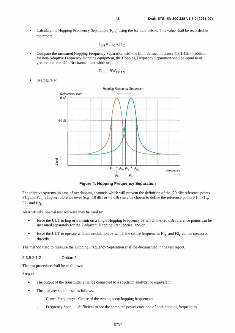
ETSI
Draft ETSI EN 300 328 V1.8.0 (2011-07) 43
• Calculate the Hopping Frequency Separation (FHS) using the formula below. This value shall be recorded in
the report.
FHS = F2C - F1C
• Compare the measured Hopping Frequency Separation with the limit defined in clause 4.3.1.4.2. In addition, for non-Adaptive Frequency Hopping equipment, the Hopping Frequency Separation shall be equal to or greater than the -20 dBr channel bandwidth or:
FHS ≥ BWCHAN
• See figure 4:
Figure 4: Hopping Frequency Separation
For adaptive systems, in case of overlapping channels which will prevent the definition of the -20 dBr reference points F1H and F2L, a higher reference level (e.g. -10 dBr or - 6 dBr) may be chosen to define the reference points F1L; F1H;
F2L and F2H.
Alternatively, special test software may be used to:
• force the UUT to hop or transmit on a single Hopping Frequency by which the -20 dBr reference points can be measured separately for the 2 adjacent Hopping Frequencies; and/or
• force the UUT to operate without modulation by which the centre frequencies F1C and F2C can be measured
directly.
The method used to measure the Hopping Frequency Separation shall be documented in the test report.
5.3.5.2.1.2 Option 2
The test procedure shall be as follows:
Step 1:
• The output of the transmitter shall be connected to a spectrum analyzer or equivalent.
• The analyzer shall be set as follows:
- Centre Frequency: Centre of the two adjacent hopping frequencies
- Frequency Span: Sufficient to see the complete power envelope of both hopping frequencies

ETSI
Draft ETSI EN 300 328 V1.8.0 (2011-07) 44
- RBW: 1 % of the Span
- VBW: 3 × RBW
- Detector Mode: RMS
- Trace Mode: Max Hold
- Sweep Time: Auto
Step 2:
• Allow the trace to stabilize
• Use the marker-delta function to determine the Hopping Frequency Separation between the peaks of the two adjacent hopping frequencies. This value shall be compared with the limits defined in clause 4.3.1.4.2 and shall be recorded in the test report.
5.3.5.2.2 Radiated measurements
This method shall only be used for integral antenna equipment that does not have a temporary antenna connector(s) provided.
A test site as described in annex B and applicable measurement procedures as described in annex C may be used. Alternatively a test fixture may be used.
The test procedure is further as described under clause 5.3.5.2.1.
5.3.6 Void
5.3.7 Adaptivity (Channel access mechanism)
5.3.7.1 Test conditions
See clause 5.1 for the test conditions. These measurements shall only be performed at normal test conditions.
This test shall be performed on the lowest and the highest operating (hopping) frequency. For adaptive frequency hopping equipment, the equipment shall be in a normal operating (hopping) mode.
For equipment which can operate in an adaptive and a non-adaptive mode, it shall be verified that prior to the test, the equipment is operating in the adaptive mode.
5.3.7.2 Test Method
5.3.7.2.1 Conducted measurements
Figure 5 describes an example of the test set-up.

ETSI
Draft ETSI EN 300 328 V1.8.0 (2011-07) 45
Figure 5: Test Set-up for verifying the adaptivity of an equipment
5.3.7.2.1.1 Adaptive Frequency Hopping equipment using DAA
The different steps below define the procedure to verify the efficiency of the DAA based adaptive mechanisms for frequency hopping equipment. These mechanisms are described in clause 4.3.1.6.
Step 1:
• The UUT may connect to a companion device during the test. The interference signal generator, the blocking signal generator, the spectrum analyser, the UUT and the companion device are connected using a set-up equivalent to the example given by figure 5, although the interference and blocking signal generators do not generate any signals at this point in time. The spectrum analyser is used to monitor the transmissions of the UUT in response to the interfering and the blocking signals.
• For the hopping frequency to be tested, adjust the received signal level (wanted signal from the companion device) at the UUT to the value defined in table 3 (clause 4).
NOTE 1: Testing of Unidirectional equipment does not require a link to be established with a companion device.
• The analyzer shall be set as follows:
RBW: ≥ Occupied Channel Bandwidth (use next available RBW setting above the Occupied Channel Bandwidth)
Filter type: Channel Filter
VBW: 3 × RBW
Detector Mode: RMS
Centre Frequency: Equal to the hopping frequency to be tested
Span: 0 Hz
Sweep time: > Channel Occupancy Time of the UUT. If the Channel Occupancy Time is non- contiguous (non-LBT based equipment), the sweep time shall be sufficient to cover the period over which the Channel Occupancy Time is spread out.
Trace Mode: Clear/Write
Trigger Mode: Video
ETSI
Draft ETSI EN 300 328 V1.8.0 (2011-07) 46
Step 2:
• Configure the UUT for normal transmissions with a sufficiently high payload to allow demonstration of compliance of the adaptive mechanism on the hopping frequency being tested.
• Using the procedure defined in clause 5.3.7.2.1.4, it shall be verified that, for systems with a dwell time greater than the maximum allowable Channel Occupancy Time, the UUT complies with the maximum Channel Occupancy Time and minimum Idle period defined in clauses 4.3.1.6.1.2 and 4.3.1.6.2.2.
Step 3: Adding the interference signal
• A 100 % duty cycle interference signal is injected centred on the hopping frequency being tested. This interference signal shall be a band limited noise signal which has a flat power density, and shall have a bandwidth greater than the Occupied Channel Bandwidth of the UUT. The maximum ripple of this interfering signal shall be ± 1,5 dB within the Occupied Channel Bandwidth and the power density (at the input of the UUT) shall be as defined in clauses 4.3.1.6.1.2 or 4.3.1.6.2.2.
Step 4: Verification of reaction to the interference signal
• The spectrum analyser shall be used to monitor the transmissions of the UUT on the selected hopping frequency with the interfering signal injected. This may require the spectrum analyser sweep to be triggered by the start of the interfering signal.
• Using the procedure defined in clause 5.3.7.2.1.4, it shall be verified that:
i) The UUT shall stop transmissions on the hopping frequency being tested.
NOTE 2: The UUT is assumed to stop transmissions on this hopping frequency within a period equal to the maximum Channel Occupancy Time defined in clauses 4.3.1.6.1 or 4.3.1.6.2. As stated in clause 4.3.1.6.2.2, the Channel Occupancy Time for non-LBT based frequency hopping systems may be non-contiguous.
ii) For LBT based frequency hopping equipment, apart from Short Control Signalling Transmissions (see iii) below), there shall be no subsequent transmissions on this hopping frequency, as long as the interference signal remains present.
For non-LBT based frequency hopping equipment, apart from Short Control Signalling Transmissions (see iii) below), there shall be no subsequent transmissions on this hopping frequency for a (silent) period defined in clause 4.3.1.6.2.2 step 3. After that, the UUT may have normal transmissions again for the duration of a single Channel Occupancy Time period (which may be non-contiguous). Because the interference signal is still present, another silent period as defined in clause 4.3.1.6.2.2 step 3 needs to be included. This sequence is repeated as long as the interfering signal is present .
NOTE 3: In case of overlapping channels, transmissions in adjacent channels may generate transmission bursts on the channel being investigated, however they will have a lower amplitude as on-channel transmissions. Care should be taken to only evaluate the on-channel transmissions. The Time Domain Power Option of the analyser may be used to measure the RMS power of the individual bursts to distinguish on-channel transmissions from transmissions on adjacent channels. In some cases, the RBW may need to be reduced.
iii) The UUT may continue to have Short Control Signalling Transmissions on the hopping frequency being tested while the interference signal is present. These transmissions shall comply with the limits defined in clause 4.3.1.6.3.2.
NOTE 4: The verification of the Short Control Signalling transmissions may require the analyser settings to be changed (e.g. sweep time).
iv) Alternatively, the equipment may switch to a non-adaptive mode.
Step 5: Adding the blocking signal
• With the interfering signal present, a 100 % duty cycle CW signal is inserted as the blocking signal. The frequency and the level are provided in table 3 of clause 4.3.1.10.2.
• Repeat step 4 to verify that the UUT does not resume any normal transmissions on the hopping frequency being investigated.

ETSI
Draft ETSI EN 300 328 V1.8.0 (2011-07) 47
Step 6: Removing the interference and blocking signal
• On removal of the interference and blocking signal, the UUT is allowed to re-include any channel previously marked as unavailable; however, for non-LBT based systems, it shall be verified that this shall only be done after the period defined in clause 4.3.1.6.2.2 point 3.
Step 7:
• The steps 2 to 6 shall be repeated for each of the hopping frequencies to be tested.
5.3.7.2.1.2 Non-LBT based Adaptive equipment using modulations other than FHSS
The different steps below define the procedure to verify the efficiency of the non-LBT based DAA adaptive mechanism of equipment using wide band modulations other than FHSS.
Step 1:
• The UUT may connect to a companion device during the test. The interference signal generator, the blocking signal generator, the spectrum analyser, the UUT and the companion device are connected using a set-up equivalent to the example given by figure 5 although the interference and blocking signal generator do not generate any signals at this point in time. The spectrum analyser is used to monitor the transmissions of the UUT in response to the interfering and the blocking signals.
• Adjust the received signal level (wanted signal from the companion device) at the UUT to the value defined in table 6 (clause 4).
NOTE 1: Testing of Unidirectional equipment does not require a link to be established with a companion device.
• The analyzer shall be set as follows:
RBW : ≥ Occupied Channel Bandwidth (use next available RBW setting above the Occupied Channel Bandwidth)
VBW : 3 × RBW
Detector Mode: RMS
Centre Frequency: Equal to the centre frequency of the operating channel
Span: 0 Hz
Sweep time: > Channel Occupancy Time of the UUT
Trace Mode: Clear/Write
Trigger Mode: Video
Step 2:
• Configure the UUT for normal transmissions with a sufficiently high payload to allow demonstration of compliance of the adaptive mechanism on the channel being tested.
• Using the procedure defined in clause 5.3.7.2.1.4, it shall be verified that the UUT complies with the maximum Channel Occupancy Time and minimum Idle period defined in clause 4.3.2.5.1.2.
Step 3: Adding the interference signal
• A 100 % duty cycle interference signal is injected on the current operating channel of the UUT. This interference signal shall be a band limited noise signal which has a flat power density, and shall have a bandwidth greater than the Occupied Channel Bandwidth of the UUT. The maximum ripple of this interfering signal shall be ± 1,5 dB within the Occupied Channel Bandwidth and the power density (at the input of the UUT) shall be as defined in clause 4.3.2.5.1.2.

ETSI
Draft ETSI EN 300 328 V1.8.0 (2011-07) 48
Step 4: Verification of reaction to the interference signal
• The spectrum analyser shall be used to monitor the transmissions of the UUT on the selected operating channel with the interfering signal injected. This may require the spectrum analyser sweep to be triggered by the start of the interfering signal.
• Using the procedure defined in clause 5.3.7.2.1.4, it shall be verified that:
i) The UUT shall stop transmissions on the current operating channel being tested.
NOTE 2: The UUT is assumed to stop transmissions within a period equal to the maximum Channel Occupancy Time defined in clause 4.3.2.5.1.2 step 3.
ii) Apart from Short Control Signalling Transmissions (see iii) below), there shall be no subsequent transmissions on this operating channel for a (silent) period defined in clause 4.3.2.5.1.2 step 2. After that, the UUT may have normal transmissions again for the duration of a single Channel Occupancy Time period. Because the interference signal is still present, another silent period as defined in clause 4.3.2.5.1.2 step 2 needs to be included. This sequence is repeated as long as the interfering signal is present.
iii) The UUT may continue to have Short Control Signalling Transmissions on the operating channel while the interference signal is present. These transmissions shall comply with the limits defined in clause 4.3.2.5.3.2.
NOTE 3: The verification of the Short Control Signalling transmissions may require the analyser settings to be changed (e.g. sweep time).
iv) Alternatively, the equipment may switch to a non-adaptive mode.
Step 5: Adding the blocking signal
• With the interfering signal present, a 100 % duty cycle CW signal is inserted as the blocking signal. The frequency and the level are provided in table 6 of clause 4.3.2.10.2.
• Repeat step 4 to verify that the UUT does not resume any normal transmissions.
Step 6: Removing the interference and blocking signal
• On removal of the interference and blocking signal the UUT is allowed to start transmissions again on this channel however, it shall be verified that this shall only be done after the period defined in clause 4.3.2.5.1.2 step 2.
Step 7:
• The steps 2 to 6 shall be repeated for each of the frequencies to be tested.
5.3.7.2.1.3 LBT based adaptive equipment using modulations other than FHSS
The different steps below define the procedure to verify the efficiency of the LBT based adaptive mechanism of equipment using wide band modulations other than FHSS. This method can be applied on Load Based Equipment and Frame Based Equipment.
Step 1:
• The UUT may connect to a companion device during the test. The interference signal generator, the blocking signal generator, the spectrum analyser, the UUT and the companion device are connected using a set-up equivalent to the example given by figure 5 although the interference and blocking signal generator do not generate any signals at this point in time. The spectrum analyser is used to monitor the transmissions of the UUT in response to the interfering and the blocking signals.
• Adjust the received signal level (wanted signal from the companion device) at the UUT to the value defined in table 6 (clause 4).
NOTE 1: Testing of Unidirectional equipment does not require a link to be established with a companion device.

ETSI
Draft ETSI EN 300 328 V1.8.0 (2011-07) 49
• The analyzer shall be set as follows:
- RBW : ≥ Occupied Channel Bandwidth (use next available RBW setting above the Occupied Channel Bandwidth)
- VBW : 3 × RBW
- Detector Mode: RMS
- Centre Frequency: Equal to the centre frequency of the operating channel
- Span: 0 Hz
- Sweep time: > 1 Fixed Frame Period (Frame Based Equipment) or > maximum Channel Occupancy Time (Load Based Equipment)
- Trace Mode: Clear Write
- Trigger Mode: Video
Step 2:
• Configure the UUT for normal transmissions with a sufficiently high payload to allow demonstration of compliance of the adaptive mechanism on the channel being tested.
• Using the procedure defined in clause 5.3.7.2.1.4, it shall be verified that the UUT complies with the maximum Channel Occupancy Time and minimum Idle period defined in clauses 4.3.2.5.2.2.1 (frame based equipment) or 4.3.2.5.2.2.2 (load based equipment).
Step 3: Adding the interference signal
• A 100 % duty cycle interference signal is injected on the current operating channel of the UUT. This interference signal shall be a band limited noise signal which has a flat power density, and shall have a bandwidth greater than the Occupied Channel Bandwidth of the UUT. The maximum ripple of this interfering signal shall be ±1,5 dB within the Occupied Channel Bandwidth and the power density (at the input of the UUT) shall be as defined in clause 4.3.2.5.2.2.1 step 5 (frame based equipment) or clause 4.3.2.5.2.2.2 step 5 (load based equipment).
Step 4: Verification of reaction to the interference signal
• The spectrum analyser shall be used to monitor the transmissions of the UUT on the selected operating channel with the interfering signal injected. This may require the spectrum analyser sweep to be triggered by the start of the interfering signal.
• Using the procedure defined in clause 5.3.7.2.1.4, it shall be verified that:
i) The UUT shall stop transmissions on the current operating channel.
NOTE 2: The UUT is assumed to stop transmissions within a period equal to the maximum Channel Occupancy Time defined in clauses 4.3.2.5.2.2.1 (frame based equipment) or 4.3.2.5.2.2.2 (load based equipment).
ii) Apart from Short Control Signalling Transmissions, there shall be no subsequent transmissions while the interfering signal is present.
iii) The UUT may continue to have Short Control Signalling Transmissions on the operating channel while the interfering signal is present. These transmissions shall comply with the limits defined in clause 4.3.2.5.3.2.
NOTE 3: The verification of the Short Control Signalling transmissions may require the analyser settings to be changed (e.g. sweep time).
iv) Alternatively, the equipment may switch to a non-adaptive mode.

ETSI
Draft ETSI EN 300 328 V1.8.0 (2011-07) 50
Step 5: Adding the blocking signal
• With the interfering signal present, a 100 % duty cycle CW signal is inserted as the blocking signal. The frequency and the level are provided in table 6 of clause 4.3.2.10.2.
• Repeat step 4 to verify that the UUT does not resume any normal transmissions.
Step 6: Removing the interference and blocking signal
• On removal of the interference and blocking signal the UUT is allowed to start transmissions again on this channel however this is not a requirement and therefore does not require testing.
Step 7:
• The steps 2 to 6 shall be repeated for each of the frequencies to be tested.
5.3.7.2.1.4 Generic test procedure for measuring channel/frequency usage
This is a generic test method to evaluate transmissions on the operating (hopping) frequency being investigated. This test is performed as part of the procedures described in clause 5.3.7.2.1.1 up to clause 5.3.7.2.1.3.
The test procedure shall be as follows:
Step 1:
• The analyzer shall be set as follows:
- Centre Frequency: equal to the hopping frequency or centre frequency of the channel being investigated
- Frequency Span: 0 Hz
- RBW: ~ 50 % of the Occupied Channel Bandwidth
- VBW: 3 × RBW
- Detector Mode: RMS
- Sweep time: > the Channel Occupancy Time. It shall be noted that if the Channel Occupancy Time is non-contiguous (for non-LBT based Frequency Hopping Systems), the sweep time shall be sufficient to cover the period over which the Channel Occupancy Time is spread out.
- Number of sweep points: see note
NOTE: The time resolution has to be sufficient to meet the maximum measurement uncertainty of 5 % for the period to be measured. In most cases, the Idle Period is the shortest period to be measured and thereby defining the time resolution. If the Channel Occupancy Time is non-contiguous (non-LBT based Frequency Hopping Systems), there is no Idle Period to be measured and therefore the time resolution can be increased (e.g. to 5 % of the dwell time) to cover the period over which the Channel Occupancy Time is spread out, without resulting in too high a number of sweep points for the analyzer.
EXAMPLE 1: For a Channel Occupancy Time of 60 ms, the minimum Idle Period is 3 ms, hence the minimum time resolution should be < 150 µs.
EXAMPLE 2: For a Channel Occupancy Time of 2 ms, the minimum Idle Period is 100 µs, hence the minimum time resolution should be < 5 µs.
EXAMPLE 3: In case of a system using the non-contiguous Channel Occupancy Time approach (40 ms) and using 79 hopping frequencies with a dwell time of 3,75 ms, the total period over which the Channel Occupancy Time is spread out is 3,2 s. With a time resolution 0,1875 ms (5 % of the dwell time), the minimum number of sweep points is ~ 17 000.
- Trace mode: Clear / Write
- Trigger: Video

ETSI
Draft ETSI EN 300 328 V1.8.0 (2011-07) 51
In case of Frequency Hopping Equipment, the data points resulting from transmissions on the hopping frequency being investigated are assumed to have much higher levels compared to data points resulting from transmissions on adjacent hopping frequencies. If a clear determination between these transmissions is not possible, the RBW in step 1 shall be further reduced. In addition, a channel filter may be used.
Step 2:
• Save the trace data to a file for further analysis by a computing device using an appropriate software application or program.
Step 3:
• Indentify the data points related to the frequency being investigated by applying a threshold.
• Count the number of consecutive data points identified as resulting from a single transmission on the frequency being investigated and multiply this number by the time difference between two consecutive data points.
• Repeat this for all the transmissions within the measurement window.
• For measuring idle or silent periods, count the number of consecutive data points identified as resulting from a single transmitter off period on the frequency being investigated and multiply this number by the time difference between two consecutive data points.
• Repeat this for all the transmitter off periods within the measurement window.
5.3.7.2.2 Radiated measurements
This method shall only be used for integral antenna equipment that does not have a temporary antenna connector(s) provided.
A test site as described in annex B and applicable measurement procedures as described in annex C shall be used.
The test procedure is further as described under clauses 5.3.7.2.1.
5.3.8 Occupied Channel Bandwidth
5.3.8.1 Test conditions
See clause 5.1 for the test conditions. These measurements shall only be performed at normal test conditions.
In case of conducted measurements on smart antenna systems (equipment with multiple transmit chains) measurements need only to be performed on one of the active transmit chains (antenna outputs).
For systems using FHSS modulation and which have overlapping channels, special software might be required to force the UUT to hop or transmit on a single Hopping Frequency.
The measurement shall be performed only on the lowest and the highest frequency within the stated frequency range. The frequencies on which the test were performed shall be recorded.
If the equipment can operate with different Occupied Channel Bandwidths (e.g. 20 MHz and 40 MHz), than each channel bandwidth shall be tested separately.
ETSI
Draft ETSI EN 300 328 V1.8.0 (2011-07) 52
5.3.8.2 Test method
5.3.8.2.1 Conducted measurement
The measurement procedure shall be as follows:
Step 1:
Connect the UUT to the spectrum analyser and use the following settings:
• Centre Frequency: The centre frequency of the channel under test
• Resolution BW: Auto
• Video BW: Auto
• Frequency Span: 2 × Occupied Channel Bandwidth (e.g. 40 MHz for a 20 MHz channel)
• Detector Mode: RMS
• Trace Mode: Max Hold
Step 2:
Wait until the trace is completed.
Find the peak value of the trace and place the analyser marker on this peak.
Step 3:
Use the 99 % bandwidth function of the spectrum analyser to measure the Occupied Channel Bandwidth of the UUT. This value shall be recorded.
NOTE: Make sure that the power envelope is sufficiently above the noise floor of the analyser to avoid the noise signals left and right from the power envelope being taken into account by this measurement.
5.3.8.2.2 Radiated measurement
This method shall only be used for integral antenna equipment that does not have a temporary antenna connector(s) provided.
The test set up as described in annex B and the applicable measurement procedures described in annex C shall be used. Alternatively a test fixture may be used.
The test procedure is as described under clause 5.3.8.2.1.
5.3.9 Transmitter unwanted emissions in the out-of-band domain
5.3.9.1 Test conditions
See clause 5.1 for the test conditions. These measurements have to be performed at normal environmental conditions and shall be repeated at the extremes of the operating temperature range.
In the case of equipment intended for use with an integral antenna and where no external (temporary) antenna connectors are provided, a test fixture as described in clause C.1 may be used to perform relative measurements at the extremes of the operating temperature range.
For systems using FHSS modulation, the measurements shall be performed during normal operation (hopping).
For systems using wide band modulations other than FHSS, the measurement shall be performed at the lowest and the highest channel on which the equipment can operate. These frequencies shall be recorded.
The equipment shall be configured to operate under its worst case situation with respect to output power.

ETSI
Draft ETSI EN 300 328 V1.8.0 (2011-07) 53
If the equipment can operate with different Occupied Channel Bandwidths (e.g. 20 MHz and 40 MHz), than each channel bandwidth shall be tested separately.
5.3.9.2 Test method
5.3.9.2.1 Conducted measurement
The applicable mask is defined by the measurement results from the tests performed under clause 5.3.8. (Occupied Channel Bandwidth).
The Out-of-band emissions within the different horizontal segments of the mask provided in figures 1 and 3 shall be measured using the steps below. This method assumes the spectrum analyser is equipped with the Time Domain Power option.
Step 1:
• Connect the UUT to the spectrum analyser and use the following settings:
- Centre Frequency: 2 484 MHz
- Span: 0 Hz
- Resolution BW: 1 MHz
- Filter mode: Channel filter
- Video BW: 3 MHz
- Detector Mode: RMS
- Trace Mode: Clear / Write
- Sweep Mode: Continuous
- Sweep Points: 5 000
- Trigger Mode: Video trigger
- Sweep Time: Suitable to capture one transmission burst
Step 2: (segment 2 483,5 MHz to 2 483,5 MHz + BW)
• Adjust the trigger level to select the transmissions with the highest power level.
For frequency hopping equipment operating in a normal hopping mode, the different hops will result in signals bursts with different power levels. In this case the burst with the highest power level shall be selected.
• Set a window (start and stop lines) to match with the start and end of the burst and in which the RMS power shall be measured using the Time Domain Power function.
• Select RMS power to be measured within the selected window and note the result which is the RMS power within this 1 MHz segment (2 483,5 MHz to 2 484,5 MHz). Compare this value with the applicable limit provided by the mask.
• Increase the centre frequency in steps of 1 MHz and repeat this measurement for every 1 MHz segment within the range 2 483,5 MHz to 2 483,5 MHz + BW. The centre frequency of the last 1 MHz segment shall be set to 2 483,5 MHz + BW - 0,5 MHz (which means this may partly overlap with the previous 1 MHz segment).
Step 3: (segment 2 483,5 MHz + BW to 2 483,5 MHz + 2BW)
• Change the centre frequency of the analyser to 2 484 MHz + BW and perform the measurement for the first 1 MHz segment within range 2 483,5 MHz + BW to 2 483,5 MHz + 2BW. Increase the centre frequency in 1 MHz steps and repeat the measurements to cover this whole range. The centre frequency of the last 1 MHz segment shall be set to 2 483,5 MHz + 2 BW - 0,5 MHz.

ETSI
Draft ETSI EN 300 328 V1.8.0 (2011-07) 54
Step 4: (segment 2 400 MHz - BW to 2 400 MHz)
• Change the centre frequency of the analyser to 2 399,5 MHz and perform the measurement for the first 1 MHz segment within range 2 400 MHz - BW to 2 400 MHz Reduce the centre frequency in 1 MHz steps and repeat the measurements to cover this whole range. The centre frequency of the last 1 MHz segment shall be set to 2 400 MHz - 2BW + 0,5 MHz.
Step 5: (segment 2 400 MHz - 2BW to 2 400 MHz - BW)
• Change the centre frequency of the analyser to 2 399,5 MHz - BW and perform the measurement for the first 1 MHz segment within range 2 400 MHz - 2BW to 2 400 MHz - BW. Reduce the centre frequency in 1 MHz steps and repeat the measurements to cover this whole range. The centre frequency of the last 1 MHz segment shall be set to 2 400 MHz - 2BW + 0,5 MHz.
Step 6:
• In case of conducted measurements on smart antenna systems (equipment with multiple transmit chains), the measurements need to be repeated for each of the active transmit chains. Comparison with the applicable limits shall be done using any of the options given below:
- Option 1: the results for each of the transmit chains for the corresponding 1 MHz segments shall be added and compared with the limits provided by the mask given in figures 1 or 3.
- Option 2: the results for each of the transmit chains shall be individually compared with the limits provided by the mask given in figures 1 or 3 after that these limits have been reduced with 10 x log10
(Ach) (number of active transmit chains)
It shall be recorded whether the equipment complies with the mask provided in figures 1 or 3.
5.3.9.2.2 Radiated measurement
This method shall only be used for integral antenna equipment that does not have a temporary antenna connector(s) provided.
The test set up as described in annex B and the applicable measurement procedures described in annex C shall be used. Alternatively a test fixture may be used.
The test procedure is as described under clause 5.3.9.2.1.
5.3.10 Transmitter unwanted emissions in the spurious domain
5.3.10.1 Test conditions
See clause 5.1 for the test conditions. These measurements shall only be performed at normal test conditions.
For systems using FHSS modulation, the measurements may be performed when normal hopping is disabled. In this case measurements need to be performed when operating at the lowest and the highest hopping frequency. When this is not possible, the measurement shall be performed during normal operation (hopping).
For systems using wide band modulations other than FHSS, the measurement shall be performed at the lowest and the highest channel on which the equipment can operate. These frequencies shall be recorded.
The equipment shall be configured to operate under its worst case situation with respect to output power.
If the equipment can operate with different Occupied Channel Bandwidths (e.g. 20 MHz and 40 MHz), then the equipment shall be configured to operate under its worst case situation with respect to spurious emissions.

ETSI
Draft ETSI EN 300 328 V1.8.0 (2011-07) 55
5.3.10.2 Test method
5.3.10.2.1 Conducted measurement
In case of conducted measurements, the radio equipment shall be connected to the measuring equipment via a suitable attenuator.
The spectrum in the spurious domain (see figures 1 or 3) shall be searched for emissions that exceed the limit values given in tables 1 or 4 or that come to within 6 dB below these limits. Each occurrence shall be recorded.
The measurement procedure shall be as follows.
5.3.10.2.1.1 Pre-scan
The test procedure below shall be used to identify potential unwanted emissions of the UUT.
Step 1:
The sensitivity of the spectrum analyser should be such that the noise floor is at least 12 dB below the limits given in tables 1 or 4.
Step 2:
The emissions over the range 30 MHz to 1 000 MHz shall be identified.
Spectrum analyser settings:
• Resolution bandwidth: 100 kHz
• Video bandwidth: 300 kHz
• Detector mode: Peak
• Trace Mode: Max Hold
• Sweep Points: ≥ 9 970
NOTE 1: For spectrum analysers not supporting this high number of sweep points, the frequency band may need to be segmented.
• Sweep time: For non continuous transmissions (duty cycle less than 100 %), the sweep time shall be sufficiently long, such that for each 100 kHz frequency step, the measurement time is greater than two transmissions of the UUT.
For Frequency Hopping equipment operating in a normal operating (hopping not disabled) mode, the sweep time shall be further increased to capture multiple transmissions on the same hopping frequency in different hopping sequences.
Allow the trace to stabilize. Any emissions identified during the sweeps above and that fall within the 6 dB range below the applicable limit or above, shall be individually measured using the procedure in clause 5.3.10.2.1.2 and compared to the limits given in tables 1 or 4.
Step 3:
The emissions over the range 1 GHz to 12,75 GHz shall be identified.
Spectrum analyser settings:
• Resolution bandwidth: 1 MHz
• Video bandwidth: 3 MHz
• Detector mode: Peak
• Trace Mode: Max Hold
ETSI
Draft ETSI EN 300 328 V1.8.0 (2011-07) 56
• Sweep Points: ≥ 11 750
NOTE 2: For spectrum analysers not supporting this high number of sweep points, the frequency band may need to be segmented.
• Sweep time: For non continuous transmissions (duty cycle less than 100 %), the sweep time shall be sufficiently long, such that for each 1 MHz frequency step, the measurement time is greater than two transmissions of the UUT.
For Frequency Hopping equipment operating in a normal operating (hopping not disabled) mode, the sweep time shall be further increased to capture multiple transmissions on the same hopping frequency in different hopping sequences.
Allow the trace to stabilize. Any emissions identified during the sweeps above that fall within the 6 dB range below the applicable limit or above, shall be individually measured using the procedure in clause 5.3.10.2.1.2 and compared to the limits given in tables 1 or 4.
Frequency Hopping equipment may generate a block (or several blocks) of spurious emissions anywhere within the spurious domain. If this is the case, only the highest peak of each block of emissions shall be measured using the procedure in clause 5.3.10.2.1.2.
Step 4:
• In case of conducted measurements on smart antenna systems (equipment with multiple transmit chains), the steps 2 and 3 need to be repeated for each of the active transmit chains (Ach)The limits used to identify
emissions during this pre-scan need to be reduced with 10 × log10 (Ach) (number of active transmit chains).
5.3.10.2.1.2 Measurement of the emissions identified during the pre-scan
The steps below shall be used to accurately measure the individual unwanted emissions identified during the pre-scan measurements above.
Step 1:
The level of the emissions shall be measured using the following spectrum analyser settings:
• Centre Frequency: Frequency of emission identified during the pre-scan
• Resolution Bandwidth: 100 kHz (< 1 GHz) / 1 MHz (> 1 GHz)
• Video Bandwidth: 300 kHz (< 1 GHz) / 3 MHz (> 1 GHz)
• Frequency Span: Wide enough to capture each individual emission indentified during the pre-scan
• Sweep mode: Continuous
• Sweep time: Auto
• Trigger: Free run
• Detector: RMS
• Trace Mode: Max Hold
Step 2:
In case of conducted measurements on smart antenna systems (equipment with multiple transmit chains), the step 1 needs to be repeated for each of the active transmit chains (Ach).
The trace data for each transmit chain has to be recorded.
Sum the power in each of the traces for each individual frequency bin.
Step 3:

ETSI
Draft ETSI EN 300 328 V1.8.0 (2011-07) 57
Use the marker function to find the highest peak within the measurement trace and record its value and its frequency.
Step 4:
The measured values shall be compared to the limits defined in tables 1 and 4.
5.3.10.2.2 Radiated measurement
The test site as described in annex B and applicable measurement procedures as described in annex C shall be used.
The test procedure is further as described under clause 5.3.10.2.1.
5.3.11 Receiver spurious emissions
5.3.11.1 Test conditions
See clause 5.3 for the test conditions. These measurements shall only be performed at normal test conditions.
The level of spurious emissions shall be measured as, either:
a) their power in a specified load (conducted spurious emissions) and their effective radiated power when radiated by the cabinet or structure of the equipment (cabinet radiation); or
b) their effective radiated power when radiated by cabinet and antenna.
Testing shall be performed when the equipment is in a receive-only mode.
For systems using wide band modulations other than FHSS, the measurement shall be performed at the lowest and the highest channel on which the equipment can operate. These frequencies shall be recorded.
For systems using FHSS modulation, the measurements may be performed when normal hopping is disabled. In this case measurements need to be performed when operating at the lowest and the highest hopping frequency. These frequencies shall be recorded. When disabling the normal hopping is not possible, the measurement shall be performed during normal operation (hopping).
5.3.11.2 Test method
5.3.11.2.1 Conducted measurement
In case of conducted measurements, the radio equipment shall be connected to the measuring equipment via a suitable attenuator.
The spectrum in the spurious domain (see figures 1 or 3) shall be searched for emissions that exceed the limit values given in tables 2 or 5 or that come to within 6 dB below these limits. Each occurrence shall be recorded.
The measurement procedure shall be as follows.
5.3.11.2.1.1 Pre-scan
The test procedure below shall be used to identify potential unwanted emissions of the UUT.
Step 1:
The sensitivity of the spectrum analyser should be such that the noise floor is at least 12 dB below the limits given in tables 2 or 5.
Step 2:
The emissions over the range 30 MHz to 1 000 MHz shall be identified.
Spectrum analyser settings:
• Resolution bandwidth: 100 kHz

ETSI
Draft ETSI EN 300 328 V1.8.0 (2011-07) 58
• Video bandwidth: 300 kHz
• Detector mode: Peak
• Trace Mode: Max Hold
• Sweep Points: ≥ 9 970
• Sweep time: Auto
Allow the trace to stabilize. Any emissions identified during the sweeps above and that fall within the 6 dB range below the applicable limit or above, shall be individually measured using the procedure in clause 5.3.11.2.1.2 and compared to the limits given in tables 2 or 5.
Step 3:
The emissions over the range 1 GHz to 12,75 GHz shall be identified.
Spectrum analyser settings:
• Resolution bandwidth: 1 MHz
• Video bandwidth: 3 MHz
• Detector mode: Peak
• Trace Mode: Max Hold
• Sweep Points: ≥ 11 750
• Sweep time: Auto
Allow the trace to stabilize. Any emissions identified during the sweeps above that fall within the 6 dB range below the applicable limit or above, shall be individually measured using the procedure in clause 5.3.11.2.1.2 and compared to the limits given in tables 2 or 5.
Frequency Hopping equipment may generate a block (or several blocks) of spurious emissions anywhere within the spurious domain. If this is the case, only the highest peak of each block of emissions shall be measured using the procedure in clause 5.3.11.2.1.2.
Step 4:
• In case of conducted measurements on smart antenna systems (equipment with multiple receive chains), the steps 2 and 3 need to be repeated for each of the active receive chains (Ach).
• The limits used to identify emissions during this pre-scan need to be reduced with 10 × log10 (Ach) (number of
active receive chains).
5.3.11.2.1.2 Measurement of the emissions identified during the pre-scan
The steps below shall be used to accurately measure the individual unwanted emissions identified during the pre-scan measurements above.
Step 1:
The level of the emissions shall be measured using the following spectrum analyser settings:
• Centre Frequency: Frequency of emission identified during the pre-scan
• Resolution Bandwidth: 100 kHz (< 1 GHz) / 1 MHz (> 1 GHz)
• Video Bandwidth: 300 kHz (< 1 GHz) / 3 MHz (> 1 GHz)
• Frequency Span: Wide enough to capture each individual emission indentified during the pre-scan
• Sweep mode: Continuous

ETSI
Draft ETSI EN 300 328 V1.8.0 (2011-07) 59
• Sweep time: Auto
• Trigger: Free run
• Detector: RMS
• Trace Mode: Max Hold
Step 2:
In case of conducted measurements on smart antenna systems (equipment with multiple receive chains), the step 1 needs to be repeated for each of the active receive chains (Ach).
The trace data for each receive chain has to be recorded.
Sum the power in each of the traces for each individual frequency bin.
Step 3:
Use the marker function to find the highest peak within the measurement trace and record its value and its frequency.
Step 4:
The measured values shall be compared to the limits defined in tables 2 and 5.
5.3.11.2.2 Radiated measurement
The test site as described in annex B and applicable measurement procedures as described in annex C shall be used.
The test procedure is further as described under clause 5.3.11.2.1.

ETSI
Draft ETSI EN 300 328 V1.8.0 (2011-07) 60
Annex A (normative): HS Requirement and conformance Test specifications Table (HS-RTT) The HS Requirements and conformance Test specifications Table (HS-RTT) in table A.1 serves a number of purposes, as follows:
• it provides a statement of all the requirements in words and by cross reference to (a) specific clause(s) in the present document or to (a) specific clause(s) in (a) specific referenced document(s);
• it provides a statement of all the test procedures corresponding to those requirements by cross reference to (a) specific clause(s) in the present document or to (a) specific clause(s) in (a) specific referenced document(s);
• it qualifies each requirement to be either:
- Unconditional: meaning that the requirement applies in all circumstances, or
- Conditional: meaning that the requirement is dependant on the manufacturer having chosen to support optional functionality defined within the schedule.
• in the case of Conditional requirements, it associates the requirement with the particular optional service or functionality;
• it qualifies each test procedure to be either:
- Essential: meaning that it is included with the Essential Radio Test Suite and therefore the requirement shall be demonstrated to be met in accordance with the referenced procedures;
- Other: meaning that the test procedure is illustrative but other means of demonstrating compliance with the requirement are permitted.

ETSI
Draft ETSI EN 300 328 V1.8.0 (2011-07) 61
Table A.1: HS Requirements and conformance Test specifications Table (HS-RTT)
Harmonized Standard EN 300 328 The following requirements and test specifications are relevant to the presumption of conformity
under the article 3.2 of the R&TTE Directive [i.1] Requirement Requirement Conditionality Test Specification
No Description Reference: Clause No U/C Condition E/O Reference:
Clause No 1 RF Output Power 4.3.1.1 or
4.3.2.1 U E 5.3.2
2 Power Density 4.3.2.2 C Only for modulations other than FHSS
E 5.3.3
3 Duty cycle, Tx-Sequence, Tx-gap 4.3.1.2 or 4.3.2.3
C Only for non-adaptive equipment
E 5.3.2
4 Dwell time, Minimum Frequency Occupation & Hopping Sequence
4.3.1.3 C Only for FHSS E 5.3.4
5 Hopping Frequency Separation 4.3.1.4 C Only for FHSS E 5.3.5 6 Medium Utilisation 4.3.1.5 or
4.3.2.4 C Only for non-adaptive
equipment E 5.3.2
7 Adaptivity 4.3.1.6 or 4.3.2.5
C Only for adaptive equipment
E 5.3.7
8 Occupied Channel Bandwidth 4.3.1.7 or 4.3.2.6
U E 5.3.8
9 Transmitter unwanted emissions in the OOB domain
4.3.1.8 or 4.3.2.7
U E 5.3.9
10 Transmitter unwanted emissions in the spurious domain
4.3.1.9 or 4.3.2.8
U E 5.3.10
11 Receiver spurious emissions 4.3.1.10 or 4.3.2.9
U E 5.3.11
12 Receiver Blocking 4.3.1.11 or 4.3.2.10
C Only for adaptive equipment
E 5.3.7
Key to columns:
Requirement:
No A unique identifier for one row of the table which may be used to identify a requirement or its test specification.
Description A textual reference to the requirement.
Clause Number Identification of clause(s) defining the requirement in the present document unless another document is referenced explicitly.
Requirement Conditionality:
U/C Indicates whether the requirement is to be unconditionally applicable (U) or is conditional upon the manufacturers claimed functionality of the equipment (C).
Condition Explains the conditions when the requirement shall or shall not be applicable for a technical requirement which is classified "conditional".
Test Specification:
E/O Indicates whether the test specification forms part of the Essential Radio Test Suite (E) or whether it is one of the Other Test Suite (O).
NOTE: All tests whether "E" or "O" are relevant to the requirements. Rows designated "E" collectively make up the Essential Radio Test Suite; those designated "O" make up the Other Test Suite; for those designated "X" there is no test specified corresponding to the requirement. The completion of all tests classified "E" as specified with satisfactory outcomes is a necessary condition for a presumption of conformity. Compliance with requirements associated with tests classified "O" or "X" is a necessary condition for presumption of conformity, although conformance with the requirement may be claimed by an equivalent test or by manufacturer's assertion supported by appropriate entries in the technical construction file.
ETSI
Draft ETSI EN 300 328 V1.8.0 (2011-07) 62
Clause Number Identification of clause(s) defining the test specification in the present document unless another document is referenced explicitly. Where no test is specified (that is, where the previous field is "X") this field remains blank.

ETSI
Draft ETSI EN 300 328 V1.8.0 (2011-07) 63
Annex B (normative): Test sites and arrangements for radiated measurement This annex introduces three most commonly available test sites and a test fixture, to be used in the radiated measurements in accordance with the present document.
Subsequently the following items will be described:
• Open Area Test Site (OATS);
• Semi Anechoic Room (SAR);
• Fully Anechoic Room (FAR);
• Test fixture for relative measurements.
The first three are generally referred to as free field test sites. Both absolute and relative measurements can be performed on these sites. They will be described in clause B.1. Clause B.2 describes the antennas used in these test sites. The test fixture can only be used for relative measurements, and will be described in clause B.3.
Where absolute measurements are to be carried out, the chamber should be verified. A detailed verification procedure is described in clause 6 of TR 102 273-4 [i.14] for the OATS, in clause 6 of TR 102 273-3 [i.13] for the SAR, and in clause 6 of TR 102 273-2 [i.12] for the FAR.
Information for calculating the measurement uncertainty of measurements on one of these test sites can be found in TR 100 028-1 [1] and TR 100 028-2 [i.15], TR 102 273-2 [i.12], TR 102 273-3 [i.13] and TR 102 273-4 [i.14].
B.1 Radiation test sites
B.1.1 Open Area Test Site (OATS) An Open Area Test Site comprises a turntable at one end and an antenna mast of variable height at the other end above a ground plane which, in the ideal case, is perfectly conducting and of infinite extent. In practice, while good conductivity can be achieved, the ground plane size has to be limited. A typical Open Area Test Site is shown in figure B.1.

ETSI
Draft ETSI EN 300 328 V1.8.0 (2011-07) 64
Figure B.1: A typical Open Area Test Site
The ground plane creates a wanted reflection path, such that the signal received by the receiving antenna is the sum of the signals received from the direct and reflected transmission paths. The phasing of these two signals creates a unique received level for each height of the transmitting antenna (or UUT) and the receiving antenna above the ground plane.
The antenna mast provides a variable height facility (from 1 m to 4 m) so that the position of the measurement antenna can be optimized for maximum coupled signal between antennas or between a UUT and the measurement antenna.
A turntable is capable of rotation through 360° in the horizontal plane and it is used to support the test sample (UUT) at a specified height, usually 1,5 m above the ground plane.
The measurement distance and minimum chamber dimensions can be found in clause B.1.4. The distance used in actual measurements shall be recorded with the test results.
Further information on Open Area Test Sites can be found in TR 102 273-4 [i.14].
B.1.2 Semi Anechoic Room A Semi Anechoic Room is - or anechoic chamber with a conductive ground plane - is an enclosure, usually shielded, whose internal walls and ceiling are covered with radio absorbing material. The floor, which is metallic, is not covered by absorbing material and forms the ground plane. The chamber usually contains an antenna mast at one end and a turntable at the other end. A typical anechoic chamber with a conductive ground plane is shown in figure B.2.
This type of test chamber attempts to simulate an ideal Open Area Test Site, whose primary characteristic is a perfectly conducting ground plane of infinite extent.

ETSI
Draft ETSI EN 300 328 V1.8.0 (2011-07) 65
Figure B.2: A typical Semi Anechoic Room
In this facility the ground plane creates a wanted reflection path, such that the signal received by the receiving antenna is the sum of the signals received from the direct and reflected transmission paths. The phasing of these two signals creates a unique received level for each height of the transmitting antenna (or UUT) and the receiving antenna above the ground plane.
The antenna mast provides a variable height facility (from 1 m to 4 m) so that the position of the measurement antenna can be optimized for maximum coupled signal between antennas or between a UUT and the measurement antenna.
A turntable is capable of rotation through 360° in the horizontal plane and it is used to support the test sample (UUT) at a specified height, usually 1,5 m above the ground plane.
The measurement distance and minimum chamber dimensions can be found in clause B.1.4. The distance used in actual measurements shall be recorded with the test results.
Further information on Semi Anechoic Rooms can be found in TR 102 273-3 [i.13].
B.1.3 Fully Anechoic Room (FAR) A Fully Anechoic Room is an enclosure, usually shielded, whose internal walls, floor and ceiling are covered with radio absorbing material. The chamber usually contains an antenna support at one end and a turntable at the other end. A typical Fully Anechoic Room is shown in figure B.3.

ETSI
Draft ETSI EN 300 328 V1.8.0 (2011-07) 66
Figure B.3: A typical Fully Anechoic Room
The chamber shielding and radio absorbing material work together to provide a controlled environment for testing purposes. This type of test chamber attempts to simulate free space conditions.
The shielding provides a test space, with reduced levels of interference from ambient signals and other outside effects, whilst the radio absorbing material minimizes unwanted reflections from the walls and ceiling which can influence the measurements. The shielding should be sufficient to eliminate interference from the external environment that would mask any signals that have to be measured.
A turntable is capable of rotation through 360° in the horizontal plane and it is used to support the UUT at a suitable height (e.g. 1 m) above the ground plane.
The measurement distance and minimum chamber dimensions can be found in clause B.1.4. The distance used in actual measurements shall be recorded with the test results.
Further information on Fully Anechoic Rooms can be found in TR 102 273-2 [i.12].
B.1.4 Measurement Distance The measurement distance should be chosen in order to measure the UUT at far-field conditions. The minimum
measurement distance between the equipment and the measurement antenna should be λ or rm >> λ
2D, whichever is
the greater.
λ = wavelength in m
rm = minimum measurement distance between UUT and measurement antenna in m
D = largest dimension of physical aperture of the largest antenna in the measurement setup, in m

ETSI
Draft ETSI EN 300 328 V1.8.0 (2011-07) 67
λ
2D= distance between outer boundary of radiated near field (Fresnel region) and inner boundary of the
radiated far-field (Fraunhofer region) in m, also known as Rayleigh distance
For those measurements, where these conditions cannot be fulfilled and where the measurement distance would result in measurements in the near field (e.g. while measuring spurious emissions), this should be noted in the test report and the additional measurement uncertainty should be incorporated into the results.
B.2 Antennas Antennas are needed for the radiated measurements on the three test sites described in clause B.1. Depending on its use, the antenna will be designated as "measurement antenna" or "substitution antenna".
B.2.1 Measurement antenna In emission tests the measurement antenna is used to detect the field from the UUT in one stage of the measurement, and from the substitution antenna in the other stage. When the test site is used for the measurement of receiver characteristics, the antenna is used as the transmitting device.
The measurement antenna should be mounted on a support capable of allowing the antenna to be used in either horizontal or vertical polarization. Additionally, on an OATS or SAR, the height of the centre of the antenna above the ground should be variable over the specified range (usually 1 m to 4 m).
In the frequency band 30 MHz to 1 000 MHz, biconical or logarithmic periodic dipole antennas (LPDA) are recommended. Above 1 GHz, horn antennas or logarithmic periodic dipole antennas are recommended.
For spurious emission testing, however, a combination of biconical antennas (commonly termed "bicones" and log periodic dipole array antennas (commonly termed "log periodics") could be used to cover the entire 30 MHz to 1 000 MHz band.
The measurement antenna does not require an absolute calibration.
B.2.2 Substitution antenna The substitution antenna shall be used to replace the equipment under test in substitution measurements.
Shall be suitable for the frequency range and the return loss of the antenna shall be taken into account when calculating the measurement uncertainty.
The phase centre of this antenna shall coincide with the reference point of the test sample it has replaced. Therefore antennas with a phase centre that changes as a function of frequency (such as a LPDA) are not suitable as a substitution antenna.
The reference point of the substitution antenna shall coincide with the volume centre of the UUT when its antenna is internal, or the point where an external antenna is connected to the UUT.
The distance between the lower extremity of the antenna and the ground shall be at least 30 cm.
The substitution antenna shall be calibrated for the test site (OATS, SAR, FAR) in which it will be used. For below 1 GHz, the calibration is relative to a half wave dipole, while above 1 GHz, an isotropic radiator is the reference.
NOTE: Calibration figures intended for use above a reflective surface cannot be used in an anechoic chamber or vice versa.

ETSI
Draft ETSI EN 300 328 V1.8.0 (2011-07) 68
B.3 Test fixture
B.3.1 Conducted measurements and use of test fixture In view of the low power levels of the equipment to be tested under the present document, conducted measurements may be applied to equipment provided with a (temporary) antenna connector, e.g. by means of a spectrum analyser.
In the case of equipment intended for use with an integral antenna and no external (temporary) antenna connectors are provided, a test fixture suitable to allow relative measurements to be made on the UUT may be used at least for the measurements at the extremes of temperature.
B.3.2 Description of the test fixture The test fixture shall provide a means of coupling to the radio frequency output(s).
The impedance of the external connection to the test fixture shall be 50 Ω at the working frequencies of the equipment.
The performance characteristics of this test fixture under normal and extreme conditions shall be such that:
a) the coupling loss shall be limited to ensure a sufficient dynamic range of the setup;
b) the variation of coupling loss with frequency shall not cause errors exceeding 2 dB in measurements using the test fixture;
c) the coupling device shall not include any non-linear elements.
B.3.3 Using the test fixture for relative measurements The different steps below describe the principle for performing relative measurements for those requirements where testing needs to be repeated at the extremes of the temperature.
Perform the measurement under normal conditions on a test site for radiated measurements (anechoic chamber). This will result in an absolute value for the requirement being tested. This value shall be recorded.
Put the equipment with the test fixture in the temperature chamber. Perform the same measurement at normal conditions in this environment and normalize the measuring equipment to get the same reading as before in the anechoic chamber.
Take care that the environment is time invariant (fixed coupling).
Change the temperature in the temperature chamber and perform the measurement again. Due to the normalization done in step 2, the result will be the value for this requirement at the extreme condition.
Perform the measurement under normal conditions again to verify that the result is the same as in step 2.
B.4 Guidance on the use of radiation test sites This clause details procedures, test equipment arrangements and verification that should be carried out before any of the radiated test are undertaken. These schemes are common to all types of test sites described in clause A.1.
Where necessary, a mounting bracket of minimal size should be available for mounting the UUT on the turntable. This
bracket should be made from low conductivity, low relative permittivity (i.e. 0ε
ε< 1,5) material(s) such as expanded
polystyrene, balsawood, etc.

ETSI
Draft ETSI EN 300 328 V1.8.0 (2011-07) 69
B.4.1 Power supplies for the battery powered UUT All tests should be performed using power supplies wherever possible, including tests on UUT designed for battery-only use. For battery powered equipment, power leads should be connected to the UUT's supply terminals (and monitored with a digital voltmeter) but the battery should remain present, electrically isolated from the rest of the equipment, possibly by putting tape over its contacts.
The presence of these power cables can, however, affect the measured performance of the UUT. For this reason, they should be made to be "transparent" as far as the testing is concerned. This can be achieved by routing them away from the UUT and down to the either the screen, ground plane or facility wall (as appropriate) by the shortest possible paths. Precautions should be taken to minimize pick-up on these leads (e.g. the leads could be twisted together, loaded with ferrite beads at 0,15 m spacing or otherwise loaded).
B.4.2 Site preparation The cables to the measuring and substitution antenna should be routed horizontally away from the testing area for a minimum of 2 m (unless, in the case both types of anechoic chamber, a back wall is reached) and then allowed to drop vertically and out through either the ground plane or screen (as appropriate) to the test equipment. Precautions should be taken to minimize pick up on these leads (e.g. dressing with ferrite beads, or other loading). The cables, their routing and dressing should be identical to the verification set-up.
NOTE: For ground reflection test sites (i.e. anechoic chambers with ground planes and Open Area Test Sites) which incorporate a cable drum with the antenna mast, the 2 m requirement may be impossible to comply with.
Calibration data for all items of test equipment should be available and valid. For test, substitution and measuring antennas, the data should include gain relative to an isotropic radiator (or antenna factor) for the frequency of test. Also, the VSWR of the substitution and measuring antennas should be known.
The calibration data on all cables and attenuators should include insertion loss and VSWR throughout the entire frequency range of the tests. All VSWR and insertion loss figures should be recorded in the log book results sheet for the specific test.
Where correction factors/tables are required, these should be immediately available.
For all items of test equipment, the maximum errors they exhibit should be known along with the distribution of the error e.g.:
• cable loss: ±0,5 dB with a rectangular distribution;
• measuring receiver: 1,0 dB (standard deviation) signal level accuracy with a Gaussian error distribution.
At the start of measurements, system checks should be made on the items of test equipment used on the test site.
B.5 Coupling of signals
B.5.1 General The presence of leads in the radiated field may cause a disturbance of that field and lead to additional measurement uncertainty. These disturbances can be minimized by using suitable coupling methods, offering signal isolation and minimum field disturbance (e.g. optical coupling).
B.5.2 Data Signals Isolation can be provided by the use of optical, ultrasonic or infra-red means. Field disturbance can be minimized by using a suitable fibre optic connection. ultrasonic or infra-red radiated connections require suitable measures for the minimization of ambient noise.

ETSI
Draft ETSI EN 300 328 V1.8.0 (2011-07) 70
Annex C (normative): Measurement procedures for radiated measurement This annex gives the general procedures for radiated measurements using the test sites and arrangements described in annex B.
Preferably, radiated measurements shall be performed in a FAR, see clause C.2. Radiated measurements in an OATS or SAR are described in clause C.1.
C.1 Radiated measurements in an OATS or SAR Radiated measurements shall be performed with the aid of a measurement antenna and a substitution antenna, in test sites described in annex B. The measurement set-up shall be calibrated according to the procedure defined in this annex. The UUT and the measurement antenna shall be oriented such as to obtain the maximum emitted power level. This position shall be recorded in the measurement report.
a) The measurement antenna (device 2 in figure C.1) shall be oriented initially for vertical polarization unless otherwise stated and the UUT (device 1 in figure C.1) shall be placed on the support in its standard position and switched on.
b) The measurement equipment (device 3 in figure C.1) shall be connected to the measurement antenna and set-up according to the specifications of the test.
1
2
3
ground plane
1,5 m
specified height range 1 m to 4 m
1) UUT 2) Measurement antenna 3) Measurement equipment
Figure C.1: Measurement arrangement No.1
c) The UUT shall be rotated through 360° in a horizontal plane until a higher maximum signal is received.
d) The measurement antenna shall be raised or lowered again through the specified height range until a maximum is obtained. This level shall be recorded.
e) This measurement shall be repeated for horizontal polarization.
NOTE: This maximum may be a lower value than the value obtainable at heights outside the specified limits.
C.2 Radiated measurements in a FAR For radiated measurements using a FAR, the procedure is identical to the one described in clause C.1, except that the height scan is omitted.

ETSI
Draft ETSI EN 300 328 V1.8.0 (2011-07) 71
C.3 Substitution measurement To determine the absolute measurement value a substitution measurement is performed. The following steps have to be performed:
a) Replacing the UUT with the substitution antenna that is depicted as device 1 in figure C.1. The substitution antenna will have vertical polarization.
b) Connect a signal generator to the substitution antenna, and adjust it to the measurement frequency.
c) If an OATS or a SAR is used, the measurement antenna shall be raised or lowered, to ensure that the maximum signal is received.
d) Subsequently, the power of the signal generator is adjusted until the same level is obtained again at the measurement equipment.
e) The radiated power is equal to the power supplied by the signal generator, increased the substitution antenna gain minus the cable losses (values in dB).
f) This measurement shall be repeated with horizontal polarization.
NOTE: For test sites with a fixed setup of the measurement antenna(es) and a reproducible positioning of the UUT, correction values from a verified site calibration can be used alternatively.
C.4 Guidance for testing technical requirements This clause provides guidance on how the various technical requirements can be verified using radiated measurements.
C.4.1 Essential radio test suites and corresponding test sites Table C.1 provides guidance on the test site to be used for each of the essential radio test suites when performing radiated measurements on integral antenna equipment.
Table C.1: Essential radio test suites and corresponding test sites
Essential radio test suite Clause Corresponding test site -Clause number(s)
RF output power 5.3.2 B1.1, B1.2, B1.3 Duty Cycle, Tx-sequence, Tx-gap 5.3.2 B3.3 or B1.1, B1.2, B1.3 Medium Utilisation 5.3.2 B3.3 in conjunction with the
results from RF output power or B1.1, B1.2, B1.3
Power density 5.3.3 B3.3 in conjunction with the results from RF output power or B1.1, B1.2, B1.3
Dwell time, Minimum Frequency Occupation and Hopping Sequence
5.3.4 B3.3 or B1.1, B1.2, B1.3
Hopping Frequency Separation 5.3.5 B3.3 or B1.1, B1.2, B1.3 Adaptivity 5.3.7 C.4.2 Occupied Channel Bandwidth 5.3.8 B3.3 Transmitter unwanted emissions in the out-of-band domain
5.3.9 B1.1, B1.2, B1.3
Transmitter unwanted emissions in the spurious domain
5.3.10 B1.1, B1.2, B1.3
Receiver spurious emissions 5.3.11 B1.1, B1.2, B1.3

ETSI
Draft ETSI EN 300 328 V1.8.0 (2011-07) 72
C.4.2 Guidance for testing Adaptivity (Channel Access Mechanism)
This clause provides guidance on how the Adaptivity (see clauses 4.3.1.6 or 4.3.2.5) and the Receiver Blocking (clauses 4.3.1.1 or 4.3.2.10) requirements can be verified on integral antenna equipment using radiated measurements.
C.4.2.1 Measurement Set-up
Figure C.2 describes an example of a set-up that can be used to perform radiated adaptivity and receiver blocking tests.
Figure C.2: Measurement Set-up
C.4.2.2 Calibration of the measurement Set-up
Before starting the actual measurement, the setup shall be calibrated. Figure C.3 shows an example of a set-up that can be used for calibrating the set-up given in figure C.2 using a substitution antenna and a spectrum analyser. It shall be verified that the levels of the interference and blocking signal at input of the substitution antenna correspond with the levels used for conductive measurements assuming a 0 dBi antenna gain for the UUT (see clause 5.3.7).
NOTE: For test sites with a fixed setup of the measurement antenna(es) and a reproducible positioning of the UUT, correction values from a verified site calibration can be used alternatively.
Figure C.3: Measurement Set-up - Calibration

ETSI
Draft ETSI EN 300 328 V1.8.0 (2011-07) 73
C.4.2.3 Test method
The test procedure shall be as follows:
• Replace the substitution antenna with the UUT once the calibration is performed.
• The UUT shall be positioned for maximum e.i.r.p. towards the horn antenna.
NOTE: This position was recorded as part of the procedure in clause 5.3.2.2.2 (second paragraph).
The test method is further as described under clause 5.3.7.2.1.
ETSI
Draft ETSI EN 300 328 V1.8.0 (2011-07) 74
Annex D (informative): Guidance for testing IEEE 802.11n™ Equipment
D.1 Introduction The following guidance may be used by test labs and manufacturers when evaluating compliance of IEEE 802.11n™ [i.4] radio equipment to the present document. The technology-specific information in this annex does not constitute additional requirements and does not modify the technical requirements of the present document.
In addition to the mandatory and optional modes defined in the IEEE 802.11n™ [i.4] technology standard, Smart Antenna Systems may utilize additional modes of operation not defined in the IEEE 802.11n™ [i.4] standard. Therefore, this annex presents a non-exhaustive list of the most commonly expected modes and operating states for IEEE 802.11n™ [i.4] -based equipment with the associated references to the appropriate categories for testing in the present document.
The guidance provided in this informative annex assumes that the product utilizes two or more transmit and receive chains.
D.2 Possible Modulations Listed below are the most common modulation types and channel widths used by 2,4 GHz IEEE 802.11n™ [i.4] equipment:
• IEEE 802.11™ [i.3] modulations using a single or multiple transmitters with or without transmit CSD.
• HT20: 20 MHz channels with one to four spatial streams (MCS 0 through MCS 76).
• HT40: 40 MHz channels with one to four spatial streams (MCS 0 through MCS 76).
NOTE: A spatial stream is a stream of bits transmitted over a separate spatial dimension. The number of spatial streams is not necessarily equivalent to the number of transmit chains.
D.2.1 Guidance for Testing The objective is to test the equipment in configurations which result in the highest e.i.r.p. and e.i.r.p. density. These configurations are further referred to as the worst-case.
D.2.1.1 Modulation Used for Conformance Testing
One worst case modulation type for 20 MHz operation (and one worst case modulation type for 40 MHz operation, if supported) should be identified and used for conformance testing per the present document.
Where the 20 MHz and 40 MHz modes support different numbers of transmit chains and spatial streams, testing may need to be performed to identify the worst case modes.
Comparison measurements of mean RF output power (or mean e.i.r.p.) and power density (or e.i.r.p. density), across all modulations can be used to establish the worst case modulation type for 20 MHz operation (and the worse case modulation type for 40 MHz if supported).
EXAMPLE 1: If comparison measurements determine that HT20 MCS 0 (6,5 Mbit/s, one spatial stream) is worst-case, then this mode should be used for conformance testing (and not IEEE 802.11™ [i.3] modulations and not HT20 MCS 1 through MCS 15). One worst-case modulation for HT40 operation should be identified and used for the conformance testing.

ETSI
Draft ETSI EN 300 328 V1.8.0 (2011-07) 75
EXAMPLE 2: However, if the product has transmit power levels different for IEEE 802.11™ [i.3] vs. HT20 operation, then worst-case modulation type should be identified and used for testing the e.i.r.p. and e.i.r.p. density which need to be repeated for both IEEE 802.11™ [i.3] and HT20 operation.
e.i.r.p. and e.i.r.p. density conformance tests should be repeated using the worst-case IEEE 802.11™ [i.3] and HT20 modes, respectively. In this case three sets of e.i.r.p. and e.i.r.p. density conformance testing should be performed:
- Worst-case IEEE 802.11™ [i.3] modulation.
- Worst-case HT20 modulation.
- Worst-case HT40 modulation.
NOTE: In some operating modes, the CSD feature may be disabled. Comparison testing between CSD enabled and CSD disabled will determine the worse-case configuration, and this configuration will then be used during the conformance testing.
D.3 Possible Operating Modes Listed below are the most common operating states of multiple transmit/receive chains within Smart Antenna Systems:
• Beamforming feature implemented and enabled or disabled.
• All available transmit and receive chains enabled.
• A subset of the present transmit/receive chains temporarily disabled during normal operation (i.e. dynamically, based on link conditions or power requirements). In this case, a vendor may implement higher transmit power settings (dynamically) for the active transmit chains.
• Although not commonly expected, it is possible that an equipment may utilize different transmit power settings between one or more of the present transmit chains.
D.3.1 Guidance for Testing e.i.r.p. and e.i.r.p. density tests should be repeated using the worst-case Modulations described above and in the following operating states when supported by the equipment:
• Where one or more of the transmit chains is manually or automatically disabled during normal operation and different target RF output power levels are used depending on the number of active transmit chains, then e.i.r.p. and e.i.r.p. density conformance testing should be performed using each configuration:
- For example, an equipment with three transmit chains may support an operating mode using three transmit chains at one power level and another operating mode in which one transmit chain is using a higher power level while the other transmit chains are disabled. e.i.r.p. and e.i.r.p. density conformance testing should be repeated (using the worst-case modulation types described above) for both of the above mentioned (three-transmit and single-transmit) operating modes.
- For example, an equipment with three transmit chains which does not change its (per transmit chain) RF output power based on the number of active chains, need not undergo repeat testing for all the transmit chains.
• Where a beamforming feature is implemented, conformance testing should be performed as indicated for an equipment with a beamforming feature:
- Where the beamforming feature may be disabled manually or automatically, conformance testing does not need to be repeated if the (per transmit chain) RF output power settings remain unchanged.
- Where the beamforming feature may be disabled manually or automatically, conformance testing needs to be repeated if different (per transmit chain) RF output power settings will be used.

ETSI
Draft ETSI EN 300 328 V1.8.0 (2011-07) 76
Annex E (informative): Application form for testing The form contained in this annex may be used by the supplier to comply with the requirement contained in clause 5.3.1 to provide the necessary information about the equipment to the test laboratory prior to the testing. It contains product information as well as other information which might be required to define which configurations shall be tested, which tests shall be performed as well the test conditions.
This application form should form an integral part of the test report.
E.1 Information as required by EN 300 328 V1.8.1, clause 5.3.1
In accordance with EN 300 328, clause 5.3.1, the following information is provided by the supplier
a) The type of modulation used by the equipment:
FHSS
other forms of modulation
b) In case of FHSS modulation:
• In case of non-Adaptive Frequency Hopping equipment:
The number of Hopping Frequencies: …………..
• In case of Adaptive Frequency Hopping Equipment:
The maximum number of Hopping Frequencies: …………..
The minimum number of Hopping Frequencies: …………..
• The Dwell Time: …………..
• The Minimum Channel Occupation Time: …………..
c) Adaptive / non-Adaptive equipment:
non-Adaptive Equipment
Adaptive Equipment without the possibility to switch to a non-adaptive mode
Adaptive Equipment which can also operate in a non-adaptive mode
d) In case of Adaptive Equipment:
The equipment has implemented an LBT based DAA mechanism
• In case of equipment using modulation different from FHSS:
The equipment is Frame Based equipment
The equipment is Load Based equipment
The equipment can switch dynamically between Frame Based and Load Based equipment
The equipment has implemented an non-LBT based DAA mechanism
The equipment can operate in more than one adaptive mode
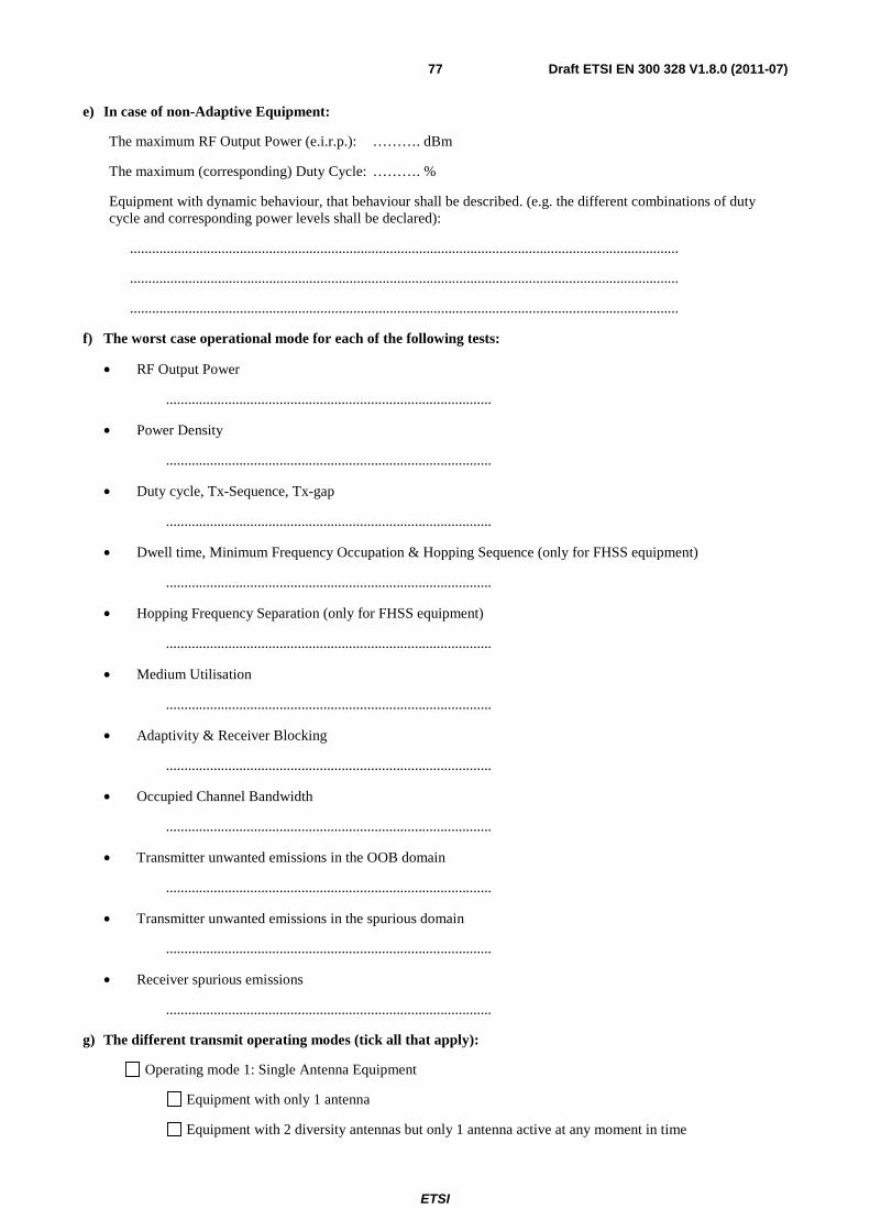
ETSI
Draft ETSI EN 300 328 V1.8.0 (2011-07) 77
e) In case of non-Adaptive Equipment:
The maximum RF Output Power (e.i.r.p.): ………. dBm
The maximum (corresponding) Duty Cycle: ………. %
Equipment with dynamic behaviour, that behaviour shall be described. (e.g. the different combinations of duty cycle and corresponding power levels shall be declared):
......................................................................................................................................................
......................................................................................................................................................
......................................................................................................................................................
f) The worst case operational mode for each of the following tests:
• RF Output Power
.........................................................................................
• Power Density
.........................................................................................
• Duty cycle, Tx-Sequence, Tx-gap
.........................................................................................
• Dwell time, Minimum Frequency Occupation & Hopping Sequence (only for FHSS equipment)
.........................................................................................
• Hopping Frequency Separation (only for FHSS equipment)
.........................................................................................
• Medium Utilisation
.........................................................................................
• Adaptivity & Receiver Blocking
.........................................................................................
• Occupied Channel Bandwidth
.........................................................................................
• Transmitter unwanted emissions in the OOB domain
.........................................................................................
• Transmitter unwanted emissions in the spurious domain
.........................................................................................
• Receiver spurious emissions
.........................................................................................
g) The different transmit operating modes (tick all that apply):
Operating mode 1: Single Antenna Equipment
Equipment with only 1 antenna
Equipment with 2 diversity antennas but only 1 antenna active at any moment in time

ETSI
Draft ETSI EN 300 328 V1.8.0 (2011-07) 78
Smart Antenna Systems with 2 or more antennas, but operating in a (legacy) mode where only 1 antenna is used. (e.g. IEEE 802.11™ [i.3] legacy mode in smart antenna systems)
Operating mode 2: Smart Antenna Systems - Multiple Antennas without beam forming
Single spatial stream / Standard throughput / (e.g. IEEE 802.11™ [i.3] legacy mode)
High Throughput (> 1 spatial stream) using Occupied Channel Bandwidth 1
High Throughput (> 1 spatial stream) using Occupied Channel Bandwidth 2
NOTE: Add more lines if more channel bandwidths are supported.
Operating mode 3: Smart Antenna Systems - Multiple Antennas with beam forming
Single spatial stream / Standard throughput (e.g. IEEE 802.11™ [i.3] legacy mode)
High Throughput (> 1 spatial stream) using Occupied Channel Bandwidth 1
High Throughput (> 1 spatial stream) using Occupied Channel Bandwidth 2
NOTE: Add more lines if more channel bandwidths are supported.
h) In case of Smart Antenna Systems:
• The number of Receive chains: ...........
• The number of Transmit chains: ...........
symmetrical power distribution
asymmetrical power distribution
In case of beam forming, the maximum beam forming gain: ...........
NOTE: Beam forming gain does not include the basic gain of a single antenna.
i) Operating Frequency Range(s) of the equipment:
• Operating Frequency Range 1: ........... MHz to ........... MHz
• Operating Frequency Range 2: ........... MHz to ........... MHz
NOTE: Add more lines if more Frequency Ranges are supported.
j) Occupied Channel Bandwidth(s):
• Occupied Channel Bandwidth 1: ........... MHz
• Occupied Channel Bandwidth 2: ........... MHz
NOTE: Add more lines if more channel bandwidths are supported
k) Type of Equipment (stand-alone, combined, plug-in radio device, ...):
Stand-alone
Combined Equipment (Equipment where the radio part is fully integrated within another type of equipment)
Plug-in radio device (Equipment intended for a variety of host systems)
Other ..................................................................................

ETSI
Draft ETSI EN 300 328 V1.8.0 (2011-07) 79
l) The extreme operating conditions that apply to the equipment:
Operating temperature range: …… °C to ……°C
Operating voltage range: …… V to …… V AC DC
Details provided are for the: stand-alone equipment
combined (or host) equipment
test jig
m) The intended combination(s) of the radio equipment power settings and one or more antenna assemblies and their corresponding e.i.r.p levels:
• Antenna Type:
Integral Antenna
Antenna Gain: ............. dBi
If applicable, additional beamforming gain (excluding basic antenna gain): ............. dB
Temporary RF connector provided
No temporary RF connector provided
Dedicated Antennas (equipment with antenna connector)
Single power level with corresponding antenna(s)
Multiple power settings and corresponding antenna(s)
Number of different Power Levels: .............
Power Level 1: ............. dBm
Power Level 2: ............. dBm
Power Level 3: ............. dBm
NOTE: Add more lines in case the equipment has more power levels.
NOTE: These power levels are conducted power levels (at antenna connector).
• For each of the Power Levels, provide the intended antenna assemblies, their corresponding gains (G) and the resulting e.i.r.p. levels also taking into account the beamforming gain (Y) if applicable
Power Level 1: ............. dBm
Number of antenna assemblies provided for this power level: .........
Assembly # Gain (dBi) e.i.r.p. (dBm)
Part number or model name
1
2
3
4
NOTE: Add more rows in case more antenna assemblies are supported for this power level.
Power Level 2: ............. dBm

ETSI
Draft ETSI EN 300 328 V1.8.0 (2011-07) 80
Number of antenna assemblies provided for this power level: .........
Assembly # Gain (dBi) e.i.r.p. (dBm)
Part number or model name
1
2
3
4
NOTE: Add more rows in case more antenna assemblies are supported for this power level.
Power Level 3: ............. dBm
Number of antenna assemblies provided for this power level: .........
Assembly # Gain (dBi) e.i.r.p. (dBm)
Part number or model name
1
2
3
4
NOTE: Add more rows in case more antenna assemblies are supported for this power level.
n) The nominal voltages of the stand-alone radio equipment or the nominal voltages of the combined (host) equipment or test jig in case of plug-in devices:
Details provided are for the: stand-alone equipment
combined (or host) equipment
test jig
Supply Voltage AC mains State AC voltage ……….. V
DC State DC voltage ……….. V
In case of DC, indicate the type of power source
Internal Power Supply
External Power Supply or AC/DC adapter
Battery
Other: ...................
o) Describe the test modes available which can facilitate testing:
......................................................................................................................................................
......................................................................................................................................................
......................................................................................................................................................

ETSI
Draft ETSI EN 300 328 V1.8.0 (2011-07) 81
p) The equipment type (e.g. Bluetooth®, IEEE 802.11™ [i.3], proprietary, etc.):
......................................................................................................................................................
E.2 Combination for testing (see clause 5.1.3.3 of EN 300 328 V1.8.1)
From all combinations of conducted power settings and intended antenna assembly(ies) specified in sub clause 3.1.m), specify the combination resulting in the highest e.i.r.p. for the radio equipment.
Unless otherwise specified in EN 300 328, this power setting shall be used for testing against the requirements of EN 300 328. In case there is more than one such conducted power setting resulting in the same (highest) e.i.r.p. level, the highest power setting shall be used for testing. See also EN 300 328, clause 5.1.3.3.
Highest overall e.i.r.p. value: ......... dBm
Corresponding Antenna assembly gain: ......... dBi Antenna Assembly #: .........
Corresponding conducted power setting:
(also the power level to be used for testing)
......... dBm Listed as Power Setting #: .........
E.3 Additional information provided by the applicant
E.3.1 Modulation: ITU Class(es) of emission: .................
Can the transmitter operate unmodulated? yes no
E.3.2 Duty Cycle The transmitter is intended for : Continuous duty
Intermittent duty
Continuous operation possible for testing purposes
E.3.3 About the UUT The equipment submitted are representative production models
If not, the equipment submitted are pre-production models ?
If pre-production equipment are submitted, the final production equipment will be identical in all respects with the equipment tested
If not, supply full details
..................................................................................
..................................................................................
The equipment submitted is CE marked

ETSI
Draft ETSI EN 300 328 V1.8.0 (2011-07) 82
In addition to the CE mark, the Class-II identifier (Alert Sign) is affixed.
E.3.4 Additional items and/or supporting equipment provided Spare batteries (e.g. for portable equipment):
Battery charging device
External Power Supply or AC/DC adapter
Test Jig or interface box
RF test fixture (for equipment with integrated antennas)
Host System Manufacturer: ....................
Model #: ....................
Model name: ....................
Combined equipment Manufacturer: ....................
Model #: ....................
Model name: ....................
User Manual
Technical documentation (Handbook and circuit diagrams)

ETSI
Draft ETSI EN 300 328 V1.8.0 (2011-07) 83
Annex F (informative): The EN title in the official languages The enlargement of the European Union (EU) resulted in a requirement from the EU for a larger number of languages for the translation of the titles of Harmonized Standards and mandated ENs that are to be listed in the Official Journal to support the implementation of this legislation.
For this reason the title translation concerning the present document can be consulted via the e-approval application.

ETSI
Draft ETSI EN 300 328 V1.8.0 (2011-07) 84
History
Document history
Edition 1 November 1994 Publication as ETS 300 328
Edition 2 November 1996 Publication as ETS 300 328
Amendment 1 July 1997 Amendment 1 to 2nd Edition of ETS 300 328
V1.2.2 July 2000 Publication as EN 300 328-1
V1.1.1 July 2000 Publication as EN 300 328-2
V1.3.1 December 2001 Publication as EN 300 328-1
V1.2.1 December 2001 Publication as EN 300 328-2
V1.4.1 April 2003 Publication
V1.5.1 August 2004 Publication
V1.6.1 November 2004 Publication
V1.7.1 October 2006 Publication
V1.8.0 July 2011 Public Enquiry PE 20111124: 2011-07-27 to 2011-11-24