harmonics reduction · harmonic propagation. therefore filtering is essential. for the elimination...
TRANSCRIPT
International Research Journal of Engineering and Technology (IRJET) e-ISSN: 2395 -0056
Volume: 02 Issue: 04 | July-2015 www.irjet.net p-ISSN: 2395-0072
© 2015, IRJET ISO 9001:2008 Certified Journal Page 1990
HARMONICS REDUCTION
Reshma E K1
1 PG Scholar, Energy Systems, Nehru College of Engineering and Research Centre, Kerala, India ---------------------------------------------------------------------***---------------------------------------------------------------------
Abstract- Harmonics is a virus which is spread in all
over the power sector areas. It affects the power quality
very badly and also causes energy loss. Harmonics may
damage the equipment due to overheating and
insulation failure etc. Harmonics may cause due to both
manmade and natural reasons. For an industry it
harmonics, so called virus may influence economically
because of the increase of maintenance cost due to
insulation failure or damage of motor winding.
Advanced technologies in electronic equipments also
lead to the generation of harmonics. All the industry
demands distortion free reliable and good quality
electrical energy. This article represents an analysis on
harmonics in an industry and also a mitigation
technique using a passive filter which enables
deterioration free sinusoidal voltage at fairly constant
magnitude throughout the network.
Key Words: Harmonic analyzer, Power quality etc…
1. INTRODUCTION Harmonics are the byproduct of modern electronic equipments which are non linear loads. In today’s environment, all systems use non linear loads. Widespread use of electronics in everything from home electronics to the control of massive and costly industrial process has raised the awareness of power quality. The nonlinear loads produce harmonics in the power network which affect the quality of power supply. The distortion travels back into the power source and can affect other equipments connected to the same source. Hence the reduction in THD will lead to increase the power factor and energy saving despite a slight increase in fundamental source.
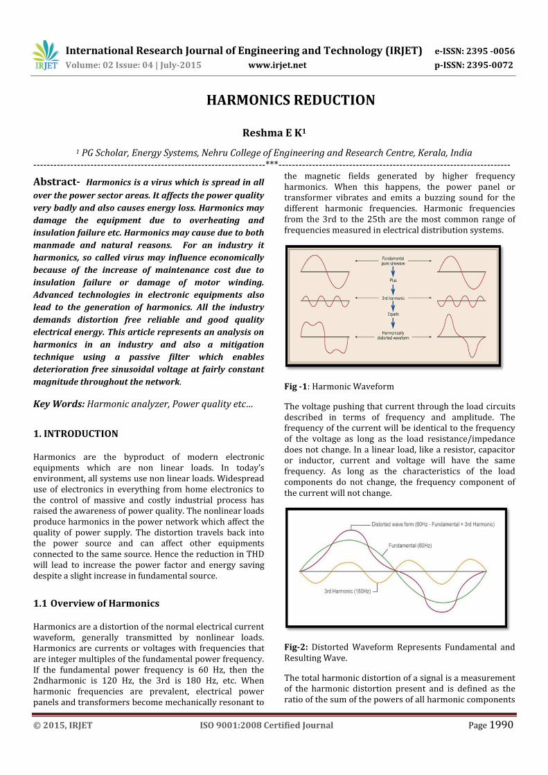
1.1 Overview of Harmonics Harmonics are a distortion of the normal electrical current waveform, generally transmitted by nonlinear loads. Harmonics are currents or voltages with frequencies that are integer multiples of the fundamental power frequency. If the fundamental power frequency is 60 Hz, then the 2ndharmonic is 120 Hz, the 3rd is 180 Hz, etc. When harmonic frequencies are prevalent, electrical power panels and transformers become mechanically resonant to
the magnetic fields generated by higher frequency harmonics. When this happens, the power panel or transformer vibrates and emits a buzzing sound for the different harmonic frequencies. Harmonic frequencies from the 3rd to the 25th are the most common range of frequencies measured in electrical distribution systems.
Fig -1: Harmonic Waveform
The voltage pushing that current through the load circuits described in terms of frequency and amplitude. The frequency of the current will be identical to the frequency of the voltage as long as the load resistance/impedance does not change. In a linear load, like a resistor, capacitor or inductor, current and voltage will have the same frequency. As long as the characteristics of the load components do not change, the frequency component of the current will not change.
Fig-2: Distorted Waveform Represents Fundamental and Resulting Wave.
The total harmonic distortion of a signal is a measurement of the harmonic distortion present and is defined as the ratio of the sum of the powers of all harmonic components

International Research Journal of Engineering and Technology (IRJET) e-ISSN: 2395 -0056
Volume: 02 Issue: 04 | July-2015 www.irjet.net p-ISSN: 2395-0072
© 2015, IRJET ISO 9001:2008 Certified Journal Page 1991
to the power of the fundamental. It provides an indication of the degree to which a voltage or current signal is distorted.
1.2 Phase Sequences of Harmonics Harmonics of different orders have different phase sequences. A phase sequence is the order of rotation of phase vectors relative to each other. Positive phase sequence has a phase order of “abc”, a negative phase sequence has a order of “acb” and a zero phase sequence system, the phase vectors has the same phase angles.
TABLE -1: Phase Sequences
F 2 3 4 5 6 7
Frequency 50
100 150 200 250 300 350
Sequence + - 0 + - 0 +
Zero sequence is called triplen as it is in the multiple of 3 and this is the current following into the neutral of the three phase system.
Also the order of harmonics can be determined by;
n=fn/ff (1)
where,
fn is the frequency of harmonics and ff is the fundamental frequency of the system
2. HARMONIC SOURCES AND ITS EFFECT 2.1 Sources of Harmonics The equipments like motors transformers and other electronic equipments in an industry is a harmonic generator. The non linear loads also create non sinusoidal signals in the circuit leads to the distortion of the signal. These loads absorb frequency current and produce harmonic current in the circuit. The main sources of harmonics are
Transformers Rectifiers and converters Discharge lamps Power capacitors Variable frequency drives Computers and other office equipment UPS Welding controls SCR controlled equipments
2.2 Effect of Harmonics
The following are the effects of harmonics in the electrical power system
Reduce the quality of power The presence of high frequency leads to the
increased copper and iron loss. Then excessive heating is occurred
System efficiency reduces. Electrical interference may lead to misoperation
of communicational devices. Damage of equipments leads to reduce its life Losses in the system increases. Capacitor banks can be exploited due to the
harmonic over voltage.
TABLE -2:
Sources Typical harmonics
6 pulse drive/rectifier 5,7,11,13,17,19,............
12 pulse drive/rectifier 11,13,23,25,..................
18 pulse drive/rectifier 17,19,35,37,..................
Switched mode power supply
3,5,7,9,11,13,................
Fluorescent lights 3,5,7,9,11,13,................
Arcing devices 2,3,4,5,7,......................
Transformer energisation
2,3,4,...........................
3. HARMONICS MITIGATION
Current harmonics is a major issue nowadays. The harmonics are influenced very badly in the increasing demand of electrical energy of industries. So many harmonics mitigation techniques are developed. Impedance of the distribution network damps the harmonic propagation. Therefore filtering is essential. For the elimination process, measuring and identifying the major harmonic content is very important.
3.1. How to Measure Harmonics?
Harmonic analysis is the process of estimating the presence and amount of various harmonic components in a particular section of power system. Harmonic analyzer is the device used to measure the level of harmonic content in a particular circuit. Here we have used a French made power system analyzer manufactured by Monaco info system. The product name of which is KRYKARD ALM 32. The price of the single instrument is well above 4 lakhs. ALM 32 is most users friendly and very easy to handle. Using it we can measure the voltage, current, power, power factor THD levels and the amount of different harmonic levels present. This equipment has 7 input ports. Three for measuring the per phase current and the remaining four for measuring the pre phase voltages with
International Research Journal of Engineering and Technology (IRJET) e-ISSN: 2395 -0056
Volume: 02 Issue: 04 | July-2015 www.irjet.net p-ISSN: 2395-0072
© 2015, IRJET ISO 9001:2008 Certified Journal Page 1992
the neutral voltage. For measuring the values there should not require any direct contact to the high voltage section. It has sensor for this purpose. Each sensor can be clipped to the insulator of the live wire. The sensor senses the parameters without any direct contact to the bare conductor.
3.2. Parameters Measured
V, I, PF, kW, kVA, kVAR, Hz +/-kWh, +/-kVARh, kVAh Harmonics up to 50th on both V and I CF, THD, K-factor, DPF, tangent, phase angles,
Unbalances, Neutral current, Peak V, Peak I Transients (ALM 32) Import &Export of harmonics and Sequence of
harmonics (ALM 32)
3.3. Salient Features
Large Colour LCD screen for graphical menu-driven display
Continuous cycle by cycle measurement of all 3 currents and 3 voltages @ 256 samples/cycle-more accurate and dependable measurements even on non-linear loads with high harmonic content
Suitable for 2 wire, 3 wire and 4 wire measurements
Wide choice for clamp-on CTs to measure currents from 100mA to 3000A – Options include 5/100A CT;1000A,CT;3000A
2 MB memory capacity with programmable interval of data collection from 1 sec to 15 min (4MB memory for ALM 32)
Recorded data can be viewed as trends on the meter screen for quick analysis on the field minimizing dependence on PC/Laptop; Zoom-in/ Zoom-out facility for better resolution enabling in-depth analysis
8 screens (waveforms, vector diagrams, data, etc..) can be stored – can be either viewed on meter or downloaded to PC (12 screen for ALM 32)
Different parameters can be recorded under 4 user-defined configurations; Multiple record sessions can be carried out without deleting data
Captures upto 4096 alarms – min/max value and duration of alarm (minimum ½ cycle detection)
RS-232 serial port for communication and data transfer to a PC. Software part of the kit
Upto 10 hour battery back-up for un-interrupted field studies
The analysis is done at a point called point of common coupling at the main bus bar from where the tapping is taken or where all the equipments are connected. We are measuring the values here in the sense that the effect of harmonics produced by the nonlinear loads is to be kept
reduced here under the permissible levels. Simply we are attaching the three voltage sensors on the insulated bus bar.
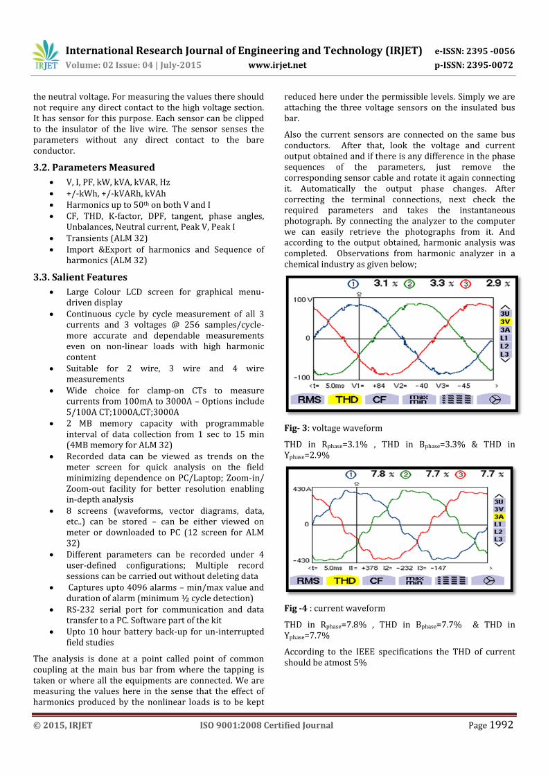
Also the current sensors are connected on the same bus conductors. After that, look the voltage and current output obtained and if there is any difference in the phase sequences of the parameters, just remove the corresponding sensor cable and rotate it again connecting it. Automatically the output phase changes. After correcting the terminal connections, next check the required parameters and takes the instantaneous photograph. By connecting the analyzer to the computer we can easily retrieve the photographs from it. And according to the output obtained, harmonic analysis was completed. Observations from harmonic analyzer in a chemical industry as given below;
Fig- 3: voltage waveform
THD in Rphase=3.1% , THD in Bphase=3.3% & THD in Yphase=2.9%
Fig -4 : current waveform
THD in Rphase=7.8% , THD in Bphase=7.7% & THD in Yphase=7.7%
According to the IEEE specifications the THD of current should be atmost 5%

International Research Journal of Engineering and Technology (IRJET) e-ISSN: 2395 -0056
Volume: 02 Issue: 04 | July-2015 www.irjet.net p-ISSN: 2395-0072
© 2015, IRJET ISO 9001:2008 Certified Journal Page 1993
Fig -5 : THD bar representation
From the above figure it is observed that the presence of 5th harmonics is predominant in the plant. Rphase=9.4%, Bphase=6.4% & Yphase=8.6%. According to IEEE specification, the harmonic limit is 5%
Fig- 6: instantaneous power
Rphase=14.86 W, Bphase=15.68 W & Yphase=15.23 W
Fig -7: Instantaneous power factor
Rphase=0.88, Bphase=0.80 & Yphase=0.89.
From the above analysis the line current THD increase and will not meet the requirements of the harmonic standard limitations. This trade off relation between the power factor and the current THD is another major weakness. Therefore reduced THD comes at the cost of high THD. To overcome this deficiency, a passive filter has been developed.
From the overall summary can be observed that the major harmonics generated in that plant is 5th harmonics. The total harmonic distortion of the voltage due to the flow of these harmonic current is 9.4%. Such high voltage distortion is not desirable and should be brought down to acceptable levels by installation of suitable harmonic filter.
3.4.Design of Filter
A number of aspects must be considered in the design stage of passive filter for controlling problems associated with harmonics. These are summarized as follows;
The capacitive kVAR requirements for power factor correction
Tolerance of filter components may produce undesirable shifts of resonant frequencies and network impedance changes. It will affect the harmonics propagation
Avoid overloading of capacitor banks using a series resistor in single tuned filter
A harmonic filter essentially consists of a power factor capacitor, a tuning reactor and its control gear. It will act parallel with an insulated basic power factor improvement capacitor bank.
For designing purpose we require some data such as load details, existing power factor, required new power factor, total harmonic distribution, individual harmonic details etc. This data can be obtained from a harmonic analyzer. First calculate the total kVAR required to improve the power factor to the desired value. Then distribute the total kVAR into two parts, a normal capacitor bank (untuned) for power factor correction and a filter bank (tuned) for filter purpose. The data obtained from the analyzer, at 80% load,
Load in kW =14.86kW
Power factor= 0.88
5th harmonic current=8.7A
Power factor improvement required=0.98
Assuming required power factor to be 0.98, we calculate the total kVAR required to raise the power factor from 0.88 to0.98
cosϕ1=0.88 & cosϕ2=0.98
kVAR required=kW ( tanϕ1-tanϕ2)
=14.86(0.532-0.2)=5kVAR
Thus we require 5kVAR to raise the power factor to 0.97
But maximum harmonic current distortion as recommended by IEEE specifications C-519-1992 is 4.0
Out of 5 kVAR to be installed we employ 80%kVAR towards filter duty and remaining kVAR for power factor correction.
International Research Journal of Engineering and Technology (IRJET) e-ISSN: 2395 -0056
Volume: 02 Issue: 04 | July-2015 www.irjet.net p-ISSN: 2395-0072
© 2015, IRJET ISO 9001:2008 Certified Journal Page 1994
Thus,
Filter kVAR =80% of 5
=4kVAR
i. Capacitance per phase,C= kVAR/(kV2)*2Π =[(4/3)*103]/[(6.6√3)2 * 2Π* 50 =29.2μF/ph
ii. Capacitive reactance at 50Hz, XC50=1/(2ΠfC) =1/(2Π*50*29.2*10-6 =109.06Ω/ph
iii. Capacitive reactance at 250Hz=1/(2ΠfC) =1/(2Π*250*29.2*10-6) =21.81 Ω/ph
For resonance at 5th harmonic, XC250= XL250=21.81 Ω/ph
iv. Capacitor current at 50Hz, IC50=kVAR/(6.6√3) =4//(6.6√3) =0.34A
v. RMS current, Irms=√[(0.34)2+(9)2] =9A
vi. kVAR rating of the reactor, VL= VL50+ VL250 VL50- Voltage drop across reactor due to the fundamental VL250- voltage drop due to the 5th harmonic
VL= [I50* XL250]+[ I250*XL250] =[1.485]+[196.2] =197.772V
kVAR rating of single reactor= Irms*VL
=197.11*9
=1.78kVAR
vii. kVAR rating of the capacitor, VC= VC50+ VC250
= [(kV*103) √3] + [ I250*XC250] = [3810.5] + [196.2] = 4006.7V
kVAR rating of single capacitor = Irms*VC
=4006.7*9
=36.06kVAR
Based on the observations, it can recommend the installation of 5th harmonic filter, providing a total compensation of 5kVAR. The details of the ratings of the filters are as follows:
6.6kV, 3 phase, 50Hz, 2kVAR reactor
6.6kV, 3 phase, 50Hz, 40kVAR capacitor
Three such capacitors and reactors are used.
4. CONCLUSIONS
Harmonics are a major villain for electrical power systems. By the installation of proper filter we can limit the level of harmonics in an industry. It helps to the reduction of energy loss and good power quality.
ACKNOWLEDGEMENT The authors acknowledge the contributions of the students, faculty of Nehru College of Engineering and Research Centre for helping in the design and fabrication of the dispenser and for tool support. The authors also thank the anonymous reviewers for their thoughtful comments that helped to improve this paper. The authors would like to thank the anonymous reviewers for their constructive critique from which this paper has greatly benefited.
REFERENCES [1] S.Khalid & Bharti Dwivedi, Power Quality Issues,
Problems, Standards & Their Effects In Industry With Corrective Means, International Journal of Advances In Engineering & Technology, Vol.1, Issue 2, May 2011.
[2] Kuldeep Kumar Srivastava, Saquib Shakil and Anand Vardhan Pandey, Harmonics & Its Mitigation Technique by Passive Shunt Filter, International Journal of Soft Computing and Engineering, Vol.3, Issue-2, May 2013,
[3] Robert G. Ellis, A Reference Guide To Causes, Effects And Corrective Measures, An Allen-Bradley Series Of Issues And Answers, April 2001.
[4] Alberto Dolara And Sonia Leva, Power Quality And Harmonic Analysis Of End User Devices, Energies, Vol.5, December 2012.
[5] C. Jettanasen, And C. Pothisarn, Analytical Study Of Harmonics Issued From LED Lamp Driver, IMECS, Vol.II March 2014,
[6] Dr. Kurt Schipman, Dr. François Delincé, The Importance of Good Power Quality, ABB Power Quality Products, Belgium
[7] Haridas M Kakad, Superior solution: IGBT Based Selective Shunt Active Filter (SSAF) for Harmonic Reduction, Electrical India, November 2014