harmonic solutions
TRANSCRIPT

PRICE AND PERFORMANCE CONSIDERATIONS FOR HARMONIC SOLUTIONS
Daniel J. Carnovale, P.E.
[email protected] Eaton | Cutler-Hammer
Moon Township, PA
Thomas J. Dionise, P.E. [email protected]
Eaton | Cutler-Hammer Warrendale, PA
Thomas M. Blooming, P.E. [email protected]
Eaton | Cutler-Hammer Minneapolis, MN
ABSTRACT Problems associated with harmonic distortion are well understood for many power system applications. However, finding the right solution is challenging. There are at least ten different technologies to choose from, each with specific technical and economic advantages. This paper will provide recommendations for reducing harmonic distortion, improving system capacity and improving system reliability while evaluating economic considerations. Special considerations for applying capacitors on a power system with harmonics will be discussed. Issues such as applying a single medium voltage (MV) capacitor or filter versus multiple low voltage (LV) banks will be evaluated. Finally, opportunities for improving energy efficiency using harmonic technologies will be explored. INTRODUCTION This paper assumes that the reader has some basic knowledge of power system harmonics. As a simple refresher – the general acceptable explanation is that harmonic currents flow or are “sourced” from loads and create voltage distortion (or harmonic voltages) as they pass through upstream power system impedance components such as cables, transformers, and generators. In general, the further away from the source of harmonic currents (i.e. the loads), the less voltage distortion you will see. Certainly exceptions exist and harmonic voltages may be “produced” by some equipment (some generators, for example) but the general discussion of this paper deals with standard considerations when dealing with typical harmonic producing loads in commercial and industrial power systems. Often when the subject of power quality arises, people automatically assume that the subject is related to harmonics. These two terms have been interchanged and unfortunately much confusion has occurred as a result. The subject of harmonics is a sub-set of Power Quality (PQ). Other power quality considerations include voltage variations (sags, interruptions, flicker, etc.), transients (surges, lightning, switching events), and grounding – all of which are significant subjects on their own.
Therefore, every PQ problem is not related to harmonics. With regard to harmonic problems, the bottom line is this: Harmonics are not a problem unless they are a problem. As with all power quality concerns, you should not consider something a PQ problem unless the issue is an expense (in terms of utility penalties, monetary losses, production losses or misoperation). Just because you have harmonic currents flowing in your system and you are measuring voltage distortion, you don’t necessarily have a problem. Very often, harmonics issues are raised because the levels have exceeded the IEEE Std 519-1992 recommended limits somewhere in a power system. The fact is most equipment can withstand harmonic distortion levels well above these conservative recommended limits. Harmonics are interesting and can be problematic but often are blamed for problems with no real proof. Take the time to learn about harmonics and how power systems and equipment are actually affected and you’ll save yourself a lot of trouble and certainly a lot of money! Once you have identified that you indeed have a power quality issue related to harmonics, consider this – there are at least ten ways to solve your problem. Which one is right for you and will be the most cost effective solution and which one will clearly relieve the problems that you are experiencing? The economic discussion (choosing which solution is least "best") requires very detailed analysis and this paper will provide guidelines to assist in making that decision. In addition, selecting a harmonic solution is not always an economic decision in every case. Price and performance are definitely interrelated and considerations for both are necessary to clearly select the “best” solution. HARMONIC SOURCES Where do harmonics come from? The general categories of harmonic producing loads (also called non-linear loads) are:
• Power electronic equipment (drives, rectifiers, computers, etc.)

• Arcing devices (welders, arc furnaces, florescent lights, etc.)
• Iron saturating devices (transformers) • Rotating machines (generators)
Today, the most prevalent and growing harmonic sources are:
• Adjustable frequency drives (AFD) • Switch-mode power supplies (computers) • Fluorescent lightning
HARMONIC SYMPTOMS How do you know you have a problem? The only way to know is to identify symptoms of harmonics. Very often, if you recognize specific symptoms of harmonics, the problem has already created issues on your power system. The trick is to recognize “potential” symptoms and identify potential harmonic issues before they occur or to implement correction into the system design. Sometimes modeling and simple calculations will help identify the issues before they become a problem. Symptoms of harmonic problems can be divided into four major areas: Equipment failure and misoperation, economic considerations, application of power factor correction capacitors and other issues. The following symptoms are examples of equipment failure and misoperation associated with harmonics on a power system.
• Voltage notching • Erratic electronic equipment operation • Computer and/or PLC lockups • Overheating (motors, cables, transformers,
neutrals) • Motor vibrations • Audible noise in transformers and rotating
machines • Nuisance circuit breaker operation • Voltage regulator malfunctioning • Generator regulator malfunctioning • Timing or digital clock errors • Electrical fires
The following are economic considerations that should be evaluated with regard to harmonics.
• Losses/inefficiency (motors) • kW losses in cables and transformers • Low total power factor • Generator sizing considerations • UPS sizing consideration • Capacity concerns (transformers, cables)
• Utility imposed penalties Applying power factor correction capacitors requires special considerations with regard to harmonics.
• Capacitor failures • Fuse or breaker (feeding capacitors) nuisance
tripping • Calculated or measured harmonic resonance
conditions (series or parallel resonance) Other significant issues are typically raised with regard to harmonics. Interestingly, these issues are often not real problems but rather hype created by a lack of understanding of harmonics. Many “harmonics problems” are specification issues rather than real problems.
• Metering – do you really have a problem or did you just install a new meter that can show you the waveform and it “looks like” you should have a problem?
• Marketing hype based upon a product spec – do you even have a problem or is somebody scaring you into believing that a problem exists so you buy their product?
• Specmanship – “Thou shall follow IEEE-519…”. While IEEE519 is a recommended practice (note that the key word is “RECOMMENDED”), some thought must be given to the practical side of the standard. In addition, applying the IEEE519 limits at other locations in the power system (other than the point-of-common-coupling, or PCC) is typically overkill and often costly or problematic.
Each one of these symptoms or issues could be discussed in it’s own technical paper but suffice it to say that the magnitude of the “cost” of these symptoms is typically proportional to the complexity and cost of the solution. IEEE STD 519-1992 IEEE Std 519-1992 is “The IEEE Recommended Practice and Requirements for Harmonic Control in Electrical Power Systems”. Many people use the voltage and current distortion limit tables to help determine if harmonics will cause a problem on their power system (or their client’s power system if they are a consultant). This standard has been seriously misused and misquoted over the years. Many times economic solutions are “selected” based on the misapplication of the standard and at a significant cost to the end user.

Sample specifications in excess of the IEEE recommendations
The following is wording from a sample specification. Note: this is not a recommendation but rather a sample of misinterpretation of the IEEE 519 standard for a drive installation.
The harmonic distortion values resulting from the operation of all or any variable frequency drive-driven motor load combinations operating at full load shall be limited as defined in the latest edition of IEEE Standard 519.
This statement is OK but, by the standard, applies only to the PCC (point-of-common-coupling) with the utility – not as defined here. This brings up the broader discussion of the location of the PCC (see following section on PCC). Interestingly, even with this statement as a header (in the same specification), statements 1, 3 and 4 below contradict the IEEE 519 recommendations.
1. Maximum allowable total harmonic voltage distortion (THD): 3% of fundamental
2. Maximum allowable individual frequency harmonic voltage distortion: 3% of fundamental
3. Maximum allowable individual frequency and total harmonic current demand distortion (TDD): 5% of fundamental
4. The harmonic distortion levels shall be specific to the switchboard bus supplying one unit or a group of variable frequency drives
5. The cost of any and all corrective equipment to limit the harmonic levels to these values shall be the responsibility of the manufacturer.
While this specification will significantly minimize any power system harmonics well below any desirable levels, it is clearly beyond the recommendations put forth by the standard. As it turns out, the specifying engineer will cover any potential problems before they occur but will significantly increase the cost of the job. A more practical approach is recommended. That being said, the cost of corrective equipment after the fact is typically higher so the required limitations should be considered and some concessions should be made to both fulfill the IEEE requirements while implementing a practical solution.
Voltage or current harmonics?
Another statement related to IEEE 519 that often causes significant controversy is the following:
The selected firm is to design and implement remedies that would reduce the total harmonic distortion on the secondary side of the main service transformer to less than 5%.
The question in this case is – voltage or current harmonics? The main concern of the standard is voltage distortion. In some cases where the ISC/IL is low (i.e. the loading is a high percentage of the system capacity), the current distortion limit is 5% (but merely to minimize the voltage distortion). The IEEE 519 Standard clearly states that harmonic currents should be reduced to minimize voltage distortion. Harmonic currents should also be reduced to minimize loading on the system but even the maximum allowable (20%) distortion will only increase the total root-mean-square (rms) current by approximately 2%.
PCC
By the Standard, the PCC is where other utility customers can be served and is not necessarily the secondary of the main service transformer and is certainly not a downstream panelboard, MCC, feeder or load. Note that sometimes in utility contracts, the PCC can be explicitly defined at locations other than as defined in IEEE 519, such as a metering point. Also, be wary of equipment manufacturer, contractors or engineers insisting that a single load must comply with the IEEE-519 voltage and current recommendations. This was never the intention of the standard. HARMONIC SOLUTIONS The following are harmonic solutions that are commercially available products or combinations of products for reducing harmonic currents and minimizing harmonic voltage distortion on a power system. The harmonic solutions are divided into three major categories: drive and rectifier solutions (typical for industrial facilities), solutions for commercial facilities and harmonic solutions to correct power factor.
Drives and Rectifier Solutions The following solutions are for drive or three-phase rectifier (large UPSs, for example) applications where a significant amount of harmonic current is generated.

Line Reactors
A Line Reactor (choke) is a 3-phase series inductance on the line side of a drive. If a line reactor is applied on all AFDs, it is possible to meet IEEE guidelines where up to 15% to 40% of system loads are AFDs, depending on the stiffness of the line and the value of line reactance. Line reactors are available in various values of percent impedance, most typically 1-1.5%, 3%, and 5%.
Figure 1 – Line Reactor
IEEE 519A shows an example of the benefit of using line reactors in Figure 2. Table 1 is a summary of the typical current distortion for a drive with a line reactor of varying sizes.
Figure 2 - IEEE 519A – Benefit of Line Reactors
Line Reactor Expected Individual Drive
Harmonic Current Distortion 1% 80% 3% 35-45% 5% 30-35%
Table 1 – Line Reactor vs. Expected Harmonics
Advantages • Low cost • Can provide moderate reduction in voltage and
current harmonics • Available in various values of percent
impedance • Provides increased input protection for AFD
and its semiconductors from line transients
Disadvantages • May require separate mounting or larger AFD
enclosure • May not reduce harmonic levels to below
IEEE519 1992 guidelines
K-Factor and Drive Isolation Transformers
Underwriters Laboratories (UL) and transformer manufacturers established a rating method, the K-Factor, for dry-type transformers to evaluate their suitability for duty in a harmonic environment. The K-factor relates the transformer capability to supply varying degrees of nonlinear load without exceeding the rated temperature rise limits of the transformer. The K-factor is based upon predicted losses as specified in the simplified method of IEEE Std C57.110-1986, IEEE Recommended Practice for Establishing Transformer Capability When Supplying Non-sinusoidal Load Currents (ANSI). The limiting factor related to overheating is again assumed to be eddy current losses in the windings. K-factor rated transformers offer no means to reduce the magnitudes of harmonic current (except that they offer line reactance – see Line Reactors). But the K-factor method allows the engineer to choose a dry type transformer that can withstand the harmonic duty without damage or loss of performance. Standard K-factor ratings are 4, 9, 13, 20, 30, 40, and 50. Drive Isolation Transformers are similar to K-factor transformers in that they offer line impedance similar to a Line Reactor and reduce the amount of harmonic current that is “allowed” to flow to the load but otherwise do not reduce the harmonics from the drive. Generally, they are a 1:1 ratio transformer and are used to protect other loads from the high frequencies created by the drive and are used in combinations to create a 12-Pulse Distribution System.
M
Figure 3 – Drive Isolation Transformer
Advantages
• Can provide moderate reduction in voltage and current harmonics by adding source reactance
• Can purchase various values of percent impedance according to needs
• Provides increased input protection for AFD and its semiconductors from line transients
• Can be used in combinations with line reactors and transformers for harmonic cancellation.
Disadvantages • K-factor transformers by themselves are a
method for “living with” harmonics but will not significantly reduce the harmonics over the less expensive reactor solution.
• Must be sized (fully rated) to match each drive or group of drives.
• Cannot typically take advantage of diversity of loads.
• May not reduce harmonic levels to below IEEE519 1992 guidelines
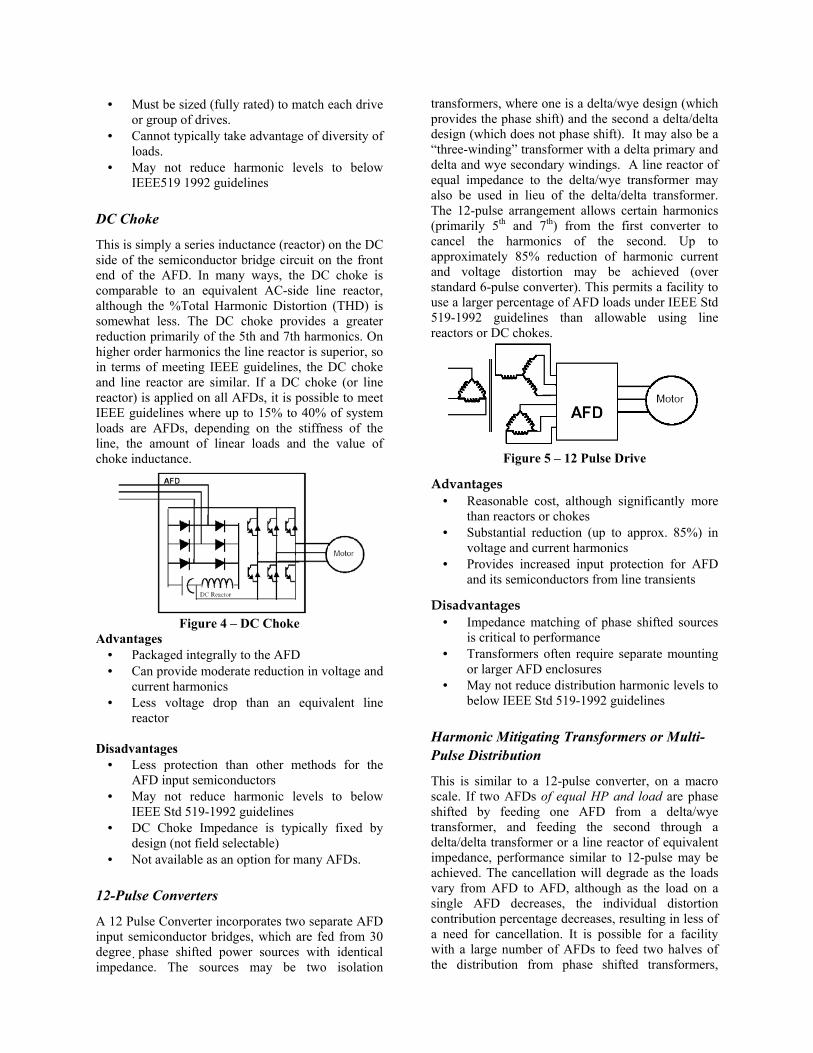
DC Choke
This is simply a series inductance (reactor) on the DC side of the semiconductor bridge circuit on the front end of the AFD. In many ways, the DC choke is comparable to an equivalent AC-side line reactor, although the %Total Harmonic Distortion (THD) is somewhat less. The DC choke provides a greater reduction primarily of the 5th and 7th harmonics. On higher order harmonics the line reactor is superior, so in terms of meeting IEEE guidelines, the DC choke and line reactor are similar. If a DC choke (or line reactor) is applied on all AFDs, it is possible to meet IEEE guidelines where up to 15% to 40% of system loads are AFDs, depending on the stiffness of the line, the amount of linear loads and the value of choke inductance.
Figure 4 – DC Choke
Advantages • Packaged integrally to the AFD • Can provide moderate reduction in voltage and
current harmonics • Less voltage drop than an equivalent line
reactor Disadvantages
• Less protection than other methods for the AFD input semiconductors
• May not reduce harmonic levels to below IEEE Std 519-1992 guidelines
• DC Choke Impedance is typically fixed by design (not field selectable)
• Not available as an option for many AFDs.
12-Pulse Converters
A 12 Pulse Converter incorporates two separate AFD input semiconductor bridges, which are fed from 30 degree phase shifted power sources with identical impedance. The sources may be two isolation
transformers, where one is a delta/wye design (which provides the phase shift) and the second a delta/delta design (which does not phase shift). It may also be a “three-winding” transformer with a delta primary and delta and wye secondary windings. A line reactor of equal impedance to the delta/wye transformer may also be used in lieu of the delta/delta transformer. The 12-pulse arrangement allows certain harmonics (primarily 5th and 7th) from the first converter to cancel the harmonics of the second. Up to approximately 85% reduction of harmonic current and voltage distortion may be achieved (over standard 6-pulse converter). This permits a facility to use a larger percentage of AFD loads under IEEE Std 519-1992 guidelines than allowable using line reactors or DC chokes.
Figure 5 – 12 Pulse Drive
Advantages • Reasonable cost, although significantly more
than reactors or chokes • Substantial reduction (up to approx. 85%) in
voltage and current harmonics • Provides increased input protection for AFD
and its semiconductors from line transients
Disadvantages • Impedance matching of phase shifted sources
is critical to performance • Transformers often require separate mounting
or larger AFD enclosures • May not reduce distribution harmonic levels to
below IEEE Std 519-1992 guidelines
Harmonic Mitigating Transformers or Multi-Pulse Distribution
This is similar to a 12-pulse converter, on a macro scale. If two AFDs of equal HP and load are phase shifted by feeding one AFD from a delta/wye transformer, and feeding the second through a delta/delta transformer or a line reactor of equivalent impedance, performance similar to 12-pulse may be achieved. The cancellation will degrade as the loads vary from AFD to AFD, although as the load on a single AFD decreases, the individual distortion contribution percentage decreases, resulting in less of a need for cancellation. It is possible for a facility with a large number of AFDs to feed two halves of the distribution from phase shifted transformers,

yielding a large reduction in harmonic levels for minimal cost, and allowing a higher percentage of AFD loads under IEEE Std 519-1992 guidelines. Multiple transformers can be used to develop different phase shifts between sources of harmonic currents. For example, two transformers with a 60 Hz phase shift of 30 degrees between them will result in cancellation of the 5th , 7th , 17th , and 19th, etc. harmonics and will resemble 12 pulse drive system. Four transformers shifted by 15 degrees with respect to each other will result in a 24-pulse distribution and will significantly minimize the resulting harmonics upstream of the common bus.
Figure 6 – 12 Pulse Distribution
Advantages • Cost may either be low or high depending on
implementation • Provides substantial reduction (50-80%) in
voltage and current harmonics • Provides increased input protection for AFD
and its semiconductors from line transients
Disadvantages • Cost may be low or high depending on
implementation • Impedance matching of phase shifted sources
is critical to performance • Maximum cancellation occurs only if drive
loading is balanced • Transformers will require separate mounting • May not reduce harmonic levels to below
IEEE Std 519-1992 guidelines
Tuned Harmonic Filters
Tuned harmonic filters consist of the combination of a reactor and capacitor elements. Power factor correction can be incorporated into a filter design but care must be taken if a filter is applied on a system level so that the 60 Hz capacitive compensation does
not increase the system voltage significantly during lightly loaded conditions. Often, a switched harmonic filter (in steps of 50 kvar, for example) can be used to regulate the amount of 60 Hz and filtering required by dynamically changing loads. These filters are installed in a shunt arrangement on the line side of the AFD or on a common bus for multiple drive loads. The tuned filter is a short circuit or very low impedance at the “tuned” frequency. For drive loads, tuned filters are tuned somewhat below the 5th harmonic, which is the largest component of harmonic distortion. The filter will also absorb some 7th harmonic current. A 7th harmonic filter or additional filters tuned to higher order harmonics may also be used. More care is needed with the application of tuned harmonic filters than with other methods. The filter can be overloaded if care is not taken to account for all of the harmonic sources on a system. If additional AFD or non-linear loads are added without filtering, the previously installed filters may become overloaded (they are generally fused for protection). For industrial applications, an optional line reactor used in conjunction with the filter minimizes the possibility of this occurring and enhances the filter performance (total reactance is often split between the AFD/internal reactor and optional reactor).
Figure 7 – Tuned Filter
Many times, if power factor correction is required on a power system with harmonic sources, a tuned harmonic filter will be applied in lieu of capacitors to supply the reactive power requirements while providing a predictable resonant frequency.
Advantages • Allow a higher percentage of AFD system
loads than line reactors and chokes • Provides power factor correction • A single filter can compensate for multiple
drives
Disadvantages • Higher cost
TunedFilter
Optional Reactor
May be replaced with a
line reactor

• Separate mounting and protective device (breaker/fuse) required
• May not reduce harmonic levels to below IEEE Std 519-1992 guidelines
• Care is needed in application to ensure that the filter will not become overloaded
• Care is needed in application to ensure that overcompensation will not raise the voltage significantly
• Could result in leading power factors at during lightly loaded conditions
Broadband Blocking Filters
These filters are similar to Tuned Filters but have some major design differences. As Tuned Filters are connected in parallel to the harmonic loads, Broadband Filters are connected in series with the AFD and carry the full AFD current. This difference provides added protection for the input power section of the AFD. Broadband Filters require no tuning, improve power factor for the system and minimize all harmonic frequencies, including the 3rd harmonic. Additionally, they avoid system resonance and are not overloaded by harmonics from other loads.
Figure 8 – Broadband Drive Filter Advantages
• Allows a higher percentage of AFD system loads than line reactors and chokes
• Provides increased input protection for AFD and its semiconductors from line transients
• Provides added protection for AFD input power section
• Provides system power factor correction • Typical blocking filters simulate 12/18 pulse
drive harmonics Disadvantages
• High cost • Separate mounting required • Requires one filter per drive • May not reduce harmonic levels to below
IEEE Std 519-1992 guidelines • Could result in leading power factors during
lightly loaded conditions
18 Pulse Converter – Differential Delta
This method is similar to 12-pulse converters, although instead of using two phase shifted power sources and semiconductor bridges, three are used. One manufacturer uses a specially wound autotransformer (Differential Delta) and 18 input semiconductors. When this arrangement is used, over 90% of harmonic currents are canceled (Typical total harmonic current distortion of 2-3%).
Figure 9 – Differential Delta (18 Pulse) Drive
Advantages
• Virtually guarantees compliance with IEEE Std 519-1992 – excellent for drives >100 HP
• Provides increased input protection for AFD and its semiconductors from line transients
• Up to 4 times the harmonic reduction of 12 pulse methods
• Smaller transformer than isolation transformer used in 12-pulse converter
Disadvantages • Higher cost (but much better performance) • Larger and heavier magnetics than some other
methods
Active Filters
This method uses sophisticated electronics and power section IGBTs to inject equal and opposite harmonics onto the power system to cancel those generated by other loads. These filters monitor the non-linear currents demanded from non-linear loads (such as AFDs) and electronically generate currents that match and cancel the load harmonic currents. Active Filters are inherently non-resonating and are easily connected in parallel with system loads. Active harmonic filters can be used to compensate for harmonics, harmonics and power factor or simply for power factor. They can also be used with existing power factor correction capacitors without concern for harmonic resonance.

Parallel (the more common type) active harmonic filters compensate for harmonic load currents. Parallel (shunt) active filters compensate for voltage distortion caused by the load by canceling harmonic load currents. Series active harmonic filters compensate for source harmonics (voltage) but do not compensate for harmonic load currents. Series filters are generally used to protect the load from damaging source harmonics whereas the shunt filters are designed to protect the system from the load harmonics. The shunt active filter will compensate for harmonics and power factor up to its maximum capability and it cannot be overloaded.
Figure 10 (a) – Series Active Filter
Figure 10 (b) – Series Active Filter
Advantages • Guarantees compliance with IEEE Std 519-
1992 if sized correctly • Shunt unit cannot be overloaded even as future
harmonic loads are added • Harmonic cancellation from the 2nd to 50th
harmonic • Shunt connected unit provides easy installation
with no major system rework • Provides reactive (var) currents improving
system power factor • Can be designed into an MCC to compensate
for several AFDs Disadvantages
• Typically more expensive than other methods due to the high performance control and power sections
• Series unit must be sized for total load
Solutions for Commercial Facilities On a 3-phase, 4-wire power system supplying power to single-phase switch-mode power supplies (computer power supplies, for example) or florescent lighting, significant harmonics (all odd harmonics, generally) flow on the phase conductors as a result of the non-linear current drawn by the loads. On the neutral conductor, the 3rd harmonic currents (and all odd multiples of the 3rd harmonic, 9th, 15th, etc. – also
called triplens) from each phase are added together and can overload the neutral conductors, connections in panelboards and transformers if the situation is not addressed. The neutral current can approach 175% of the phase conductor current. There are a variety of ways to eliminate the harmonics or “live with” the resulting harmonics. Each solution has economic and technical advantages and disadvantages. The following are typical and commercially available solutions for problems associated with 3rd harmonics on power systems.
Neutral Blocking Filter
A neutral blocking filter is a capacitor and reactor combination that that is connected in series with the neutral conductor. These components are “parallel resonant” at the 3rd harmonic allowing 60 Hz (normal load) current to flow but are an extremely high impedance for the 3rd harmonic current and do not allow the load to “source” current at that frequency. Applying this type of filter to a distribution transformer blocks all downstream loads from generating 3rd harmonics. This has the added benefit of reducing the load current (rms) from all loads and can significantly reduce the losses in the transformer and conductors between the transformer and the loads.
Load Load Load
NeutralBlocking
Filter
Load Load Load
NeutralBlocking
Filter
Figure 11 – Neutral Blocking Filter
Advantages • Reduces neutral currents by more than 80%
(by preventing 3rd harmonic current flow) • Decreases rms phase current by 10-30% • Releases un-useable capacity by as much as
30% • Removes 3rd harmonic current from all the
system neutrals, from the transformer out to the furthest outlet
• Best potential for energy savings

Disadvantages • High cost • Sized for transformer neutral maximum
expected load • May increase voltage distortion at load
terminals.
Zig-zag Transformers (Zero-Sequence Traps)
The third harmonics generated by single-phase non-linear loads flow back throughout the shared neutral. If the transformer is not designed to “handle” the excessive harmonic currents or if the upstream neutral circuit is not oversized, the harmonics must be addressed prior to the transformer. A zig-zag transformer either externally applied (also called a “zero-sequence trap”) to an existing delta-wye transformer or built into the transformer itself (the winding configuration would then be delta zig-zag, typically), provides very low impedance for 3rd harmonic (and odd multiples of the 3rd) currents. The application of a zig-zag transformer or a delta/zig-zag distribution transformer simply provides an alternate path for the 3rd harmonic currents to flow and do not allow the current to flow back through the main step down transformer. This reduces the overall voltage distortion upstream of the transformer and/or for other parallel loads, in some cases, downstream. An optional line reactor is sometimes applied to reduce the current division between the original transformer and the new zig-zag transformer and to force most of the 3rd harmonic current through the zig-zag.
Load Load Load
Zig-zagTransformer
Optional Neutral Reactor
Load Load Load
Zig-zagTransformer
Optional Neutral Reactor
Figure 12 – Zig-zag Transformer
Advantages • May be retrofitted to existing systems or may
be specified on new construction where significant single-phase harmonic currents are expected.
• May or may not increase system cost significantly depending upon the application and design.
Disadvantages • May or may not increase system cost
significantly depending upon the application and design.
• Allows harmonics to flow but simply provides a low impedance path back to source.
• May increase available fault current by reducing the zero sequence impedance.
• May increase harmonics by reducing the source impedance from the load standpoint.
Oversized Neutral, K-rated Transformers and/or Transformer De-rating
Understanding that magnitude of the current in the neutral circuit can approach 175% of the current in the phases when significant 3rd order harmonics are present, several methods have been developed to “live with” the increased current without spending a significant amount of money. These methods involve either increasing the harmonic capacity of the power system components or de-rating the components to accommodate the harmonic currents. One method of de-rating the power system components is to double the size of the neutral conductor. This involves increasing the neutral conductor size to twice the size of the phase conductor in any circuits where a “shared neutral” is used. This includes panelboards and shared neutral circuits such as are found in cubicle subcircuits in office buildings, for example. Today, for many installations every circuit includes a phase conductor and its own neutral conductor. Therefore, the only truly “shared” neutral is in the panelboard and on the transformer. However, for existing facilities, this is definitely not the case. K-rated transformers are designed to “live with” excessive harmonic currents while maintaining typical values of impedance as described earlier in this paper (i.e., these are not simply oversized transformers). Typically, the windings and neutral have a significantly higher rating compared to a standard transformer and the standard connection is delta/wye. The delta winding is said to “trap” the triplen harmonics (3rd’s and multiples of the 3rd) but both sets of windings must be rated to accommodate the harmonic currents. For systems supplying primarily switch-mode power supply loads, a K13 or K20 may be required in order to utilize the entire rated capacity (kVA).
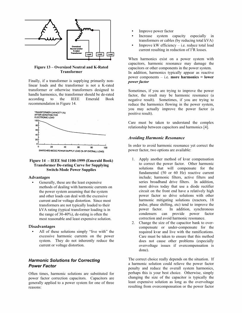
Figure 13 – Oversized Neutral and K-Rated Transformer
Finally, if a transformer is supplying primarily non-linear loads and the transformer is not a K-rated transformer or otherwise transformers designed to handle harmonics, the transformer should be de-rated according to the IEEE Emerald Book recommendation in Figure 14.
Figure 14 – IEEE Std 1100-1999 (Emerald Book)
Transformer De-rating Curve for Supplying Switch-Mode Power Supplies
Advantages • Generally, these are the least expensive
methods of dealing with harmonic currents on the power system assuming that the system and other loads can deal with the excessive current and/or voltage distortion. Since most transformers are not typically loaded to their kVA rating (typical transformer loading is in the range of 30-40%), de-rating is often the most reasonable and least expensive solution.
Disadvantages • All of these solutions simply “live with” the
excessive harmonic currents on the power system. They do not inherently reduce the current or voltage distortion.
Harmonic Solutions for Correcting Power Factor Often times, harmonic solutions are substituted for power factor correction capacitors. Capacitors are generally applied to a power system for one of three reasons:
• Improve power factor • Increase system capacity especially in
transformers or cables (by reducing total kVA) • Improve kW efficiency – i.e. reduce total load
current resulting in reduction of I2R losses. When harmonics exist on a power system with capacitors, harmonic resonance may damage the capacitors or other components in the power system. In addition, harmonics typically appear as reactive power components – i.e. more harmonics = lower power factor Sometimes, if you are trying to improve the power factor, the result may be harmonic resonance (a negative result). Sometimes, if you are trying to reduce the harmonics flowing in the power system, you may actually improve the power factor (a positive result). Care must be taken to understand the complex relationship between capacitors and harmonics [4].
Avoiding Harmonic Resonance
In order to avoid harmonic resonance yet correct the power factor, two options are available:
1. Apply another method of kvar compensation to correct the power factor. Other harmonic solutions that will compensate for the fundamental (50 or 60 Hz) reactive current include; harmonic filters, active filters and series broadband drive filters. In addition, most drives today that use a diode rectifier circuit on the front end have a relatively high power factor so drive solutions with other harmonic mitigating solutions (reactors, 18 pulse, phase shifting, etc) tend to improve the power factor. In addition, synchronous condensers can provide power factor correction and avoid harmonic resonance.
2. Change the size of the capacitor bank to over-compensate or under-compensate for the required kvar and live with the ramifications. Care must be taken to ensure that this method does not cause other problems (especially overvoltage issues if overcompensation is done).
The correct choice really depends on the situation. If a harmonic solution could relieve the power factor penalty and reduce the overall system harmonics, perhaps this is your best choice. Otherwise, simply changing the size of the capacitor is typically the least expensive solution as long as the overvoltage resulting from overcompensation or the power factor
Load Load Load
Oversized Neutral and/or
K-rated Transformer Load Load Load
Oversized Neutral and/or
K-rated Transformer
penalty resulting from under compensation are acceptable.
Low Voltage versus Medium Voltage Solutions
One important factor for applying capacitors or harmonic solutions for correcting power factor is whether the solution should be applied at the low voltage (LV) or medium voltage (MV) level. If the power factor penalty is the only concern, a medium voltage solution is typically the most economical choice for larger banks (typically > 1500 kVA). In addition, harmonic resonance is often easier to avoid at the MV level meaning that straight capacitors can be applied. However, for multistage banks, MV switching adds significant cost and therefore, the banks at MV typically have larger switched or fixed stages. If improving system capacity or improving kW efficiency are significant concerns, then applying LV solutions is always the most economic choice. In addition, for smaller kvar requirements, LV banks are almost always the most economic solution.
HOW CAN REDUCING HARMONICS SAVE YOU MONEY? Correcting a harmonic problem can save money in obvious ways if the problem resulted in physical damage to equipment or misoperation of equipment. Alleviating these issues show an immediate payback if the damage or the cost associated with the misoperation are more substantial than the cost of the solution. Other subtle but sometimes significant issues arise as a result of harmonic currents flowing throughout the power system distorting the voltage. These issues primarily relate to the costs associated with the reduced efficiency of power system equipment operating at frequencies other than the 50 or 60 Hz for which they were designed. The following are some ways that harmonics can cost you money without you realizing it. 1. Transformers, motors, generators, cables and
UPS systems are often over designed when harmonics are present and the cost associated with this over design is or can be significant. Consider the following example.
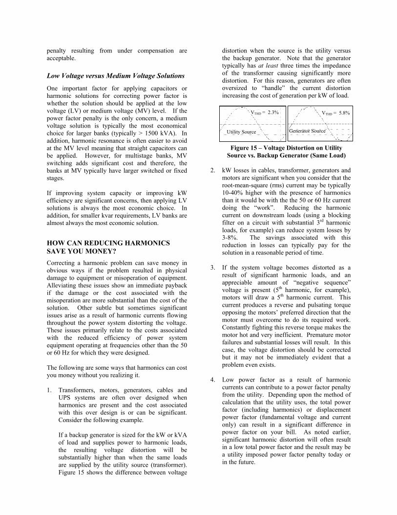
If a backup generator is sized for the kW or kVA of load and supplies power to harmonic loads, the resulting voltage distortion will be substantially higher than when the same loads are supplied by the utility source (transformer). Figure 15 shows the difference between voltage
distortion when the source is the utility versus the backup generator. Note that the generator typically has at least three times the impedance of the transformer causing significantly more distortion. For this reason, generators are often oversized to “handle” the current distortion increasing the cost of generation per kW of load.
Figure 15 – Voltage Distortion on Utility
Source vs. Backup Generator (Same Load) 2. kW losses in cables, transformer, generators and
motors are significant when you consider that the root-mean-square (rms) current may be typically 10-40% higher with the presence of harmonics than it would be with the the 50 or 60 Hz current doing the “work”. Reducing the harmonic current on downstream loads (using a blocking filter on a circuit with substantial 3rd harmonic loads, for example) can reduce system losses by 3-8%. The savings associated with this reduction in losses can typically pay for the solution in a reasonable period of time.
3. If the system voltage becomes distorted as a
result of significant harmonic loads, and an appreciable amount of “negative sequence” voltage is present (5th harmonic, for example), motors will draw a 5th harmonic current. This current produces a reverse and pulsating torque opposing the motors’ preferred direction that the motor must overcome to do its required work. Constantly fighting this reverse torque makes the motor hot and very inefficient. Premature motor failures and substantial losses will result. In this case, the voltage distortion should be corrected but it may not be immediately evident that a problem even exists.
4. Low power factor as a result of harmonic
currents can contribute to a power factor penalty from the utility. Depending upon the method of calculation that the utility uses, the total power factor (including harmonics) or displacement power factor (fundamental voltage and current only) can result in a significant difference in power factor on your bill. As noted earlier, significant harmonic distortion will often result in a low total power factor and the result may be a utility imposed power factor penalty today or in the future.
VTHD = 2.3% VTHD = 5.8%
Utility Source Generator Source
SINGLE LOAD VERSUS SYSTEMS APPROACH FOR HARMONIC SOLUTIONS The decision to apply one harmonic solution over another is typically an economic one but is also highly dependent upon the effectiveness of the solution. Table 2 shows the “general” effectiveness of various harmonic solutions. For each solution the resulting typical ITHD is shown. For example, a line reactor is certainly much less expensive than an active filter but a typical line reactor will only reduce the current harmonics to approximately 35% while an active filter will reduce the current distortion to less than 5% ensuring that harmonic problems will most likely be eliminated. Figure 16(a) and 16(b) demonstrate the cost of various harmonic solutions for a single load versus a systems approach. Figure 16(c) shows that when the cost of a drive is added to the cost of various solutions, the cost of the solutions are much more comparable and the effectiveness of each solution becomes the key decision criteria.
SUMMARY Tables 2 and 3 summarize the harmonic solutions discussed in this paper. Table 2 defines the solutions with reference to harmonic correction equipment type and Table 3 describes the solutions with reference to load types. The tables indicate the most significant advantages and disadvantages of each technology. Details of other advantages and disadvantages for each solution are shown in the main body of this paper. The decision for applying harmonic solutions at LV or MV and whether that solution should be applied to an individual load or as a “system” solution, is dependent on the economics of the situation as well as the effectiveness of the solution(s).
Each solution has merit given different circumstances. Selecting the right solution requires experience with each type of technology to insure that it is the best technical and economic solution for the application. REFERENCES 1. D. J. Carnovale, “Applying Harmonic Solutions
to Commercial and Industrial Power Systems.” Globalcon, 2003, Boston, MA.
2. IEEE Standard 1100-1999 – IEEE
Recommended Practice for Powering and Grounding Electronic Equipment (Emerald Book)
3. IEEE Standard 519-1992 – IEEE Recommended
Practices and Requirements for Harmonic Control in Electrical Power Systems
4. D. J. Carnovale, “Power Factor Correction and
Harmonic Resonance: A Volatile Mix,” EC&M Magazine, June, 2003.
5. T. Key and J. Lai, “Cost and Benefit of
Harmonic Current Reduction for Switch-Mode Power Supplies in a Commercial Office Building,” in IEEE Transactions on Industry Applications, Vol. 32, No 5, September/October 1996.
6. J. K. Piel and D. J. Carnovale, “Economic and
Electrical Benefits of Harmonic Reduction Methods in Commercial Facilities.” EPRI PQA 2003, Monterey, CA
7. IEEE P519A – Draft 7. Harmonics Working
Group – “Recommended Practices and Guide for Applying Harmonic Limits on Power Systems”, Copyright 2000.

Table 2 – Comparison of Harmonic Solution Options by Corrective Equipment
Solution Type (and typical effectiveness)
Significant Advantages Significant Disadvantages
Shunt/Parallel Filter Solutions Passive Harmonic Filter (typical remaining ITHD < 15%)
• Typically reduces most prevalent harmonics (typically 5th) to acceptable level
• Provides PF correction support • Avoids resonance by selecting “tuned” frequency
• Typically requires system knowledge and application study/analysis
Active Harmonic Filter (typical remaining ITHD < 5%)
• Excellent cancellation for 2nd through 50th harmonic currents
• Cannot be overloaded • Can take advantage of diversity of loads
• Typically, highest cost
Series Filters/Reactors Active Harmonic Filter (typical remaining ITHD < 5%)
• Excellent power conditioning for removing source voltage harmonics
• Typically, highest cost • Does not reduce current harmonics
Neutral Blocking Filter (typical 3rd harmonic is reduced to < 10%)
• Only solution that eliminates the 3rd harmonic current from load
• Relieves system capacity and has potential for energy savings
• High cost • May increase voltage distortion at loads
Broadband Blocking Filters – Drives (typical remaining ITHD < 8% or 12% - depending on type)
• Makes 6-pulse into 18-pulse equivalent at reasonable cost • Higher cost • Requires one filter per drive
AC Line Reactors (typical remaining ITHD < 35%)
• Inexpensive • For 6-pulse standard drive/rectifier, can reduce harmonic
current distortion from 80% down to about 35-40%
• May require additional compensation
DC Reactors for Drives (typical remaining ITHD < 35%)
• Slightly better than ac line reactors for 5th and 7th harmonics
• Not always an option for drives • Less protection for input semiconductors
Transformer Solutions Isolation Transformers (typical remaining ITHD < 35%)
• Offers series reactance (like line reactors) and provides electrical isolation for some transient protection
• No advantage over reactors for reducing harmonics unless used in pairs for phase shifting
Transformer De-rating • Typically, most reasonable (cost) solution • Does not remove harmonics Harmonic Mitigating Transformers (typical remaining ITHD < 15% is possible)
• Substantial (50-80%) reduction in harmonics when used in tandem
• Harmonic cancellation highly dependent on load balance
• Must have even multiples of matched loads
Neutral Cancellation Transformer – Zero Sequence Trap (typical 3rd harmonic is reduced to < 10%)
• “Handles” 3rd harmonics re-circulating them back to the load
• Can reduce other (5th and 7th) harmonics when used as phase-shifting pairs
• Reduces voltage “flat-topping”
• Requires fully rated circuits (and oversized neutrals) downstream to loads
18 Pulse Drive Systems (or higher) (typical ITHD < 5%)
• Excellent harmonic control for larger drives (>100HP) • Insures Std IEEE 519-1992 compliance
• Higher cost
K-Factor Transformers • Offers series reactance (like line reactors) and provides electrical isolation for some transient protection
• No advantage over reactors for reducing harmonics unless used in pairs for phase shifting
Other Oversized Neutrals • “Live-with” high 3rd harmonics • All downstream panels and shared neutrals
must be oversized. • Transformer windings and neutral must be
sized for high harmonics

Table 3 – Comparison of Harmonic Solution Options by Load Type
Load Type Optional Solutions Significant Advantages Significant Disadvantages Drives/Rectifiers (includes large 3-phase UPS loads)
Line Reactors • Inexpensive • For 6-pulse standard drive/rectifier, can reduce
harmonic current distortion from 80% down to about 35-40%
• May require additional compensation
K-Rated/Drive Isolation Transformer
• Offers series reactance (like line reactors) and provides electrical isolation for some transient protection
• No advantage over reactors for reducing harmonics unless used in pairs for phase shifting
DC Choke • Slightly better than ac line reactors for 5th and 7th harmonics
• Not always an option for drives • Less protection for input
semiconductors 12-Pulse Converter • 85% reduction versus standard 6-pulse • Often not substantially less cost than
18-pulse or blocking filter Harmonic Mitigating
Transformers/Phase Shifting
• Substantial (50-80%) reduction in harmonics when used in tandem
• Harmonic cancellation highly dependent on load balance
• Must have even multiples of matched loads
Tuned Filters • Bus connected – accommodates load diversity • Provides PF correction
• Requires application analysis
Broadband Filters • Makes 6-pulse into 18-pulse equivalent at reasonable cost
• Higher cost • Requires one filter per drive
18-Pulse Converter • Excellent harmonic control for larger drives (>100HP)
• Insures Std IEEE 519-1992 compliance
• Higher cost
Active Filters • Best and most complete solution up to 50th harmonic
• Can take advantage of load diversity
• Typically highest cost
Computers/Switch-Mode Power Supplies
Neutral Blocking Filter • Only solution that eliminates the 3rd harmonic current from load
• Relieves system capacity and has potential for energy savings
• High cost • May increase voltage distortion
Zig-Zag/Harmonic Mitigating Transformers
• “Handles” 3rd harmonics recirculating them back to the load
• Can reduce other (5th and 7th) harmonics when used as phase-shifting pairs
• Reduces voltage “flat-topping”
• Requires fully rated circuits (and oversized neutrals) downstream to loads
Oversized Neutral/De-rated Transformer
• “Live-with” harmonics – typically, least expensive • Upstream and downstream equipment fully rated for harmonics
K-Rated Transformer • “Live-with” harmonics • Does not reduce “system” harmonics Fluorescent Lighting K-Rated Transformer • “Live-with” harmonics • Does not reduce “system” harmonics Harmonic Mitigating
Transformers • “Handles” 3rd harmonics recirculating them back
to the load • Can reduce other (5th and 7th) harmonics when
used as phase-shifting pairs
• Paired units must have nearly balanced loads
Low Distortion Ballasts • Reduce the source during purchase for new equipment
• Additional cost and typically more expensive than “system” solution
Welding/Arcing Loads
Active Filters • Fast response and broad-band harmonic correction • Reduces voltage flicker
• Typically highest cost
Tuned Filters • SCR controlled tuned filters can simulate active filter response (harmonics are typical of 6-pulse drive)
• SCR controlled units are high cost but fixed filters are reasonable – depends on load diversity for multiple welders
System Solutions Tuned Filters • Typically lowest cost compared to other system solutions
• Provides PF correction
• Need system analysis to verify application
Harmonic Mitigating Transformers/Phase Shifting
• Excellent choice for new design or upgrade • No PF correction benefit
Active Filters • Ideal solution and can take advantage of diversity of loads
• Typically, highest cost

Harmonic Solutions - $/kVA of Load for Single LoadFigure 16 (a)
-
20
40
60
80
100
120
140
160
200 250 300 350 400 450 500
kVA of Load
$/kV
AActive Filter18 PulseSeries Drive (8%) FilterPhase Shift for 3-PhaseK-13Passive Switched Filter#Fixed Passive Filter#Reactor (3%)
System Approach - Integrated Solutions for Harmonics - 60% Harmonic Load Factor
(NOT Including Drive Cost)Figure 16 (b)
0
20
40
60
80
100
120
140
160
200 250 300 350 400 450 500
kVA of Load
$/kV
A
Active Filter18 PulseSeries Drive (8%) FilterPhase Shift for 3-PhaseK-13Passive Switched Filter#Fixed Passive Filter#Reactor (3%)
System Approach - Integrated Solutions for Harmonics - 60% Harmonic Load Factor
(Including Drive Cost)Figure 16 (c)
100
120
140
160
180
200
200 250 300 350 400 450 500
kVA of Load
$/kV
A
Active Filter18 PulseSeries Drive (8%) FilterPhase Shift for 3-PhaseK-13Passive Switched Filter#Fixed Passive Filter#Reactor (3%)
Figure 16 – Cost Comparisons of Various Harmonic Solutions
Notes: 1. Only 18 pulse includes cost of drive – series filter, line reactors and other solutions do NOT include cost of drive 2. Drive cost for typical 6-pulse ranges from $80-120/HP for 50/100 HP drives - $100/kVA was used in this graph 3. Reactor, K-13, phase-shifting transformers, series drive filter, 18-pulse are all fully rated for load size with no diversity
factor. Fixed passive parallel, switched passive filter and active filter are all applied at a reduced “system” size of one-third to one-half of the load kVA and at a diversity level to match the system loading.