harmonic identification using fft and harmonics mitigation ... · conventional dc motor though have...
TRANSCRIPT
International Journal of Electronics Engineering Research.
ISSN 0975-6450 Volume 9, Number 2 (2017) pp. 281-292
© Research India Publications
http://www.ripublication.com
Harmonic Identification Using FFT and Harmonics
Mitigation with Unit Vector Based APF for the
System Connected to BLDC Drive
1G. Devadasu and 2Dr. M. Sushama
1 Department of EEE, CMR College of Engineering & Technology, Hyderabad, TS, India.
2 Department of EEE, JNTUH College of Engineering, Hyderabad, TS, India.
Abstract
The paper presents identification of harmonics in the system with BLDC
drive and also presents the mitigation of harmonics using unit vector based
active power filter. BLDC motor gained importance in recent days due to its
advantages over conventional DC motors with absence of commutator and
brush assembly. The disadvantage with presence of BLDC drive connected
system is injection of harmonics in to the connected system. Harmonics
affects the other sensitive loads connected to power system and needs to be
eliminated. Identification is the initial step in mitigation of harmonics.
Harmonic identification is done using FFT which is a powerful and simple
technique in harmonic identification. The identified harmonics are mitigated
using an active power filter connected to power system. Active power filter
is controlled using unit-vector theory. Proposed concept is simulated using
MATLAB/SIMULINK software and the results are presented for harmonic
identification and mitigation.
Keywords: Harmonics, Mitigation, BLDC, FFT, APF
1. INTRODUCTION
These days power sector is more concentrated on quality of power sent to industries,
commercial loads and domestic loads due to the presence of non-linear type of loads
like, ballast lamps, fluorescent lamps, electric motor drives, arc lamps, switched mode
power supplies and many more. The mentioned types of non-linear loads are
282 G. Devadasu and Dr. M. Sushama
harmonic productive loads and are the main source of production of harmonics in
power system[1]. The produced harmonics affects the other sensitive loads connected
to the same power system where harmonic productive loads are connected. A good
power quality is hard to define since the power quality which is good and suitable for
a simple refrigerator may not be good for other type of sensitive loads. Power quality
is defined as the resemblance of practical power system close to ideal system.
Harmonics, sag, swell, transients, flickers, noise are some of the power quality issues
that are generally present in power system[2]. Harmonics are dominantly occurred as
power system quality issue due to development in electronic sector and evolution of
different types of non-linear loads[3-5]. Injection of harmonics can deteriorate the
source parameters and can heat motor windings eventually leading to system
malfunctioning. Harmonics are mainly induced due to non-linear characteristics of
current or voltage of equipment connected to power system.
Brushless DC (BLDC) motor gained importance in recent days due to advancements
in power electronics. Evolution of power electronics caused to eliminate conventional
brush and commutator assembly giving rise to electronic commutation in many
applications. Conventional DC motor though have good characteristics suffers from
additional losses , wear and tear, excessive heat, sparks that are produced due to the
presence of brush and commutator assembly. Conventional commutator and brush
assembly converts DC type of induced EMF to AC and vice-versa with their
mechanical operation. Power electronic circuit now replaces the mechanical
conventional commutator and brush assembly with electronic circuit pursuing the
same operation as that of a conventional commutator and brush assembly. BLDC
drive is an adjustable speed drive which is a type of non-linear load causing
harmonics to be induced in to the connected power system. Harmonics induced in to
the system deteriorates the power system parameters like source current and voltage
since non-linear type of loads draws non-linear components of currents.
Custom power devices might be a solution to eliminate or reduce power quality
problems caused from many loads. FACTS devices are type of custom power devices
employed to reduce the risk of power quality problems using power electronics
circuits. Active power filter (APF) is a type of FACTS controller placed in parallel to
the power system network to filter out harmonics in the system by injecting
compensating currents[6-9]. This paper presents the harmonic identification using
FFT analysis. Also this paper discusses the harmonic mitigation using unit vector
theory based active power filter. Power switches in active power filter are controlled
from pulses obtained from unit vector control theory. The paper addresses the
harmonic reduction to nominal value of less than 5% when BLDC drive system is
connected as load to power system

Harmonic Identification Using FFT and Harmonics Mitigation with Unit Vector 283
.
Coupled
inductance
Three-phase
source
L
L
L
S1 S3 S5
S2S6S4
Vdc
Diode bridge
rectifier
L L L
RLoad
Fig.1: Power system with APF for harmonics mitigation
Coupled
inductance
Three-phase
source
L
L
L
Diode bridge
rectifier
L L L
S1 S3 S5
S2S6S4
Vdc
S1' S3' S5'
S2'S6'S4'
Vdc
BLDC
Motor
Commutator
Hall
Sensors
Fig.2: Power system with BLDC drive system and APF for harmonics mitigation
2. SYSTEM CONFIGURATION
The system configuration for diode-bridge rectifier as non-linear load connected and
APF for harmonic mitigation is shown in figure 1. The system shown in figure 1
consists of source, diode bridge rectifier as non-linear load and APF. Diode bridge
rectifier is a type of non-linear load possessing the characteristics of non-linearity.
The non-linear nature of diode bridge rectifier draws only non-linear components of
currents inducing harmonics in to the main power system to which diode bridge
rectifier was connected. Active power filter was connected to main power system as
compensator for harmonics. Active power filter is a type of shunt compensator and so
connected in parallel to main power system. Active power filter compensated
harmonics by injecting compensating currents in to main power system at the point
where it was connected. System configuration with BLDC motor drive connected
284 G. Devadasu and Dr. M. Sushama
injecting harmonics in to the main power system and the APF connected for
harmonics mitigation is shown in figure 2. Figure consists of components with BLDC
drive system, APF. BLDC drive system is fed from DC supply where the main grid
supply of AC type is converted to DC using a diode bridge rectifier. The converted
DC is fed to converter for BLDC where the phases of BLDC are excited or
magnetized for the operation of BLDC through electronic commutation. The position
of BLDC is continuously monitored and fed to electronic
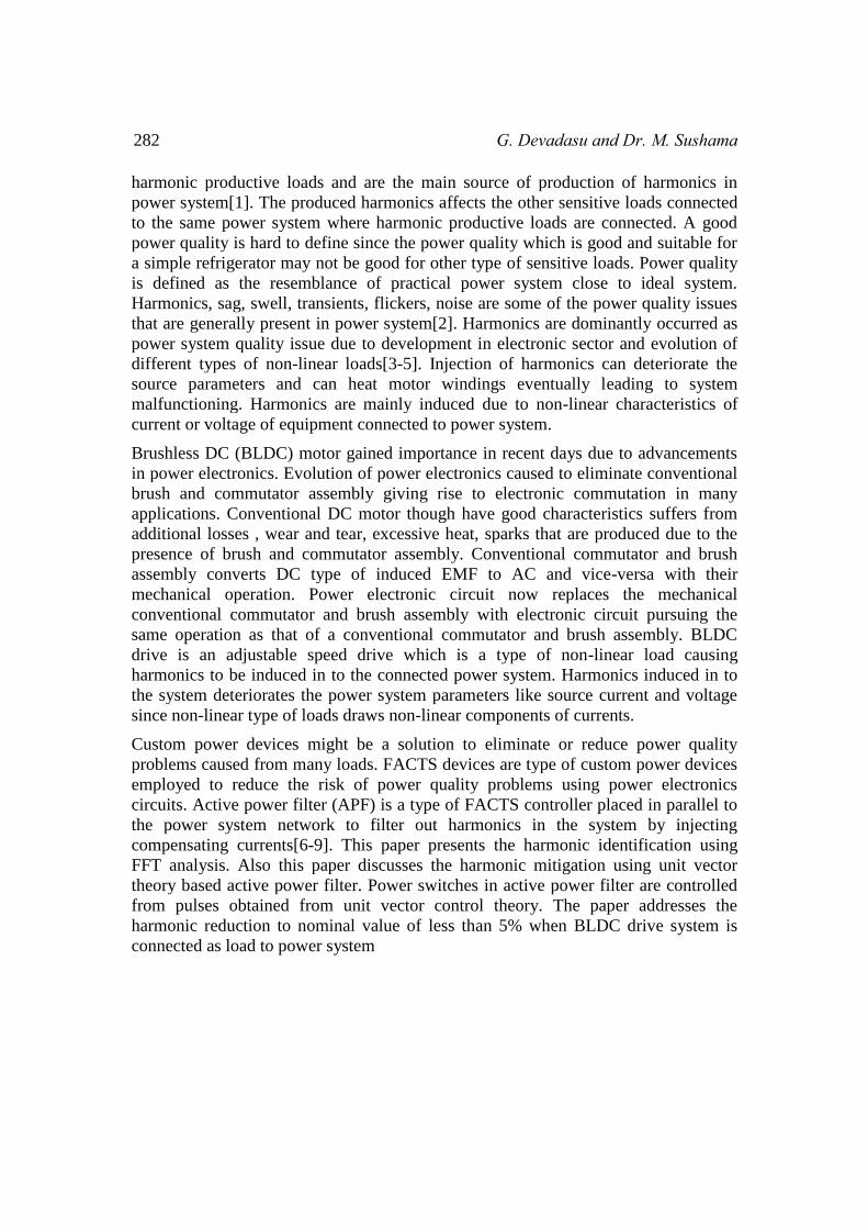
3. FFT ALGORITHM FOR IDENTIFICATION OF HARMONICS
Process to FFT Block
Load RMS Current into
MATLAB file
Test for Harmonics
Test for
Harmonics < 5%
Test for
Harmonics > 5%
Read Load Current
Display Result
Linear Load
Display Result
Non-Linear Load
Fig.3. Flow chart for Harmonic Identification using FFT analysis.
The exactness of custom power device can be assessed with the identification of
harmonics. Many methods are available to identify the harmonics in power system
network but in this paper FFT analysis was used for quick response and also the FFT
analysis is simple in implementation. FFT algorithms are based on fundamental of
discrete Fourier computation. Measuring the harmonic value, harmonic identification
exporting the values to Simulating file is discussed in detail in flow chart.
The algorithm for identification of harmonics using FFT analysis was depicted in
figure 3. Initially the load current is sensed and the read load currents are sent to FFT
block. The RMS component of current is loaded in to the MATLAB file and the
loaded currents are tested for harmonics. If the test result of harmonics measures the
harmonic content less than 5%, the FFT window displays result that the load is linear
load. If the test result of harmonics measures the harmonic content more than 5%, the
FFT window displays result that the load is non-linear load.
Harmonic Identification Using FFT and Harmonics Mitigation with Unit Vector 285
Vdcact
2/3(VLa^2+VLb^2+VLc^2) Vmax
+- PI Vdcref
+-
Isabcact
Isabcref
Hysterisis
control
Gate
pulses
VLabc Imag
Sin wt
Sin (wt-120)
Sin (wt-240)
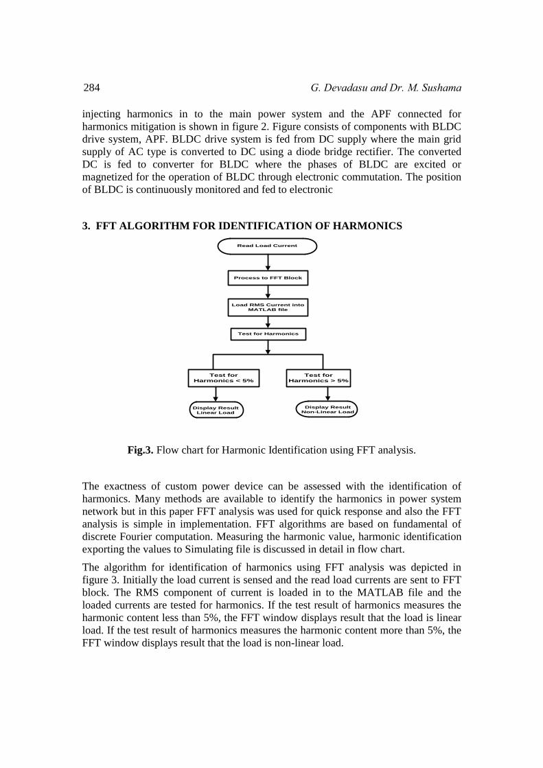
Fig.4: Unit vector control theory for APF
Conversion of time domain to frequency domain is possible with Fourier transforms.
Fourier series is used when the wave is periodical to calculate the magnitudes and
phases of harmonic component and fundamental component. FFT usage can give fast
and quick response which is essential in many applications and also the
implementation of FFT is very simple.
4. APF FOR HARMONIC MITIGATION AND ITS CONTROL
The system configuration with BLDC motor drive injecting harmonics in to the
connected power system and with active power filter (APF) for harmonic mitigation
was shown in figure 2. The control circuit to produce pulses to APF power switches
was shown in figure 4. Initially the line voltage is sent to generate unit vectors by
generating maximum value from line voltage. The obtained maximum value is
divided and originates sin wt from line value. Similarly sinusoidal phases of three
phases were obtained. The DC link actual voltage is compared with reference DC link
voltage and the error is fed to PI controller to obtain current magnitude signal which
is then multiplied to three unit vectors. The obtained current signals are then
compared to reference current signals and the error is fed to hysteresis current
controller to produce pulses for power switches of APF thus producing gate pulses.
Coupled
inductance
Three-phase
source
L
L
L
Diode bridge
rectifier
L L L
S1 S3 S5
S2S6S4
Vdc
S1' S3' S5'
S2'S6'S4'
Vdc
BLDC
Motor
Commutator
Vdcact
2/3(VLa^2+VLb^2+VLc^2) Vmax
+- PI Vdcref
+-
Isabcact
Isabcref
Hysterisis
control
Gate
pulses
VLabc Imag
Sin wt
Sin (wt-120)
Sin (wt-240)
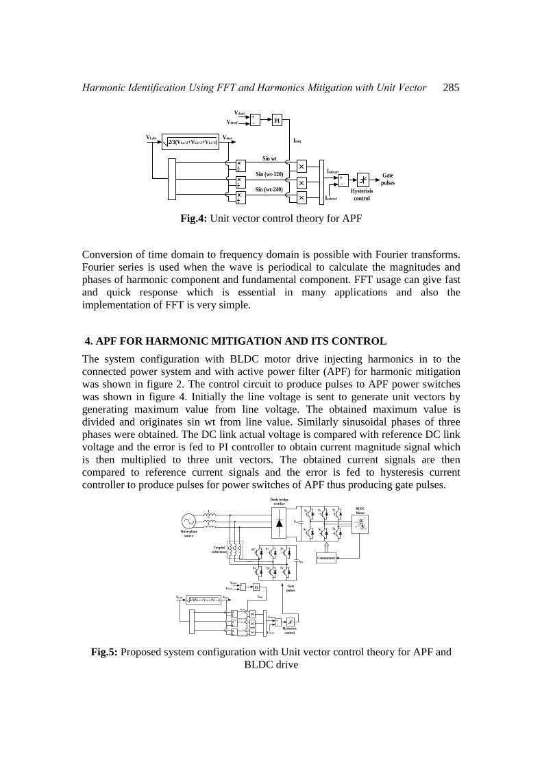
Fig.5: Proposed system configuration with Unit vector control theory for APF and
BLDC drive
286 G. Devadasu and Dr. M. Sushama
Figure 5 shows the proposed system for harmonic mitigation using APF controlled
with unit vector control theory and also BLDC drive system connected to system
injecting harmonics.
5. RESULTS AND DISCUSSIONS
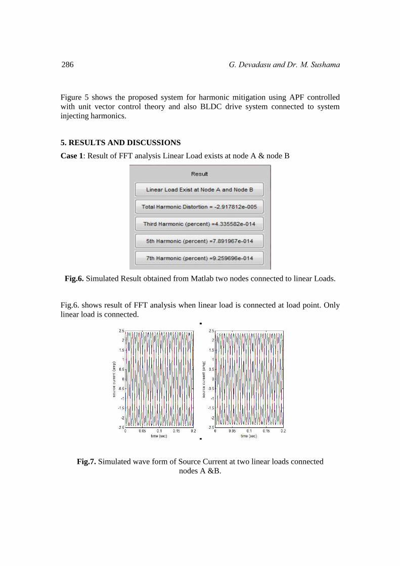
Case 1: Result of FFT analysis Linear Load exists at node A & node B
Fig.6. Simulated Result obtained from Matlab two nodes connected to linear Loads.
Fig.6. shows result of FFT analysis when linear load is connected at load point. Only
linear load is connected.
Fig.7. Simulated wave form of Source Current at two linear loads connected
nodes A &B.
Harmonic Identification Using FFT and Harmonics Mitigation with Unit Vector 287
Figure 7 illustrates the source current of linear loads connected at load point when
only linear type of loads is connected.
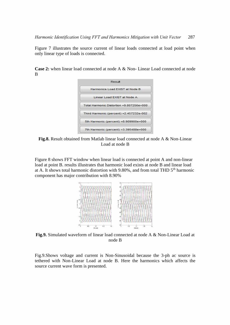
Case 2: when linear load connected at node A & Non- Linear Load connected at node
B
Fig.8. Result obtained from Matlab linear load connected at node A & Non-Linear
Load at node B
Figure 8 shows FFT window when linear load is connected at point A and non-linear
load at point B. results illustrates that harmonic load exists at node B and linear load
at A. It shows total harmonic distortion with 9.80%, and from total THD 5th harmonic
component has major contribution with 8.90%
Fig.9. Simulated waveform of linear load connected at node A & Non-Linear Load at
node B
Fig.9.Shows voltage and current is Non-Sinusoidal because the 3-ph ac source is
tethered with Non-Linear Load at node B. Here the harmonics which affects the
source current wave form is presented.

288 G. Devadasu and Dr. M. Sushama
Case 3: when linear load connected at node B & Non- Linear Load connected at
node A
Fig.10. Result obtained from Matlab linear load connected at node B & Non-Linear
Load at node A
Fig.10. Shows that non-linear load affects the voltage and currents with harmonics at
node A. linear load could not affect at node B it is identified from FFT analysis. The
Total Harmonic Distortion = 10.55% at α= 00. The 5th order harmonic component has
major contribution with 9.58%.
Fig.11. Simulated wave form of linear load connected at node B & Non-Linear Load
at node A
Fig.11.Shows voltage and current waveform with Non-Linear Load and linear load is
connected at respective nodes of A and B.
Harmonic Identification Using FFT and Harmonics Mitigation with Unit Vector 289
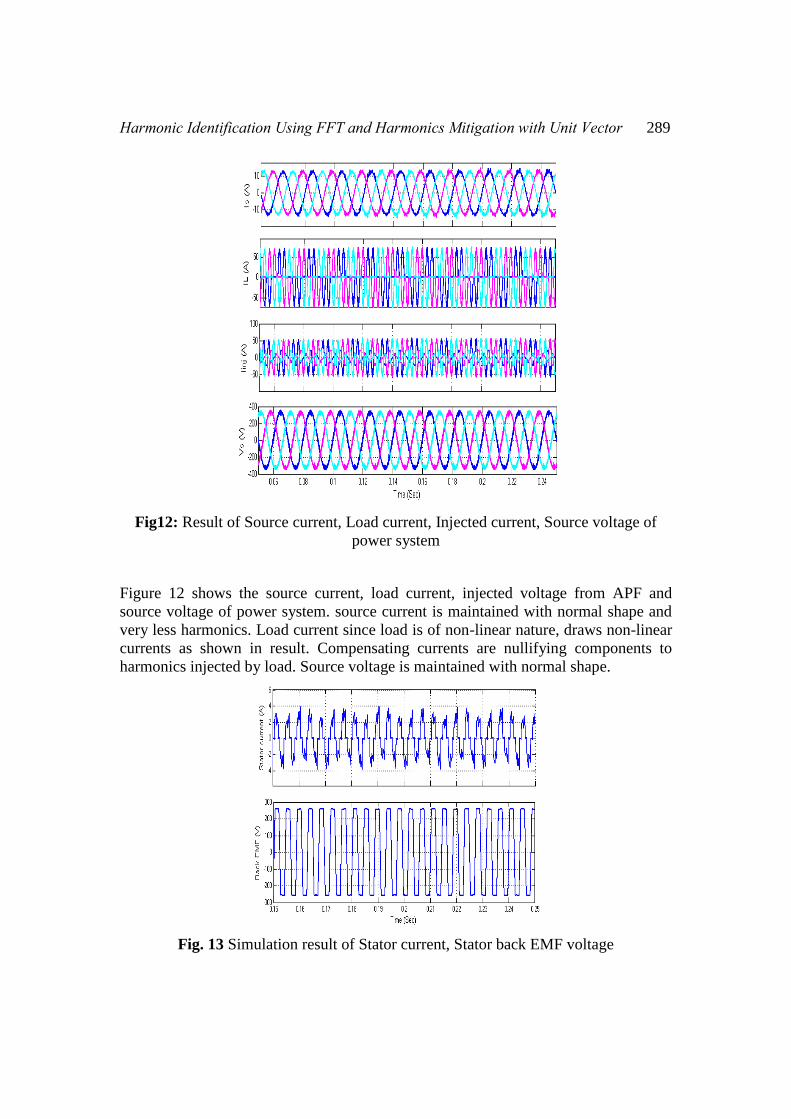
Fig12: Result of Source current, Load current, Injected current, Source voltage of
power system
Figure 12 shows the source current, load current, injected voltage from APF and
source voltage of power system. source current is maintained with normal shape and
very less harmonics. Load current since load is of non-linear nature, draws non-linear
currents as shown in result. Compensating currents are nullifying components to
harmonics injected by load. Source voltage is maintained with normal shape.
Fig. 13 Simulation result of Stator current, Stator back EMF voltage
290 G. Devadasu and Dr. M. Sushama
Figure 13 shows simulation result of stator current and stator back EMF of BLDC
motor. Stator current of BLDC is non-linear in shape and back EMF is trapezoidal in
shape.
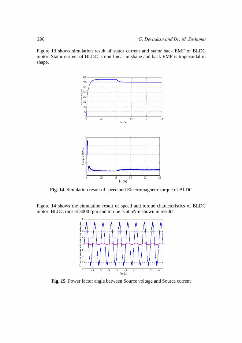
Fig. 14 Simulation result of speed and Electromagnetic torque of BLDC
Figure 14 shows the simulation result of speed and torque characteristics of BLDC
motor. BLDC runs at 3000 rpm and torque is at 5Nm shown in results.
Fig. 15 Power factor angle between Source voltage and Source current
Harmonic Identification Using FFT and Harmonics Mitigation with Unit Vector 291
Figure 15 shows the power factor angle between source voltage and current. The
power factor angle is almost zero indicating power factor is maintained nearer to
unity.
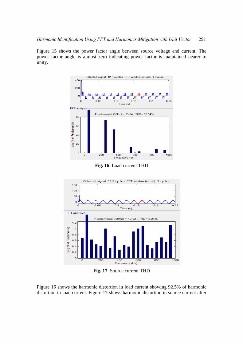
Fig. 16 Load current THD
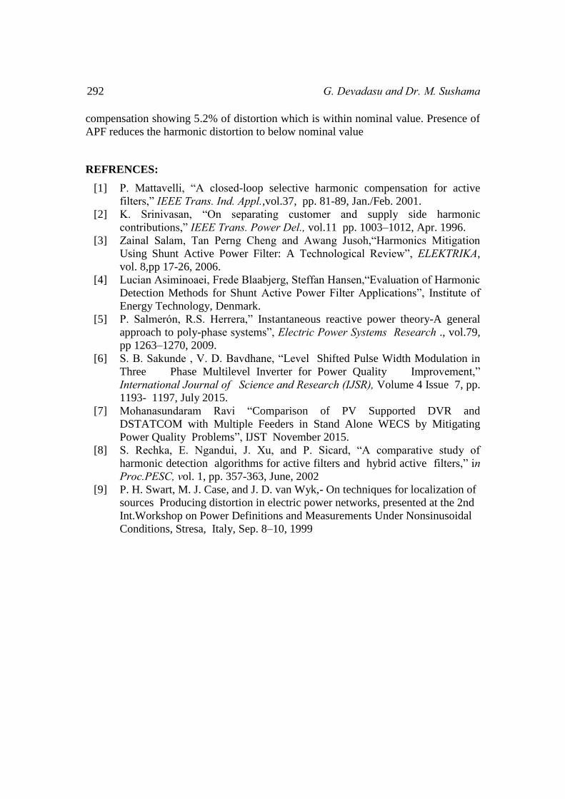
Fig. 17 Source current THD
Figure 16 shows the harmonic distortion in load current showing 92.5% of harmonic
distortion in load current. Figure 17 shows harmonic distortion in source current after
292 G. Devadasu and Dr. M. Sushama
compensation showing 5.2% of distortion which is within nominal value. Presence of
APF reduces the harmonic distortion to below nominal value
REFRENCES:
[1] P. Mattavelli, “A closed-loop selective harmonic compensation for active
filters,” IEEE Trans. Ind. Appl.,vol.37, pp. 81-89, Jan./Feb. 2001.
[2] K. Srinivasan, “On separating customer and supply side harmonic
contributions,” IEEE Trans. Power Del., vol.11 pp. 1003–1012, Apr. 1996.
[3] Zainal Salam, Tan Perng Cheng and Awang Jusoh,“Harmonics Mitigation
Using Shunt Active Power Filter: A Technological Review”, ELEKTRIKA,
vol. 8,pp 17-26, 2006.
[4] Lucian Asiminoaei, Frede Blaabjerg, Steffan Hansen,“Evaluation of Harmonic
Detection Methods for Shunt Active Power Filter Applications”, Institute of
Energy Technology, Denmark.
[5] P. Salmerón, R.S. Herrera,” Instantaneous reactive power theory-A general
approach to poly-phase systems”, Electric Power Systems Research ., vol.79,
pp 1263–1270, 2009.
[6] S. B. Sakunde , V. D. Bavdhane, “Level Shifted Pulse Width Modulation in
Three Phase Multilevel Inverter for Power Quality Improvement,”
International Journal of Science and Research (IJSR), Volume 4 Issue 7, pp.
1193- 1197, July 2015. [7] Mohanasundaram Ravi “Comparison of PV Supported DVR and
DSTATCOM with Multiple Feeders in Stand Alone WECS by Mitigating
Power Quality Problems”, IJST November 2015.
[8] S. Rechka, E. Ngandui, J. Xu, and P. Sicard, “A comparative study of
harmonic detection algorithms for active filters and hybrid active filters,” in Proc.PESC, vol. 1, pp. 357-363, June, 2002
[9] P. H. Swart, M. J. Case, and J. D. van Wyk,- On techniques for localization of
sources Producing distortion in electric power networks, presented at the 2nd
Int.Workshop on Power Definitions and Measurements Under Nonsinusoidal
Conditions, Stresa, Italy, Sep. 8–10, 1999