harmer steel products co
TRANSCRIPT

www.HarmerSteel.com [email protected] © 2014 (503) 286-3691 FAX (503) 286-2097
Harmer Steel Products Co.www.HarmerSteel.com
Head Office
[email protected] N.W. Front Avenue
Portland, OR 97231Phone (503) 286-3691
Fax (503) 286-2097Toll Free (800) 286-3691
Southwest U.S. Midwest U.S. Eastern U.S.
Chowchilla, CA Sheridan, IL Eleanor, WVPhone (559) 665-2050 Phone (815) 274-7245 Phone (304) 936-1456Fax (559) 665-2055 Fax (844) 254-7245Toll Free (800) 767-9497 Toll Free (844) 255-7245
Harmer Steel Ltd.www.HarmerSteel.ca
Western Canada Eastern Canada
Delta, BC Winnipeg, MB Phone (604) 526-1133 Phone (204) 988-1800 Fax (604) 526-1477 Fax (204) 988-1805 Toll Free (888) 526-1134 Toll Free (888) 988-1801

(503) 286-3691 FAX (503) 286-2097 © 2014 www.HarmerSteel.com [email protected]
About This Catalog
This catalog contains information about Harmer Steel’s most frequently specified products, which are summarized in the Table of Contents.Basic information is given for each product. More detailed specifications,or data about custom and specialty items are available upon request.
For easy reference, this catalog is divided into five sections,(I) Tee Rails(II) Crane Rails(III) Crane Rail Fasteners(IV) Track Accessories and Tools(V) Frogs, Switches and Turnout Material
About Harmer Steel
Harmer Steel Products Co. began in 1928 as a supplier of rail andtrack accessories. Today, as one of North America’s leading railproducts suppliers, Harmer maintains a large inventory andprovides a wide variety of rail fabrication services. Both new and usedrail and accessories are stocked for prompt shipment to railroads,mines, crane jobs, and other industries.
The people at Harmer Steel are a dedicated team of professionalswho work together to ensure that your order is handled promptly andwith the utmost care.
Be sure to visit our website at www.HarmerSteel.com orwww.HarmerSteel.ca. Our sales department can be reached via email:[email protected]
A knowledgeable sales representative will promptly assist you.
George WebbPresident
www.HarmerSteel.com [email protected] © 2010 (503) 286-3691 FAX (503) 286-2097
Table of Contents
Section I – TEE RAILS Introduction - New and Relay ............................................................................................I-1 Splice Bars, Curved Rails .................................................................................................I-2 Table of Tee Rail Sections .................................................................................... I-3 and I-4 Tee Rails 12-lb. to 141-lb. ................................................................................... I-5 thru I-21
Section II – CRANE RAILS American Crane Rails ......................................................................................................II-1 Crane Rails 104-lb. to 175-lb. ............................................................................. II-2 thru II-6 European Crane Rail .......................................................................................................II-7 Weight and Measure Conversion Table ...........................................................................II-8
Section III – CRANE RAIL FASTENERS Hook Bolts ......................................................................................................................III-1 One-Piece Rail Clips ........................................................................................ III-2 and III-3 Crane Stops ....................................................................................................................III-3 Soft-Mount Crane Rail Systems ......................................................................................III-4 Soft-Mount Crane Rail System Clips ..............................................................................III-5 Crane Rail Pads, Girder Tie-Back Linkages ....................................................................III-6 Application Data Sheet ...................................................................................................III-7 Rail Clamps for Crane Rails ............................................................................. III-8 and III-9 Rail Clamps for Tee Rails ..............................................................................................III-10
Section IV – TRACK ACCESSORIES AND TOOLS Gage Rods ..................................................................................................................... IV-1 Bolts and Washers ......................................................................................................... IV-2 Spikes ............................................................................................................................ IV-3 Rail Anchors, Tie Plates ................................................................................................. IV-4 Direct Fixation Tie Plates, Steel Ties ............................................................................. IV-5 Steel Mine Ties ................................................................................................ IV-6 thru IV-8 Wood Ties, Tie Plugs ..................................................................................................... IV-9 Compromise and Insulated Joint Bars ......................................................................... IV-10 Portable Track Signs .................................................................................................... IV-11 Bumping Posts ............................................................................................. IV-12 and IV-13 Derails .......................................................................................................... IV-14 and IV-15 Adjustable Derail, Rerailers ......................................................................................... IV-16 Wheel Stops ................................................................................................................ IV-17 Wheel Chocks .............................................................................................................. IV-18 Track Repair Equipment ............................................................................................... IV-19 Track Gaging Tools ....................................................................................................... IV-20 Rail Benders ................................................................................................................ IV-21 Track Tools ................................................................................................... IV-22 and IV-23 Track Jacks, Track Liners ............................................................................................. IV-24
Section V – FROGS, SWITCHES, TURNOUT MATERIAL Introduction - Turnout Diagram ....................................................................................... V-1 Determining Frog Number .............................................................................................. V-2 Frogs for Light Rails ........................................................................................................ V-3 Solid Manganese Self-Guarded Frogs ............................................................................ V-4 Railbound Manganese Frogs .......................................................................................... V-5
continued

(503) 286-3691 FAX (503) 286-2097 © 2010 www.HarmerSteel.com [email protected]
Rigid Bolted and Manganese Flat-Top Frogs .................................................................. V-6 Guard Rails ..................................................................................................................... V-7 One-Piece Guard Rails ................................................................................................... V-8 Switch Point Details ........................................................................................................ V-9 16’6” Straight Split Switch with Graduated Risers.......................................... V-10 and V-11 Switch Point Protectors and Guards ............................................................................. V-12 Preassembled Light Rail Turnouts ................................................................................ V-13 Heel Joints .................................................................................................................... V-14 Plates and Braces ......................................................................................................... V-15 Twin Tie Plates ............................................................................................... V-16 and V-17 Switch Stands ................................................................................................ V-18 and V-19 Switch Stands for Light Rails ........................................................................................ V-20 American Mining Congress Turnout Data ...................................................... V-21 thru V-28
Table of Contents (cont.)
Section V – FROGS, SWITCHES, TURNOUT MATERIAL (cont.)

TEE RAILS

I – 1(503) 286-3691 FAX (503) 286-2097 © 2010 www.HarmerSteel.com [email protected]
TEE RAILS
This portion of our catalog provides a comprehensive list of “tee rails” available from Harmer Steel. All of the rail sections shown on pages I-5 through I-21 are standard ASCE (American Society of Civil Engineers), ARA–A (American Railway Association Type A), and AREMA (American Railway Engineering and Maintenance-of-Way Association) designs mostly in current manufacture. ASCE rails are primarily designed for light overhead cranes, mining track, automated warehouse retrieval systems, and other industrial applications. ARA–A and AREMA rails are primarily designed for railroad tracks, including sidings and spur tracks. Rail weighing 60 pounds per yard or more is normally manufactured to ASTM A–1 or AREMA specifications.
Relay Rail
In addition to new rail, Harmer Steel also stocks a wide range of good quality used rail. Used rail in good enough condition to be re-laid is called “relay rail.” Relay rail is often used for industrial sidings and spur tracks, where the slower speed and infrequent traffic do not warrant the expense of new rail. Relay rail is graded and classified according to the type and number of flaws and the amount of wear exhibited. Harmer Steel takes pride in grading relay rail carefully to ensure that all material shipped will meet each customer’s exact specifications.
There are several different types of rail wear that are usually measured when grading relay rail. “Top wear” and “side wear” are measured by comparing the difference between the height and head-width of the relay rail with a newly manufactured rail section of the same weight and size. (Side wear is sometimes referred to as “gage wear” or “curve wear”). “End batter” is the term for the difference in height measured at the end of a rail and the height of the same rail measured behind the joint. “Flow” is the term used to describe a small lip sticking out at the side of the rail head. Flow can be present on one or both sides of the head, however, the highest quality relay rail exhibits only a small amount of flow on one side only. Relay rail with flow on one side is often turned around when re-laid so that the lip is then on the field side (outside) of the track.
Relay rail is generally classified as “Number One” or “Number Two Relay.” The definitions of Number One and Number Two Relay vary somewhat according to whose specifications are used. Different railroads and associations have developed different classification systems for grading relay rail. Generally speaking, Number One Relay allows a maximum of 1/8” top wear for rails up to and including 115–lb., a maximum of 3/16” top wear for rails between 119 & 133, and 1/4" for rails136–lb. and heavier. Please contact your Harmer representative for more complete specifications.
In addition to the rail sections shown on pages I-5 to I-21, a great number of relay rail sections, even those not currently manufactured, can be supplied by Harmer Steel. The table on pages I-3 and I-4 provides an extensive list of new and older rail sections.

I – 2www.HarmerSteel.com [email protected] © 2010 (503) 286-3691 FAX (503) 286-2097
SPLICE BARS, CuRvEd RAILS
Splice Bars
Often rails are joined together by welding, but most rail for industry use is connected by means of a bolted splice. There are usually two or three holes drilled in the end of the rails for these splices. The hole spacing pattern is called the “drilling” and is measured from the end of the rail to the center of the first hole, and from the center of the first hole to the center of the second hole, etc. Thus a drilling might be 2-1/2” X 5” or 3-1/2” X 6” X 6”.
The standard drillings for tee rails and corresponding splice bars provide for a 1/8” gap between rail ends. This is standard construction for railroad track and light crane service. For best service in bolted splices for rails in crane service, it is recommended that “tight joints” be stipulated. (See page II-1 for a description of a tight joint.) Although tight joints are not standard for tee rails, Harmer Steel can supply tight joints in the ASCE sections from 30-lb. to 85-lb.
The term “splice bar” refers to only one type of connector bar and frequently is confused with other types. The drawings below provide clarification of the proper term for each type of connector bar.
Splice Bars Angle Bars Joint Bars
Ball Out Ball In Ball up Specify Inside Diameter Specify Outside Diameter Specify Centerline Diameter of Head
Curved Rail
Curving of tee rails and crane rails is available in a variety of ways to suit various applications.

I – 3(503) 286-3691 FAX (503) 286-2097 © 2010 www.HarmerSteel.com [email protected]
TEE RAIL SECTIOnS –– dATA
Nominal Dimensions in Inches Weight Type Per Yard of Rail HT BW HW W HD FD BD E Section Designation
12 lb. ASCE 2 2 1 3/16 9/16 1-3/32 11/32 57/64 1240 12 AS – 16 lb. ASCE 2-3/8 2-3/8 1-11/64 7/32 41/64 1-23/64 3/8 1-1/16 1640 16 AS – 20 lb. ASCE 2-5/8 2-5/8 1-11/32 1/4 23/32 1-15/32 7/16 1-11/64 2040 20 AS – 25 lb. ASCE 2-3/4 2-3/4 1-1/2 19/64 25/32 1-31/64 31/64 1-15/64 2540 25 AS – 30 lb. ASCE 3-1/8 3-1/8 1-11/16 21/64 7/8 1-23/32 17/32 1-25/64 3040 30 AS – 35 lb. ASCE 3-5/16 3-5/16 1-3/4 23/64 61/64 1-25/32 37/64 1-15/32 3540 35 AS – 40 lb. ASCE 3-1/2 3-1/2 1-7/8 25/64 1-1/64 1-55/64 5/8 1-9/16 4040 40 AS – 45 lb. ASCE 3-11/16 3-11/16 2 27/64 1-1/16 1-31/32 21/32 1-41/64 4540 45 AS – 50 lb. ASCE 3-7/8 3-7/8 2-1/8 7/16 1-1/8 2-1/16 11/16 1-23/32 5040 50 AS – 55 lb. ASCE 4-1/16 4-1/16 2-1/4 15/32 1-11/64 2-11/64 23/32 1-103/128 5540 55 AS – 56 lb. MISC. 4 3-27/32 2-5/16 11/32 1-13/32 1-29/32 11/16 1-41/64 5607 MISC. 4-1/4 4-1/8 2-1/4 3/8 1-27/64 2-1/8 45/64 1-3/4 5633 56-M 5616 60 lb. ASCE 4-1/4 4-1/4 2-3/8 31/64 1-7/32 2-17/64 49/64 1-29/32 6040 60 AS 603 ARA-A 4-1/2 4 2-1/4 15/32 1-15/64 2-29/64 13/16 2-17/64 6020 60 RA 602 MISC. 4-1/4 4-1/16 2-5/16 1/2 2-1/8 6001 6051 65 lb. ASCE 4-7/16 4-7/16 2-13/32 1/2 1-9/32 2-3/8 25/32 1-31/32 6540 65 AS 653 70 lb. ASCE 4-5/8 4-5/8 2-7/16 33/64 1-11/32 2-15/32 13/16 2-3/64 7040 70 AS 701 72 lb. C&NW 4-3/4 4-3/4 2-3/8 9/16 1-13/32 2-1/2 27/32 2-3/32 7201 72 NP 7250 75 lb. ASCE 4-13/16 4-13/16 2-15/32 17/32 1-27/64 2-35/64 27/32 2-15/128 7540 75 AS 753 MO. PAC. 4-3/4 4-3/4 2-9/16 9/16 1-7/16 2-15/32 27/32 2-5/64 7550 75 MP – S. PAC. 4-15/16 4-7/16 2-7/16 33/64 1-3/8 2-5/8 15/16 2-1/4 7524 75 SP 754 U. PAC. 5 5 2-9/16 1/2 1-3/8 2-13/16 13/16 2-5/8 7523 75 CS 754 U. PAC. 4-15/16 4-7/16 2-7/16 33/64 1-3/8 2-5/8 15/16 2-1/2 7524 75 CSR 757 80 lb. ASCE 5 5 2-1/2 35/64 1-1/2 2-5/8 7/8 2-3/16 8040 80 AS 800 DUDLEY 5-1/8 5 2-21/32 17/32 1-1/2 2-3/4 7/8 2-1/4 8022 80 DY – 85 lb. ASCE 5-3/16 5-3/16 2-9/16 9/16 1-35/64 2-3/4 57/64 2-17/64 8540 85 AS 851 CAN. PAC. 5-1/8 5 2-1/2 9/16 1-7/16 2-11/16 1 2-11/32 8524 85 CP – CB&Q 5-3/16 5-3/16 2-21/32 9/16 1-35/64 2-3/4 57/64 2-17/64 8543 85 CB 852 GRT. NO. 5 5 2-21/32 21/32 1-19/32 2-1/2 29/32 2-5/32 8509 85 GN 8553 MO. PAC. 5-7/32 5-1/4 2-15/32 75/128 1-3/4 2-39/64 55/64 2-21/128 8550 – – PS 5-1/8 4-5/8 2-1/2 17/32 1-21/32 2-15/32 1 2-15/64 8531 85 PS – PRR 5 5 2-9/16 17/32 1-3/4 2-3/8 7/8 2-1/16 8533 85 PR – SOO LINE 5-3/8 4-7/8 2-1/2 9/16 1-15/32 2-29/32 1 2-29/64 8520 – – 90 lb. ASCE 5-3/8 5-3/8 2-5/8 9/16 1-35/64 2-55/64 59/64 2-45/128 9040 90 AS – ARA-A 5-5/8 5-1/8 2-9/16 9/16 1-15/32 3-5/32 1 2-37/64 9020 90 RA 902 ARA-B 5-17/64 4-49/64 2-9/16 9/16 1-39/64 2-5/8 1-1/32 2-11/32 9030 90 RB 905 AT&SF 5-5/8 5-3/16 2-9/16 9/16 1-15/32 3-5/32 1 2-37/64 9021 90 SF 903 C&NW 5-17/32 5-3/32 2-1/2 1/2 1-17/32 2-31/32 1-1/32 2-23/64 9035 90 OM – D&RG 5-1/2 5-1/8 2-9/16 9/16 1-5/8 2-7/8 1 2-5/8 – – 906 GRT. NO. 5-3/8 5 2-5/8 9/16 1-15/32 2-7/8 1-1/32 2-15/32 9024 90 GN 904 INTRBGH 5 5 2-7/8 11/16 1-25/32 2-11/32 7/8 2-3/64 9050 90 RT – U. PAC. 5-3/4 5-3/8 2-3/4 17/32 1-1/2 3-3/8 7/8 2-9/16 9023 90 UP 901 DUDLEY 5-1/2 5 2-21/32 9/16 1-1/2 3-1/32 31/32 2-3/8 – 90 DY –
(Dimensions for Tee Rail Data Table)
HT – HeightBW – Width of BaseHW – Width of HeadW – Web (at center point)HD – Depth of HeadFD – FishingBD – Depth of BaseE – Bolt Hole Elevation
HW
HD
FD
BD
BW
HT W
E

I – 4www.HarmerSteel.com [email protected] © 2010 (503) 286-3691 FAX (503) 286-2097
TEE RAIL SECTIOnS –– dATA
Identifying Rail Sections
The weight and type of most rails can easily be identified by referring to the dimensional diagrams on pages I-5 through I-21 in this catalog. For these and other sections, the tee rail sections data table on the preceeding page and above lists basic dimensions and identifies mill marks usually rolled on rail web.
If a special section is not listed, simply place a piece of paper against the rail end, and impress its outline into the paper by pressing your fingers against the rail edges. Take note of the width of the base, rail height, and head dimensions as well as all numbers and letters on the side of the rail. With this information, Harmer can determine the best rail to meet your individual requirements.
Nominal Dimensions in Inches Weight Type Per Yard of Rail HT BW HW W HD FD BD E Section Designation
100 lb. ASCE 5-3/4 5-3/4 2-3/4 9/16 1-45/64 3-5/64 31/32 2-65/128 10040 100 AS – PS 5-11/16 5 2-43/64 9/16 1-13/16 2-25/32 1-3/32 2-31/64 10031 100 PS – PRR 5-1/2 5-1/2 2-13/16 5/8 1-7/8 2-11/16 15/16 2-9/32 10033 100 PR – ARA-A 6 5-1/2 2-3/4 9/16 1-9/16 3-3/8 1-1/16 2-3/4 10020 100 RA 1003 ARA-B 5-41/64 5-9/64 2-21/32 9/16 1-45/64 2-55/64 1-5/64 2-65/128 10030 100 RB 1002 AREMA 6 5-3/8 2-11/16 9/16 1-21/32 3-9/32 1-1/16 2-45/64 10025 100 RE 10025 ARA-A HF 6-5/32 5-1/2 2-11/16 9/16 1-23/32 3-3/8 1-1/16 2-15/16 – 100 RA-HF – AREA HF 6-1/16 5-3/8 2-39/64 9/16 1-23/32 3-9/32 1-1/16 2-31/32 10027 100 RE-HF – C&NW 5-45/64 5-9/64 2-9/16 9/16 1-39/64 2-61/64 1-9/64 2-79/128 10035 100 DM – GRT. NO. 5-3/4 5 2-3/4 9/16 1-5/8 3 1-1/8 2-5/8 10036 100 GN – INTRBGH 5-3/4 5-3/4 2-7/8 9/16 1-45/64 3-5/64 31/32 2-65/128 10005 100 RT – NY.NH&H 6 5-1/2 2-3/4 19/32 1-23/32 3-11/32 15/16 2-39/64 10034 100 NH – READING 5-5/8 5-3/8 2-21/32 9/16 1-45/64 2-55/64 1-1/16 2-63/128 10032 100 RG – 101 lb. DL&W 5-7/16 5-3/8 2-3/4 5/8 1-23/32 2-11/16 1-1/32 2-3/8 10133 101 DL – 105 lb. DL&W 6 5-3/8 2-3/4 5/8 1-23/32 3-1/4 1-1/32 2-21/32 10533 105 DL – DUDLEY 6 5-1/2 3 5/8 1-5/8 3-13/32 31/32 2-43/64 10524 105 DY – 110 lb. AREMA 6-1/4 5-1/2 2-25/32 19/32 1-23/32 3-13/32 1-1/8 2-53/64 11025 110 RE 1100 GRT. NO. 6-1/2 5-1/2 2-3/4 19/32 1-5/8 3-3/4 1-1/8 3 11036 110 GN – LE. VAL. 6 5-1/2 2-7/8 19/32 1-7/8 3-1/16 1-1/16 2-19/32 11033 110 LV – 112 lb. AREMA 6-5/8 5-1/2 2-23/32 19/32 1-11/16 3-13/16 1-1/8 2-7/8 11225 112 RE 1121 TR. 6-3/4 5-1/2 2-1/2 5/8 1-3/4 3-7/8 1-1/8 3-1/8 11229 – 1122 113 lb. HF 6-13/16 5-1/2 2-11/16 19/32 – 3-13/16 – – – 113 HF – 115 lb. AREMA 6-5/8 5-1/2 2-23/32 5/8 1-11/16 3-13/16 1-1/8 2-7/8 11525 115 RE 1150 DUDLEY 6-1/2 5-1/2 3 5/8 1-11/16 3-3/4 1-1/16 3-3/8 11522 115 DY – 119 lb. AREMA 6-13/16 5-1/2 2-21/32 5/8 1-7/8 3-13/16 1-1/8 2-7/8 11925 119 RE – 122 lb. CHESSIE 6-25/32 6 2-15/16 21/32 1-15/16 3-39/64 1-15/64 3-21/64 – 122 CB – 127 lb. DUDLEY 7 6-1/4 3 21/32 1-11/16 4-5/32 1-5/32 3-1/8 12723 123 DYM – 130 lb. PS 6-5/8 5-1/2 3 11/16 2 3-13/32 1-7/32 2-3/4 13031 130 PS – AREMA 6-3/4 6 2-15/16 21/32 1-27/32 3-11/16 1-7/32 3-1/16 13025 130 RE 1300 131 lb. AREMA 7-1/8 6 3 21/32 1-3/4 4-3/16 1-3/16 3-1/4 13128 131 RE 1311 132 lb. AREMA 7-1/8 6 3 21/32 1-3/4 4-3/16 1-3/16 3-3/32 13225 132 RE 1321 133 lb. AREMA 7-1/16 6 3 11/16 1-15/16 3-15/16 1-3/16 3 13325 133 RE 1330 136 lb. AREMA 7-5/16 6 2-15/16 11/16 1-15/16 4-3/16 1-3/16 3-3/32 13625 136 RE – 140 lb. AREMA 7-5/16 6 3 3/4 2-1/16 4-1/16 1-3/16 3 14025 140 RE – 141 lb. AREMA 7-7/16 6 3-1/16 11/16 2-5/32 4-3/32 1-3/16 3-3/32 14128 141 RE – 152 lb. PS 8 6-3/4 3 11/16 1-27/32 4-7/8 1-9/32 3-3/4 15222 152 PS – 155 lb. PS 8 6-3/4 3 3/4 2-1/16 4-21/32 1-9/32 3-3/8 15531 155 PS –

I – 5(503) 286-3691 FAX (503) 286-2097 © 2010 www.HarmerSteel.com [email protected]
12–lb. ASCE
Rail Type: 12 AS Section number: 1240 nominal Weight: 12 lbs/yd
Standard Length: 30’ Standard drilling: 2” X 4” with 5/8” dia. holes
Splice Bar Length: 16-1/8” Splice Bar Weight: 2 lbs/pr with hardware: 3 lbs/pr Track Bolt: 1/2” X 1-3/4”
Area in2: 1.18Section Modulus in3: Head: .58
Moment ofInertia in4: .55
Head 1"
Base 2"
Shown Actual Size
2"1-3/32"
13 °57/64"
57/64"
9/16"
3/16"
1/16"
11/32"
12" R
12" R
3/16"
3/16"
13°
5/32"
Bolt Hole

I – 6www.HarmerSteel.com [email protected] © 2010 (503) 286-3691 FAX (503) 286-2097
20–lb. ASCE
Rail Type: 20 AS Section number: 2040 nominal Weight: 20 lbs/yd
Standard Length: 30’ (20’ may also be available) Standard drilling: 2” X 4” with 5/8” dia. holes
Splice Bar Length: 16-1/8” Splice Bar Weight: 6 lbs/pr with hardware: 7 lbs/pr Track Bolt: 1/2” X 2”
Area in2: 2.00Section Modulus in3: Head: 1.41
Moment ofInertia in4: 1.93
1-15/32"
13°
1-11/64"1-11/64"
23/32" 1/4"
1/16"
3/16"
7/16"
12" R Bolt Hole
Head 1-11/32"
Base 2-5/8"
Shown Actual Size
2-5/8"
12" R
3/16"
13°
1/4"

I – 7(503) 286-3691 FAX (503) 286-2097 © 2010 www.HarmerSteel.com [email protected]
25–lb. ASCE
Rail Type: 25 AS Section number: 2540 nominal Weight: 25 lbs/yd
Standard Length: 30’ (40’ may also be available) Standard drilling: 2” X 4” with 5/8” dia. holes
Splice Bar Length: 16-1/8” Splice Bar Weight: 6 lbs/pr with hardware: 7 lbs/pr Track Bolt: 1/2” X 2”
Area in2: 2.4Section Modulus in3: Head: 1.76
Moment ofInertia in4: 2.5
Head 1-1/2"Shown Actual Size
1-31/64"
13°
13°
1-15/64"1-15/64"
25/32" 1/4"
1/16"
31/64"
12" R
12" R
1/4"
1/4"
2-3/4"19/64"
Bolt Hole
Base 2-3/4"

I – 8www.HarmerSteel.com [email protected] © 2010 (503) 286-3691 FAX (503) 286-2097
30–lb. ASCE
Rail Type: 30 AS Section number: 3040 nominal Weight: 30 lbs/yd
Standard Length: 30’ (20’ and 40’ may also be available) Standard drilling: 2” X 4” with 3/4” dia. holes
Splice Bar Length: 16-1/8” Splice Bar Weight: 6 lbs/pr with hardware: 8 lbs/pr Track Bolt: 5/8” X 2-1/2”
Area in2: 3.00Section Modulus in3: Head: 2.55
Moment ofInertia in4: 4.10
Head 1-11/16"
Base 3-1/8"
Shown Actual Size
3-1/8"1-23/32"
13°
13°
1-25/64"1-25/64"
7/8"
1/4"
5/16"
1/16"
1/16" R
1/4"
21/64"
17/32"
12" R
12" R
1/16" R
Bolt Hole

I – 9(503) 286-3691 FAX (503) 286-2097 © 2010 www.HarmerSteel.com [email protected]
40–lb. ASCE
Rail Type: 40 AS Section number: 4040 nominal Weight: 40 lbs/yd
Standard Length: 20’, 30’ & 40’ Standard drilling: 2-1/2” X 5” with 7/8” dia. holes
Splice Bar Length: 20” Splice Bar Weight: 8 lbs/pr with hardware: 11 lbs/pr Track Bolt: 3/4” X 3-1/2”
Area in2: 3.94Section Modulus in3: Head: 3.59
Moment ofInertia in4: 6.54
Head 1-7/8"
Base 3-1/2"
Shown Actual Size
3-1/2"1-55/64"
13°
13°
1-9/16"1-9/16"
1-1/64"
1/4"
5/16"
1/16"
1/16" R
1/4"
25/64"
5/8"
12" R
12" R
1/16" R
Bolt Hole

I – 10www.HarmerSteel.com [email protected] © 2010 (503) 286-3691 FAX (503) 286-2097
Rail Type: 60 AS Section number: 6040 nominal Weight: 60 lbs/yd
Standard Length: 20’, 30’, 33’, & 40’ Standard drilling: 2-1/2” X 5” with 15/16” dia. holes
Splice Bar Length: 20” Splice Bar Weight: 13 lbs/pr with hardware: 16 lbs/pr Track Bolt: 3/4” X 4”
60–lb. ASCE
Area in2: 5.93Section Modulus in3: Head: 6.62 Base: 7.10
Moment ofInertia in4: 14.56
Head 2-3/8"
Base 4-1/4"
Shown Actual Size
4-1/4"2-17/64"
13°
13°
1-29/32"1-29/32"
1-7/32"
1/4"
5/16"
1/16"
1/16" R
1/4"
31/64"
49/64"
12" R
12" R
1/16" R
Bolt Hole

I – 11(503) 286-3691 FAX (503) 286-2097 © 2010 www.HarmerSteel.com [email protected]
80–lb. ASCE
Rail Type: 80 AS Section number: 8040 nominal Weight: 80 lbs/yd
Standard Length: 39’ Standard drilling: 2-1/2” X 5” with 1” dia. holes
Splice Bar Length: 24” Splice Bar Weight: 16 lbs/pr with hardware: 19 lbs/pr Track Bolt: 7/8” X 4-1/2”
Area in2: 7.86Section Modulus in3: Head: 10.07 Base: 11.08
Moment ofInertia in4: 26.38
Head 2-1/2"
Base 5"
Shown Actual Size
5"2-5/8"
2-3/16"
2-3/16"
1-1/2"
1/4"
1/16" R
1/4"
35/64"
7/8"
12" R
12" R
13°
13°
1/16" R
Bolt Hole
5/16"
1/16" 12" R

I – 12www.HarmerSteel.com [email protected] © 2010 (503) 286-3691 FAX (503) 286-2097
85–lb. ASCE
Rail Type: 85 AS Section number: 8540 nominal Weight: 85 lbs/yd
Standard Length: 39’ Standard drilling: 2-1/2” X 5” with 1” dia. holes
Splice Bar Length: 24” Splice Bar Weight: 18 lbs/pr with hardware: 23 lbs/pr Track Bolt: 7/8” X 4-1/2”
Area in2: 8.33Section Modulus in3: Head: 11.08 Base: 12.17
Moment ofInertia in4: 30.07
Head 2-9/16"
Base 5-3/16"
Shown Actual Size
5-3/16"
2-3/4"
2-17/64"2-17/64"
1-35/64"
1/4"
1/16" R
1/4"
9/16"
57/64"
12" R
12" R
13°
13 °
1/16" R
Bolt Hole
5/16"
1/16"
12" R

I – 13(503) 286-3691 FAX (503) 286-2097 © 2010 www.HarmerSteel.com [email protected]
90–lb. ARA–A
Area in2: 8.82Section Modulus in3: Head: 12.6 Base: 15.2
Moment ofInertia in4: 38.7
BOLT size MAY VARY DePeNDiNG ON BAR MANUFACTURe & TYPe OF WAsHeR UseD.
Head 2-9/16"
Base 5-1/8"
Shown Actual Size
5-5/8"
3-5/32"
2-37/64"
2-29/32"
1-15/32"
3/8"
1/16" R
3/8"
9/16"
1"
14" R
14" R
14" R14° 02"
14° 02 "
3° 34-1/2'
1/16" R
3/8"
Bolt Hole
1/16"
Rail Type: 90 RA Section number: 9020 nominal Weight: 90 lbs/yd
Standard Length: 39’ Standard drilling: 2-11/16” X 5-1/2” with 1-1/8” dia. holes
Joint & Angle Bar Lgth: 24” Angle Bar Weight: 60 lbs/pr with hardware: 67 lbs/pr Joint Bar Weight: 46 lbs/pr with hardware: 53 lbs/pr Track Bolt: 7/8” X 5”

I – 14www.HarmerSteel.com [email protected] © 2010 (503) 286-3691 FAX (503) 286-2097
100–lb. ARA–A
Area in2: 9.84Section Modulus in3: Head: 15.04 Base: 17.78
Moment ofInertia in4: 48.94
BOLT size MAY VARY DePeNDiNG ON BAR MANUFACTURe & TYPe OF WAsHeR UseD.
Head2-3/4"
Base5-1/2"
Shown Actual Size
6"
3-3/8"
2-3/4"2-15/16"
1-9/16"
3/8"
3/8"
1/16" R
3/8"
9/16"
1-1/16"
14" R
14" R
14" R14° 02 '
14° 02 '
3° 34-1/2'
1/16" R
Bolt Hole
1/16"
Rail Type: 100 RA Section number: 10020 nominal Weight: 100 lbs/yd
Standard Length: 39’ Standard drilling: 2-11/16” X 5-1/2” with 1-3/16” dia. holes
Joint Bar Length: 22” Joint Bar Weight: 54 lbs/pr with hardware: 62 lbs/pr Track Bolt: 1” X 5-1/2”

I – 15(503) 286-3691 FAX (503) 286-2097 © 2010 www.HarmerSteel.com [email protected]
100–lb. AREMA
BOLT size MAY VARY DePeNDiNG ON BAR MANUFACTURe & TYPe OF WAsHeR UseD.
Area in2: 9.95Section Modulus in3: Head: 15.1 Base: 17.8
Moment ofInertia in4: 49.0
Head2-11/16"
Base5-3/8"
Shown Actual Size
6"
3-9/32"
2-45/64"2-31/32"
1-21/32"
3/8"
1/16" R
5/8"
1-1/16"
14" R
14" R14° 02 '
14° 02 '
3° 34-1/2'
9/16"
1/16" R
Bolt Hole
1/16"
3/8" 14" R
Rail Type: 100 RE Section number: 10025 nominal Weight: 100 lbs/yd
Standard Length: 39’ Standard drilling: 2-11/16” X 5-1/2” with 1-1/8” dia. holes
Joint Bar Length: 24” Joint Bar Weight: 65 lbs/pr with hardware: 72 lbs/pr Track Bolt: 1” X 5-1/2”

I – 16www.HarmerSteel.com [email protected] © 2010 (503) 286-3691 FAX (503) 286-2097
115–lb. AREMA
BOLT size MAY VARY DePeNDiNG ON BAR MANUFACTURe & TYPe OF WAsHeR UseD.
Area in2: 11.25Section Modulus in3: Head: 18.0 Base: 22.0
Moment ofInertia in4: 65.6
Head 2-23/32"
Base 5-1/2"
Shown Actual Size
6-5/8"
3-13/16"
2-7/8"
1-1/
2" R
3-1/4"
1-11/16"
3/4"
3/8"
1/16"
1/16" R
3/4"
5/8"
1-1/8"
14" R
3" R
14"
R
14° 02 '
14° 02 '
1° 26'
14" R
1/16" R
Bolt Hole
Rail Type: 115 RE Section number: 11525 nominal Weight: 115 lbs/yd
Standard Length: 39’, 80’ Standard drilling: 3-1/2” X 6” or 3-1/2” X 6” X 6” with 1-1/4” dia. holes
Joint Bar Length: 24” or 36” Joint Bar Weight: 4-Hole bars: 68 lbs/pr with hardware: 76 lbs/pr 6-Hole bars: 102 lbs/pr with hardware: 110 lbs/pr Track Bolt: 1” X 6”

I – 17(503) 286-3691 FAX (503) 286-2097 © 2010 www.HarmerSteel.com [email protected]
119–lb. AREMA
Area in2: 11.65Section Modulus in3: Head: 19.4 Base: 22.9
Moment ofInertia in4: 71.4
BOLT size MAY VARY DePeNDiNG ON BAR MANUFACTURe & TYPe OF WAsHeR UseD.
Head2-21/32"
Base5-1/2"
6-13/16"
3-13/16"
2-7/8"
1-1/
2" R
3-1/4"
1-7/8"
3/4"
9/16"
1/4"
1/16" R
3/4"
5/8"
1-1/8"
14" R
3" R
14"
R
14° 2'
14° 2'
1° 28' 30"
14" R
14" R
1-1/4"
1/16" R
Bolt Hole
Shown Actual Size
Rail Type: 119 RE Section number: 11925 nominal Weight: 119 lbs/yd
Standard Length: 39’ Standard drilling: 3-1/2” X 6” or 3-1/2” X 6” X 6” with 1-1/4” dia. holes
Joint Bar Length: 24” or 36” Joint Bar Weight: 4-Hole bars: 68 lbs/pr with hardware: 76 lbs/pr 6-Hole bars: 102 lbs/pr with hardware: 110 lbs/pr Track Bolt: 1” X 6”
I – 18www.HarmerSteel.com [email protected] © 2010 (503) 286-3691 FAX (503) 286-2097
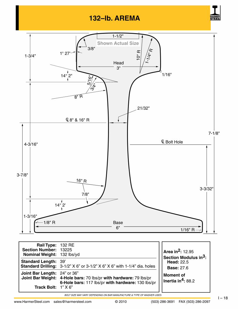
132–lb. AREMA
Area in2: 12.95Section Modulus in3: Head: 22.5 Base: 27.6
Moment ofInertia in4: 88.2
BOLT size MAY VARY DePeNDiNG ON BAR MANUFACTURe & TYPe OF WAsHeR UseD.
Head3"
Base6"
7-1/8"
4-3/16"
3-3/32"
1-1/
4" R
3-7/8"
1-3/4"
3/4"
5/16
"
3/8"
1/16"
1/16" R
1/8" R
21/32"
1-3/16"
8" R
10"
R
8" & 16" R
14° 2'
14° 2"
1° 27'
7/8"
16" R
1-1/2"
Bolt Hole
Shown Actual Size
Rail Type: 132 RE Section number: 13225 nominal Weight: 132 lbs/yd
Standard Length: 39’ Standard drilling: 3-1/2” X 6” or 3-1/2” X 6” X 6” with 1-1/4” dia. holes
Joint Bar Length: 24” or 36” Joint Bar Weight: 4-Hole bars: 70 lbs/pr with hardware: 79 lbs/pr 6-Hole bars: 117 lbs/pr with hardware: 130 lbs/pr Track Bolt: 1” X 6”

I – 19(503) 286-3691 FAX (503) 286-2097 © 2010 www.HarmerSteel.com [email protected]
133–lb. AREMA
Area in2: 13.10Section Modulus in3: Head: 22.3 Base: 26.9
Moment ofInertia in4: 86.3
BOLT size MAY VARY DePeNDiNG ON BAR MANUFACTURe & TYPe OF WAsHeR UseD.
Head3"
Base6"
7-1/16"
3-15/16"
3 "
1-1/
4" R
3-3/4"
1-15/16"
3/4"
7/16"
3/8"
1/16"
1/16" R
1/8" R
11/16"
1-3/16"
8" R
10"
R
16" & 8" R
18° 26' 10"
14°
4°
3/4"
16" R
1-13/32"
Bolt Hole
Shown Actual Size
Rail Type: 133 RE Section number: 13325 nominal Weight: 133 lbs/yd
Standard Length: 39’ Standard drilling: 3-1/2” X 6” X 6” with 1-1/4” dia. holes
Joint Bar Length: 38” Joint Bar Weight: 117 lbs/pr with hardware: 130 lbs/pr Track Bolt: 1” X 6”

I – 20www.HarmerSteel.com [email protected] © 2010 (503) 286-3691 FAX (503) 286-2097
136–lb. AREMA
Area in2: 13.32
Section Modulus in3: Head: 23.78
Base: 28.3
Moment of
Inertia in4: 93.7
BOLT size MAY VARY DePeNDiNG ON BAR MANUFACTURe & TYPe OF WAsHeR UseD.
Head2-15/16"
Base6"
7-5/16"
4-3/16"
3-3/32"
1-1/
4" R
3-7/8"
1-15/16"
3/4"
5/16"
9/16"
5/16"
1/16" R
1/8" R
11/16"
1-3/16"
8" R
10"
R
20" & 8" R
14° 2"
14° 2"
3/4"
20" R
Shown Actual Size
1-1/4"
Bolt Hole
Rail Type: 136 RE Section number: 13625 nominal Weight: 136 lbs/yd
Standard Length: 39’, 80’ Standard drilling: 3-1/2” X 6” or 3-1/2” X 6” X 6” with 1-1/4” dia. holes
Joint Bar Length: 24” or 36” Joint Bar Weight: 4-Hole bars: 70 lbs/pr with hardware: 79 lbs/pr 6-Hole bars: 117 lbs/pr with hardware: 130 lbs/pr Track Bolt: 1” X 6”

I – 21(503) 286-3691 FAX (503) 286-2097 © 2010 www.HarmerSteel.com [email protected]
Area in2: 13.80
Section Modulus in3: Head: 25.24
Base: 28.97
Moment of
Inertia in4: 100.44
BOLT size MAY VARY DePeNDiNG ON BAR MANUFACTURe & TYPe OF WAsHeR UseD.
141–lb. AREMA
Rail Type: 141 RE Section number: 14128 nominal Weight: 141 lbs/yd
Standard Length: 39’, 80’ Standard drilling: 3-1/2” X 6” or 3-1/2” X 6” X 6” with 1-1/4” dia. holes
Joint Bar Length: 24” or 36” Joint Bar Weight: 4-Hole bars: 70 lbs/pr with hardware: 79 lbs/pr 6-Hole bars: 117 lbs/pr with hardware: 130 lbs/pr Track Bolt: 1” X 6”
Head3-1/16"
Base6"
7-7/16"
4-3/32"
3-3/32"
1-3/
4" R
3-7/8"
2-5/32"
3/4"
5/16"
9/16"
5/16"
1/16" R
1/8" R
11/16"
1-3/16"
8" R
8"
R8" & 20" R
14° 2"
5°
18° 26' 10"
3/4"
20" R
1-13/128"
Bolt Hole
Shown Actual Size

II – 1www.HarmerSteel.com [email protected] © 2010 (503) 286-3691 FAX (503) 286-2097
AMERICAN CRANE RAILS
This section covers carbon steel crane rails of special designs and nominal weights of 104, 105, 135, 171, and 175 lbs. per yard for crane runway use. All of these rail sections are manufactured to ASTM A-759 specifications. Standard Control Cooled crane rails have a Brinell hardness of 250 to 280. As a supplement to the normal manufacturing process, crane rails can be head-hardened to a hardness of 321 to 388 Brinell. Crane rails are usually stocked in standard 39' lengths and are pre-drilled fortight-fit joint bars (see below). However, they are also available in 60' or 78' lengths and can be supplied with “blank ends” (no splice bar holes) for welding.
The standard drilling on the five crane rail sections is 4" X 5" x 6" with hole diameter and elevation as shown in the table below. The joint bars are punched on corresponding centers, except for the spacing between the two middle holes. The actual distance between these two holes is 7-15/16", or 1/16" less than the accumulated length (8") of the two rail ends to be covered by this portion of the joint bar. This allows the rail ends to be held firmly together, resulting in a “tight joint.” Because of cumulative tolerance variations in holes, bolt diameters, and rail ends, a slight gap may sometimes occur in the so-called tight joints. Conversely, it may sometimes be necessary to ream holes through joint bar and rail to permit entry of bolts.
Crane Spacing Hole Elev. Rail Inches Dia. Inches Section A B C D E 104 lb. 4 5 6 1-1/16 2-7/16
105 lb. 4 5 6 15/16 2-13/64
135 lb. 4 5 6 1-3/16 2-15/32
171 lb. 4 5 6 1-3/16 2-5/8
175 lb. 4 5 6 1-3/16 2-21/32
C B A
E
D
6" 5" 7-15/16" 5" 6" 2-1/32"2-1/32"
34"Base of Rail

II – 2(503) 286-3691 FAX (503) 286-2097 © 2010 www.HarmerSteel.com [email protected]
104–lb. CRANE RAIL
Rail Type: 104 CR Nominal Weight: 104 lbs/yd
Standard Length: 39' Standard Drilling: 4" X 5" X 6" with 1-1/16" dia. holes
Splice Bar Length: 34" Splice Bar Weight: 52 lbs/pr with hardware: 64 lbs/pr A325 Hex Bolt: 1" X 5-1/2"
Area in2: 10.287Section Modulus in3: Head: 10.691 Base: 13.512
Moment ofInertia in4: 29.843
toe of angle bar can be cut off (forming a splice bar) if desired
Head2-1/2"
Base 5"
Shown Actual Size
5"2-7/16"
2-7/16"
1-1/2"
1"
7/16"
1/16"
1/16" R
1/16" R
7/16"
1-1/16"
3-7/16" R Bolt Hole
13°
13°
5/16" R
12" R
2-7/16"

II – 3www.HarmerSteel.com [email protected] © 2010 (503) 286-3691 FAX (503) 286-2097
105–lb. CRANE RAIL
Rail Type: 105 CR Nominal Weight: 105 lbs/yd
Standard Length: 39' Standard Drilling: 4" X 5" X 6" with 15/16" dia. holes
Splice Bar Length: 34" Splice Bar Weight: 52 lbs/pr with hardware: 61 lbs/pr A325 Hex Bolt: 7/8" X 5"
Area in2: 10.3Section Modulus in3: Head: 12.39 Base: 14.28
Moment ofInertia in4: 34.41
Head2-9/16"
Base5-3/16"
Shown Actual Size
5-3/16"
12" R
2-13/32"
2-13/64"2-13/64"
1-25/32"
15/16"
1/4"
1/16"
1/ 16"R1/16" R
1/4"
1"
12" R Bolt Hole
13°
13°
5/16"

II – 4(503) 286-3691 FAX (503) 286-2097 © 2010 www.HarmerSteel.com [email protected]
135–lb. CRANE RAIL
Rail Type: 135 CR Nominal Weight: 135 lbs/yd
Standard Length: 39' Standard Drilling: 4" X 5" X 6" with 1-3/16" dia. holes
Splice Bar Length: 34" Splice Bar Weight: 62 lbs/pr with hardware: 78 lbs/pr A325 Hex Bolt: 1-1/8" X 5-1/2"
Area in2: 13.32Section Modulus in3: Head: 17.2 Base: 18.02
Moment ofInertia in4: 50.59
Head3-7/16"
Base5-3/16"
Shown Actual Size
5-3/4"2-13/16"
2-15/32"2-15/32"
1-7/8"
1-1/4"
3/4"
1/8" R
1/16" R
1/8" R
3/4"
1-1/16"
12" R Bolt Hole
13°
13°
7/16" R
14" R
3"

II – 5www.HarmerSteel.com [email protected] © 2010 (503) 286-3691 FAX (503) 286-2097
171–lb. CRANE RAIL
Rail Type: 171 CR Nominal Weight: 171 lbs/yd
Standard Length: 39' Standard Drilling: 4" X 5" X 6" with 1-3/16" dia. holes
Splice Bar Length: 34" Splice Bar Weight: 62 lbs/pr with hardware: 78 lbs/pr A325 Hex Bolt: 1-1/8" X 6-1/2"
Area in2: 16.811Section Modulus in3: Head: 24.51 Base: 24.42
Moment ofInertia in4: 73.398
Head4.3"
Base6"
Shown Actual Size
6"2-3/4"
2-5/8"2-5/8"
2"
1-1/4"
7/8"
1/4" R
1/ 16"R
1/ 2"R
3/4"
1-1/4"
12" R Bolt Hole
12°
12°
1/4" R to Approx. 3/8" R 4"

II – 6(503) 286-3691 FAX (503) 286-2097 © 2010 www.HarmerSteel.com [email protected]
175–lb. CRANE RAIL
Rail Type: 175 CR Nominal Weight: 175 lbs/yd
Standard Length: 39' Standard Drilling: 4" X 5" X 6" with 1-3/16" dia. holes
Splice Bar Length: 34" Splice Bar Weight: 72 lbs/pr with hardware: 89 lbs/pr A325 Hex Bolt: 1-1/8" X 6-1/2"
Area in2: 17.12Section Modulus in3: Head: 23.53 Base: 23.28
Moment ofInertia in4: 70.22
Head4-1/4"
18" R
Base6"
Shown Actual Size
6"3-7/64"
2-21/32"2-21/32"
1-3/4"
11/64"
1-1/2"
2"
1/4" R
1/16" R
5/16" R
1-1/8"
1-9/64"
Bolt Hole
12°
10°
12°
7/16" R 4-1/32" Approx.

II – 7www.HarmerSteel.com [email protected] © 2010 (503) 286-3691 FAX (503) 286-2097
Head Base
kg/m lbs/yd mm inch mm inch mm inch mm inch cm2 cm4 cm3 cm3
A45 22.10 44.55 45.00 1.77 55.00 2.17 125.00 4.92 24.00 0.94 28.20 90.00 41.50 27.00
A55 31.80 64.11 55.00 2.17 65.00 2.56 150.00 5.91 31.00 1.22 40.50 178.00 68.80 45.60
A65 43.10 86.88 65.00 2.56 75.00 2.95 175.00 6.89 38.00 1.50 54.90 319.00 105.40 71.30
A75 56.20 113.29 75.00 2.95 85.00 3.35 200.00 7.87 45.00 1.77 71.60 531.00 153.60 105.30
A100 74.30 149.78 100.00 3.94 95.00 3.74 200.00 7.87 60.00 2.36 94.70 856.00 203.40 161.80
A120 100.00 201.59 120.00 4.72 105.00 4.13 220.00 8.66 72.00 2.83 127.40 1361.00 289.10 235.00
A150 150.30 302.99 150.00 5.91 150.00 5.91 220.00 8.66 80.00 3.15 191.40 4373.00 601.50 565.70
EUROPEAN CRANE RAIL
Tensile Strength: S700 Grade 690 N/mm2 202 BHN S900A Grade 880 N/mm2 261 BHN S1100 Grade 1080 N/mm2 320 BHN
Standard Lengths: 10 Meters 12 Meters (most common) 15 Meters
Rails are supplied with blank ends (no holes). All joints must be welded.
Section
Weight Head Height Base Web AreaMoment
ofInertia
SectionModulus
Height
Head
Base
Web
European Crane Rails have a very wide base, low center of gravity and thick web. This makes them ideal for supporting strong lateral forces. They are available in various section profiles from A45 to A150. The number refers to the width of the head in millimeters. Thus an A150 crane rail has a head width of 150 millimeters. These crane rails are manufactured in accordance with European technical specification DIN 536 and are available in three grades. The standard grade, S700, is the one most commonly ordered, but two higher grades are also available. See table below for minimum tensile strength for each grade. The strength and hardness of the S1100 grade is achieved by using a chrome-vanadium alloy steel.

II – 8(503) 286-3691 FAX (503) 286-2097 © 2010 www.HarmerSteel.com [email protected]
WEIGHT AND MEASURE CONVERSION TABLE
Weight
1 Net Ton (NT) = 2,000 lbs.1 Gross Ton (GT) = 2,240 lbs.1 Metric Ton (MT) = 2,204.6 lbs.1 Metric Ton = 1,000 kilograms1 Kilogram = 2.2046 lbs.1 Pound = 0.4536 kilograms
Board Foot Calculator
1 Board Foot = a piece of wood that is 1" thick and 1' long and 1' wide.
Board Feet of railroad ties can be calculated as follows: (H x D x L)/12 where H and D are the height and depth in inches and L is the length in feet. Board Measure for 7" x 9" ties is as follows:
7" x 9" x 8'6" = 44.625 bf 7" x 9" x 13' = 68.25 bf 7" x 9" x 9' = 47.25 bf 7" x 9" x 14' = 73.50 bf 7" x 9" x 10' = 52.50 bf 7" x 9" x 15' = 78.75 bf 7" x 9" x 11' = 57.75 bf 7" x 9" x 16' = 84.00 bf 7" x 9" x 12' = 63.00 bf 7" x 9" x 17' = 89.25 bf
Linear Measure
1 mil = 0.001 inch 1 inch = 1000 mils 12 inches = 1 foot 3 feet = 1 yard5,280 feet = 1 mile1,760 yards = 1 mile
Metric and English Conversion TableLinear Measure
1 kilometer = 0.6214 mile 1 mile = 1.609 kilometer1 meter = 39.37 inches 1 yard = 0.9144 meter1 meter = 3.2808 feet 1 foot = 0.3048 meter1 meter = 1.0936 yard 1 foot = 304.8 millimeters1 centimeter = 0.3937 inch 1 inch = 2.54 centimeters1 millimeter = 0.03937 inch 1 inch = 25.4 millimeters

III – 1www.HarmerSteel.com [email protected] © 2010 (503) 286-3691 FAX (503) 286-2097
HOOK BOLTS
Hook bolts are very commonly used to attach lighter rails (usually up to 85 lbs.) to channels (as shown at left) or directly onto a crane rail beam. They are usually threaded to allow up to one half inch lateral adjustment in either direction, and come complete with hex nuts and lockwashers. When ordering, specify rail section, bolt diameter, and the size and weight of supporting beam or channel.
Hook bolts are typically drilled in pairs four inches apart every two feet. Unless otherwise specified, we drill these holes 1/8 inch larger than the diameter of the hook bolt, and the spacing will be as shown in the table below. Typically the hook bolts are the same diameter as that used for the splice bars. (Hole elevation is the same as for splice bar holes.)
Remaining holeson 24" centers
AB B
DD
CC
EE
*See pages I-5 thru I-12 for rail end drilling.
Hook Bolt Spacing *
Rail Weight A B C D E No. holes per rail
12 lb to 60 lb 20' 14" 22" 12" 4" 20
12 lb to 60 lb 30' 14" 22" 12" 4" 30
25 lb to 60 lb 40' 14" 22" 12" 4" 40
60 lb to 80 lb 33' 18" 24" 16" 4" 32
80 lb to 85 lb 39' 18" 24" 16" 4" 38
III – 2(503) 286-3691 FAX (503) 286-2097 © 2010 www.HarmerSteel.com [email protected]
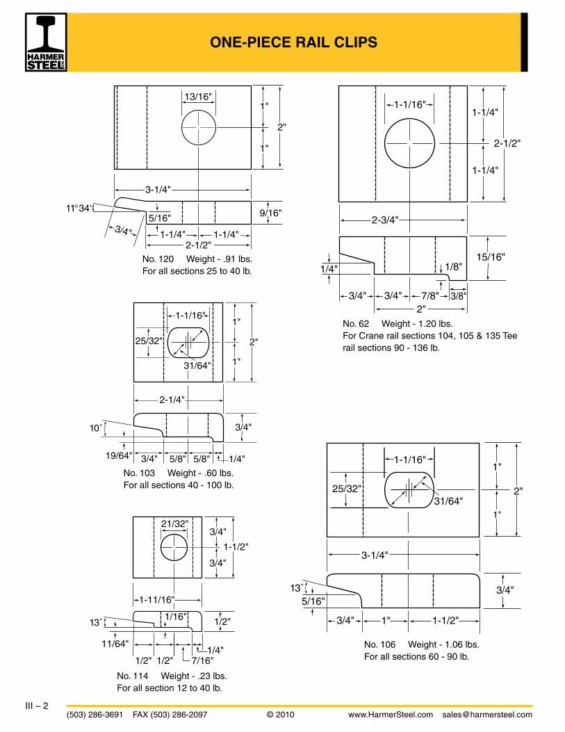
ONE-PIECE RAIL CLIPS
No. 106 Weight - 1.06 lbs.For all sections 60 - 90 lb.
No. 120 Weight - .91 lbs.For all sections 25 to 40 lb.
No. 114 Weight - .23 lbs.For all section 12 to 40 lb.
No. 103 Weight - .60 lbs.For all sections 40 - 100 lb.
No. 62 Weight - 1.20 lbs.For Crane rail sections 104, 105 & 135 Tee rail sections 90 - 136 lb.
1-1/16"1-1/4"
1-1/4"
2-1/2"
15/16"
2-3/4"
3/4" 3/4" 3/8"7/8"
1/4"
2"
1/8"
3-1/4"
1"
2"
1"
13/16"
1-1/4" 1-1/4"3/4"
9/16"
2-1/2"
5/16"11°34'
1"
2"
1"
25/32"
1-1/16"
2-1/4"
3/4"
3/4" 1/4"5/8"5/8"19/64"
10˚
31/64"
3/4"
3/4"21/32"
1/2"
1/2" 1/2" 7/16"1/4"
1-11/16"
1-1/2"
11/64"
13˚1/16"
1"
2"
1"
1"
3/4"
3/4"
1-1/2"
3-1/4"
25/32"
1-1/16"
5/16"13˚
31/64"

III – 3www.HarmerSteel.com [email protected] © 2010 (503) 286-3691 FAX (503) 286-2097
ONE-PIECE RAIL CLIPS, CRANE STOPS
Crane Stops
This Heavy-Duty Crane Stop is for use on all rail sizes (up to and including 175-lb.) and especially where large cranes are operating. It is fabricated to necessary height and contour to correspond with the wheel diameter of the crane. Specify rail size and wheel diameter when ordering.
Several other types of crane stops are also available. Lighter duty stops, and stops designed to contact a bumper mounted on the crane are two varieties commonly requested.
No. 171 Weight - 3.60 lbs.For 171 lb. Crane rail.
No. 175 Weight - 2.19 lbs.For 175 lb. Crane rail.
Cushion-Slide Crane Stops
Drag plates allow wedge to slide some distance to absorb impact. On smaller sizes of rail, plates may interfere with rail hook bolts. Allow sufficient sliding distance between cranes. Stopping distance depends on weight and speed of crane. Do not use at end of crane run.
Wheel Contact TypeWedges are made for a specific wheel diameter. Plates are cut to fit a specific rail size and section.
Bumper Contact TypeFits most standard crane bumpers. Wedge stands 15" above top of rail. Underside of crane bumpers should be no more that 12" above top of rail. Plates are cut to fit a specific rail size and section.
1-1/16"1-1/4"
1-1/4"
2-1/2"
4-1/2"
1-1/2" 2-1/4"3/4"
3/4"1-1/2"
1/8"
1/8"5/16"R
2-1/2" 2"
1"
3-1/2"
1-1/8" 1-1/8"7/8" 3/8"
1-3/8"
1-3/8"
2-3/4"
1-1/16"
5/16"R
5/16"
1/8"

III – 4(503) 286-3691 FAX (503) 286-2097 © 2010 www.HarmerSteel.com [email protected]
SOFT-MOUNT CRANE RAIL SYSTEMS
IntroductionThe ever growing demands by industry for increased automation and higher plant output rates resulted in the development of generation after generation of higher speed, heavier duty modern bridge cranes. While mechanical engineers concentrated their efforts on designing bigger and more efficient cranes, structural engineers maintained an equivalent pace in improving crane girder, support structure and foundation designs. Between these two fields of expertise lies the crane rail, which represents the hinge point of the installation. Traditional rail mounting methods have, in general, not kept pace with the ever increasing demands made on them.
The result can be that this relatively inexpensive area, in terms of initial outlay and design, can cause considerable operating expenses that manifest themselves in the short term by high wear rates in wheels, bearings, axles and rail breakage, with the associated down time, maintenance cost and high noise levels.
In the longer term, the impact and vibration transmitted to the girder structure and foundations can result in structural damage and possible girder failure due to excessive fatigue stressing.
FatigueThe area of contact between a steel rail and the top flange of a crane girder can be as little as one percent of the projected area of the rail. Since both the rail and girder are stiff in compression, even heavy wheel loads will not substantially increase the contact area, and very large local stresses result. To compound this problem, these contact points are randomly distributed, leading to complex and indeterminate stress patterns in the supporting girder. Continuous movement and shock loads produced by the operations of the crane can and usually do result in fatigue and consequent damage to both the crane rail and the girder. The most common manifestation is cracking in the upper portion of the web.
Where rails are mounted on concrete, a similar rationale applies with resulting progressive disintegration of the concrete and loosening of the anchor bolts.
Crane Rail MountingSoft mounting crane rail systems have developed over 35 years in an effort to reduce the all too frequent problems associated with crane rail installations. Today’s line of mounting pads and clips are sophisticated, proven and easy to install. They result in reduced mechanical wear, lower impact due to shock loading, less vibration and a quieter installation. These systems consist of steel reinforced, vulcanized, synthetic rubber pads and resilient clips designed specifically for the mounting of crane rails in light, medium or heavy duty applications.
Pads protect the installation by:• Distributing and recentering the load• Eliminating point contact• Reducing impact, vibration and noise• Absorbing relative motion between rail and girder• Eliminating fretting of the top girder flange
Clips complement the pad by:• Ensuring continuous and permanent contact between the rail, pad, and girder at all times• Constraining the rail in the vertical and lateral planes while allowing controlled movement in
the axial direction• Allowing lateral adjustment during and after installation• Performing consistently over many years without maintenance, loosening of the anchor bolts,
or fatigue failure

III – 5www.HarmerSteel.com [email protected] © 2010 (503) 286-3691 FAX (503) 286-2097
SOFT-MOUNT CRANE RAIL SYSTEM CLIPS
Soft-mount clips are specifically designed for the mounting of crane rails, with or without pad. Clips consist of two interacting components which allow easy lateral rail adjustment and, once correctly installed, are self-locking and self-tightening. A controlled vertical force is applied to the rail base through a synthetic rubber “nose,” which is vulcanized bonded to the appropriate clip component.
Technical Advantages of Soft–Mount Rail Clips • Simple and positive lateral rail adjustment up to 3/4" (20mm), depending on type of clips • Very high resistance to lateral loads through careful selection of clip component materials • Controlled vertical force applied to rail and girder tolerances • Accommodates rail and girder tolerances • Eliminates fatigue effects on bolt (or stud) • Minimizes crane runway maintenance and down time • Ensures contact between rail and pad under the rail • Controls axial movement of broken rail • Eliminates loosening of bolts • Reduces noise and vibration
Weldable Crane Rail ClipsTechnical Advantages of Weldable Rail Clips: • Simple and positive lateral rail adjustment up to 3/4" (20mm), depending on type of clips • Self-locking and self-tightening features through system of double wedging action
Boltable (or Stud Mount) Crane Rail Clips
Technical Advantages of Boltable (or Stud Mount) Rail Clips: • Simple and positive lateral rail adjustment up to 3/4" (20mm), depending on type of clips • Cam adjustment is self-locking • The true cam design ensures that the force is transmitted to the fastener (bolt or stud) in the most efficient means possible and is completely independent of friction.

III – 6(503) 286-3691 FAX (503) 286-2097 © 2010 www.HarmerSteel.com [email protected]
CRANE RAIL PADS, GIRDER TIE-BACK LINKAGES
Heavy Duty Rail Applications
The heavy duty pad has been specifically designed for the soft mounting of crane rails. It is manufactured from a synthetic elastomer especially resistant to wear, shear and crushing as well as oil, grease, ozone, and ultraviolet rays. Its upper face is grooved in order to obtain a variable stiffness. This increases the pad’s resistance to wear without introducing excessive bending in the rail. It is reinforced with a high strength steel strip and fully vulcanized to the rubber. The reinforcement acts as a diaphragm and gives the pad lateral stiffness, preventing it from deflecting under the side thrust of the rail, regardless of wheel load and loss of friction from oil or grease. Edge seals on both the top and bottom surfaces prevent the ingress of dirt and water which can cause premature failure of the pad, rail and support structure.
Features include: • Distribute the wheel load over a larger surface area • Eliminate load concentration and the resulting fatigue stresses • Compensate for the uneven surface between the rail and its support • Reduce impact, vibration, and noise • Eliminate fretting corrosion (wear) of the support surface under the rail
The discontinuous rail pad is specifically developed to overcome the problems associated with discontinuous rail support. The pad is available to suit all rails and is designed to be used on a steel soleplate with shim packs or grout.
• Crowned construction centers load on pedestal and eliminate edge load on concrete pedestals
• Molded end-stops prevent longitudinal creep• Elastomer construction reduces shock and vibration, noise,
and local bearing stress on concrete Discontinuous Rail Support
A common area of failure with active crane runways is the crane girder to building column connection.The Tie-Back System is designed to provide a proven solution to this problem. Some of the most important characteristics are:
• Spherical bearings allow girder end rotation, longitudinal and vertical movement without stressing the tieback linkage.
• A single linkage can transmit up to a 165 kip side thrust in tension or compression.
• Sizes are available to fit any girder and column configuration.• The tie-back linkage assembly eliminates diaphragms and the
associated maintenance from cracking.• Designed to suit any application.
Girder Tie-Back Linkage

III – 7www.HarmerSteel.com [email protected] © 2010 (503) 286-3691 FAX (503) 286-2097
APPLICATION DATA SHEET
Company _________________________Contact _______________________Phone ___________
Address ________________________________________________________Fax _____________
Project Name ________________________________________ Email _______________________
Please supply the information requested below:
Soft-Mount Crane Rail Fastening System
Type of Industry & Application ____________________________________________________ ❏ New runway ❏ Existing runway Existing fastening system ________________
Runway: ❏ Inside ❏ Outside Length ________________ ❏ Concrete Supported ❏ Overhead Girder Width of Girder or Support _______ ❏ Continous Support ❏ Discontinous Support
Environment: ❏ Damp ❏ Corrosive ❏ Excess of oil, grease ❏ Marine ❏ Acid Vapors ❏ Other ________________________
Ambient temperature range ____________________________________
Design of Structure: If possible, please supply crane runway structural or concrete beam drawing.
Crane: Crane capacity ________________________Crane span __________________
Number of cranes per track ______________ Gantry speed _________________
Maximum lift _________________________ Total weight of crane ___________
Wheel drive design _________________________________________________
Number of wheels per corner ____________ Wheel diameter _______________
Wheel center distance __________________ See drawing No. ______________
Wheel tread: ❏ Tapered ❏ Flat
Maximum vertical wheel load ________ Static _________ Dynamic __________
Maximum side thrust per wheel _______________________________________
Wheel guidance method: ❏ Flanged wheel ❏ Side rollers
(Provide dimensional drawings for clip clearance verification)
Rail: Size and profile ____________________________________________________
Rail Joint: ❏ Bolted ❏ Welded
Expansion joint: ❏ Yes ❏ No ❏ Quantity ___________
Preferred attachment system: ❏ Weldable clip ❏ Boltable clips
❏ with Rail pad ❏ without Rail pad
Clip spacing _______________________________________________________
Comments: ________________________________________________________________
________________________________________________________________
________________________________________________________________
________________________________________________________________

III – 8(503) 286-3691 FAX (503) 286-2097 © 2010 www.HarmerSteel.com [email protected]
RAIL CLAMPS FOR CRANE RAILS
Clamp and Reversible Filler, Tight Fit
No. 203 – Single
No. 204 – Double
NOTE: Clearances L (left) and R (right) can be varied by reversing the filler.
2-1/2"
6"
6"
3"
1-1/2"
1-5/32"
1-1/16" Holesfor 1" bolts
1-1/2"
3"
1-1/2"
1-1/2"
2-1/2"
1-1/4"
1-1/16"1-11/32"
Reversible filler
1-1/16" Holesfor 1" bolts
Double clip
Base
Gage
Single clips and fillersare half length
T
L R
1/4" 1/2"
Rail Base Gage CL to CL Filler Est. Wt. Clamp Est. Wt. Filler Sec. Width Holes Thickness (T) Single Double Single Double
104-CR 5" 7-3/4" 1/2" 1.6 lb 3.2 lb 1.05 lb 2.1 lb
105-CR 5-3/16" 8" 3/8" 1.6 lb 3.2 lb .72 lb 1.44 lb
135-CR 5-3/16" 8" 1/2" 1.6 lb 3.2 lb 1.05 lb 2.1 lb
171-CR 6" 8-3/4" 5/8" 1.6 lb 3.2 lb 1.3 lb 2.6 lb
175-CR 6" 8-3/4" 1/2" 1.6 lb 3.2 lb 1.05 lb 2.1 lb

III – 9www.HarmerSteel.com [email protected] © 2010 (503) 286-3691 FAX (503) 286-2097
RAIL CLAMPS FOR CRANE RAILS
Clamp and Reversible Filler, Loose Fit (“Floating”)
No. 205 – Single
No. 206 – Double
2-1/2"
6"
6"
3"
1-1/2"
1-5/32"
1-1/16" Holesfor 1" bolts
1-1/2"
3"
1-1/2"
1-1/2"
2-1/2"
1/2"1-1/4"
1-1/16"1-11/32"
Reversible filler
1-1/16" Holesfor 1" bolts
Double clip
Bend in 1-1/4"
Base
Gage
Single clips and fillersare half length
T
L R
1/4"
NOTE: Clearances L (left) and R (right) can be varied by reversing the filler.
Rail Base Gage CL to CL Filler Est. Wt. Clamp Est. Wt. Filler Sec. Width Holes Thickness (T) Single Double Single Double
104-CR 5" 7-3/4" 5/8" 1.6 lb 3.2 lb 1.3 lb 2.6 lb
105-CR 5-3/16" 8" 1/2" 1.6 lb 3.2 lb 1.05 lb 2.1 lb
135-CR 5-3/16" 8" 5/8" 1.6 lb 3.2 lb 1.3 lb 2.6 lb
171-CR 6" 8-3/4" 3/4" 1.6 lb 3.2 lb 1.6 lb 3.2 lb
175-CR 6" 8-3/4" 5/8" 1.6 lb 3.2 lb 1.3 lb 2.6 lb
III – 10(503) 286-3691 FAX (503) 286-2097 © 2010 www.HarmerSteel.com [email protected]
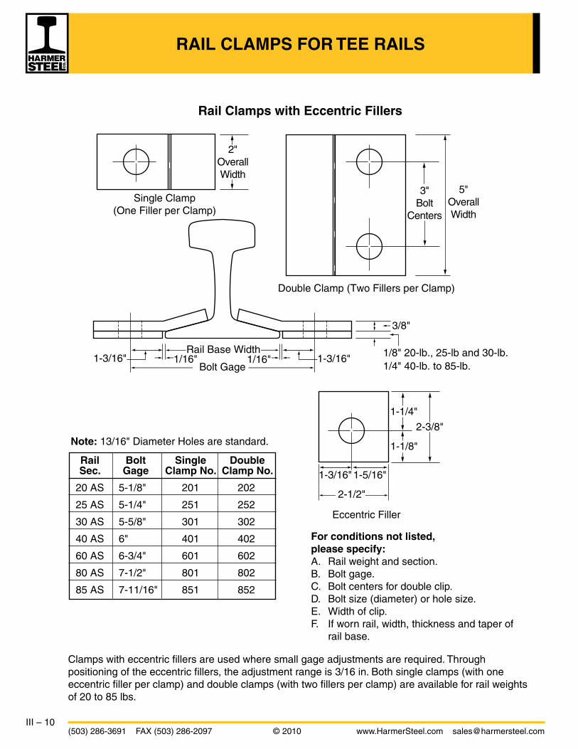
RAIL CLAMPS FOR TEE RAILS
Clamps with eccentric fillers are used where small gage adjustments are required. Through positioning of the eccentric fillers, the adjustment range is 3/16 in. Both single clamps (with one eccentric filler per clamp) and double clamps (with two fillers per clamp) are available for rail weights of 20 to 85 lbs.
Rail Clamps with Eccentric Fillers
For conditions not listed,please specify:A. Rail weight and section.B. Bolt gage.C. Bolt centers for double clip.D. Bolt size (diameter) or hole size.E. Width of clip.F. If worn rail, width, thickness and taper of
rail base.
1-3/16"
2-1/2"
1-5/16"
2"OverallWidth
3"Bolt
Centers
5"OverallWidth
Rail Base Width
Bolt Gage
Double Clamp (Two Fillers per Clamp)
Eccentric Filler
Single Clamp(One Filler per Clamp)
1/8" 20-lb., 25-lb and 30-lb.1/4" 40-lb. to 85-lb.
1/16" 1/16" 1-3/16"
3/8"
1-1/8"
1-1/4"
2-3/8"
1-3/16"
Note: 13/16" Diameter Holes are standard.
Rail Bolt Single Double Sec. Gage Clamp No. Clamp No.
20 AS 5-1/8" 201 202
25 AS 5-1/4" 251 252
30 AS 5-5/8" 301 302
40 AS 6" 401 402
60 AS 6-3/4" 601 602
80 AS 7-1/2" 801 802
85 AS 7-11/16" 851 852

IV – 1www.HarmerSteel.com [email protected] © 2010 (503) 286-3691 FAX (503) 286-2097
Gage Rods are designed for installation at weak points in track, sharp curves, switches, bad ties, temporary track, areas with poor ballast, etc. The rods hold tracks to gage by preventing spreading of rails. They will reduce the need to respike the track and will prevent tilting of rails. The standard rods are made of 1-1/4” diameter rod to fit all tee rail sections 70-lb. and above on a standard56-1/2” gage.
Non-Insulated
Single End Gage Rods have a hook on one end, and a single jaw with nut and spring lock washer on the other end.
Double End Gage Rods have two jaws, two nuts, and two washers on both ends of the rod.
Insulated
Insulated Gage Rods are available for track with signals or anywhere that electrical insulation is required. The most common style is shown below and features an insulation material in the center of the rod. Both single and double end insulated rods are available.
GAGE RODS
Single End – Weight 28 lbs
Double End – Weight 37 lbs
Single End – Weight 29 lbs
Double End – Weight 38 lbs

IV – 2(503) 286-3691 FAX (503) 286-2097 © 2010 www.HarmerSteel.com [email protected]
Diamond neck track bolts are stocked in the sizes shown below.
Hex head bolts are usually supplied to ASTM A-325 specifications and are mainly used for crane rail joint bars with tight joints.
Square head bolts are used for heel blocks and the toe end of self-guarded frogs, and can be supplied with cotter pins for use in switch rods. They are manufactured to SAE Grade 5 specifications.
BOLTS, WASHERS
Track Bolts
Diam. Length Avg. no.
“D” “L” in 200# can
inches inches pieces
1/2 1-3/4 925 1/2 2 885 1/2 2-1/4 845 5/8 2-1/2 470 3/4 3 277 3/4 3-1/2 259 3/4 4 242 7/8 4-1/2 159 7/8 5 149 1 5 108 1 5-1/2 104 1 6 100 1-1/16 6 93 1-1/8 6-1/2 72
AREMA Plain Pattern
Button head oval neck track bolts are made with oval necks and button heads to be used for splice bar connections. The oval neck fits into the oval hole in the connector bar, thus allowing tightening of the nut without the use of a second wrench to keep the bolt from turning. These bolts are manufactured per ASTM A-183 specifications to both a heat-treated (Grade 2) and an untreated (Grade 1) designation.
Track bolts come with heavy square nuts, and are packed in cans containing 200 lbs. of bolts and nuts. The table at left shows the sizes normally stocked by Harmer. In addition, Harmer stocks longer length track bolts (for heel blocks and cast frogs), and can supply special size track bolts on request.
Railway spring washers are made from high grade steel and are designed to maintain bolt tension under all conditions. They are available in two primary designs.
45°
45°
A
B B
Avg. no.
Diam. Length in 100# can
inches inches pieces
7/8 4-1/2 80 7/8 5-1/2 70 1 5-1/4 50 1 5-3/4 50
V
A
r3
H L
PD
ORr1
r2

IV – 3www.HarmerSteel.com [email protected] © 2010 (503) 286-3691 FAX (503) 286-2097
SPIKES
Track spikes are manufactured to AREMA specifications in both soft steel and high carbon varieties. In addition, good quality industrial grade spikes are stocked in the larger spike sizes. Industrial grade spikes are not guaranteed to meet AREMA specifications and may exceed AREMA dimensional tolerances. Although they generally will not work in automatic spiking machines, they are very popular with customers who do not use these machines. Top quality second-hand 5/8” x 6” track spikes (hand-sorted into drums) are readily available and offer a substantial savings when compared to the cost of new track spikes.
Boat spikes are available both galvanized and “black.” Common sizes are 3/8” X 6”, 3/8” X 8”, 3/8” X 10”, 1/2” X 10”, and 1/2” X 12”.
Specialty screw spikes are available for a wide variety of installations for grade crossing, maintenance of way, and bridge timbers. The samples shown below represent a small part of the array that Harmer can provide.
Dimensions and Quantities
Size of spike Head Length Approxi- of taper mate of point number Thickness Length Length Width per keg of A B C D E 100 lb.
in. in. in. in. in.
3/8 3 1-1/16 7/8 5/8 635 3/8 3-1/2 1-1/16 7/8 5/8 568 1/2 4-1/2 1-5/16 1-1/8 7/8 253
9/16 5-1/2 1-1/2 1-1/4 1-1/8 161 5/8 5-1/2 1-9/16 1-5/16 1-1/4 132 5/8 6 1-9/16 1-5/16 1-1/4 121
Fig
. 2
Fig
. 1
Topview
Sideview
Screw Bevel head Dome head Washer Recessed Recessed spike drive spike drive spike head head head 4 notch drive spike square round
Smallspikes
Largespikes
Fig. 2AREMA
ReinforcedThroat
9/16” and5/8”
Fig. 1for3/8”and1/2”
D
C
D
CD D
A A A AB B
EE

IV – 4(503) 286-3691 FAX (503) 286-2097 © 2010 www.HarmerSteel.com [email protected]
Single Shoulder
RAIL ANCHORS, TIE PLATES
Improved Fair Unit V Channeloc
Rail anchors are manufactured in one-piece construction from spring steel or equal, heat-treated and designed to eliminate creepage of track. They provide a large bearing surface against both rail base and tie, avoiding undo cutting and wear, thus prolonging the life of wood ties. All anchors shown above are “drive-on” type anchors which are driven on using a standard spike maul.
The use of single or double shoulder tie plates makes a more stable track and greatly lengthens the life of wood ties. Punched and sheared from hot-rolled steel sections, tie plates provide proper cant, uniform bearing surface for the rail, and better load distribution to the ties. They hold the rail to gage, providing more uniform wear to rail head, and protect against undue wear to ties. Tie plates are designed with a long end or field end to be located outside of the rails. In the case of single shoulder tie plates, the shoulder is placed on the field end of the plate. The gage end or short end of the plate is located inside of the rails.
When ordering, identification of the rail section or the width of the rail base should be specified. Top quality relay tie plates (hand-sorted and palletized) are readily available and offer a substantial savings when compared to the cost of new tie plates. Tie plates come in a variety of sizes and punching patterns. These patterns may include both “line holes” and “hold-down holes.” The plates shown above have four line holes punched to line up with the edge of the rail base. Many tie plates also feature hold-down (or “anchor”) holes that are between the line holes and the edges of the tie plate.
Double Shoulder
*weight based on 8-hole 7-3/4” wide plate, except plan 1 and 2UP/CN 16” plate is 6-hole
Standard Plate Sizes
Rail AREMA SS Plate Plate Base Width Plan DS Weight* Length
4-7/16 to 5-1/8 1 SS 11.63 10 5-1/8 to 5-1/2 2 SS 12.93 11 5-3/8 3 DS 15.86 12 5-1/2 4 DS 13.45 11 5 DS 16.25 12 7 DS 19.60 13 8 DS 22.90 14 6 9 DS 14.94 12 10 DS 17.87 13 12 DS 21.47 14 13 DS 23.32 14-3/4 UP/CN DS 27.67 16

IV – 5www.HarmerSteel.com [email protected] © 2010 (503) 286-3691 FAX (503) 286-2097
DIRECT FIXATION TIE PLATES, STEEL TIES
Direct fixation tie plates utilize an elastic clip (“e-Clip”) design to secure the rail to the base plate. The spring and torsion work in unison to produce a high clamping force, aiding in preventing rail rollover and providing longitudinal restraint.
Plates are available for 5-1/2” and 6” rail base widths with a 1:40 cant. Standard punching includes four round holes and 2 square holes. Other designs may be available upon request.
Plates can be securely fastened to wooden ties by means of screw-spikes. Alternate design clips are available for use at track joints, where joint bars would obstruct the use of standard clips.
As an alternate to wooden ties, steel ties are available for traditional railroad applications. Utilizing a “hook-in shoulder” design, steel ties have superior gage and cant holding capabilities. Along with standard 56-1/2” gage, steel ties are available for switch installations as per AREMA or railroad specifications. Each set comes with prepunched labeled ties and all standard or speciality fasteners necessary to secure the points, rail, frog, guard rails, and switch machine to the ties. Steel track and turnout ties can be assembled efficiently even with an inexperienced crew. They can reduce the amount of ballast required up to 40% compared to other tie materials. Steel ties can also be used to extend the life of wooden ties when interspersed.
1:40 Cant
Length
Wid
th
Holding Gage
4 Ballast Inspection Holes
Front arch
Toe
Heel
Rear arch
Ctr.leg
e-Clip
Holes Punched toSuit Rail Weight
SectionViews
Rail Seat Area

IV – 6(503) 286-3691 FAX (503) 286-2097 © 2010 www.HarmerSteel.com [email protected]
STEEL MINE TIES
Steel ties have a decided advantage over wood ties in mining applications. They hold the rails securely, keeping them true to gage and the track in alignment. They have unusually long life, even under severe service conditions, and can never become spike-killed or rotted. Also, they are not a fire hazard.
The ties are light compared to wood. One man can easily handle a bundle of five ties. The ties are relatively shallow in section, thereby saving valuable head-room in low seams. The heavier ties are sometimes used for main-haulage tracks, and are often used in conjunction with wood ties in place of gage rods, by spacing them between every third or fourth tie. By adding a steel tie at 6’ to 10’ intervals, the service of wood ties will be prolonged through relief of strain during the early period of decay.
To provide even greater strength, steel ties can be supplied that are bolted to a wood base. The base is grooved (so that it will fit up under the tie) and bolted securely to the tie. Oak is usually used, and it can be treated or left untreated.
Installation of Steel Ties
The installation of steel ties with riveted clips is simple and easy. Whether the ties are straight or upset end, they are installed in the same manner. No gaging of track is required.
1. The rail is placed on the tie, in position against the stationary clip. 2. Blows of a hammer turn the
movable clips into position over the rail base.
3. The clips hold the rail firmly in place, to accurate gage.

IV – 7www.HarmerSteel.com [email protected] © 2010 (503) 286-3691 FAX (503) 286-2097
STEEL MINE TIES
Steel Ties with Outside Stationary Clips
In all sections the most widely used tie is the outside stationary clip tie. It is equipped with fourrolled-steel movable clips, and two stationary clips placed on the outside ends, as illustrated. The clips are spaced to fit one particular rail section.
Steel Ties with Staggered Clips
Also available is the staggered clip tie, which is equipped with four rolled-steel movable clips and two stationary clips, with a stationary clip on the inside at one end, and on the outside at the other end. This feature is especially useful when it is desired to insert or remove a tie without disturbing the track gage. The clips are spaced to fit one particular rail section.
Tunnel Ties
Tunnel Ties are specifically designed for use in tunneling projects where the bottom surface is not flat. These ties can be used without blocking and will maintain proper track gage. Each tie is designed specifically to meet the requirements for a particular job. Customers should specify the tunnel diameter, wheel load, and tie spacing. The design specifications are reviewed by an engineer to ensure tie construction will support the wheel loads required for a given project. Axle loads of 45,000 lbs on 30” tie spacing have been successfully implemented.

IV – 8(503) 286-3691 FAX (503) 286-2097 © 2010 www.HarmerSteel.com [email protected]
STEEL MINE TIES
Shown on this page are some of the most common steel tie sections available today. Although the table below gives some general recommendations, there are several factors to be considered in choosing a steel tie. These include condition of the bottom, weight of cars and equipment, amount and speed of traffic, permanency of trackage, and weight of rail.
5-1/4"
5/32" 1-3/32"
5-1/4"
11/64" 1-3/32"
5-11/32"
13/64" 1-1/8"
2"
1-3/4"5-7/8"
3/4"
T-4 T-6
T-9T-5
Drawings shown to scaleNot actual size
Tie Section Weight Rail Section
T – 4 3.85 lbs/ft 30 - 60 lb
T – 5 5.0 lbs/ft 30 - 60 lb
T – 6 6.0 lbs/ft 40 - 85 lb
T – 9 10.5 lbs/ft 60 - 100 lb

IV – 9www.HarmerSteel.com [email protected] © 2010 (503) 286-3691 FAX (503) 286-2097
Bill of Switch Ties for Turnouts with Straight Switches* Frog Length Toe Lead Lengths and Quantities of Ties Quant. Board No. of Switch Length to P.S. to (Lengths in 1'-0" Multiples) of Measure Rail 1/2" Pt. 1/2" Pt. 9' 10' 11' 12' 13' 14' 15' 16' 17' Ties
6 11'0" 3'9" 47'6" 4 9 5 5 3 3 5 5 2 41 2683
7 16'6" 4'8-1/2" 62'1" 7 13 6 5 3 4 6 6 2 52 3329
8 16'6" 5'1" 68'0" 7 13 6 6 4 5 7 6 3 57 3701
9 16'6" 6'4-1/2" 72'3-1/2" 7 13 7 7 6 5 8 6 4 63 4127
10 16'6" 6'5" 78'9" 7 15 8 7 6 6 7 8 4 68 4452
11 19'6" 7'0" 83'6" 9 14 9 8 7 6 8 8 4 73 4762
*No. 11 shown is for curved switch
WOOD TIES, TIE PLUGS
Tie plugs are for filling holes in new or used cross ties where spikes have been removed. The plugs are sold in bundles of 500, and are normally 5/8” square and 4-3/4” long. They are available in both treated and untreated cedar.
Weight 20 lbs/bndl. (treated) 18 lbs/bndl. (untreated)
We stock “headed” plugs as shown below.
Pressure treated cross ties for standard railroad gage are usually supplied in lengths of 8’ or 8’ 6”. They are cut with cross sections of either 6” X 8”, 7” X 8”, or 7” X 9”. Ties are available in several different species of wood, and hardwood ties are often furnished with end plates to reduce splitting. In addition to new ties, relay quality used ties are available.
The table below shows a bill of switch ties for standard gage turnouts with frog numbers between six and eleven. These quantities and lengths are per AREMA specifications with tie lengths rounded up to the nearest 1’ multiple. (The board measure shown is based on ties of a 7” x 9” cross section.) Ties are also available in sets with slightly wider spacing between ties, which is usually sufficient for industrial trackage.

IV – 10(503) 286-3691 FAX (503) 286-2097 © 2010 www.HarmerSteel.com [email protected]
COMPROMISE AND INSULATED JOINT BARS
Compromise Joint Bars are designed to join rail sections of different sizes while keeping gage and running surfaces in alignment. Compromise joints consist of two bars – an “outside joint bar” and a “gage side joint bar.” Generally speaking, unless the difference between the rail head widths is less than 3/16”, right and left-hand joints are required. Unless otherwise specified:1) bolt holes are alternately round and oval,2) bolts are not provided, and3) rail joint opening is 1/8”.
Insulated Joint BarsSteel bar core has exceptional strength, providing the fatigue resistance to withstand punishing loads and curve forces. Electrical integrity is derived from a high durable polyurethane coating that resists moisture and excessive temperature. Insulated rail joints are furnished with steel-lined bushings and insulated high-pressure end post.
• Strongheat-treatedsteelcoreprovidesfullsupportforrailends
• Polyurethaneinsulationcompletelysurroundsthecore- including the bolt bole - providing superior insulating properties
• Resistanttomoisture,abrasion,cracking,grease,oil,brine,weather and insects
• Unaffectedbytemperatureextremes
• Conformstorailirregularities
Stand between “Heavy” rails, facing direction of the “Light” rails. Indicate the joint to the right as “Right Hand” joint, and the joint to the left as the “Left Hand” joint.
To Determine Right-Hand or Left-Hand Joint To DetermineBolt Hole Locations
Gage side joint bar (4L)
Gage side joint bar (2R)
Outside joint bar (1R)
Joint length – Overall
Joint length – Overall
Outside joint bar (3L)
“Light” rail
“Light” rail
“Heavy” rail
“Heavy” rail
Gage Gageof track
D G F E
H
DGFE
H
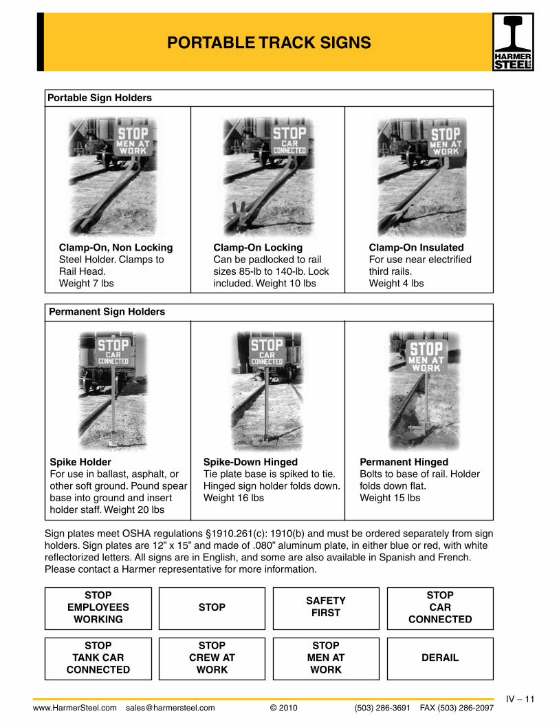
IV – 11www.HarmerSteel.com [email protected] © 2010 (503) 286-3691 FAX (503) 286-2097
PORTABLE TRACK SIGNS
Sign plates meet OSHA regulations §1910.261(c): 1910(b) and must be ordered separately from sign holders. Sign plates are 12” x 15” and made of .080” aluminum plate, in either blue or red, with white reflectorized letters. All signs are in English, and some are also available in Spanish and French. Please contact a Harmer representative for more information.
Clamp-On, Non Locking Clamp-On Locking Clamp-On Insulated Steel Holder. Clamps to Can be padlocked to rail For use near electrified Rail Head. sizes 85-lb to 140-lb. Lock third rails. Weight 7 lbs included. Weight 10 lbs Weight 4 lbs
Portable Sign Holders
Spike Holder Spike-Down Hinged Permanent Hinged For use in ballast, asphalt, or Tie plate base is spiked to tie. Bolts to base of rail. Holder other soft ground. Pound spear Hinged sign holder folds down. folds down flat. base into ground and insert Weight 16 lbs Weight 15 lbs holder staff. Weight 20 lbs
Permanent Sign Holders
STOPEMPLOYEES
WORKINGSTOP
STOPTANK CAR
CONNECTED
STOPCREW AT
WORK
STOPMEN ATWORK
STOPCAR
CONNECTED
DERAIL
SAFETYFIRST

IV – 12(503) 286-3691 FAX (503) 286-2097 © 2010 www.HarmerSteel.com [email protected]
BUMPING POSTS
TYPE BUMPING POST APPLICATION
WK Recommended for industry stub end tracks with three car capacity or less, without descending grades to track end. Weight – 705 lbs.
WD General service. Long industrial tracks outside of buildings, flat switching yards, no descending grades or hazards at track end. Installation-strengthening “middle rails” can be used with this post. Weight – 800 lbs.
WG For active track, where frequent striking face contact demands greater car stopping ability; any spur downgrade towards post; within buildings; metropolitan flat switching yards and TOFC track-ends. Installation-strengthening “middle rails” can be used with this post. Weight – 1250 lbs.
WA The strongest post ever built as a standard product. For track-end service where greatest car-stopping ability is needed. Lay track with the heaviest rail available, use full-spike ties and plenty of good ballast, and tamp thoroughly. Installation-strengthening “middle rails” can be used with this post. Weight – 1655 lbs.
All standard Bumping Posts are made in one size which will fit any rail from 5 to 7-1/2 inches high (except Type WA which fits any rail from 5-3/8 to 8 inches high). For rail smaller than 5 inches or larger than 7-1/2, inches please give height of rail.
Cross Track Spacer – holds track to gage at tension end (front).
Tension Members – impact tends to pull rails upward and toward each other.
Head – readily accepts impact of coupler and transmits it to tension and compression members.
Compression Members – Resists forward and down forces from the head and tension members, providing direct path for energy travel to ballast.
Cross Track Tie Bar – Prevents rail spreading at compression end (rear).

IV – 13www.HarmerSteel.com [email protected] © 2010 (503) 286-3691 FAX (503) 286-2097
BUMPING POSTS
The Shock-Free Head pays for itself at every installation by prolonging bumper post life, cutting equipment damage at track-ends, and doing its share to decrease Loss & Damage claims.
This rugged unit takes about thirty minutes to install, but can mean the difference between a troublesome and trouble-free track-end. Thousands are proving it every day around the world.
The Shock-Free Head is a 435 pound cushioning unit which is applied to a railroad bumping post after it is in track. It slips over the regular bumping post head and is made a part of the post by tightening the six cap screws that come with it.
Train impact is absorbed by compressing eight heavy springs which “float” between laminated rubber and fiber shock pads. As the head compresses 1-5/8” from first coupler contact, the draft gear mechanism in the car comes into operation. At normal switching speed, the result is a shock-free final impact, protecting the bumping post, the car and the lading.
Specific installation instructions are included with each unit. However, time and experience have established several measures that must be taken to insure a maximum service life from your bumping post investment.
Much of the car-stopping effectiveness of any bumping post depends upon the track to which it is secured. This is the post’s “foundation” and it should be as adequate to the job as the foundation for any other type of structure.
Generally, the heavier the rail, the better the foundation. Use sound ties, fully spiked, and full-bolted rail joints ahead of the post. Be sure you have good, well-tamped ballast.
A special feature (rail clips on rear crossmember) furnished with types WD, WG and WA Bumping Posts allows the use of “middle rails.” These “helper” rails are supplied by the customer and should be spiked between the running rails to increase track strength. Two pieces of heavy rail not less than 18 feet long should be used. These pieces of rail should extend about three feet beyond the post toward the rear and should be spiked for their entire length. A drawing displaying a typical installation with “middle rails” is shown at left.
MiddleRail
CrossAngle
CrossAngle
Left H BeamRight H Beam

IV – 14(503) 286-3691 FAX (503) 286-2097 © 2010 www.HarmerSteel.com [email protected]
DERAILS
Derails are safety devices designed to limit the movement of a car or locomotive beyond a fixed point. They operate with the use of a “shoe” that sits on top of the rail and causes any wheels passing over it to derail. When travel into the restricted area is necessary, the shoe is removed. Derails are frequently used to protect areas where people are working, loading docks, or to prevent cars from rolling out of an industrial track onto the railway mainline.
The two derails shown on this page are of welded steel construction and are the heaviest models available. Somewhat lighter models are also available, as well as portable derails, and derails equipped with blue warning flags. Most derails can be padlocked in position to protect against vandalism.
Model HB Sliding Derail is a heavy-duty derail designed for durability and to minimize stress on wheels and derail. It is operated from the side of the track with a stand that slides the shoe from the base to the upper (active) position. Pictured at left is model HB with a standard two-tie operating stand. Other types of stands are available. The stands require a connecting rod, and must be ordered separately. Weight (w/o stand) - 277 lbs.
Model EB Hinged Derail is a very common and economical derail. It has a steel base which is spiked to the ties. The shoe is on a hinge connected to the base. This derail is designed for hand throw only. The shoe is flopped over on its back in the center of the track when in the inactive position. A target stand may be used to indicate the position of the shoe. Weight - 146 lbs.
Derail Wheel CrowderIn special locations where it is absolutely necessary to derail to the inside rail of a curve or where higher speeds are anticipated, Harmer Steel recommends the use of the Derail Wheel Crowder, which assists derails by crowding the wheels into the throat or entering toe of the derail. This is significantly lower in cost than switch point and stock rail type derails.
HB Derail Crowder
Left Hand HB Derail
Tra
ck
56-1/2” Gage
15”
30”

IV – 15www.HarmerSteel.com [email protected] © 2010 (503) 286-3691 FAX (503) 286-2097
DERAILS
Derails are designed to derail to the right or the left. A right-hand or left-hand derail must be specified when ordering. Looking in the direction of movement of a car to be derailed, a right-hand derail goes on the right-hand rail and derails towards the right. A left-hand derail goes on theleft-hand rail and derails toward the left. “Double End” derails are available and may be used as right or left hand.
Model EB and HB derails come in five sizes (No. 4 through No. 8). The correct derail size is determined by the vertical distance in even inches from the top of the rail to the tie. (If tie plates are used, add the thickness of the plate under the rail to the height of the rail to determine the correct derail size. Crop the tie plate at the rail base so the derail is not partially mounted on the tie plate; the derail must sit level.) Adjustments to make the vertical distance correspond in even inches to the derail size should be made by adzing the tie under the derail or shimming up the derail with a steel shim. A derail may be used on rail 1/2” lower to 1/2” higher than the rail to which its size number refers, but the distance from the top of the rail to the surface on which the derail is secured must be even inches and must correspond to the size number of the derail.
Left-hand derail Right-hand derail
The High Rise Derail Operating Stand is primarily a one piece weldment and is shipped assembled ready for installation. The only replaceable parts are the targets, connecting rod, lamp tip (if used) and the adjustable 1 inch diameter eyebolt.
Each HRS-100 is shipped in three pieces; the primary welded unit, one connecting rod complete with adjustable clevis ends and pins, and a protective carton for the target. Weight - 180 lbs.
The standard units are equipped with red and white targets that are positioned 41-5/8” above the top of the ties. The model shown at left has the Union Pacific style purple target with white “D” which is positioned 58” above the ties. The standard unit comes with an 8’ 2” adjustable connecting rod which places the center of the target staff 8’ 10-1/4” from the center of the track.
• Ergonomicdesign• Allowsmovementofslidingderailwithoutbendingorstooping• Handle:34”abovetopoftie• Strokeadjustsforanyslidingderail• Standcanbepad-lockedinonandoff-railposition
When ordering specify:1. Target colors if other than standard2. Connecting rod length if other than standard3. Lamp tip dimensions if other than AREMA standard
Model HRS-100(with U.P. target)
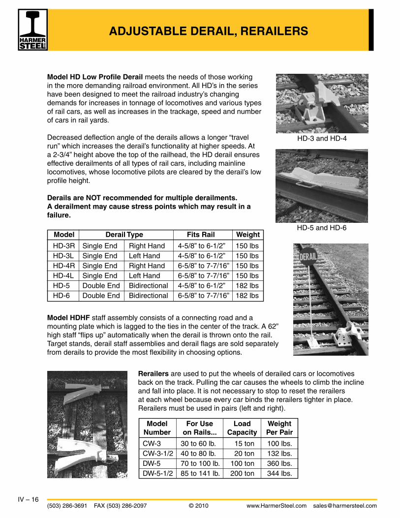
IV – 16(503) 286-3691 FAX (503) 286-2097 © 2010 www.HarmerSteel.com [email protected]
ADJUSTABLE DERAIL, RERAILERS
Model For Use Load Weight Number on Rails... Capacity Per Pair
CW-3 30 to 60 lb. 15 ton 100 lbs. CW-3-1/2 40 to 80 lb. 20 ton 132 lbs. DW-5 70 to 100 lb. 100 ton 360 lbs. DW-5-1/2 85 to 141 lb. 200 ton 344 lbs.
Model HDHF staff assembly consists of a connecting road and a mounting plate which is lagged to the ties in the center of the track. A 62” high staff “flips up” automatically when the derail is thrown onto the rail. Target stands, derail staff assemblies and derail flags are sold separately from derails to provide the most flexibility in choosing options.
Rerailers are used to put the wheels of derailed cars or locomotives back on the track. Pulling the car causes the wheels to climb the incline and fall into place. It is not necessary to stop to reset the rerailers at each wheel because every car binds the rerailers tighter in place. Rerailers must be used in pairs (left and right).
HD-3 and HD-4
HD-5 and HD-6
Model HD Low Profile Derail meets the needs of those working in the more demanding railroad environment. All HD’s in the series have been designed to meet the railroad industry’s changing demands for increases in tonnage of locomotives and various types of rail cars, as well as increases in the trackage, speed and number of cars in rail yards.
Decreased deflection angle of the derails allows a longer “travel run” which increases the derail’s functionality at higher speeds. At a 2-3/4” height above the top of the railhead, the HD derail ensures effective derailments of all types of rail cars, including mainline locomotives, whose locomotive pilots are cleared by the derail’s low profile height.
Derails are NOT recommended for multiple derailments.A derailment may cause stress points which may result in a failure.
Model Derail Type Fits Rail Weight
HD-3R Single End Right Hand 4-5/8” to 6-1/2” 150 lbs HD-3L Single End Left Hand 4-5/8” to 6-1/2” 150 lbs HD-4R Single End Right Hand 6-5/8” to 7-7/16” 150 lbs HD-4L Single End Left Hand 6-5/8” to 7-7/16” 150 lbs HD-5 Double End Bidirectional 4-5/8” to 6-1/2” 182 lbs HD-6 Double End Bidirectional 6-5/8” to 7-7/16” 182 lbs

IV – 17www.HarmerSteel.com [email protected] © 2010 (503) 286-3691 FAX (503) 286-2097
WHEEL STOPS
Model CS-2 Self Tightening Type
Durable self-tightening wheel stops use tapered wedges between the assembled castings and rail head, thus insuring perfect alignment to rail size and providingself-tightening action. This stop is assembled on head of rail by tightening five bolts, driving wedge from the rear between the assembled castings and rail head until tight. Spacer washers are provided to allow for varying head widths. Fits all rail sizes 60 to 141 lbs. Weight 220 lbs/pr.
Model SF Cushioned Type
Model SF is a heavy-duty wheel stop which utilizes the cushioning ability of the cross ties and ballast to absorb impact. It also employs the car’s weight for additional braking friction on the rail. It is made of all welded steel construction and requires tightening only four bolts for installation of each pair. Fits all rail sizes 60 to 141 lbs. Weight 350 lbs/pr.
Caution For All Wheel Stops:1. For use on level track only.2. For use with standard size freight cars only. Do not use with wheels less than 33” diameter.3. Do not use on overhead crane or other non-railroad vehicles.4. If used on flush rail, rail must be fully exposed for proper installation.5. Wheel stops must always be used in pairs with each stop in exact alignment with the other.6. Car speed at impact must not exceed normal switching speeds.7. Check stops periodically to be sure bolts are tight.8. Failure to adhere to these instructions can cause product to fail.
Model CS-60 Hinged Type
Model CS-60 is a hinged-type car stop designed for permanent installation on either flush or exposed rails. In the raised position, the CS-60 protects workers, warehouse doors, crossover walks, etc., or it swings down out of the way. The CS-60 may be padlocked in either the up or down position. Specify rail size when ordering. Weight 180 lbs/pr.

IV – 18(503) 286-3691 FAX (503) 286-2097 © 2010 www.HarmerSteel.com [email protected]
Single Chocks
Style D without Flag, Exposed Rails, 6 lbs Style A with Flag, Exposed Rails, 13 lbsStyle D-1 without Flag, Flush Rails, 8 lbs Style A-1 with Flag, Flush Rails, 13 lbs
Double Chocks
Style B without Flag, Exposed Rails, 12 lbs Style C with Flag, Exposed Rails, 16 lbsStyle B-1 without Flag, Flush Rails, 12 lbs Style C-1 with Flag, Flush Rails, 16 lbs
Style B-2 without Flag, w/Tightener, Exposed Rails, 16 lbsStyle C-2 with Flag & Tightener, Exposed Rails, 20 lbs
WHEEL CHOCKS
What Kind of Rail Do You Have?
Exposed Flush
Use: A, B, B-2, Use: A-1, B-1, C-1, D-1 C, C-2, D
Chock
Tie
Chock
InsideFlangewayfor Wheel
PavingPaving

IV – 19www.HarmerSteel.com [email protected] © 2010 (503) 286-3691 FAX (503) 286-2097
TRACK REPAIR EQUIPMENT
Anti-Slip Rail Tongs are used on cranes for rail handling projects. They will lift any 39 foot tee rail section up to and including 155 lb rail and crane rail up to 171 lb by either the head or the base. No adjustments are necessary to handle various sizes of rail. Tongs are designed for lifting, not dragging. The anti-slip feature of the tongs is due to the sliding toggle action of the links when a rail is lifted. In this way the angularity of the toggle links is never less than 90 degrees with respect to each other. Weight - 60 lbs.
Rail-Pull brings rail back into gage after derailment so rerailing can proceed. Cars can freely pass over rail-pull clamp plates.Weight 76 lbs.
Clamping Rail Tong for crane rail 135 lb., 171 lb. and 175 lb. Load capacity 4000 lbs. Lift only –no dragging. Weight 60 lbs.
Rail Tugger has a self-locking wedge to tightly grab rail for easy pulling and positioning of rail lengths. Handles rails from 100 to 141 lbs/yd. Weight 40 lbs.
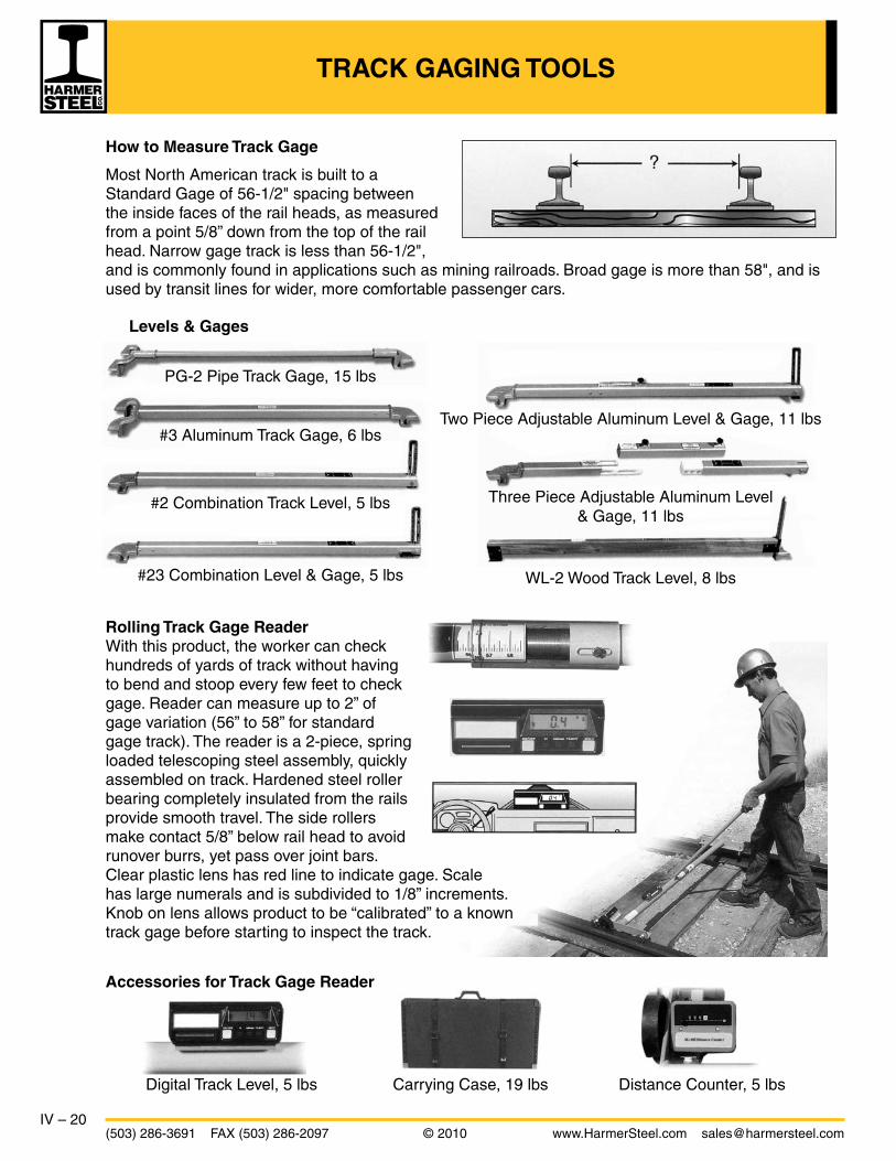
IV – 20(503) 286-3691 FAX (503) 286-2097 © 2010 www.HarmerSteel.com [email protected]
TRACK GAGING TOOLS
How to Measure Track Gage
Most North American track is built to a Standard Gage of 56-1/2" spacing between the inside faces of the rail heads, as measured from a point 5/8” down from the top of the rail head. Narrow gage track is less than 56-1/2", and is commonly found in applications such as mining railroads. Broad gage is more than 58", and is used by transit lines for wider, more comfortable passenger cars.
Levels & Gages
PG-2 Pipe Track Gage, 15 lbs
#3 Aluminum Track Gage, 6 lbs
#2 Combination Track Level, 5 lbs
#23 Combination Level & Gage, 5 lbs
Two Piece Adjustable Aluminum Level & Gage, 11 lbs
Three Piece Adjustable Aluminum Level & Gage, 11 lbs
WL-2 Wood Track Level, 8 lbs
Accessories for Track Gage Reader
Digital Track Level, 5 lbs Carrying Case, 19 lbs Distance Counter, 5 lbs
Rolling Track Gage ReaderWith this product, the worker can check hundreds of yards of track without having to bend and stoop every few feet to check gage. Reader can measure up to 2” of gage variation (56” to 58” for standard gage track). The reader is a 2-piece, spring loaded telescoping steel assembly, quickly assembled on track. Hardened steel roller bearing completely insulated from the rails provide smooth travel. The side rollers make contact 5/8” below rail head to avoid runover burrs, yet pass over joint bars. Clear plastic lens has red line to indicate gage. Scale has large numerals and is subdivided to 1/8” increments. Knob on lens allows product to be “calibrated” to a known track gage before starting to inspect the track.

IV – 21www.HarmerSteel.com [email protected] © 2010 (503) 286-3691 FAX (503) 286-2097
RAIL BENDERS
Hydraulic Rail Benders for light rails are the double hook type with a 25 ton hydraulic ram-pump or 50 ton ram with remote pump. They provide direct 90 degree pressure against the rail head between the hooks. The underlipped hooks of the frame have convex bearing surfaces to prevent crawling off the rail. The hydraulic benders are much easier to use than the manual screw type.
Do not use operating bar other than furnished.
Screw Type Rail Benders for light rails are designed with double-hook style cast steel frame and provide direct 90 degree bearing to the rail head. The operator uses a steel bar to turn the screw.
Jack-Type Rail Benders are available in 25 ton, 35 ton, and 50 ton series. Benders consist of a steel frame, (one end of which fits over the ball of the rail, the other end is seated on the top of the jack), a safety cable, a jack, and a lever bar. They make stock and guard rail bends conveniently. A 50 ton bender will reliably generate 100,000 pounds of bending force and is especially well-suited to bending newer high-Brinell rail. A safety cable prohibits jack from slipping out of place. Rugged, but lighter weight than similar benders of same capacity. Built-in scale assures accurate duplication of bends.
Model Max Max Rail Weight Bend Size
25 ton 5-1/2" 110 lbs/yd 180 lbs
35 ton 5-1/2" 132 lbs/yd 190 lbs
50 ton (T Rail) 6” 141 lbs/yd 361 lbs
50 ton (Undercut) 6” 141 lbs/yd 361 lbs
Model Style For Rails Weight
3H50 50 ton ram 25-60 lbs/yd 127 lbs
2H50 50 ton ram 60-85 lbs/yd 170 lbs
MS2 Manual Screw 60-85 lbs/yd 100 lbs
3H 25 ton ram 25-60 lbs/yd 95 lbs
2H 25 ton ram 60-70 lbs/yd 138 lbs
MS1 Manual Screw 25-60 lbs/yd 72 lbs

IV – 22(503) 286-3691 FAX (503) 286-2097 © 2010 www.HarmerSteel.com [email protected]
TRACK TOOLS
Tie & Timber Tools
Key Description Weight Jaw Lbs. Opening
1 Timber Bar 17 – 2 Nipping Bar 18 – 3 Nipping Fork 17 – 4 Adze with handle 8 – 5 Tie Plug Punch 7 – 6 Tamping Bar 15 – 7 Hexagonal Telegraph Digging Bar 28 – 8 Skidding Tongs 10 21” 9 Two-Man Timber Tong 12 15-1⁄2” 10 Timber Dragging Tongs 15 20” 11 Tie Carrier (Crane Type) 37 19” 12 Timber Carrier (Crane Type) 51 29” 13 Aluminum Tie Tong 9 15-1⁄2”
With Replaceable Tips 14 One-Man Tie Tongs 10 15-1⁄2”
Ballast Tools
Key Description Weight Lbs.
1 Ballast Shovel (Steel Handle) 10 2 Ballast Shovel (Wood Handle) 8 3 Switch Broom (PoIypropyIene Bristles) 5 4 Clay Pick 8 5 Ballast Fork (8 Tines) 6 6 Ballast Fork (10 Tines) 7 7 Aluminum Shovel (5-3⁄4” Blade) 2.6 8 Aluminum Shovel (9-1⁄4” Blade) 3.5
8 9 10 11 12 13 14
1
2
3
4
5
6
7
1
2
3 4
5
6
7
8

IV – 23www.HarmerSteel.com [email protected] © 2010 (503) 286-3691 FAX (503) 286-2097
TRACK TOOLS
Spike Handling Tools
Key Description Weight/Lbs. Jaw Opening
1 4-Knob Spike Puller 3 3/4” 2 Dome Head Spike Socket 5 – 3 Spike Maul 11 – 4 Track Spike Lifter 7.5 – 5 Sledge Hammer 8 – 6 Sledge Hammer 10 – 7 Claw Bar 27 9/16” x 5/8”
Rail Handling Tools
Key Description Weight Jaw Nut Lbs. Opening Size
1 Steel Drift Pin, Sml 3⁄8” Point 4 – – 2 Steel Drift Pin, Med 9⁄16” Point 5 – – 3 Steel Drift Pin, Lrg 3⁄4” Point 5 – – 4 Two-Man Rail Tong 18 3-3/4” – 5 Track Punch, Round C 8 – – 6 Alloy Track Chisel 7 – – 7 Bond Removal Punch 4 – – 8 Cross-Cut Chisel 3 – – 9 Rail Fork 13 – – 10 Ratchet Action Track Wrench 8 1-1⁄2” – 11 Ratchet Action Track Wrench 10 1-11⁄16” – 12 Ratchet Action Track Wrench 10 1-7⁄8” – 13 Double End Track Wrench 12 1-1/2” to 1-7⁄16” to 1-11⁄16” 1-5⁄8” 14 Double End Track Wrench 14 1-11⁄16” to 1-5⁄8” to 1-7⁄8” 1-13⁄16” 15 Double End Track Wrench 15 1-7⁄8” to 1-13⁄16” to 2-1⁄16” 2” 16 Double End Track Wrench 16 2-1⁄16” to 2” to 2-1⁄4” 2-3⁄16” 17 Single End Track Wrench 8 1-5⁄16” 1-1⁄4” 18 Single End Track Wrench 12 1-5⁄8” 1-5⁄8” 19 Single End Track Wrench 14 1-7⁄8” 1-13⁄16” 20 Rail Anchor Applicator 28 – – 21 Wedge Point Lining Bar 18 – – 22 Wedge Point Lining Bar 22 – – 23 Wedge Point Lining Bar 26 – – 24 Diamond Point Lining Bar 18 – – 25 Diamond Point Lining Bar 26 – – 26 Pinch Point Lining Bar 18 – – 27 Pinch Point Lining Bar 26 – –
1 2
3
4
5, 6
7
1, 2 3
4
5
6
7
8
9
10, 11, 12
13, 14, 15, 16
17, 18, 19
20
21, 22, 23
24, 25
26, 27

IV – 24(503) 286-3691 FAX (503) 286-2097 © 2010 www.HarmerSteel.com [email protected]
TRACK JACKS, TRACK LINERS
Track Liners are a husky, low-cost maintenance tool. Together with a lining bar (sold separately), this device is used to align tangent and curved track. Years of satisfactory service to the industry have identified these desirable features:
• Linersdonothumptrack• Nodiggingatendoftiesisnecessary• Light,compact-linerweighsonly28lbs• Builtforheavydutyandlonglife• Forwardmovementcomesfromliftingonliningbar
- safer and more effective than downward pull
Caution: Quick-Trip Track Jacks are intended for use only in railway track maintenance and are trip lowering. Trip lowering jacks quickly drop the load and cannot be safely lowered incrementally. They should not be used for general purpose lifting.
Track Jacks are used for a variety of track maintenance jobs such as surfacing, tamping, and lining track. Rugged construction permits full capacity to be used on the toe or cap of the jack. The jacks are designed to be used in conjunction with a lining bar (sold separately, see page IV-23) which fits into the square socket hole at the backside of the jack. Ratchet level jacks work on the same principle as automatic tire jacks: load is raised or lowered “tooth-by-tooth.” Jack cannot be tripped under load. Quick-Trip jacks have “quick-trip” feature when under load. Requires skilled operator.
Cap/Retractor Minimum Minimum Toe Model Capacity Height Retractor Height Weight Lift
AL-87 5 tons 17” 10” 1-5/8” 30 lbs
AL-88 10 tons 20-1/2” 12” 2” 42 lbs
AL-89 15 tons 23-1/4” 13” 2-1/2” 93 lbs
Hydraulic 10 tons 22” 9” 2” 50 lbs
Manual 15 tons 11” 5-1/4” 2” 30 lbs
Manual 15 tons 22-5/8” 13” 2” 49 lbs
AL-87 AL-88 AL-89 Hydraulic Manual
Ratchet Lever Jacks “Quick-Trip” Jacks

V – 1www.HarmerSteel.com [email protected] © 2010 (503) 286-3691 FAX (503) 286-2097
TURNOUTS
The following pages show the standard design of the various components that make up a turnout. Designs shown are those most commonly specified, and can be modified to accommodate individual requirements. Turnouts for mining and tunneling applications can be mounted on steel ties andpre-assembled, or they can be shipped in components for assembly on site.
Standard Complete Turnout
Track-Work Formations
Diamond Straight Crossing
Left Hand Crossover Crossing
Left Hand Turnout Double Hand Crossover
Right Hand Turnout
Equilateral Turnout Right Hand Crossover 3 Way Turnout
Switch stand
Switch throwSwitch point (LH)
Middle ordinate
Actual lead
Lengthof switch
Heel spread
Actualfrog point
Guard rail
Frog
Toe Heel
Frog length
Curved stock rail Guard rail
Straight closure rail
Outside radius
Curved closure rail
Switch rodSide jaw clipSwitch point (RH)
Vertexdistance
Gage
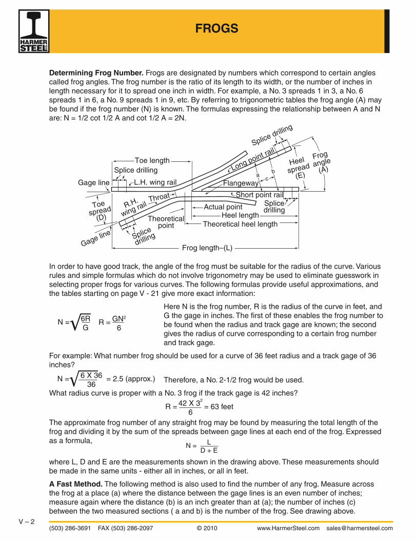
V – 2(503) 286-3691 FAX (503) 286-2097 © 2010 www.HarmerSteel.com [email protected]
Determining Frog Number. Frogs are designated by numbers which correspond to certain angles called frog angles. The frog number is the ratio of its length to its width, or the number of inches in length necessary for it to spread one inch in width. For example, a No. 3 spreads 1 in 3, a No. 6 spreads 1 in 6, a No. 9 spreads 1 in 9, etc. By referring to trigonometric tables the frog angle (A) may be found if the frog number (N) is known. The formulas expressing the relationship between A and N are: N = 1/2 cot 1/2 A and cot 1/2 A = 2N.
In order to have good track, the angle of the frog must be suitable for the radius of the curve. Various rules and simple formulas which do not involve trigonometry may be used to eliminate guesswork in selecting proper frogs for various curves. The following formulas provide useful approximations, and the tables starting on page V - 21 give more exact information:
Here N is the frog number, R is the radius of the curve in feet, and G the gage in inches. The first of these enables the frog number to be found when the radius and track gage are known; the second gives the radius of curve corresponding to a certain frog number and track gage.
For example: What number frog should be used for a curve of 36 feet radius and a track gage of 36 inches?
Therefore, a No. 2-1/2 frog would be used.
What radius curve is proper with a No. 3 frog if the track gage is 42 inches?
The approximate frog number of any straight frog may be found by measuring the total length of the frog and dividing it by the sum of the spreads between gage lines at each end of the frog. Expressed as a formula,
where L, D and E are the measurements shown in the drawing above. These measurements should be made in the same units - either all in inches, or all in feet.
A Fast Method. The following method is also used to find the number of any frog. Measure across the frog at a place (a) where the distance between the gage lines is an even number of inches; measure again where the distance (b) is an inch greater than at (a); the number of inches (c) between the two measured sections ( a and b) is the number of the frog. See drawing above.
Frog length–(L)
Toe length
Short point rail
Long point rail
R.H.
wing rail
L.H. wing rail
Theoreticalpoint
Actual pointHeel length
Theoretical heel length
Throat
Splice drilling
Heel
spread(E)
Frogangle
(A)
Toespread
(D)
Splice
drilling
Splicedrilling
Flangeway
Gage line
Gage line
Splice drillinga b
c
N = 6R G
R = GN2
6
N = 6 X 36 = 2.5 (approx.) 36
R = 42 X 32 = 63 feet 6
N = L D + E
FROGS

V – 3www.HarmerSteel.com [email protected] © 2010 (503) 286-3691 FAX (503) 286-2097
1-5/8” Flangeway(20 lb to 40 lb rail, inclusive)1-3/4” Flangeway(60 lb rail)
Design 97
Welded Plate Frog Design 97 is recommended for use in mines, construction work and industrial plants where light rails are used.
Design 289
Design 289 is of one-piece construction, made of cast manganese steel. Being of one piece, it has no rivets or plates to work loose. It may be quickly installed, and will outwear several plate frogs. No splice bars are required, the rails being bolted directly to the plate arms, and special long heat-treated bolts with beveled washers are furnished where necessary. Frogs are made with 1/2 inch points.
FROGS FOR LIGHT RAILS

V – 4(503) 286-3691 FAX (503) 286-2097 © 2010 www.HarmerSteel.com [email protected]
SOLID MANGANESE SELF-GUARDED FROGS
A Solid Manganese Steel Self–Guarded Frog is constructed with guides or flanges above its running surface. These flanges contact the tread rims of the wheels and safely guide the wheel flanges past the point of the frog. Thus, the self-guarded frog does not require the use of guard rails. This type of frog is used for yard tracks and main line tracks where the speed does not exceed30 mph.
Quantities of Hook Twin Tie Plates
5-1/2” Base Rail Frog L23 L27 H23 H27 H31 H35 LR23 LR27 LR31
5 4 2 4 2 0 2 0 2 0
6 4 2 4 2 0 2 0 2 2
7 4 4 2 4 0 2 2 2 2
8 6 4 4 4 2 0 0 4 2
9 6 4 4 6 0 0 2 4 2
10 6 4 6 6 2 0 2 4 2
6” Base Rail Frog L23 L27 H23 H27 H31 H35 LR23 LR27 LR31
5 4 2 4 2 0 2 0 2 0
6 4 2 4 2 2 2 0 2 2
7 4 2 4 4 2 2 0 2 2
8 4 4 4 4 2 2 0 4 2
9 4 4 6 6 2 0 0 4 2
10 6 4 6 6 2 0 2 4 2
Standard AREMA Frog LengthsRails 112 lb. or Heavier
Frog No. Total Length Toe Length Heel Length
4 5’11” 2’1” 3’10”
5 6’5” 2’1” 4’4”
6 7’4” 2’11” 4’5”
7 8’1-1/2” 2’11” 5’2-1/2”
8 8’11” 2’11” 6’0”
9 9’9” 2’11” 6’10”
10 11’4-1/2” 3’9” 7’7-1/2”
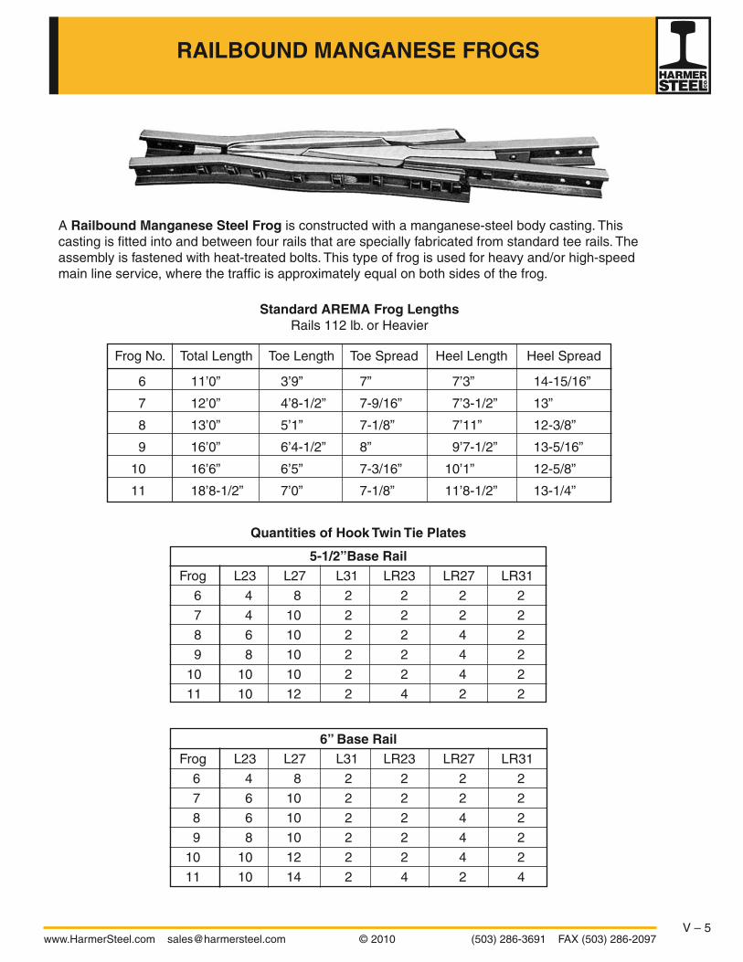
V – 5www.HarmerSteel.com [email protected] © 2010 (503) 286-3691 FAX (503) 286-2097
RAILBOUND MANGANESE FROGS
A Railbound Manganese Steel Frog is constructed with a manganese-steel body casting. This casting is fitted into and between four rails that are specially fabricated from standard tee rails. The assembly is fastened with heat-treated bolts. This type of frog is used for heavy and/or high-speed main line service, where the traffic is approximately equal on both sides of the frog.
Quantities of Hook Twin Tie Plates
5-1/2”Base Rail Frog L23 L27 L31 LR23 LR27 LR31
6 4 8 2 2 2 2
7 4 10 2 2 2 2
8 6 10 2 2 4 2
9 8 10 2 2 4 2
10 10 10 2 2 4 2
11 10 12 2 4 2 2
6” Base Rail Frog L23 L27 L31 LR23 LR27 LR31
6 4 8 2 2 2 2
7 6 10 2 2 2 2
8 6 10 2 2 4 2
9 8 10 2 2 4 2
10 10 12 2 2 4 2
11 10 14 2 4 2 4
Standard AREMA Frog LengthsRails 112 lb. or Heavier
Frog No. Total Length Toe Length Toe Spread Heel Length Heel Spread
6 11’0” 3’9” 7” 7’3” 14-15/16”
7 12’0” 4’8-1/2” 7-9/16” 7’3-1/2” 13”
8 13’0” 5’1” 7-1/8” 7’11” 12-3/8”
9 16’0” 6’4-1/2” 8” 9’7-1/2” 13-5/16”
10 16’6” 6’5” 7-3/16” 10’1” 12-5/8”
11 18’8-1/2” 7’0” 7-1/8” 11’8-1/2” 13-1/4”

V – 6(503) 286-3691 FAX (503) 286-2097 © 2010 www.HarmerSteel.com [email protected]
A Solid Manganese Steel Flat–Top Frog is essentially a one-piece casting made of manganese-steel. This type of frog may be used as an alternative to a railbound manganese-steel frog for heavy main line slow-speed traffic.
RIGID BOLTED & MANGANESE FLAT-TOP FROGS
This Rigid Bolted Frog is manufactured strictly in accordance with the AREMA specifications. It is durably constructed of rolled steel filler, steel rail heel riser, cast iron toe and heel blocks, and heat-treated bolts applied with driving fit in the holes. It is furnished with extended points and a 45 degree bevel on the wing rails. This frog is recommended for heavy duty yard use and medium speed turnouts. (Number of hook twin tie plates depends on frog number; above quantities shown for example only.)
L27 L27 L23 L23 L23 L23 L23 L27 L23 LR23 LR27 LR27 LR31
Frog lengthHeel length
Toe length1/2 point
Standard AREMA Frog LengthsRails 112 lb. or Heavier
Frog No. Total Length Toe Length Heel Length Toe Spread Heel Spread
4 5’11” 2’1” 3’10” 5-11/16” 12”
5 6’5” 2’1” 4’4” 4-1/2” 10-7/8”
6 7’4” 2’11” 4’5” 5-5/16” 9-5/16”
7 8’1-1/2” 2’11” 5’2-1/2” 4-1/2” 9-13/32”
8 8’11” 2’11” 6’0” 3-7/8” 9-1/2”
9 9’9” 2’11” 6’10” 3-3/8” 9-19/32”
10 11’4-1/2” 3’9” 7’7-1/2” 4” 9-5/8”
11 12’2-1/2” 3’9” 8’5-1/2” 3-9/16” 9-23/32”
12 13’0” 3’9” 9’3” 3-1/4” 9-3/4”

V – 7www.HarmerSteel.com [email protected] © 2010 (503) 286-3691 FAX (503) 286-2097
A Guard Rail is a rail laid parallel with the running rails to hold wheels in correct alignment. Guard rails are most commonly used opposite a frog where they prevent derailments and protect the point of the frog.
American Mining Congress Design guard rails (shown below) are used with light rails in mines and industrial plants. They have the flares bent and the flanges removed, and are equipped with blocks and bolts for mounting onto the stock rails. American Mining Congress recommended lengths are 4’ 6” for No. 2, 2-1/2 and 3 frogs; 6’ 0” for No. 4, 5 and 6 frogs and 8’ 3” for No. 7 and No. 8 frogs. A 1-5/8” flangeway width is standard for rails up to 75 lb. A 1-7/8” flangeway width is standard on 80 lb and above.
AREMA Design guard rails are planed and beveled, and are equipped with distinct end and separator blocks. These blocks come complete with bolts, nuts, spring washers, head locks and web washers. These guard rails are commonly used with single plates (either flat or shouldered) or twin tie plates (either flat or hook). The standard lengths, and quantities of blocks and single plates are given in the tables below.
GUARD RAILS
Center of guard rail
9” Separator block1-7/8”
2-1/2”3-1/2”+4’0-1/2”
5”4’0-1/2”
12” 24”3’5” Straight guarding face
24” 12”9’5”
Base -1/8”
Length to suit rail section
7”or8”
3/4”
3” Head+Base+FLGY-1/16”
3/8”
1-7/8”+ 1-7/8”+
Flangeway width
7/8”
1-7/8”
1”Section thruend block Section thru
separation block
Guard-rail tie plate
AREMA Design Plan 504-71
Length Separator End Plates Block Block
9’5” 1 2 7
12’6” 2 2 9
15’0” 2 2 10
AREMA Design Plan 504-89
Length Separator End Plates Block Block
13’0” 2 2 9
16’6” 3 2 11
20’0” 4 2 13

V – 8(503) 286-3691 FAX (503) 286-2097 © 2010 www.HarmerSteel.com [email protected]
Foot guard
Running rail canted or vertical(as specified)
Rivets
Section at end of guard rail Section between ties
Single shoulder
1” diameter bolt
Flangeway width
Depressedhook flange
Foot guardFoot guard
4”±25°
5/8”
19-1/2” 19-1/2” 19-1/2” 19-1/2” 19-1/2”5-1/4” 5-1/4”
1’4” 1’4”1’8”1’8” 3’0” straightguarding face
9’0”
One-piece guard rails are manufactured with plates integral with the guard rail, and the unit is shipped in one piece ready to install. It is not necessary to field-drill holes in the running rail and there are no separator blocks to vibrate loose. Staggered holes in the plates generally allow leeway for gaging guard rail with frog, and use with more than one rail section. These guard rails can be supplied level with the running rail, but a height 1/4” higher than running rail is recommended where conditions permit. In any case, the height should not be more than 1” above the top of the running rail. Some railroads specify guard rails of different heights for the same turnout, with the high guard rail to be placed on the turnout side of the frog.
Hook-flange guard rails (below) are manufactured from rail sections rolled especially for this guard rail.
Manganese one-piece guard rails (below) consist of a single casting of manganese steel with a reinforced head and corrugated web. They come in a variety of lengths and are marked with the year cast and the height of the guard rail.
“A”
Guardface
Optionalraised guard
Cross section “A-A”
“B”“A”
“B”
D
E
Hei
ght
C B CA
Length
Cross section “B-B”
ONE–PIECE GUARD RAILS

V – 9www.HarmerSteel.com [email protected] © 2010 (503) 286-3691 FAX (503) 286-2097
Shown below are end views of typical switch point constructions. The drawing on the top left shows a Samson (detail 5100) construction, while the other three show the standard Knife-blade (detail 6100) construction. Samson switch points are used on main line or heavy duty locations. Knife-blade points are generally used for industrial and yard applications. Non-reinforced switch points are typical for rails lighter than 90-lb. used for mining or tunneling. Single-reinforced switch points are commonly used for industrial tracks, and double reinforced are used in heavier duty locations.
Shown below are the three most common types of switch point clips. These clips are attached to the switch point using the two upper holes. The lower holes are used for connecting to the switch rod, The proper switch rod is determined by the type of switch point clip used. Both the transit and Eureka clips allow for adjustment of the spacing between switch points. The side-jaw clips are not adjustable.
Transit Clip Side-Jaw Clip Adjustable Side Jaw Clip (“Eureka Clip”)
SWITCH POINT DETAILS
Thickness of point
Double ReinforcedKnife-Blade (Detail 6100)
Reinforcing barsSpring washer
NutCotter
Non-ReinforcedKnife-Blade (Detail 6100)
Thickness of point
Cotter
Single ReinforcedKnife-Blade (Detail 6100)
Thickness of pointReinforcing barSpring washer
Nut
Double ReinforcedSamson (Detail 5100)
(Note: undercutrequired on stock rail)
0° pointReinforcing bars
Spring washerNut
Cotter

V – 10(503) 286-3691 FAX (503) 286-2097 © 2010 www.HarmerSteel.com [email protected]
20”
No. 1G No. 1A No. 1 No. 1 No. 1 No. 1 No. 1 No. 2 No. 3
5” 3” 5” 5” 5” 5” 5” 5” 5”10” 15”10” 15” 15” 15” 13”10” 10”
5” 5” 5”
Vertical Bend3’-6”3’-9”Top Cut 7’-0”
14’-6”
1-1/2”Per Point Detail
Base of Stock Rail
B B B B B B B B B B B B B B B 1/4” 1/4”
Elevation of Switch Point1/4” 1/8”
1-1/2”
0”
20” 20” 20” 20” 20-1/2” 21”21-1/2”22”
20” 22”
No. 3No. 2
No. 1PNo. 1P
No. 1
No. 1P
No. 1No. 1ANo. 1GNo. 0
20”
Left Hand Switch Point
Right Hand Switch Point
Stop
Vertex DistanceFor PointDetail 6100
Point of Switch
3”
4-1/8”
Gag
e 4’
8-1
/2” 12”
6’-9
” Lo
ng
4’-0
” Lo
ngT
ie R
od
Hea
d R
od6’
-0”
Long
4-3/4” Throw
Plan of Left Hand Switch Layout16’-6”
4’-3”52”
Shown on these two pages is a typical switch layout for a 16’6” straight split switch with graduated risers. This switch is typically used for number seven through number ten turnouts. The layout here is shown for a left-hand turnout, but the components are the same for either a left or right-hand configuration. Switches like this one can be supplied with either rigid or adjustable braces. The adjustable braces are more expensive, but are preferred in heavier duty applications. The illustration above shows both rigid and adjustable brace options. The rigid brace plating pattern is shown on the rail at the top of the page and the adjustable brace pattern is shown on the rail below. The actual layout would follow one pattern or the other; either all rigid or all adjustable braces. Listed on the opposite page is a typical bill of materials for a 16’6” switch with adjustable braces. The gage plates and switch rods can be supplied with insulation if necessary. The bill of materials is frequently changed to accommodate specific customer preferences. Common changes include: substituting rigid for adjustable braces, adding the No. 0 plates, and using flat twin or fewer hook twin tie plates.
16’6” STRAIGHT SPLIT SWITCH WITHGRADUATED RISERS

V – 11www.HarmerSteel.com [email protected] © 2010 (503) 286-3691 FAX (503) 286-2097
L LR 23 23
L LR 23 23
L LR 23 23
L LR 27 27
L LR 27 27
L LR 27 27
L LR 27 27
L LR31 31
L LR31 31
L LR31 31
L LR31 31
L LR 27 27
L LR 27 27
L LR 27 27
L LR 27 27
L LR 23 23
L LR 23 23
L LR 23 23
Sho
ulde
r B
olts
Spread at Heel = 6-1/4”Angle of Switch, 1°-46’-22”
20”
StandardTie Plates
10” 10”
20”
2’-3”
Typical bill of materials:
1 pair 16’6” Single Reinforced Switch Points with transit clips 1 each Non-Insulated Head Rod 1 each Non-Insulated Tie Rod 1 each Non-Insulated Gage Plate (No. 1G) with adjustable braces 8 each Brace Plates with adjustable braces (2 ea. No. 1A, 4 ea. No. 1, and 2 ea. No. 2) 6 each Shoulder Slide Plate (No. 1P) 2 each Plain Plate (No. 3) 4 each Heel Plates 36 each Hook Twin Tie Plates (6-L23, 6-LR23, 8-L27, 8-LR27, 4-L31, 4-LR31) 1 pair Single Hole Floating Heel Block Assemblies complete 1 each Switch Stand with Connecting Rod
16’6” STRAIGHT SPLIT SWITCH WITHGRADUATED RISERS
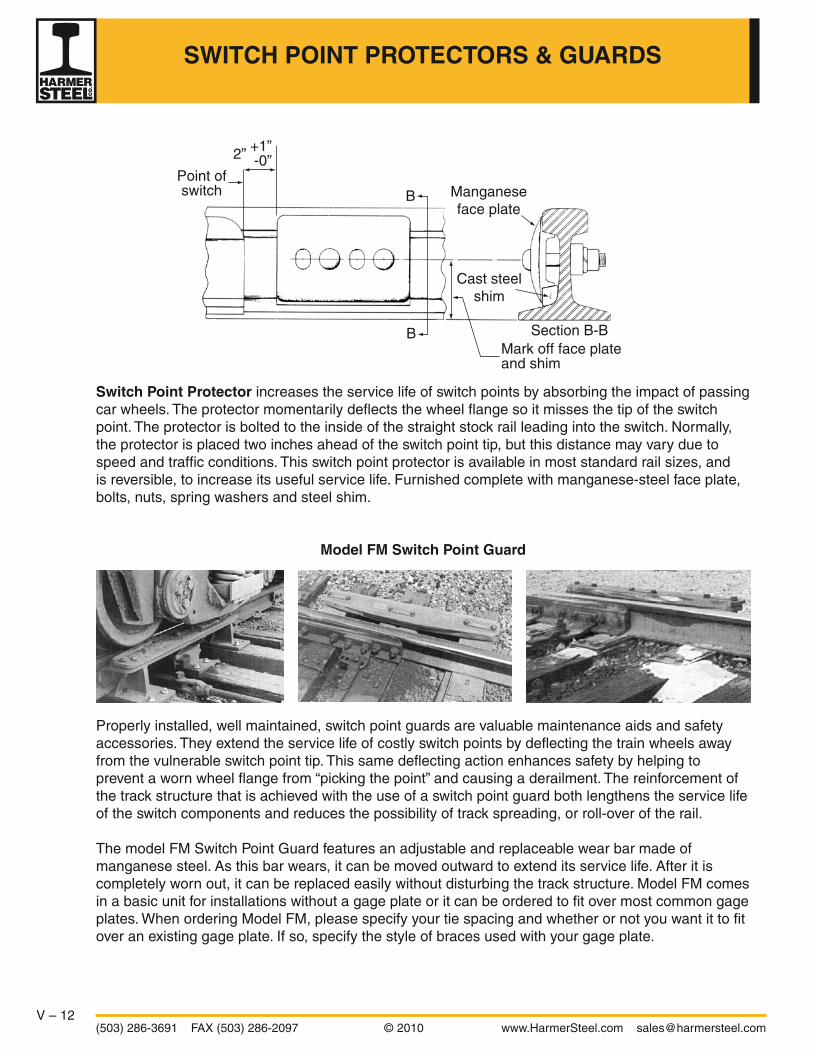
V – 12(503) 286-3691 FAX (503) 286-2097 © 2010 www.HarmerSteel.com [email protected]
Switch Point Protector increases the service life of switch points by absorbing the impact of passing car wheels. The protector momentarily deflects the wheel flange so it misses the tip of the switch point. The protector is bolted to the inside of the straight stock rail leading into the switch. Normally, the protector is placed two inches ahead of the switch point tip, but this distance may vary due to speed and traffic conditions. This switch point protector is available in most standard rail sizes, and is reversible, to increase its useful service life. Furnished complete with manganese-steel face plate, bolts, nuts, spring washers and steel shim.
Model FM Switch Point Guard
Properly installed, well maintained, switch point guards are valuable maintenance aids and safety accessories. They extend the service life of costly switch points by deflecting the train wheels away from the vulnerable switch point tip. This same deflecting action enhances safety by helping to prevent a worn wheel flange from “picking the point” and causing a derailment. The reinforcement of the track structure that is achieved with the use of a switch point guard both lengthens the service life of the switch components and reduces the possibility of track spreading, or roll-over of the rail.
The model FM Switch Point Guard features an adjustable and replaceable wear bar made of manganese steel. As this bar wears, it can be moved outward to extend its service life. After it is completely worn out, it can be replaced easily without disturbing the track structure. Model FM comes in a basic unit for installations without a gage plate or it can be ordered to fit over most common gage plates. When ordering Model FM, please specify your tie spacing and whether or not you want it to fit over an existing gage plate. If so, specify the style of braces used with your gage plate.
Point ofswitch Manganese
face plate
Cast steelshim
Mark off face plateand shim
Section B-B
B
B
2” +1”-0”
SWITCH POINT PROTECTORS & GUARDS
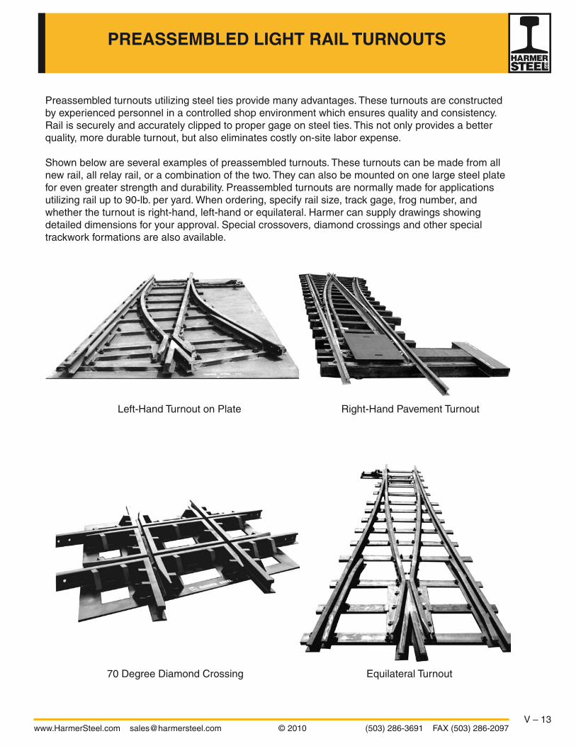
V – 13www.HarmerSteel.com [email protected] © 2010 (503) 286-3691 FAX (503) 286-2097
PREASSEMBLED LIGHT RAIL TURNOUTS
Preassembled turnouts utilizing steel ties provide many advantages. These turnouts are constructed by experienced personnel in a controlled shop environment which ensures quality and consistency. Rail is securely and accurately clipped to proper gage on steel ties. This not only provides a better quality, more durable turnout, but also eliminates costly on-site labor expense.
Shown below are several examples of preassembled turnouts. These turnouts can be made from all new rail, all relay rail, or a combination of the two. They can also be mounted on one large steel plate for even greater strength and durability. Preassembled turnouts are normally made for applications utilizing rail up to 90-lb. per yard. When ordering, specify rail size, track gage, frog number, and whether the turnout is right-hand, left-hand or equilateral. Harmer can supply drawings showing detailed dimensions for your approval. Special crossovers, diamond crossings and other special trackwork formations are also available.
Left-Hand Turnout on Plate
Equilateral Turnout70 Degree Diamond Crossing
Right-Hand Pavement Turnout

V – 14(503) 286-3691 FAX (503) 286-2097 © 2010 www.HarmerSteel.com [email protected]
Floating heel blocks perform the same function as standard heel blocks, but they do not bolt through the stock rail. This type of heel block assembly is very versatile because the same block can be used for switches of various lengths. The Single Hole Floating Heel Block Assembly shown at right consists of a block that bolts to the joint bars and fits up against the stock rail. A thimble is not normally used so the hole in the switch point does not need to be oversized. Another style of floating heel block is used for switches in continuously welded rail. This “cwr” style block bolts directly to the switch point rail with two bolts and no joint bars are required.
Design 990 Heel Joints are commonly used with narrow gage mining turnouts to prevent looseness at the heel of the switch point. Use of a pipe thimble permits the heel joint to be drawn up absolutely tight while at the same time allows the point to move freely. These heel joints are made of plain splice or angle bars only. A pipe thimble is welded to one bar, and the other bar is bent slightly. Normally three-hole bars are used when the switch is less than 5’, and four-hole bars are used for switches that are 5’ or longer.
Standard Heel Block Assemblies are used in many standard gage industrial switches. They hold the switch point firm at the heel, maintain proper spread, and keep closure rail and switch point in correct alignment. These assemblies consist of a block, bent-and-planed bar, outside bar, thimble and bolts. The block can be made of cast iron or steel, or of welded steel construction. The outside bar can be a “D-bar” strap or a standard joint bar. Square-head bolts are usually used with the D-bar and track bolts are used with the joint bar. A shoulder-bolt is sometimes used instead of the thimble and standard bolt.
Stock rail
Left hand point
Straight joint barwith thimble
Left hand point
Closure rail
Bent joint bar Track bolts withnut & lockwasher
Stock rail
Left hand point
Machine bolts withnut & lockwasher
Bent joint barwith thimble Closure rail
Outside “D” bar
HEEL JOINTS
Stock rail
Left hand point
Straight joint barwith thimble
Left hand point
Closure rail
Bent joint bar Track bolts withnut & lockwasher
Stock rail
Left hand point
Machine bolts withnut & lockwasher
Bent joint barwith thimble Closure rail
Outside “D” bar
6-1/4
SectionView

V – 15www.HarmerSteel.com [email protected] © 2010 (503) 286-3691 FAX (503) 286-2097
PLATES & BRACES
Rigid Brace & Brace PlateThe rigid brace is the most common brace for industrial switches. The brace plate is designed to fit a particular style brace and is often called a “combination plate,” “riser plate,” or “slide plate.” The riser of this plate can be formed in several ways. A pressed riser is formed by pushing up the steel under the riser area. A welded riser utilizes an additional steel shim which is welded to the plate. A milled riser is formed when a “pocket” or “seat” for the rail is milled out of the plate.
Adjustable Rail Brace & PlateAdjustable rail braces are used for heavy-duty and main line switches. They allow the brace to be installed and later adjusted without disturbing the stock rail or plate. Adjustable braces come in several different designs. Shown at right is a“2-bolt” AREMA type design.
Turnout Pocket PlateThis type of plate is used behind the heel of a switch in heavy-duty applications where it is preferred over twin tie plates. These plates are designed to fit a specific rail section, switch length, tie spacing, and turnout alignment. These plates can be milled right-hand, left-hand, or no-hand. The no-hand plates can be used in either a right orleft-hand turnout, but the right and left-hand plates are not interchangeable.

V – 16(503) 286-3691 FAX (503) 286-2097 © 2010 www.HarmerSteel.com [email protected]
Twin Tie Plates are used for frogs, guard rails, and behind the heel of switches. They are produced to standard AREMA designs and are very versatile. The slotted hole allows them to fit almost any rail section. Their use in pairs, side by side on the same tie, allows them to adapt to different tie spacings, frog angles, etc. The standard AREMA thickness is 3/4”, but a 5/8” thickness is common for industrial trackwork. Two typical applications are shown below.
#1
#2
#1
#2
#1#2
#1
#2
#1
#2#1
#2
#1
#2
#1
#2#1
#1
#1
#1
#1
#1
#1#1
#1
#1
#1
#1
Note: Square Spike Holes (or Hooks) Must Always be on Outside of Rail
Application of Twin Tie Plates No. 1 & No. 2 Behind the Heel of a Switch
Application of Twin Tie Plates No. 1 & No. 2 on Bolted Rigid FrogNote: Twin Tie Plate No. 2 (or Type LR) to be used on Heel of Frog only
Where it is Possible to Spike Between Rails
Switch Point
Switch Point
TWIN TIE PLATES

V – 17www.HarmerSteel.com [email protected] © 2010 (503) 286-3691 FAX (503) 286-2097
Hook Twin Tie Plates are manufactured per AREMA plan 241. Hook twin tie plates generally come with three types of hooks: Low – Type L, Low Reverse – Type LR, and High – Type H. Type H plates do not have the slotted hole and have a higher hook designed to fit over the base of a manganese frog. If the hook of a hook twin tie plate interferes with a joint bar, the hook can be cut off or bent to a vertical position.
L
2” 4-7/8” 3” 1”
3/4”
1”3/4”
3/4”3/4”
3/4”
3/4”1”14°
3/4”
3/4”
3/4”
3/4”
4”
H
3/4”1”14°H
L
2” 4-7/8”2-1/8”1”
3/4”
1-3/8”
1-3/8”
4”
1”
Mark L and H
Mark LR
3/4”4”
4”
4”
3/4”
2’– 0-1/2”
2’– 0-1/2”
2’-6”
3/4”
2”4-3/4”2-1/2”
3/4”
2”4-3/4”2-1/2”
3/4”3/4”
3/4”
3/4”
3/4”3/4”
2”4-3/4” 1-3/4”
3/4”3/4”
Type 1
TWIN TIE PLATES
Hook Twin Tie Plates are manufactured per AREMA plan 241.
Mark L H Wt. (lbs.) L23 23” 9/16” 18.8 L27 27” 9/16” 22.2 L31 31” 9/16” 25.6 H23 23” 15/16” 19.1 H27 27” 15/16” 22.5 H31 31” 15/16” 25.9 LR23 23” 9/16” 18.8 LR27 27” 9/16” 22.2 LR31 31” 9/16” 25.6
Flat Twin Tie Plates aremanufactured as shown.
Weight (lbs.) Type 5/8” thick 3/4” thick No. 1 16.9 20.3 No. 2 16.9 20.3 No. 3 20.8 24.9
Type 2
3/4”4”
4”
4”
3/4”
2’– 0-1/2”
2’– 0-1/2”
2’-6”
3/4”
2”4-3/4”2-1/2”
3/4”
2”4-3/4”2-1/2”
3/4”3/4”
3/4”
3/4”
3/4”3/4”
2”4-3/4” 1-3/4”
3/4”3/4”
Type 3
3/4”4”
4”
4”
3/4”
2’– 0-1/2”
2’– 0-1/2”
2’-6”
3/4”
2”4-3/4”2-1/2”
3/4”
2”4-3/4”2-1/2”
3/4”3/4”
3/4”
3/4”
3/4”3/4”
2”4-3/4” 1-3/4”
3/4”3/4”
Hook Twin Tie Plates
Flat Twin Tie Plates
L
2” 4-7/8” 3” 1”
3/4”
1”3/4”
3/4”3/4”
3/4”
3/4”1”14°
3/4”
3/4”
3/4”
3/4”
4”
H
3/4”1”14°H
L
2” 4-7/8”2-1/8”1”
3/4”
1-3/8”
1-3/8”
4”
1”

V – 18(503) 286-3691 FAX (503) 286-2097 © 2010 www.HarmerSteel.com [email protected]
SWITCH STANDS
Racor 22E
Racor 36EH
The Racor 22E and 22EH are extra-heavy-duty trailable switch stands. The low stand 22E is for yard, ladder and busy switch turnouts, where trains often run through switches. The 22EH is constructed of identical base housing and operating parts, but features a high mast and target, providing increased visibility where needed. The 22E and 22EH can be trailed or thrown manually. When a train runs through the switch, switch points are partially opened by the wheel flanges, and the throw is completed automatically. This eliminates expensive repairs to stand, track and derailed equipment that result when a train runs through a switch with a rigid stand.
The Racor 36E and 36EH are extra-heavy-duty non-trailable switch stands for unrestricted use. Both models have identical base housing and operating parts. The 36E is most often used for yard operations, while the 36EH, with high mast and target, is suitable for mainline use.
All switch stands shown on this page are supplied with an adjustable connecting rod and screw eye crank which permits accurate setting of the points without re-spiking the stand. They also come with the ergonomic “trihandle.” This triangular hand lever has a grasp point that is 30” above the ground, helping to prevent risky bending and lifting. The typical 180° movement of the lever has been reduced to 120°, so the switch can be thrown with minimal operator motion.
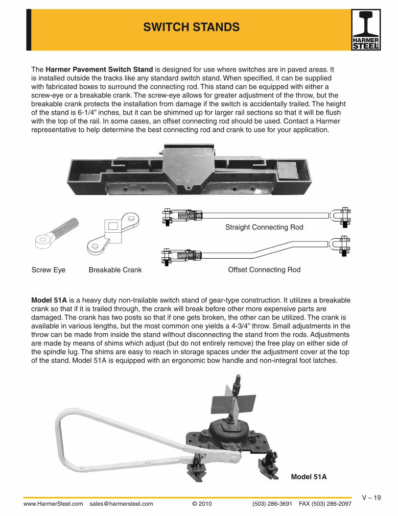
V – 19www.HarmerSteel.com [email protected] © 2010 (503) 286-3691 FAX (503) 286-2097
SWITCH STANDS
Model 51A
The Harmer Pavement Switch Stand is designed for use where switches are in paved areas. It is installed outside the tracks like any standard switch stand. When specified, it can be supplied with fabricated boxes to surround the connecting rod. This stand can be equipped with either a screw-eye or a breakable crank. The screw-eye allows for greater adjustment of the throw, but the breakable crank protects the installation from damage if the switch is accidentally trailed. The height of the stand is 6-1/4” inches, but it can be shimmed up for larger rail sections so that it will be flush with the top of the rail. In some cases, an offset connecting rod should be used. Contact a Harmer representative to help determine the best connecting rod and crank to use for your application.
Model 51A is a heavy duty non-trailable switch stand of gear-type construction. It utilizes a breakable crank so that if it is trailed through, the crank will break before other more expensive parts are damaged. The crank has two posts so that if one gets broken, the other can be utilized. The crank is available in various lengths, but the most common one yields a 4-3/4” throw. Small adjustments in the throw can be made from inside the stand without disconnecting the stand from the rods. Adjustments are made by means of shims which adjust (but do not entirely remove) the free play on either side of the spindle lug. The shims are easy to reach in storage spaces under the adjustment cover at the top of the stand. Model 51A is equipped with an ergonomic bow handle and non-integral foot latches.
Straight Connecting Rod
Offset Connecting RodBreakable CrankScrew Eye

V – 20(503) 286-3691 FAX (503) 286-2097 © 2010 www.HarmerSteel.com [email protected]
Connecting Rods
The length of all connecting rods shown below can be adjusted by means of a threaded clevis. The rigid rods have adjustable clevises on both ends. Spring connecting rods are recommended for any installation where there is a chance that switches will be trailed through. When a switch equipped with a spring connecting rod is trailed through, the spring allows the wheels to force the point over, and then pulls the points back to the original position after each set of wheels has passed. If a switch equipped with a rigid rod is trailed through, it is very likely the switch stand will be damaged and there is a greater chance of derailment. The spring connecting rods shown below are of direct-acting concentric design with all working parts fully enclosed. This provides a strong structure as well as giving protection from any foreign substances that might hinder operation.
Design 8 Spring Connecting RodWeight 16 lbs.Length 30”
Design 9 Spring Connecting RodWeight 35 lbs.Length 39”
Design 10 Rigid Connecting RodWeight 24 lbs.Length 41”
Design 8 Rigid Connecting Rod (not shown)Weight 7 lbs.Length 32”
SWITCH STANDS FOR LIGHT RAILS
Design 10 and 11 switch stands are parallel throw stands of the cam operated type. They are flat bottomed and very low profile. All moving parts are above the ties where they are readily accessible and free from dirt. The amount of the throw is easily adjustable by means of the screw-eye crank. These stands are normally supplied without a target, but can be furnished with target upon request. They are available with either a rigid or spring connecting rod.
Design 10 Switch Stand is intended for use with rails weighing up to 60 lbs per yard. It weighs 38 lbs and can be ordered with either Design 8 spring connecting rod or a Design 8 rigid connecting rod.
Design 11 Switch Stand is intended for use with rails weighing 60 lbs or more per yard. It is provided with locking ears so that the lever may be padlocked in either position. It weighs 70 lbs and can be ordered with either Design 9 spring connecting rod or Design 10 rigid connecting rod.

V – 21www.HarmerSteel.com [email protected] © 2010 (503) 286-3691 FAX (503) 286-2097
AMERICAN MINING CONGRESS TURNOUT DATA
Turnout Data for 18-in. Gage 20-lb to 60-lb ASCE rail, inclusive American Mining Congress Standards
Cast Frog Switch Closure Rails Design 269 Curved Straight
Switch Vertex Actual Frog No. Frog Angle Length Angle Distance Lead Radius MO Length Length
2-1/2 22°37’12” 3’6” 6°19’20” 4” 7’5-1/16” 11’10-1/8” 1-7/16” 3’4-11/16” 3’2-3/16”
3 18°55’29” 5’0” 4°25’15” 5” 9’11-1/2” 17’2-1/8” 1-11/16” 4’4-7/16” 4’2-3/8”
4 14°15’00” 5’0” 4°25’15” 5” 11’3-5/8” 31’6-5/8” 1-13/32” 5’5-1/8” 5’3-9/16”
5 11°25’16” 7’6” 2°56’44” 8” 15’8-1/8” 47’4-13/16” 1-9/16” 7’0-5/16” 6’11-1/16”
6 9°31’38” 10’0” 2°12’32” 10” 20’0” 67’1-3/16” 1-11/16” 8’7” 8’5-15/16”
Turnout Data for 24-in. Gage 20-lb to 60-lb ASCE rail, inclusive American Mining Congress Standards
Cast Frog Switch Closure Rails Design 289 Curved Straight Switch Vertex Actual Frog No. Frog Angle Length Angle Distance Lead Radius MO Length Length
2 28°04’21” 3’6” 6°19’20” 4” 8’3-5/8” 12’1-5/32” 2-17/32” 4’5-31/32” 4’2-3/16”
2-1/2 22°37’12” 5’0” 4°25’15” 5” 11’2-5/16” 18’2-9/32” 2-11/16” 5’8-3/16” 5’5-3/16”
3 18°55’29” 5’0” 4°25’15” 5” 12’3-1/4” 27’1-21/32” 2-1/2” 6’8-13/16” 6’6-5/16”
7’6” 2°56’44” 8” 15’3-1/2” 26’2-1/4” 3” 7’2-1/2” 6’11-7/8”
3-1/2 16°15’38” 5’0” 4°25’15” 5” 13’4-5/8” 37’2-1/2” 2-3/8” 7’8-1/4” 7’6-1/16”
7’6” 2°56’44” 8” 16’5-13/16” 35’7-7/16” 2-7/8” 8’3-3/8” 8’1-1/4”
4 14°15’00” 5’0” 4°25’15” 5” 14’2-13/16” 50’1-23/32” 2-1/8” 8’4-15/32” 8’2-1/2”
7’6” 2°56’44” 8” 17’5-7/8” 46’11-15/16” 2-21/32” 9’1-21/32” 8’11-9/16”
5 11°25’16” 7’6” 2°56’44” 8” 19’6-1/4” 75’0-13/16” 2-13/32” 10’10-15/32” 10’8-15/16”
10’0” 2°12’32” 10” 22’7-21/32” 72’5-15/16” 2-3/4” 11’5-13/16” 11’4-11/32”
6 9°31’38” 7’6” 2°56’44” 8” 21’4-7/8” 111’7-11/16” 2-1/8” 12’5-25/32” 12’4-9/16”
10’0” 2°12’32” 10” 24’8-9/16” 106’1” 2-17/32” 13’3-23/32” 13’2-1/4”
Turnout Data for 30-in. GageLight Rail – 20-lb to 60-lb ASCE rail, inclusive American Mining Congress Standards
Frog Switch Closure Rails
Actual
Rail Toe
Actual
Curved Straight
No. Angle Type
Weight
Length Length Angle
Lead
Radius MO Length Length
Cast 20 to 60 1/4” 6-11/16” 3’6” 6°19’20” 3/8” 5” 4” 9’5” 13’0” 3-7/8” 5’9-1/2” 5’4-1/4”
2 28°04’21” WPF 20 to 30 1/4” 17” 3’6” 6°19’20” 3/8” 5” 4” 9’5” 13’0” 2-13/16” 4’11” 4’6”
WPF 40 to 60 3/8” 20” 3’6” 6°19’20” 3/8” 5” 4” 9’5” 13’0” 2-1/2” 4’8-1/4” 4’3”
Cast 20 to 60 1/4” 8-1/4” 5’0” 4°25’15” 3/8” 5” 5” 12’10” 21’0” 4” 7’5-3/4” 7’1-3/4”
2-1/2 22°37’12” WPF 20 to 30 1/4” 16-1/2” 5’0” 4°25’15” 3/8” 5” 5” 12’10” 21’0” 3-5/16” 6’9-1/2” 6’5-1/2”
WPF 40 to 60 3/8” 20” 5’0” 4°25’15” 3/8” 5” 5” 12’10” 21’0” 3” 6’6” 6’2”
Cast 20 to 60 1/4” 8-3/8” 5’0” 4°25’15” 3/8” 5” 5” 14’4” 32’0” 3-3/4” 8’11” 8’7-1/2”
3 18°55’29” WPF 20 to 30 1/4” 16-1/2” 5’0” 4°25’15” 3/8” 5” 5” 14’4” 32’0” 3-3/16” 8’2-3/4” 7’11-1/2”
WPF 40 to 60 3/8” 24” 5’0” 4°25’15” 3/8” 5” 5” 14’4” 32’0” 2-3/4” 7’7-1/2” 7’4”
4 14°15’00” Cast 20 to 60 1/4” 11-1/16” 5’0” 4°25’15” 3/8” 5” 5” 17’0” 60’0” 3-1/8” 11’3-1/2” 11’1”
WPF 40 to 60 3/8” 27” 5’0” 4°25’15” 3/8” 5” 5” 17’0” 60’0” 2-7/16” 9’11-1/2” 9’9”
5 11°25’16” Cast 20 to 60 1/4” 13-13/16” 7’6” 2°56’44” 3/8” 5” 8” 23’0” 93’0” 3-3/8” 14’6-1/4” 14’4-1/4”
WPF 40 to 60 3/8” 30” 7’6” 2°56’44” 3/8” 5” 8” 23’0” 93’0” 2-13/16” 13’2” 13’0”
6 9°31’38” Cast 20 to 60 1/4” 16-9/16” 7’6” 2°56’44” 3/8” 5” 8” 25’7” 139’0” 3-1/16” 16’10” 16’8-1/2”
WPF 40 to 60 3/8” 36” 7’6” 2°56’44” 3/8” 5” 8” 25’7” 139’0” 2-1/2” 15’2-3/4” 15’1”
6 9°31’38”
Cast 20 to 60 1/4” 16-9/16” 10’0” 2°12’32” 3/8” 5” 10” 29’0” 133’0” 3-9/16” 17’9” 17’7-1/2”
WPF 40 to 60 3/8” 36” 10’0” 2°12’32” 3/8” 5” 10” 29’0” 133’0” 3” 16’1-3/4” 16’0”
Note: W.P.F. denotes “Welded Plate Frog.”
Ver
tex
Dis
tanc
e
Poi
nt
Poi
nt
Hee
lS
prea
d

V – 22(503) 286-3691 FAX (503) 286-2097 © 2010 www.HarmerSteel.com [email protected]
AMERICAN MINING CONGRESS TURNOUT DATA
Turnout Data for 36-in. GageLight Rail – 20-lb to 60-lb ASCE rail, inclusive American Mining Congress Standards
Frog Switch Closure Rails
Actual Rail Toe Actual
Curved Straight
No. Angle Type
Weight Length Length Angle
Lead Radius MO Length Length
Cast 20 to 60 1/4” 6-11/16” 3’6” 6°19’20” 3/8” 5” 4” 11’0” 17’0” 4-7/8” 7’5-1/2” 6’11-1/4”
2 28°04’21” WPF 20 to 30 1/4” 17” 3’6” 6°19’20” 3/8” 5” 4” 11’0” 17’0” 3-7/8” 6’7-1/4” 6’1”
WPF 40 to 60 3/8” 20” 3’6” 6°19’20” 3/8” 5” 4” 11’0” 17’0” 3-9/16” 6’4-1/4” 5’10”
Cast 20 to 40 1/4” 8-1/4” 5’0” 4°25’15” 3/8” 5” 5” 15’0” 28’0” 5-1/16” 9’8-1/2” 9’3-3/4”
2-1/2 22°37’12” WPF 20 to 30 1/4” 16-1/2” 5’0” 4°25’15” 3/8” 5” 5” 15’0” 28’0” 4-3/8” 9’0-1/4” 8’7-1/2”
WPF 40 to 60 3/8” 20” 5’0” 4°25’15” 3/8” 5” 5” 15’0” 28’0” 4-1/16” 8’8-3/4” 8’4”
Cast 20 to 60 1/4” 8-3/8” 5’0” 4°25’15” 3/8” 5” 5” 16’9” 42’0” 4-5/8” 11’4-3/4” 11’0-3/4”
3 18°55’29” WPF 20 to 30 1/4” 16-1/2” 5’0” 4°25’15” 3/8” 5” 5” 16’9” 42’0” 4-1/8” 10’8-1/2” 10’4-1/2”
WPF 40 to 60 3/8” 24” 5’0” 4°25’15” 3/8” 5” 5” 16’9” 42’0” 3-5/8” 10’1” 9’9”
4 14°15’00” Cast 20 to 60 1/4” 11-1/16” 5’0” 4°25’15” 3/8” 5” 5” 20’0” 78’0” 3-15/16” 14’4” 14’1”
WPF 40 to 60 3/8” 27” 5’0” 4°25’15” 3/8” 5” 5” 20’0” 78’0” 3-1/4” 13’0-1/4” 12’9”
5 11°25’16” Cast 20 to 60 1/4” 13-13/16” 7’6” 2°56’44” 3/8” 5” 8” 27’0” 120’0” 4-5/16” 18’6-3/4” 18’4-1/4”
WPF 40 to 60 3/8” 30” 7’6” 2°56’44” 3/8” 5” 8” 27’0” 120’0” 3-3/4” 17’2-1/2” 17’0”
6 9°31’38” Cast 20 to 60 1/4” 16-9/16” 7’6” 2°56’44” 3/8” 5” 8” 30’2” 179’0” 3-7/8” 21’5-1/2” 21’3-1/2”
WPF 40 to 60 3/8” 36” 7’6” 2°56’44” 3/8” 5” 8” 30’2” 179’0” 3-5/16” 19’10” 19’8”
6 9°31’38” Cast 20 to 60 1/4” 16-9/16” 10’0” 2°12’32” 3/8” 5” 10” 34’0” 171’0” 4-9/16” 22’9-1/2” 22’7-1/2”
WPF 40 to 60 3/8” 36” 10’0” 2°12’32” 3/8” 5” 10” 34’0” 171’0” 3-15/16” 21’2” 21’0”
Note: WPF denotes “Welded Plate Frog.”
Hee
lS
prea
d
Ver
tex
Dis
tanc
e
Poi
nt
Poi
nt
Turnout Data for 30-in. Gage (continued)Heavy Rail – 70-lb. to 80-lb. ASCE rail, inclusive American Mining Congress Standards
Frog Switch Closure Rails
Actual Rail Toe Actual
Curved Straight
No. Angle Type
Weight Length Length Angle
Lead Radius MO Length Length
3 18°55’29” Cast 70 to 80 1/2” 9-1/2” 7’6” 3°35’00” 3/8” 6” 6” 16’7” 30’0” 3-5/8” 8’ 6-3/4” 8’3-1/2”
RBF 70 to 80 1/2” 31” 7’6” 3°35’00” 3/8” 6” 6” 16’7” 30’0” 2-5/16” 6’9-1/4” 6’6”
4 14°15’00” Cast 70 to 80 1/2” 12-1/2” 7’6” 3°35’00” 3/8” 6” 6” 20’0” 55’0” 3-11/16” 11’7-15/16” 11’5-1/2”
RBF 70 to 80 1/2” 40” 7’6” 3°35’00” 3/8” 6” 6” 20’0” 55’0” 2-3/8” 9’4-7/16” 9’2”
5 11°25’16” Cast 70 to 80 1/2” 15-11/16” 10’0” 2°41’12” 3/8” 6” 8” 25’0” 87’0” 3-5/16” 13’10-1/4” 13’8-5/16”
RBF 70 to 80 1/2” 42-1/2” 10’0” 2°41’12” 3/8” 6” 8” 25’0” 87’0” 2-5/16” 11’7-9/16” 11’5-1/2”
6 9°31’38” Cast 70 to 80 1/2” 18-13/16” 10’0” 2°41’12” 3/8” 6” 8” 27’6” 130’0” 3” 16’0-7/8” 15’11-3/16”
RBF 70 to 80 1/2” 45” 10’0” 2°41’12” 3/8” 6” 8” 27’6” 130’0” 2-1/4” 13’10-3/4” 13’9”
Note: W.P.F. denotes “Welded Plate Frog.”
Hee
lS
prea
d
Ver
tex
Dis
tanc
e
Poi
nt
Poi
nt

V – 23www.HarmerSteel.com [email protected] © 2010 (503) 286-3691 FAX (503) 286-2097
AMERICAN MINING CONGRESS TURNOUT DATA
Turnout Data for 42-in. GageThe American Mining Congress has adopted 42-in. gage as the standard for mines. This gage should be used when it is possible to do so.
Light Rail – 20-lb to 60-lb ASCE rail, inclusive American Mining Congress Standards
Frog Switch Closure Rails
Actual Rail Toe Actual
Curved Straight
No. Angle Type
Weight Length Length Angle
Lead Radius MO Length Length
Cast 20 to 40 1/4” 6-11/16” 3’6” 6°19’20” 3/8” 5” 4” 12’7” 22’0” 5-5/8” 9’1-1/2” 8’6-1/4”
2 28°04’21” WPF 20 to 30 1/4” 17” 3’6” 6°19’20” 3/8” 5” 4” 12’7” 22’0” 4-3/4” 8’3-1/4” 7’8”
WPF 40 3/8” 20” 3’6” 6°19’20” 3/8” 5” 4” 12’7” 22’0” 4-1/2” 8’0-1/4” 7’5”
Cast 20 to 40 1/4” 8-1/4” 5’0” 4°25’15” 3/8” 5” 5” 16’11” 35’0” 5-13/16” 11’8-1/4” 11’2-3/4”
2-1/2 22°37’12” WPF 20 to 30 1/4” 16-1/2” 5’0” 4°25’15” 3/8” 5” 5” 16’11” 35’0” 5-1/4” 10’11-7/8” 10’6-1/2”
WPF 40 3/8” 20” 5’0” 4°25’15” 3/8” 5” 5” 16’11” 35’0” 4-7/8” 10’8-1/2” 10’3”
Cast 20 to 60 1/4” 8-3/8” 5’0” 4°25’15” 3/8” 5” 5” 19’0” 52’0” 5-1/2” 13’8-1/2” 13’3-1/2”
3 18°55’29” WPF 20 to 30 1/4” 16-1/2” 5’0” 4°25’15” 3/8” 5” 5” 19’0” 52’0” 5” 13’0-1/4” 12’7-1/2”
WPF 40 to 60 3/8” 24” 5’0” 4°25’15” 3/8” 5” 5” 19’0” 52’0” 4-11/16” 12’5” 12’0”
Cast 20 to 60 1/4” 8-3/8” 6’0” 3°40’59” 3/8” 5” 6” 20’6” 51’0” 5-7/8” 14’2-3/4” 13’9-1/2”
3 18°55’29” WPF 20 to 30 1/4” 16-1/2” 6’0” 3°40’59” 3/8” 5” 6” 20’6” 51’0” 5-3/8” 13’6” 13’1-1/2”
WPF 40 to 60 3/8” 24” 6’0” 3°40’59” 3/8” 5” 6” 20’6” 51’0” 4-7/8” 12’10-3/4” 12’6”
4 14°15’00” Cast 20 to 60 1/4” 11-1/16” 5’0” 4°25’15” 3/8” 5” 5” 23’0” 96’0” 4-5/8” 17’4-1/2” 17’1”
WPF 40 to 60 3/8” 27” 5’0” 4°25’15” 3/8” 5” 5” 23’0” 96’0” 4-1/16” 16’0-3/4” 15’9”
4 14°15’00” Cast 40 to 60 1/4” 11-1/16” 6’0” 3°40’59” 3/8” 5” 6” 24’7” 94’0” 5-1/8” 17’11-1/4” 17’7-3/4”
WPF 40 to 60 3/8” 27” 6’0” 3°40’59” 3/8” 5” 6” 24’7” 94’0” 4-7/16” 16’7-1/2” 16’4”
4 14°15’00” Cast 40 to 60 1/4” 11-1/16” 7’6” 2°56’44” 3/8” 5” 8” 26’10” 91’0” 5-3/4” 18’8-1/4” 18’4-3/4”
WPF 40 to 60 3/8” 27” 7’6” 2°56’44” 3/8” 5” 8” 26’10” 91’0” 5” 17’4-1/2” 17’1”
5 11°25’16” Cast 40 to 60 1/4” 13-13/16” 7’6” 2°56’44” 3/8” 5” 8” 31’0” 148’0” 5-3/16” 22’7” 22’4-1/4”
WPF 40 to 60 3/8” 30” 7’6” 2°56’44” 3/8” 5” 8” 31’0” 148’0” 4-11/16” 21’2-3/4” 21’0”
6 9°31’38” Cast 40 to 60 1/4” 16-9/16” 7’6” 2°56’44” 3/8” 5” 8” 34’9” 220’0” 4-5/8” 26’0-3/4” 25’10-1/2”
WPF 40 to 60 3/8” 36” 7’6” 2°56’44” 3/8” 5” 8” 34’9” 220’0” 4-1/8” 24’5-1/2” 24’3”
6 9°31’38” Cast 40 to 60 1/4” 16-9/16” 10’0” 2°12’32” 3/8” 5” 10” 38’10” 210’0” 5-7/16” 27’7-3/4” 27’5-1/2”
WPF 40 to 60 3/8” 36” 10’0” 2°12’32” 3/8” 5” 10” 38’10” 210’0” 4-3/4” 26’0-1/4” 25’10”
Note: WPF denotes “Welded Plate Frog.”
Hee
lS
prea
d
Ver
tex
Dis
tanc
e
Poi
nt
Poi
nt
Turnout Data for 36-in. Gage (continued)Heavy Rail – 70-lb to 100-lb rail, inclusive American Mining Congress Standards
Frog Switch Closure Rails
Actual Rail Toe Actual
Curved Straight
No. Angle Type
Weight Length Length Angle
Lead Radius MO Length Length
Cast 70 to 80 1/2” 9-1/2” 7’6” 3°35’00” 3/8” 6” 6” 19’1” 39’0” 4-3/4” 11’1-7/16” 10’9-1/2”
3 18°55’29” Cast 85 to 100 1/2” 11” 7’6” 3°44’35” 3/8” 6-1/4” 6” 18’10-5/8” 37’7-3/16” 4-5/8” 10’9-9/16” 10’5-5/8”
RBF 70 to 80 1/2” 31” 7’6” 3°35’00” 3/8” 6” 6” 19’1” 39’0” 3-3/8” 9’3-15/16” 9’ 0”
RBF 85 to 100 1/2” 31” 7’6” 3°44’35” 3/8” 6-1/4” 6” 18’10-5/8” 37’7-3/16” 3-3/8” 9’1-9/16” 8’9-5/8”
Cast 70 to 80 1/2” 12-9/16” 7’6” 3°35’00” 3/8” 6” 6” 22’5” 73’0” 4-1/8” 14’1-1/2” 13’10-1/2”
4 14°15’00” Cast 85 to 100 1/2” 14-5/8” 7’6” 3°44’35” 3/8” 6-1/4” 6” 22’2-1/2” 70’4-5/8” 4” 13’8-7/8” 13’5-7/8”
RBF 70 to 80 1/2” 40” 7’6” 3°35’00” 3/8” 6” 6” 22’5” 73’0” 2-7/8” 11’10” 11’7”
RBF 85 to 100 1/2” 40” 7’6” 3°44’35” 3/8” 6-1/4” 6” 22’2-1/2” 70’4-5/8” 2-7/8” 11’7-1/2” 11’ 4-1/2”
Cast 70 to 80 1/2” 15-11/16” 10’0” 2°41’12” 3/8” 6” 8” 29’0” 114’ 0” 4-1/4” 17’10-11/16” 17’8-5/16”
5 11°25’16” Cast 85 to 100 1/2” 18-3/16” 10’0” 2°48’23” 3/8” 6-1/4” 8” 28’9-1/8” 110’6” 4-1/8” 17’5-3/8” 17’2-15/16”
RBF 70 to 80 1/2” 42-1/2” 10’0” 2°41’12” 3/8” 6” 8” 29’0” 114’0” 3-1/4” 15’7-7/8” 15’5-1/2”
RBF 85 to 100 1/2” 42-1/2” 10’0” 2°48’23” 3/8” 6-1/4” 8” 28’9-1/8” 110’6” 3-1/4” 15’5-1/16” 15’2-5/8”
Cast 70 to 80 1/2” 18-13/16” 10’0” 2°41’12” 3/8” 6” 8” 32’2” 169’0” 3-13/16” 20’9-3/16” 20’7-3/16”
6 9°31’38” Cast 85 to 100 1/2” 21-13/16” 10’0” 2°48’23” 3/8” 6-1/4” 8” 31’10-1/2” 165’ 4-3/16” 3-3/4” 20’2-3/4” 20’0-11/16”
RBF 70 to 80 1/2” 45” 10’0” 2°41’12” 3/8” 6” 8” 32’2” 169’0” 3-1/16” 18’7-1/16” 18’5”
RBF 85 to 100 1/2” 45” 10’0” 2°48’23” 3/8” 6-1/4” 8” 31’10-1/2” 165’4-3/16” 3-1/16” 18’3-9/16” 18’1-1/2”
Cast 70 to 80 1/2” 21-15/16” 10’0” 2°41’12” 3/8” 6” 8” 35’4-11/16” 238’11-11/16” 3-9/16” 23’8-1/2” 23’6-3/4”
7 8°10’16” Cast 85 to 100 1/2” 25-7/16” 10’0” 2°48’23” 3/8” 6-1/4” 8” 34’9-3/8” 234’7-15/16” 3-5/16” 22’9-11/16” 22’7-15/16”
RBF 70 to 80 1/2” 56-1/2” 10’0” 2°41’12” 3/8” 6” 8” 35’4-11/16” 238’11-11/16” 2-3/4” 20’9-15/16” 20’8-3/16”
RBF 85 to 100 1/2” 56-1/2” 10’0” 2°48’23” 3/8” 6-1/4” 8” 34’9-3/8” 234’7-15/16” 2-5/8” 20’2-5/8” 20’0-7/8”
Cast 70 to 80 1/2” 25-1/16” 15’0” 1°47’27” 3/8” 6” 12” 45’8-7/8” 298’8-11/16” 4-3/16” 28’9-1/2” 28’7-13/16”
8 7°09’10” Cast 85 to 100 1/2” 29-1/16” 15’0” 1°52’14” 3/8” 6-1/4” 12” 45’0-3/8” 291’9-1/4” 3-15/16” 27’8-13/16” 27’7-5/16”
RBF 70 to 80 1/2” 61” 15’0” 1°47’27” 3/8” 6” 12” 45’8-7/8” 298’8-11/16” 3-3/8” 25’9-11/16” 25’7-7/8”
RBF 85 to 100 1/2” 61” 15’0” 1°52’14” 3/8” 6-1/4” 12” 45’0-3/8” 291’9-1/4” 3-1/4” 25’0-7/8” 24’11-3/8”
Note: RBF denotes “Rigid Bolted Frog.”
Hee
lS
prea
d
Ver
tex
Dis
tanc
e
Poi
nt
Poi
nt

V – 24(503) 286-3691 FAX (503) 286-2097 © 2010 www.HarmerSteel.com [email protected]
AMERICAN MINING CONGRESS TURNOUT DATA
Turnout Data for 44-in. GageLight Rail – 20-lb to 60-lb ASCE rail, inclusive American Mining Congress Standards
Frog Switch Closure Rails
Actual Rail Toe Actual
Curved Straight No. Angle Type
Weight Length Length Angle
Lead Radius MO Length Length
Cast 20 to 60 1/4” 6-11/16” 3’6” 6°19’20” 3/8” 5” 4” 13’2” 24’0” 5-15/16” 9’8-3/4” 9’1-1/4”
2 28°04’21” WPF 20 to 30 1/4” 17” 3’6” 6°19’20” 3/8” 5” 4” 13’2” 24’0” 4-15/16” 8’10-1/2” 8’3”
WPF 40 to 60 3/8” 20” 3’6” 6°19’20” 3/8” 5” 4” 13’2” 24’0” 4-5/8” 8’7-1/2” 8’0”
Cast 20 to 60 1/4” 8-1/4” 5’0” 4°25’15” 3/8” 5” 5” 17’7” 37’0” 6-3/16” 12’4-1/2” 11’10-3/4”
2-1/2 22°37’12” WPF 20 to 30 1/4” 16-1/2” 5’0” 4°25’15” 3/8” 5” 5” 17’7” 37’0” 5-9/16” 11’8-1/4” 11’2-1/2”
WPF 40 to 60 3/8” 20” 5’0” 4°25’15” 3/8” 5” 5” 17’7” 37’0” 5-1/4” 11’4-3/4” 10’11”
Cast 20 to 60 1/4” 8-3/8” 5’0” 4°25’15” 3/8” 5” 5” 19’11” 55’0” 5-13/16” 14’7-1/4” 14’2-1/2”
3 18°55’29” WPF 20 to 30 1/4” 16-1/2” 5’0” 4°25’15” 3/8” 5” 5” 19’11” 55’0” 5-5/16” 13’11-1/4” 13’6-1/2”
WPF 40 to 60 3/8” 24” 5’0” 4°25’15” 3/8” 5” 5” 19’11” 55’0” 4-7/8” 13’4” 12’11”
4 14°15’00” Cast 20 to 60 1/4” 11-1/16” 5’0” 4°25’15” 3/8” 5” 5” 24’0” 102’0” 4-15/16” 18’4-3/4” 18’0-3/4”
WPF 40 to 60 3/8” 27” 5’0” 4°25’15” 3/8” 5” 5” 24’0” 102’0” 4-5/16” 17’0-3/4” 16’9”
4 14°15’00” Cast 20 to 60 1/4” 11-1/16” 6’0” 3°40’49” 3/8” 5” 6” 25’8” 99’0” 5-1/2” 19’0-1/2” 18’8-3/4”
WPF 40 to 60 3/8” 27” 6’0” 3°40’49” 3/8” 5” 6” 25’8” 99’0” 5-1/16” 18’3” 17’4-1/2”
4 14°15’00” Cast 20 to 60 1/4” 11-1/16” 7’6” 2°56’44” 3/8” 5” 8” 28’0” 97’0” 6-1/8” 19’10-1/4” 19’6-3/4”
WPF 40 to 60 3/8” 27” 7’6” 2°56’44” 3/8” 5” 8” 28’0” 97’0” 5-5/16” 18’6-3/4” 18’3”
5 11°25’16” Cast 20 to 60 1/4” 13-13/16” 7’6” 2°56’44” 3/8” 5” 8” 32’3” 156’0” 5-7/16” 23’10” 23’7”
WPF 40 to 60 3/8” 30” 7’6” 2°56’44” 3/8” 5” 8” 32’3” 156’0” 4-7/8” 22’6” 22’3”
6 9°31’38” Cast 20 to 60 1/4” 16-9/16” 7’6” 2°56’44” 3/8” 5” 8” 36’3” 233’0” 4-7/8” 27’6-3/4” 27’4-1/4”
WPF 40 to 60 3/8” 36” 7’6” 2°56’44” 3/8” 5” 8” 36’3” 233’0” 4-5/16” 25’11-1/2” 25’9”
6 9°31’38” Cast 20 to 60 1/4” 16-9/16” 10’0” 2°12’32” 3/8” 5” 10” 40’5” 223’0” 5-3/4” 29’2-1/2” 29’0-1/4”
WPF 40 to 60 3/8” 36” 10’0” 2°12’32” 3/8” 5” 10” 40’5” 223’0” 5-1/8” 27’7-1/2” 27’5”
Note: W.P.F. denotes “Welded Plate Frog.”
Hee
lS
prea
d
Ver
tex
Dis
tanc
e
Poi
nt
Poi
nt
Turnout Data for 42-in. Gage (continued)Heavy Rail – 70-lb to 100-lb rail, inclusive American Mining Congress Standards
Frog Switch Closure Rails
Actual
Rail Toe
Heel Actual
Curved Straight
No. Angle Type
Weight
Length Length
Angle
Lead Radius MO Length Length
Cast 70 to 80 1/2” 9-1/2” 7’6” 3°35’00” 3/8” 6” 6” 21’7” 49’0” 5-3/4” 13’8-1/16” 13’3-1/2”
3 18°55’29” Cast 85 to 100 1/2” 11” 7’6” 3°44’35” 3/8” 6-1/4” 6” 21’4-9/16” 47’2-3/4” 5-5/8” 13’4-3/16” 12’11-9/16”
RBF 70 to 80 1/2” 31” 7’6” 3°35’00” 3/8” 6” 6” 21’7” 49’0” 4-5/16” 11’10-9/16” 11’6”
RBF 85 to 100 1/2” 31” 7’6” 3°44’35” 3/8” 6-1/4” 6” 21’4-9/16” 47’2-3/4” 4-5/16” 11’8-3/16” 11’3-9/16”
Cast 70 to 80 1/2” 12-9/16” 7’6” 3°35’00” 3/8” 6” 6” 25’7” 90’0” 5” 17’4” 17’0-1/2”
4 14°15”00” Cast 85 to 100 1/2” 14-5/8” 7’6” 3°44’35” 3/8” 6-1/4” 6” 25’4-3/8” 87’10-3/16” 4-7/8” 16’11-5/16” 16’7-3/4”
RBF 70 to 80 1/2” 40” 7’6” 3°35’00” 3/8” 6” 6” 25’7” 90’0” 3-3/4” 15’0-1/2” 14’9”
RBF 85 to 100 1/2” 40” 7’6” 3°44’35” 3/8” 6-1/4” 6” 25’4-3/8” 87’ 10-3/16” 3-3/4” 14’9-15/16” 14’6-3/8”
Cast 70 to 80 1/2” 15-11/16” 10’0” 2°41’12” 3/8” 6” 8” 33’1” 140’0” 5-3/16” 22’0-1/16” 21’9-5/16”
5 11°25’16” Cast 85 to 100 1/2” 18-3/16” 10’0” 2°48’23” 3/8” 6-1/4” 8” 32’9-1/4” 137’4-9/16” 5” 21’5-7/8” 21’3-1/16”
RBF 70 to 80 1/2” 42-1/2” 10’0” 2°41’12” 3/8” 6” 8” 33’1” 140’0” 4-3/16” 19’9-1/4” 19’6-1/2”
RBF 85 to 100 1/2” 42-1/2” 10’0” 2°48’23” 3/8” 6-1/4” 8” 32’9-1/4” 137’4-9/16” 4-1/8” 19’5-9/16” 19’2-3/4”
Cast 70 to 80 1/2” 18-13/16” 10’0” 2°41’12” 3/8” 6” 8” 36’10” 209’0” 4-5/8” 25’5-9/16” 25’3-3/16”
6 9°31’38” Cast 85 to 100 1/2” 21-13/16” 10’0” 2°48’23” 3/8” 6-1/4” 8” 36’6” 205’0-3/4” 4-1/2” 24’10-5/8” 24’8-3/16”
RBF 70 to 80 1/2” 45” 10’0” 2°41’12” 3/8” 6” 8” 36’10” 209’0” 3-7/8” 23’3-3/8” 23’1”
RBF 85 to 100 1/2” 45” 10’0” 2°48’23” 3/8” 6-1/4” 8” 36’6” 205’0-3/4” 3-7/8” 22’11-7/16” 22’9”
Cast 70 to 80 1/2” 21-15/16” 10’0” 2°41’12” 3/8” 6” 8” 40’7-13/16” 294’1-3/4” 4-5/16” 28’11-7/8” 28’9-7/8”
7 8°10’16” Cast 85 to 100 1/2” 25-7/16” 10’0” 2°48’23” 3/8” 6-1/4” 8” 39’11-3/4” 290’6-1/8” 4-1/16” 28’0-7/16” 27’10-5/16”
RBF 70 to 80 1/2” 56-1/2” 10’0” 2°41’12” 3/8” 6” 8” 40’7-13/16” 294’1-3/4” 3-1/2” 26’1-5/16” 25’11-5/16”
RBF 85 to 100 1/2” 56-1/2” 10’0” 2°48’23” 3/8” 6-1/4” 8” 39’11-3/4” 290’6-1/8” 3-3/8” 25’5-3/8” 25’3-1/4”
Cast 70 to 80 1/2” 25-1/16” 15’0” 1°47’27” 3/8” 6” 12” 52’1-5/8” 367’3-3/4” 5-1/16” 35’2-1/2” 35’0-9/16”
8 7°9’10” Cast 85 to 100 1/2” 29-1/16” 15’0” 1°52’14” 3/8” 6-1/4” 12” 51’4-7/16” 360’8-7/8” 4-13/16” 34’1-1/8” 33’11-3/8”
RBF 70 to 80 1/2” 61” 15’0” 1°47’27” 3/8” 6” 12” 52’1-5/8” 367’3-3/4” 4-1/4” 32’2-9/16” 32’0-5/8”
RBF 85 to 100 1/2” 61” 15’0” 1°52’14” 3/8” 6-1/4” 12” 51’4-7/16” 360’8-7/8” 4-1/8” 31’5-3/16” 31’3-7/16”
Note: RBF denotes “Rigid Bolted Frog.”
Ver
tex
Dis
tanc
e
Poi
nt
Poi
nt
Hee
lS
prea
d

V – 25www.HarmerSteel.com [email protected] © 2010 (503) 286-3691 FAX (503) 286-2097
AMERICAN MINING CONGRESS TURNOUT DATA
Turnout Data for 48-in. GageLight Rail – 20-lb to 60-lb ASCE rail, inclusive American Mining Congress Standards
Frog Switch Closure Rails
Actual Rail Toe Actual
Curved Straight
No. Angle Type
Weight Length Length Angle
Lead Radius MO Length Length
Cast 20 to 60 1/4” 6-11/16” 3’6” 6°19’20” 3/8” 5” 4” 14’3” 26’0” 6-3/4” 10’10-1/4” 10’2-1/4”
2 28°04’21” WPF 20 to 30 1/4” 17” 3’6” 6°19’20” 3/8” 5” 4” 14’3” 26’0” 5-3/4” 10’0-1/4” 9’4”
WPF 40 to 60 3/8” 20” 3’6” 6°19’20” 3/8” 5” 4” 14’3” 26’0” 5-1/2” 9’9-1/4” 9’1”
Cast 20 to 60 1/4” 8-1/4” 5’0” 4°25’15” 3/8” 5” 5” 19’0” 41’0” 7” 13’10-1/4” 13’3-3/4”
2-1/2 22°37’12” WPF 20 to 30 1/4” 16-1/2” 5’0” 4°25’15” 3/8” 5” 5” 19’0” 41’0” 6-5/16” 13’2” 12’7-1/2”
WPF 40 to 60 3/8” 20” 5’0” 4°25’15” 3/8” 5” 5” 19’0” 41’0” 6-1/16” 12’10-1/2” 12’4”
Cast 20 to 60 1/4” 8-3/8” 5’0” 4°25’15” 3/8” 5” 5” 21’7” 62’0” 6-7/16” 16’4” 15’10-1/2”
3 18°55’29” WPF 20 to 30 1/4” 16-1/2” 5’0” 4°25’15” 3/8” 5” 5” 21’7” 62’0” 5-15/16” 15’8” 15’2-1/2”
WPF 40 to 60 3/8” 24” 5’0” 4°25’15” 3/8” 5” 5” 21’7” 62’0” 5-1/2” 15’0-1/2” 14’7”
4 14°15’00” Cast 20 to 60 1/4” 11-1/16” 5’0” 4°25’15” 3/8” 5” 5” 26’0” 114’0” 5-1/2” 20’5” 20’1”
WPF 40 to 60 3/8” 27” 5’0” 4°25’15” 3/8” 5” 5” 26’0” 114’0” 4-13/16” 19’1-1/4” 18’9”
4 14°15’00” Cast 20 to 60 1/4” 11-1/16” 7’6” 2°56’44” 3/8” 5” 8” 30’2” 108’0” 6-3/4” 22’0-1/2” 21’8-3/4”
WPF 40 to 60 3/8” 27” 7’6” 2°56’44” 3/8” 5” 8” 30’2” 108’0” 6-5/16” 20’9” 20’5”
5 11°25’16” Cast 20 to 60 1/4” 13-13/16” 7’6” 2°56’44” 3/8” 5” 8” 35’0” 174’0” 6-1/16” 26’7-1/2” 26’4-1/4”
WPF 40 to 60 3/8” 30” 7’6” 2°56’44” 3/8” 5” 8” 35’0” 174’0” 5-1/2” 25’3-1/4” 25’0”
6 9°31’38” Cast 20 to 60 1/4” 16-9/16” 7’6” 2°56’44” 3/8” 5” 8” 39’4” 260’0” 5-7/16” 30’8-1/4” 30’5-1/2”
WPF 40 to 60 3/8” 36” 7’6” 2°56’44” 3/8” 5” 8” 39’4” 260’0” 4-7/8” 29’0-3/4” 28’10”
6 9°31’38” Cast 20 to 60 1/4” 16-9/16” 10’0” 2°12’32” 3/8” 5” 10” 43’8” 248’0” 6-7/8” 32’6-1/4” 32’3-1/2”
WPF 40 to 60 3/8” 36” 10’0” 2°12’32” 3/8” 5” 10” 43’8” 248’0” 5-3/4” 30’10-3/4” 30’8”
Note: WPF denotes “Welded Plate Frog.”
Hee
lS
prea
d
Ver
tex
Dis
tanc
e
Poi
nt
Poi
nt
Turnout Data for 44-in. Gage (continued)Heavy Rail – 70-lb to 100-lb rail, inclusive American Mining Congress Standards
Frog Switch Closure Rails
Actual Rail Toe Actual
Curved Straight
No. Angle Type
Weight Length Length Angle
Lead Radius MO Length Length
Cast 70 to 80 1/2” 9-1/2” 7’6” 3°35’00” 3/8” 6” 6” 22’6” 52’0” 6-1/8” 14’7-1/4” 14’2-1/2”
3 18°55’29” Cast 85 to 100 1/2” 11” 7’6” 3°44’35” 3/8” 6-1/4” 6” 22’2-9/16” 50’5-5/16” 5-15/16” 14’2-3/8” 13’9-9/16”
RBF 70 to 80 1/2” 31” 7’6” 3°35’00” 3/8” 6” 6” 22’6” 52’0” 4-3/4” 12’10” 12’5”
RBF 85 to 100 1/2” 31” 7’6” 3°44’35” 3/8” 6-1/4” 6” 22’2-9/16” 50’5-5/16” 4-11/16” 12’6-3/8” 12’1-9/16”
Cast 70 to 80 1/2” 12-9/16” 7’6” 3°35’00” 3/8” 6” 6” 26’10” 96’0” 5-3/8” 18’7” 18’3-1/2”
4 14°15’00” Cast 85 to 100 1/2” 14-5/8” 7’6” 3°44’35” 3/8” 6-1/4” 6” 26’5” 93’8-1/16” 5-3/16” 18’0-1/8” 17’8-3/8”
RBF 70 to 80 1/2” 40” 7’6” 3°35’00” 3/8” 6” 6” 26’10” 96’0” 4-3/16” 16’3-3/4” 16’0”
RBF 85 to 100 1/2” 40” 7’6” 3°44’35” 3/8” 6-1/4” 6” 26’5” 93’8-1/16” 4-1/16” 15’10-3/4” 15’7”
Cast 70 to 80 1/2” 15-11/16” 10’0” 2°41’12” 3/8” 6” 8” 34’7” 149’0” 5-9/16” 23’6” 23’3-1/4”
5 11°25’16” Cast 85 to 100 1/2” 18-3/16” 10’0” 2°48’23” 3/8” 6-1/4” 8” 34’1-1/4” 146’4-1/16” 5-5/16” 22’10-1/16” 22’7-1/16”
RBF 70 to 80 1/2” 42-1/2” 10’0” 2°41’12” 3/8” 6” 8” 34’7” 149’0” 4-9/16” 21’3-1/2” 21’0-1/2”
RBF 85 to 100 1/2” 42-1/2” 10’0” 2°48’23” 3/8” 6-1/4” 8” 34’1-1/4” 146’ 4-1/16” 4-7/16” 20’9-3/4” 20’6-3/4”
Cast 70 to 80 1/2” 18-13/16” 10’0” 2°41’12” 3/8” 6” 8” 38’8” 222’0” 5-1/16” 27’3-1/2” 27’1”
6 9°31’38” Cast 85 to 100 1/2” 21-13/16” 10’0” 2°48’23” 3/8” 6-1/4” 8” 38’0-1/2” 218’3-5/8” 4-13/16” 26’5-5/16” 26’2-11/16”
RBF 70 to 80 1/2” 45” 10’0” 2°41’12” 3/8” 6” 8” 38’8” 222’0” 4-1/4” 25’1-1/2” 24’11”
RBF 85 to 100 1/2” 45” 10’0” 2°48’23” 3/8” 6-1/4” 8” 38’0-1/2” 218’3-5/8” 4-1/8” 24’6-1/8” 24’3-1/2”
Cast 70 to 80 1/2” 21-15/16” 10’0” 2°41’12” 3/8” 6” 8” 42’4-7/8” 312’7-7/16” 4-9/16” 30’9-1/8” 30’6-15/16”
7 8°10’16” Cast 85 to 100 1/2” 25-7/16” 10’0” 2°48’23” 3/8” 6-1/4” 8” 41’8-5/8” 309’1-1/2” 4-5/16” 29’9-5/16” 29’7-3/16”
RBF 70 to 80 1/2” 56-1/2” 10’0” 2°41’12” 3/8” 6” 8” 42’4-7/8” 312’7-7/16” 3-3/4” 27’10-9/16” 27’8-3/8”
RBF 85 to 100 1/2” 56-1/2” 10’0” 2°48’23” 3/8” 6-1/4” 8” 41’8-5/8” 309’1-1/2” 3-5/8” 27’ 2-1/4” 27’0-1/8”
Cast 70 to 80 1/2” 25-1/16” 15’0” 1°47’27” 3/8” 6” 12” 54’3-3/16” 390’2-1/16” 5-3/8” 37’4-3/16” 37’2-1/8”
8 7°9’10” Cast 85 to 100 1/2” 29-1/16” 15’0” 1°52’14” 3/8” 6-1/4” 12” 53’5-3/4” 383’8-11/16” 5-1/8” 36’2-9/16” 36’0-11/16”
RBF 70 to 80 1/2” 61” 15’0” 1°47’27” 3/8” 6” 12” 54’3-3/16” 390’2-1/16” 4-1/2” 34’4-1/4” 34’2-3/16”
RBF 85 to 100 1/2” 61” 15’0” 1°52’14” 3/8” 6-1/4” 12” 53’5-3/4” 383’8-11/16” 4-7/16” 33’6-5/8” 33’4-3/4”
Note: R.B.F. denotes “Rigid Bolted Frog.”
Ver
tex
Dis
tanc
e
Poi
nt
Poi
nt
Hee
lS
prea
d

V – 26(503) 286-3691 FAX (503) 286-2097 © 2010 www.HarmerSteel.com [email protected]
AMERICAN MINING CONGRESS TURNOUT DATA
Turnout Data for 56-1/2-in. GageLight Rail – 20-lb to 60-lb ASCE rail, inclusive American Mining Congress Standards
Frog Switch Closure Rails
Actual Rail Toe Actual
Curved Straight No. Angle Type
Weight Length Length Angle Point
Lead Radius MO Length Length
Cast 20 to 60 1/4” 6-11/16” 3’6” 6°19’20” 3/8” 5” 4” 16’7” 33’0” 8-1/16” 13’4” 12’6-1/4”
2 28°04’21” WPF 20 to 30 1/4” 17” 3’6” 6°19’20” 3/8” 5” 4” 16’7” 33’0” 7-1/16” 12’5-3/4” 11’8”
WPF 40 to 60 3/8” 20” 3’6” 6°19’20” 3/8” 5” 4” 16’7” 33’0” 6-3/4” 12’2-3/4” 11’5”
Cast 20 to 60 1/4” 8-1/4” 5’0” 4°25’15” 3/8” 5” 5” 22’0” 51’0” 8-7/16” 16’11-1/4” 16’3-3/4”
2-1/2 22°37’12” WPF 20 to 30 1/4” 16-1/2” 5’0” 4°25’15” 3/8” 5” 5” 22’0” 51’0” 7-3/4” 16’3” 15’7-1/2”
WPF 40 to 60 3/8” 20” 5’0” 4°25’15” 3/8” 5” 5” 22’0” 51’0” 7-1/2” 15’11-1/2” 15’4”
Cast 20 to 60 1/4” 8-3/8” 5’0” 4°25’15” 3/8” 5” 5” 25’0” 76’0” 7-3/4” 19’10” 19’3-1/2”
3 18°55’29” WPF 20 to 30 1/4” 16-1/2” 5’0” 4°25’15” 3/8” 5” 5” 25’0” 76’0” 7-1/4” 19’1-3/4” 18’7-1/2”
WPF 40 to 60 3/8” 24” 5’0” 4°25’15” 3/8” 5” 5” 25’0” 76’0” 6-3/4” 18’6-1/2” 18’0”
4 00°15’00” Cast 00 to 00 1/4” 11-1/16” 5’0” 4°25’15” 3/8” 5” 5” 30’4” 140’0” 6-9/16” 24’9-3/4” 24’5”
WPF 00 to 00 3/8” 27” 5’0” 4°25’15” 3/8” 5” 5” 30’4” 140’0” 5-15/16” 23’6” 23’1”
4 14°15’00” Cast 20 to 60 1/4” 11-1/16” 7’6” 2°56’44” 3/8” 5” 8” 34’10” 132’0” 8-3/16” 26’9-1/2” 26’4-3/4”
WPF 40 to 60 3/8” 27” 7’6” 2°56’44” 3/8” 5” 8” 34’10” 132’0” 7-11/16” 25’6” 25’1-1/4”
5 11°25’16” Cast 20 to 60 1/4” 13-13/16” 7’6” 2°56’44” 3/8” 5” 8” 40’7” 212’0” 7-3/8” 32’3” 31’11-1/4”
WPF 40 to 60 3/8” 30” 7’6” 2°56’44” 3/8” 5” 8” 40’7” 212’0” 6-3/4” 30’10-3/4” 30’7”
6 9°31’38” Cast 20 to 60 1/4” 16-9/16” 7’6” 2°56’44” 3/8” 5” 8” 45’10” 316’0” 6-9-16” 37’2-3/4” 36’11-1/2”
WPF 40 to 60 3/8” 36” 7’6” 2°56’44” 3/8” 5” 8” 45’10” 316’0” 6” 35’7-1/4” 35’4”
6 9°31’38” Cast 20 to 60 1/4” 16-9/16” 10’0” 2°12’32” 3/8” 5” 10” 50’7” 302’0” 7-3/4” 39’5-1/2” 39’2-1/2”
WPF 40 to 60 3/8” 36” 10’0” 2°12’32” 3/8” 5” 10” 50’7” 302’0” 7-1/8” 37’10-1/4” 37’7”
Note: WPF denotes “Welded Plate Frog.”
Hee
lS
prea
d
Ver
tex
Dis
tanc
e
Poi
nt
Turnout Data for 48-in. Gage (continued)Heavy Rail – 70-lb to 100-lb rail, inclusive American Mining Congress Standards
Frog Switch Closure Rails
Actual
Rail Toe Actual
Curved Straight No. Angle Type
Weight
Length Length Angle
Lead Radius MO Length Length
Cast 70 to 80 1/2” 9-1/2” 7’6” 3°35’00” 3/8” 6” 6” 24’1” 58’0” 6-13/16” 16’2-13/16” 15’9-1/2”
3 18°55’29” Cast 85 to 100 1/2” 11” 7’6” 3°44’35” 3/8” 6-1/4” 6” 23’10-1/2” 56’10-5/16” 6-11/16” 15’10-13/16” 15’5-1/2”
RBF 70 to 80 1/2” 31” 7’6” 3°35’00” 3/8” 6” 6” 24’1” 58’0” 5-3/8” 14’5-1/4” 14’0”
RBF 85 to 100 1/2” 31” 7’6” 3°44’35” 3/8” 6-1/4” 6” 23’10-1/2” 56’10-5/16” 5-3/8” 14’2-13/16” 13’9-1/2”
Cast 70 to 80 1/2” 12-9/16” 7’6” 3°35’00” 3/8” 6” 6” 28’10” 107’0” 5-15/16” 20’7-9/16” 20’3-1/2”
4 14°15’00” Cast 85 to 100 1/2” 14-5/8” 7’6” 3°44’35” 3/8” 6-1/4” 6” 28’6-1/4” 105’3-3/4” 5-3/4” 20’1-3/4” 19’9-5/8”
RBF 70 to 80 1/2” 40” 7’6” 3°35’00” 3/8” 6” 6” 28’10” 107’0” 4-3/4” 18’4-1/16” 18’0”
RBF 85 to 100 1/2” 40” 7’6” 3°44’35” 3/8” 6-1/4” 6” 28’6-1/4” 105’3-3/4” 4-5/8” 18’0-3/8” 17’8-1/4”
Cast 70 to 80 1/2” 15-11/16” 10’0” 2°41’12” 3/8” 6” 8” 37’1” 167’0” 6-1/8” 26’0-1/2” 25’9-5/16”
5 11°25’16” Cast 85 to 100 1/2” 18-3/16” 10’0” 2°48’23” 3/8” 6-1/4” 8” 36’9-5/16” 164’3-1/8” 5-15/16” 25’6-3/8” 25’3-1/8”
RBF 70 to 80 1/2” 42-1/2” 10’0” 2°41’12” 3/8” 6” 8” 37’1” 167’0” 5-1/16” 23’9-3/4” 23’6-1/2”
RBF 85 to 100 1/2” 42-1/2” 10’0” 2°48’23” 3/8” 6-1/4” 8” 36’9-5/16” 164’3-1/8” 5-1/16” 23’6-1/16” 23’2-3/16”
Cast 70 to 80 1/2” 18-13/16” 10’0” 2°41’12” 3/8” 6” 8” 41’6” 248’0” 5-1/2” 30’1-15/16” 29’11-3/16”
6 9°31’38” Cast 85 to 100 1/2” 21-13/16” 10’0” 2°48’23” 3/8” 6-1/4” 8” 41’1-1/2” 244’9-5/16” 5-3/8” 29’6-9/16” 29’3-11/16”
RBF 70 to 80 1/2” 45” 10’0” 2°41’12” 3/8” 6” 8” 41’6” 248’0” 4-3/4” 27’11-3/4” 27’ 9”
RBF 85 to 100 1/2” 45” 10’0” 2°48’23” 3/8” 6-1/4” 8” 41’1-1/2” 244’9-5/16” 4-11/16” 27’7-3/8” 27’4-1/2”
Cast 70 to 80 1/2” 21-13/16” 10’0” 2°41’12” 3/8” 6” 8” 45’10-15/16” 349’4-7/16” 5-1/16” 34’3-5/16” 34’1”
7 8°10’16” Cast 85 to 100 1/2” 25-7/16” 10’0” 2°48’23” 3/8” 6-1/4” 8” 45’2-1/4” 346’4-1/4” 4-13/16” 33’3-3/16” 33’0-13/16”
RBF 70 to 80 1/2” 56-1/2” 10’0” 2°41’12” 3/8” 6” 8” 45’10-15/16” 349’4-7/16” 4-1/4” 31’4-3/4” 31’2-7/16”
RBF 85 to 100 1/2” 56-1/2” 10’0” 2°48’23” 3/8” 6-1/4” 8” 45’2-1/4” 346’4-1/4” 4-1/16” 30’8-1/8” 30’ 5-3/4”
Cast 70 to 80 1/2” 25-1/16” 15’0” 1°47’27” 3/8” 6” 12” 58’6-5/16” 435’10-3/4” 5-5/8” 41’7-1/2” 41’5-1/4”
8 7°9’10” Cast 85 to 100 1/2” 29-1/16” 15’0” 1°52’14” 3/8” 6-1/4” 12” 57’8-7/16” 429’8-7/16” 5-3/4” 40’5-3/8” 40’3-3/8”
RBF 70 to 80 1/2” 61” 15’0” 1°47’27” 3/8” 6” 12” 58’6-5/16” 435’10-3/4” 5-1/16” 38’7-9/16” 38’5-5/16”
RBF 85 to 100 1/2” 61” 15’0” 1°52’14” 3/8” 6-1/4” 12” 57’8-7/16” 429’8-7/16” 5” 37’9-7/16” 37’7-7/16”
Note: RBF denotes “Rigid Bolted Frog.”
Ver
tex
Dis
tanc
e
Poi
nt
Poi
nt
Hee
lS
prea
d

V – 27www.HarmerSteel.com [email protected] © 2010 (503) 286-3691 FAX (503) 286-2097
AMERICAN MINING CONGRESS TURNOUT DATA
Data For Turnouts With Long SwitchesLight Rail – 20-lb to 60-lb ASCE rail, inclusive. With Cast Frogs American Mining Congress Standards
Switch Actual
Closure Rails Frog
Gage Vertex Lead Curved Straight No.
Length Distance Radius MO Length Length
36” 6’0” 6” 18’0” 41’0” 4-15/16” 11’7-1/2” 11’3-1/2” 42” 6’0” 6” 20’6” 51’0” 5-15/16” 14’2-3/4” 13’9-1/2” 3 44” 6’0” 6” 21’4” 54’0” 6-1/4” 15’0-1/4” 14’7-1/2” 48” 6’0” 6” 23’0” 60’0” 7” 16’8-3/4” 16’3-1/2” 56-1/2” 6’0” 6” 26’6” 74’0” 8-3/8” 20’3-3/4” 19’9-1/2” 36” 7’6” 8” 19’10” 40’0” 5-3/8” 11’11-1/4” 11’7-1/2” 42” 7’6” 8” 22’5” 50’0” 6-7/16” 14’7” 14’2-1/2” 3 44” 7’6” 8” 23’4” 53’0” 6-13/16” 15’6-1/4” 15’1-1/2” 48” 7’6” 8” 25’0” 59’0” 7-9/16” 17’2-3/4” 16’9-1/2” 56-1/2” 7’6” 8” 28’8” 73’0” 9” 20’11-1/2” 20’5-1/2” 36” 6’0” 6” 21’5” 76’0” 4-5/16” 14’8-3/4” 14’5-3/4” 42” 6’0” 6” 24’7” 94’0” 5-1/8” 17’11-1/4” 17’7-3/4” 4 44” 6’0” 6” 25’8” 99’0” 5-1/2” 19’0-1/2” 18’8-3/4” 48” 6’0” 6” 27’10” 111’0” 6-1/8” 21’2-3/4” 20’10-3/4” 56-1/2” 6’0” 6” 32’3” 136’0” 7-5/16” 25’8-1/2” 25’3-3/4” 36” 7’6” 8” 23’7” 74’0” 4-13/16” 15’4-1/2” 15’1-3/4” 42” 7’6” 8” 26’10” 91’0” 5-3/4” 18’8-1/4” 18’4-3/4” 4 44” 7’6” 8” 28’0” 97’0” 6-1/8” 19’10-1/4” 19’6-3/4” 48” 7’6” 8” 30’2” 108’0” 6-3/4” 22’0-1/2” 21’8-3/4” 56-1/2” 7’6” 8” 34’10” 132’0” 8-3/16” 26’9-1/2” 26’4-3/4” 36” 10’0” 10” 30’5” 116’0” 4-7/8” 19’5-1/4” 19’3” 42” 10’0” 10” 34’8” 143’0” 5-15/16” 23’8-3/4” 23’6” 5 44” 10’0” 10” 36’0” 151’0” 6-1/4” 25’0-3/4” 24’10” 48” 10’0” 10” 38’10” 169’0” 6-15/16” 27’11” 27’8” 56-1/2” 10’0” 10” 44’9” 206’0” 8-3/8” 33’10-3/4” 33’7”
Turnout Data for 56-1/2-in. Gage (continued)Heavy Rail – 70-lb to 100-lb rail, inclusive American Mining Congress Standards
Frog Switch Closure Rails
Actual Rail Toe Actual
Curved Straight No. Angle Type
Weight Length Angle
Lead Radius MO Length Length
Cast 70 to 80 1/2” 9-1/2” 7’6” 3°35’00” 3/8” 6” 6” 27’8” 72’0” 8-1/4” 19’10-3/4” 19’4-1/2” 3 18°55’29” Cast 85 to 100 1/2” 11” 7’6” 3°44’35” 3/8” 6-1/4” 6” 27’4-15/16” 70’6-1/16” 8-1/16” 19’6-3/16” 18’11-15/16” RBF 70 to 80 1/2” 31” 7’6” 3°35’00” 3/8” 6” 6” 27’8” 72’0” 6-13/16” 18’1-1/4” 17’7” RBF 85 to 100 1/2” 31” 7’6” 3°44’35” 3/8” 6-1/4” 6” 27’4-15/16” 70’6-1/16” 6-3/4” 17’10-3/16” 17’3-15/16” Cast 70 to 80 1/2” 12-9/16” 7’6” 3°35’00” 3/8” 6” 6” 33’4” 132’0” 7-3/16” 25’2-5/16” 24’9-1/2” 4 14°15’00” Cast 85 to 100 1/2” 14-5/8” 7’6” 3°44’35” 3/8” 6-1/4” 6” 32’11-15/16” 130’0-5/8” 7” 24’8-3/16” 24’3-5/16” RBF 70 to 80 1/2” 40” 7’6” 3°35’00” 3/8” 6” 6” 33’4” 132’0” 5-15/16” 22’10-13/16” 22’6” RBF 75 to 100 1/2” 40” 7’6” 3°44’35” 3/8” 6-1/4” 6” 32’11-15/16” 130’0-5/8” 5-7/8” 22’6-13/16” 22’1-15/16” Cast 70 to 80 1/2” 15-11/16” 10’0” 2°41’12” 3/8” 6” 8” 42’10” 205’0” 7-7/16” 31’10-1/16” 31’6-5/16” 5 11°25’16” Cast 85 to 100 1/2” 18-3/16” 10’0” 2°48’23” 3/8” 6-1/4” 8” 42’5-7/16” 202 4-1/8” 7-1/4” 31’3-1/16” 30’11-1/4” RBF 70 to 80 1/2” 42-1/2” 10’0” 2°41’12” 3/8” 6” 8” 42’10” 205’0” 6-7/16” 29’7-1/4” 29’3-1/2” RBF 85 to 100 1/2” 42-1/2” 10’0” 2°48’23” 3/8” 6-1/4” 8” 42’5-7/16” 202’4-1/8” 6-3/8” 29’2-3/4” 28’10-15/16” Cast 70 to 80 1/2” 18-13/16” 10’0” 2°41’12” 3/8” 6” 8” 48’2” 304’0” 6-3/4” 36’10-7/16” 36’7-3/16” 6 9°31’38” Cast 85 to 100 1/2” 21-13/16” 10’0” 2°48’23” 3/8” 6-1/4” 8” 47’8-3/16” 301’0-1/2” 6-1/2” 36’1-3/4” 35’10-3/8” RBF 70 to 80 1/2” 45” 10’0” 2°41’12” 3/8” 6” 8” 48’2” 304’0” 5-15/16” 34’8-1/4” 34’5”
RBF 85 to 100 1/2” 45” 10’0” 2°48’23” 3/8” 6-1/4” 8” 47’8-3/16” 301’0-1/2” 5-13/16” 34’2-9/16” 33’11-3/16” Cast 70 to 80 1/2” 21-15/16” 10’0” 2°41’12” 3/8” 6” 8” 53’4-7/16” 427’7-1/4” 6-1/8” 41’9-3/16” 41’6-1/2”
7 8°10’16” Cast 85 to 100 1/2” 25-7/16” 10’0” 2°48’23” 3/8” 6-1/4” 8” 52’6-11/16” 425’5-11/16” 5-7/8” 40’8-1/16” 40’5-1/4” RBF 70 to 80 1/2” 56-1/2” 10’0” 2°41’12” 3/8” 6” 8” 53’4-7/16” 427’7-1/4” 5-9/16” 38’10-5/8” 38’7-15/16” RBF 85 to 100 1/2” 56-1/2” 10’0” 2°48’23” 3/8” 6-1/4” 8” 52’6-11/16” 425’5-11/16” 5-1/8” 38’1” 37’10-3/16” Cast 70 to 80 1/2” 25-1/16” 15’0” 1°47’27” 3/8” 6” 12” 67’7” 533’0-3/4” 7-1/4” 50’8-5/8” 50’5-15/16” 8 7°9’10” Cast 85 to 100 1/2” 29-1/16” 15’0” 1°52’14” 3/8” 6-1/4” 12” 66’8-3/16” 527’4-7/8” 7” 49’5-1/2” 49’3-1/8” RBF 70 to 80 1/2” 61” 15’0” 1°47’27” 3/8” 6” 12” 67’7” 533’0-3/4” 6-7/16” 47’8-11/16” 47’6” RBF 85 to 100 1/2” 61” 15’0” 1°52’14” 3/8” 6-1/4” 12” 66’8-3/16” 527’4-7/8” 6-1/4” 46’9-9/16” 46’7-3/16”
Note: RBF denotes “Rigid Bolted Frog.”
Ver
tex
Dis
tanc
e
Poi
nt
Leng
th
Poi
nt
Hee
lS
prea
d

V – 28(503) 286-3691 FAX (503) 286-2097 © 2010 www.HarmerSteel.com [email protected]
AMERICAN MINING CONGRESS TURNOUT DATA
Data For Turnouts With Long Switches (continued)Heavy Rail – 70-lb to 100-lb rail, inclusive. With Cast Frogs American Mining Congress Standards
Switch Rail Actual
Closure Rails Frog Gage Vertex Weight Lead Curved Straight No.
Length
Distance Radius MO Length Length
36” 10’0” 10” 70 to 80 25’9-3/8” 70’1-1/16” 4-13/16” 14’11-3/4” 14’8-7/8”
10’0” 10” 85 to 100 25’5-1/16” 68’1-13/16” 4-5/8” 14’5-3/8” 14’2-7/16”
42” 10’0” 10” 70 to 80 29’1-11/16” 86’11-5/16” 5-7/8” 18’4-9/16” 18’1-3/16”
10’0” 10” 85 to 100 28’9-1/16” 85’0-3/4” 5-5/8” 17’9-7/8” 17’6-7/16”
4 44” 10’0” 10” 70 to 80 30’3-1/8” 92’6-11/16” 6-3/16” 19’3-3/16” 19’2-5/8”
10’0” 10” 85 to 100 29’10-7/16” 90’8-3/8” 6” 18’11-3/8” 18’7-13/16”
48” 10’0” 10” 70 to 80 32’6” 103’9-1/2” 6-7/8” 21’9-3/8” 21’5-1/2”
10’0” 10” 85 to 100 32’1-1/16” 101’11-5/8” 6-5/8” 21’2-7/16” 20’10-7/16”
56-1/2” 10’0” 10” 70 to 80 37’3-1/16” 127’8” 8-5/16” 26’7-3/16” 26’2-9/16”
10’0” 10” 85 to 100 36’9-3/4” 125’11-1/8” 8-1/16” 25’11-13/16” 25’7-1/8”
36” 15’0” 12” 70 to 80 35’4-9/16” 109’7-13/16” 5-1/8” 19’3-3/16” 19’0-7/8”
15’0” 12” 85 to 100 34’11-1/4” 106’7-15/16” 4-7/8” 18’7-3/8” 18’5-1/16”
42” 15’0” 12” 70 to 80 39’8-3/8” 135’6-9/16” 6-3/16” 23’7-7/16” 23’4-11/16”
15’0” 12” 85 to 100 39’2-3/4” 132’7-5/16” 6” 22’11-5/16” 22’8-9/16”
5 44” 15’0” 12” 70 to 80 41’1-5/8” 144’2-1/8” 6-9/16” 25’0-13/16” 24’9-15/16”
15’0” 12” 85 to 100 40’7-15/16” 141’3-1/8” 6-5/16” 24’4-9/16” 24’1-3/4”
48” 15’0” 12” 70 to 80 44’0-3/16” 161’5-1/4” 7-5/16” 27’11-5/8” 27’8-1/2”
15’0” 12” 85 to 100 43’6-1/4” 158’6-3/4” 7-1/16” 27’3-3/16” 27’0-1/16”
56-1/2” 15’0” 12” 70 to 80 50’1-9/16” 198’1-7/16” 8-7/8” 34’1-5/8” 33’9-7/8”
15’0” 12” 85 to 100 49’7-3/16” 195’3-7/8” 8-9/16” 33’4-11/16” 33’1”
36” 15’0” 12” 70 to 80 39’0-1/16” 161’2-7/16” 4-13/16” 22’7-1/4” 22’5-1/4”
15’0” 12” 85 to 100 38’5-11/16” 156’11-15/16” 4-9/16” 21’9-13/16” 21’7-7/8”
42” 15’0” 12” 70 to 80 44’0-5/8” 198’9-5/8” 5-13/16” 27’8-1/8” 27’5-13/16”
15’0” 12” 85 to 100 43’5-13/16” 194’8-7/16” 5-9/16” 26’10-1/4” 26’8”
6 44” 15’0” 12” 70 to 80 45’8-3/4” 211’4” 6-1/8” 29’4-7/16” 29’1-15/16”
15’0” 12” 85 to 100 45’1-7/8” 207’3-5/16” 5-15/16” 28’6-7/16” 28’4-1/16”
48” 15’0” 12” 70 to 80 49’1-1/8” 236’4-3/4” 6-13/16” 32’9-1/16” 32’6-5/16”
15’0” 12” 85 to 100 48’5-15/16” 232’4-15/16” 6-5/8” 31’10-3/4” 31’8-1/8”
56-1/2” 15’0” 12” 70 to 80 56’2-15/16” 289’7-13/16” 8-5/16” 39’11-3/8” 39’8-1/8”
15’0” 12” 85 to 100 55’7-1/8” 285’10” 8” 39’0-3/8” 38’9-5/16”
36” 15’0” 12” 70 to 80 42’5-7/16” 223’10-1/16” 4-1/2” 25’9-1/8” 25’7-1/2”
15’0” 12” 85 to 100 41’10” 218’5-1/4” 4-1/4” 24’10-1/4” 24’8-9/16”
42” 15’0” 12” 70 to 80 48’2-1/4” 275’6-15/16” 5-7/16” 31’6-1/4” 31’4-5/16”
15’0” 12” 85 to 100 47’6-5/16” 270’5-1/16” 5-3/16” 30’6-7/8” 30’4-7/8”
7 44” 15’0” 12” 70 to 80 50’1-3/16” 292’9-7/8” 5-3/4” 33’5-5/16” 33’3-1/4”
15’0” 12” 85 to 100 49’5-1/16” 287’9-1/16” 5-1/2” 32’5-3/4” 32’3-5/8”
48” 15’0” 12” 70 to 80 53’11-1/16” 327’3-13/16” 6-3/8” 37 3-7/16” 37’1-1/8”
15’0” 12” 85 to 100 53’2-5/8” 322’4-15/16” 6-3/16” 36’3-1/2” 36’1-3/16”
56-1/2” 15’0” 12” 70 to 80 62’0-5/8” 400’7-3/8” 7-3/4” 45’5-3/8” 45’2-11/16”
15’0” 12” 85 to 100 61’3-3/8” 396’0-11/16” 7-1/2” 44’4-11/16” 44’1-15/16”