hardware user manual - kipkipnews.kip.com/_public/800series/800_userguide.pdf · thank you for...
TRANSCRIPT

KIP 800 | Color Series
Hardware User Manual Version A.2a

(1)
Thank you for purchasing the KIP 800 Series. This Hardware Operation Guide contains functional and operational explanations for the KIP 800 Series. Please read this Hardware Operation Guide carefully before using the Printer. Please keep this Hardware Operation Guide for future reference. 1. When this product is installed in North America. This product complies with part 15 of the FCC Rules. Operation is subject to the following two conditions: (1) This product may not cause harmful interference, and (2) this device must accept any interference received, including interference that may cause undesired operation.
FCC CAUTION Changes or modifications not expressly approved by the party responsible for compliance could
void the user’s authority to operate the product.
Note: This product has been tested and found to comply with the limits for a Class A digital equipment, pursuant to part 15 of the FCC Rules. These limits are designed to provide reasonable protection against harmful interference when the product is operated in a commercial environment. This product generates, uses, and can radiate radio frequency energy and, if not installed and used in accordance with the instruction manual,, may cause harmful interference to radio communications. Operation of this product in a residential area is likely to cause harmful interference in which case the user will be required to correct the interference at his own expense.
This product complies with Part 15 of FCC Rules and Industry Canada licence-exempt RSS standard(s). Operation is subject to the following two conditions: (1) this product may not cause interference, and (2) this product must accept any interference, including interference that may cause undesired operation of this product.
Le présent appareil est conforme aux la partie 15 des règles de la FCC et CNR d’Industrie Canada applicables aux appareils radio exempts de licence. L’exploitation est autorisée aux deux conditions suivantes : (1) I’appareil ne doit pas produire de brouillage, et (2) I’utilisateur de I’appareil doit accepter tout brouillage radioélectrique subi, même si le brouillage est susceptible d’en comprometter le fonctionnement.
Contains FCC ID: VP8-13551 Contains IC: 7391A-13551 2. When this product is installed in Europe This product complies with the requirements in CISPR 32 for a Class A computing equipment. Operation of this product in a residential area may cause unacceptable interference to radio and TV reception requiring the operator to take whatever steps are necessary to correct the interference. Do not install product around other electronic equipment or other precision instruments. Other equipment may be effected by electrical noise during operation. If the product is installed near other electronic equipment, such as a TV or a radio, interference to said equipment, such as noise or flickering, may occur. Use a separate power line and install the PRINTER as far as possible from said equipment.
(2)
The International ENERGY STAR ® Office Equipment Program is an international program that promotes energy saving through the penetration of energy efficient computers and other office equipment. The program backs the development and dissemination of products with functions that effectively reduce energy consumption. It is an open system in which business proprietors can participate voluntarily. The targeted products are office equipment such as computers, monitors, printers, facsimiles, copiers, scanners, and multifunction devices. Their standards and logos are uniform among participating nations. Das Gerät ist nicht für die Benutzung am Bildschirmarbeitsplatz gemäß BildscharbV vorgesehen.
KIP 800 Series is an ENERGY STAR qualified multifunction device.
The symbol shown indicates that this product conforms to SJ/T11364-2006 of People’s Republic of China Electronic Industry Standard and does not apply to countries outside of People’s Republic of China. The symbol shown indicates that this product conforms to GB 18455-2001, SJ/T 11364-2006 of National Standard of the People’s Republic of China and does not apply to countries outside of People’s Republic of China.
The symbol shown indicates that this product conforms to Directive 2012/19/EC of the European Parliament and the council of 4 July 2012 on waste electrical and electronic equipment (WEEE) and does not apply to countries outside of EU.

(3)
The following warnings are very important in order to safely use this product. These notes are important in preventing danger to the operator or operation of the printer. The following symbols are found throughout the USER’S Manual and have the following meaning:
CAUTION This CAUTION mark means that there is a possibility of injury or physical damage if you ignore or do not follow the said instruction.
When marked with this symbol, “DO NOT ATTEMPT”.
When marked with this symbol, “pay close attention to”.
Safety Warning
WARNING This WARNING mark means that there is a possibility of death or serious injury if you ignore or do not follow the said instruction.
There are extremely hot parts inside. Do not touch any parts, or you will be burnt.
(4)
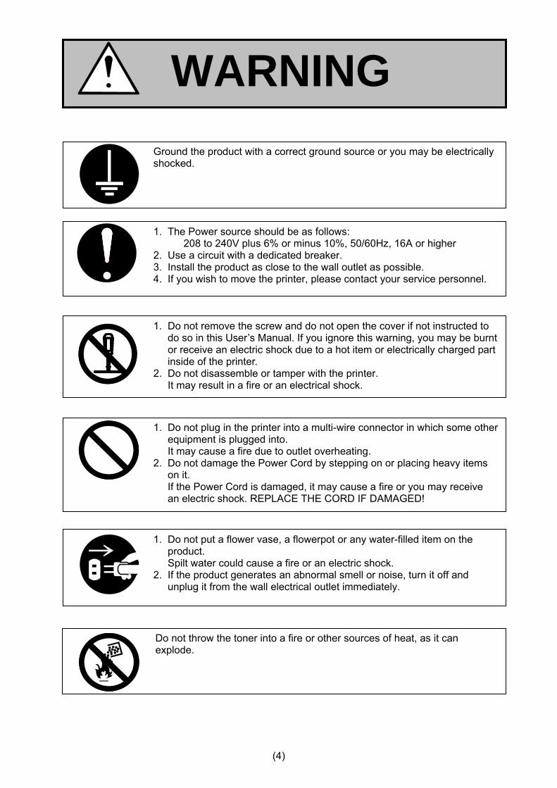
WARNING
1. The Power source should be as follows: 208 to 240V plus 6% or minus 10%, 50/60Hz, 16A or higher
2. Use a circuit with a dedicated breaker. 3. Install the product as close to the wall outlet as possible. 4. If you wish to move the printer, please contact your service personnel.
Ground the product with a correct ground source or you may be electrically shocked.
1. Do not plug in the printer into a multi-wire connector in which some other equipment is plugged into. It may cause a fire due to outlet overheating. 2. Do not damage the Power Cord by stepping on or placing heavy items on it. If the Power Cord is damaged, it may cause a fire or you may receive an electric shock. REPLACE THE CORD IF DAMAGED!
1. Do not put a flower vase, a flowerpot or any water-filled item on the product. Spilt water could cause a fire or an electric shock. 2. If the product generates an abnormal smell or noise, turn it off and unplug it from the wall electrical outlet immediately.
1. Do not remove the screw and do not open the cover if not instructed to do so in this User’s Manual. If you ignore this warning, you may be burnt or receive an electric shock due to a hot item or electrically charged part inside of the printer. 2. Do not disassemble or tamper with the printer. It may result in a fire or an electrical shock.
Do not throw the toner into a fire or other sources of heat, as it can explode.
(5)
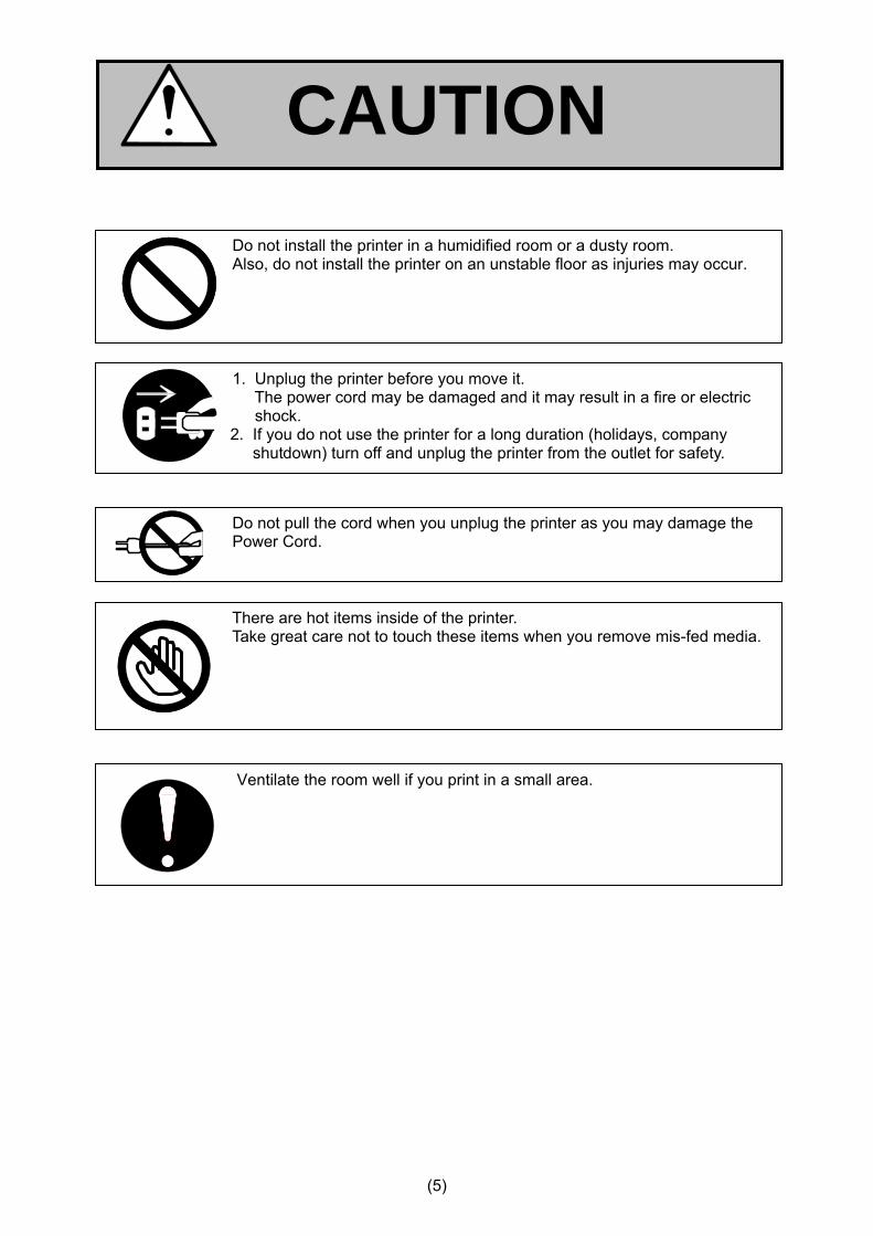
CAUTION
There are hot items inside of the printer. Take great care not to touch these items when you remove mis-fed media.
Do not pull the cord when you unplug the printer as you may damage the Power Cord.
Do not install the printer in a humidified room or a dusty room. Also, do not install the printer on an unstable floor as injuries may occur.
1. Unplug the printer before you move it. The power cord may be damaged and it may result in a fire or electric shock.
2. If you do not use the printer for a long duration (holidays, company shutdown) turn off and unplug the printer from the outlet for safety.
Ventilate the room well if you print in a small area.
(6)
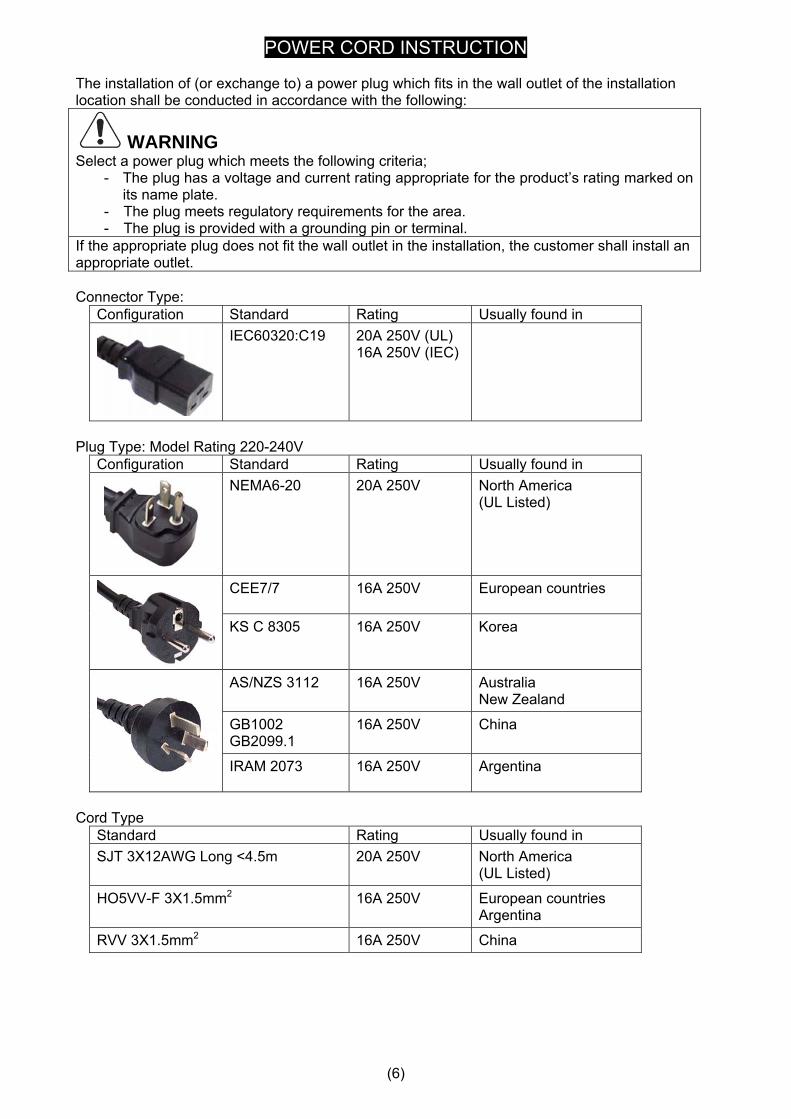
POWER CORD INSTRUCTION The installation of (or exchange to) a power plug which fits in the wall outlet of the installation location shall be conducted in accordance with the following:
WARNING Select a power plug which meets the following criteria;
- The plug has a voltage and current rating appropriate for the product’s rating marked on its name plate.
- The plug meets regulatory requirements for the area. - The plug is provided with a grounding pin or terminal.
If the appropriate plug does not fit the wall outlet in the installation, the customer shall install an appropriate outlet. Connector Type:
Configuration Standard Rating Usually found in
IEC60320:C19 20A 250V (UL) 16A 250V (IEC)
Plug Type: Model Rating 220-240V
Configuration Standard Rating Usually found in
NEMA6-20 20A 250V North America (UL Listed)
CEE7/7 16A 250V European countries
KS C 8305 16A 250V Korea
AS/NZS 3112 16A 250V Australia New Zealand
GB1002 GB2099.1
16A 250V China
IRAM 2073 16A 250V Argentina
Cord Type
Standard Rating Usually found in SJT 3X12AWG Long <4.5m 20A 250V North America
(UL Listed)
HO5VV-F 3X1.5mm2 16A 250V European countries Argentina
RVV 3X1.5mm2 16A 250V China
Chapter 1 Before Use 1-1
Chapter 1
Introduction Page 1. 1 Installation Requirements 1- 2 1. 2 Originals Prohibited from Duplication 1- 3 1. 3 Features 1- 4 1. 4 Specifications 1- 5
1. 4. 1 Printer Part 1- 5 1. 4. 2 Scanner Part (KIP 860 only) 1- 7
1. 5 Appearance 1- 8
1. 5. 1 Front view 1- 8 1. 5. 2 Left side view 1- 9 1. 5. 3 Right side view 1- 10 1. 5. 4 Rear view 1- 11
1. 6 Specifications for the Printing Paper 1- 12
1. 6. 1 Papers not available to use 1- 12 1. 6. 2 Keeping the paper in the custody 1- 13 1. 6. 3 Treatment against environmental condition 1- 14
1. 7 Specifications for Scan Original (KIP 860 only) 1- 15 1. 7. 1 Original - Standard 1- 15 1. 7. 2 Special Documents 1- 15 1. 7. 3 “Do Not Scan” Originals 1- 16

Chapter 1 Before Use 1-2
1. 1 Installation Requirements The following conditions are required for installation of the equipment. 1. Power source should be rated as follows. 208V - 240V plus 6% or minus 10%, 50/60Hz, 16A or higher 2. The equipment must be on an exclusive circuit. 3. The outlet must be near the equipment and easily accessible.
1. Make sure to connect this equipment to a grounded outlet. 2. For PLUGGABLE EQUIPMENT, the socket-outlet shall be installed near the equipment and shall be easily accessible.
1. The installation site must not have open flames, dust or ammonia gases. 2. The equipment must not be exposed to the air vents from air conditioners. It may affect the image quality. 3. The equipment should not be exposed to the direct sunlight. Please draw curtains to block any sunlight. When you open the Upper Unit to remove a mis-feed, do not expose the Photoconductive Drum to strong (intense) light as this will damage the Drum.
Ozone will be generated while this equipment is use, although the quantity generated is within safe levels. (See certifications.)
Ventilate the room, if required.
The site temperature range = 10 to 30 degrees Centigrade, with the humidity between 15% to 80% RH. (NON-CONDENSING)
Keep the printer away from water sources, boilers, humidifiers, refrigerators or kerosene (oil) stove.
Keep ample room around the equipment to ensure comfortable operation. (Refer to the following figure.) The equipment must be leveled and the floor strength must be ample to sustain the
weight of the equipment.
C
2,040mm (When connecting optional Auto Stacker)
1,200mm 650mm
1,500mm
KIP 800Series Hardware
Rear
Front
Left Right

Chapter 1 Before Use 1-3
1. 2 Originals Prohibited from Duplication It may be illegal to duplicate or copy certain types of originals and you may be punished by local or regional laws, if copies are made of these types of originals. Please be aware of your local or regional laws and which originals they forbid you to duplicate. Some Examples: [Originals prohibited from copying by the law(s)] 1. Do not copy Currency (Bill, Money, Bank Note, etc.), Government issued Negotiable Instruments (National Bonds, Security, Local Debt Bonds, etc.). 2. Do not copy Foreign Currency or Foreign Negotiable Instruments. 3. Do not copy unused postal stamps or government postcards without permission to make replica from said Governments. 4. Do not copy Government issued revenue stamps, certificate stamps that are prescribed by Liquor Tax Act or the Commodity Tax Act. [Special items which require your attention] 1. The government issues warnings if you are to copy private issued securities (stock certificate, draft, check, goods ticket, etc.), commutation ticket or book of tickets, excluding that some specific company copies such originals as many as it requires for its own business. 2. We recommend you not copy originals as government issued passports, public or private issued licenses, automobile inspection certification, ID and tickets passes or meals. [Originals protected by the copyright] It is prohibited to copy originals such as books, music, paintings, printed copies, maps, drawings, movie posters and pictures which are protected by the copyright laws. Please see your local or regional laws.
Chapter 1 Before Use 1-4
1. 3 Features (1) KIP 800 Series is an Electro Photographic full color LED printer/MFP. (2) Selection from 3 models are available according to the requirement. - KIP 870 : 4 rolls wide format color printer model - KIP 860 : 2 rolls wide format color printer MFP model - KIP 850 : 2 rolls wide format color printer model (3) Widths and lengths supported are; Max. width : 914mm (36”) Min. width : 279.4mm (11”) Max. length : 6,000mm (in case of A0/36) Min. length : 210mm (8.5”) (4) 600dpi LED print head as well as advanced KIP Image Process System achieve the highest quality images. (5) Use of Transfer Belt completely divides the toner transfer process into 2 different steps, such as transference of toner image from Drum to Transfer Belt and then Transfer Belt to printing media. Absence of printing media in color registration step highly stabilizes the color image quality. (6) KIP 800 Series is able to print; 8 D size prints/minute (80mm/sec) in color mode 10 D size prints/minute (100mm/sec) in monochrome mode (Production speed is 50mm/s when thick media is used.) (7) Use of CMYK dry toner allows for printing a color image directly on the plain paper or /bond. Prints are already ready for quick use right after the ejection from the printer, with high durability against UV and water. (9) Easy access to the front USB port allows for quick print by easy touch panel operation. (10) 12" multi-touch panel allows for tablet-like operation and image viewing. (11) Use of optional hardware finisher devices helps handling of the finished prints. Available optional finisher are; - Online Auto Stacker - Online Folder
Chapter 1 Before Use 1-5
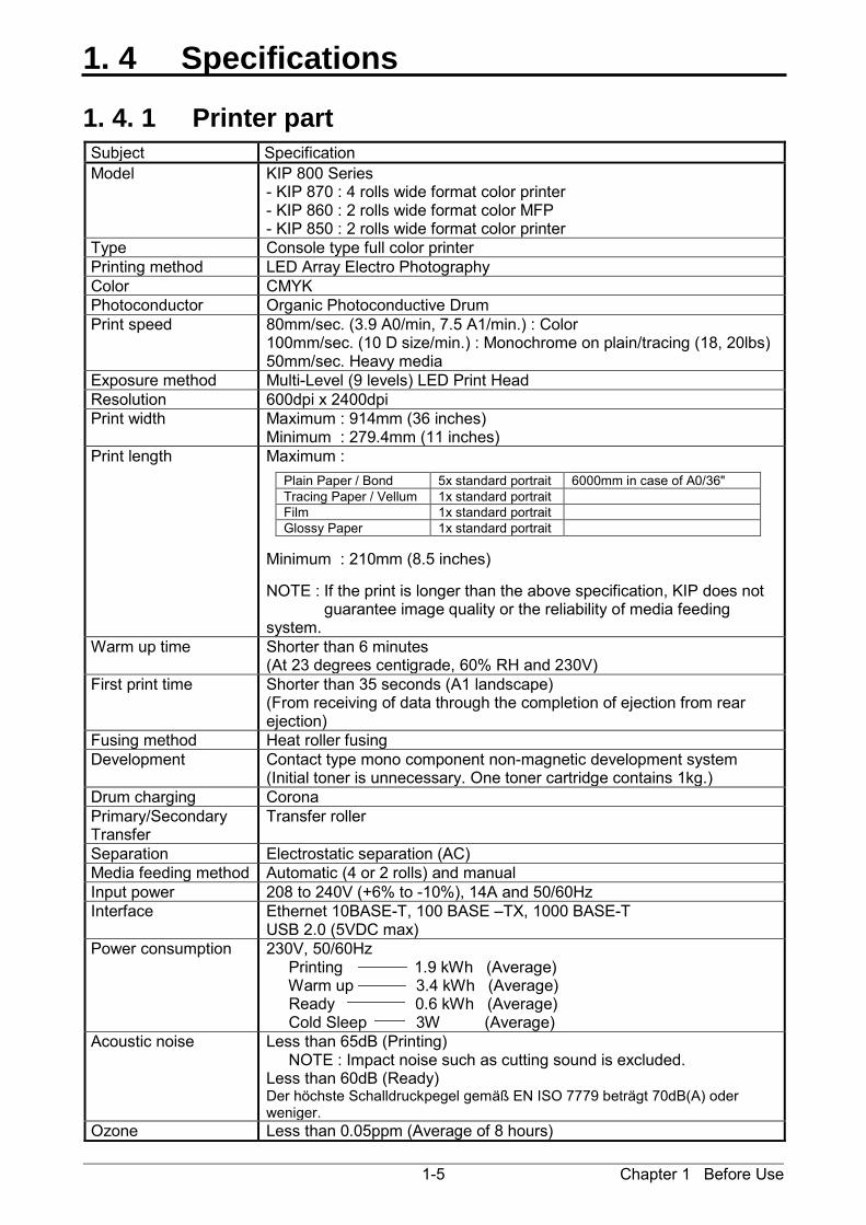
1. 4 Specifications
1. 4. 1 Printer part
Subject Specification Model KIP 800 Series
- KIP 870 : 4 rolls wide format color printer - KIP 860 : 2 rolls wide format color MFP - KIP 850 : 2 rolls wide format color printer
Type Console type full color printer Printing method LED Array Electro Photography Color CMYK Photoconductor Organic Photoconductive Drum Print speed 80mm/sec. (3.9 A0/min, 7.5 A1/min.) : Color
100mm/sec. (10 D size/min.) : Monochrome on plain/tracing (18, 20lbs) 50mm/sec. Heavy media
Exposure method Multi-Level (9 levels) LED Print Head Resolution 600dpi x 2400dpi Print width Maximum : 914mm (36 inches)
Minimum : 279.4mm (11 inches) Print length Maximum :
Minimum : 210mm (8.5 inches) NOTE : If the print is longer than the above specification, KIP does not guarantee image quality or the reliability of media feeding system.
Plain Paper / Bond 5x standard portrait 6000mm in case of A0/36" Tracing Paper / Vellum 1x standard portrait Film 1x standard portrait Glossy Paper 1x standard portrait
Warm up time Shorter than 6 minutes (At 23 degrees centigrade, 60% RH and 230V)
First print time Shorter than 35 seconds (A1 landscape) (From receiving of data through the completion of ejection from rear ejection)
Fusing method Heat roller fusing Development Contact type mono component non-magnetic development system
(Initial toner is unnecessary. One toner cartridge contains 1kg.) Drum charging Corona Primary/Secondary Transfer
Transfer roller
Separation Electrostatic separation (AC) Media feeding method Automatic (4 or 2 rolls) and manual Input power 208 to 240V (+6% to -10%), 14A and 50/60Hz Interface Ethernet 10BASE-T, 100 BASE –TX, 1000 BASE-T
USB 2.0 (5VDC max) Power consumption 230V, 50/60Hz
Printing 1.9 kWh (Average) Warm up 3.4 kWh (Average) Ready 0.6 kWh (Average) Cold Sleep 3W (Average)
Acoustic noise Less than 65dB (Printing) NOTE : Impact noise such as cutting sound is excluded. Less than 60dB (Ready) Der höchste Schalldruckpegel gemäß EN ISO 7779 beträgt 70dB(A) oder weniger.
Ozone Less than 0.05ppm (Average of 8 hours)

Chapter 1 Before Use 1-6
Subject Specification Dimensions KIP 870 : 1,500mm (W) x 1,080mm (D) x 1,220mm (H)
KIP 860 : 1,500mm (W) x 1,080mm (D) x 1,155mm (H) KIP 850 : 1,500mm (W) x 1,080mm (D) x 1,015mm (H) NOTE : Touch panel and upper trays are not included.
Weight KIP 870 About 530kg (1168lb) KIP 860 About 510kg (1124lb) KIP 850 About 485kg (1069lb)
Media Bond/Plain paper - 70 to 80 g/m2 (Monochrome : 100mm /sec.) - 70 to 90 g/m2 (Color : 80mm /sec.) - 90 to 150 g/m2 (Heavy media is used : 50mm /sec.) Tracing paper - Film - g/m2 Gloss - g/m2
Environmental condition
Standard Environment : 23oC and 60% Temperature 10 to 30 degrees centigrade Humidity 15 to 80% RH
Storage condition of consumables
Print media Wrap the media surely to shut out the humidity. Toner Keep the toner cartridge away from the direct sunlight, and store it in the condition of 0 - 35 oC and 10 - 85% RH.
Hardware option - Online Auto Stacker - Online Folder
NOTE These specifications may be changed without notice.

Chapter 1 Before Use 1-7
1. 4. 2 Scanner part (KIP 860 only)
Subject Specification Scanning method Contact Image Sensor (CIS)
(5 pieces of A4 sized CIS) Light source LED (R/G/B) Scanning speed (600 dpi, normal quality) (max)
Monochrome : 65mm/s Grayscale : 65mm/s Color : 22mm/s NOTE : The actual speed may vary by the scan software.
Setting of original Face up Starting point of scan Center Scan width Max: 914.4mm / 36”
Min : 210mm Scan length Max: 6,000mm / 19.7ft (Including the margin area)
Min : 210mm / 8.5” (Including the margin area) NOTE : If the print is longer than 6,000mm, its image quality or the reliability of paper feeding is not guaranteed.
Optical resolution 600dpi Digital resolution 200 / 300 / 400 / 600 dpi Original transportation Sheet through type Transportable original thickness
Max: 1.60mm Min : 0.05mm NOTE : Suggest to change “It does not guarantee both scan/copy image quality and original feeding reliability in case the original is non-standard size one of which thickness is 0.25mm or thicker.
NOTE The above specifications are subject to change without notice.
Chapter 1 Before Use 1-8
1. 5 Appearance
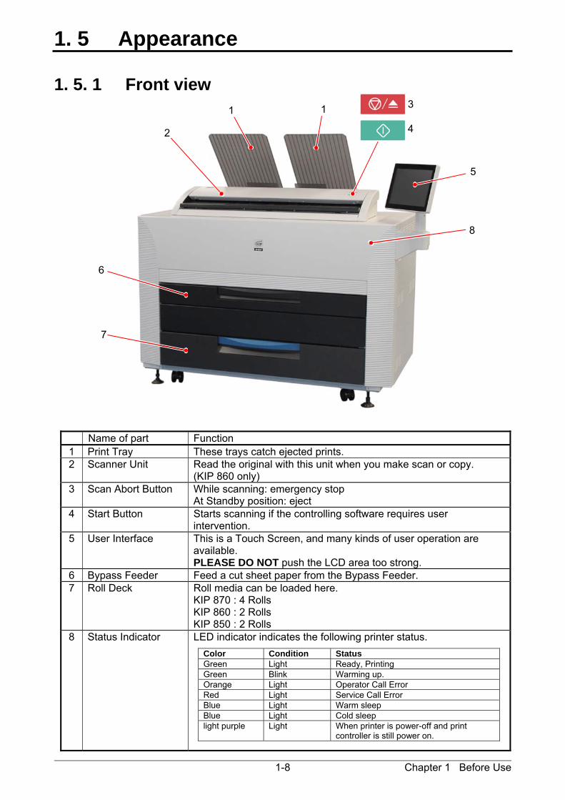
1. 5. 1 Front view
Name of part Function 1 Print Tray These trays catch ejected prints. 2 Scanner Unit Read the original with this unit when you make scan or copy.
(KIP 860 only) 3 Scan Abort Button While scanning: emergency stop
At Standby position: eject 4 Start Button Starts scanning if the controlling software requires user
intervention. 5 User Interface This is a Touch Screen, and many kinds of user operation are
available. PLEASE DO NOT push the LCD area too strong.
6 Bypass Feeder Feed a cut sheet paper from the Bypass Feeder. 7 Roll Deck Roll media can be loaded here.
KIP 870 : 4 Rolls KIP 860 : 2 Rolls KIP 850 : 2 Rolls
8 Status Indicator LED indicator indicates the following printer status.
5
1 1 3
4 2
7
6
8
Color Condition StatusGreen Light Ready, PrintingGreen Blink Warming up.Orange Light Operator Call Error Red Light Service Call Error Blue Light Warm sleepBlue Light Cold sleeplight purple Light When printer is power-off and print
controller is still power on.
Chapter 1 Before Use 1-9
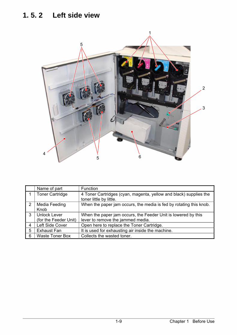
1. 5. 2 Left side view
Name of part Function 1 Toner Cartridge 4 Toner Cartridges (cyan, magenta, yellow and black) supplies the
toner little by little. 2 Media Feeding
Knob When the paper jam occurs, the media is fed by rotating this knob.
3 Unlock Lever (for the Feeder Unit)
When the paper jam occurs, the Feeder Unit is lowered by this lever to remove the jammed media.
4 Left Side Cover Open here to replace the Toner Cartridge. 5 Exhaust Fan It is used for exhausting air inside the machine. 6 Waste Toner Box Collects the wasted toner.
1
2
3
5 64
5
Chapter 1 Before Use 1-10
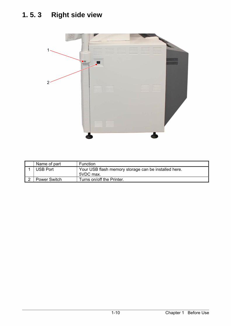
1. 5. 3 Right side view
Name of part Function 1 USB Port Your USB flash memory storage can be installed here.
5VDC max. 2 Power Switch Turns on/off the Printer.
1
2

Chapter 1 Before Use 1-11
1. 5. 4 Rear view
Name of part Function 1 Fuser Knob Rotate this knob when removing the misfed paper in the Fuser
Unit. 2 Upper Exit Unit It ejects prints upward or backward. 3 Fuser Cover Prints come from the opening on this.
Open the Fuser Cover when you remove the paper misfed inside the Fuser Unit.
4 Breaker It is possible to shut off supplying the AC power. 5 Stacker Port For a dedicated Auto Stacker for the Printer (DC24V 2A) 6 Inlet Socket Connect the Power Cord here.
1
3
2
6
4
5
Chapter 1 Before Use 1-12
1. 6 Specifications for the Printing Paper
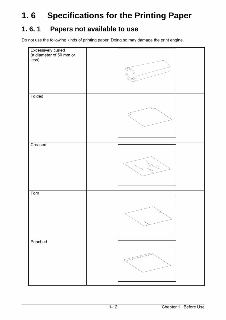
1. 6. 1 Papers not available to use Do not use the following kinds of printing paper. Doing so may damage the print engine.
Excessively curled (a diameter of 50 mm or less)
Folded
Creased
Torn
Punched
Chapter 1 Before Use 1-13
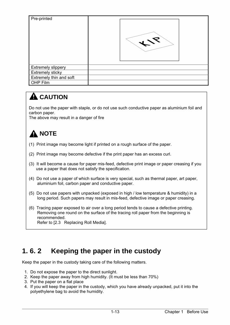
Pre-printed
Extremely slippery Extremely sticky Extremely thin and soft OHP Film
1. 6. 2 Keeping the paper in the custody Keep the paper in the custody taking care of the following matters. 1. Do not expose the paper to the direct sunlight. 2. Keep the paper away from high humidity. (It must be less than 70%) 3. Put the paper on a flat place 4. If you will keep the paper in the custody, which you have already unpacked, put it into the polyethylene bag to avoid the humidity.
CAUTION Do not use the paper with staple, or do not use such conductive paper as aluminium foil and carbon paper. The above may result in a danger of fire NOTE (1) Print image may become light if printed on a rough surface of the paper. (2) Print image may become defective if the print paper has an excess curl. (3) It will become a cause for paper mis-feed, defective print image or paper creasing if you use a paper that does not satisfy the specification. (4) Do not use a paper of which surface is very special, such as thermal paper, art paper, aluminium foil, carbon paper and conductive paper. (5) Do not use papers with unpacked (exposed in high / low temperature & humidity) in a long period. Such papers may result in mis-feed, defective image or paper creasing. (6) Tracing paper exposed to air over a long period tends to cause a defective printing. Removing one round on the surface of the tracing roll paper from the beginning is recommended. Refer to [2.3 Replacing Roll Media].
Chapter 1 Before Use 1-14
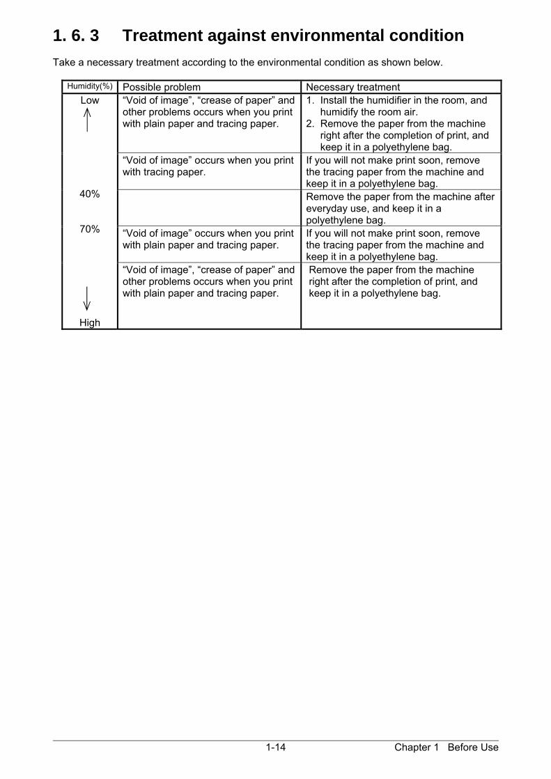
1. 6. 3 Treatment against environmental condition Take a necessary treatment according to the environmental condition as shown below.
Humidity(%) Possible problem Necessary treatment Low
40%
70%
High
“Void of image”, “crease of paper” and other problems occurs when you print with plain paper and tracing paper.
1. Install the humidifier in the room, and humidify the room air. 2. Remove the paper from the machine right after the completion of print, and keep it in a polyethylene bag.
“Void of image” occurs when you print with tracing paper.
If you will not make print soon, remove the tracing paper from the machine and keep it in a polyethylene bag.
Remove the paper from the machine after everyday use, and keep it in a polyethylene bag.
“Void of image” occurs when you print with plain paper and tracing paper.
If you will not make print soon, remove the tracing paper from the machine and keep it in a polyethylene bag.
“Void of image”, “crease of paper” and other problems occurs when you print with plain paper and tracing paper.
Remove the paper from the machine right after the completion of print, and keep it in a polyethylene bag.
Chapter 1 Before Use 1-15
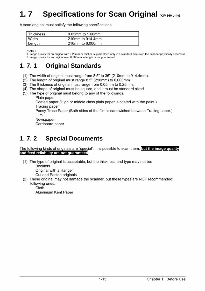
1. 7 Specifications for Scan Original (KIP 860 only) A scan original must satisfy the following specifications.
Thickness 0.05mm to 1.60mm Width 210mm to 914.4mm Length 210mm to 6,000mm
NOTE : 1. Image quality for an original with 0.25mm or thicker is guaranteed only in a standard size even the scanner physically accepts it. 2. Image quality for an original over 6,000mm in length is not guaranteed.
1. 7. 1 Original Standards (1) The width of original must range from 8.5” to 36” (210mm to 914.4mm). (2) The length of original must range 8.5” (210mm) to 6,000mm (3) The thickness of original must range from 0.05mm to 0.25mm. (4) The shape of original must be square, and it must be standard sized. (5) The type of original must belong to any of the followings. Plain paper Coated paper (High or middle class plain paper is coated with the paint.) Tracing paper Pansy Trace Paper (Both sides of the film is sandwiched between Tracing paper.) Film Newspaper Cardboard paper
1. 7. 2 Special Documents The following kinds of originals are “special”. It is possible to scan them, but the image quality and feed reliability are not guaranteed. (1) The type of original is acceptable, but the thickness and type may not be: Booklets Original with a Hanger Cut and Pasted originals (2) These original may not damage the scanner, but these types are NOT recommended: following ones. Cloth Aluminium Kent Paper
Chapter 1 Before Use 1-16
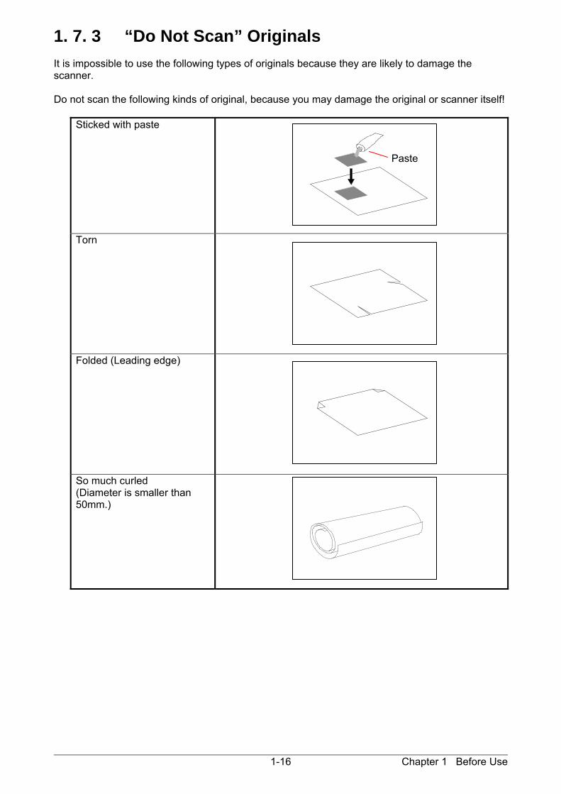
1. 7. 3 “Do Not Scan” Originals It is impossible to use the following types of originals because they are likely to damage the scanner. Do not scan the following kinds of original, because you may damage the original or scanner itself!
Sticked with paste
Torn
Folded (Leading edge)
So much curled (Diameter is smaller than 50mm.)
Paste
Chapter 1 Before Use 1-17
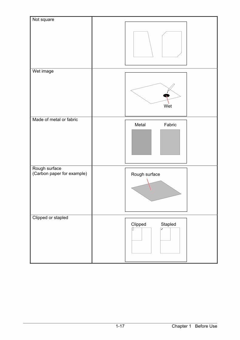
Not square
Wet image
Made of metal or fabric
Rough surface (Carbon paper for example)
Clipped or stapled
Wet
Metal Fabric
Clipped Stapled
Rough surface
Chapter 1 Before Use 1-18
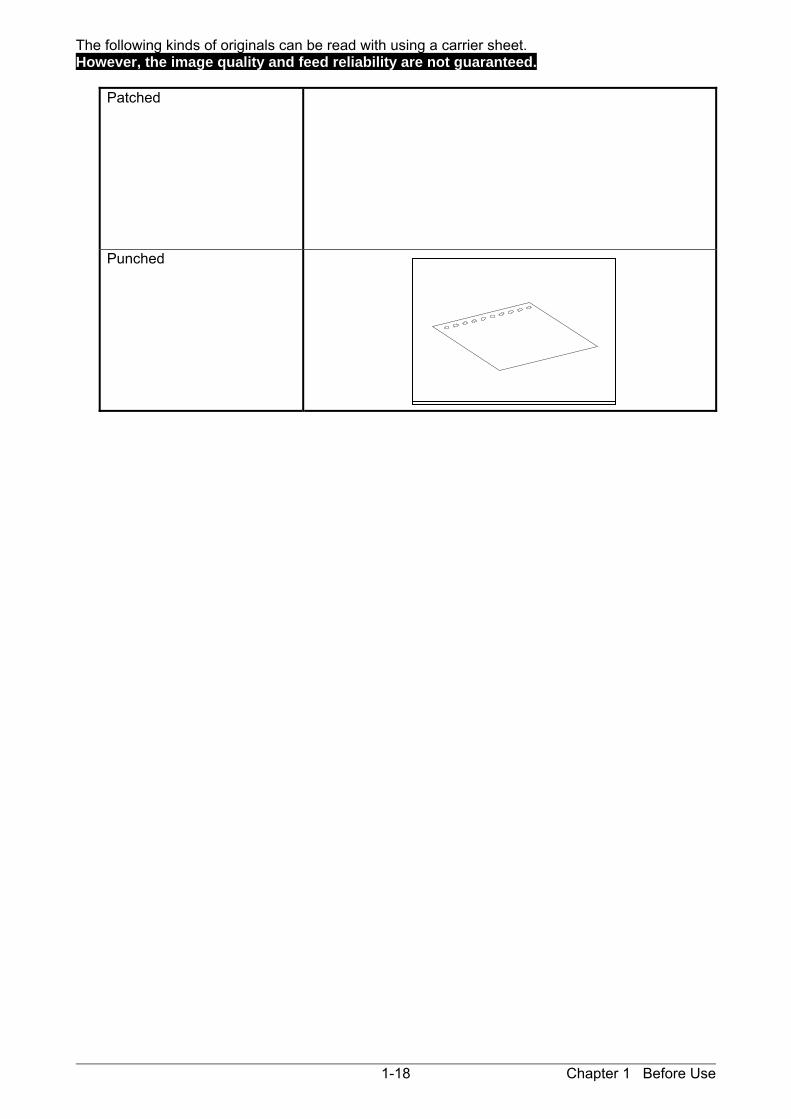
The following kinds of originals can be read with using a carrier sheet. However, the image quality and feed reliability are not guaranteed.
Patched
Punched

Chapter 2 Basic Operations 2-1
Chapter 2
Basic Operations
Page 2. 1 Turning on the Printer 2- 2 2. 2 Turning off the Printer 2- 4 2. 3 Replacing the Roll Media 2- 6 2. 4 Placing Cut Sheet Media 2-13 2. 5 Replacing the Toner Cartridge 2-14 2. 6 Replacing the Waste Toner Box 2-17 2. 7 Copying (for KIP860) 2-21 2. 8 Stop of Scan or Copy (for KIP860) 2-24

Chapter 2 Basic Operations 2-2
2. 1 Turning on the Printer 1. Plug the Printer to an exclusive wall outlet. 2. Press “ | ” side of the Power Switch.
3. The status indicator on the upper right of the printer is blinking and the warming-up is started.
NOTE
The machine does not operate at all If the circuit breaker is turned off. Flip up the circuit breaker switch to turn on the power supply.
WARNING
Please confirm the outlet satisfies the following condition before plugging the Printer into. 208-240V (+6% to -10%), 16A, and 50/60Hz
Press this side

Chapter 2 Basic Operations 2-3
4. The Printer will get ready about 6 minutes after turning on. The Status Indicator stops blinking and lights green when ready. Make a copy or print from outer devices.

Chapter 2 Basic Operations 2-4
2. 2 Turning off the Printer 1. Press “ ” side of the Power Switch. 2. The Status Indicator light purple while the embedded controller unit is shutting down.
It will turn off in few minutes.
NOTE The controller unit starts shutdown process after turning off the Printer, and it will take about 1 minutes until complete shut down. Do not unplug the Printer from the outlet for about 1 minutes after turning off therefore. The controller unit may be broken if the Printer is unplugged before the completion of shut down process.
Press this side
Chapter 2 Basic Operations 2-5
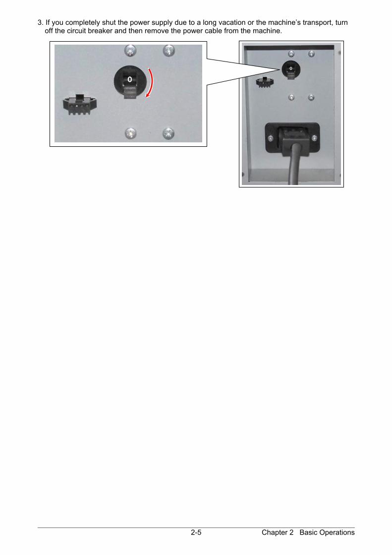
3. If you completely shut the power supply due to a long vacation or the machine’s transport, turn off the circuit breaker and then remove the power cable from the machine.

Chapter 2 Basic Operations 2-6
2. 3 Replacing the Roll Media
UI displays a sign of “Roll Replacement” when the used roll media gets empty. Follow the later procedure to load a new roll media. 1. Open the Roll Deck (1) that has empty roll media.
With catching the Flanges (2) on both sides, lift and remove the core of roll (3). 2. Pull the green lever (4) on each Flange (2), which releases the core of roll (3). Remove both Flanges (2). 3. With sliding the Slide Guides (5) left and right by hand, align them to the width guide lines that match the width of actual media to be loaded. (Sliding either left or right one of 2 Side Guides also moves the other one by the same amount.)
3
4
2
2
3
2
1
2
2
5
5

Chapter 2 Basic Operations 2-7
4. Insert both Flanges (2) deep into the core of new roll media until they stop.
NOTE (1) Insert Flanges (2) deep enough into the core of roll media until their inside rims surely
touch the side face of roll media with having no gap. Correct: Fully inserted Incorrect: There is gap (2) Be careful not to be harmed by the saw-toothed edge (6) when handling the Flanges (2).
2
Inside Rim Inside Rim
Gap
6
OK NG

Chapter 2 Basic Operations 2-8
5. Turn down the lever (4) in either way until they completely stop, which lets the Flange to surely hold the roll media.
6. Fit both Flanges correctly into both Slide Guides (5) in the roll deck. (See next page for more explanation)
4 4
5

Chapter 2 Basic Operations 2-9
NOTE (1) Note the position of leading edge. It should be on the bottom side when directed to the media feeding path. Correct: Leading edge is on bottom side Incorrect: Leading edge is on top side (2) The outside rim (7) of the Flange must be aligned with the tip of black triangle (8) for
correct gear engagement. If not, the Flange may come off from correct position and may result in incorrect media feeding.
C
to media feeding path
8
7
Correct Incorrect
OK NG
7
8
to media feeding path

Chapter 2 Basic Operations 2-10
7. Insert the leading edge into a slit under the Guide Plate (9) until it touches the feeding roller (10).
Roll 1
Roll 3
Roll 2
Roll 4
9 9
10
10
Front Deck (Roll 1 / 3) Rear Deck (Roll 2 / 4)
9 9
10 10
10 10

Chapter 2 Basic Operations 2-11
8. Rotate the small green roller (11) in the direction of arrow by hand for allowing the feeding roller to surely hold the leading edge.
9. Push the Roll Deck (1) back in.
11 11
Front Deck (Roll 1 / 3) Rear Deck (Roll 2 / 4)
NOTE (1) Surely close the Roll Deck until it is locked. A paper jam may occur if not locked perfectly.
(2) Be careful not to catch your finger in between Roll Deck drawers.
Roll 2
Roll 4
Roll 1
Roll 3
10
10
1 1

Chapter 2 Basic Operations 2-12
10. Define the media information (media type and width) with using the touch screen. Press [OK].
NOTE Incorrect settings lead to unwanted print results (fusing defect, improper image quality).
Chapter 2 Basic Operations 2-13
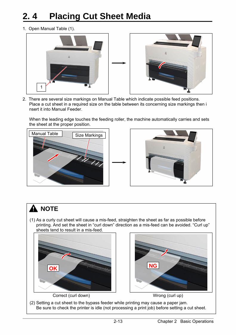
2. 4 Placing Cut Sheet Media 1. Open Manual Table (1). 2. There are several size markings on Manual Table which indicate possible feed positions.
Place a cut sheet in a required size on the table between its concerning size markings then i nsert it into Manual Feeder. When the leading edge touches the feeding roller, the machine automatically carries and sets the sheet at the proper position.
NOTE (1) As a curly cut sheet will cause a mis-feed, straighten the sheet as far as possible before
printing. And set the sheet in “curl down” direction as a mis-feed can be avoided. “Curl up” sheets tend to result in a mis-feed.
Correct (curl down) Wrong (curl up)
(2) Setting a cut sheet to the bypass feeder while printing may cause a paper jam. Be sure to check the printer is idle (not processing a print job) before setting a cut sheet.
1
NG
OK
Size MarkingsManual Table
Chapter 2 Basic Operations 2-14
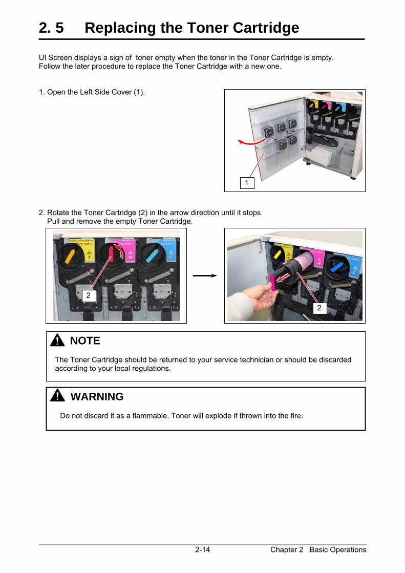
2. 5 Replacing the Toner Cartridge UI Screen displays a sign of toner empty when the toner in the Toner Cartridge is empty. Follow the later procedure to replace the Toner Cartridge with a new one. 1. Open the Left Side Cover (1). 2. Rotate the Toner Cartridge (2) in the arrow direction until it stops. Pull and remove the empty Toner Cartridge.
NOTE The Toner Cartridge should be returned to your service technician or should be discarded according to your local regulations.
WARNING Do not discard it as a flammable. Toner will explode if thrown into the fire.
1
2
2

Chapter 2 Basic Operations 2-15
3. Prepare a new Toner Cartridge (3) of the same color and shake it enough to loosen the toner. 4. With catching the head part (black part), rotate the body (white part) of the Toner Cartridge in the direction of arrow for more than 3 revolutions. This will have a space in the toner supplying hole. 5. With directing the pointed tip (4) of the color label upside, set the new Toner Cartridge back into
the original position and insert it deep into the machine until it stops.
Direct the pointed tip (4) upside when inserting the cartridge into the machine.
3
4
NOTE Toner Supplying hole does not open enough if the body is not rotated enough, which causes the developer not supplied with enough toner.

Chapter 2 Basic Operations 2-16
6. Rotate the Toner Cartridge (3) in the arrow direction until it stops. 7. Close the Left Side Cover (1).
When the Left Side Door is closed;
The machine goes into “warm up” while processing toner supply. The machine gets “ready” when the toner refilling completes.
1
3
NOTE Be sure that the tip of color sticker should not go further beyond LOCK position.
OK NG

Chapter 2 Basic Operations 2-17
2. 6 Replacing the Waste Toner Box 1. Follow the figures in below to assemble a new Waste Toner Box.
Sticker (Large)
Sticker (Large)
Sticker (Small)
Stickers (Small)
A sheet of Sticker (Large) still remains after assembling the new Waste Toner Box. This is to be used to close the opening of the box when "waste toner full" occurs next time. Please keep this remaining Sticker (Large) at any place where you easily can find it.
Reference

Chapter 2 Basic Operations 2-18
2. Open the Left Side Cover (1). 3. Bring up the Waste Toner Box (2) a little and move it frontward to remove from the machine. 4. Apply the Sticker (3) to close the opening of the Waste Toner, which is included in the WASTE TONER BOX KIT.
NOTE
(1) Do not handle the Waste Toner Box roughly. Otherwise the toner will come out from its open hole.
(2) The Waste Toner Box should be returned to your service technician or should be discarded according to your local regulations.
2
3
WARNING
Do not discard it as a flammable. Toner will explode if thrown into the fire. Please ask the seller for the way of dispose.
1

Chapter 2 Basic Operations 2-19
5. Set the new Waste Toner Box (4) back in the original position. See the following NOTE.
4
NOTE
(1) Place the bottom corner of the box at the inside of the positioning step (5). (2) Make sure the clear film windows (6) is not dirty.
6
4
5

Chapter 2 Basic Operations 2-20
6. Close the Left Side Cover (1).
1

Chapter 2 Basic Operations 2-21
2. 7 Copying (for KIP860) 1. Press [COPY] in UI Home screen. The UI screen may vary depending on your system configuration. (Shown with available options)
2. There are several size markings on Original Table which indicate possible feed positions.
Line up Original Guides (1) with the proper markings according to the original width.
3. Place the original on the Original Table with face up. Then insert it under the Scanner Unit along with Original Guides. When the leading edge touches the original feeding roller, the machine automatically carries and
sets the original at the proper position.
Please refer to the detailed procedure for making a copy, which is included in "GUIDES" in UI Home screen as well.
1
1

Chapter 2 Basic Operations 2-22
4. The KIP 860 will start the copy process.
NOTE The scanner unit does not accept originals automatically during Sleep Mode. Tap on the UI screen and then insert an original.
Pressing START button may be required to start the scan according to the scanner’s controller software. For further details of “Auto Start”, see the software’s document.
Reference
Start Button

Chapter 2 Basic Operations 2-23
The KIP 800 Series has 2 print delivery system, the print tray / rear stacking equipment.
For the front stacking, the printer will inform you of “Upper Bin Full” on exceeding capacity of stacking. If the UI screen shows “Upper Bin Full”, remove all the prints on the print tray. For further information of switching front / back delivery, see KIP Multi-Touch User Guide.
NOTE For the front stacking, gently lift up the prints on the print tray to the arrow direction to avoid rubbing the print surface. A large number of prints should be removed in several sheets.
Correct: Gently lift up and remove Wrong: Do not pull downward
OK NG
Chapter 2 Basic Operations 2-24
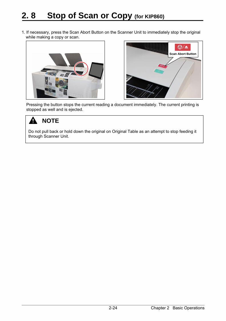
2. 8 Stop of Scan or Copy (for KIP860) 1. If necessary, press the Scan Abort Button on the Scanner Unit to immediately stop the original
while making a copy or scan.
Pressing the button stops the current reading a document immediately. The current printing is stopped as well and is ejected.
NOTE Do not pull back or hold down the original on Original Table as an attempt to stop feeding it through Scanner Unit.
Scan Abort Button
Chapter 3 Error Correction 3-1
Chapter 3
Error Correction Page 3. 1 Mis-feed Error 3- 2 3. 1. 1 Roll Deck Section Jam (Deck 1, 2, 3, 4 Mis-feed) 3- 3 3. 1. 2 Manual Feeder Section Jam (Feeder part Mis-feed (1)) 3- 5 3. 1. 3 Media Feed Section Jam (Registration Mis-feed, Feeder part Mis-feed
(1), (2), (3)) 3- 6 3. 1. 4 Exit Section Jam 1 (Exit Mis-feed, Separation Mis-feed (1)) 3- 8 3. 1. 5 Exit Section Jam 2 (Exit Top Mis-feed) 3-11 3. 1. 6 Scanner section Jam (Scanner document jam) (for KIP860) 3-12 3. 2 Door Open 3-13 3. 2. 1 Roll Deck (Deck 1 Open, Deck 2 Open) 3-13 3. 2. 2 Left Side Cover (Left Side Cover Open) 3-13 3. 2. 3 Fuser Cover (Fuser Cover Open) 3-14 3. 2. 4 Upper Exit Unit (Paper Exit Door Open) 3-14 3. 2. 5 Scanner Unit (Scanner feeder open) 3-15 3. 3 Other Operator Call 3-16 3. 3. 1 Roll Replacement 3-16 3. 3. 2 Toner Empty 3-16 3. 3. 3 Waste Cartridge full 3-17 3. 3. 4 Web Cleaner Empty 3-17 3. 4 Service Call Error 3-18

Chapter 3 Error Correction 3-2
3. 1 Mis-feed Error "XXXX Mis-feed" is displayed in the UI screen when the media is jammed. The jammed locat ion when displaying "Mis-feed" is shown below.
Scanner Section
Media Feed Section Manual Feeder Section
Exit Section 1
Exit Section 2
Roll Deck Section
NOTE (1) Be careful not to get paper cuts on your hand. (2) Gently remove a jammed paper. When it does not reach Fuser Unit, toner on it may spill
off. If toner gets into eyes or your mouth, immediately rinse them with water and contact a doctor.
(3) Gently remove a jammed paper. When it does not reach Fuser Unit, toner on it may spill
off on your cloth. Dust off your cloth. Use cold water to wash in out. Using hot water may leave a stain.

Chapter 3 Error Correction 3-3
3. 1. 1 Roll Deck Section Jam (Deck 1, 2, 3, 4 Mis-feed )
Clear the Paper Mis-feed using the following procedure: 1. Open the Roll Deck (1) in issue. And then rewind the roll onto the media core. 2. If the leading edge of the media is torn or folded, cut it off.
1
Roll Deck Section Deck 1 Mis-feed
Roll Deck Section Deck 1 Mis-feed Deck 3 Mis-feed (for KIP870)
Roll Deck Section Deck 2 Mis-feed Deck 4 Mis-feed (for KIP870)

Chapter 3 Error Correction 3-4
3. Set the roll media correctly. 4. Close the Roll Deck.
NOTE The outside rim of Flange should meet the black triangle marked on Slide Guide. Otherwise the roll media may fall in Roll Deck or result in an incorrect media feeding. Correct Wrong
OK NG
Out of position
Front Deck (Roll 1 / 3) Rear Deck (Roll 2 / 4)

Chapter 3 Error Correction 3-5
3. 1. 2 Manual Feeder Section Jam (Feeder part Mis-feed (1))
1. Pull out the mis-feed cut sheet from the Manual Feeder.
NOTE The mis-feed cut sheet should be replaced with a new one if its leading edge has a torn or fold. Or it should be used upside down to keep the damaged edge from been inserted. An extremely creased cut sheet may cause mis-feed again.
Manual Feeder Section Feeder part Mis-feed (1)

Chapter 3 Error Correction 3-6
3. 1. 3 Media Feed Section Jam (Registration Mis-feed, Feeder part Mis-feed (1), (2), (3))
1. Open the Left Side Cover (1). 2. Turn the Lever (2) to the arrow direction.
2
2
1
Media Feed SectionResistration Mis-feed
Media Feed Section Feeder part Mis-feed (1)
Media Feed Section Feeder part Mis-feed (2)
Media Feed Section Feeder part Mis-feed (3)

Chapter 3 Error Correction 3-7
3. Remove the jammed media. 4. In case that the media is pinched by the roller and cannot be removed, rotate the Paper Feeding Knob (3) to feed the media to the Feeder Unit, and then remove it.
3 3
Chapter 3 Error Correction 3-8
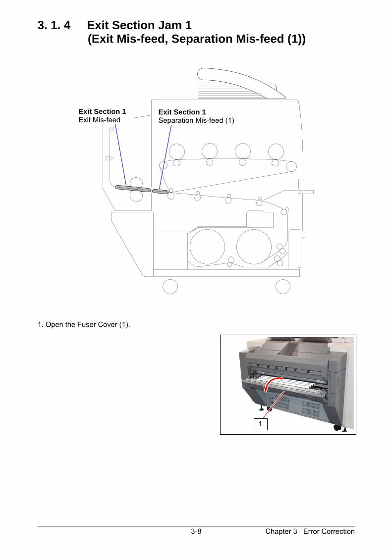
3. 1. 4 Exit Section Jam 1 (Exit Mis-feed, Separation Mis-feed (1))
1. Open the Fuser Cover (1).
1
Exit Section 1 Exit Mis-feed
Exit Section 1 Separation Mis-feed (1)
Chapter 3 Error Correction 3-9
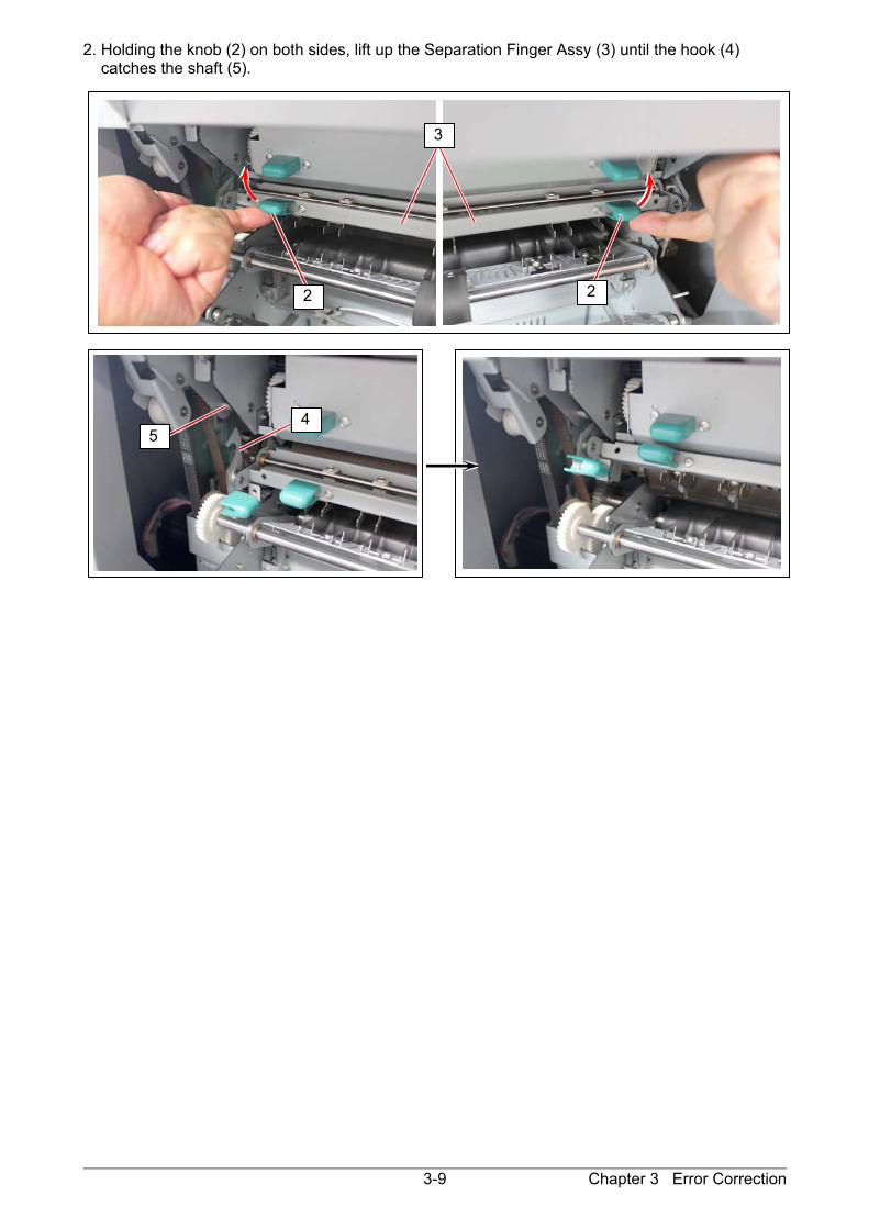
2. Holding the knob (2) on both sides, lift up the Separation Finger Assy (3) until the hook (4) catches the shaft (5).
22
3
4 5

Chapter 3 Error Correction 3-10
3. Rotate the Fuser Knob (6) to the arrow direction to feed the media to the exit direction, and then remove it. 4. Pull up the knob (7) on the both sides to put back the Separation Finger Assy to the original position.
WARNING
There are extremely hot parts inside the Fuser Unit. Do not touch any parts in the Fuser Unit, or you will be burnt. Also the mis-fed media can be very hot. Be careful not to get burnt when you remove it.
6
7 7

Chapter 3 Error Correction 3-11
3. 1. 5 Exit Section Jam 2 (Exit Top Mis-feed) 1. Remove the Exit Tray 2 (1). 2. Open the Upper Exit Unit (2) and then remove mis-feed paper (3).
1
3
2
Exit Section 2 Exit Top Mis-feed
Chapter 3 Error Correction 3-12
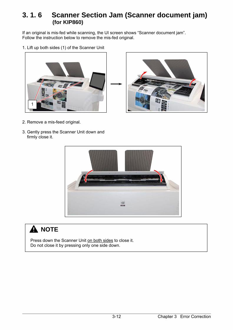
3. 1. 6 Scanner Section Jam (Scanner document jam) (for KIP860)
If an original is mis-fed while scanning, the UI screen shows “Scanner document jam”. Follow the instruction below to remove the mis-fed original. 1. Lift up both sides (1) of the Scanner Unit 2. Remove a mis-feed original. 3. Gently press the Scanner Unit down and
firmly close it.
NOTE Press down the Scanner Unit on both sides to close it. Do not close it by pressing only one side down.
1
Chapter 3 Error Correction 3-13
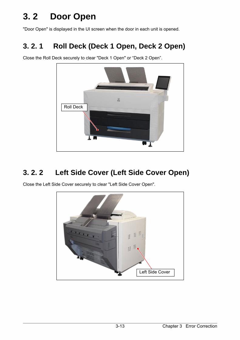
3. 2 Door Open "Door Open" is displayed in the UI screen when the door in each unit is opened.
3. 2. 1 Roll Deck (Deck 1 Open, Deck 2 Open) Close the Roll Deck securely to clear "Deck 1 Open" or “Deck 2 Open”. 3. 2. 2 Left Side Cover (Left Side Cover Open) Close the Left Side Cover securely to clear "Left Side Cover Open".
Roll Deck
Left Side Cover
Chapter 3 Error Correction 3-14
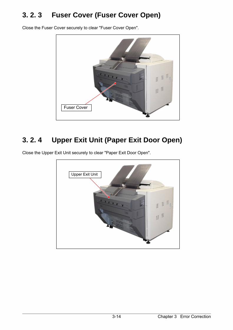
3. 2. 3 Fuser Cover (Fuser Cover Open) Close the Fuser Cover securely to clear "Fuser Cover Open". 3. 2. 4 Upper Exit Unit (Paper Exit Door Open) Close the Upper Exit Unit securely to clear "Paper Exit Door Open".
Fuser Cover
Upper Exit Unit
Chapter 3 Error Correction 3-15
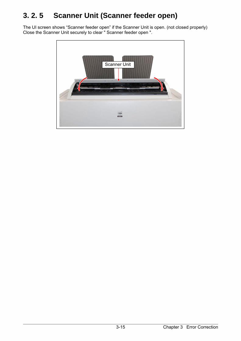
3. 2. 5 Scanner Unit (Scanner feeder open) The UI screen shows “Scanner feeder open” if the Scanner Unit is open. (not closed properly) Close the Scanner Unit securely to clear " Scanner feeder open ".
Scanner Unit
Chapter 3 Error Correction 3-16
3. 3 Other Operator Call
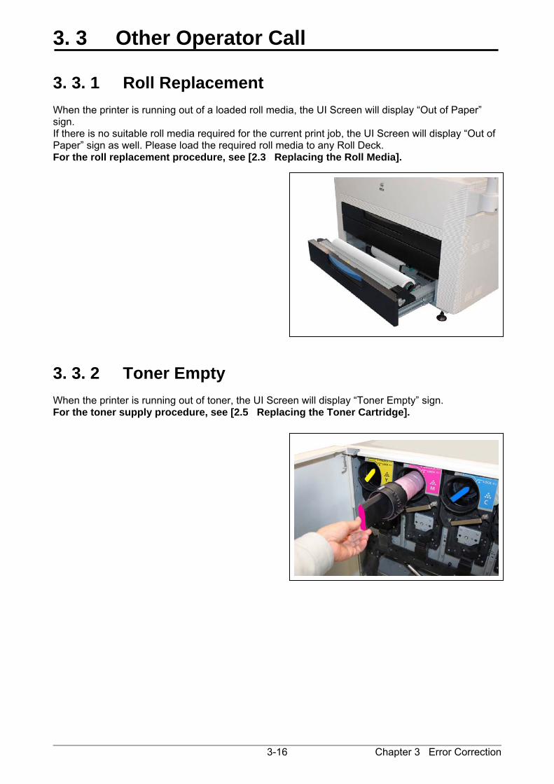
3. 3. 1 Roll Replacement When the printer is running out of a loaded roll media, the UI Screen will display “Out of Paper” sign. If there is no suitable roll media required for the current print job, the UI Screen will display “Out of Paper” sign as well. Please load the required roll media to any Roll Deck. For the roll replacement procedure, see [2.3 Replacing the Roll Media].
3. 3. 2 Toner Empty When the printer is running out of toner, the UI Screen will display “Toner Empty” sign. For the toner supply procedure, see [2.5 Replacing the Toner Cartridge].

Chapter 3 Error Correction 3-17
3. 3. 3 Waste Cartridge full When the Waste Toner Box is full, the UI screen shows “Waste Cartridge full.” The printer does not restart operation until the Waste Toner Box is properly replaced. For replacement procedure, see [2.6 Replacing the Waste Toner Box].
3. 3. 4 Web Cleaner Empty Web Cleaner is a component to clean Fuser Unit. When the remaining Web Cleaner is low, the UI screen displays “Web Near End”. (The Printer is still available) “Out of Web” error will appear over a period of time, and the Printer becomes unavailable. Please call your service representative to replace Web Cleaner early.
NOTE
Web Cleaner can be replaced by a well trained technician only.
Waste Toner Box

Chapter 3 Error Correction 3-18
3. 4 Service Call Error If an error with significant effect on the printer occurs, the printer stops the operation and indicates a related Customer Engineer Call Error Code (or description, and its equivalent internal code) on the UI screen. Call the service staff immediately as these problems can be fixed by a well trained technician only. Before calling the service staff, try to turn on/off the Printer. If “Service Call Error” is indicated again, turn off the machine, unplug it, and call the service staff with reporting the error description in the UI screen. CE-Call Error (Service Call Error) - Sensor Error - Motor Error - Cutter Error - Fan Error - Fusing Temperature Error - LED Head Error - High Voltage Power Supply Error - Density Control Error - Belt Skew Error A corresponding description will be displayed in the top column (status region) in the UI screen.
E-xxx

Chapter 4 Maintenance 4-1
Chapter 4
Maintenance Page 4. 1 Scanner Unit (KIP 860 only) 4- 2 4. 1. 1 Scan Glass, Feed Roller, Guide Plate 4- 2 4. 1. 2 Sensor 4- 5 4. 2 Touch Screen 4- 7
Chapter 4 Maintenance 4-2
4. 1 Scanner Unit (KIP860 only)
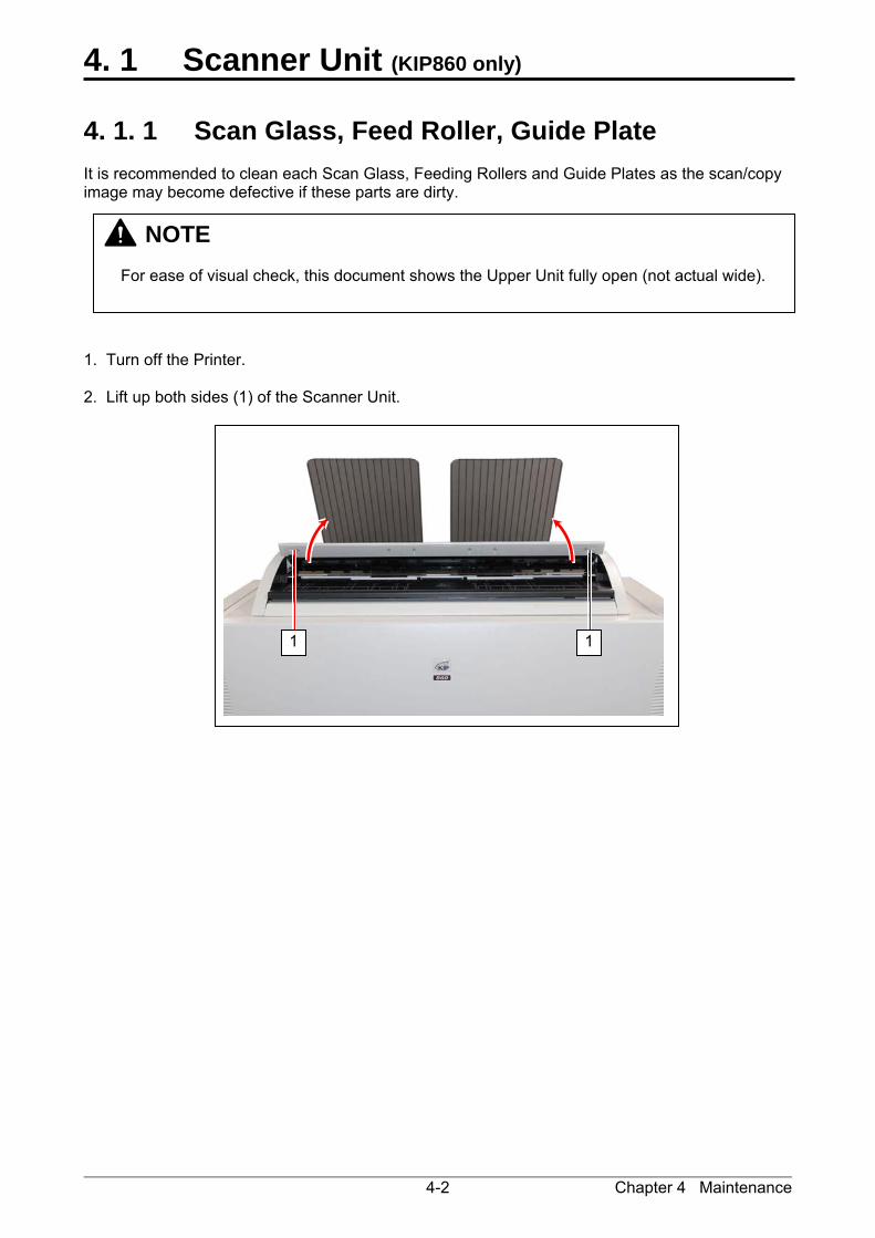
4. 1. 1 Scan Glass, Feed Roller, Guide Plate It is recommended to clean each Scan Glass, Feeding Rollers and Guide Plates as the scan/copy image may become defective if these parts are dirty. 1. Turn off the Printer. 2. Lift up both sides (1) of the Scanner Unit.
NOTE
For ease of visual check, this document shows the Upper Unit fully open (not actual wide).
11

Chapter 4 Maintenance 4-3
3. Gently wipe the Scan Glass (2) and Feed Rollers (white) (3) with a soft cloth. Equal mixture of water and neutral detergent can be used.
4. Wipe the Feed Rollers (rubber) (4) with a dry cloth. 5. Wipe dry the Feeding Rollers.
NOTE Do not use organic solvent, glass cleaner and anti-static spray for the cleaning.
2
3
4
4
4
4

Chapter 4 Maintenance 4-4
6. Wipe the Upper Guide Plate (5) and the Lower Guide Plate (6) with a dry cloth. 7. Gently press Scanner Unit down and firmly close it.
NOTE
Press down Scanner Unit on both side to close it. Do not close it by pressing only one side down.
5
6
5

Chapter 4 Maintenance 4-5
4. 1. 2 Sensor If Sensors are dirty, the original may be detected incorrectly. Perform cleaning or as needed. 1. Turn off the Printer. 2. Lift up both sides (1) of the Scanner Unit.
NOTE
For ease of visual check, this document shows the Upper Unit fully open (not actual wide).
11

Chapter 4 Maintenance 4-6
3. Gently wipe Sensors (2) with a dry cotton bud. 4. Gently press Scanner Unit down and firmly close it.
NOTE
Do not use water, organic solvent, glass cleaner or antistatic spray for cleaning.
NOTE
Press down Scanner Unit on both side to close it. Do not close it by pressing only one side down.
2 2 2 2 2 2
2
Chapter 4 Maintenance 4-7
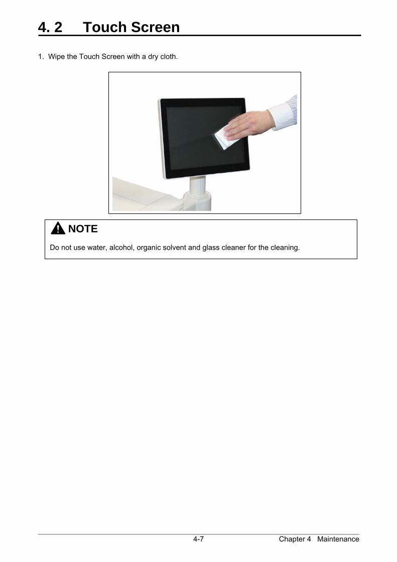
4. 2 Touch Screen 1. Wipe the Touch Screen with a dry cloth.
NOTE Do not use water, alcohol, organic solvent and glass cleaner for the cleaning.