hardware implementation for the hevc fractional motion...
TRANSCRIPT

106 Journal of Integrated Circuits and Systems 2016; v.11 / n.2:106-120
Hardware Implementation for the HEVC Fractional Motion Estimation Targeting Real-Time
and Low-EnergyVladimir Afonso1-2, Henrique Maich1, Luan Audibert1, Bruno Zatt1, Marcelo Porto1,
Luciano Agostini1 and Altamiro Susin2
1Group of Architectures and Integrated Circuits – GACI, Federal University of Pelotas – UFPel, Pelotas, Brazil2Graduate Program in Microelectronics – PGMicro, Federal University of Rio Grande do Sul – UFRGS,
Porto Alegre, Brazile-mail: {vafonso, hdamaich, lpaudibert, zatt, porto, agostini}@inf.ufpel.edu.br; [email protected]
ABSTRACT
This paper presents an energy-aware and high-throughput hardware design for the Fractional Motion Estimation (FME) compliant with the High Efficiency Video Coding (HEVC) standard. An extensive software evaluation was performed to guide the hardware design. The adopted strategy mainly consists in using only the four square-shaped Prediction Unit (PU) sizes rather than using all 24 possible PU sizes in the Motion Estimation (ME). This approach reduces about 59% the total encoding time and, as a penalty, it leads to an increase of only 4% in the bit rate for the same image quality. Together with this simplification, a multiplierless approach, algebraic optimizations and low-power techniques were applied to the hardware design to reduce the hardware-resource usage and the energy consumption, maintaining a high processing rate. The architecture was described in VHDL and the synthe-sis results for ASIC 45nm Nangate standard cells demonstrate that the developed architecture is able to process Ultra-High Definition (UHD) 2160p videos at 60 frames per second (fps), with the lowest power consumption and the lowest hardware-resource usage among the related works.
Index Terms: Video Coding; Hardware Design; Real-Time Processing; HEVC Standard; Fractional Motion Esti-mation.
I. INTRODUCTION
Nowadays, there are several applications invol-ving digital videos, such as digital TV, Blu-Ray, strea-ming, videoconferencing, video calling, security and others. Due to the huge amount of data needed to re-present the video sequences, the use of video compres-sion techniques is mandatory.
The state of the art in terms of video coding stan-dards is the High Efficiency Video Coding (HEVC) [1] and its first version was published in April 2013. The HEVC was developed with the goal of doubling the compression rates obtained by its predecessor, the H.264/AVC (Advanced Video Coding) standard [2], maintaining the same image quality [3]. During the HEVC standardization process, new features were introduced in the video coding tools, including the Motion Estimation (ME) [4]. As a matter of fact, the compression efficiency could be improved at the cost of a computational-effort increase.
The ME step is responsible for important gains in terms of compression efficiency [5]. However, the ME process is the most computationally intensive
step in current video coders. Considering the H.264/AVC, the ME is responsible for about 60-90% of the total encoding time [6]. In the HEVC, the ME is also responsible for an important computational cost, at-taining as much as 62-94% of the total encoding time (see Section III).
In order to apply the ME, the video encoder di-vides the frame into smaller blocks, applying a block matching algorithm to find similar blocks within the reference frames (previously processed frames). In HEVC, these blocks are called Prediction Units (PUs) and they can have sizes from 8x4 or 4x8 samples up to 64x64 samples, totalizing 24 different PU sizes in the ME [4]. Therefore, in order to achieve optimal com-pression efficiency, the encoder should test those 24 PU sizes and choose the best one in terms of rate-dis-tortion efficiency, which requires performing the whole encoding process for each possibility.
Since the motion between the temporal-nei-ghbor frames is not limited to integer positions, the current video standards employ the Fractional Motion Estimation (FME), which allows higher efficiency in the encoding process. The FME can be divided in

Hardware Implementation for the HEVC Fractional Motion Estimation Targeting Real-Time and Low-EnergyAfonso; Maich; Audibert; Zatt; Porto; Agostini & Susin
107Journal of Integrated Circuits and Systems 2016; v.11 / n.2:106-120
two main units: (a) Interpolation Unit, that generates sub-pixel samples around the integer-pixel positions of the block that presents the best result for the Integer Motion Estimation (IME); and (b) Search and Com-parison Unit, where the blocks formed from the new sub-pixel samples are compared with the IME best re-sult. According to our experiments (see Section 3), the FME is responsible for about 50% of the HEVC ME encoding time (or 39% of the total encoding time). This high encoding time is mainly function of the 24 PU sizes [1] that must be evaluated during a regular HEVC ME encoding process.
Considering the high-computational effort of the FME, above mentioned, a hardware support is mandatory. Software solutions, running on Gene-ral Purpose Processors, Digital Signal Processors or Graphic Processing Units demand high energy con-sumption for each frame encoded, when compared to dedicated hardware architectures. This energy con-sumption is especially cumbersome in mobile devices, such as smartphones, which nowadays are expected to process high and ultra-high resolution videos.
For example, if the HEVC FME used all the 24 possible PU sizes to encode an UHD 2160p (3840x2160 pixels) video at 60 frames per second (fps), the FME would need to process 11.94 billions of luminance samples per second. In other words, the FME would require a frequency of 11.94 GHz to rea-ch real-time processing considering the processing of one sample per clock cycle. Even exploiting parallelism with a hardware solution, with the goal of processing more samples per cycle, the required frequency to rea-ch real time is considerably high, which has impacts in terms of energy consumption as well.
Considering the relevance of the hardware-re-sources usage, energy consumption and throughput issues when using the HEVC FME in portable devi-ces, as previously mentioned, the hardware proposed in this article was designed considering some simpli-fications in the HEVC ME, but maintaining the com-pliance with the standard. These simplifications basi-cally consider the reduction of the number of PU sizes evaluated during the ME process, and the evaluated PUs were defined based on a statistical analysis of PU sizes distribution (see Section III). Thus, a complete HEVC FME hardware architecture able to process UHD 2160p videos at 60 fps with low hardware-re-source usage and low energy consumption was desig-ned.
Although HEVC is a recent video-coding stan-dard, there are some published papers proposing har-dware designs for the HEVC FME. However, most of these works, as [7]-[10], are limited to the interpola-tion filters architectures, and they do not present har-dware designs for the Search and Comparison Unit. To the best of our knowledge, there are two works in the
literature that completely implement the HEVC FME, the work [11] and a previous work [12].
This article is organized as follows: Section II presents the state of the art through a HEVC ME ba-ckground and related works. Section III shows HEVC ME evaluations under the perspective of the PU size. Section IV proposes the adopted simplifications to re-duce the IME/FME computational effort. Section V presents a complete hardware design for the FME ba-sed on the developed strategy. Section VI compares the obtained results with the related works. Finally, Section VII concludes this article.
II. BACKGROUND AND RELATED WORKS
The HEVC defines that the frame is split into smaller blocks during the coding process. Prediction steps use the concept of PUs [13]. Considering the ME, the PUs can assume 24 different sizes, with diffe-rent forms: square-shaped, symmetric rectangular-sha-ped and asymmetric rectangular-shaped. In addition, the PU sizes can range from 4x8 samples up to 64x64 samples according to the encoder control. This enco-der control defines the best partition, considering the global result in terms of rate-distortion (evaluating compression rate and image quality) [13].
The FME is used in the current video coding standards, as the HEVC and its predecessor, the H.264/AVC standard. Both standards allow motion vectors with quarter-pixel precision, but some innova-tions were introduced in the HEVC FME to improve the coding efficiency.
The HEVC uses FIR (Finite Impulse Respon-se) filters with 7-taps and 8-taps for the quarter-pixel and the half-pixel interpolation of luminance samples. The HEVC-filter inputs can be the samples at integer positions or sub-pixel samples (quarter and half-pixel samples) previously calculated. After the interpola-tion, a search-and-comparison process using half-pixel and quarter-pixel samples is performed [4]. The HM (HEVC Model) Reference Software [14] defines that the search using the fractional samples occurs around the block with better result considering integer-pixel positions. By default, in the FME of the HEVC, a sear-ch with the eight blocks composed of half-pixel posi-tions is performed firstly, and after that, a search with the eight blocks around the best match of half-pixel blocks is performed using quarter-pixel positions.
Fig. 1 represents the integer samples (blue squares and uppercase letters), as well as the fractional samples (non-blue squares) for the luminance samples interpolation of the HEVC standard. In the Fig. 1-b a 4x4 block is represented, due to the space limitation. When fractional samples are generated, 48 new frac-tional blocks are formed for a new comparison, as can

Hardware Implementation for the HEVC Fractional Motion Estimation Targeting Real-Time and Low-EnergyAfonso; Maich; Audibert; Zatt; Porto; Agostini & Susin
108 Journal of Integrated Circuits and Systems 2016; v.11 / n.2:106-120
also be seen in Fig. 1. In Fig. 1-a, number values in the squares represent the first sample of each new frac-tional block. The gray squares represent the half-pixel samples and the white squares represent the quarter-pi-xel samples. In the Fig. 1-c, the fractional samples are detailed with lowercase letters. As an example, a frac-tional block with quarter-pixel precision is highlighted in green in Fig. 1-b. It is important to note that the number of new blocks for comparison (48 fractional blocks) does not depend of the PU size.
Fifteen equations are used to calculate the frac-tional positions [1] based on FIR filters with 7-taps or 8-taps. The fractional positions a0,0, b0,0, c0,0, d0,0, h0,0 and n0,0 are calculated from the luminance values at integer positions. The calculation for determining the fractional positions e0,0, f0,0, g0,0, i0,0, j0,0, k0,0, p0,0, q0,0 and r0,0 requires values of the positions a0,i, b0,i and c0,i previously calculated, where i varies from -3 to 4 in the vertical direction [1]. It is important to notice that, during the interpolation process, some samples around the block are used to calculate the fractional samples. Since the filter inputs require seven or eight samples, a border of samples is needed to calculate the fractional samples located at the borders of the blocks.
There are some works about the HEVC FME in the scientific literature. However, the most of the papers do not present a complete hardware design for the HEVC FME that includes filtering, searching, and comparison challenges. Only the main papers, which present the most important results in this scenario, are discussed in this section.
The work [7] presents a hardware design for the HEVC FME filters. This work is focused in the ASIC technology and it can process up to 30 fps considering UHD 2160p videos. The work [7] is focused only in the interpolation filtering, i.e., it does not implement the search and comparison unit.
The works [8], [9] and [10] present hardware designs for the interpolation unit of the HEVC FME, which includes memories/buffers to store the samples.
However, they do not implement the search and com-parison. The hardware design described in [8] presents results for both FPGA and ASIC technologies and it is able to process UHD 2160p videos at 30 fps. The works [9] and [10] are previous works and these works show simplified versions for implementing the FME targeting a bigger reduction of the computational ef-fort associated to a high loss in coding efficiency. The-se previous works were focused in FPGA devices and they reach the processing rate of 60 fps considering UHD 2160p videos.
The work [11] completely designs a HEVC FME hardware, including the search and compari-son unit. The results of [11] are obtained considering ASIC technology and the architecture is able to pro-cess UHD 2160p videos in real time by using a lot of hardware resources. The obtained results of the paper [11] were presented considering a complexity-reduc-tion strategy. However, the work [11] does not show a complete evaluation about impacts of the proposed complexity-reduction strategy.
The previous work [12] also presents a who-le HEVC FME hardware, including the search and comparison unit. It presents synthesis results for both FPGA and ASIC technologies and it is able to process UHD 2160p videos at 60 fps. However, this current work presents a more detailed and broader software analysis about IME/FME tools in order to assist the decision for the best complexity-reduction strategy, when compared with the previous work [12]. In terms of hardware implementation, this work reduces the number of buffers needed to store the samples, besides eliminating the use of all intermediate buffers between interpolation and search and comparison units. In addition, the interpolation filters design of this work treats the rounding error due the use of shift, rather the conventional division; implements a better balance of pipeline according to the targeted processing rate; and uses a bit width in the adder outputs according to the maximum possible values. Finally, this work also
Figure 1. A 4x4 block representation: (a) First samples of the 48 fractional blocks generated after the interpolation, (b) 4x4 block (blue squares), and (c) Fractional samples detailing.

Hardware Implementation for the HEVC Fractional Motion Estimation Targeting Real-Time and Low-EnergyAfonso; Maich; Audibert; Zatt; Porto; Agostini & Susin
109Journal of Integrated Circuits and Systems 2016; v.11 / n.2:106-120
employs clock-gating technique, which significantly reduces the hardware-resource usage and the energy consumption when compared to the previous work [12]. Therefore, there is still space for a complete FME hardware design able to process UHD videos in real time, but with a lower hardware cost, a lower ener-gy consumption and better evaluation of penalties in terms of coding efficiency.
III. HEVC FME EVALUATIONS
Evaluations with the HM [14] software are very important when the focus of the work is hardware de-sign. Since the HM allows the conduction of experi-ments under specific scenarios through the use of con-figuration parameters and/or changes in the reference code, the behavior of a particular video coding tool can be evaluated. This way, strategies targeting hardware design can be better evaluated.
Hence, some experiments were performed using the HM with the goal to explore the ME/FME video coding tool targeting the hardware design. The experiments were done to test which types of ME/FME simplifications could result in an expressive com-plexity reduction together with a most efficient har-dware design and with lower impacts on the encoding efficiency. These experiments were divided in two sets and they were conducted to evaluate: (a) The impact in terms of compression rate and encoding time of the ME and the FME in the HEVC; and (b) The PU sizes most frequently selected during the encoding and their representativeness in the frames, i.e., the PU sizes that present the best results in the encoding process.
Each one of the experiments sets will be bet-ter explained in the following subsections. Before that, a subsection presents some important considerations about the test and configuration conditions used in the evaluations.
A. Experimental Setup
The test conditions used in the evaluations were obtained by the JCT-VC (Join Collaborative Team on Video Coding) recommendation [15], also known as CTCs (Common Test Conditions). This document de-fines eight test conditions that combine high efficiency (Main 10 Profile) or low complexity (Main Profile) profiles with temporal configurations called Intra Only (IO), Random Access (RA) and Low Delay (LD).
The CTC defines 24 video sequences that must be considered in the experiments. These video sequen-ces are divided in classes according to their resolu-tions and features. Class A has four video sequences at the WQXGA resolution (2560x1600 pixels), Class B has five sequences at the HD 1080p resolution
(1920x1080 pixels), Class C has four sequences at the WVGA resolution (832x480 pixels), Class D has four videos at the WQVGA resolution (416x240 pixels), Class E has three sequences at the HD 720p resolution (1280x720 pixels) and Class F has four videos at the different resolutions, one video at the XGA resolution (1024x768 pixels), two videos at the HD 720p resolu-tion and one video at the WVGA resolution.
Although Class F presents videos at different resolutions, all those are screen content videos, whi-ch present different characteristics from the all other classes. The sequences have different number of frames and frame rates, but the CTC defines that all sequences and frames must be encoded in the experiments.
This way, all experiments done in this work used the Main Profile and the four QPs (Quantization Pa-rameters) recommended in the CTC document [15], (QP=22, 27, 32, and 37). All evaluations were perfor-med through the HM 13.0rc1 version [14].
Each one of the experiment sets is presented in the next subsections.
B. ME and FME Coding Efficiency Evaluation
The first set of experiments was performed to investigate the relevance of the inter-frames prediction and, especially, the relevance of the FME in the HEVC. Basically, this set of experiments was performed to eval-uate the impact in terms of compression rate and en-coding time when the inter-frames prediction (where the ME and FME are included) are removed from the HEVC encoder. The adopted strategy to obtain the inter-frames prediction impact is simple. Firstly, all se-quences are encoded with the IO configuration, which does not use the inter-frames prediction. After, all se-quences are encoded with the LD and RA configura-tions. Hence, the obtained values in terms of compres-sion and encoding time can be compared. The results for this evaluation are presented in the Table I. This table presents the percentage increase in the BD-Rate metric [16] when the inter-frames prediction is not used (ME/FME are not used). The increase of the BD-Rate values represents worse compression rates since BD-Rate represents the percentage variation in the bit rate for the same image quality. These values were ob-tained through the average values of all sequence class-es and QP values.
Though of this drastic increase in the BD-Rate when the inter-frames prediction is not used, about 554.02% for the RA configuration, on average, Table I also shows a great percentage decrease in the encod-ing time when the inter-frames prediction is not used. This percentage decrease in the encoding time reaches about 74.01% considering the RA Configuration, on average. Considering all video sequences individually, this percentage decrease varies between 62 and 94%.

Hardware Implementation for the HEVC Fractional Motion Estimation Targeting Real-Time and Low-EnergyAfonso; Maich; Audibert; Zatt; Porto; Agostini & Susin
110 Journal of Integrated Circuits and Systems 2016; v.11 / n.2:106-120
In the sequence, the impact of the HEVC FME was verified. Basically, some changes were done in the HM code to disable the FME. Therefore, all sequences were encoded in the LD and RA configurations with and without FME, allowing a comparison of results in terms of bit rate and encoding time. The BD-Rate and encoding time results about the FME impact can be seen in the Table II. On the one hand, the values in Table II show significant increase in the BD-Rate when the FME is disabled, about 10.66% for the RA config-uration, on average. On the other hand, the encoding time has also an important decrease of 37.28% for the RA Configuration, on average.
It is important to note that the BD-Rate results for the classes E and F are dissonant when compared with the other classes. These differences occur due to the aspects of the video sequences, which involve some regions with high motion and other regions with static background.
Through the evaluations about the impact of the inter-frames prediction and the impact of the FME in the HEVC, it is possible to see the importance of those tools in terms of compression, and also how much the computational effort associated with them are signifi-cant in the HEVC scenario.
In the next evaluations, only the LD and the RA configurations were used. Since the scope of the next experiments is point out the ME/FME simplifications that could support an efficient hardware design for the HEVC FME, the IO configuration was not used be-cause this configuration does not use ME/FME.
C. Occurrences and Representativeness of PU Sizes
The second set of experiments was conducted with the goal to sustain a computational-effort reduc-tion strategy for the ME/FME (see Section 4) be able to support an efficient hardware design, maintaining good results in terms of compression.
As previously mentioned, the major amount of the computational effort of the HEVC is due to the de-cision of which methods of encoding and PU sizes must be used in the ME, since 24 PU sizes must be evaluat-ed during the encoding. Furthermore, all these 24 PU sizes must be processed by other encoding tools (Trans-forms and Quantization, for instance) to define which size presents the best compression versus image quality tradeoff. In conclusion, this process has a high cost and a reduction in this computational effort is highly desirable.
Table I. Percentage variations in BD-Rate and encoding time for HEVC encoding without Inter-Frames Prediction.
Sequence ClassesLD Configuration (%) RA Configuration (%)
BD-Rate increase Encoding Time reduction BD-Rate increase Encoding Time reduction
Class A - 2560x1600* – – 350.52 83.84
Class B - 1920x1080 429.32 83.47 461.19 71.80
Class C - 832x480 386.16 78.89 433.86 71.40
Class D - 416x240 416.79 80.70 479.17 69.78
Class E - 1280x720** 1965.93 69.24 – –
Class F- several 3055.73 81.82 1045.34 73.23
Average 1250.78 78.82 554.02 74.01
* Class A is not used with the LD Configuration, according to the CTCs.** Class E is not used with the RA Configuration, according to the CTCs.
Table II. Percentage variations in BD-Rate and encoding time for HEVC encoding with FME disabled.
Sequence ClassesLD Configuration (%) RA Configuration (%)
BD-Rate increase Encoding Time reduction BD-Rate increase Encoding Time reduction
Class A - 2560x1600* – – 7.64 38.03
Class B - 1920x1080 11.27 41.12 10.45 38.84
Class C - 832x480 14.67 36.68 14.01 33.02
Class D - 416x240 21.48 38.01 16.23 35.22
Class E - 1280x720** 9.66 48.78 – –
Class F- several 5.67 41.17 4.95 41.28
Average 12.55 41.15 10.66 37.28
* Class A is not used with the LD Configuration, according to the CTCs.** Class E is not used with the RA Configuration, according to the CTCs.

Hardware Implementation for the HEVC Fractional Motion Estimation Targeting Real-Time and Low-EnergyAfonso; Maich; Audibert; Zatt; Porto; Agostini & Susin
111Journal of Integrated Circuits and Systems 2016; v.11 / n.2:106-120
the most selected sizes for the most evaluated classes. Even when the 8x8 or 16x16 block sizes are not the most selected sizes in a specific class, their percentages of selection are significant.
The percentage of selection of the PU sizes sug-gests that some PU sizes have great importance during the coding process, as the 8x8 PU size. However, since bigger PUs are more representative in the image, eval-uate the percentage of pixels that were covered by each PU size is important. Bigger PUs, as the 16x16, even being less frequent, may cover a larger area and, there-fore, they can be more relevant to the coding process.
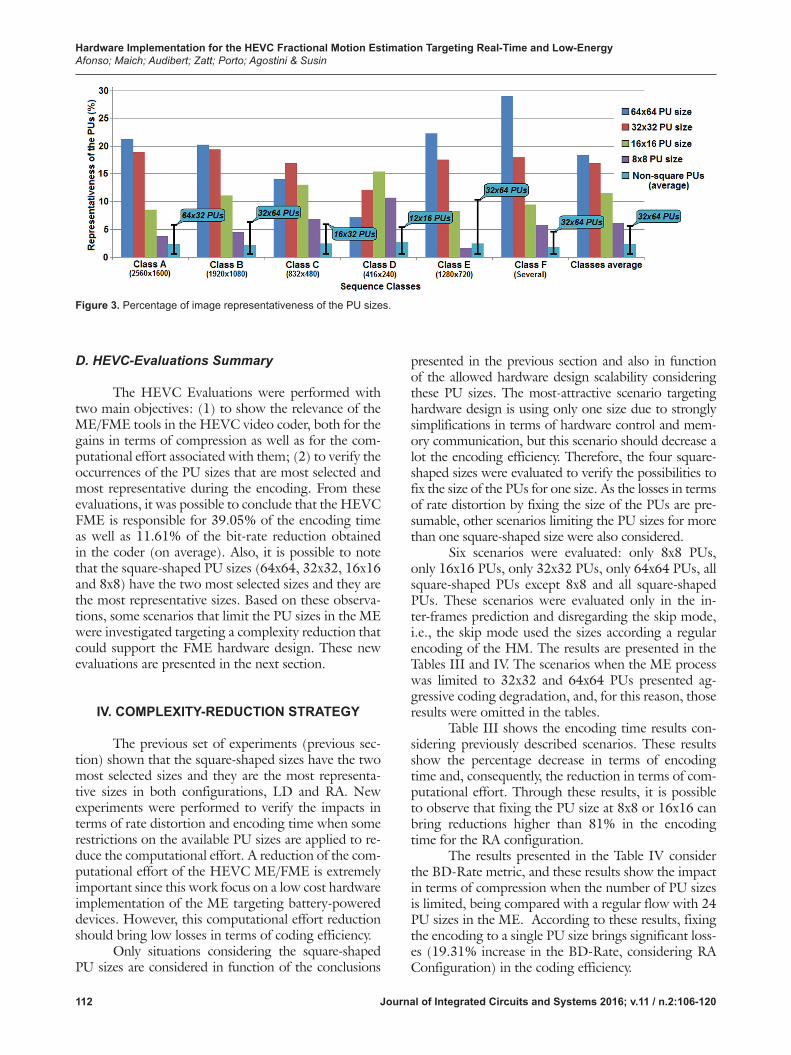
To further evaluate this hypothesis, the data about the selection of the PU sizes were adjusted con-sidering the image representation of each PU size. The concept of representativeness depicts the percentage of pixels that were encoded by each PU size, considering an average of all test conditions. This analysis, as de-picted in Fig. 3, shows that bigger sizes (as 64x64 and 32x32) are more representative in the video sequences, even being less frequent. Fig. 3 presents the PU size representativeness distribution in each sequence class, as well as the average distribution considering all class-es. The values are presented separately for each square-shaped PU size and for the average of the remaining PU sizes (non-square shaped). The overlapped lines in the “Non-square PUs” represent the range that the other PU sizes can reach. As expected, the bigger PU sizes are more important in higher resolutions, while the smaller PU sizes are more important in the lower resolutions.
Figures 2 and 3 show that square-shaped PUs are both frequent and representative when compared to the non-square PUs. Note that 8x8 PU size is the most frequent and the 16x16 PU size is the second most fre-quent, whereas the square-shaped sizes (64x64, 32x32, 16x16, and 8x8) are the most representative sizes. Fur-thermore, the average results are consistent with the results of each sequence class.
In the next subsection, the HEVC-evaluations summary is presented.
It is possible to infer that a simple way to reduce the computational effort is reducing the PU sizes that must be compared in the ME process. However, the real impact in terms of compression and image qual-ity of using some specific PU must be evaluated. To support this idea, the incidence of each PU size in the inter-frames prediction and its representativeness on the frame were investigated. Hence, some simplifica-tions could be proposed and evaluated to obtain a low-er computational effort in the inter-frames prediction. Therefore, the HM code was modified with the aim of extracting those data.
All the sequences and configurations defined by the CTCs were encoded for all classes in the RA and LD configurations. Therefore, 24 test sequences were used according the sequence classes previously men-tioned [15].
Fig. 2 shows the percentage of selection of the PU sizes in the inter-frames prediction in each se-quence class, as well as the average distribution con-sidering all classes. The values are presented separately for each square-shaped PU size (64x64, 32x32, 16x16, and 8x8) and for the average of the remaining PU siz-es (non-square shaped). Notice that the “Non-square PUs” percentage on Fig. 2 presents the average of 20 different PU sizes. These results were generated disre-garding skip blocks for both LD and the RA configu-rations. The overlapped lines in the “Non-square PUs” represent the range that the other PU sizes can reach, where the base of the lines represents the lower value of all PU sizes and the blue balloons in the top of the overlap lines represent the most frequent sizes consid-ering the non-square shaped PUs.
The 8x8 PU size is the most frequently select-ed block size considering an average of the values for all classes. The second most often selected size is the 16x16. Note that the 32x32 and 64x64 PU sizes are poorly selected when compared to the other sizes (fifth and fourteenth more selected sizes only). Fig. 2 also shows that the results of each class are compatible with the average values, i.e., 8x8 and 16x16 PU sizes are
Figure 2. Percentage of selection of the PU sizes.
Hardware Implementation for the HEVC Fractional Motion Estimation Targeting Real-Time and Low-EnergyAfonso; Maich; Audibert; Zatt; Porto; Agostini & Susin
112 Journal of Integrated Circuits and Systems 2016; v.11 / n.2:106-120
D. HEVC-Evaluations Summary
The HEVC Evaluations were performed with two main objectives: (1) to show the relevance of the ME/FME tools in the HEVC video coder, both for the gains in terms of compression as well as for the com-putational effort associated with them; (2) to verify the occurrences of the PU sizes that are most selected and most representative during the encoding. From these evaluations, it was possible to conclude that the HEVC FME is responsible for 39.05% of the encoding time as well as 11.61% of the bit-rate reduction obtained in the coder (on average). Also, it is possible to note that the square-shaped PU sizes (64x64, 32x32, 16x16 and 8x8) have the two most selected sizes and they are the most representative sizes. Based on these observa-tions, some scenarios that limit the PU sizes in the ME were investigated targeting a complexity reduction that could support the FME hardware design. These new evaluations are presented in the next section.
IV. COMPLEXITY-REDUCTION STRATEGY
The previous set of experiments (previous sec-tion) shown that the square-shaped sizes have the two most selected sizes and they are the most representa-tive sizes in both configurations, LD and RA. New experiments were performed to verify the impacts in terms of rate distortion and encoding time when some restrictions on the available PU sizes are applied to re-duce the computational effort. A reduction of the com-putational effort of the HEVC ME/FME is extremely important since this work focus on a low cost hardware implementation of the ME targeting battery-powered devices. However, this computational effort reduction should bring low losses in terms of coding efficiency.
Only situations considering the square-shaped PU sizes are considered in function of the conclusions
presented in the previous section and also in function of the allowed hardware design scalability considering these PU sizes. The most-attractive scenario targeting hardware design is using only one size due to strongly simplifications in terms of hardware control and mem-ory communication, but this scenario should decrease a lot the encoding efficiency. Therefore, the four square-shaped sizes were evaluated to verify the possibilities to fix the size of the PUs for one size. As the losses in terms of rate distortion by fixing the size of the PUs are pre-sumable, other scenarios limiting the PU sizes for more than one square-shaped size were also considered.
Six scenarios were evaluated: only 8x8 PUs, only 16x16 PUs, only 32x32 PUs, only 64x64 PUs, all square-shaped PUs except 8x8 and all square-shaped PUs. These scenarios were evaluated only in the in-ter-frames prediction and disregarding the skip mode, i.e., the skip mode used the sizes according a regular encoding of the HM. The results are presented in the Tables III and IV. The scenarios when the ME process was limited to 32x32 and 64x64 PUs presented ag-gressive coding degradation, and, for this reason, those results were omitted in the tables.
Table III shows the encoding time results con-sidering previously described scenarios. These results show the percentage decrease in terms of encoding time and, consequently, the reduction in terms of com-putational effort. Through these results, it is possible to observe that fixing the PU size at 8x8 or 16x16 can bring reductions higher than 81% in the encoding time for the RA configuration.
The results presented in the Table IV consider the BD-Rate metric, and these results show the impact in terms of compression when the number of PU sizes is limited, being compared with a regular flow with 24 PU sizes in the ME. According to these results, fixing the encoding to a single PU size brings significant loss-es (19.31% increase in the BD-Rate, considering RA Configuration) in the coding efficiency.
Figure 3. Percentage of image representativeness of the PU sizes.

Hardware Implementation for the HEVC Fractional Motion Estimation Targeting Real-Time and Low-EnergyAfonso; Maich; Audibert; Zatt; Porto; Agostini & Susin
113Journal of Integrated Circuits and Systems 2016; v.11 / n.2:106-120
Therefore, although an expressive result in terms of encoding time reduction, the losses in the compression make the strategy of fixing the PU for only one size unacceptable, as presented in Table IV. Similarly, when we fix the PU sizes for the three most representative sizes, the compression losses continue to be important, at least 13.83%, on RA-configuration average.
Nevertheless, considering the four square-shaped PU sizes, the compression losses are about 4%. Although the losses in terms of compression when the number of the PU sizes used in the ME is limited to the square-shaped sizes, the computational effort is drasti-cally reduced (to 1/6 in the ME approximately, from 24 to 4 modes). Since the ME is the most complex module in the encoder, the relevance of this strategy is presumable. Still, the reduction in the total encoding time is higher than 57.9% for any sequence class, as can be seen in the Table III.
This scenario with all square-shaped PU sizes presented the best trade-off for the target application. But other important fact is that this simplification al-lows an efficient hardware design, since a scalable hard-
ware could be designed. This means that one module designed for 8x8 PU size can be reused four times to process a 16x16 PU. Then, this simplification allows a more efficient hardware design, allowing the paral-lelism exploration and a better control of the tradeoff among hardware cost, energy consumption and throughput.
Based on the conclusions presented in this sec-tion, an architecture for the HEVC FME supporting the four square-shaped PU sizes is presented in the next section.
V. FME HARDWARE DESIGN
The proposed architecture (Fig. 8) was designed to perform the FME only at the PU size that present-ed the best IME result. As previously mentioned, the FME can be divided into two main units: (a) the inter-polation; and (b) the search and comparison. This ar-ticle presents an architecture for the FME which is able to perform both the interpolation with quarter-pixel precision and the search and comparison considering
Table III. Percentage decrease in the encoding time with limited PU sizes.
Sequence Classes
LD Configuration (%) RA Configuration (%)
8x8PU size
16x16PU size
Square PU sizes
(except 8x8)
SquarePU sizes
8x8PU size
16x16PU size
Square PU sizes
(except 8x8)
SquarePU sizes
Class A - 2560x1600* – – – – 81.84 85.15 71.04 58.92
Class B - 1920x1080 82.79 86.29 72.37 60.23 81.26 84.14 70.96 60.15
Class C - 832x480 82.98 86.23 70.61 59.69 81.56 84.00 69.40 58.77
Class D - 416x240 82.66 85.70 72.23 60.14 80.68 83.30 69.67 57.97
Class E - 1280x720** 83.58 86.12 70.31 58.42 – – – –
Class F- several 83.09 86.19 70.75 57.97 81.85 84.29 69.64 58.74
Average 83.02 86.10 71.25 59.29 81.44 84.18 70.14 58.91
* Class A is not used with the LD Configuration, according to the CTCs.** Class E is not used with the RA Configuration, according to the CTCs.
Table IV. Percentage increase in BD-Rate with limited PU sizes.
Sequence Classes
LD Configuration (%) RA Configuration (%)
8x8PU size
16x16PU size
Square PU sizes
(except 8x8)
SquarePU sizes
8x8PU size
16x16PU size
Square PU sizes
(except 8x8)
SquarePU sizes
Class A - 2560x1600* – – – – 38.24 18.80 7.19 2.56
Class B - 1920x1080 28.69 21.27 13.59 2.77 25.53 23.69 16.34 2.33
Class C - 832x480 18.82 20.11 16.29 4.31 15.95 17.16 14.07 3.84
Class D - 416x240 14.92 22.34 20.45 5.55 11.66 17.80 16.37 4.30
Class E - 1280x720** 33.67 17.89 8.84 4.49 – – – –
Class F- several 21.45 27.24 22.32 6.10 16.24 19.08 15.21 4.12
Average 23.51 21.77 16.30 4.64 21.52 19.31 13.83 3.43
* Class A is not used with the LD Configuration, according to the CTCs.** Class E is not used with the RA Configuration, according to the CTCs.

Hardware Implementation for the HEVC Fractional Motion Estimation Targeting Real-Time and Low-EnergyAfonso; Maich; Audibert; Zatt; Porto; Agostini & Susin
114 Journal of Integrated Circuits and Systems 2016; v.11 / n.2:106-120
blocks at the fractional positions. The FME hardware design was developed based on the HEVC Main Pro-file and the architecture works with 8x8 blocks to as-semble the bigger square-shaped blocks (16x16, 32x32 and 64x64), reducing the hardware-resource usage. The FME hardware design is presented in the next two subsections. First, the design of the interpolation fil-ters is shown. Finally, the complete FME hardware is presented.
A. Interpolation Filters Design
The interpolation unit uses FIR filters to in-terpolate the luminance samples and a buffer to store some generated samples that are reused in the fil-ters to interpolate other samples. Since interpolation filters have an important cost in terms of hardware, some optimizations were implemented. As previously explained, there are fifteen equations to generate the values of the fractional positions [1]. However, these equations have some similarities that allow algebraic manipulations and the sharing of common sub-expres-sions. Hence, to reduce the hardware cost of the mul-tiplications by constant, they were replaced by shift-adds.
Due to the similarities between the equations, which share the same multiplications by constants in some cases only two different hardware architectures are needed for the filters. Table V shows the constants used in the multiplications according to the fractional positions presented in Section 2. Note that two sets of constants are the same, although in an inverse or-der. Hence, only filter inputs must be changed and the hardware design used in the filters can be the same.
Even though only two hardware designs are needed for the filters, three sets of filters were adopted according to the calculation of fractional positions to obtain the desirable parallelism in the complete FME architecture. Each set of filters is responsible for each set of samples presented in Table V. Then, the three sets of filters are called here Up-type, Middle-type and Down-type, according to the position of the fractional samples related to the samples at integer positions. Fig. 4 shows the respective fractional samples calculated for each one of the three sets of filters.
Architectures with three pipeline stages were de-signed targeting real-time processing for ultra-high res-
olution videos, one considering the Up/Down filters, and another one considering the Middle filters. Figures 5 and 6 presented the Middle and the Up/Down filters, respectively.
The interpolation filters developed in this work are optimized versions of the filter presented in [9]. Basically, these current filters have the following im-provements: (a) treat the rounding error due the use of shift, rather the conventional division; (b) implement a better balance of pipeline according to the processing rate targeted; (c) use a bit width in the adder outputs according to the maximum possible values; and (d) present synthesis for both FPGA and ASIC technol-ogies with energy consumption results for ASIC tech-nology.
It is important to note that the filter inputs (a0-a7) shown in the Figures 5 and 6 are 8-bit wide, considering the luminance values at the integer posi-tions. However, some fractional samples require other
Figure 5. Middle Filter Architecture.
Table V. FIR-filter coefficients defined by the HEVC.
Fractional Positions FIR-Filter Coefficients
ai,j , di,j , ei,j , fi,j , gi,j {–1, 4, –10, 58, 17, –5, 1, 0}
bi,j , hi,j , ii,j , ji,j , ki,j {–1, 4, –11, 40, 40, –11, 4, –1}
ci,j , ni,j , pi,j , qi,j , ri,j {0, 1 , –5, 17, 58, –10, 4, –1}
Figure 4. Fractional samples generated according the filter type.

Hardware Implementation for the HEVC Fractional Motion Estimation Targeting Real-Time and Low-EnergyAfonso; Maich; Audibert; Zatt; Porto; Agostini & Susin
115Journal of Integrated Circuits and Systems 2016; v.11 / n.2:106-120
fractional samples as inputs. The fractional values used as inputs (ai,j, bi,j and ci,j) can present values between -64 and 319 or -96 and 351, depending of the fil-ter type. For this reason, the filter inputs are 10-bit wide. In turn, the filter outputs can change according to the type of filter. The Up/Down filter output is 10-bit wide, while the Middle filter output is 11-bit wide, as shown in the Figures 5 and 6.
In the scope of this work, the fractional positions were also classified according to their positions related to the integer positions. Fig. 7 details the three types of fractional positions. Horizontal-type fractional samples (H-type) are calculated from the integer samples with horizontally-distributed positions in the block. The Vertical-type fractional samples (V-type) are calculat-ed from the integer samples with vertically-distributed
positions in the block. Finally, the Diagonal-type frac-tional samples (D-type) are calculated from the H-type fractional samples previously calculated and they are located diagonally with respect to the integer samples.
B. FME Hardware Architecture
The complete FME architecture, with all the modules needed for both the interpolation and the search and comparison units is shown in Fig. 8.
To interpolate the samples, a scheme able to perform the calculation of an entire line or column of fractional samples per cycle was adopted. Therefore, three sets of nine units of each filter (Up, Middle and Down filters) were used to allow the calculation of 27 fractional samples per cycle, considering each 8x8 block. Note that the FME architecture was designed to work with all square-shaped PU sizes, assembled from the 8x8 PU sizes. By assembling the bigger square-shaped PU sizes from the 8x8 PU sizes, the hardware resources can be saved.
In the Fig. 8, a multiplexer is used to select the 16 samples that must be connected to the filter inputs. These samples can be provided from reference frames stored in an external memory (integer positions with eight bits) or it can be provided from the internal buf-fer (H-type fractional positions), since some calculat-ed fractional samples must be reused in the filters to calculate other fractional positions. The H-type buf-fer stores H-type fractional samples with 10-bit wide.
Figure 6. Up/Down Filter Architecture.
Figure 7. Fractional positions according to the integer samples.
Figure 8. FME Hardware Architecture.

Hardware Implementation for the HEVC Fractional Motion Estimation Targeting Real-Time and Low-EnergyAfonso; Maich; Audibert; Zatt; Porto; Agostini & Susin
116 Journal of Integrated Circuits and Systems 2016; v.11 / n.2:106-120
For the Search and Comparison modules and the SAD Trees, all the fractional samples must have eight bits, including the H-type samples. Hence, a clip operation is needed. This clip operation cannot be performed be-fore the H-type samples are stored in the buffer, since this fact would cause an accumulative error.
The Clip module is applied before the fraction-al samples going to the Search and Comparison Unit. This module is used to maintain the values of the sam-ples between 0 and 255 (8-bit wide), since after the interpolation the fractional samples had an increase in the bit width due to the sum and subtraction oper-ations inside the filters. Basically, negative values are transformed to 0 and values higher than 255 are trans-formed to 255. Values between 0 and 255 continue the same. So, all the fractional samples again have eight bits, like the samples at the integer positions.
Considering an 8x8 block, 432 H-type fraction-al positions must be calculated and stored (27 columns x 16 lines). The H-type buffer stores 16 lines because a border of four horizontal samples above the block and four horizontal samples below the block are needed for the calculation of other fractional samples. Also, 216 V-type fractional positions must be calculated. Finally, H-type samples are used as inputs in the filters to cal-culate the 729 D-type fractional positions. Therefore, 27 fractional samples are calculated per cycle, totalizing 51 cycles to process an 8x8 block (considering that the pipeline of the filters is filled).
As previously mentioned, the 8x8 block that presents the best result in the IME can be compared with other 48 fractional blocks formed from the in-terpolation process. In this work, the Full Search (FS) algorithm is used for the FME, i.e., all the fractional blocks are compared. This decision is based in some facts: (a) Only 48 blocks must be compared; (b) The result is optimal inside the search area, and (c) The de-pendencies of data in the search are eliminated, since half and quarter-pixel blocks are processed in parallel.
Basically, the Search and Comparison have the following modules: SAD Trees, SAD Accumulators, and SAD Comparator, as can be seen in the Fig. 8.
The SAD Trees module allows the SAD (Sum of Absolute Differences) calculation for all fractional blocks formed from the interpolation and it has 12 SAD tree units. Each SAD tree unit is able to calculate the SAD of one fractional block. Basically, the SAD tree unit obtains the differences between the fractional samples of the reference frames (R0-R7) and the in-teger samples of the current block (C0- C7), for each position, as presented in the Fig. 9. After, the results of these subtractions (only the absolute number) are summed. One SAD tree has four pipeline stages and it is able to process an entire line or column (depending on the fractional samples) of the 8x8 block per cycle, since the unit processes the SAD of eight samples in
parallel. As the SAD Trees module has 12 SAD tree units, this module is able to calculate 12 lines of 12 fractional blocks simultaneously.
After the latency of the SAD tree units, the SAD results of the lines or columns must be accumulated in the SAD Accumulator module, since each block has eight lines or columns. Twelve outputs of the SAD trees are connected to 48 accumulators as presented in Fig. 10-a, so that 12 accumulators are selected every eight clock cycles. This way, after 12 cycles, the FME module has the SAD of the six or 12 fractional blocks. Although there are 12 SAD trees, the blocks related with H-type and the V-type fractional samples are cal-culated for each six blocks. In the sequence, the SAD of the blocks related with the D-type fractional samples are calculated for each 12 fractional blocks.
Figure 9. Architecture of one SAD tree.
Figure 10. Simplified architectures: a) SAD Accumulator of one block; b) SAD Comparator of two blocks.

Hardware Implementation for the HEVC Fractional Motion Estimation Targeting Real-Time and Low-EnergyAfonso; Maich; Audibert; Zatt; Porto; Agostini & Susin
117Journal of Integrated Circuits and Systems 2016; v.11 / n.2:106-120
The SAD Trees module is fed three times ac-cording to the interpolation, once for each type of frac-tional samples, as can be seen in the Fig. 11.
It is important to note that the SAD Trees and the SAD Accumulators need 51 cycles to calculate the SAD of the 48 fractional blocks, line after line (or col-umn after column), as the interpolation. The outputs of the accumulator are 20 bit-wide since the SAD of the bigger square-shaped PUs, as the 64x64 PU, can be calculated from 8x8 blocks. Such as the integer samples of the reference frames, the integer samples of the cur-rent block (eight bits) are stored in an external memory and they are accessed every eight samples.
After the calculation of the SAD values for all 48 fractional blocks, these values, and their respective mo-tion vectors, are sent to the SAD Comparator module, as can be seen in the Fig. 8. The SAD comparator uses 48 simplified comparators as presented in Fig. 10-b distributed for six pipeline stages. This module is re-sponsible to compare all blocks simultaneously, two by two, inside the module. The SAD Comparator has six pipeline stages, since for each pipeline stage, half of the motion vectors and SAD values are discarded. During the processing of one of these pipeline stages, the com-parison with the SAD obtained by the IME is per-formed. Then, the SAD Comparator delivers the SAD value and the motion vector of the block that presents the best result between all fractional blocks and the IME after six cycles. It is important to highlight that the motion vectors are stored in an external memory and they are selected according to the fractional blocks. As the SAD comparator module works in parallel with the SAD calculation of the next 8x8 block, this module does not affect the total number of cycles.
Both, the Interpolation and the Search and Comparison modules were integrated to a control unit. This control of the FME architecture was implemented through a state machine. Since the Interpolation re-quires 51 clock cycles to generate the sub-pixel sample values of an 8x8 block after the pipeline is filled, and
the Search and Comparison needs of 51 clock cycles for working including the cycles needed to fill the pipe-line, these FME units can work in parallel.
Basically, the SAD trees are fed with the first fractional samples while the other fractional positions are interpolated. Fig. 11 shows the details of the syn-chronism considering the FME architecture, including an analysis about the number of cycles needed for all FME modules. It is important to note that there are 19 initial cycles to interpolate the H-type fractional sam-ples, including three cycles to fill the pipeline and eight cycles (four cycles after to fill the pipeline and four cy-cles at the right) to interpolate the fractional samples at the border of the 8x8 block. These samples are needed to interpolate other fractional samples.
The first valid results depend on the cycles need-ed in the Interpolation and the Search and Comparison. So, the FME architecture delivers the first valid results considering an 8x8 block in 64 cycles. After these cycles, the results of a new 8x8 block are delivered at each 51 cycles. This number of cycles refers to an 8x8 block size. Besides the 8x8 PUs, the bigger square-shaped PUs can be fragmented into multiple 8x8 blocks. Then, as strat-egy, the composition of bigger PUs through the use of 8x8 PU size was adopted. The number of cycles to pro-cess a square-shaped PU can increase according to the size. For instance, a 16x16 PU size requires 204 cycles to be processed after the pipeline is filled.
VI. SYNTHESIS RESULTS AND COMPARISON
In this section, the results obtained from the de-veloped FME architecture are presented and discussed. The FME architecture was described in VHDL and the synthesis results were generated considering FPGA and ASIC technologies, using the Quartus II Altera Tool [17] and the Cadence RTL Compiler [18], re-spectively. All the results for the FPGA were obtained using the Altera Stratix V 5SGXEA3K2F40C1 device.
Figure 11. Clock cycles distribution to process an 8x8 block.

Hardware Implementation for the HEVC Fractional Motion Estimation Targeting Real-Time and Low-EnergyAfonso; Maich; Audibert; Zatt; Porto; Agostini & Susin
118 Journal of Integrated Circuits and Systems 2016; v.11 / n.2:106-120
Table VI presents the results and related works for the FPGA technology. The developed architecture reaches a maximum frequency of 408.83 MHz. Con-sidering our ME/FME simplifications, the minimal frequency to process UHD 2160p videos at 60 fps is 396.8 MHz. This way, considering the FPGA device, the architecture is able to process 240 fps at HD 1080p and 60 fps at UHD 2160p resolutions when operating at the full speed.
Table VI shows that this work presents high hardware-resource usage when compared with some FPGA designs found in the literature, using 7,092 ALMs (12,031 ALUTs and 13,235 registers). This hardware-resource usage is expected since our work implements a whole FME design. Anyway, the other video coding tools can be integrated on the same de-vice since only 5% of the FPGA device was used.
The works [9] and [10] (previous works) do not implement the search and comparison unit. Al-though both works are able to process UHD 2160p videos at 60fps, this work presents much lower loss-es in terms of compression, with a 4.04% increase in BD-rate, on average. The work [8] is unable to process UHD 2160p videos at 60 fps neither implements a
whole FME design. Furthermore, it has compression losses that are not clearly presented in the paper. When compared with the related work [12] (previous work), this work presents the same throughput and compres-sion losses, while reducing the hardware-resource us-age about 44.22%.
The ASIC hardware results, obtained with the 45nm Nangate standard-cells technology, are detailed in the right-most column of Table VII. The developed architecture uses 148,410 gates to implement the com-plete FME architecture. It is possible to note that our design is able to process UHD 4320p (7680 x 4320 pixels) videos at 30fps at least, since the maximum fre-quency reaches 826.45 MHz. However, we consider that UHD videos require at least 60 fps for a real-time processing. Therefore, we decide to omit the results for this target. Also, our design reaches real-time process-ing of HD 1080p videos with low energy consump-tion, about 4.96mW. The energy consumption results for the UHD 2160p resolution at 60 fps is 15.85mW.
Table VII also present results of some promi-nent HEVC FME related works. The performance re-sults in Table VII show that [8] is unable to process UHD 2160p videos at 60 fps. Despite the work [7]
Table VI. Results and related works for the FPGA technology.
Related Works Pastuszac [8] Afonso [9] Maich [10] Afonso [12] Developed Design
Search and Comparison no no no yes yes
FPGA Technology Arria II GX Stratix III Stratix III Stratix V Stratix V
ALUTs 28,757 4,077* 8,744 17,628 12,031
Registers N.A. 20,408 57,859 28,715 13,235
BD-Rate Increase yes 22.52%** 20.51%** 4.04%** 4.04%**
Freq. 1080p@30fps (MHz) 100 49.6 22.1 49.6 49.6
Freq. 2160p@60fps (MHz) no 396.8 176.8 396.8 396.8*: Partial ALUTs result mentioned in the paper. **: Results using HM13.0 and CTCs.
Table VII. Results and related works for the ASIC technology.
Related Works Diniz [7] Pastuszac [8] He [11] Afonso [12] Developed Design
Search and Comparison no no yes yes yes
ASIC Technology TSMC 150nm TSMC 90nm 65nm* TSMC 65nm Nangate 45nm
Total Area (gates) 30,209 277,074 1,183k 249,153 148,410
SRAM (bits) 1,224 no 19.2k no no
BD-Rate Increase no yes 2.07%** 4.04%*** 4.04%***
1080p@30fpsFreq. (MHz) 78 100 12 49.6 49.6
Power/Voltage N.A. N.A. 6.3mW / 0.7V 8.1mW / 0.72V 4.96mW / 0.9V
2160p@60fpsFreq. (MHz) no no 95 396.8 396.8
Power/Voltage no no 48.3mW / 0.7V 48.67mW / 0.72V 15.85mW / 0.9V*: Library was not mentioned in the paper.**: Results using HM10.0 ***: Results using HM13.0 and CTCs.

Hardware Implementation for the HEVC Fractional Motion Estimation Targeting Real-Time and Low-EnergyAfonso; Maich; Audibert; Zatt; Porto; Agostini & Susin
119Journal of Integrated Circuits and Systems 2016; v.11 / n.2:106-120
demonstrating lower hardware-resource usage than our design, this work developed only the filters of the interpolation unit. To show the relevance of our re-sults in terms of hardware-resource usage, it is possi-ble to see that our result for a complete FME uses less hardware than that used by [8] which implements only the interpolation unit. The works [7] and [8] do not present power-consumption results. When compared with the related work [12] (previous work), this work presents the same throughput and compression losses, while reducing the hardware-resource usage and the energy consumption about 40.4% and 38.8%, respec-tively (1080p@30fps). Considering 2160p@60fps, the energy consumption is reduced about three times.
Considering the presented results, it is possible to conclude that only one published work [11] that is not a previous work presents a complete HEVC FME like the presented in this article, including the interpo-lation and the search and comparison units. The per-formance result obtained by [11] allows the processing of UHD 2160p videos in real time with low energy consumption. However, the work [11] uses a strategy to reduce the complexity of the FME, where the 7 and 8-tap filters used to calculate the quarter-pixel samples in the HEVC were replaced by bilinear filters, as the H.264/AVC standard [2]. Thus, the strategy used by [11] imposes the use of two different hardware designs for FME and Motion Compensation (MC) filtering of the encoder in order to avoid the coding/decoding drifting and its consequent image quality degradation.
In addition, [11] presents an analysis on the compression losses of its complexity-reduction strategy using 11 videos with high and ultra-high resolutions. Therefore, [11] does not use the CTCs nor evaluates its strategy with low resolution videos, which lead to imprecise results in terms of image quality degrada-tion. Considering its analysis, [11] presents 2.07% increase in the BD-Rate, while our work presents an average increase of 4.04% (considering the CTCs). However, when only the five common HD 1080p sequences (Kimono, ParkScene, Cactus, BQTerrace, Bas-ketballDrive) are considered for both works, the com-pression losses are similar. In this scenario, our work presents a 2.55% increase in terms of BD-Rate, while [11] presents 2.35%. Furthermore, our strategy is much wider than the strategy presented by [11] (FME strategy only) since our scheme reduces in 59% the to-tal encoding time and the global energy-consumption (not evaluated here), while the compression losses of [11] do not consider complexity-reduction strategies for IME, which is not plausible (IME is more complex than FME).
The power dissipation presented in [11] is higher than the power dissipation obtained from our hardware design about three times considering 2160p@60fps. In terms of frequency, [11] reaches re-
al-time processing with a lower frequency for UHD resolution due to higher parallelism. However, the ar-chitecture in [11] uses a very large area, which is about eight times larger than ours.
Despite the developed work using an ASIC 45nm and the main related works use 65nm technol-ogy, we use a supply voltage higher than the related works. Furthermore, our hardware and power results are substantially better than the related works.
VII. CONCLUSIONS
This work presented an optimized hardware design for the whole HEVC FME targeting real-time processing for ultra-high resolution videos focusing on battery-powered devices. A detailed study about the state of the art was developed, allowing a solid the-oretical background. Evaluations about HEVC ME/FME shown that the four square-shaped PU sizes have the two most frequently selected sizes and they are the most representative sizes in the encoding process. These observations led us to adopt a complexity reduc-tion strategy based in the use of the four square-shaped PU sizes in the ME. This approach brought a reduc-tion of about 59% in the total encoding time with only 4% increase on BD-Rate. A HEVC FME hardware architecture was developed and the synthesis results for ASIC 45nm technology show that the developed architecture is able to process UHD 2160p videos at 60 fps consuming only 15.85mW and reducing dras-tically the hardware-resource usage when compared to the related works.
ACKNOWLEDGEMENTS
We have a special acknowledgement to CNPq, CAPES and FAPERGS to support this work.
REFERENCES
[1] International Telecommunication Union. Recommendation ITU-T H.265: High efficiency video coding. April, 2013.
[2] International Telecommunication Union. ITU-T Recommen-dation H.264: Advanced video coding for generic audiovisual services. November, 2007.
[3] G. J. Sullivan and T. Wiegand, “Draft requirements for next-generation video coding project,” VCEG-AL96, Geneva, July, 2009.
[4] G. J. Sullivan, et al., “Overview of the High Efficiency Video Coding (HEVC) Standard,” IEEE Transactions on Circuits and Systems for Video Technology, Vol. 22, December, 2012, pp. 1649-1668.
[5] A. Puri, X. Chen and A. Luthra, “Video Coding Using the H.264/MPEG-4 AVC Compression Standard,” Elsevier Sig-nal Processing: Image Communication, No. 19, 2004, pp. 793–849.

Hardware Implementation for the HEVC Fractional Motion Estimation Targeting Real-Time and Low-EnergyAfonso; Maich; Audibert; Zatt; Porto; Agostini & Susin
120 Journal of Integrated Circuits and Systems 2016; v.11 / n.2:106-120
[6] Z. Zhao and P. Liang, “A Statistical Analysis of H.264/AVC FME Mode Reduction,” IEEE Transactions on Circuits and Systems for Video Technology, Vol. 21, No. 1, January, 2011, pp. 53-61.
[7] C. Diniz, M. Shafique, S. Bampi, and J. Henkel, “High throughput interpolation hardware architecture with coarse grained reconfigurable datapaths for HEVC,” in Proceedings of the 20th IEEE International Conference on Image Pro-cessing, 2013, pp. 2091-2095.
[8] G. Pastuszak and M. Trochimiuk, “Architecture design of the high-throughput compensator and interpolator for the H.265/HEVC encoder,” Journal of Real-Time Image Processing, 2014.
[9] V. Afonso, H. Maich, L. Agostini and D. Franco, “Low cost and high throughput FME interpolation for the HEVC emerg-ing video coding standard,” in Proceedings of the 4th Latin American Symposium on Circuits and Systems, 2013.
[10] H. Maich, V. Afonso, D. Franco, B. Zatt, M. Porto and L. Agostini, “High throughput hardware design for the HEVC Fractional Motion Estimation Interpolation Unit,” in Proceed-ings of the 20th IEEE International Conference on Electron-ics Circuits and Systems, 2013.
[11] G. He, D. Zhou, Y. Li, Z. Chen, T. Zhang and S. Goto, “High-Throughput Power-Efficient VLSI Architecture of Frac-tional Motion Estimation for Ultra-HD HEVC Video Encod-ing,” IEEE Transactions on Very Large Scale Integration Systems, 2015.
[12] V. Afonso, H. Maich, L. Audibert, B. Zatt, M. Porto, and L. Agostini, “Memory-Aware and High-Throughput Hardware Design for the HEVC Fractional Motion Estimation,” in Pro-ceedings of the 28th Symposium on Integrated Circuits and Systems Design, 2015.
[13] I. Kim, K. McCann, K. Sugimoto, B. Bross, W. Han and G. Sullivan, High Efficiency Video Coding (HEVC) Test Model 13 (HM13) Encoder Description, JCTVC-O1002, Geneva, October, 2013.
[14] High Efficiency Video Coding (HEVC) Reference Software – HM13.0rc1. Dec., 2014; http://hevc.hhi.fraunhofer.de
[15] F. Bossen, Common Test Conditions and Software Refer-ence Configurations, JCTVC-L1100, Geneva, January, 2013.
[16] G. Bjontegaard, Improvements of the BD-PSNR model, VCEG-AI11, July, 2008.
[17] ALTERA. FPGA CPLD and ASIC from Altera. Altera Web Site. Oct., 2014; www.altera.com
[18] SYNOPSYS. Synopsys.com. Synopsys Web Site. Dec., 2014; www.synopsys.com