hardware guide - iridescentiridescentlearning.org/.../2014/11/biobots-hardware-guide-galileo.pdf ·...
TRANSCRIPT

Hardware GuideFor Intel Galileo
1
2
3
4
5
6
7
8
9
10
inches

2
Contents
Hardware GuideMake your Galileo Blink 3Make your Galileo Blink Some More 10Using Inputs 13Using Motors 22Guide to Debugging 31

Hardware 3
Hardware
1.1: OverviewThe Intel Galileo is a microcontroller which is a small computer that is meant to control other electron-ics. A computer is something you can program to do math or logical sequences. Programming is just how you tell a computer what to do. You can tell your computer “make a game” but it won’t know what that means. You have to go through and tell the computer what to do in a language the computer understands and give it step-by-step instructions.
But, if you learn how to program, you can make your microcontroller do all kinds of things. People have made robots, cool lighting projects, and much more, do a search for ‘arduino projects’ and you’ll see all kinds of cool things. (Arduino is another example of a microcontroller that is used commonly. There are a lot of open source codes and resources available for Arduinos and you can use many of them with your Galileo!)
Learning programming is like learning a new language, however, you have to start simple. This activity is a first start. We will make a light blink on and off on your microcontroller board.
1.2: Installing / Setting UpFollow these three sections to properly install your Galileo and have it communicate with your computer:• Installing Software • Driver Installation• Firmware
Now you are ready to get started!
At this point, plug your Galileo into a power source (Lesson 1, Figure 1), the power light should turn on. Wait a few seconds and the light labeled “usb” will turn on. Once it is turned on, connect the Galileo to the computer using a micro usb cable. Make sure you connect the power before connecting the USB cable.
1: Make your Galileo Blink
Lesson 1 Figure 1

Hardware 4
Hardware
In order to program your Galileo, we are going to use the Arduino program (which can also communicate with your Galileo board). Open the Arduino program. On the top bar go to tools -> board and select Intel Gali-leo (Gen 2 if you are using Gen 2), this tells your computer what type of microcontroller you are using. Then, go to tools -> serial port and make sure something is selected.
Lesson 1 Figure 2
1.3: Basic Programming StructureNow that your Galileo and computer are ready to go, we can start thinking about programming. The Arduino program is something called an IDE or Interactive Development Environment. It is a software that is meant to help you program. Interactive means that you, the user, can interact or use it. Develop-ment is a word which can mean ‘to program’. The Environment means the stuff around your program which can help you. The IDE offers an easier way to connect to the Galileo, highlighting, example codes (Under file->examples) and a lot of other nice things. For our Galileo, we are going to use Arduino IDE. Lets get started!
When you opened this program you should see the following code already written for you:
voidsetup(){//putyoursetupcodehere,torunonce:
}
voidloop(){//putyourmaincodehere,torunrepeatedly:}
Hardware 5
Hardware
These are two functions that are the basic structure of Arduino programming. A function is a piece of code that does something.
The first function is ‘setup’. The word “void” before it just tells you that it doesn’t return anything or give something back. The ‘setup’ function is what the microcontroller knows to do first. Anything you put in be-tween the first two brackets{} will be done first.
The second function is ‘loop’. It also doesn’t return anything. Theloop function happens right afterset-up, and runs over and over, until you reset the microcontroller or load a new program.
Without you telling the microcontroller to do something different, it will run:
setuplooplooplooploop...
That’s how the microcontroller works. If you program something else, it might be different.
The sentences that are after the two forward slashes (//) are called comments. They are used by the programmer to remember what they were doing. The microcontroller completely ignores anything after the two slashes on the same line. It is always good practice to comment in your code, because it is often hard to remember what you were doing, or other people might need to look at your code and figure out what you were trying to do.
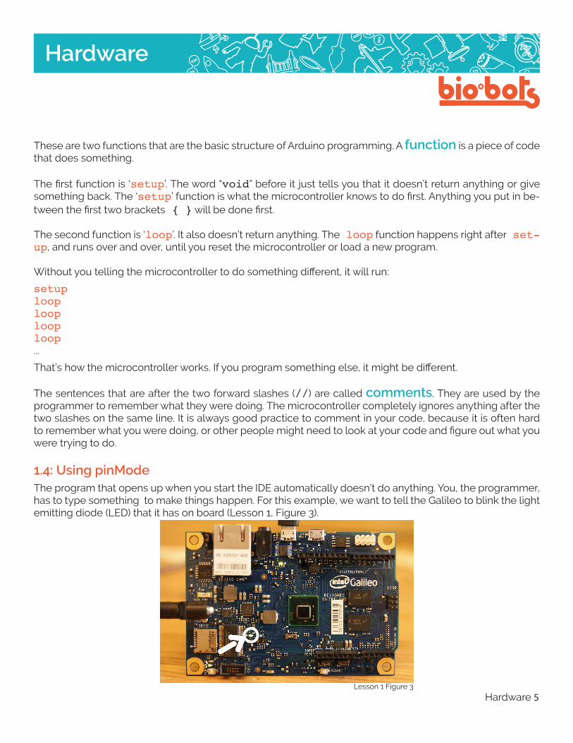
1.4: Using pinModeThe program that opens up when you start the IDE automatically doesn’t do anything. You, the programmer, has to type something to make things happen. For this example, we want to tell the Galileo to blink the light emitting diode (LED) that it has on board (Lesson 1, Figure 3).
Lesson 1 Figure 3

Hardware 6
Hardware
Before you start programming, you have to know a few things. The Galileo is not very smart, you have to type very carefully for it to understand what you want it to do. It has trouble with capitalization, as in it knows what the word ‘OUTPUT’ means, but not the word ‘Output’. It also needs every bracket to match, ev-ery ‘{‘ needs to have a ‘}’ somewhere. Every line of code inside a function needs to end with a semicolon (‘;’), or else the Galileo won’t know where the line ends. Look a the Guide to Debugging for information on how to avoid and resolve these syntax errors.
The microcontroller interacts with the world by using “pins”, (Lesson 1 Figure 4) which are the slots labeled 1, 2, 3, … ,A0, A1, A2,... those are spots where the microcontroller can turn on and off power to, and can read information from.
Lesson 1 Figure 4
The built-in LED is attached to pin 13. We are going to be outputting to that pin, in other words we are writ-ing to that pin.
The way we tell the microcontroller to use Pin 13, the LED, as an output is using a function called “pin-Mode”. It is used like this:
pinMode(13,OUTPUT);
pinMode is the function name. It means that you should assign some pin a certain mode.
‘13’ and ‘OUTPUT’ are arguments. They are numbers/words/characters that give the function some in-formation about what it is going to do. They are separated by a comma, so the microcontroller knows when one argument stops, and another begins. They are surrounded by parentheses, which tells the microcon-troller that this is a function, and what things are the arguments.
13 is the pin number, it can be whatever number pin you want to use. OUTPUT tells the microcontroller what you are going to do with the pin. It has to be in all caps, or the microcontroller won’t know what it is.
The line ends with a semicolon (;), which tells the microcontroller that this line of code is over.
Hardware 7
Hardware
Notice that I wrote a comment after the code I wrote. This helps me know what I was doing when I wrote it, and it makes it easier to come back to the program.
At this point it is a good idea to check for mistakes. A quick way to do that is press the “verify” button which is the checkmark in the upper left-hand corner. This checks your code and sees if there are any very large mistakes. Those errors will show up in the bottom console screen, where it will let you know if there is anything wrong. Since you’ve only wrote one line of code, the problem is most likely there.
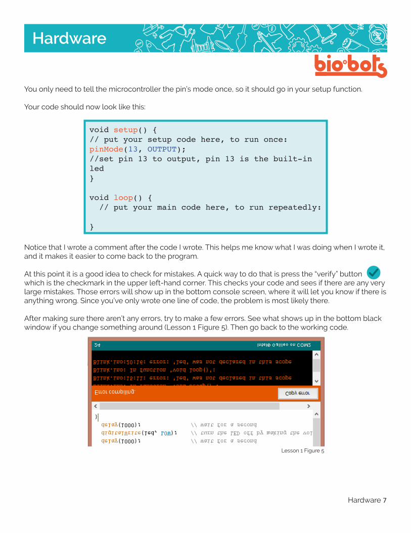
After making sure there aren’t any errors, try to make a few errors. See what shows up in the bottom black window if you change something around (Lesson 1 Figure 5). Then go back to the working code.
You only need to tell the microcontroller the pin’s mode once, so it should go in your setup function.
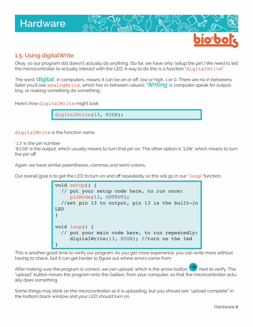
Your code should now look like this:
voidsetup(){//putyoursetupcodehere,torunonce:pinMode(13,OUTPUT);//setpin13tooutput,pin13isthebuilt-inled}
voidloop(){//putyourmaincodehere,torunrepeatedly:}
Lesson 1 Figure 5
Hardware 8
Hardware
1.5: Using digitalWriteOkay, so our program still doesn’t actually do anything. (So far, we have only ‘setup the pin’.) We need to tell the microcontroller to actually interact with the LED. A way to do this is a function “digitalWrite”.
The word ‘digital’, in computers, means it can be on or off, low or high, 1 or 0. There are no in betweens (later you’ll see analogWrite, which has in-between values). ‘Writing’ is computer-speak for output-ting, or making something do something.
Here’s how digitalWrite might look:
digitalWrite(13,HIGH);
digitalWrite is the function name.
‘13’ is the pin number‘HIGH’ is the output, which usually means to turn that pin on. The other option is ‘LOW’, which means to turn the pin off.
Again, we have similar parentheses, commas and semi-colons.
Our overall goal is to get the LED to turn on and off repeatedly so this will go in our “loop” function.
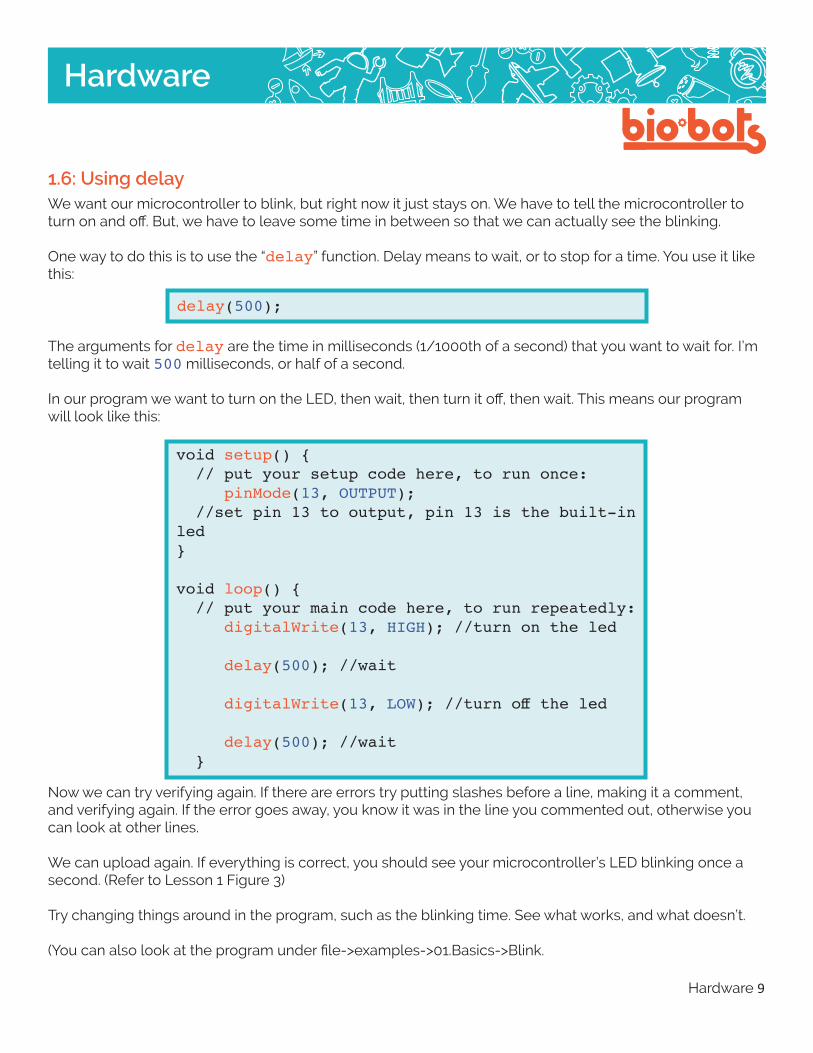
voidsetup(){//putyoursetupcodehere,torunonce: pinMode(13,OUTPUT);//setpin13tooutput,pin13isthebuilt-inLED}
voidloop(){//putyourmaincodehere,torunrepeatedly: digitalWrite(13,HIGH);//turnontheled}
This is another good time to verify our program. As you get more experience, you can write more without having to check, but it can get harder to figure out where errors come from.
After making sure the program is correct, we can upload, which is the arrow button next to verify. The “upload” button moves the program onto the Galileo, from your computer, so that the microcontroller actu-ally does something.
Some things may blink on the microcontroller as it is uploading, but you should see “upload complete” in the bottom black window and your LED should turn on.
Hardware 9
Hardware
1.6: Using delayWe want our microcontroller to blink, but right now it just stays on. We have to tell the microcontroller to turn on and off. But, we have to leave some time in between so that we can actually see the blinking.
One way to do this is to use the “delay” function. Delay means to wait, or to stop for a time. You use it like this:
delay(500);
The arguments for delay are the time in milliseconds (1/1000th of a second) that you want to wait for. I’m telling it to wait 500 milliseconds, or half of a second.
In our program we want to turn on the LED, then wait, then turn it off, then wait. This means our program will look like this:
voidsetup(){//putyoursetupcodehere,torunonce: pinMode(13,OUTPUT);//setpin13tooutput,pin13isthebuilt-inled}
voidloop(){//putyourmaincodehere,torunrepeatedly: digitalWrite(13,HIGH);//turnontheled
delay(500);//wait
digitalWrite(13,LOW);//turnofftheled
delay(500);//wait}
Now we can try verifying again. If there are errors try putting slashes before a line, making it a comment, and verifying again. If the error goes away, you know it was in the line you commented out, otherwise you can look at other lines.
We can upload again. If everything is correct, you should see your microcontroller’s LED blinking once a second. (Refer to Lesson 1 Figure 3)
Try changing things around in the program, such as the blinking time. See what works, and what doesn’t.
(You can also look at the program under file->examples->01.Basics->Blink.

Hardware 10
Hardware
2.1: External OutputsWhen using a Galileo, the chip itself doesn’t have a lot ways to interact with the outside world. In order to make your Galileo do some more interesting things, you have to be able to connect external outputs.
‘External’ means it is separate from the microcontroller. The opposite word is ‘internal’. In the previous lesson, you made the ‘internal’ LED (on the physical Galileo board) blink.
‘Output’ is something that the microcontroller can tell to do something. You can see an output light up, move, or do something else. Outputs include motors, LEDs, and light bulbs. It is the opposite of an input, which tells the microcontroller information based upon something in the outside world.
2.2: Connecting an LEDWe have made an onboard (internal) LED light on and off on our Galileo, but now we have to start going ‘off the board’. This means we have to provide a path from the microcontroller to the external LED and back. If we were going to move cars back and forth, we would build a road. If we were moving water, we would make a pipe. We are moving electricity so we need a path made of metal, which electricity can travel across. Metal is a great conductor like you learned in Circuitry Lessons.
An easy way to connect electronic components is to use rubber-coated electrical wire. The rubber prevents electricity going in a way we don’t expect. And the metal wire conducts electricity across it.
To connect things we first have to take a piece of wire, however long makes sense to you, and remove the rubber from the ends of both sides. Take off enough to work with easily. This is called “stripping the wire”.
We are going to use the Blink program again (If you lost it or don’t have it, open file->examples->01. Basic->Blink). This program communicates through pin 13. That means we have to insert our wire into pin 13 (Lesson 2, Figure 1).
2: Make your Galileo Blink Some More
Lesson 2 Figure 1
metalwires
rubber

Hardware 11
Hardware
From pin 13, it should go to the LED and back to the Galileo. In order to go back to the Galileo, we have to use one of the pins labeled “GND” (Lesson 2, Figure 2). GND stands for ‘Ground’, which in electronics means a place where electricity likes to go back to. We then need to get another wire, and insert it into a GND pin.
Lesson 2 Figure 2
With two wires in our Galileo, first make sure they are not touching. (Tape one or both down, if you are having trouble.) Once, we are sure of that, we can connect our Galileo to power and to the computer, and upload the blink program.
Check that the onboard LED is blinking. If not, there is a problem with the program or the connection be-tween the Galileo and the computer. If that LED is blinking, we can try connecting our external LED. Hold or clip one side of the LED to one wire, and the other side of the LED to the other wire. Try flipping the LED around by switching the wires.
Do neither ways work? Check a few things. If you move the wire in pin 13 to the pin labeled 5V (Lesson 2, Fig-ure 3) and try the LED both ways, does it work? 5V is always on. If it isn’t working, double check your Galileo is plugged in, then try another LED, because maybe your first LED is broken.
Lesson 2 Figure 3
There may be other problems with your hardware, maybe a wire is broken. Maybe the wires are rusty and aren’t connecting correctly. Maybe wires are accidently touching. Maybe you have the wrong pin. Try a few things. Trying different configurations to make this work is called “hardware debugging”.
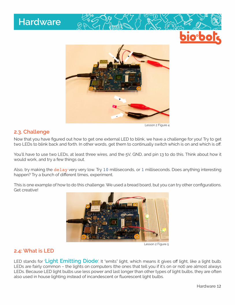
The LED only works one way, look carefully at the leads, one is longer than the other, write down which one connects to ground. There may also be an indent on one side of the LED, also write down which way that is facing (Lesson 2, Figure 4).
Hardware 12
Hardware
Lesson 2 Figure 4
2.3. ChallengeNow that you have figured out how to get one external LED to blink, we have a challenge for you! Try to get two LEDs to blink back and forth. In other words, get them to continually switch which is on and which is off.
You’ll have to use two LEDs, at least three wires, and the 5V, GND, and pin 13 to do this. Think about how it would work, and try a few things out.
Also, try making the delay very very low. Try 10 milliseconds, or 1 milliseconds. Does anything interesting happen? Try a bunch of different times, experiment.
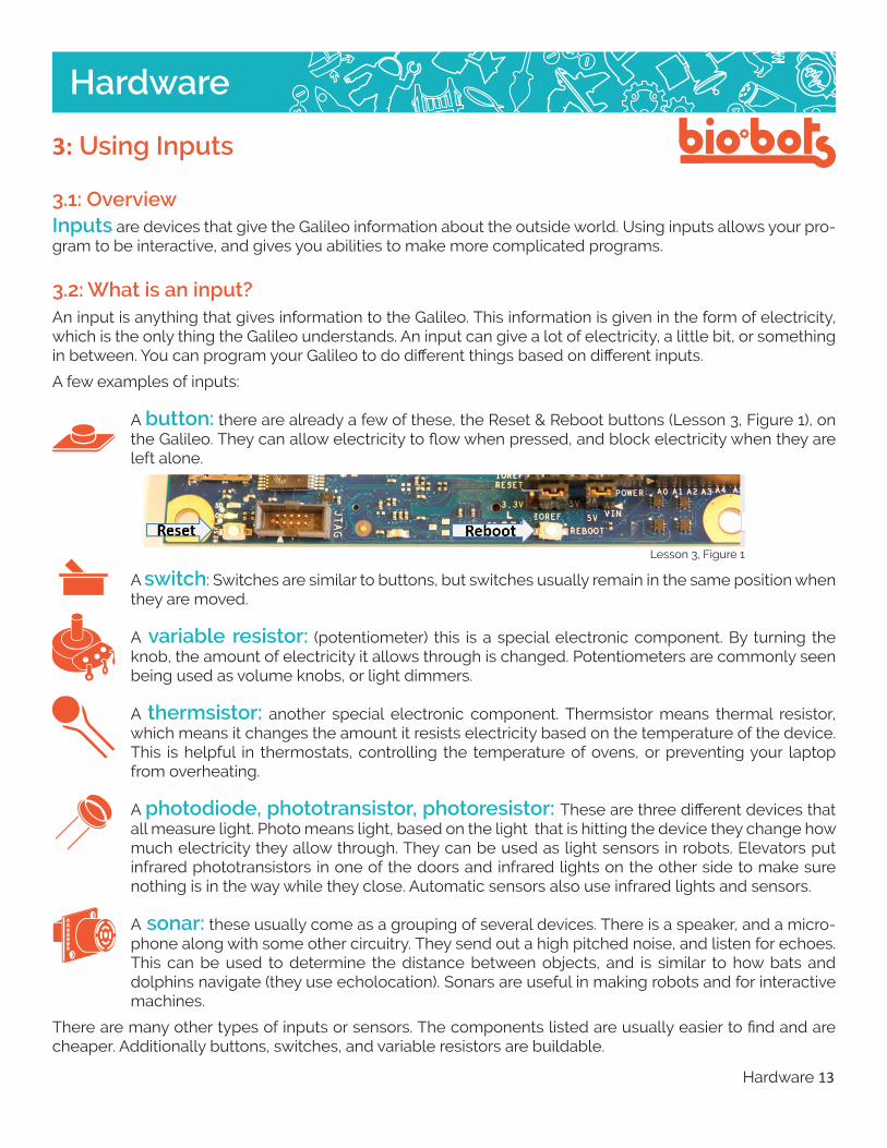
This is one example of how to do this challenge. We used a bread board, but you can try other configurations. Get creative!
2.4: What is LED
LED stands for ‘Light Emitting Diode’. It “emits” light, which means it gives off light, like a light bulb. LEDs are fairly common – the lights on computers (the ones that tell you if it’s on or not) are almost always LEDs. Because LED light bulbs use less power and last longer than other types of light bulbs, they are often also used in house lighting instead of incandescent or fluorescent light bulbs.
Lesson 2 Figure 5
Hardware 13
Hardware
3.1: OverviewInputs are devices that give the Galileo information about the outside world. Using inputs allows your pro-gram to be interactive, and gives you abilities to make more complicated programs.
3.2: What is an input?An input is anything that gives information to the Galileo. This information is given in the form of electricity, which is the only thing the Galileo understands. An input can give a lot of electricity, a little bit, or something in between. You can program your Galileo to do different things based on different inputs.
A few examples of inputs:
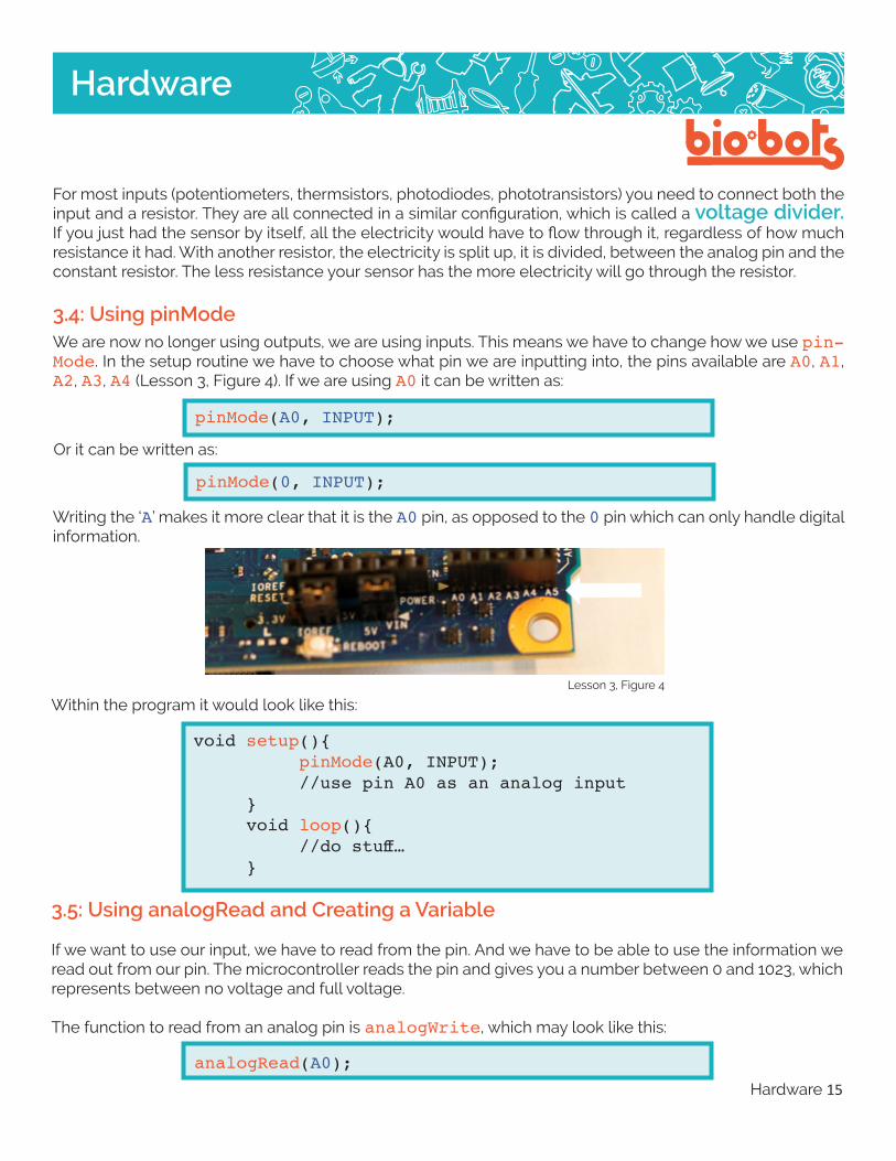
A button: there are already a few of these, the Reset & Reboot buttons (Lesson 3, Figure 1), on the Galileo. They can allow electricity to flow when pressed, and block electricity when they are left alone.
A switch: Switches are similar to buttons, but switches usually remain in the same position when they are moved.
A variable resistor: (potentiometer) this is a special electronic component. By turning the knob, the amount of electricity it allows through is changed. Potentiometers are commonly seen being used as volume knobs, or light dimmers.
A thermsistor: another special electronic component. Thermsistor means thermal resistor, which means it changes the amount it resists electricity based on the temperature of the device. This is helpful in thermostats, controlling the temperature of ovens, or preventing your laptop from overheating.
A photodiode, phototransistor, photoresistor: These are three different devices that all measure light. Photo means light, based on the light that is hitting the device they change how much electricity they allow through. They can be used as light sensors in robots. Elevators put infrared phototransistors in one of the doors and infrared lights on the other side to make sure nothing is in the way while they close. Automatic sensors also use infrared lights and sensors.
A sonar: these usually come as a grouping of several devices. There is a speaker, and a micro-phone along with some other circuitry. They send out a high pitched noise, and listen for echoes. This can be used to determine the distance between objects, and is similar to how bats and dolphins navigate (they use echolocation). Sonars are useful in making robots and for interactive machines.
There are many other types of inputs or sensors. The components listed are usually easier to find and are cheaper. Additionally buttons, switches, and variable resistors are buildable.
3: Using Inputs
Lesson 3, Figure 1

Hardware 14
Hardware
3.3: Ways to Wire Up InputsButtons A button or switch can be made by simply using any two pieces of metal and touching them together, but they can be made in many shapes and sizes. The button can be placed between 5V and an analog input pin (A0 for example). For a more reliable button, it can be connected like in the figure below.
Try pressing the button. Does it do anything? Try different combinations of the button to see how it works.
Lesson 3, Figure 2
Potentiometers normally have the same layout, with three places to connect wires (Lesson 3, Ficure 3).
5V
GND
Button
Lesson 3, Figure 3
A0
5V
GND
Potentiometer
Resistor
Resistor
A0
Hardware 15
Hardware
For most inputs (potentiometers, thermsistors, photodiodes, phototransistors) you need to connect both the input and a resistor. They are all connected in a similar configuration, which is called a voltage divider. If you just had the sensor by itself, all the electricity would have to flow through it, regardless of how much resistance it had. With another resistor, the electricity is split up, it is divided, between the analog pin and the constant resistor. The less resistance your sensor has the more electricity will go through the resistor.
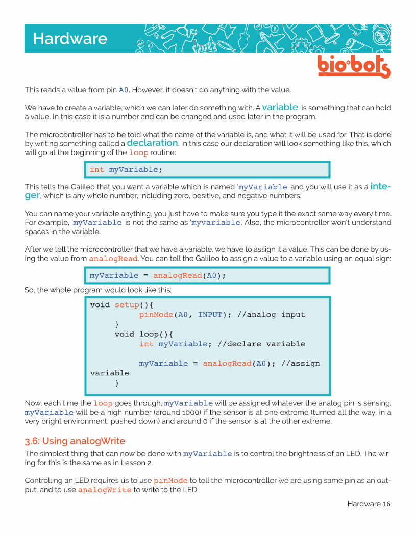
3.4: Using pinModeWe are now no longer using outputs, we are using inputs. This means we have to change how we use pin-Mode. In the setup routine we have to choose what pin we are inputting into, the pins available are A0, A1, A2, A3, A4 (Lesson 3, Figure 4). If we are using A0 it can be written as:
pinMode(A0,INPUT);
Or it can be written as:
pinMode(0,INPUT);
Writing the ‘A’ makes it more clear that it is the A0 pin, as opposed to the 0 pin which can only handle digital information.
Lesson 3, Figure 4
Within the program it would look like this:
voidsetup(){ pinMode(A0,INPUT); //usepinA0asananaloginput } voidloop(){ //dostuff… }
3.5: Using analogRead and Creating a Variable
If we want to use our input, we have to read from the pin. And we have to be able to use the information we read out from our pin. The microcontroller reads the pin and gives you a number between 0 and 1023, which represents between no voltage and full voltage.
The function to read from an analog pin is analogWrite, which may look like this:
analogRead(A0);
Hardware 16
Hardware
This reads a value from pin A0. However, it doesn’t do anything with the value.
We have to create a variable, which we can later do something with. A variable is something that can hold a value. In this case it is a number and can be changed and used later in the program.
The microcontroller has to be told what the name of the variable is, and what it will be used for. That is done by writing something called a declaration. In this case our declaration will look something like this, which will go at the beginning of the loop routine:
intmyVariable;
This tells the Galileo that you want a variable which is named ‘myVariable’ and you will use it as a inte-ger, which is any whole number, including zero, positive, and negative numbers.
You can name your variable anything, you just have to make sure you type it the exact same way every time. For example, ‘myVariable’ is not the same as ‘myvariable’. Also, the microcontroller won’t understand spaces in the variable.
After we tell the microcontroller that we have a variable, we have to assign it a value. This can be done by us-ing the value from analogRead. You can tell the Galileo to assign a value to a variable using an equal sign:
myVariable=analogRead(A0);
So, the whole program would look like this:
voidsetup(){ pinMode(A0,INPUT);//analoginput } voidloop(){ intmyVariable;//declarevariable
myVariable=analogRead(A0);//assignvariable }
Now, each time the loop goes through, myVariable will be assigned whatever the analog pin is sensing. myVariable will be a high number (around 1000) if the sensor is at one extreme (turned all the way, in a very bright environment, pushed down) and around 0 if the sensor is at the other extreme.
3.6: Using analogWriteThe simplest thing that can now be done with myVariable is to control the brightness of an LED. The wir-ing for this is the same as in Lesson 2.
Controlling an LED requires us to use pinMode to tell the microcontroller we are using same pin as an out-put, and to use analogWrite to write to the LED.
Hardware 17
Hardware
analogWrite(myVariable,3);
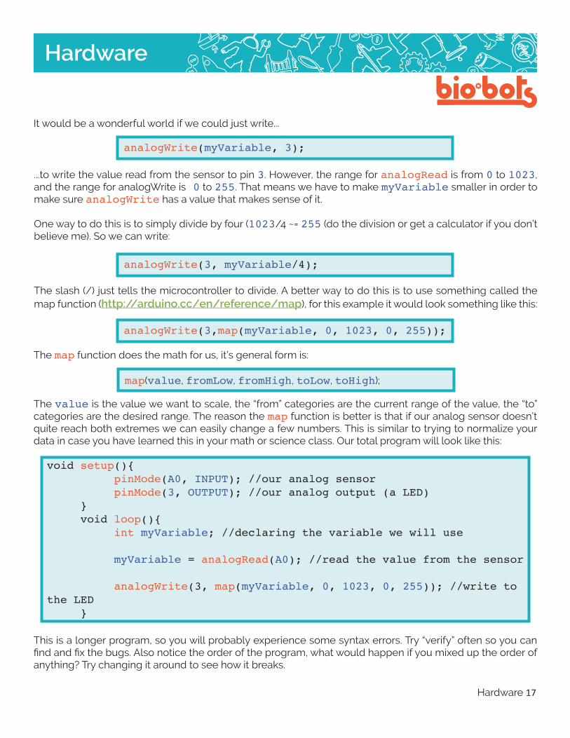
...to write the value read from the sensor to pin 3. However, the range for analogRead is from 0 to 1023, and the range for analogWrite is0 to 255. That means we have to make myVariable smaller in order to make sure analogWrite has a value that makes sense of it.
One way to do this is to simply divide by four (1023/4 ~= 255 (do the division or get a calculator if you don’t believe me). So we can write:
analogWrite(3,myVariable/4);
The slash (/) just tells the microcontroller to divide. A better way to do this is to use something called the map function (http://arduino.cc/en/reference/map), for this example it would look something like this:
analogWrite(3,map(myVariable,0,1023,0,255));
The map function does the math for us, it’s general form is:
map(value, fromLow, fromHigh, toLow, toHigh);
It would be a wonderful world if we could just write...
The value is the value we want to scale, the “from” categories are the current range of the value, the “to” categories are the desired range. The reason the map function is better is that if our analog sensor doesn’t quite reach both extremes we can easily change a few numbers. This is similar to trying to normalize your data in case you have learned this in your math or science class. Our total program will look like this:
voidsetup(){ pinMode(A0,INPUT);//ouranalogsensor pinMode(3,OUTPUT);//ouranalogoutput(aLED) } voidloop(){ intmyVariable;//declaringthevariablewewilluse
myVariable=analogRead(A0);//readthevaluefromthesensor
analogWrite(3,map(myVariable,0,1023,0,255));//writetotheLED }
This is a longer program, so you will probably experience some syntax errors. Try “verify” often so you can find and fix the bugs. Also notice the order of the program, what would happen if you mixed up the order of anything? Try changing it around to see how it breaks.

Hardware 18
Hardware
3.7 Using an input to do something
An input allows a person to interact with the Galileo. To explore inputs, we can start playing and messing with them. This is one suggestion for a project using inputs:
Make a musical instrument!
First, wire up your input so you can see the LED change if you interact with it. I started with a photodiode for my project.
In order to hear something, you have to make a speaker. If you happen to have computer speakers, you can try hooking alligator clips to different parts of the bands, and connecting them to where your LED goes (you can remove the LED). You might hear an annoying pitched noise, which is a good sign!
I didn’t have a speaker ready, so I made one. Loop rubber coated electrical wire in a small circle about twenty times (~1 in diameter). Strip the two ends of the wire, and leave them pointed outward, so you can connect to them. Get a plastic cup and two magnets, place one magnet on the inside of the cup, on the bottom. Place the other magnet underneath the cup, so the magnets stick to each other through the cup. Tape the loop of the wire to the outside bottom of the cup, so that the magnets are in the center of the loop. Connect one side of the wire to GND on your Galileo board, and the other to your output pin. When you upload the input program (above), you should hear a high pitched noise. That means it’s working!
Try interacting with your input (i.e. shining light on the photodiode). Does the sound change? It should!
This gave me a little more variety in the sounds I produced. Try things to see if they make an interesting musi-cal instrument. My final loop function looked liked this:
voidloop(){//putyourmaincodehere,torunrepeatedly:intavalue;//Analogvaluereadfrompinintscaledvalue;//valueafterscaling(dependsonyourinput)avalue=analogRead(motorin)+analogRead(lightin);//addthevaluesfromthemotorandthediode
Serial.println(avalue);//printoutthatvaluetotheserialmonitor,thisisformakingsuretheanaloginputisworking
//continuedonnextpage------>
I also messed with the delay, to make the noise more interesting, I added this line to the end of loop:
delay(map(avalue,0,1024+1024,0,100);
Hardware 19
Hardware
I changed the amount of light going to the photodiode to change the noise coming out the speaker. Play around!
3.8: Using serial (optional)
If you have time or want to learn more about microcontrollers, the serial library is a good way to get more out of your microcontroller.
In our analog sensor program, we assumed our sensor would go all the way from 0 to 1023. However, this is generally not the case, sensors are often not as sensitive as we would like. In our program, we have no real way of telling how sensitive it is, and our LED may not be lighting up as bright or dim as much as we really want.
The serial library is a way to see the actual numbers the microcontroller is using, and to see exactly what it is reading from the pin. This can also be helpful for seeing if the sensor isn’t working at all. The word serial has to do with how the Galileo sends information back to the computer, which is via a serial port. A library is a collection of code someone else has written, which makes our jobs easier.
The microcontroller needs to be told that we are using serial, which means we have to tell it to beginning in setup:
scaledvalue=map(avalue,0,1024+1024,0,254);//Scaletheoutputappropiately,Iguessedandcheckedtomakethesoundmoresensitive.analogWrite(out,scaledvalue);//writethescaledvaluetotheoutputpin
delay(map(avalue,0,1024+1024,0,100);
}
The number, 9600, tells the microcontroller the data rate of the serial, which has to be a certain number. 9600 should be the number you use, until you get into super-advanced microcontroller stuff.
Then, we want to get information to print. In loop we can put commands such as:
Serial.print(“hello”);//printhello! Serial.println(“hey”);//printheyandstartanewline Serial.print(myVariable);//printthevalueofmyvariable Serial.print(“\n”);//printanewline
voidsetup(){ Serial.begin(9600); }
Hardware 20
Hardware
Notice that things without quotations have to be variables, while things with them will just be printed as words or text. The backslash chracter tells the microcontroller it is a special character such as tab, new line, or another thing (see this table: http://msdn.microsoft.com/en-us/library/h21280bw%28v=vs.80%29.aspx although not all of these are implemented in Galileo).
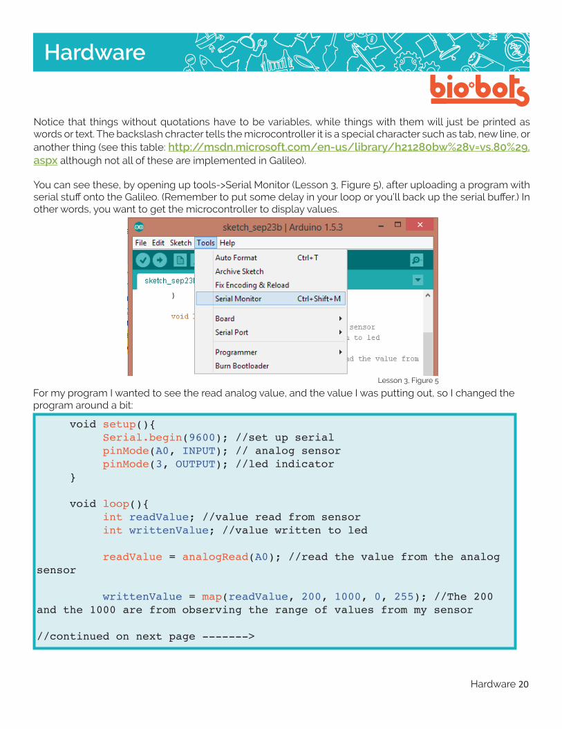
You can see these, by opening up tools->Serial Monitor (Lesson 3, Figure 5), after uploading a program with serial stuff onto the Galileo. (Remember to put some delay in your loop or you’ll back up the serial buffer.) In other words, you want to get the microcontroller to display values.
Lesson 3, Figure 5
For my program I wanted to see the read analog value, and the value I was putting out, so I changed the program around a bit:
voidsetup(){ Serial.begin(9600);//setupserial pinMode(A0,INPUT);//analogsensor pinMode(3,OUTPUT);//ledindicator }
voidloop(){ intreadValue;//valuereadfromsensor intwrittenValue;//valuewrittentoled
readValue=analogRead(A0);//readthevaluefromtheanalogsensor
writtenValue=map(readValue,200,1000,0,255);//The200andthe1000arefromobservingtherangeofvaluesfrommysensor
//continuedonnextpage------->

Hardware 21
Hardware
The program is a lot longer, but it gives nicely formatted data to the serial monitor.
And finally, this is what your musical instrument might look like (Lesson 3, Figure 6):
Lesson 3, Figure 6
Serial.print(readValue);//outputthereadvalue Serial.print(“\t”);//putatabbetweenthevaluestomakeiteasiertoread Serial.print(writtenValue);//outputthewrittenvalue Serial.print(“\n”);//Writeanewline
analogWrite(3,writtenValue);//writetotheled
delay(100);//delayabit }

Hardware 22
Hardware
4.1: What is a motorWe are going to be working with electric motors. Electric motors convert electricity into mechanical movement, generally by spinning in a circle. Motors are used in robots, printers, electric bicycles, factory machinery, electric cars basically anything that moves and is powered by electricity.
Motors exploit a property of magnetism. By running electricity through a wire, a magnetic field is created. Motors loop wires thousands of times so that the magnetic field is a lot stronger than it would be with just one wire. Magnets can push or pull things – they can create a force on something metal or magnetic. If you arrange several wire loops in a circle and put something metal in the middle, you can apply electricity, caus-ing the the metal thing to spin. The spinning thing can be used as the spinning part of the motor. Look back at the resources in the Circuits & Motors lessons for help.
The important thing to remember when making robots is not to know exactly what is happening inside the motor, but how to make the motor what you want to do.
In order to use motors with the Galileo, we have to use something called a motor shield. In the micro-processor world, a shield is a separate chip which allows you to do more with your Galileo, instead of wiring up your own complicated circuit. The motor shield’s purpose is to allow a separate power supply to be used for the motor, and to make moving the motor backwards and forwards easier. A separate power supply is needed because motors use a lot more power than the Galileo can supply by itself.
The maximum electricity a motor will use is usually labeled as a stall current, small motors usually have stall current of around 2Amps. The maximum the Galileo can supply before breaking is around 0.3Amps.
4.2: Installing the Motor LibraryIn order to control a motor in the way we want to do, it is much easier to make the microprocessor program do a lot of the work for us. In programming there are things called libraries, which contain a lot of code that someone else has written. Libraries allow us to simply tell something to “go forward”, instead of worrying about all the things required.
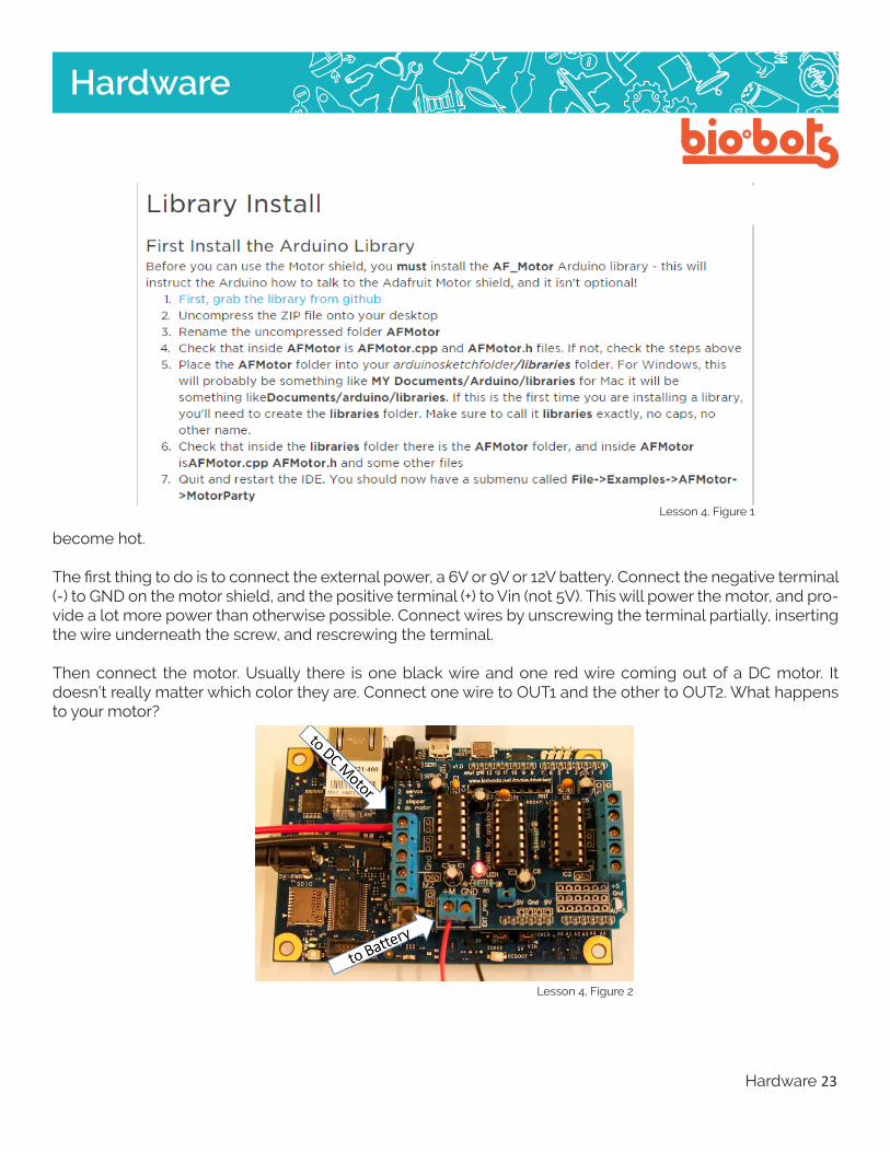
The motor shield that is most commonly used is the Adafruit motor shield. If you’re not sure what motor shield you have, it is most likely the adafruit. There are different layouts for the chip, and perhaps different labels, use your best judgement, and don’t turn it on until you double checked it. Adafruit was nice and wrote their own library for their motor shield, which is available here: https://learn.adafruit.com/adafruit-mo-tor-shield/library-install (Lesson 4, Figure 1, next page)
4.3: Wiring up a DC MotorA DC motor is simple and the most common type of electric motor. DC motors can spin in both directions, and the speed can be changed. DC motors usually spin very fast, but often do not have the torque (power) to turn anything significant or heavy. Gears, or gear boxes, are often used in order to lower the speed and increase the torque. Using a DC motor without any gearing can cause the motor to burn out, and become unusable. Turn off/unplug the motor quickly if it is on but cannot turn. Be careful, because the motor will
4: Using Motors
Hardware 23
Hardware
become hot.
The first thing to do is to connect the external power, a 6V or 9V or 12V battery. Connect the negative terminal (-) to GND on the motor shield, and the positive terminal (+) to Vin (not 5V). This will power the motor, and pro-vide a lot more power than otherwise possible. Connect wires by unscrewing the terminal partially, inserting the wire underneath the screw, and rescrewing the terminal.
Then connect the motor. Usually there is one black wire and one red wire coming out of a DC motor. It doesn’t really matter which color they are. Connect one wire to OUT1 and the other to OUT2. What happens to your motor?
Lesson 4, Figure 2
Lesson 4, Figure 1

Hardware 24
Hardware
Lesson 4, Figure 3
If you want to write your motor program, so you can decide what the motor does, you’ll have to go through some steps.
The first thing you’ll need to do to control a motor is to include the library. At the beginning of your program, before void setup, you have to write:
#include<AFMotor.h>
This tells the Galileo that you are using the Adafruit Motor library, so it knows what the functions you are us-ing are. This will save you from having to write your own functions.
Then you have to tell the Galileo the name of your motor, and where it is connected:
AF_DCMotormymotor(1);
4.4: Controlling a DC Motor
If you are unsure of your wiring, or want to have a test code running, adafruit has example code written, which should show up in the adafruit-Adafruit-Motor-Shield-library under a file called MotorTest.pde. (Les-son 4, Figure 3) You can see some of the functions used in running a motor. Running this should cause the motor to run back and forth repeatedly.

Hardware 25
Hardware
motor.setSpeed(125);
This commands tells the Galileo what speed to run the motor at. The argument can be any number between 0 and 255. This command is just like using analogWrite, it just changes because motors are treated slightly different by the Galileo. This does tell the motor to move.
So, if we want to just go forward our loop function looks like this:
voidloop(){ motor.run(FORWARD);//preparetogoforward
motor.setSpeed(125); //go at around halfspeed
}
Test this program, to make sure your motor goes forward correctly. To make the motor stop we can tell the Galileo this:
motor.run(RELEASE);
The word “RELEASE” just means to stop the motor, to release it. Note that there is no need to set the speed, it’s stopped. We can now make the motor go forward for one second, stop for one second, and repeat:
mymotor is the name of the motor. This can be anything, as long as you keep it the same every time you use it in the program. 1 is the motor number, there should be labels M1, M2, M3, and M4 on the chip. If not, OUT1 and OUT2 should correspond to motor 1. (OUT3 and OUT4 are for motor 2).
First let’s write a basic program that moves the motor back and forth. In setup, you don’t have to write any-thing. Doing something in setup may be helpful if you want the motor to do something once, before starting the loop. But, since we just want to go back and forth, there is no need for setup.
In loop, we want to do two things: make the motor go forward, then make the motor go backwards. In or-der to not break the motor, we should probably tell it to: go forward, stop, go backwards, stop. Motors don’t always like to change direction without stopping in between.
To go forward, we have to use two commands:
motor.run(FORWARD);
This command tells the Galileo that we are going to go forwards with the motor. It does not tell the motor to move, though.

Hardware 26
Hardware
After telling the Galileo that we want to go backwards, we have to set the speed. Our total program, forward, stop, back, stop, looks like this:
voidsetup(){ }
voidloop(){
motor.run(FORWARD); motor.setSpeed(125);//halfspeed delay(1000);//goforwardfor1second
motor.run(RELEASE); delay(500);//stopforhalfasecond
motor.run(BACKWARD); motor.setSpeed(255);//fullspeedbackwards delay(1000);//gobackwardsforasecond
motor.run(RELEASE); delay(500);//stopforhalfasecond }
voidloop(){
motor.run(FORWARD); //prepare to goforward motor.setSpeed(125); //go around halfspeed delay(1000);//goforwardfor1second(1000milliseconds
motor.run(RELEASE);//stopthemotor delay(1000); //stop the motor for 1second }
Again, test this program to make sure it works.
The last thing we need is to tell the motor to go backwards. We tell the Galileo that we want to go backwards by typing:
motor.run(BACKWARD);

Hardware 27
Hardware
For your robot, you can use inputs to control the speed of the motor, and how long the motor runs for, using any of the techniques you used in Lesson 3. You can also have your motor control your robot using a speci-fied pattern, just by controlling speeds and delay times. Experiment!
4.5: Wiring a Servo MotorServo motors are good motors to use for creating robots for several reasons. One being that they can be small, inexpensive and require less power than a DC motor, and two because they are very easy to control using the Galileo. Unlike the DC motor which is able to continually rotate for 360 degrees, most servos only rotate 180 degrees but are able to be controlled and programmed very easily to move in very precise ways. So, if you are looking to give your robot more specific or detailed movements, the servo motor is your better bet.
When connecting the servo motor notice that there are three wires. These can be various colors (my servo has a red, black and yellow wire) but each color is important to note and goes to a specific spot on the Galileo board. Just like with the DC motor there is a positive (+) and negative (-/GND) but with the servo there is one extra wire, that is the signal or command wire. Typically the power or positive wire is red, which will connect to the 5V or Vin pin. The GND wire will usually be black or brown and you will connect that wire anywhere on the Galileo board marked GND. The signal wire can be yellow, orange or white. This wire will need to be con-nected to any of the digital pins numbered 0 to 13 (remember not the pins starting with A which are analog).
When connecting to the Galileo board you may have to play around with the configuration to find out the correct placements. If you want to test to see if your servo is working you can place your GND pin in the cor-rect place and put your power pin in 5V, the servo should ‘jump’ rotating a degree or two just for a second. This means it has power and wants to move, now you just need to tell it what to do. If there is a plug at the end of the three wires on your servo motor, don’t worry. Just plug in a wire into each pin in the plug and con-nect that wire to the appropriate pin on the Galileo board. (Lesson 4, Figure 5)
Lesson 4, Figure 4

Hardware 28
Hardware
Servo motors do not require as much power as a DC motor so unless you are powering more than one mo-tor a motor shield will not be needed. (Leson 4, Figure 6, 7)
Lesson 4, Figure 5
Lesson 4, Figure 6
Lesson 4, Figure 7
4.6: Running a Servo Motor
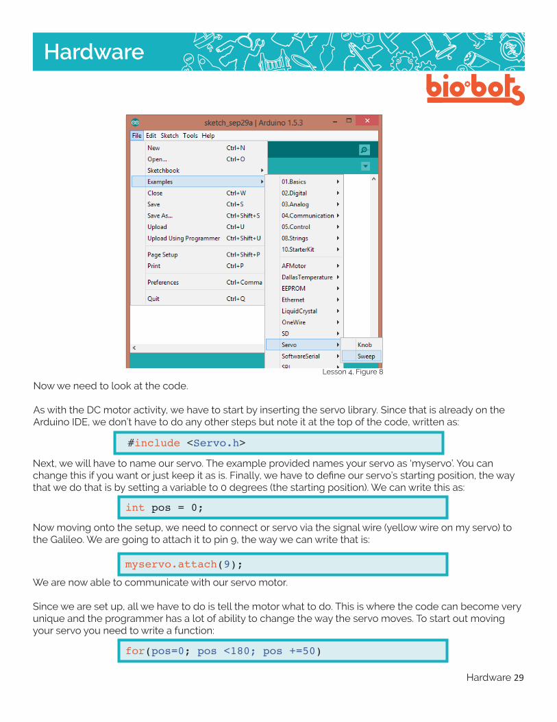
Once you have wired your servo motor it’s time to start programming and get it moving. In order to do this we are going to look at some pre written coded in a library. On the Arduino IDE click File -->Examples →-->Servo-->Sweep (Lesson 4, Figure 8).
Hardware 29
Hardware
Lesson 4, Figure 8
Now we need to look at the code.
As with the DC motor activity, we have to start by inserting the servo library. Since that is already on the Arduino IDE, we don’t have to do any other steps but note it at the top of the code, written as:
#include<Servo.h>
Next, we will have to name our servo. The example provided names your servo as ‘myservo’. You can change this if you want or just keep it as is. Finally, we have to define our servo’s starting position, the way that we do that is by setting a variable to 0 degrees (the starting position). We can write this as:
intpos=0;
Now moving onto the setup, we need to connect or servo via the signal wire (yellow wire on my servo) to the Galileo. We are going to attach it to pin 9, the way we can write that is:
myservo.attach(9);
We are now able to communicate with our servo motor.
Since we are set up, all we have to do is tell the motor what to do. This is where the code can become very unique and the programmer has a lot of ability to change the way the servo moves. To start out moving your servo you need to write a function:
for(pos=0;pos<180;pos+=50)

Hardware 30
Hardware
This is the first function in the Sweep example. The pos=0 is the position we are starting from which in this case we wrote as 0 degrees. The second part is telling the motor to move a total of 180 degrees. Now we need to tell it to stop. We can write that as:
myservo.write(pos);delay(15);
This part tells the motor to stop and wait for a total of 15 milliseconds.
To tell the motor to go move back the other direction, we have to change it’s starting position from 0 de-grees to where we left it 180 degrees. That is written like this:
for(pos=180;pos>=1;pos-=1)
ChallengePlay around with the Sweep code, how could you make the motor go faster? Change the delay and de-grees of movement. Think about how you would want your robot to move, how can you reflect the move-ments you want to make through this code?
Lesson 4, Figure 9

Hardware 31
Hardware
What is debugging?Debugging is the process of removing and fixing problems in computer programming. It is often the longest and most difficult part of creating a computer program, and requires skill, experience, and patience. A lot of patience.
Legend has it, the word came from working on old computers. Back in the 50’s computers were the size of rooms, and problems could occur if moths got stuck in the wiring. The debugger was a person who went into the room and cleaned out all the moths. Nowadays, you will just have to check your code and also look carefully at your hardware to make sure things are connected properly. Most likely, you won’t find any moths!
Types of ErrorsThere are three general types of problems you can face working with your microcontroller.
Hardware Errors Hopefully this is limited to your microcontroller not being plugged in. Hardware errors are problems arising from the physical wiring and connections between the microcontroller, your computer, and other external components.
Syntax Errors Errors that cause the computer to not understand your code. A missing semicolon, or a wrong number of parentheses or brackets are common syntax errors. Usually these will be caught by the compiler when you press verify.
Logical Errors These are not only the most common type of errors, they are the hardest to fix! Yay. A logical error is not something the computer or microcontroller will notice, but will cause your program to not behave correctly. Examples include writing formulas wrong, or writing things out of order.
Dealing with Hardware ErrorsPrevention Catastrophic hardware errors are when your microcontroller breaks completely. This could occur if the microcontroller short-circuits, or if it is overcharged. Prevent short circuiting by keeping your microcontroller away from exposed metal, and storing it in the anti-static bag, or surrounded by insulators, such as wood. Don’t place directly on plastic, or things that might give you a static shock, don’t wrap your desk in shiny wrapping paper, even if it is festive.
Overcharging occurs when you have external components that aren’t interacting correctly with the micro-controller. Make sure you understand what your external components are doing, and how they do it. Double-check your wiring, make sure wires aren’t touching eaching or move around, and ask someone to look at it, consult your instructor. You can plug an lLED into where your microcontroller would be connected. If the LED breaks, or is very bright, something’s wrong.
The most common hardware problems are caused by something not being plugged in correctly. If you have trouble remembering everything, write a checklist, checklists are extremely useful, pilots use them, which reduces accidents incredibly.
Guide to Debuggingwith the Intel Galileo

Hardware 32
Hardware
Diagnosing If your microcontroller is not plugged in, your computer will not be able to communicate with it. This may show up as tools->serial port being grayed out, or the message “transfer incomplete” will show up in your console after pressing “upload”. If you see these try:
• Unplugging and replugging in your microcontroller• Resetting your microcontroller• Rebooting your microcontroller
You may have to wait a minute or two after any of these fixes to see if they work.
Dealing with Syntax ErrorsPrevention Syntax errors are easy to make, typos and missed semicolons are very common. Verifying your code often will help you to know if you made any syntax errors. If you write all your code at once, it will be harder to figure out where the error is, and it is more likely there are more than one. Experience will help, as you get used to ending with a semicolon and matching parentheses.
Diagnosing Usually syntax errors will be caught by the compiler. When you press “verify”, an error will appear in the bottom console.
11:1:error:expected‘;’before‘}’token
There is a missing semicolon, which the compiler noticed at line 11, character 1. The line number of your cursor is displayed in the bottom-left of the IDE. The actual error was on line 9, but the compiler doesn’t notice until a bracket occurs.
9:24:error:expected‘)’before‘;’token
There is a missing closing parenthesis, noticed at line 9, character 24. Usually this error will have the right line number, and the IDE highlights matching parentheses, which is helpful.
9:20:error:‘HIG’wasnotdeclaredinthisscope
The compiler does not know what ‘HIG’ is, at line 9, character 20. This is usually a typo. If ‘HIG’ was a variable you created, make sure it is declared properly at the beginning of your function or program. Maybe it’s missing a field type (int, char, double, long, void).
If you’re not sure where the error is coming from, try commenting out a line, and see if the error goes away. If it did, you know which line is wrong. You comment out a line by adding two forward slashes ‘//’ to the beginning of the line.
Dealing with Logical ErrorsPrevention Logical errors are usually caused by programmer mistakes, or if you don’t exactly know how your program should work. Good programming practice helps prevent these errors.
• Make code readable This means using empty lines to separate code, indenting blocks of code. Name variables, functions, and anything with understandable names, not ‘a’, ‘b’, but something like, ‘myspeed’, ‘forwardspeed’. It is important to keep your style consistent. You can use tools-
Hardware 33
Hardware
>AutoFormat to make your code look nicer.
• Use comments Start by writing comments after every line of code. As you gain more experience, use comments for anything weird, potentially confusing, or a problem area.
• Don’t write your program all at once Break your program into smaller, testable blocks. Make sure you can tell if a part of it is working. If you know each part is working, the only type of errors will be found while putting them together, which is a lot less.
• Test often - Not sure how a part of your code should work? Make a separate program to test it. Look at similar examples using the internet, or the built-in examples (file->examples).
• Write it out - Write out, by hand, how the program is supposed to work. Put each part in a box, and connect the parts with arrows.
Diagnosing - Logical errors are hard to find. If your program just doesn’t work right, even if it uploads fine. Some approaches to find logical errors:
• Write it out again - Go through how it’s supposed to work again, does it make sense? Does the program look the same?
• Comment out a problem line - Try to see if a specific line is causing a problem. What hap-pens, when you remove some line?
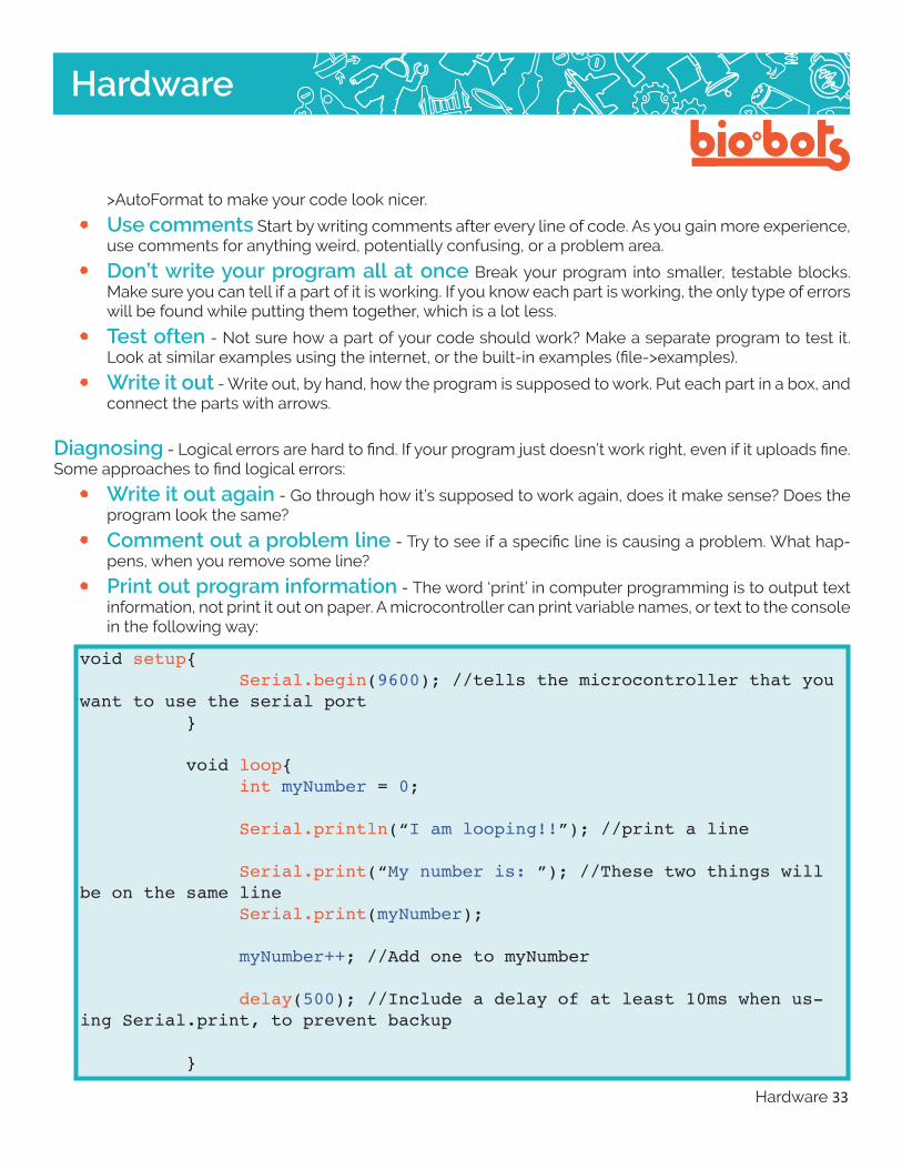
• Print out program information - The word ‘print’ in computer programming is to output text information, not print it out on paper. A microcontroller can print variable names, or text to the console in the following way:
voidsetup{ Serial.begin(9600);//tellsthemicrocontrollerthatyouwanttousetheserialport }
voidloop{ intmyNumber=0;
Serial.println(“Iamlooping!!”);//printaline
Serial.print(“Mynumberis:”);//Thesetwothingswillbeonthesameline Serial.print(myNumber);
myNumber++;//AddonetomyNumber
delay(500);//Includeadelayofatleast10mswhenus-ingSerial.print,topreventbackup
}

Hardware 34
Hardware
This is useful to tell if the numbers you are using are wrong, or acting oddly. Print out important numbers, if they are wrong, look into intermediate numbers. Or if that number is from an input, see if the input is correctly hooked up.