hardness and tensile properties of fe–p based alloys made through powder forging technique
TRANSCRIPT
A
twoMfsaFcso©
K
1
td(fgfidaaipcc
0d
Materials Science and Engineering A 479 (2008) 164–170
Hardness and tensile properties of Fe–P based alloys madethrough powder forging technique
Jiten Das a,∗, K. Chandra b, P.S. Misra b, B. Sarma a
a Defence Metallurgical Research Laboratory, Post Office: Kanchanbagh, Hyderabad 500058, Indiab Metallurgical and Materials Engineering Department, Indian Institute of Technology Roorkee, Roorkee 247667, India
Received 29 August 2006; received in revised form 13 June 2007; accepted 13 June 2007
bstract
High density Fe–P binary, Fe–P–Cr ternary as well as Fe–P–Cr–Si quaternary alloys were made using a hot powder forging technique. Inhis process mild steel encapsulated powders were hot forged into slabs, hot rolled and annealed to relieve the residual stresses. These alloysere characterized in terms of microstructure, porosity content/densification, hardness and tensile properties. Densification as high as 98.9%f theoretical density has been realized. Hot powder forging using channel die showed better densification than that obtained using flat die.icrostructures of these alloys consist of single-phase ferrite only. Rolled and annealed microstructure showed lesser porosity content than the
orged and homogenized one. Phosphorous causes more hardening of ferrite than silicon in solid solution with iron. Alloys containing 0.35 wt%P,uch as Fe–0.35P, Fe–0.35P–0.35Cr and Fe–0.35P–0.35Cr–1Si alloys showed very high ductility with low work hardening coefficient. As forgednd hot rolled Fe–0.35P alloy showed very high elongation and it improved further on annealing. Alloys containing 0.7wt%P, such as Fe–0.7P,
e–0.7P–0.7Cr and Fe–0.7P–0.7Cr–1Si alloys showed very high strength. However, they showed limited ductility with higher work hardeningoefficient. It was observed in this present investigation that, the alloying addition, such as Si and Cr to Fe–P based alloys caused increase intrength associated with the reduction in ductility. Alloys developed in the present investigation were capable of hot/cold working to very thin gagef sheets and wires. 2007 Elsevier B.V. All rights reserved.fopcfs[
mHrha
eywords: Hot powder forging; Fe–P based alloys
. Introduction
The main feature of powder metallurgical manufacturingechnique is its ability to produce net/near net shape componentsirectly and thereby eliminate complex machining sequencesand its associated material loss) and joining processes [1]. Inact any form and shape can be achieved by powder metallur-ical process. It is now so established that the properties of thenal part can be tailored by alloy design, impurity, process andensity controls. It is increasingly becoming energy efficientnd economic due to improved manufacturing technique and thebility to employ cheaper grade powders (e.g. water atomizedron powder). Despite these advantages powder metallurgical
arts will continue to face stiff competition from their wroughtounterparts unless it can demonstrate equivalent performanceharacteristics at a sustainable competitive cost. Density is by∗ Corresponding author. Tel.: +91 9989178700; fax: +91 4024344535.E-mail address: [email protected] (J. Das).
tatpwdf
921-5093/$ – see front matter © 2007 Elsevier B.V. All rights reserved.oi:10.1016/j.msea.2007.06.030
ar the most important parameter in this context. As the densityf powder metallurgical parts increase, physical and mechanicalroperties improve and at a near full density the properties areomparable with their wrought counterparts. It is apparent there-ore, that a strategy for powder metallurgy substitution can onlyucceed if appropriate densification is in place at reasonable cost1].
Near full density pure Fe P/M parts can be very easilyanufactured using conventional powder metallurgical process.owever, pure iron P/M parts have very low strength. Si alloying
educes compressibility of powders. Therefore, achievement ofigh density Fe–Si alloy is a very challenging task. Moreover,ddition of very high amount of Si will render the alloy brit-le. It was observed that partial replacement of Si by a smallmount of P will activate sintering process in Fe–Si alloys byhe formation of low melting eutectic phase with iron. Phos-
horous also helps carrying alloy constituents into iron matrixhich are otherwise sluggish to diffuse. P significantly improvesuctility and strength of Fe–P based alloys [2]. Cr improvesormability of Fe–P based alloys [3]. It is therefore, realized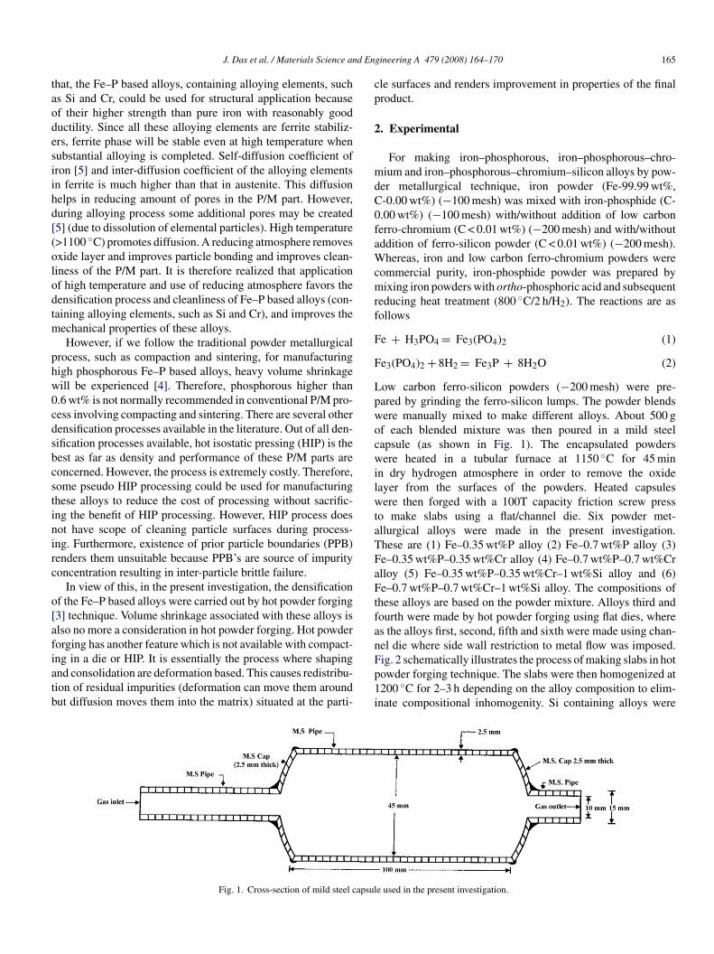
d En
taodesiihd[(olodtm
phw0cdsbcstinirc
o[afiatb
cp
2
mdC0faWcmrf
F
F
LpwocwilwtaTFaFtfan
J. Das et al. / Materials Science an
hat, the Fe–P based alloys, containing alloying elements, suchs Si and Cr, could be used for structural application becausef their higher strength than pure iron with reasonably gooductility. Since all these alloying elements are ferrite stabiliz-rs, ferrite phase will be stable even at high temperature whenubstantial alloying is completed. Self-diffusion coefficient ofron [5] and inter-diffusion coefficient of the alloying elementsn ferrite is much higher than that in austenite. This diffusionelps in reducing amount of pores in the P/M part. However,uring alloying process some additional pores may be created5] (due to dissolution of elemental particles). High temperature>1100 ◦C) promotes diffusion. A reducing atmosphere removesxide layer and improves particle bonding and improves clean-iness of the P/M part. It is therefore realized that applicationf high temperature and use of reducing atmosphere favors theensification process and cleanliness of Fe–P based alloys (con-aining alloying elements, such as Si and Cr), and improves the
echanical properties of these alloys.However, if we follow the traditional powder metallurgical
rocess, such as compaction and sintering, for manufacturingigh phosphorous Fe–P based alloys, heavy volume shrinkageill be experienced [4]. Therefore, phosphorous higher than.6 wt% is not normally recommended in conventional P/M pro-ess involving compacting and sintering. There are several otherensification processes available in the literature. Out of all den-ification processes available, hot isostatic pressing (HIP) is theest as far as density and performance of these P/M parts areoncerned. However, the process is extremely costly. Therefore,ome pseudo HIP processing could be used for manufacturinghese alloys to reduce the cost of processing without sacrific-ng the benefit of HIP processing. However, HIP process doesot have scope of cleaning particle surfaces during process-ng. Furthermore, existence of prior particle boundaries (PPB)enders them unsuitable because PPB’s are source of impurityoncentration resulting in inter-particle brittle failure.
In view of this, in the present investigation, the densificationf the Fe–P based alloys were carried out by hot powder forging3] technique. Volume shrinkage associated with these alloys islso no more a consideration in hot powder forging. Hot powderorging has another feature which is not available with compact-
ng in a die or HIP. It is essentially the process where shapingnd consolidation are deformation based. This causes redistribu-ion of residual impurities (deformation can move them aroundut diffusion moves them into the matrix) situated at the parti-Fp1i
Fig. 1. Cross-section of mild steel capsul
gineering A 479 (2008) 164–170 165
le surfaces and renders improvement in properties of the finalroduct.
. Experimental
For making iron–phosphorous, iron–phosphorous–chro-ium and iron–phosphorous–chromium–silicon alloys by pow-
er metallurgical technique, iron powder (Fe-99.99 wt%,-0.00 wt%) (−100 mesh) was mixed with iron-phosphide (C-.00 wt%) (−100 mesh) with/without addition of low carbonerro-chromium (C < 0.01 wt%) (−200 mesh) and with/withoutddition of ferro-silicon powder (C < 0.01 wt%) (−200 mesh).
hereas, iron and low carbon ferro-chromium powders wereommercial purity, iron-phosphide powder was prepared byixing iron powders with ortho-phosphoric acid and subsequent
educing heat treatment (800 ◦C/2 h/H2). The reactions are asollows
e + H3PO4 = Fe3(PO4)2 (1)
e3(PO4)2 + 8H2 = Fe3P + 8H2O (2)
ow carbon ferro-silicon powders (−200 mesh) were pre-ared by grinding the ferro-silicon lumps. The powder blendsere manually mixed to make different alloys. About 500 gf each blended mixture was then poured in a mild steelapsule (as shown in Fig. 1). The encapsulated powdersere heated in a tubular furnace at 1150 ◦C for 45 min
n dry hydrogen atmosphere in order to remove the oxideayer from the surfaces of the powders. Heated capsulesere then forged with a 100T capacity friction screw press
o make slabs using a flat/channel die. Six powder met-llurgical alloys were made in the present investigation.hese are (1) Fe–0.35 wt%P alloy (2) Fe–0.7 wt%P alloy (3)e–0.35 wt%P–0.35 wt%Cr alloy (4) Fe–0.7 wt%P–0.7 wt%Crlloy (5) Fe–0.35 wt%P–0.35 wt%Cr–1 wt%Si alloy and (6)e–0.7 wt%P–0.7 wt%Cr–1 wt%Si alloy. The compositions of
hese alloys are based on the powder mixture. Alloys third andourth were made by hot powder forging using flat dies, wheres the alloys first, second, fifth and sixth were made using chan-el die where side wall restriction to metal flow was imposed.
ig. 2 schematically illustrates the process of making slabs in hotowder forging technique. The slabs were then homogenized at200 ◦C for 2–3 h depending on the alloy composition to elim-nate compositional inhomogenity. Si containing alloys weree used in the present investigation.
166 J. Das et al. / Materials Science and Engineering A 479 (2008) 164–170
n of s
hforsm
vt
TC
M
FFFFFF
Fig. 2. Schematic diagram illustrating the productio
eated for 3 h whereas alloys without Si content were heatedor 2 h. Because diffusion of Si in iron is much slower than the
ther alloying elements. The mild steel encapsulation was thenemoved by machining. The slabs, after removal of mild steelkin, were hot rolled using flat roll and section roll at ∼900 ◦C toake thin sheets and wires, respectively. Rolling was carried outrgpa
able 1alculated volume percentage of porosities of the alloys
aterial As forged density(g/cc)
Rolled and annealeddensity (g/cc)
e–0.35P 7.6 7.7e–0.7P 7.4 7.5e–0.35P–0.35Cr 7.4 7.5e–0.7P–0.7Cr 7 7.1e–0.35P–0.35Cr–1Si 7.4 7.5e–0.7P–0.7Cr–1Si 7.2 7.4
lab by hot forging of encapsulated powder mixture.
ery slowly at ∼900 ◦C with 0.1 mm thickness/diameter reduc-ion per pass. The rolling was done using small laboratory scale
olling mill with 10 cm roll diameter. Where as 20 passes wereiven for making thin wires, almost 30–35 passes were given forroducing thin sheets. The sheets and wires were then vacuumnnealed at 950 ◦C for 40 min to relieve the residual stresses. AllTheoreticaldensity (g/cc)
Porosity in forgedslabs (vol%)
Porosity in rolled andannealed sheets(vol%)
7.784 2.4 1.17.696 3.8 2.57.780 5.0 3.67.690 9.0 7.77.600 2.6 1.37.520 4.3 1.6
d En
tdb
roid
ais
oaaptv
w
F(ai(f
J. Das et al. / Materials Science an
he samples prepared this way were characterized in terms ofensity, microstructure, hardness, tensile properties as detailedelow.
Density of the forged and homogenized slabs as well asolled and annealed sheets was determined by dividing massf the specimens with the volume of the specimens. The spec-mens were fully dipped in water. Volumes of specimens wereetermined from the volume of water displaced by them.
Homogenized slabs as well as hot rolled and annealed sheetsnd wires were subjected to metallographic examinations. Thisncludes volume percentage of porosity and grain size mea-urements. The microstructures were taken at the cross-section
oTa
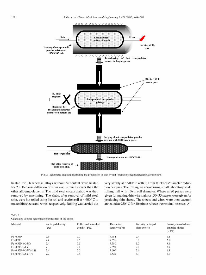
ig. 3. Porosity distribution of the flat die forged alloys, such as (a) porosity 6 voFe–0.7P–0.7Cr alloy forged and homogenized), (e) porosity 3 vol% (Fe–0.35P–0lloy rolled and annealed) as well as channel die forged alloys, such as (b) porosity 5 vol% (Fe–0.7P–0.7Cr–1Si alloy forged and homogenized), (f) porosity 4 vol%Fe–0.7P–0.7Cr–1Si alloy rolled and annealed) before and after hot rolling and anneaorged samples in as forged and homogenized condition. Significant reduction of por
gineering A 479 (2008) 164–170 167
f the as forged and homogenized slabs as well as rolled andnnealed sheets and wires. Cross-section for sheet in this case islong short transverse direction. Calculated volume percentageorosities (density of the specimen × 100/pore free density ofhe specimen) matched with the metallographically measuredolume percentage porosities.
Hardness of the hot rolled and annealed sheets were measuredith Vicker’s hardness tester using 10 kg load.
For tensile testing samples were either punched out of sheetr wires were directly tested using Hounsfeld tensile tester.he tensile testing were carried out at room temperature withcross head speed 1 mm/min. Gauge length of the specimens
l% (Fe–0.35P–0.35Cr alloy forged and homogenized), (c) porosity 10 vol%.35Cr alloy rolled and annealed) and (g) porosity 7 vol% (Fe–0.7P–0.7Cr
ty 5 vol% (Fe–0.35P–0.35Cr–1Si alloy forged and homogenized), (d) poros-(Fe–0.35P–0.35Cr–1Si alloy rolled and annealed) and (h) porosity 3.5 vol%
ling treatment. Channel die forged samples showed lesser porosity than flat dieosity of the samples observed after rolling and annealing treatment.
1 and E
w1
3
mp
vpmw
F(oa
68 J. Das et al. / Materials Science
as 20 mm. Gauge diameter of the tensile sample (wires) wasmm.
. Results and discussions
Volume percentage porosities were estimated from theeasured density of the specimens. These estimated volume
ercentage of porosities are recorded in Table 1. In order to
tsrw
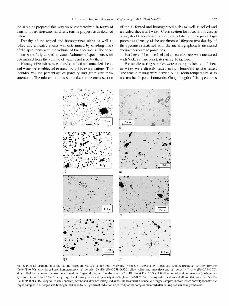
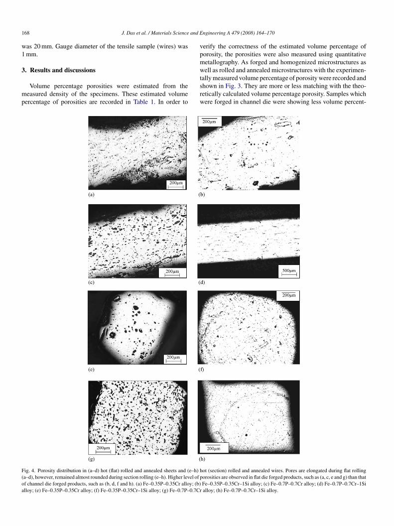
ig. 4. Porosity distribution in (a–d) hot (flat) rolled and annealed sheets and (e–h) ha–d), however, remained almost rounded during section rolling (e–h). Higher level of pf channel die forged products, such as (b, d, f and h). (a) Fe–0.35P–0.35Cr alloy; (b)lloy; (e) Fe–0.35P–0.35Cr alloy; (f) Fe–0.35P–0.35Cr–1Si alloy; (g) Fe–0.7P–0.7Cr
ngineering A 479 (2008) 164–170
erify the correctness of the estimated volume percentage oforosity, the porosities were also measured using quantitativeetallography. As forged and homogenized microstructures asell as rolled and annealed microstructures with the experimen-
ally measured volume percentage of porosity were recorded andhown in Fig. 3. They are more or less matching with the theo-etically calculated volume percentage porosity. Samples whichere forged in channel die were showing less volume percent-
ot (section) rolled and annealed wires. Pores are elongated during flat rollingorosities are observed in flat die forged products, such as (a, c, e and g) than thatFe–0.35P–0.35Cr–1Si alloy; (c) Fe–0.7P–0.7Cr alloy; (d) Fe–0.7P–0.7Cr–1Sialloy; (h) Fe–0.7P–0.7Cr–1Si alloy.
J. Das et al. / Materials Science and Engineering A 479 (2008) 164–170 169
F vealii –0.35
aTltiddarsd
swtrta
Fd
tste
aectiFnhhbeen similar porosity level of these two alloys, improvement in
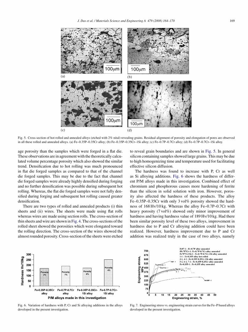
ig. 5. Cross-section of hot rolled and annealed alloys (etched with 2% nital) ren all these rolled and annealed alloys. (a) Fe–0.35P–0.35Cr alloy; (b) Fe–0.35P
ge porosity than the samples which were forged in a flat die.hese observations are in agreement with the theoretically calcu-
ated volume percentage porosity which also showed the similarrend. Densification due to hot rolling was much pronouncedn flat die forged samples as compared to that of the channelie forged samples. This may be due to the fact that channelie forged samples were already highly densified during forgingnd no further densification was possible during subsequent hotolling. Whereas, the flat die forged samples were not fully den-ified during forging and subsequent hot rolling caused greaterensification.
There are two types of rolled and annealed products (i) thinheets and (ii) wires. The sheets were made using flat rollshereas wires are made using section rolls. The cross-section of
hin sheets and wire are shown in Fig. 4. The cross-sections of the
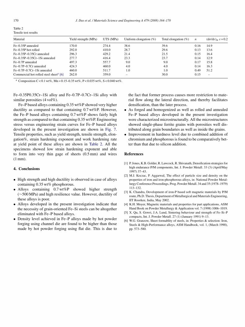
olled sheet showed the porosities which were elongated towardhe rolling direction. The cross-section of the wires showed thelmost rounded porosity. Cross-section of the sheets were etchedig. 6. Variation of hardness with P, Cr and Si alloying additions in the alloyseveloped in the present investigation.
hra
Fd
ng grains. Residual alignment of porosity and elongation of pores are observedCr–1Si alloy; (c) Fe–0.7P–0.7Cr alloy; (d) Fe–0.7P–0.7Cr–1Si alloy.
o reveal grain boundaries and are shown in Fig. 5. In generalilicon containing samples showed large grains. This may be dueo high homogenizing time and temperature used for facilitatingffective silicon diffusion.
The hardness was found to increase with P, Cr as wells Si alloying additions. Fig. 6 shows the hardness of differ-nt P/M alloys made in this investigation. Combined effect ofhromium and phosphorous causes more hardening of ferritehan the silicon in solid solution with iron. However, poros-ty also affected the hardness of these products. The alloye–0.35P–0.35Cr with only 3 vol% porosity showed the hard-ess of 168 Hv/10 kg. Whereas the alloy Fe–0.7P–0.7Cr witheavy porosity (7 vol%) showed only minor improvement ofardness and having hardness value of 189 Hv/10 kg. Had there
ardness due to P and Cr alloying addition could have beenealized. However, hardness improvement due to P and Crddition was realized truly in the case of two alloys, namely
ig. 7. Engineering stress vs. engineering strain curves for the Fe–P based alloyseveloped in the present investigation.
170 J. Das et al. / Materials Science and Engineering A 479 (2008) 164–170
Table 2Tensile test results
Material Yield strength (MPa) UTS (MPa) Uniform elongation (%) Total elongation (%) n (dσ/dε)at ε = 0.2
Fe–0.35P annealed 170.0 274.4 38.6 39.6 0.16 14.9Fe–0.35P hot rolled 292.0 410.0 28.7 29.6 0.13 13.6Fe–0.35P–0.35Cr annealed 296.3 429.2 21.4 21.5 0.15 16.4Fe–0.35P–0.35Cr–1Si annealed 277.7 416.4 23.3 23.7 0.14 12.9Fe–0.7P annealed 497.3 557.7 9.0 9.0 0.17 15.8Fe–0.7P–0.7Cr annealed 424.3 460.0 4.0 4.0 0.14 16.3Fe–0.7P–0.7Cr–1Si annealed 460.0 511.7 1.0 1.0 0.49 51.2C a
t%.
Fs
dtssdTgast(
4
•
•
•
•
•
•
R
[
[
[
[
ommercial hot rolled steel sheet [6] 262.0 359.0
a Composition C < 0.1 wt%, Mn = 0.15–0.35 wt%, P < 0.035 wt%, S < 0.040 w
e–0.35P0.35Cr–1Si alloy and Fe–0.7P–0.7Cr–1Si alloy withimilar porosities (4 vol%).
Fe–P based alloys containing 0.35 wt%P showed very higheructility as compared to that containing 0.7 wt%P. However,he Fe–P based alloys containing 0.7 wt%P shows fairly hightrength as compared to that containing 0.35 wt%P. Engineeringtress versus engineering strain curves for Fe–P based alloyseveloped in the present investigation are shown in Fig. 7.ensile properties, such as yield strength, tensile strength, elon-ation%, strain hardening exponent and work hardening ratet yield point of these alloys are shown in Table 2. All thepecimens showed low strain hardening exponent and ableo form into very thin gage of sheets (0.5 mm) and wires1 mm).
. Conclusions
High strength and high ductility is observed in case of alloyscontaining 0.35 wt% phosphorous.Alloys containing 0.7 wt%P showed higher strength(∼500 MPa) and high resilience value. However, ductility ofthese alloys is poor.Alloys developed in the present investigation indicate thatthe necessity of grain-oriented Fe–Si steels can be altogether
eliminated with Fe–P based alloys.Density level achieved in Fe–P alloys made by hot powderforging using channel die are found to be higher than thosemade by hot powder forging using flat die. This is due to[
[
– 30.0 0.15 –
the fact that former process causes more restriction to mate-rial flow along the lateral direction, and thereby facilitatesdensification, than the later process.As forged and homogenized as well as rolled and annealedFe–P based alloys developed in the present investigationwere characterized microstructurally. All the microstructuresshowed single-phase ferrite grains with porosities well dis-tributed along grain boundaries as well as inside the grains.Improvement in hardness level due to combined addition ofchromium and phosphorous is found to be comparatively bet-ter than that due to silicon addition.
eferences
1] P. Jones, K.B. Golder, R. Lawcock, R. Shivanath, Densification strategies forhigh endurance P/M components, Int. J. Powder Metall. 33 (3) (April/May1997) 37–43.
2] M.J. Koczac, P. Aggarwal, The effect of particle size and density on theproperties of iron and iron-phosphorous alloys, in: National Powder Metal-lurgy Conference Proceedings, Prog. Powder Metall. 34 and 35 (1978–1979)113–132.
3] K. Chandra, Development of iron-P based soft magnetic materials by P/Mroute, Ph.D. Thesis, Department of Metallurgical and Materials Engineering,IIT Roorkee, India, May 2002.
4] K.H. Moyer, Magnetic materials and properties for part applications, ASMHand Book on Powder Metallurgy & Application vol. 7 (1998) 1006–1019.
5] X. Qu, S. Gowri, J.A. Lund, Sintering behaviour and strength of Fe–Si–Pcompacts, Int. J. Powder Metall. 27 (1) (January 1991) 9–13.
6] W.G. Granzow, Sheet formablity of steels, in: Properties & selection: Iron,Steels & High-Performance alloys, ASM Handbook, vol. 1, (March 1990),pp. 573–580.