hardietex system covers:harditex system · pdf filecurrent design trends in residential...
TRANSCRIPT
HardieTexTM system
Technical specification
External cladding
AUSTRALIA JANUARY 2012

1 INTRODUCTION
1.1 APPLICATIONSCurrent design trends in residential construction favour the use of colour andtexture for external walls. The HardieTexTM system has been developed todeliver this colour and texture, along with design flexibility and a robustfinish, that will withstand many years of exposure to the elements.
The design flexibility of the HardieTex system is further enhanced by theuse of architectural profiles that provide a wide range of options forarchitectural detailing.
The freedom of lightweight, versatile HardieTex system makes it easy toturn the most inspiring design into reality, without heavy and often costlyengineering detail.
The HardieTex system is adaptable, and offers new design andconstruction possibilities, even with a limited budget. With the HardieTexsystem, you can have design freedom, without compromising quality andcost-effectiveness.
Start with the strong, stable, lightweight and durable HardieTex system.Then sculpt the basic form of your design, whether it is strikingly modern,or monumentally grand.
The lightweight properties of the HardieTex system makes it the idealmaterial for additions. Perfect for second-storey additions, the HardieTex system allows you to build with a reduced load, compared tobuilding with masonry. This saves time and money.
HardieTex base sheets are designed to be coated with beautiful coloursand textures, so it is easy to select a finish that will seamlessly matchnew areas to an existing building, or complement any materials used inthe original structure.
HardieTex base sheets are easily fixed to timber and steel wall framesusing common fasteners.
The specifier or the party responsible for the project must ensure thedetails in this specification are appropriate for the intended applicationand that additional detailing is performed for specific design or any areasthat fall outside the scope and specifications of this manual.
Make sure your information is up to dateWhen specifying or installing James Hardie products, ensure you have thecurrent manual. If you’re not sure you do, or if you need more information,visit www.jameshardie.com.au or Ask James Hardie™ on 13 11 03.
CONTENTS1 INTRODUCTION 21.1 Applications 21.2 Outline of system 31.3 Factors to be considered 3
2 FRAMING AND FIXING 42.1 Framing 42.2 Fixing 52.3 Fasteners 5
3 SHEET INSTALLATION 63.1 General installation 63.2 Orientation 63.3 Set jointing 73.4 Movement joints 73.5 Corners 73.6 Sheet layout around openings 73.7 Curved walls 73.8 Moisture management 7
4 MOVEMENT JOINTS 84.1 General 84.2 Control joints 84.3 Structural joints 84.4 Construction joints 8
5 DECORATIVE TREATMENT 85.1 Coating 85.2 Decorative trims 8
6 SAFE WORKING PRACTICES 9Warning 9Recommended safe working practices 9Working instructions 9Hole-forming 10Storage and handling 10Quality 10
7 PRODUCT INFORMATION 107.1 General 107.2 Product mass 107.3 Durability 107.4 Alpine regions 10
8 COMPONENTS 11
9 DETAILS 129.1 General 129.2 Slab on ground and platform floors 129.3 Windows 129.4 Eaves lining 12
10 WARRANTY 24
WE VALUE YOUR FEEDBACKTo continuously improve the development of our products andsystems, we value your input. Please send any suggestions,including your name, contact details, and relevant sketches to:
Ask James Hardie™
Fax 02 9638 [email protected]
HARDIETEX SYSTEM TECHNICAL SPECIFICATION JANUARY 2012 3
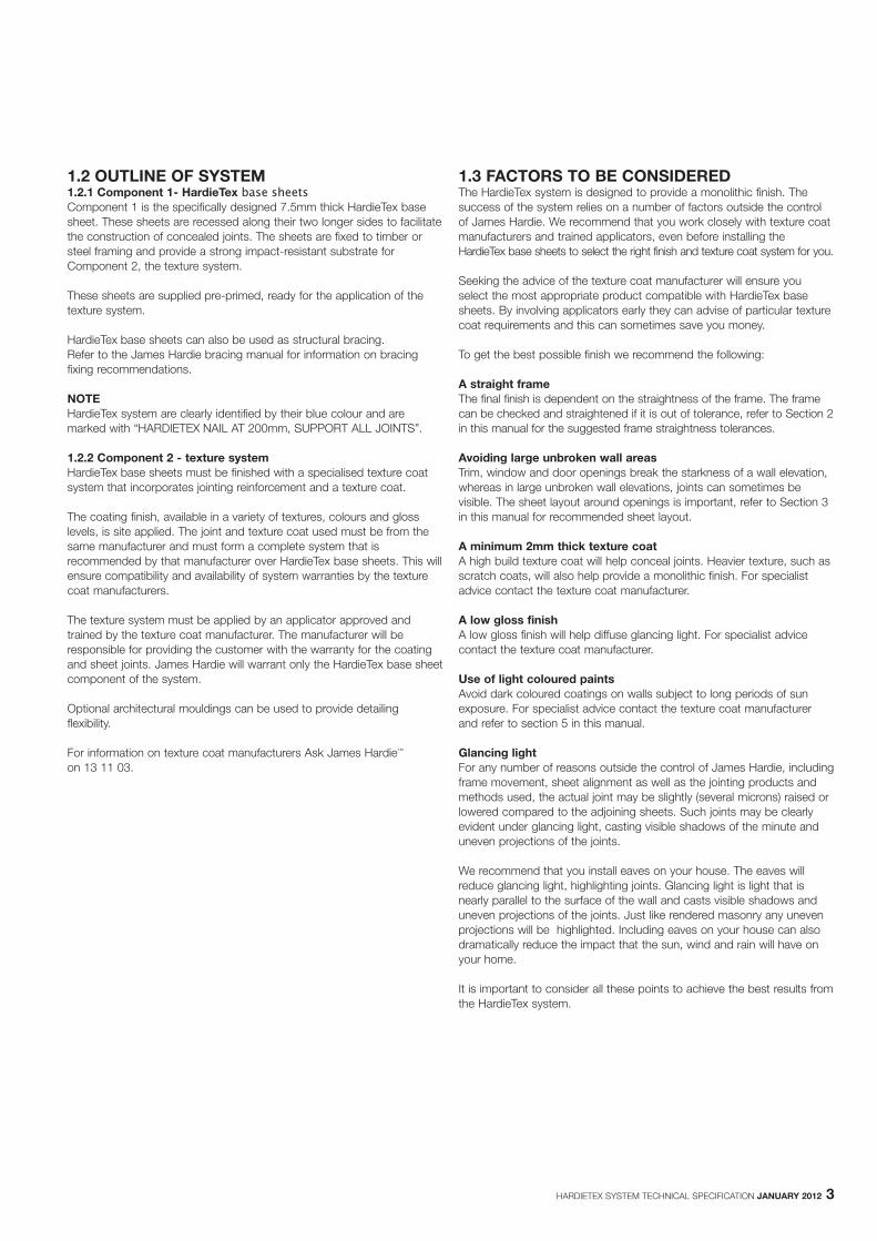
1.2 OUTLINE OF SYSTEM1.2.1 Component 1- HardieTex base sheetsComponent 1 is the specifically designed 7.5mm thick HardieTex basesheet. These sheets are recessed along their two longer sides to facilitatethe construction of concealed joints. The sheets are fixed to timber orsteel framing and provide a strong impact-resistant substrate forComponent 2, the texture system.
These sheets are supplied pre-primed, ready for the application of thetexture system.
HardieTex base sheets can also be used as structural bracing. Refer to the James Hardie bracing manual for information on bracingfixing recommendations.
NOTE HardieTex system are clearly identified by their blue colour and aremarked with “HARDIETEX NAIL AT 200mm, SUPPORT ALL JOINTS”.
1.2.2 Component 2 - texture systemHardieTex base sheets must be finished with a specialised texture coatsystem that incorporates jointing reinforcement and a texture coat.
The coating finish, available in a variety of textures, colours and glosslevels, is site applied. The joint and texture coat used must be from thesame manufacturer and must form a complete system that isrecommended by that manufacturer over HardieTex base sheets. This willensure compatibility and availability of system warranties by the texturecoat manufacturers.
The texture system must be applied by an applicator approved andtrained by the texture coat manufacturer. The manufacturer will beresponsible for providing the customer with the warranty for the coatingand sheet joints. James Hardie will warrant only the HardieTex base sheetcomponent of the system.
Optional architectural mouldings can be used to provide detailingflexibility.
For information on texture coat manufacturers Ask James Hardie™
on 13 11 03.
1.3 FACTORS TO BE CONSIDEREDThe HardieTex system is designed to provide a monolithic finish. Thesuccess of the system relies on a number of factors outside the controlof James Hardie. We recommend that you work closely with texture coatmanufacturers and trained applicators, even before installing theHardieTex base sheets to select the right finish and texture coat system for you.
Seeking the advice of the texture coat manufacturer will ensure youselect the most appropriate product compatible with HardieTex basesheets. By involving applicators early they can advise of particular texturecoat requirements and this can sometimes save you money.
To get the best possible finish we recommend the following:
A straight frameThe final finish is dependent on the straightness of the frame. The framecan be checked and straightened if it is out of tolerance, refer to Section 2in this manual for the suggested frame straightness tolerances.
Avoiding large unbroken wall areasTrim, window and door openings break the starkness of a wall elevation,whereas in large unbroken wall elevations, joints can sometimes bevisible. The sheet layout around openings is important, refer to Section 3in this manual for recommended sheet layout.
A minimum 2mm thick texture coatA high build texture coat will help conceal joints. Heavier texture, such asscratch coats, will also help provide a monolithic finish. For specialistadvice contact the texture coat manufacturer.
A low gloss finishA low gloss finish will help diffuse glancing light. For specialist advicecontact the texture coat manufacturer.
Use of light coloured paintsAvoid dark coloured coatings on walls subject to long periods of sunexposure. For specialist advice contact the texture coat manufacturerand refer to section 5 in this manual.
Glancing lightFor any number of reasons outside the control of James Hardie, includingframe movement, sheet alignment as well as the jointing products andmethods used, the actual joint may be slightly (several microns) raised orlowered compared to the adjoining sheets. Such joints may be clearlyevident under glancing light, casting visible shadows of the minute anduneven projections of the joints.
We recommend that you install eaves on your house. The eaves willreduce glancing light, highlighting joints. Glancing light is light that isnearly parallel to the surface of the wall and casts visible shadows anduneven projections of the joints. Just like rendered masonry any unevenprojections will be highlighted. Including eaves on your house can alsodramatically reduce the impact that the sun, wind and rain will have onyour home.
It is important to consider all these points to achieve the best results fromthe HardieTex system.
4 HARDIETEX SYSTEM TECHNICAL SPECIFICATION JANUARY 2012
2 FRAMING AND FIXING
2.1 FRAMING2.1.1 GeneralHardieTex base sheets can be fixed to either timber or light gauge steeldomestic framing. The framing must comply with relevant buildingregulations and standards and the requirements of this manual.
All HardieTex base sheet edges must be supported. Adequate framingmust be provided to ensure all sheet edges can be supported.
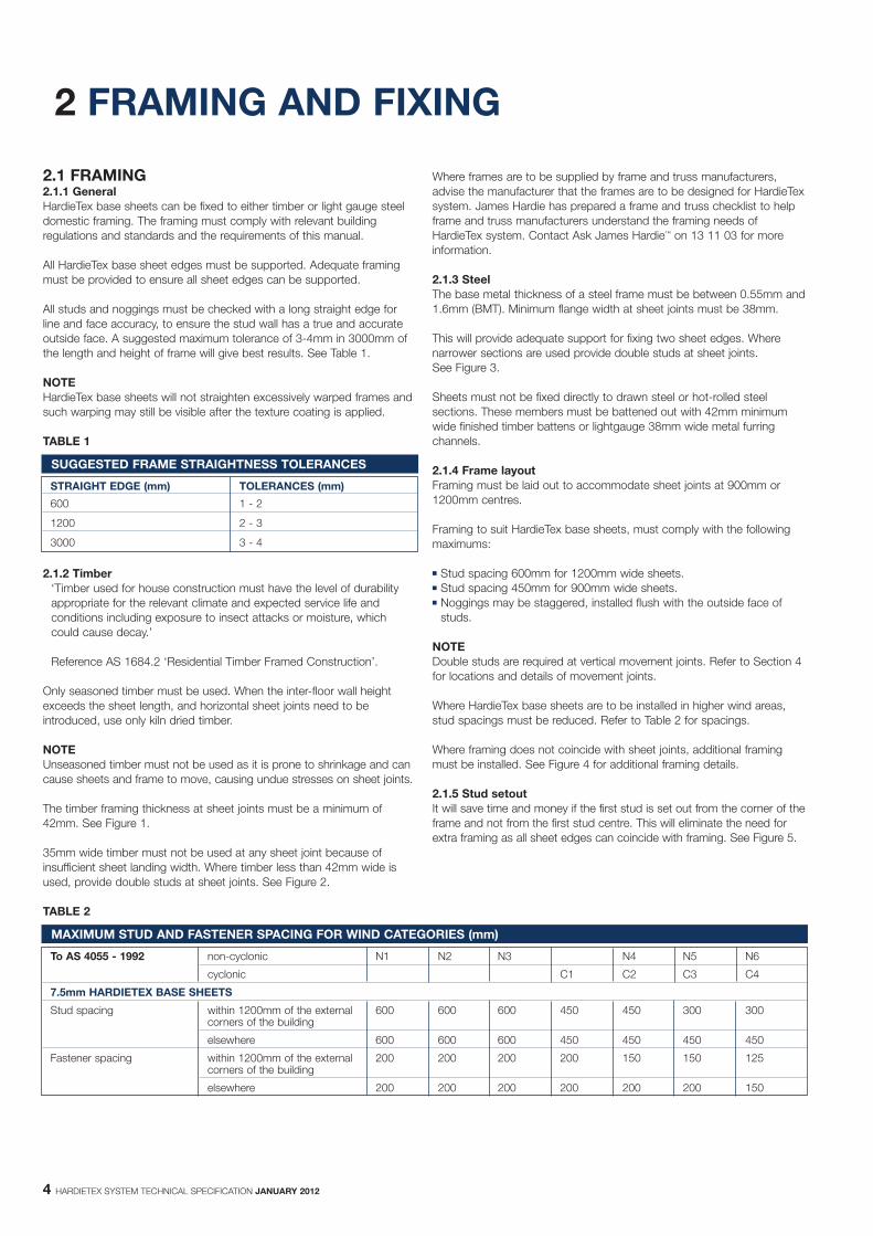
All studs and noggings must be checked with a long straight edge forline and face accuracy, to ensure the stud wall has a true and accurateoutside face. A suggested maximum tolerance of 3-4mm in 3000mm ofthe length and height of frame will give best results. See Table 1.
NOTE HardieTex base sheets will not straighten excessively warped frames andsuch warping may still be visible after the texture coating is applied.
TABLE 1
2.1.2 Timber‘Timber used for house construction must have the level of durabilityappropriate for the relevant climate and expected service life andconditions including exposure to insect attacks or moisture, whichcould cause decay.’
Reference AS 1684.2 ‘Residential Timber Framed Construction’.
Only seasoned timber must be used. When the inter-floor wall heightexceeds the sheet length, and horizontal sheet joints need to beintroduced, use only kiln dried timber.
NOTEUnseasoned timber must not be used as it is prone to shrinkage and cancause sheets and frame to move, causing undue stresses on sheet joints.
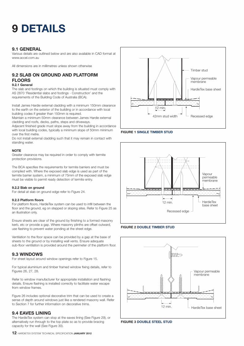
The timber framing thickness at sheet joints must be a minimum of42mm. See Figure 1.
35mm wide timber must not be used at any sheet joint because ofinsufficient sheet landing width. Where timber less than 42mm wide isused, provide double studs at sheet joints. See Figure 2.
TABLE 2
SUGGESTED FRAME STRAIGHTNESS TOLERANCES
STRAIGHT EDGE (mm) TOLERANCES (mm)
600 1 - 2
1200 2 - 3
3000 3 - 4
Where frames are to be supplied by frame and truss manufacturers,advise the manufacturer that the frames are to be designed for HardieTexsystem. James Hardie has prepared a frame and truss checklist to helpframe and truss manufacturers understand the framing needs ofHardieTex system. Contact Ask James Hardie™ on 13 11 03 for moreinformation.
2.1.3 SteelThe base metal thickness of a steel frame must be between 0.55mm and1.6mm (BMT). Minimum flange width at sheet joints must be 38mm.
This will provide adequate support for fixing two sheet edges. Wherenarrower sections are used provide double studs at sheet joints. See Figure 3.
Sheets must not be fixed directly to drawn steel or hot-rolled steelsections. These members must be battened out with 42mm minimumwide finished timber battens or lightgauge 38mm wide metal furringchannels.
2.1.4 Frame layoutFraming must be laid out to accommodate sheet joints at 900mm or1200mm centres.
Framing to suit HardieTex base sheets, must comply with the followingmaximums:
� Stud spacing 600mm for 1200mm wide sheets.� Stud spacing 450mm for 900mm wide sheets.� Noggings may be staggered, installed flush with the outside face of
studs.
NOTEDouble studs are required at vertical movement joints. Refer to Section 4for locations and details of movement joints.
Where HardieTex base sheets are to be installed in higher wind areas,stud spacings must be reduced. Refer to Table 2 for spacings.
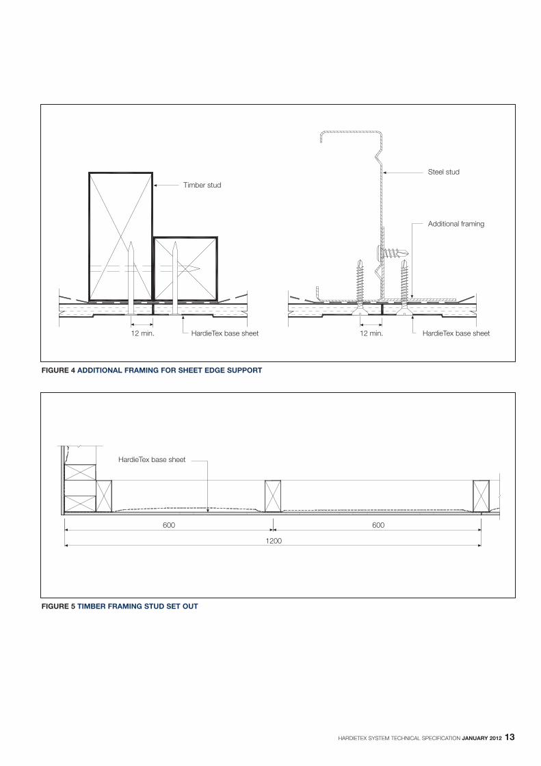
Where framing does not coincide with sheet joints, additional framingmust be installed. See Figure 4 for additional framing details.
2.1.5 Stud setoutIt will save time and money if the first stud is set out from the corner of theframe and not from the first stud centre. This will eliminate the need forextra framing as all sheet edges can coincide with framing. See Figure 5.
MAXIMUM STUD AND FASTENER SPACING FOR WIND CATEGORIES (mm)
To AS 4055 - 1992 non-cyclonic N1 N2 N3 N4 N5 N6
cyclonic C1 C2 C3 C4
7.5mm HARDIETEX BASE SHEETS
Stud spacing within 1200mm of the external 600 600 600 450 450 300 300corners of the building
elsewhere 600 600 600 450 450 450 450
Fastener spacing within 1200mm of the external 200 200 200 200 150 150 125corners of the building
elsewhere 200 200 200 200 200 200 150
HARDIETEX SYSTEM TECHNICAL SPECIFICATION JANUARY 2012 5
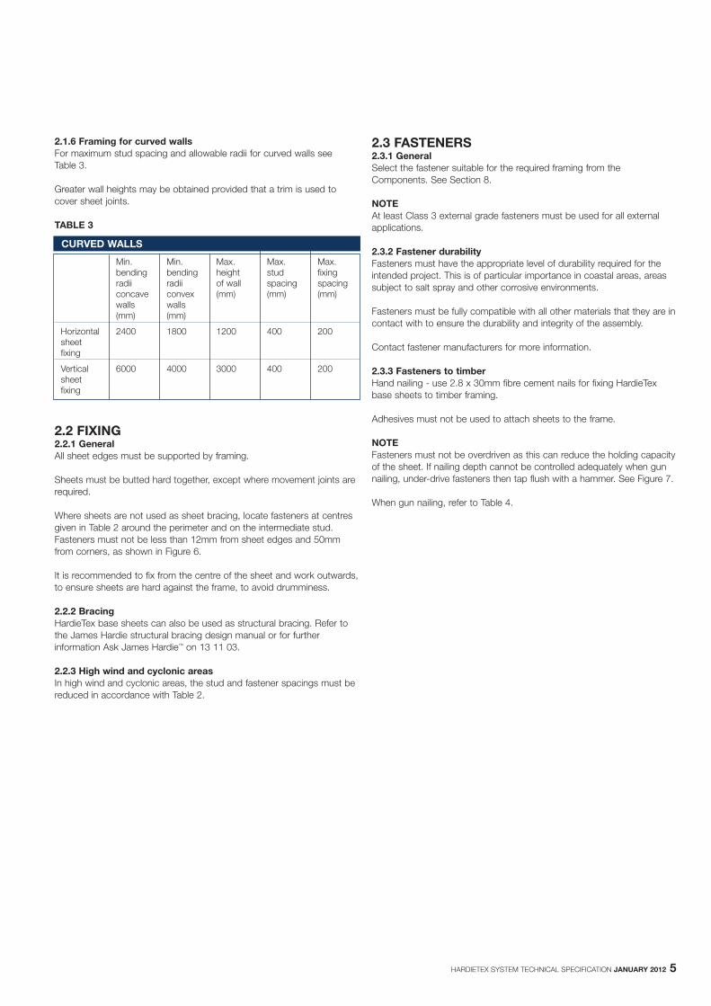
2.1.6 Framing for curved wallsFor maximum stud spacing and allowable radii for curved walls see Table 3.
Greater wall heights may be obtained provided that a trim is used tocover sheet joints.
TABLE 3
2.2 FIXING2.2.1 GeneralAll sheet edges must be supported by framing.
Sheets must be butted hard together, except where movement joints arerequired.
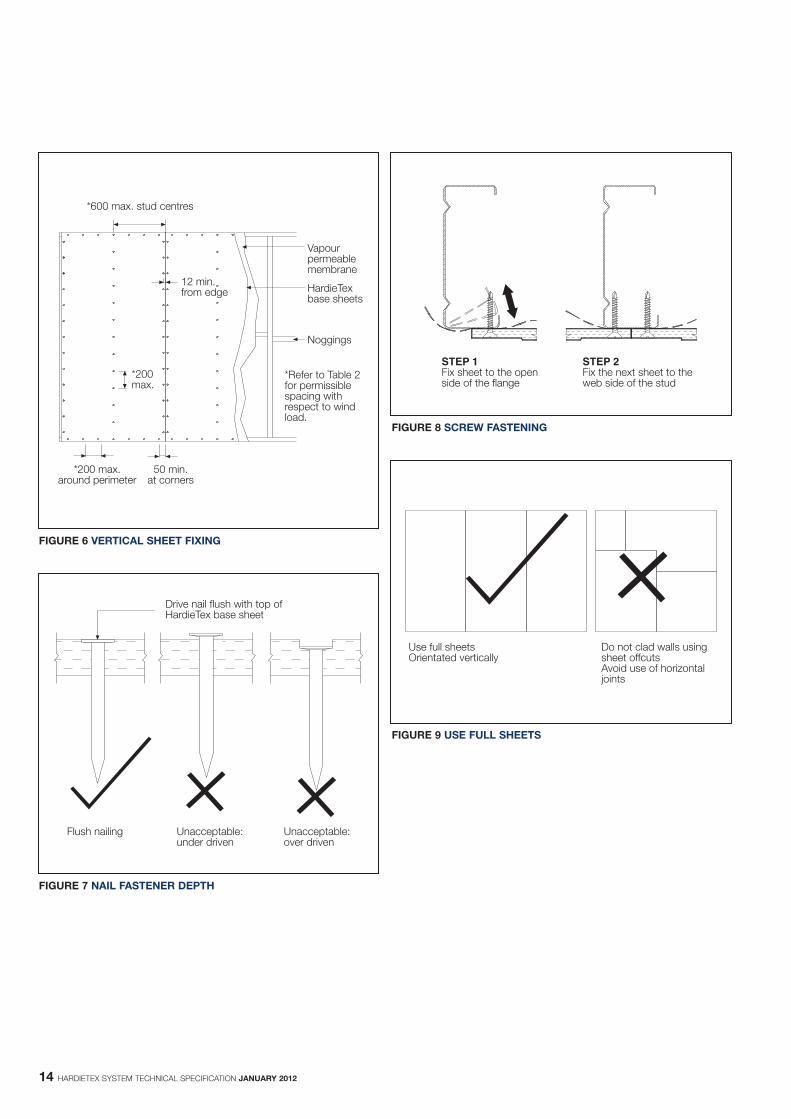
Where sheets are not used as sheet bracing, locate fasteners at centresgiven in Table 2 around the perimeter and on the intermediate stud.Fasteners must not be less than 12mm from sheet edges and 50mmfrom corners, as shown in Figure 6.
It is recommended to fix from the centre of the sheet and work outwards,to ensure sheets are hard against the frame, to avoid drumminess.
2.2.2 BracingHardieTex base sheets can also be used as structural bracing. Refer tothe James Hardie structural bracing design manual or for furtherinformation Ask James Hardie™ on 13 11 03.
2.2.3 High wind and cyclonic areasIn high wind and cyclonic areas, the stud and fastener spacings must bereduced in accordance with Table 2.
CURVED WALLS
Min. Min. Max. Max. Max.bending bending height stud fixingradii radii of wall spacing spacingconcave convex (mm) (mm) (mm)walls walls(mm) (mm)
Horizontal 2400 1800 1200 400 200sheetfixing
Vertical 6000 4000 3000 400 200sheetfixing
2.3 FASTENERS2.3.1 GeneralSelect the fastener suitable for the required framing from theComponents. See Section 8.
NOTEAt least Class 3 external grade fasteners must be used for all externalapplications.
2.3.2 Fastener durabilityFasteners must have the appropriate level of durability required for theintended project. This is of particular importance in coastal areas, areassubject to salt spray and other corrosive environments.
Fasteners must be fully compatible with all other materials that they are incontact with to ensure the durability and integrity of the assembly.
Contact fastener manufacturers for more information.
2.3.3 Fasteners to timberHand nailing - use 2.8 x 30mm fibre cement nails for fixing HardieTexbase sheets to timber framing.
Adhesives must not be used to attach sheets to the frame.
NOTE Fasteners must not be overdriven as this can reduce the holding capacityof the sheet. If nailing depth cannot be controlled adequately when gunnailing, under-drive fasteners then tap flush with a hammer. See Figure 7.
When gun nailing, refer to Table 4.

2.3.4 Fastening to steelFor steel framing of thickness 0.55mm to 0.75mm BMT, 30mm BuildexFibreTEKS self drilling screws.
For steel framing of thickness 0.80mm to 1.6mm. Use 8g-32mmHardiDrive® screws.
Fasteners should be screwed as close as possible to the stud corners toavoid deflection of the stud flange. See Figure 8.
2.3.5 Screw gun specificationUse variable speed screw guns with high torque, a maximum speed of2500rpm, fitted with a depth control attachment.
Set the depth control attachment to avoid overdriving. As the screwthread begins to pull into the steel frame, drop the revs back to bed thehead flush with the surface of the sheet.
The bottom edge of HardieTex base sheets must not come into frequentcontact with moisture. Ensure bottom edge of sheets are not buried or inan application where they will be exposed to ponding water.
3.2 ORIENTATION3.2.1 VerticalVertical sheet installation layout is recommended for the following reasons:
� The longer sides of the sheets are recessed, facilitating vertical sheetjoints, horizontally laid sheet sheets could require significant sitegrinding.
� Noggings can be staggered rather than in line.� Vertical sheet installation minimises wastage as sheet lengths and
widths suit wall heights and stud spacing.� After coating, vertical joints are generally less obvious in glancing light
conditions than horizontal joints.
TABLE 4
NOTES1. Fasteners with equivalent dimensions, (ie head size and shape, shank
diameter and length to those above) are acceptable for use.2. All fasteners are to be galvanised or suitably coated for intended
external application.3. Nailing guns must be fitted with flush drive attachments.4. Some nailing guns incorporate an adjustable head set to control nail
depth (eg Duo-Fast coil nailer and Senco coil nailer.)5. When gun nailing, apply pressure to the face of the cladding by
holding the cladding against the stud to reduce blow out at back ofthe sheet.
Nail gun manufacturers have supplied the information contained in thistable. Should a nail gun model or nail shown in the table not be available,please contact the relevant nail gun manufacturer for advice.If the nail gun overdrives sheets, contact nail gun manufacturer for advice.
3.1 GENERAL INSTALLATIONPlanning sheet layout is an essential part of installation to minimise thenumber of sheet joints and material wastage. The two main areas to beconsidered are sheet orientation and jointing.
In all cases use full sheets and do not use offcuts to clad walls. See Figure 9.
Sheets must be fixed vertically, commencing from a corner. Where steelframing is used, ensure studs are placed so sheets can be progressivelyfixed in the sequence indicated in Figure 6.
Where wall heights between floors are greater than a standard sheet,place small sheets at the top of the full sheet. See Figure 10.
Ensure that HardieTex base sheets are not finished hard against render,tiling, timber decks or concrete slab. Provision must be made for frameand sheet movement.
6 HARDIETEX SYSTEM TECHNICAL SPECIFICATION JANUARY 2012
GUN NAILING NOTES
COIL NAILER NAILS
Manufacturer Name Manufacturer Name Size
Hitachi VH650 coil nailer Otter Galv. coil nail 38mm x 2.5mm dia.45mm x 2.2mm dia.50mm x 2.2mm dia.
Paslode Impulse compact nailer Paslode Impulse DekFast® 50mm 50mm x 2.87mm dia.(B20544) Value Pack (B20561V)
Impulse DekFast® 50mm 50mm x 2.87mm dia.Handy Pack (B20557)
Duo-Fast KD665A coil nailer Duo-Fast C27/32 GD coil nail (D41800) 32mm x 2.7mm dia.(Part No. D40040)
Stanley-Bostitch N80C coil nailer Stanley-Bostitch AC45P250 gal coil nail 45mm x 2.5mm dia.
Senco SCN-60 coil nailer (fitted with Senco BTN 45 ADB Weatherex gal 45mm x 2.5mm dia.adjustable depth of drive) and Sencoted
3 SHEET INSTALLATION
HARDIETEX SYSTEM TECHNICAL SPECIFICATION JANUARY 2012 7
3.2.2 HorizontalHorizontal sheet layout is only recommended where the maximum depthof cladding is 1200mm (one sheet width), horizontal sheet installation ismore suitable for applications such as fascias.
When fixing sheets horizontally. Refer to Table 2 for fastener spacings.Ensure sheets are fastened to all studs.
3.3 SET JOINTINGThe set (recessed-edge) joint is formed between adjoining vertical edgesof HardieTex system refer to Figure 11.
The sheets are butted hard together with no gaps being left betweensheets.
Set joints are also required at sheet ends where inter-floor heights aregreater than the length of a standard sheet. See Figure 10.
HardieTex system comes with two recessed edges to facilitate easysetting of the joints. If an additional recess is required, the recess can besite ground. See Figure 12.
Where edges have been site recessed, ensure correct primer has beenused to pre-prime sheet recess before application of texture coat. Check with texture coat manufacturer for details on primers that arerecommended for the texture coat system selected.
Use a portable angle grinder fitted with a strong thick diamond orcarborundum blade or similar and a dust extraction unit. A suitable tool isan angle grinder fitted with the Hitachi Easy Bevel attachment and dustextraction apparatus.
3.4 MOVEMENT JOINTSMovement joints are joints that control the structural movement betweenthe sheets and frame. Generally these joints are required at wall runs over5.4m and at floor levels. Refer to Section 4 for an explanation and detailsof movement joints.
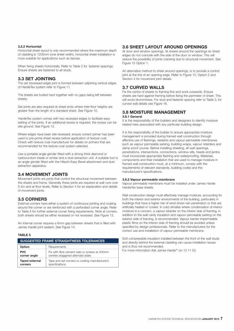
3.5 CORNERSExternal corners have either a system of continuous jointing and coatingaround the corner or are reinforced with a perforated corner angle. Referto Table 5 for further external corner fixing requirements. Note at corners,both sheets should be either recessed or not recessed. See Figure 13.
An internal corner requires a 6mm gap between sheets that is filled withJames Hardie joint sealant. See Figure 14.
TABLE 5
3.6 SHEET LAYOUT AROUND OPENINGSAt door and window openings, fix sheets around the openings so sheetedges do not coincide with the side of the door or window. This willreduce the possibility of joints cracking due to structural movement. SeeFigure 15 Option 1.
An alternative method to sheet around openings, is to provide a controljoint at the line of an opening edge. Refer to Figure 15, Option 2 andSection 4 for movement joint details.
3.7 CURVED WALLSFix the centre of sheets to framing first and work outwards. Ensuresheets are hard against framing before fixing the perimeter of sheet. Thiswill avoid drumminess. For stud and fastener spacing refer to Table 3, forcurved wall details see Figure 16.
3.8 MOISTURE MANAGEMENT3.8.1 GeneralIt is the responsibility of the builders and designers to identify moisturerelated risks associated with any particular building design.
It is the responsibility of the builder to ensure appropriate moisturemanagement is provided during framed wall construction througheffective use of flashings, sealants and vapour permeable membranessuch as vapour permeable sarking, building wraps, vapour retarders anddamp proof course. Before installing sheeting, all wall openings,penetrations, intersections, connections, window sills, heads and jambsmust incorporate appropriate flashing and waterproofing. Materials,components and their installation that are used to manage moisture inframed wall construction must, at a minimum, comply with therequirements of relevant standards, building codes and themanufacturer’s specifications.
3.8.2 Vapour permeable membraneVapour permeable membrane must be installed under James HardieHardieTex base sheets.
Wall construction design must effectively manage moisture, accounting forboth the interior and exterior environments of the building, particularly inbuildings that have a higher risk of wind driven rain penetration or that areartificially heated or cooled. In cold climates where condensation of interiormoisture is a concern, a vapour retarder on the interior side of framing, inaddition to the wall cavity insulation and vapour permeable sarking on theexterior side of framing, is recommended. Vapour barrier impermeableplastic films on the interior side of framing should be avoided unlessspecified by design professionals. Refer to the manufacturers for thecorrect use and installation of vapour permeable membrane.
Soft compressible insulation installed between the front of the wall studsand directly behind the external cladding can cause installation issuesand is thus not recommended. For more information Ask James HardieTM on 13 11 03.
SUGGESTED FRAME STRAIGHTNESS TOLERANCES
Option Requirements
PVC Fix with fibre cement nails or screws at 200mmcorner angle centres staggered alternate sides
Taped external Tape and set corners to coating manufacturer’scorners specifications
8 HARDIETEX SYSTEM TECHNICAL SPECIFICATION JANUARY 2012
4 MOVEMENT JOINTS
4.1 GENERALMovement joints are designed to take up the structural movementbetween the sheets and building frame.
4.2 CONTROL JOINTS4.2.1 Vertical control jointsVertical control joints must be located in wall runs over 5.4m. For anexample of vertical joint layout refer to Figure 17.
In this example the wall run is over 13.2m and requires at least 2 controljoints located at a maximum wall run of 5.4m.
The control joints have been positioned to suit window and dooropenings. There are a number of alternative solutions to the location ofvertical control joints. Location of control joints should be consideredbefore installation of sheeting begins.
NOTE Avoid placing control joints at doors or windows when using architraves.
These control joints require a 6mm gap between sheets. Refer to Figure 18 for details of vertical movement joints.
NOTE Control joints must be formed using sheets with square cut edges andrequire a 6mm gap between sheets.
The vertical control joint must be supported on double studs. See Figure 18.
4.2.2 Horizontal control jointsHorizontal control joints must be located in walls at 3.6m maximumcentres. They are also required at floor joist level and at gable ends. See Figure 17.
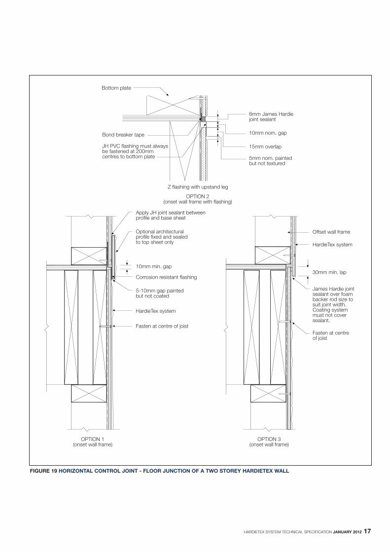
For details of horizontal control joints refer to Figure 19. When usingarchitectural trims to cover control joints, ensure that trims are free tofloat over the bottom sheet by only fixing trim to upper sheet. This willallow for sheet and frame movement.
A horizontal control joint is also required for floor joists that are madefrom laminated timber “I” beams. These beams should be sufficientlypacked out to accommodate fixing of HardieTex base sheets.
4.3 STRUCTURAL JOINTSStructural movement joints must be provided when required by thedesigner. They must have total framing separation, including top andbottom plate, lining and cladding to allow for the structural framingexpansion and contraction that can occur. See Figure 20.
4.4 CONSTRUCTION JOINTS4.4.1 VerticalVertical construction joints are required where HardieTex base sheetsconstruction intersects with an existing structure (See Figure 21 andFigure 22).
If cement render is applied to masonry wall, do not render hard upagainst HardieTex base sheet edge. Leave a 6mm joint between therender and HardieTex base sheet and fill with James Hardie joint sealantover bond breaker tape. Coating system must not cover sealant.
4.4.2 HorizontalHorizontal construction joints are required where upper level HardieTexsystem construction joins an existing ground floor structure. See Figure 23.
5 DECORATIVETREATMENT
5.1 COATINGCoating systems applied to the HardieTex base sheets must besufficiently flexible to accommodate stresses across sheet joints. Thejointing and coating systems suitable for use with HardieTex system areusually 100% acrylic or pure elastomeric high build texture coatings.
Use texture coating systems that have a minimum thickness of2mm.Refer to the coating manufacturer to determine suitable coating for usewith HardieTex base sheets.
These systems must be applied by an applicator trained and approvedby the coating manufacturer.
Refer to Section 1.3 at the beginning of this manual for furtherinformation on factors to be considered.
Where HardieTex base sheets are to be left uncoated for a considerable time,contact the texture coat manufacturer for advice on suitability of texture coat.
It is the responsibility of the applicator to use the appropriatecomponents and compounds sufficient to eliminate cracking undernormal building settlement conditions.
For more information regarding coating performance, maintenance andlevels of finish refer to Fact Sheet T12 available from and produced bythe Australian Paint Manufacturers’ Federation Inc. This document is notto be used as a substitute for the manufacturer’s requirements.
HardieTex base sheets must be texture coated within 90 days of theinstallation.
NOTE: In areas exposed to marine salt spray, it is recommended thattexture coatings be applied as soon as possible after sheet fixing toprevent salt build up that could lead to fastener corrosion. For informationon texture coats in marine environments contact the texture coatmanufacturer.
The texture coat colour applied to both the HardieTex base sheets andPVC accessories, must have a Light Reflective Valve (LRV) greater than 40%. Refer to the texture coat manufacturer for the coating’s LRV.
James Hardie does not recommend tiling in an external application.
5.2 DECORATIVE TRIMSDecorative mouldings, refer to Figure 32, can be used to enhance abuilding, or to create a distinctive style of building facade, eg Tuscan etc.In addition, they can also be strategically placed to hide movement joints.
Mouldings are available for various parts of a building, such as quoining,banding, or to trim windows or doors.
The following types of decorative mouldings are available:� Cement based profiles (these have superior long-term durability and
impact resistance).� Expanded polystyrene with protective coating (eg fibreglass,
polyurethane).
Where moulds are used to hide movement joints they must be allowed tofloat over the joint. The mould must be attached to one sheet only andmust not bridge the joint. See Figure 19.
The moulds must be installed strictly in accordance with themanufacturer’s specifications. For further information on mouldingsuppliers contact Ask James Hardie™ on 13 11 03.
NOTE: Decorative mouldings do not provide effective flashings.Openings and other critical areas must still be flashed using traditionalconstruction methods.
HARDIETEX SYSTEM TECHNICAL SPECIFICATION JANUARY 2012 9
6 SAFE WORKING PRACTICES
WORKING INSTRUCTIONSRefer to recommended safe working practices before starting any cuttingor machining of product.
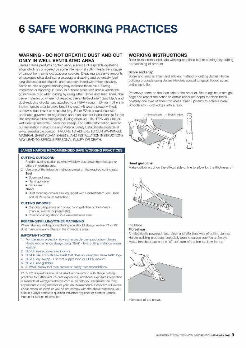
Score and snapScore and snap is a fast and efficient method of cutting James Hardiebuilding products using James Hardie’s special tungsten tipped scoreand snap knife.
Preferably score on the face side of the product. Score against a straightedge and repeat the action to obtain adequate depth for clean break –normally one third of sheet thickness. Snap upwards to achieve break.Smooth any rough edges with a rasp.
Hand guillotineMake guillotine cut on the off-cut side of line to allow for the thickness of
the blade.FibreshearAn electrically powered, fast, clean and effortless way of cutting JamesHardie building products, especially around curves such as archways.Make fibreshear cut on the ‘off-cut’ side of the line to allow for the
thickness of the shear.
WARNING - DO NOT BREATHE DUST AND CUTONLY IN WELL VENTILATED AREAJames Hardie products contain sand, a source of respirable crystallinesilica which is considered by some international authorities to be a causeof cancer from some occupational sources. Breathing excessive amountsof respirable silica dust can also cause a disabling and potentially fatallung disease called silicosis, and has been linked with other diseases.Some studies suggest smoking may increase these risks. Duringinstallation or handling: (1) work in outdoor areas with ample ventilation; (2) minimise dust when cutting by using either 'score and snap' knife, fibrecement shears or, where not feasible, use a HardieBladeTM Saw Blade anddust-reducing circular saw attached to a HEPA vacuum; (3) warn others inthe immediate area to avoid breathing dust; (4) wear a properly-fitted,approved dust mask or respirator (e.g. P1 or P2) in accordance withapplicable government regulations and manufacturer instructions to furtherlimit respirable silica exposures. During clean-up, use HEPA vacuums orwet cleanup methods - never dry sweep. For further information, refer toour installation instructions and Material Safety Data Sheets available atwww.jameshardie.com.au. FAILURE TO ADHERE TO OUR WARNINGS,MATERIAL SAFETY DATA SHEETS, AND INSTALLATION INSTRUCTIONSMAY LEAD TO SERIOUS PERSONAL INJURY OR DEATH.
JAMES HARDIE RECOMMENDED SAFE WORKING PRACTICES
CUTTING OUTDOORS1. Position cutting station so wind will blow dust away from the user or
others in working area.2. Use one of the following methods based on the required cutting rate:
Best� Score and snap� Hand guillotine� FibreshearGood� Dust reducing circular saw equipped with HardieBladeTM Saw Blade
and HEPA vacuum extraction.
CUTTING INDOORS� Cut only using score and snap, hand guillotine or fibreshears
(manual, electric or pneumatic).� Position cutting station in a well-ventilated area.
REBATING/DRILLING/OTHER MACHININGWhen rebating, drilling or machining you should always wear a P1 or P2 dust mask and warn others in the immediate area.
IMPORTANT NOTES1. For maximum protection (lowest respirable dust production), James
Hardie recommends always using “Best” - level cutting methods where feasible.
2. NEVER use a power saw indoors.3. NEVER use a circular saw blade that does not carry the HardieBlade® logo.4. NEVER dry sweep - Use wet suppression or HEPA vacuum.5. NEVER use grinders.6. ALWAYS follow tool manufacturers’ safety recommendations.
P1 or P2 respirators should be used in conjunction with above cuttingpractices to further reduce dust exposures. Additional exposure informationis available at www.jameshardie.com.au to help you determine the mostappropriate cutting method for your job requirements. If concern still existsabout exposure levels or you do not comply with the above practices, youshould always consult a qualified industrial hygienist or contact James Hardie for further information.
Scored edge Straight edge
10 HARDIETEX SYSTEM TECHNICAL SPECIFICATION JANUARY 2012
7 PRODUCT INFORMATION
7.1 GENERALHardieTex base sheet is a cellulose fibre reinforced cement buildingproduct. The basic composition is Portland cement, ground sand,cellulose fibre and water.
HardieTex base sheet is manufactured to AS/NZS 2908.2 ‘Cellulose-Cement Products Part 2: Flat Sheets’ (ISO 8336 ‘Fibre Cement Flat Sheets’).
HardieTex system is classified Type A, Category 2 in accordance withAS/NZS 2908.2 ‘Cellulose-Cement Products’.
For Material Safety Data Sheets (MSDS) visit www.jameshardie.com.au orAsk James Hardie™ on 13 11 03.
7.2 PRODUCT MASSBased on equilibrium moisture content the approximate mass of HardieTex base sheet is 10.10kg/m2.
7.3 DURABILITY7.3.1 Resistance to moisture/rottingHardieTex base sheet has demonstrated resistance to permanentmoisture induced deterioration (rotting) by passing the following tests inaccordance with AS/NZS 2908.2:
� Water permeability (Clause 8.2.2)� Warm water (Clause 8.2.4)� Heat rain (Clause 6.5)� Soak dry (Clause 8.2.5)
7.3.2 Resistance to fireThe HardieTex base sheet is suitable where non-combustible materialsare required in accordance with C1.12 of the Building Code of Australia.
James Hardie building products have been tested by CSIRO inaccordance with AS/NZS 3837 and are classified as conforming toGroup 1 material (highest and best result possible), with an averagespecific extinction area far lower than the permissible 250m2/kg, asreferenced in Specification C1.10a of the BCA.”
7.3.3 Resistance to termite attackBased on testing completed by CSIRO Division of Forest Products andEnsis Australia James Hardie building products have demonstratedresistance to termite attack.
7.4 ALPINE REGIONSIn regions subject to freeze/thaw conditions, all James Hardie fibrecement external cladding must be installed and painted in the warmermonths of the year where the temperature does not create freezeand thaw conditions or paint issues. The cladding must be paintedimmediately after installation. In addition, fibre cement cladding must notbe in direct contact with snow and/or ice build up for extended periods,e.g. external walls in alpine regions subject to snow drifts over winter.
Furthermore, a reputable paint manufacturer must be consulted inregards to a suitable product, specifications and warranty. The paintapplication must not be carried out if the air temperature or the substratetemperature is outside the paint manufacturer’s recommendationincluding the specified drying temperature range.
James Hardie external cladding products are tested for resistance tofrost in accordance with AS/NZS 2908.2 Clause 8.2.3.
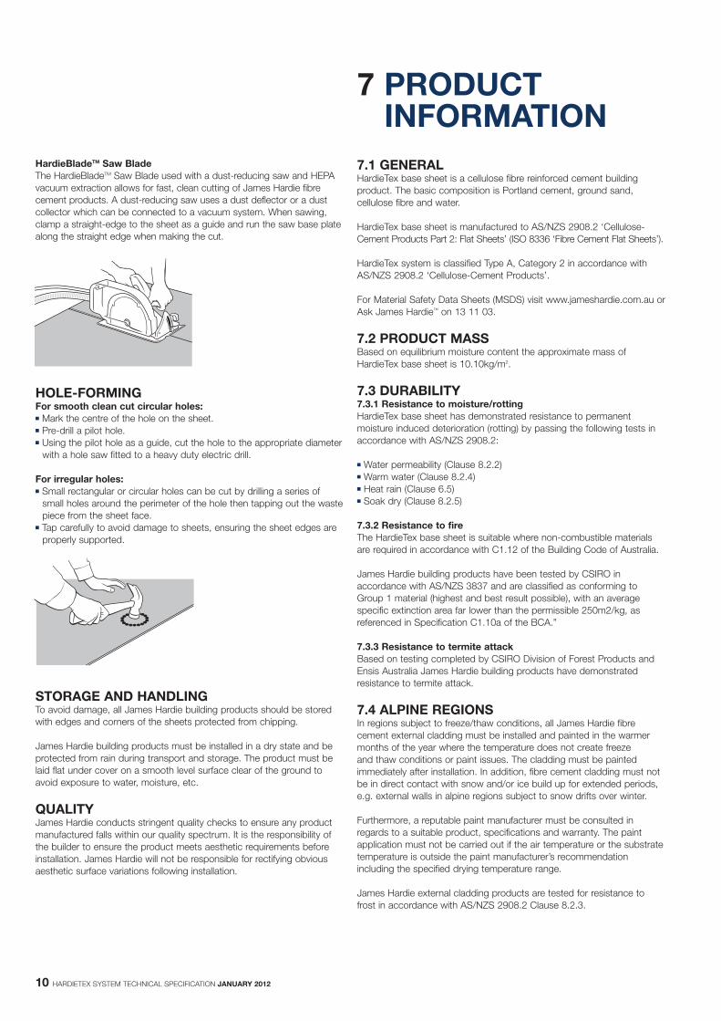
HardieBladeTM Saw BladeThe HardieBladeTM Saw Blade used with a dust-reducing saw and HEPAvacuum extraction allows for fast, clean cutting of James Hardie fibrecement products. A dust-reducing saw uses a dust deflector or a dustcollector which can be connected to a vacuum system. When sawing,clamp a straight-edge to the sheet as a guide and run the saw base platealong the straight edge when making the cut.
HOLE-FORMINGFor smooth clean cut circular holes:� Mark the centre of the hole on the sheet.� Pre-drill a pilot hole.� Using the pilot hole as a guide, cut the hole to the appropriate diameter
with a hole saw fitted to a heavy duty electric drill.
For irregular holes:� Small rectangular or circular holes can be cut by drilling a series of
small holes around the perimeter of the hole then tapping out the wastepiece from the sheet face.
� Tap carefully to avoid damage to sheets, ensuring the sheet edges areproperly supported.
STORAGE AND HANDLINGTo avoid damage, all James Hardie building products should be storedwith edges and corners of the sheets protected from chipping.
James Hardie building products must be installed in a dry state and beprotected from rain during transport and storage. The product must belaid flat under cover on a smooth level surface clear of the ground toavoid exposure to water, moisture, etc.
QUALITYJames Hardie conducts stringent quality checks to ensure any productmanufactured falls within our quality spectrum. It is the responsibility ofthe builder to ensure the product meets aesthetic requirements beforeinstallation. James Hardie will not be responsible for rectifying obviousaesthetic surface variations following installation.

HARDIETEX SYSTEM TECHNICAL SPECIFICATION JANUARY 2012 11
8 COMPONENTS
The following checklist describes the components required to install HardieTex system.
HARDIETEX BASE SHEET - SHEET PRIMED BLUE
Surface: Flat sheet-blue coloured. Edges to long sides of sheets recessed for set jointing. Short sides square edged, to be site recessed where jointing is required.All HardieTex base sheets are clearly marked with; “HARDIETEX” NAIL AT 200mm CENTRES, SUPPORT ALL JOINTS” on the front of the sheets.
Mass: 7.5mm thick: 10.10kg/m2Length (mm): Width (mm): Thickness (mm):2440 900 7.5
1200 7.52725 900 7.5
1200 7.53000 900 7.5
1200 7.5
HARDIETEX SYSTEM COMPONENTS
HardieDriveTM Screw 32mm longA class 3 finish self-tapping wing-tipped screw for fastening to 500 Per Box0.8mm to 1.6mm BMT steel frames. Part No: 305532NOTE: Contact your fastener manufacturer for fasteners with suitable For detailed information refer to Clause 2.3 Fastenerscorrosion resistance.
James HardieTM 7.5mm PVC Starter Strip. 3,000mm longA perforated PVC extrusion, used with HardieTex® sheet to provide a 25 Per Packstraight edge to finish the texture coating or used with PrimeLine® Part No: 305568Newport or Summit weatherboard to secure the bottom row at the correct angle. See Figure 24 in installation manual.
HardieTexTM 7.5mm PVC Z Flashing. 3,000mm LongA PVC extrusion for use with HardieTexTM system to provide an 25 Per Packalternative detail option at horizontal control joints. Part No: 305569
James HardieTM Joint Sealant. 300ml cartridge 20 Per BoxA general purpose, paintable, exterior grade polyurethane joint sealant. Part No: 305534
Detailed information: refer to Figures 14, 18 – 22, 26, 27, 29 and 30
James HardieTM Score and Snap Knife 20 Per BoxA tungsten tipped knife for scoring fibre cement sheets. Part No: 305576
James HardieTM Fibreshears 1 EachElectric tool for cutting fibre cement sheets. Part No: 300653
HardieBladeTM Saw Blade. 185mm diameterA 185mm diameter poly-diamond blade for fast and clean cutting of 1 EachJames Hardie fibre cement. Part No: 300660
COMPONENTS NOT SUPPLIED BY JAMES HARDIEJames Hardie recommends the use of the following products in conjunction with the HardieTex system. James Hardie does not supply these products and doesnot provide a warranty for their use. Please contact the component manufacturers for information on their warranties and further information on their products.
Fibre cement nailsGalvanised nails for timberNOTE: In coastal and other areas subject to salt spray, contact your fastener manufacturer for fasteners 2.8 x 30mmwith suitable corrosion resistance
Buildex FibreTEKS® 30mm for 0.55 - 0.75mm BMT® denotes a registered mark of Buildex
PVC perforated external cornerTaped and set corners - to satisfy coating manufacturer’s specifications.
Textured finish coating systemsProprietary jointing and coating systems applied in accordance with the coating manufacturer’s specification by their accredited applicators. Taped and set corners when required- to satisfy coating manufacturer’s specification. For detailed information on these systems refer to Sections 1- Introduction and 7- Decorative treatmentNOTE: It is essential that components from different suppliers are not combined or blended, as they may not be compatible.
Vapour permeable membraneMust have the following properties in accordance with AS/NZS 4200.1Vapour barrier - low or medium.Water barrier - high.
Hitachi Easy Bevel attachment fitted to suitable angle grinder, with dust extraction apparatus fitted.
LengthWidth
*All dimensions and masses are approximate and subject to manufacture tolerances.
12 HARDIETEX SYSTEM TECHNICAL SPECIFICATION JANUARY 2012
9 DETAILS
9.1 GENERALVarious details are outlined below and are also available in CAD format atwww.accel.com.au
All dimensions are in millimetres unless shown otherwise
9.2 SLAB ON GROUND AND PLATFORMFLOORS9.2.1 GeneralThe slab and footings on which the building is situated must comply withAS 2870 ‘Residential slabs and footings - Construction’ and therequirements of the Building Code of Australia (BCA).
Install James Hardie external cladding with a minimum 150mm clearanceto the earth on the exterior of the building or in accordance with localbuilding codes if greater than 150mm is required.Maintain a minimum 50mm clearance between James Hardie externalcladding and roofs, decks, paths, steps and driveways. Adjacent finished grade must slope away from the building in accordancewith local building codes, typically a minimum slope of 50mm minimumover the first metre. Do not install external cladding such that it may remain in contact withstanding water.
NOTEGreater clearance may be required in order to comply with termiteprotection provisions.
The BCA specifies the requirements for termite barriers and must becomplied with. Where the exposed slab edge is used as part of thetermite barrier system, a minimum of 75mm of the exposed slab edgemust be visible to permit ready detection of termite entry.
9.2.2 Slab on groundFor detail at slab on ground edge refer to Figure 24.
9.2.3 Platform floorsFor platform floors, HardieTex system can be used to infill between thefloor and the ground, eg on stepped or sloping sites. Refer to Figure 25 asan illustration only.
Ensure sheets are clear of the ground by finishing to a formed masonrykerb, etc or provide a gap. Where masonry plinths are offset outward,use flashing to prevent water ponding at the sheet edge.
Ventilation to the floor space can be provided by a gap at the base ofsheets to the ground or by installing wall vents. Ensure adequate sub-floor ventilation is provided around the perimeter of the platform floor.
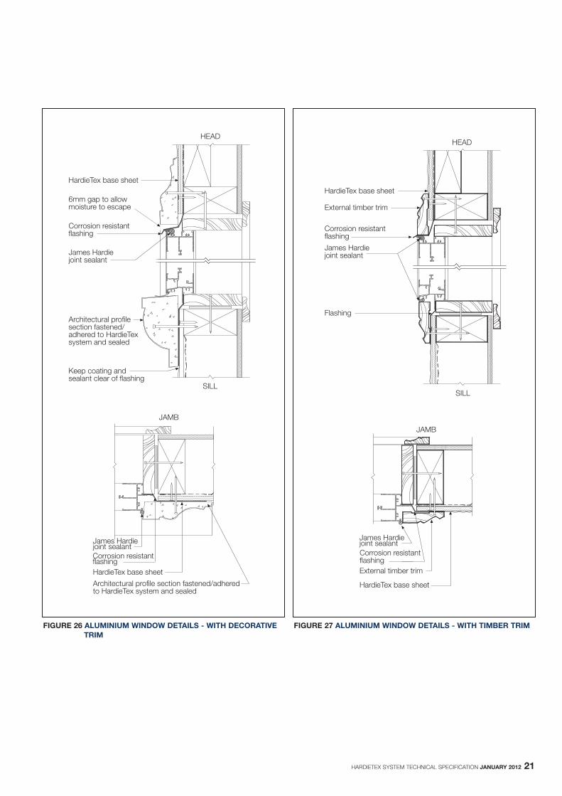
9.3 WINDOWSFor sheet layout around window openings refer to Figure 15.
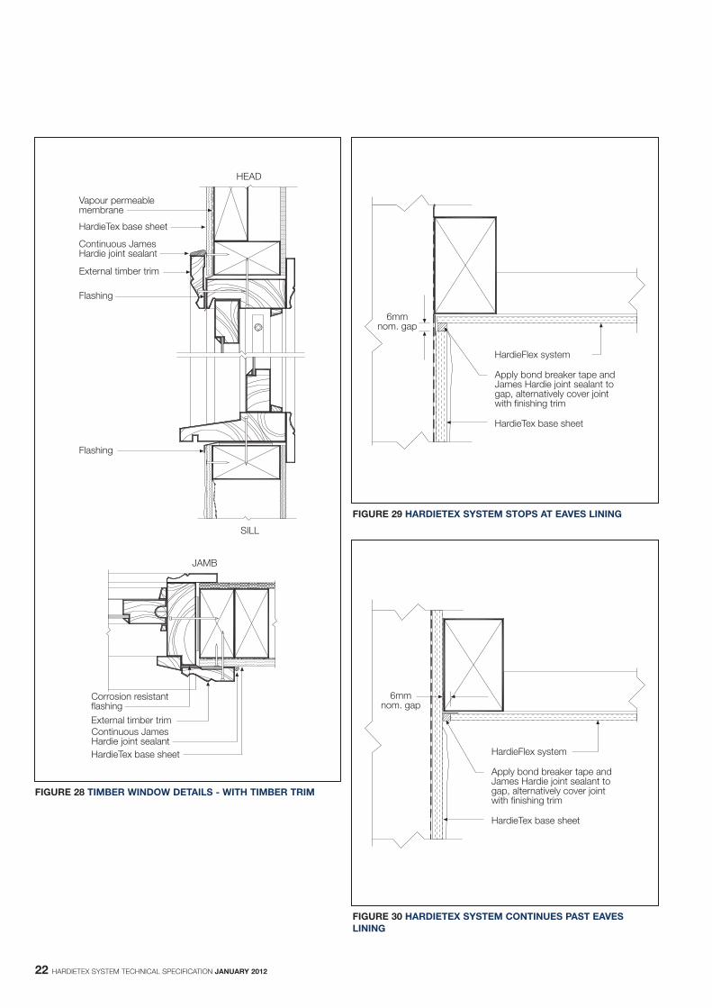
For typical aluminium and timber framed window fixing details, refer toFigures 26, 27, 28.
Refer to window manufacturer for appropriate installation and flashingdetails. Ensure flashing is installed correctly to facilitate water escapefrom window frames.
Figure 26 includes optional decorative trim that can be used to create asense of depth around windows just like a rendered masonry wall. Referto Section 7 for further information on decorative trims.
9.4 EAVES LININGThe HardieTex system can stop at the eaves lining (See Figure 29), oralternatively run through to the top plate so as to provide bracingcapacity for the wall (See Figure 30).
FIGURE 1 SINGLE TIMBER STUD
FIGURE 2 DOUBLE TIMBER STUD
FIGURE 3 DOUBLE STEEL STUD
HARDIETEX SYSTEM TECHNICAL SPECIFICATION JANUARY 2012 13
FIGURE 4 ADDITIONAL FRAMING FOR SHEET EDGE SUPPORT
FIGURE 5 TIMBER FRAMING STUD SET OUT
14 HARDIETEX SYSTEM TECHNICAL SPECIFICATION JANUARY 2012
FIGURE 6 VERTICAL SHEET FIXING
FIGURE 7 NAIL FASTENER DEPTH
FIGURE 8 SCREW FASTENING
FIGURE 9 USE FULL SHEETS

HARDIETEX SYSTEM TECHNICAL SPECIFICATION JANUARY 2012 15
FIGURE 10 PLACE SMALL SHEETS ON TOP
FIGURE 11 FLUSH SET JOINT
FIGURE 12 SITE GROUND RECESSED EDGE DETAIL
FIGURE 13 EXTERNAL CORNER OPTION 1 AND 2
FIGURE 14 INTERNAL CORNER

16 HARDIETEX SYSTEM TECHNICAL SPECIFICATION JANUARY 2012
FIGURE 17 AN EXAMPLE OF CONTROL JOINT LAYOUT
FIGURE 18 VERTICAL CONTROL JOINTS
FIGURE 15 SHEET LAYOUT AROUND OPENINGS
FIGURE 16 CURVED WALLS
HARDIETEX SYSTEM TECHNICAL SPECIFICATION JANUARY 2012 17
FIGURE 19 HORIZONTAL CONTROL JOINT - FLOOR JUNCTION OF A TWO STOREY HARDIETEX WALL

18 HARDIETEX SYSTEM TECHNICAL SPECIFICATION JANUARY 2012
FIGURE 20 VERTICAL MOVEMENT JOINT IN HARDIETEX WALL (CONTROL JOINT REQUIRED BY DESIGN)
FIGURE 22 VERTICAL MOVEMENT JOINT - INTERSECTION WITH EXISTING CLAD STRUCTURE
FIGURE 21 VERTICAL MOVEMENT JOINT - INTERSECTION WITH MASONRY STRUCTURE

HARDIETEX SYSTEM TECHNICAL SPECIFICATION JANUARY 2012 19
FIGURE 23 HORIZONTAL MOVEMENT JOINT - FLOOR JUNCTION WITH MASONRY GROUND FLOOR
FIGURE 24 SLAB EDGE DETAIL

20 HARDIETEX SYSTEM TECHNICAL SPECIFICATION JANUARY 2012
FIGURE 25 PLATFORM FLOOR DETAIL
HARDIETEX SYSTEM TECHNICAL SPECIFICATION JANUARY 2012 21
FIGURE 26 ALUMINIUM WINDOW DETAILS - WITH DECORATIVE TRIM
FIGURE 27 ALUMINIUM WINDOW DETAILS - WITH TIMBER TRIM
22 HARDIETEX SYSTEM TECHNICAL SPECIFICATION JANUARY 2012
FIGURE 28 TIMBER WINDOW DETAILS - WITH TIMBER TRIM
FIGURE 29 HARDIETEX SYSTEM STOPS AT EAVES LINING
FIGURE 30 HARDIETEX SYSTEM CONTINUES PAST EAVESLINING

HARDIETEX SYSTEM TECHNICAL SPECIFICATION JANUARY 2012 23
FIGURE 31 PARAPET CAPPING
FIGURE 32 EXAMPLE OF USE OF DECORATIVE TREATMENTS
24 HARDIETEX SYSTEM INSTALLATION MANUAL JANUARY 2012
10 WARRANTY
HardieTexTM base sheet
10 Year Warranty
January 2012James Hardie Australia Pty Limited (“James Hardie”) warrants to the firstpurchaser of HardieTexTM base sheet (Product) from James Hardie andthe last purchaser of the Product prior to installation that, subject tocompliance with the Conditions of Warranty below:
- for a period of 10 years from the date of purchase, the Product will be free from defects due to defective factory workmanship or materials; and
- for a period of 10 years from the date of purchase, the Product will be resistant to damage from cracking, moisture, rotting, fire andtermites to the extent set out in James Hardie’s relevant published literature current at the time of installation; and
- for a period of 12 months from the date of purchase that the accessories supplied by James Hardie will be free from defects dueto defective factory workmanship or materials.
For the purposes of this warranty, a “defect” in respect of the Productmeans a non-compliance with AS/NZS 2908.2:2000 Cellulose-cementproducts - Flat sheet.
CONDITIONS OF WARRANTYThis warranty is strictly subject to the following conditions:
(a) James Hardie will not be liable for breach of this warranty unless the claimant provides proof of purchase of the Product and makes a written claim to James Hardie at the address set out below, either within 30 days after the defect would have become reasonably apparent or, if the defect was reasonably apparent prior to installation, then the claim must be made prior to installation.
(b) the Product is subject to natural variation in finish as part of the manufacturing process. The builder/installer must ensure the Product meets aesthetic requirements before installation. Subject to the terms ofthis warranty, after installation of the Product, James Hardie is not liable for claims arising from aesthetic surface variations if such variations were, or would upon reasonable inspection have been, apparent prior to installation;
(c) this warranty cannot be relied upon by any other person and is not transferable;
(d) the Product must be installed and maintained strictly in accordance with the relevant James Hardie literature current at the time of installation and must be installed in conjunction with the components or products specified in the literature. To obtain copies of such literature go to or contact Ask James Hardie™ on 13 11 03. Further, all other products, including coating and jointing systems, applied to or used in conjunction with the Product must be applied or installed and maintained strictly in accordance with the relevant manufacturer’s instructions and good trade practice;
(e) the project must be designed and constructed in strict compliance with all relevant provisions of the current Building Code of Australia, regulations and standards;
(f) if the claimant chooses to rely upon this warranty then the claimant’s sole remedy under this warranty for breach of this warranty is (at James Hardie’s option) that James Hardie will either supply replacement Product, rectify the affected Product or pay for the cost of the replacement or rectification of the affected Product;
(g) In the circumstances where the Australian Consumer Law does not apply in respect of the purchase of the Product, James Hardie will not be liable for any losses or damages (whether direct or indirect) including property damage or personal injury, consequential loss, economic loss or loss of profits, arising in contract or negligence or howsoever arising. Without limiting the foregoing, James Hardie will not be liable for any claims, damages or defects arising from or in
any way attributable to poor workmanship, poor design or detailing, settlement or structural movement and/or movement of materials to which the Product is attached, incorrect design of the structure, acts of God including but not limited to earthquakes, cyclones, floods or other severe weather conditions or unusual climatic conditions, efflorescence or performance of paint/coatings applied to the Product, normal wear and tear, growth of mould, mildew, fungi, bacteria, or any organism on any Product surface or Product (whether on the exposed or unexposed surfaces);
(h) In the circumstances where the Australian Consumer Law does not apply in respect of the purchase of the Product, all warranties, conditions, liabilities and obligations other than those specified in this warranty are excluded to the fullest extent allowed by law;
(i) If meeting a claim under this warranty involves re-coating of Product, there may be slight colour differences between the original and replacement Product due to the effects of weathering and variations in materials over time and James Hardie is not liable for any such colour differences;
(j) In the circumstances where the Australian Consumer Law does not apply in respect of the purchase of the Product and therefore to this warranty, all expenses incurred as a result of claiming under this warranty are to be borne by the claimant.
(k) In the circumstances where the Australian Consumer Law does applyin respect of the purchase of the Product and therefore to this warranty, if James Hardie accepts or it is determined by James Hardie that the claimant has a valid claim under this warranty, James Hardie will bear the claimant’s reasonable costs of claiming under thiswarranty. The claimant is responsible for all other costs of claiming under this warranty. All claims for such costs are to be notified to James Hardie at the address outlined below within 21 days from whenthe claimant first makes a claim under this warranty.
DISCLAIMERThe recommendations in James Hardie’s literature are based on goodbuilding practice but are not an exhaustive statement of all relevantinformation and are subject to conditions (d), (e), (g) and (h) above.Further, as the successful performance of the relevant system dependson numerous factors outside the control of James Hardie (e.g. quality ofworkmanship and design), James Hardie shall not be liable for therecommendations in that literature and the performance of the relevantsystem, including its suitability for any purpose or ability to satisfy the relevantprovisions of the Building Code of Australia, regulations and standards.
IMPORTANT NOTEIf you acquire goods manufactured by James Hardie as a consumeraccording to the Australian Consumer Law, our goods come withguarantees that cannot be excluded under the Australian Consumer Law.You are entitled to a replacement or refund for a major failure andcompensation for any other reasonably foreseeable loss or damage. Youare also entitled to have the goods repaired or replaced if the goods fail tobe of acceptable quality and the failure does not amount to a major failure.
Any rights a consumer may have under this warranty are in addition toother rights and remedies of a consumer under a law in relation to thegoods to which this warranty relates. Nothing in this document shallexclude or modify any legal rights a customer may have under theAustralian Consumer Law or otherwise which cannot be excluded ormodified at law.
Contact details if you wish to make a claim under this warranty: For moreinformation or to make a claim under this warranty please Ask JamesHardie™ on 13 11 03, visit www.jameshardie.com.au orwww.accel.com.au, email James Hardie via our website or write toJames Hardie at: James Hardie Australia Pty Ltd 10 Colquhoun Street Rosehill NSW 2142PO Box 70 Parramatta NSW 2124
© Copyright 2012 James Hardie Australia Pty Ltd. ABN 12 084 635 558.™ and ® denotes a trademark or registered mark owned by JamesHardie Technology Limited

HARDIETEX SYSTEM TECHNICAL SPECIFICATION JANUARY 2012 25
NOTES

26 HARDIETEX SYSTEM TECHNICAL SPECIFICATION JANUARY 2012

HARDIETEX SYSTEM TECHNICAL SPECIFICATION JANUARY 2012 27

JHML10000437
Front cover image: Architect: ML Design© Copyright 2012 James Hardie Australia Pty Ltd. ABN 12 084 635 558. ™ and ® denotes a trademark or registered mark owned by James Hardie Technology Limited