hapter five empirical modelling, object-orientation and
TRANSCRIPT

Empirical Modelling, Object-Orientation and Use Cases Page 1225
§ 5.1 IntroductionYih-Chang Chen (2001) “Empirical Modelling for Participative Business Process Reengineering”
Over the last few years, use cases have become popular as one of the fundamental techniques of
object-oriented analysis. This is partly because they capture the system requirements in a simple (infor-
mal) and readable format and such a technique is easy to learn. Also use cases describe the require-
ments from users’ perspectives and define who is interacting with the system. There are some
similarities between the use case approach and the EM approach, for example, both of them are
human-centred and the issue of scenarios is considered within both approaches. We have illustrated
the fundamental principles and concepts of EM in chapter 4. In this chapter the details of the use case
approach to system development (OOSE) and business process reengineering (Object Advantage)1
will be discussed and we will show how the EM approach differs from the use case approach.
5.1 Introduction
Object-oriented programming and design have been around since mid-1960s but their realisation in
both industry and business only started from the mid-1980s. The notation UML (Unified Modelling Lan-
guage) – a third-generation object-oriented modelling language – was developed to combine the main
object-oriented methodologies and is today accepted as a standard methodology in the OO society2. It
1. The concept of use cases is originated from Jacobson’s Objectory, the process of his use case approach. Theuse of his approach is detailed in his three books: Object-Oriented Software Engineering (Jacobson et al., 1992);The Object Advantage (Jacobson et al., 1995); and Software Reuse (Jacobson et al., 1997).
CHAPTER FIVE
Empirical Modelling,
Object-Orientation and Use Cases

Empirical Modelling, Object-Orientation and Use Cases Page 1235
§ 5.2 Object-Oriented Software Engineering (OOSE)Yih-Chang Chen (2001) “Empirical Modelling for Participative Business Process Reengineering”
combines the efforts from the main OO methodologists (Grady Booch, Jim Rumbaugh, Ivar Jacobson,
etc) to construct a common means of using OO concepts for describing and modelling systems. How-
ever, UML is the language for software design and is used by developers. Its early version was not well
suited for communication between designers and users. For requirements engineering, it is essential
that both the users and developers, or the analysts and the domain experts, can communicate with
each other and users can be involved throughout the process of system development. This is the rea-
son that the concept of use cases became popular as it addresses such issues and it also bridges the
gap between OOA and OOD3. Thus most major OO methods added the concept of use cases and
recently Jacobson’s use case approach has been included in UML to capture the higher level of user
functional requirements of the system.
Ivar Jacobson is regarded as the inventor of use cases. In his use case approaches (e.g. Jacobson
et al., 1992 and 1995), the Use Case Model created in the analysis process serves as a basis for the
models of the system developed subsequently. In this chapter the general concepts of OOSE and
Object Advantage are firstly introduced. The potential problems of applying use cases in system devel-
opment are also explored. Then the comparison between EM and OOSE will be discussed.
5.2 Object-Oriented Software Engineering (OOSE)
The original technique of Jacobson’s use case approach is Objectory, a process of system develop-
ment4. It was first used in 19875 and its fundamental ideas are described in OOSE (Jacobson et al.,
2. The UML was originally developed in response to the Object Management Group’s (OMG) call for a proposal for astandardised object modelling language. The OMG web site can be found at http://www.omg.org (20 December2001).
3. Another reason, according to Dano et al. (1996) and Firesmith (1998), may be that use cases corrected the over-emphasis of previous structured methods and early OO methods on the static architecture but ignored thedynamic behaviour issues during the requirements analysis.
4. Objectory was also the name of a company found by Jacobson in Sweden, which was merged with Rational Soft-ware Corporation in 1995.
5. At the 1986 Object-Oriented Programming, Systems, Languages and Applications (OOPSLA ‘86), Jacobson pre-sented his ideas of use cases on the design of large, real-time systems. And in the 1987 OOPSLA conference,Jacobson described his Objectory as a technique and use cases as a tool used within that technique (Firesmith,1998).

Empirical Modelling, Object-Orientation and Use Cases Page 1245
§ 5.2 Object-Oriented Software Engineering (OOSE)Yih-Chang Chen (2001) “Empirical Modelling for Participative Business Process Reengineering”
1992). As claimed by Jacobson et al., use cases are an effective way of capturing both system require-
ments and business processes. OOSE consists of a number of processes which result in different mod-
els, each of which captures a specific aspect of the system. We shall summarise these processes and
define the models created during different processes.
5.2.1 General Concepts and Modelling Process
The lifecycle of OOSE consists of three main processes: Analysis, Construction and Testing. The aim in
the Analysis process is to create a conceptual model of the proposed system in order to understand the
system and enable the customer to communicate the essential aspects of the system. The Construction
process includes both design and implementation which results in a complete system. The activities in
the Testing process include integrating and verifying the system. The activities in each process produce
models: Analysis results in the Requirements Model and Analysis Model, Construction in the Design
Model and Implementation Model, and Testing in a Testing Model. The processes and models in OOSE
are summarised in Figure 5.1.
Requirements Analysis
The aim of the requirements analysis process is to analyse, specify and define the system to be built.
As it is essential for the clients to ensure the system to be built is what they want, the models built in this
process intended to make it easier for them to understand the system. The first model to be developed
is the Requirements Model, which consists of a Use Case Model with interface descriptions, and a
Domain Object Model. The Use Case Model is based on actors and use cases. It specifies the com-
plete functional behaviour of the system by defining what exists outside the system (actors) and what
should be performed by the system (use cases). A use case consists of structured textual description of
a specific way of using the system (a case of usage). Each use case contains a complete sequence of
related transactions performed by some actors and the system. The collection of use cases are the
complete functional requirements of the proposed system. The Domain Object Model – which consists
of objects representing entities from the problem domain – is used to communicate with the potential

Empirical Modelling, Object-Orientation and Use Cases Page 1255
§ 5.2 Object-Oriented Software Engineering (OOSE)Yih-Chang Chen (2001) “Empirical Modelling for Participative Business Process Reengineering”
users and to ensure a stable ground for the use case description6. It is essential in OOSE that the use
cases are the core through all modelling processes, helping in the construction of other models and
maintaining the focus on the problem.
Robustness Analysis
The Requirements Model describes the functional requirements specification based on the needs of the
users. Once the Requirements Model is developed and has been approved by the users, we then start
with the Analysis Model. This model defines the ‘logical structure’ of the system independent from the
implementation, i.e. assuming an ideal world for the system. It is developed during the robustness anal-
ysis to be oriented to the application and not the implementation technology. Thus the Analysis Model is
6. Jacobson et al. (1992) differentiate between OOSE and other OO methods by observing that many object-ori-ented methods focus entirely on such problem domain models. In these methods this model forms a base for theactual implementation, i.e. the objects are directly mapped onto classes during implementation. But in OOSE, theAnalysis Model is claimed to be more robust and maintainable for the future changes, rather than serving theproblem domain model as the base for design and implementation.
Figure 5.1 The Process and Models in the Use Case Driven Development
Class A ......
..................Class B ......
OK
OK
FAIL
OK
Domain ObjectModel
Analysis Model Design Model ImplementationModel
TestingModel
Use Case Model
Expressed in terms of Structured by Realised by Implemented by Tested by
Analysis Process Construction Process Testing
Requirements Analysis Robustness Analysis Design Implementation Testing

Empirical Modelling, Object-Orientation and Use Cases Page 1265
§ 5.2 Object-Oriented Software Engineering (OOSE)Yih-Chang Chen (2001) “Empirical Modelling for Participative Business Process Reengineering”
the architectural model (a conceptual configuration of the system) used for analysis of robustness7.
Three kinds of objects are used to separate the control of use cases from their interface behaviour and
from entities in the area of the application:
• The entity objects are used to model information which the system will handle for a period of time.
• The interface objects model the behaviour and information which is directly dependent on the envi-
ronment of the system. The task of interface objects is to translate the actor’s actions with the sys-
tem into events in the system, and vice versa.
• In some complex cases, there exists behaviour which cannot be placed in either interface objects
or entity objects. Such complex behaviour is placed in control objects8.
Design
The construction process is composed of design and implementation. Since the Analysis Model con-
tains a functional specification of the system without considering the implementation environment, the
Design Model is constructed as a refinement and formalisation of the Analysis Model. The main objec-
tive of the Design Model is to adapt to the actual implementation environment. There will be some addi-
tions in this model when considering the real implementation, for example, its database system, the
distributed environment, a specific programming language or hardware configuration. The Design
Model is composed of packages (the modules containing the code, sometimes called subsystems) and
blocks (the specifications of the code). Each object in the Analysis Model is initially transformed into a
corresponding block, which will be later implemented by classes written in the programming language.
These objects are grouped in packages which represent the abstraction of the actual implementation of
the system. Both packages and blocks are directly traceable to the modules in the programming lan-
7. The reason for developing the Analysis Model, according to Jacobson et al. (1992), is to ensure that even thoughmany future changes are coming from the changes in the implementation, these changes will not affect this logi-cal structure, thus making this model more robust and maintainable throughout the development lifecycle.
8. Such behaviour is typically transaction-related behaviour or control sequences specific to one or a few use cases,which normally consists of operating on several entity objects, doing some computations, and returning the resultto an interface object.

Empirical Modelling, Object-Orientation and Use Cases Page 1275
§ 5.2 Object-Oriented Software Engineering (OOSE)Yih-Chang Chen (2001) “Empirical Modelling for Participative Business Process Reengineering”
guage, and the Interaction Diagrams – which describe how the use case is realised through the interac-
tion of blocks (through sending/receiving stimuli) – can be traced back to the use cases directly.
Implementation and Testing
Finally, in the implementation process, the code is written from the blocks in the Design Model. The
Design Model forms the basis for implementation as it specifies the interface of each package and block
and describes their behaviour behind the interface9. The Testing Model is developed during the Testing
Process. Normally the testing activities include two main works: verification: checks whether the results
meets with the requirements specification (“are we building the system correctly?”); and validation:
checks whether the result is what the customers want (“are we building the correct system?”). There are
three levels of testing during this process: in the unit testing only one unit is tested; the integration test-
ing is to verify that these units are working together properly; and finally in the system testing the whole
system or application is tested.
5.2.2 The Use Case Concepts
The main concepts in Use Case Models are actors and use cases. A use case may have different alter-
native courses depending on different circumstances of using the system. A single sequence of events
which represents the realisation of the use case is called a scenario. Hence a use case is a set (or
class) of related scenarios. The content of a use case typically can be divided into a basic course and
some alternative courses. The basic course, as Jacobson et al. (1992) suggest, is the course which
gives the best understanding of the system, but is not necessarily the one which is executed most often.
Use cases are related by two associations, uses (or includes in UML 1.3) and extends. The ‘extends’
association specifies how one use case description inserts (extends) itself into another use case
description which is independent and unknowing of the former one. So ‘extends’ can be viewed as a
kind of ‘inheritance’ between use cases. The ‘uses’ association can be viewed as a kind of ‘aggregation’
9. Normally a block corresponds to one class, which makes it easy to map the block interface to a specific classinterface in the code.

Empirical Modelling, Object-Orientation and Use Cases Page 1285
§ 5.2 Object-Oriented Software Engineering (OOSE)Yih-Chang Chen (2001) “Empirical Modelling for Participative Business Process Reengineering”
because it captures how more use case descriptions incorporate the common description of another
use case10.
Jacobson et al. (1992; 1995) stress that use cases should be used throughout the system develop-
ment lifecycle and point out that use cases can be an effective tool for business process modelling and
BPR. They define each use case as a specific way of using the system and each execution of the use
case is viewed as an instance of that use case. In general, the motivation for using the use case tech-
nique may include gaining an understanding of the problem and the proposed solution, and identifying
the candidate objects for the analysis and design. The use case technique is claimed to help to manage
complexity because it decomposes the problem into some major functions (i.e. use cases) and focuses
on one specific aspect of usage at one time. It is different to other techniques for capturing requirements
as use cases treat the proposed system as a black box and it enables designers and users to see the
implementation decision easily during the requirements analysis. McBreen (1998) describes the impor-
tance of not considering the internal structure of the system during the requirements analysis because
specifying the internals will put extra constraints on the designers. Without these constraints, the
designer can have more freedom to develop a system which correctly implements the external behav-
iour, and some ‘breakthrough’ solutions may arise from this.
5.2.3 The Object Advantage
The Object Advantage is a work by Jacobson et al. (1995) for business modelling which uses the same
type of techniques as in OOSE. The Use Case Model is used as an external model which describes a
company and its environment. It describes the processes in that company which satisfy the customers
and also includes other relevant interests outside the company. As an external model, the Use Case
Model only shows how the company is perceived by the people who will use it but not the structure of
10.As people are always confused about these two associations (cf. Simons, 1999), Firesmith (1998) comparesthese with an example: “if A extends B, then extended B contains A; whereas if A uses B, then A calls B”.

Empirical Modelling, Object-Orientation and Use Cases Page 1295
§ 5.2 Object-Oriented Software Engineering (OOSE)Yih-Chang Chen (2001) “Empirical Modelling for Participative Business Process Reengineering”
that company. This is why Jacobson et al. (1995) say the Use Case Model is a ‘what model’ whereas
the Object Model11 is a ‘how model’.
The company is made up of relevant business processes. These processes are modelled as use
cases. The actors in the Use Case Model represent the environment, which includes the customers and
other relevant entities such as suppliers who take part in or interact with the processes (the use cases).
That is, actors – which can be human or mechanical – are used to represent everything in the environ-
ment which interacts with the company. Through the Use Case Model, we can find out how the external
environment interacts with the company and how actors communicate with use cases in the company.
The Object Model serves as an internal model which describes each business process as defined
in each use case. It shows how the processes are built up of different tasks and things, as well as the
resources used during the process or the products after the processes. There are also two types of
Object Model: Ideal Object Model and Real Object Model. The former is the model of the company
which does not consider the implementing factors in practice, for example the human factors or the
environment; whereas the latter will take these factors into account. Three types of objects are used in
the Object Models: the entity objects (represents products and things handled in the business), the
interface objects and the control objects (both represent the tasks in the business). The interface
objects represent the tasks which are performed by one resource (including the human being) and that
involve communicating with the external environment12. The control objects represent the tasks which
are performed without directly contacting with the environment.
Reverse Business Engineering and Forward Business Engineering
The work of reverse engineering involves the design of a model of an existing company. This model
aims to serve as a basis for the reengineering work in the forward engineering of the company. Two
models are developed during the reverse engineering: the Use Case Model and the Object Model. The
11.The Object Model in the Object Advantage corresponds to the Analysis Model and Design Model in OOSE.
12.Thus the part of the business which has direct contact with the outside world is visible in interface objects;whereas entity and control objects are more independent of the environment.

Empirical Modelling, Object-Orientation and Use Cases Page 1305
§ 5.2 Object-Oriented Software Engineering (OOSE)Yih-Chang Chen (2001) “Empirical Modelling for Participative Business Process Reengineering”
Use Case Model describes the processes of the existing business in terms of actors and use cases. It is
used as the basis for prioritising the processes to be reengineered. The Object Model gives the internal
view of how the existing business operates. Most companies are structured in a functional or hierarchi-
cal way, which can be modelled by a subsystem for each functional unit or department. The reasons for
reverse engineering, as described by Jacobson et al. (1995), may include: (1) to enable the designers
to obtain a common understanding of what is not working well in the business and thus identify the
areas to be reengineered; (2) to understand how to proceed in order to change the existing business so
the objectives and requirements can be satisfied; (3) to describe to the employees why the existing
processes are not adequate and why a new way of working is needed; (4) the models can be used later
to evaluate the benefits of the proposed changes. The analysis of the models of existing business can
help to find the way to achieve a more effective reengineering of the company.
After identifying the existing processes which need to be reengineered during reverse engineering,
the next step is to find out how the new redesigned processes will affect the existing business and
determine how to carry out the improvement and reengineering. Three models are developed during
this forward business engineering: the Use Case Model, the Ideal Object Model and the Real Object
Model. The Use Case Model represents the external view of the new company. The Ideal Object Model,
based on the use cases, shows the inside view of the new company in terms of objects and the way
they interact with each other. This model contains only the objects needed to perform the use cases.
The Real Object Model adapts the Ideal Object Model to the real environment with modifications. Some
issues or restrictions are considered in the model, for example, the human factors or the structure of the
company (distributed or centralised). According to Jacobson et al., the work of developing the support-
ing information systems for the new business can be done in parallel with the modelling activities and,
as they depend on each other, both (the model of the business and the model of the systems) should be
completed at the same time.

Empirical Modelling, Object-Orientation and Use Cases Page 1315
§ 5.2 Object-Oriented Software Engineering (OOSE)Yih-Chang Chen (2001) “Empirical Modelling for Participative Business Process Reengineering”
Object Advantage and OOSE
Both the OOSE and the Object Advantage are introduced by Jacobson et al. (1992 and 1995) for mod-
elling computer systems and business systems. As IT is the main enabler for BPR, the business proc-
ess models and computer systems models will be highly dependent on each other. It is essential to
emphasise the relationship between BPR and system development in order to develop the support sys-
tem to meet the need of BPR. Jacobson et al. claim that in their methodology for BPR it is easier to
express such relationships because they are using the same type of techniques.
In OOSE, the computer system to be built is modelled as a system which contains use cases (its
functionalities) and has some actors outside which interact with it. But in business modelling, software
development is viewed as a business process in a company. Thus it is represented as a use case in the
business model. The actors (of the use case model in OOSE) of such a system are thus modelled as
objects (interface object or control object) in the business model which means the users or resources of
the system. Each model in OOSE, such as the Use Case Model or Analysis Model, is represented by
an object (entity object) in the business model. Each stage in the development lifecycle, such as
Requirements Analysis, Design, or Implementation, is modelled as a subsystem. Each of the subsys-
tems represents the sub-flow of the use case Software Development. More details of how to define
objects in the business model which correspond to the actors, use cases and objects in OOSE models
can be found in chapter 9 in (Jacobson et al., 1995).
5.2.4 Some Potential Problems of Applying Use Case Approach
Recently use cases have become a fundamental part in many OO methods. However like many system
development methodologies, there are some problems arising when using use case techniques in
developing a system. This subsection provides an overview of these problems.

Empirical Modelling, Object-Orientation and Use Cases Page 1325
§ 5.2 Object-Oriented Software Engineering (OOSE)Yih-Chang Chen (2001) “Empirical Modelling for Participative Business Process Reengineering”
Functionality Orientation vs Object-Orientation
The Use Case Model in the requirements analysis is developed from a system perspective because it
defines and captures the major functionality of the proposed system. Thus use cases are system-ori-
ented (or functionality oriented) rather than object-oriented. Jacobson (1994) also admits that:
It should be clear that use case modelling is a technique that is quite independent of
object modelling. Use case modelling can be applied to any methodology structured or
object-oriented. It is a discipline of its own, orthogonal to object modelling.
The functionality orientation of use cases can enable users and designers to define or understand the
system (or the business when applied in BPR) easier by using functional descriptions than using data-
centred descriptions such as object models. However this can cause some problems when applying two
different paradigms in system development and business modelling. For system development, this kind
of functional decomposition into use cases may compromise the benefits of object-orientation and
cause the problems which OO was intended to avoid. Also each use case represents one functional
partition which may involve different features of objects or classes; and individual objects or classes
may be involved in multiple use cases. Firesmith (1998) describes how the decomposition based on use
cases scatters the features of objects and classes among the use cases. In this situation, the designers
may have to check all the partitions to make sure the objects are designed accurately. This can also
result in problems in system integration, because different use cases (partitions) may be implemented
by different designers or teams. The multiple or redundant objects and classes that will be designed
decrease the productivity and reuse of software. Even the same objects in different parts of the system
will have different implementations. This will result in significant effort and time in redesign.
Another potential problem is the mapping from the Use Case Model to the Object Model. In Jacob-
son’s OOSE the use cases are directly used to create the Analysis Model which describes the structure
of the system in terms of objects. As we can see the Use Case Model and the Object Model belong to
different paradigms and thus use different concepts, techniques and notations. This process may be
problematic because we present a set of functional requirements but aim to produce an OO solution.

Empirical Modelling, Object-Orientation and Use Cases Page 1335
§ 5.2 Object-Oriented Software Engineering (OOSE)Yih-Chang Chen (2001) “Empirical Modelling for Participative Business Process Reengineering”
Further the structure of the Use Case Model does not clearly map to the structure of the Object Model
and the requirements trace from the use case to the objects or classes is not one-to-one. Such mapping
in OOSE is informal and arbitrary, with little guidance as to the identification of objects and their interac-
tions.
No Clear Definition
It is argued that the use cases are poorly defined and the lack of precise definition has led to many
researchers and institutes calling their approaches use-case based13 (cf. Graham, 1996a; Dano et al.,
1996; Cockburn and Fowler, 1998; Regnell, 1999). Even the definitions of use cases by Jacobson are a
bit vague: a use case is “a behaviourally related sequence of transactions in a dialogue with the system”
(Jacobson et al., 1992) and “a sequence of transactions in a system whose task is to yield a result of
measurable value” (Jacobson et al., 1995). Further a use case can be a sentence or an essay or as
Jacobson says ‘as long as you like’. It is not clear what kind of events we should include in use cases.
For example, should we include only external stimuli-responses or internal system activities as well,
because they are all about the functionalities of the proposed system. The translation of use cases into
design and implementation is based on the informal understanding of designers on what must be done.
As there is no accepted definition of use cases, most companies as well as academic institutes have re-
invented their own version of use cases, for example, Regnell (1999), Dano et al. (1996) and Firesmith
(1998).
The lack of clear definition of use cases may result in the problem of the explosion of use cases. For
example when modelling a business, the use case does not only address a single system but all of the
systems used by the business. In this kind of situation there may be hundreds or thousands of use
cases because they are many exceptions in the business processes. Graham (1996b) says that these
exceptions may not be errors and they may be important and business critical. For system develop-
13.Graham (1996b) criticises that “the ugly phase ‘use case’ itself, possibly being a transliteration from Swedish, canalso cause problems with English prose”. Bruce Anderson (in Cockburn and Fowler, 1998) also points out that thename is a hindrance for business people. Use cases have no clear link to a business process model and areoffered as such a model in their own right, which they feel does not make good sense.

Empirical Modelling, Object-Orientation and Use Cases Page 1345
§ 5.3 The Comparison between EM and OOSEYih-Chang Chen (2001) “Empirical Modelling for Participative Business Process Reengineering”
ment, the use case is restricted to a single system. But the problem can still happen when the use of
concurrency and distributed architectures means the order of the interactions between the system and
its environment may be infinite (Firesmith, 1998). In some big projects the use cases are described by
different designers or teams. There may exist inconsistencies between these use cases. Regnell (1999)
also points out that use cases might be contradictory when they express goals of different actors.
Restricted to User Interface
Jacobson et al. (1992) state that Use Case Models are restricted to the user interface. That is, the inten-
tion of use cases is to focus on what the system does for its users, rather than how it does it. But in
some domains this is not adequate. For example when applying use case techniques in business proc-
ess modelling, users often have a mental model of the internal states of the system being described
(Graham, 1996b). Further when developing a system which aims to replace or automate the paper-flow
processes, the development team consisting of users and developers will have some expectations
about how the system will operate initially. Graham (1996a) emphasises that such expectations are
often the basis of insights into business processes and opportunities for reengineering them. We will
illustrate this situation in the case study of the warehouse management system in chapter 7.
For system development, in some applications there may not be a clear actor who will get the ben-
efit from interacting with the system or who directly or actively participates in the use cases. Systems of
this kind, such as embedded systems, do not have actors because they can perform functions without
user inputs. Thus use case modelling seems inappropriate for such cases. Even for other applications
in which actors are clearly defined in use case modelling, there could be many different actors and use
cases can only capture the needs of some actors and sometimes ignore others.
5.3 The Comparison between EM and OOSE
The aim of this section is to compare the approaches to software development of EM and of Jacobson’s
OOSE. The comparison is based on two concerns: the first is on their different development processes,

Empirical Modelling, Object-Orientation and Use Cases Page 1355
§ 5.3 The Comparison between EM and OOSEYih-Chang Chen (2001) “Empirical Modelling for Participative Business Process Reengineering”
involving the construction of the models; and the second is on the similarities and differences in the
structure of their models.
5.3.1 Comparison between the Development Processes
In subsection 2.1.2 we explained that generally there are some essential stages in the software devel-
opment process: requirements, design, implementation, testing and validation (cf. Figure 2.2). The
process of the OOSE approach also consists of these prescribed stages. Figure 5.2 shows the lifecycle
of OOSE and its models developed and used during each process. It is obvious that the focus of the
requirements process is to define the functionality of the system, i.e. the external perspective of the sys-
tem as observed by the user. In OOSE the Use Case Model describes the specific ways of using the
system and the Domain Object Model represents a logical view of the system in which the objects have
a direct counterpart in the application environment. Following the requirements process, the Analysis
Model and Design Model define the structure of the system, i.e. the internal view of the system architec-
ture. The former is the ideal model which is independent of the implementation whereas the latter is the
System Validationand Certification
RequirementSpecification
The SystemTesting
Time
Abstraction Level
Figure 5.2 The Lifecycle of the Use Case Driven Development
External View(Functional)
Internal View(Structural)
Use CaseModel
Domain ObjectModel
AnalysisModel
DesignModel
Implementa-tion Model
TestingModel
Construction(Design and
Implementation)
RequirementsAnalysis
RobustnessAnalysis

Empirical Modelling, Object-Orientation and Use Cases Page 1365
§ 5.3 The Comparison between EM and OOSEYih-Chang Chen (2001) “Empirical Modelling for Participative Business Process Reengineering”
real model which considers the implementation environment. The system is then implemented and
tested and will be released after its external functionality is validated.
In comparison, EM has no such distinct sequential stages for development, that is, it is a process of
model construction and system identification, but alongside which activities related to requirements
analysis, design, implementation and even testing are also done. These activities are to be performed
iteratively and do not follow the strict sequence of conventional methods, i.e. analysis then design then
implementation. The modellers can perform any activity at any time for the best result of the develop-
ment. For instance, when a design for the system emerge, the modeller can refine the model to address
implementation issues or revisit the analysis activity behind the design. That is to say, the design deci-
sions do not need to be laid down at an early stage and the modeller can change the variables and
dependencies at any time to ensure the system meets the requirements of its users. In OOSE or other
methods such design decisions have to be made at the early stages. For example, the functionalities of
the proposed system should be decided and described in the Use Case Model; or the interfaces of
objects or classes have to be defined while developing the Object Model (the Analysis Model or Design
Model). The following processes may not be started without such activities having been done. We can
also find that to make such decisions, or to describe the requirements of the proposed system, needs a
kind of prediction and foresight of the future situation and this is sometimes difficult as we can not have
complete knowledge of the system at the early stages of the system development. Furthermore, many
decisions may need to be taken along the line as the design progresses, even though these decisions
could ideally be taken at a later stage. Thus it is important that the users are continually involved
throughout the design process, and this issue will be further detailed in chapter 6.
Figure 5.3 illustrates the procedure of EM modelling for system development. The development pro-
cedure may start from the existing or new model which represents the elements of real-world states
related to the problems to be addressed or the system to be developed. This starting point is in the form
of a seed-ISM. The aspects of the real-world states may be represented by different seed-ISMs. Along-
side the process of EM modelling, the activities such as requirements analysis, design, implementation

Empirical Modelling, Object-Orientation and Use Cases Page 1375
§ 5.3 The Comparison between EM and OOSEYih-Chang Chen (2001) “Empirical Modelling for Participative Business Process Reengineering”
and testing are also achieved but in different forms from the conventional methodologies. By having
observation and experience with the ISM and its referent, the modeller identifies the relevant agents,
observations and protocols which inform the modeller’s conceptual model (or construal). After this, the
modeller can have the initial idea about the new inputs or the requirements for the new system14, for
example, adding new agents and definitions or modifying the existing definitions. These activities are
mainly carried out in relation to the visualisation of the ISM and the modeller’s interaction with the arte-
fact by which the external behaviour of the system is observed. The processes and the modeller’s activ-
ities mentioned above are mainly conducted from an external view of the model, that is, with the
reference to the EDEN visualisation. At the same time, the modeller can intervene in the current behav-
iour of the ISM by modifying the values of variables or the dependencies and immediately experience
the result. After this modification to the ISM, the correspondence between the states of the ISM and the
14.The ‘system’ in this paragraph refers to the software system, which is regarded in this thesis as a computermodel. The details of how ISMs support the system development can be found in Beynon et al. (1998).
Abstraction Level
External View(Functional)
Internal View(Structural)
Time(ISM)
System 1(frozen ISM)
System 2(frozen ISM)Provisional
Solution
ConceptualModel
Phase 1 Phase 2 Phase n
CurrentSystem
(Seed-ISM)
ReferentObservableDependencyAgent action
Computer ModelVariable
DefinitionRedefinition
CorrespondenceCheck
Observation andExperience
New Inputs (require-ments, problems, con-texts, resources, etc.)
Design (newdefinition, re-
definition, etc.)
Test andExperiments
Figure 5.3 The Unified Development Procedure in Empirical Modelling

Empirical Modelling, Object-Orientation and Use Cases Page 1385
§ 5.3 The Comparison between EM and OOSEYih-Chang Chen (2001) “Empirical Modelling for Participative Business Process Reengineering”
states of the referent is checked. This resembles the testing process in the conventional development
lifecycle. These processes focus on the internal view of the model (i.e. the structure of the definitive
script itself), in which the modeller modifies the state of the ISM through the EDEN input window. Also
the commentary window shows information about the current status of the ISM and the outputs of the
modeller’s interaction.
All processes of EM modelling are iterative and through the continuous and open-ended interac-
tions with the ISM, the modeller can ensure and maintain the correspondence between dependencies
in the model and dependencies in the referent. When the result, i.e. the change of states in the ISM,
contradicts the modeller’s expectations, then the modeller can determine whether the model is con-
structed in an inappropriate way or any unsuspected behaviour is identified. Conversely, when the result
is consistent with the requirements of the users or the modeller’s expectations, the ISM can be ‘frozen’
as the final ‘system’ after the modelling phase. After the ‘system’ is released, when the requirements
change due to the dissatisfaction of the users or changes in the environment, the ‘system’ developed
during the previous phase will become the seed-ISM of the new development phase and a new model-
ling activity can be commenced.
Figure 5.4 gives a general concept of the development processes in both OOSE and EM. The aim
and the final product of these two processes is a useful system. The lifecycle of OOSE shown in Figure
5.2 is summarised in the left-hand side of Figure 5.4. The arrow in the right-hand side represents the
unified development procedure of EM modelling in Figure 5.3. By comparing these three figures (Fig-
ures 5.2, 5.3, 5.4), we can conclude that the models in OOSE can be viewed as phased-based models
as the development of such models is through a kind of rigid sequence of prescribed phases. Each
phase or stage reflects a practice done by prescribed and proven methods, techniques or tools. This
enables the designers to develop the systems in a systematic way. But it may only be of limited use in
today’s rapidly changing domains of application. This is the main issue of circumscription which is
emphasised in section 2.3. OOSE can be said to fit the culture of ‘closed world paradigm’ because it
offers a preconceived framework for system development and once the models are created, they are no
longer in direct connection with their referent. For EM there are no such prescribed phases and specific

Empirical Modelling, Object-Orientation and Use Cases Page 1395
§ 5.3 The Comparison between EM and OOSEYih-Chang Chen (2001) “Empirical Modelling for Participative Business Process Reengineering”
methods or techniques during the development process. It fits the culture of ‘open development para-
digm’ as the focus of EM is on the open-ended interaction between actors and the models and the ref-
erent, not following a fixed pattern of activities. We will furthermore discuss the comparison between
EM and OOSE, focusing on the two main activities of requirements analysis: the understanding of the
domain and functional requirements description.
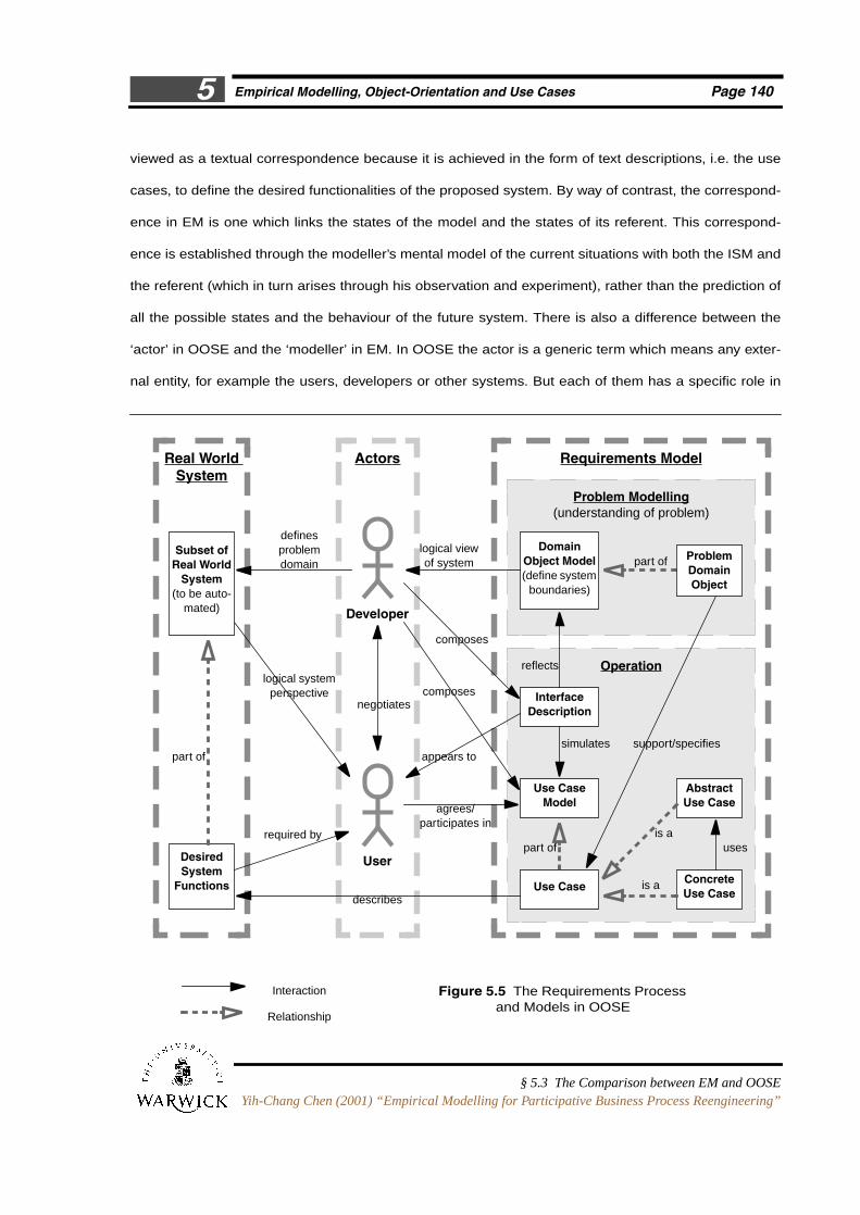
Figure 5.5 depicts the Requirements Process of OOSE and the relationships among the models
created during this process. This can be compared with Figure 5.6 (reproduced from Figure 4.2 in chap-
ter 4) to show the differences between OOSE and EM in requirements-oriented activity. The main differ-
ence between these two approaches is in the correspondences between the real world system and the
models. In OOSE, such correspondence is established through the developer’s pre-understanding of
the problem domain as well as the negotiations with the customers and the future users. This can be
Director and analyst identifysubset of behaviours as suita-ble for computer automation
OOSE (Use Case Driven)
Figure 5.4 Contrast between OOSE and EM Approaches to System Development
EM Approach
LSD descriptionof whole domain
= the ‘system’
(e.g. storage of information+ communication of orders)
ADM machinemodel with modeller(validation)
(all behaviour ofdomain latent)
incrementally iden-tify behaviours toautomate
Problem Domain ModelInterface DescriptionUse-Case Model
Analysis Model
Testing (Validation)
Construction
= Analysis
= Requirement Model
Useful Computer System
+
Office
ACME Storage Company
W1
W2 W3
Empirical Modelling, Object-Orientation and Use Cases Page 1405
§ 5.3 The Comparison between EM and OOSEYih-Chang Chen (2001) “Empirical Modelling for Participative Business Process Reengineering”
viewed as a textual correspondence because it is achieved in the form of text descriptions, i.e. the use
cases, to define the desired functionalities of the proposed system. By way of contrast, the correspond-
ence in EM is one which links the states of the model and the states of its referent. This correspond-
ence is established through the modeller’s mental model of the current situations with both the ISM and
the referent (which in turn arises through his observation and experiment), rather than the prediction of
all the possible states and the behaviour of the future system. There is also a difference between the
‘actor’ in OOSE and the ‘modeller’ in EM. In OOSE the actor is a generic term which means any exter-
nal entity, for example the users, developers or other systems. But each of them has a specific role in
Figure 5.5 The Requirements Processand Models in OOSE
Real WorldSystem
Requirements Model
Problem Modelling(understanding of problem)
Developer
definesproblemdomain
logical systemperspective
logical viewof system
appears to
composes
describesUse Case
Subset ofReal World
System(to be auto-
mated)
DesiredSystem
Functions
User
Actors
ConcreteUse Case
AbstractUse Case
Use CaseModel
InterfaceDescription
Operation
DomainObject Model(define system
boundaries)
part of
reflects
simulates
part of usesis a
is a
support/specifiespart of
required by
agrees/participates in
negotiatescomposes
Interaction
Relationship
ProblemDomainObject

Empirical Modelling, Object-Orientation and Use Cases Page 1415
§ 5.3 The Comparison between EM and OOSEYih-Chang Chen (2001) “Empirical Modelling for Participative Business Process Reengineering”
interacting with the system. For EM the modeller can be a designer or user or any other participant.
There is no specific role for the modeller as he can interact with the ISM in a flexible and open-ended
manner. Through this, different types of interactions with the real world can be simulated by interacting
with the ISM. The right-hand block in Figure 5.5 representing the Requirements Model of OOSE can
only reflect the inner block of the executable area in Figure 5.6. This means the domain of OOSE is
mainly the ‘system’ itself, whereas the domain of EM involves the real world situation which could be
outside our prediction of the system states. It is also interesting to see that in OOSE the activity of
understanding of the problem domain (the upper inner block) and the activity of requirements/function-
Figure 5.6 Empirical Modelling and its Tools and Notations (copy of Figure 4.2)
Real WorldDomain
Domain Model(Conceptual Model)
RealWorld
Referent
Executable Area(Current-State Model)
LSD
ADM / EDEN
ISM
Dependency
(elicitation of‘variables’)
(validationagainst)
The Modellers
Dependency
display device
Script of Definitions +Stimuli-Response Patterns
agents observationsdefinitions protocols
observations
experiment
revision &experiment
observations
describing
correspondences(inter-relations
between the modeland the real world)
(used for)
(used for)
(redefine)
(redefine)
define
derivate protocol
definition action
DoNaLDScoutEDEN
(redefini-tion)
translate
instantiate
definition action
implement
LSD
ADM
tkeden
(EM Notations)
DoNaLDScoutEDEN
(definition)
variables
Variables(model components)state oracle handlederivate protocol
Observ-ables
(real worldexample frag-
ments)
Observ-ables Interactive
Interface
visualisation
Entity
Agent
DefinitiveNotation

Empirical Modelling, Object-Orientation and Use Cases Page 1425
§ 5.3 The Comparison between EM and OOSEYih-Chang Chen (2001) “Empirical Modelling for Participative Business Process Reengineering”
ality description (the lower inner block) are separate whereas in EM these two activities are ‘fused’.
(These issues will be further discussed in the next subsection.)
Finally, it remains to discuss the user interface. In OOSE, the user interface description is created
before the actual system is developed. It serves as a prototype and many use cases here will often
need the description of such an interface. This kind of prototype differs from the ‘prototype’ of the EM
model. In OOSE the interface is static and passive, and the actor’s interactions with the interface are
represented by single arrows. The interface of the EM model represents a ‘virtual prototype’ but one
which is integrated as part of the whole model and is as open to interactive modification as any other
part of the model.
Understanding of the Domain
The activities of understanding of the domain in the requirements analysis are done by the Domain
Object Model in OOSE and the LSD account in EM. The Domain Object Model mainly serves as a logi-
cal view of the proposed system. It consists of problem domain objects which represents the entities
from the problem domain which the system must know. Through this model some concepts which the
system should work with can be defined. In EM the LSD account records the modeller’s conception of
the situation. This account captures the observables and dependencies which are significant or rele-
vant, the agents which are present and the classification of observables based on the view of these
agents. We can compare the Domain Object Model and LSD in the following ways:
Objective vs Subjective The Domain Object Model, as well as other conventional models, is
objective because it is constructed to acquire the objective knowledge about the system behaviour in
order to achieve a specified goal. As Jacobson et al. point out, the Domain Object Model is to enable
the users to recognise all the concepts needed when defining the functionalities of the system. It is also
the tool for users and designers to communicate about the system. This model is developed through
discussion among these people and aims to form an objective base for understanding of the domain
and the development of the Use Case Model. In contrast, the LSD account is subjective as it represents
Empirical Modelling, Object-Orientation and Use Cases Page 1435
§ 5.3 The Comparison between EM and OOSEYih-Chang Chen (2001) “Empirical Modelling for Participative Business Process Reengineering”
only the modeller’s perception and experience of a particular subject in a particular situation. It is sub-
jective because in EM, the definitive script or the activity of constructing an ISM is tentative and provi-
sional and is open to change and extension in order to meet changing requirements as well as the
changing environment. In this sense, Beynon et al. (2001) characterise the computer as an instrument
(or interactive instrument) whereas in conventional approaches the computer is a tool. In other words,
the instrument-like use of artefacts is more subjective because the emphasis of using instruments is on
exercising personal skills; and the tool-like use of artefacts is more objective because the use of tools is
to perform a specific function or goal in a organised and public pattern of interactions. Within the EM
context, the LSD account records the modeller’s conception of the referent which may be different to the
objective knowledge of the referent or the intended functionality and interaction with that referent. This
characteristic differs from those methodologies which seek to form a formal specification. Ness (1997)
classifies the conventional (object-oriented) methodologies as being like an agentless or 0-agent sys-
tem in EM because of their absence of considering the role of the modeller in the process.
Domain The problem domain of OOSE is mainly the ‘system’ itself, i.e. the aim of the OOSE
development process is to build a new system to replace the existing one. Thus the domain defined in
OOSE is a part of the real world in which the activities or processes can be replaced or automated by
the new system. For this situation it is essential to define the boundary of the system at an early stage
in order to develop a system which is meaningful and useful for its users. In comparison, the domain of
EM involves the real-world situation. That is, the domain of EM involves the situations which reflect to
some extent the way in which the modeller perceives, and interacts with, the world. Even the past expe-
rience of the modeller or the legacy of other people’s experience can be drawn on here. The states in
the EM model are a metaphorical representation of the relevant situations in the real world. The possi-
ble transitions between states are recorded within the LSD account in terms of agents, observables and
dependencies. This LSD account is consistent with the modeller’s construal of the referent.
System Behaviour The system behaviours in OOSE models are preconceived because these
behaviours have to be defined at an early stage in order to construct the subsequent models. In the Use
Case Model, each functionality, or usage, of the proposed systems is defined by a use case and its

Empirical Modelling, Object-Orientation and Use Cases Page 1445
§ 5.3 The Comparison between EM and OOSEYih-Chang Chen (2001) “Empirical Modelling for Participative Business Process Reengineering”
potential users are defined by actors. Normally such functionalities or usages defined in use cases are
based on the frameworks which have been identified earlier to be reliable or predictable. This model
serves as an agreement between the customers and the designers in which the clear description of the
system functionalities is included. Thus we can say the focus of OOSE methods is on the representa-
tion of the system behaviour. In contrast, the system modelled by EM exhibits the same behaviours
which may be appropriate to the applications but, in the process of development, they are not precon-
ceived. Such behaviour is represented in the EM model as immediately experienced rather than circum-
scribed. This is because the changes in the states of the EM model are not anticipated and thus cannot
be derived in advance. However, it is still possible to circumscribe the system behaviour within the EM
model just as in other models, and the modeller can introduce agents or dependencies in the order
which is appropriate.
Ontology vs Epistemology An important issue, relevant to the discussion above, is whether
the philosophical orientation of a system development approach is towards ontology or epistemology.
The philosophy of object-orientation is generally viewed as concerned with ontology15 – the common
way of thinking of ‘object’ is as a representation of a real-world entity, i.e. any real-world entity is an
object (cf. section 2.2). Thus the OO models are objective in character and their artefact use is tool-like,
and their domain is limited to the proposed system itself. In contrast, the philosophy of EM modelling is
more related to epistemology because we are emphasising experiment and long-established practice
during the process of modelling. This is similar to the outlook of Checkland’s SSM and Lehman’s E-type
program that were described in chapter 2. Lewis (1995) comments that the philosophical orientation
may not be significant when OO is applied at the implementation level for a problem domain which is
well-defined. But if applied in less well-defined situations, then “the assumption of one-to-one corre-
spondences existing between the objects in the data model and parts of the external [real-world] reality
is more dangerous and blinkering”16. And McGinnes (1992) has the same view:
15.Lewis (1993 and 1995) has a different viewpoint. He mentions that “the recent interest in object-oriented analysishas led to re-interpretations of the nature of data analysis and at least some recognition that a data model mightbe an epistemological device, a coherent means of investigating the problem domain rather than being a descrip-tion of the real world” (Lewis, 1993). We will further continue this discussion later in this paragraph.

Empirical Modelling, Object-Orientation and Use Cases Page 1455
§ 5.3 The Comparison between EM and OOSEYih-Chang Chen (2001) “Empirical Modelling for Participative Business Process Reengineering”
The idea that object-oriented systems are a ‘natural’ representation of the world is a
seductive but dangerous over-simplification. In reality, the fact that the object model
seems so close to reality makes it far easier to misuse than other modelling techniques
which do not propose to represent the world so directly. (p. 13)
Many researchers (Winograd and Flores, 1987; Stowell, 1995b; Mingers, 1995; Lewis, 1995; Checkland
and Scholes, 1990) argue that OO and many traditional methodologies which are based on an objectiv-
ist viewpoint are inappropriate for designing information systems as they are a part of the whole proc-
ess of human communication. Instead they argue that human interaction involves understanding and
meaning17, and thus our actions cannot simply be described objectively by an external observer. Thus
Mingers (1995) describes the task of system analysts as not simply the objective description of particu-
lar information flows or data structures, but as the interpretation and elicitation of the socially con-
structed patterns of meaning which generate observed behaviour. For EM we do not aim to model the
proposed system directly through one-to-one mapping in a preconceived manner, but rather focus on
the process of human agent’s perception and experiment with the real-world reality. This is consistent
with the view of Lewis (1995), who suggests that OO analysis, as well as other models or database, is
not modelling the real-world reality, but modelling the way the reality is understood by people – they are
the models of user’s models of the world18. Thus the analysis leads to models which do not reflect any
objective reality but a particular group’s knowledge and perceptions of a problem situation. Thus we
need ways to investigate and model that knowledge and perception, especially ways “that are sympa-
thetic to the complex manner in which social realities are created”. The EM approach can in this sense
complement other analysis approaches, because, as Lewis says, with current methods, analysis “con-
16.He gives an example of whether a ‘country’ is a tangible item (an object) in the real world or a perception sharedby many individuals: “Did there exist a real-world thing called Slovenia in December 1991 when some inhabitantsof Yugoslavia had declared its independent existence? Did it exist in January 1992 when the European Commu-nity (but not the United Nations or the governments of Yugoslavia) recognised its existence? The answers, ofcourse, depend on how we define ‘a country’, and this is socially and politically decided: it is not an absolute char-acteristic of something existing in an independent ‘real-world’ ”. (pp. 194-195)
17.This is why Checkland and Scholes (1990) say “information equals data plus meaning”, and Galliers (1995) con-trasts information systems (which inform) from data-processing systems (which automate the operational tasks).Goguen (1994 and 1996) comments that information is situated – it is highly dependent on its social context forinterpretation and we have to consider how it is produced rather than merely how it is represented.
18.Thus the question for evaluating models should not be “Does this design accurately represent the real world?”,but should be “Does this design accurately represent the user’s model of his environment?”.

Empirical Modelling, Object-Orientation and Use Cases Page 1465
§ 5.3 The Comparison between EM and OOSEYih-Chang Chen (2001) “Empirical Modelling for Participative Business Process Reengineering”
tains no model of human sense-making that explains it, and none of the techniques of data modelling
assists by making the subjectivity explicit and open to debate”.
Functional Requirements Description
In OOSE the functionalities of the proposed system are defined in the Requirements Model. The first
step in the requirements process is to create a simple prototype of the system which helps to describe
the boundary and the actors of the system. Then the functional behaviours of that system are described
by the informal text descriptions in use cases. Jacobson et al. (1992) calls the content of the use cases
interface descriptions (or use case specifications) because they define the interface between the users
and the system itself. The use case specification consists of both textual and graphic descriptions. It
also consists of various phases each representing a particular set of behaviours in that use case.
In EM the ADM or EDEN is used to animate the LSD account. Through the animation the interac-
tion between agents in LSD will be visible and meaningful and the modeller can intervene in the model
by adding or redefining definitions. Through this kind of interaction the modeller can ensure whether the
system behaviour meets the requirements with reference to the external observation. The following is a
comparison of the techniques of functional requirements description between OOSE and EM.
Verbal (Text-Based) vs Machine-Support Use cases are written in natural language to
describe the dynamic process of using the system. According to Jacobson et al., use cases are easy to
understand and provide a better way for communicating with customers and users. However Dano et al.
(1996) point out that although the description of the use cases makes the involvement of domain
experts easier, it is still not entirely satisfactory because the designers have to make sure no require-
ment is misunderstood as well as ensure the completeness and consistency. Further, such a kind of
communication is still passive and Sun et al. (1999) argue that the shared understanding of all partici-
pants within this kind of text-based model is invisible and incommunicable. Inevitably the visibility and
communicability of shared understanding is restricted to the boundaries of language description or
comprehension. Also it is hard to keep the requirements specifications synchronous with changing
Empirical Modelling, Object-Orientation and Use Cases Page 1475
§ 5.3 The Comparison between EM and OOSEYih-Chang Chen (2001) “Empirical Modelling for Participative Business Process Reengineering”
requirements as the people involved gain a better understanding of the problem and may change their
points of view or focus. Maintenance may also be a problem because a change in the requirements may
affect many places in the text of the specification. In other words, there can be many versions of a use
case. This is especially problematic while developing a complex system as too many or too complex
scenarios cannot be fully described by text-based models. But if we can animate these versions and
then test them, we will get a kind of feedback through the visual artefact during the analysis and design.
And once we have the feedback, we will be able to improve the requirements specification and generate
a new version of a use case easily. This is what we have been doing in our EM research. In EM the
interaction with the ISMs can make the modeller’s insights and the shared understanding with other par-
ticipants visible and communicable. Pictures are more informative than the textual descriptions: “A
graphic is worth a thousand words”. In EM the computer is used to generate the metaphorical represen-
tation of particular states and to animate the modeller’s expectations about the results after state-
changing actions. Interaction with the computer model will lead to the evolution of the modeller’s
insights as well as a shared understanding. Conventionally, much knowledge (especially tacit knowl-
edge) is kept in the participants but cannot reach the corporate knowledge. But in the EM modelling
process, we are trying to make such tacit knowledge and other trial-and-error knowledge accessible to
the decision process. The knowledge through the interaction with ISMs can solve the text-based prob-
lem in the use cases and other methodologies. For this reason, EM can be regarded as an alternative
approach for creating use case specifications. The difference between the different versions of use
cases is mainly from the change of responsibilities of objects or the addition of new objects. EM allows
such kinds of change to be made ‘on-the-fly’ by redefining or adding definitions in the script. Sun et al.
describe this synchronisation between the evolution of computer models and modeller’s insights allow-
ing the participants to ‘see’ the viewpoints of others and to ‘communicate’ with them by interacting with
versions of their artefact. Another advantage of the EM models is, it can capture the richer reality of the
real-world situation and make the revision of the model easier and more faithful to reality.
Scenarios In OOSE, a use case in its normal course and alternative courses can be regarded as
a collection of the possible scenarios between the actors and the system. That is, a use case describes

Empirical Modelling, Object-Orientation and Use Cases Page 1485
§ 5.3 The Comparison between EM and OOSEYih-Chang Chen (2001) “Empirical Modelling for Participative Business Process Reengineering”
the possible scenarios of user’s interaction with the system and represents the steps to accomplish the
result.
Figure 5.7 illustrates some different types of scenarios in system development. The first type of sce-
nario is the system internal scenario which consists of the interactions of the internal components within
the proposed system. This kind of scenario is described by the use case specifications and is modelled
by the following Analysis Model, in which the external context of the system is not considered. The sec-
ond type of scenario is the interactions between the system and a part of its external environment,
which only includes the actors and other systems directly interacting with the proposed system. Such
scenarios are defined in the Use Case Model. The third type of scenario includes the wider context of
the external environment. In addition to the direct interactions between the system and its context, it
also includes the information about the context of that system. We argue that the scenarios in the EM
model are categorised into this type because the state of the referent is metaphorically represented in
the EM model and the consequent results of the state-changing actions by the modeller may or may not
meet his expectation. Obviously the EM technique can be applied to model all these types of scenarios.
For example, the perspective of an external observer, as described in ‘Scenario 1’19 in Beynon (1997),
Figure 5.7 The Scenarios in System Development
Actor
OtherSystems
The System
Use Case
Use Case
Use Case
Actor
OtherStakeholder
OtherResources
(2nd Type of Scenario)(3rd Type of Scenario)
(1st Type of Scenario)

Empirical Modelling, Object-Orientation and Use Cases Page 1495
§ 5.3 The Comparison between EM and OOSEYih-Chang Chen (2001) “Empirical Modelling for Participative Business Process Reengineering”
is similar to – but even broader than – that of the designer in OOSE, as the functionality of the proposed
system and possible interaction of users have to be identified in the Use Case Model before the objects
and their interactions are modelled. The first type of scenario can be represented through the interac-
tion of internal agents in the EM model. However, according to systems thinking, each agent (or object)
can be specified, but the whole system behaviour made up of the cooperation of their interactions may
sometimes lead to conflict or incoherence. This explains why sometimes existing methods fail to
develop a system to meet the user’s actual needs as they did not take the third (or even the second)
type of scenario into consideration when developing the system.
Systems-Oriented vs Agent-Oriented The use case is systems-oriented because it
defines and captures the major functionality of the proposed system. It is user-centred because the aim
of use cases is to ensure the system is developed to meet the requirements from the user’s viewpoint. A
use case may involve many actors, but only one actor initiates the use case. However the actors are
beyond the scope of the system considered, the use case modelling does not consider the interactions
between actors. In contrast, EM is agent-oriented because its process involves the identification of
agents as well as the observables and dependencies in the subject. However the concept of agent-ori-
entation is different to the one in the AI field. In EM the agents are state-changing agents which refer to
entities related to the representation and transformation of the state, for example the individual compo-
nents of the system or the potential users and designers of the system. The agents in EM can directly
change the value of a variable owned by other agents. Changes to the state are caused by agents and
constrained by the capabilities (i.e. the privileges for change) of the agents. Thus the agents identified
reflect the perspective of the observer. The system behaviour is implicitly defined by the privileges of
agents. The introduction of new agents or new privileges of existing agents will affect the system behav-
iour. This is different to OOSE as the system behaviour comes from the circumscribed way of observa-
tion and description, and the objects and their interactions are identified afterwards.
19.Scenario 1: the modelling activity is centred around an external observer who can examine the system behaviour,but has to identify the component agents and infer or construct profiles for their interaction; Scenario 2: the sys-tem can be observed from the perspectives of its component agents, but an objective viewpoint or mode of obser-vation to account for the corporate effect in their interaction is to be identified (Beynon, 1997).

Empirical Modelling, Object-Orientation and Use Cases Page 1505
§ 5.3 The Comparison between EM and OOSEYih-Chang Chen (2001) “Empirical Modelling for Participative Business Process Reengineering”
Programming through Modelling vs Modelling through Programming
Beynon and Joy (1994) describe the primary motivation of the EM paradigm as a philosophy of pro-
gramming as modelling or perhaps more clearly programming through modelling. That is, using model-
ling as a means to program a computer. This idea differs from the concerns of object-orientation and
other modelling methodologies which can be characterised as modelling through programming as we
program the computer in order to model a system.
By ‘programming through modelling’, the emphasis of EM is to model what we observe of the whole
system and its environment in terms of interacting agents, rather than constructing the models inde-
pendently of the real world situation. One advantage of the EM approach is that we can specify the syn-
chronised changes which may cut across the object boundaries. Further, according to Beynon and Joy,
the development process of the EM models is the process of formulating relationships (i.e. the depend-
encies) between observables which are provisional. This means that the EM models can be viewed as
a specification of a program only after the majority of the modelling process has been done, i.e. the reli-
ability of the relevant observations have been validated. By way of contrast, in OO methods the specifi-
cation of the system is decided before the construction of models. For EM, the emphasis is on software
construction to establish a prototype of the real-world system within the computer; whereas in OO the
emphasis is on developing a finished model based on the requirements which are in turn based on the
assumptions and initial experience of the real-world system (Rawles, 1997).
5.3.2 Comparison between the Models
This subsection will compare the similarities and differences between the EM model and the models of
object-orientation (and OOSE). For EM we are concerned with matters of state in ISMs and comparing
this with the states of OO models in terms of the different characteristics of agents and objects. We also
consider the issues of modularity and reusability, which are fundamental features of OO, to find out the
different concept used in the EM model.

Empirical Modelling, Object-Orientation and Use Cases Page 1515
§ 5.3 The Comparison between EM and OOSEYih-Chang Chen (2001) “Empirical Modelling for Participative Business Process Reengineering”
The Concept of State
EM differs from conventional programming in that the focus of EM modelling is on state rather than the
structure of control or the representation of behaviour. The ‘state’ here broadly includes the state of
mind in the subjective experience of the modeller as well as the states of the artefact and its referent.
The values of variables in the EM model at a time correspond to a particular state in the real world. The
change of state is only achieved through the automatic update of dependencies or the explicit action of
agents, that is, through redefinitions or the addition of new definitions. Thus change can be made at any
time during the animation. For EM the concept of state, which differs from the public sense, is primarily
state-as-perceived-by-agent or state-as-experienced. That is, the state represents what the person cur-
rently perceives/experiences of the environment and is subject to continuous change. In most conven-
tional approaches, such a subjective state is not directly represented. In order to prescribe the process,
the inputs and outputs have to be preconceived before the construction of the model. The OOSE
method is an example of emphasis on prescribing the system behaviour in use cases before construct-
ing the model. If any new inputs and outputs and additional features of systems need to be added, the
revision and redesign of the whole process may cost time and effort. Also the EM model seems to be
more robust than the OO model: because EM enables the user to experience an unfamiliar situation,
which includes unexpected situations or even abnormal conditions.
Generally in object-oriented programming, the representation of states is through the identification
of the state of each object. Thus we can identify the difference between agents of EM and objects in OO
in modelling state-transitions. In object-orientation, each object is responsible for changing its state
through performing its internal action or method. Other objects can send a message to an object to
invoke its method. The message passing is the only way in which these objects interact and thus
change their internal variables and states. This is different from the agents of EM in which the actions of
one agent can directly affect the changes of state in other agents, and sometimes result in an indivisible
propagation of state changes which involve several agents. The agents in EM can be either active or
passive. The active agents can perform autonomous actions to change the state of the model; whereas
the passive agents serve to record state information but cannot perform actions (Beynon et al., 1990).

Empirical Modelling, Object-Orientation and Use Cases Page 1525
§ 5.3 The Comparison between EM and OOSEYih-Chang Chen (2001) “Empirical Modelling for Participative Business Process Reengineering”
The character of passive agents may be close to that of objects in OO. The system state represented in
OO models is more tricky than in an EM model, because the designers need additional information
about the message sending, receiving and responding for objects in order to understand the system
behaviour.
When BPR is concerned, the mathematical models used in conventional methods are not suitable
for modelling states in the business environment. It is essential to identify the factors which affect the
manager’s or user’s perception of the state of the business which they are in. Such factors cannot be
appropriately represented in the mathematical model. As Beynon et al. (2000a) describe, modelling
these factors involves consultation with other related parties, the development of physical artefacts or
prototype products, and computational models based around databases and spreadsheets. In the next
chapter we will illustrate an ISM which encompasses models of this nature and is well-suited to model-
ling business processes.
Issues of Modularity and Reusability
Modularity is one of the fundamental properties of the object-oriented methodology which has made
OO popular and makes system development more effective. The central theme of object-orientation is
to synthesise the software system from modules which can be developed independently. But the
decomposition into objects in the OO paradigm means a commitment and knowledge about the prob-
lem domain is needed before defining the behaviour and attributes of objects. From the viewpoint of the
object-oriented paradigm, it is essential to minimise the dependencies between modules for the reason
of maintenance and reusability. In the construction of large systems, the division into modules some-
times can be a difficult task.
In EM the emphasis is on observation rather than the object. That is, our emphasis is on modelling
the observation of the whole system with interacting agents but not constructing objects in isolation and
then integrating them by means of message passing. The observables and variables in the EM model
are global. The indivisible propagation of state changes in the EM model will result in state changes

Empirical Modelling, Object-Orientation and Use Cases Page 1535
§ 5.3 The Comparison between EM and OOSEYih-Chang Chen (2001) “Empirical Modelling for Participative Business Process Reengineering”
across the object boundaries. This makes EM more suitable than object-orientation in the synchronisa-
tion design of system development, due to the synchronised updates of variables through definitions. In
OO the protocols between objects are not made explicit and thus the synchronisation of messages can-
not be specified.
On the other hand, as there is no kind of modularity in the EM model, the issue of reuse cannot be
coped with well within EM. For object-orientation, each object can be easily reused due to the features
of encapsulation and information hiding. Some techniques, for example isolating the agents and
observables, can make some kind of modularity in the definitive scripts, it is still hard to achieve modu-
larity in the EM model because of the rich dependencies in the definitive scripts. Rawles (1997) sug-
gests two structures for applying the idea of modularity in the EM paradigm. The first is through the
construction of scripts, each of which models an individual element of the system. But this does not
make it different to normal EM modelling because the system is still developed as a whole. This only
makes the modeller construct the scripts more conveniently and easily, i.e. splitting the scripts into
some conceptual chunks. In this case the scripts may be reusable. But the modeller will still make more
effort to reuse such scripts than to reuse objects in OO in which only the change of class interface is
needed. The second is using agents as modular units. However even if we modularise the agents, they
are still with global character due to their observables and the dependencies between them. Further
work such as localising these dependencies may be needed. This indicates the need for further investi-
gation into the status of modular design within the EM framework.
Even though software reusability has been regarded as a claim for object-orientation, Gammack
(1995) points out that such software reusability still has been a massive problem for the industry.
Together with other researchers, he concludes that
hardware reuse benefits from the fact that standard functions are easy to identify owing
to their close mapping into the real-world model of hardware systems, and if software
reusability is to become a reality languages must support a more direct mapping from
the model of the real world functions to the implementation. (p. 165)

Empirical Modelling, Object-Orientation and Use Cases Page 1545
§ 5.4 Concluding RemarksYih-Chang Chen (2001) “Empirical Modelling for Participative Business Process Reengineering”
This argument is closely related to the discussion of relationships between software (or the software
system) and the real world (its business environment) in section 3.3. Such discussion may provide
another direction for research into software reusability within the EM framework.
5.4 Concluding Remarks
The concept of use cases has become more and more popular in the object-oriented community and
has been established as one of the fundamental techniques of the OO methodology. It provides some
advantages in the process of requirements elicitation which the conventional object-oriented methods
failed to achieve. But like many other development methods, there are still some problems when apply-
ing the use case technique in developing the system. This chapter summarises the general concepts of
the use case technique and the processes of applying this technique in both system development
(OOSE) and BPR (Object Advantage). We also gave an overview of the drawbacks associated with use
cases.
The concepts of the EM approach have been described in chapter 4. Several EM projects have
identified issues of common interest in the EM approach and object-oriented approaches (including the
use case approach). Related work on this theme can be found in Ness (1997), Rawles (1997), Beynon
and Joy (1994) and other research reports of the EM and AMORE projects. In this chapter we have
compared these two approaches mainly in regard to software development. The comparison is based
on two concerns: first, their processes of system development which involve the construction of the
models; and second, the structures and characteristics of their models.
The paradigm of object-orientation has been long established and been widely accepted for soft-
ware development. But EM is a novel approach to modelling which has been developed for just over 15
years. The research of EM projects shows that EM can bring a new approach to development in some
different fields, for example, business modelling. Through this comparison, it is hoped that we gain a
better understanding of how the EM approach can relate to existing methodologies of system develop-
ment as well as an appreciation of how this approach can itself be used in system development.